EP4037088A2 - Electrode terminal and use thereof - Google Patents
Electrode terminal and use thereof Download PDFInfo
- Publication number
- EP4037088A2 EP4037088A2 EP22152967.0A EP22152967A EP4037088A2 EP 4037088 A2 EP4037088 A2 EP 4037088A2 EP 22152967 A EP22152967 A EP 22152967A EP 4037088 A2 EP4037088 A2 EP 4037088A2
- Authority
- EP
- European Patent Office
- Prior art keywords
- electrode terminal
- negative electrode
- insertion hole
- secondary battery
- welded
- Prior art date
- Legal status (The legal status is an assumption and is not a legal conclusion. Google has not performed a legal analysis and makes no representation as to the accuracy of the status listed.)
- Pending
Links
- 238000003780 insertion Methods 0.000 claims abstract description 33
- 230000037431 insertion Effects 0.000 claims abstract description 33
- 229910052751 metal Inorganic materials 0.000 claims abstract description 20
- 239000002184 metal Substances 0.000 claims abstract description 20
- 150000002739 metals Chemical class 0.000 claims description 5
- 238000005516 engineering process Methods 0.000 abstract description 8
- 238000003466 welding Methods 0.000 description 43
- 239000000523 sample Substances 0.000 description 19
- 229910052782 aluminium Inorganic materials 0.000 description 10
- XAGFODPZIPBFFR-UHFFFAOYSA-N aluminium Chemical compound [Al] XAGFODPZIPBFFR-UHFFFAOYSA-N 0.000 description 10
- 239000000463 material Substances 0.000 description 8
- RYGMFSIKBFXOCR-UHFFFAOYSA-N Copper Chemical compound [Cu] RYGMFSIKBFXOCR-UHFFFAOYSA-N 0.000 description 7
- HBBGRARXTFLTSG-UHFFFAOYSA-N Lithium ion Chemical compound [Li+] HBBGRARXTFLTSG-UHFFFAOYSA-N 0.000 description 6
- 229910052802 copper Inorganic materials 0.000 description 6
- 239000010949 copper Substances 0.000 description 6
- 229910001416 lithium ion Inorganic materials 0.000 description 6
- 230000015572 biosynthetic process Effects 0.000 description 5
- 239000007773 negative electrode material Substances 0.000 description 5
- 239000007774 positive electrode material Substances 0.000 description 5
- PXHVJJICTQNCMI-UHFFFAOYSA-N Nickel Chemical compound [Ni] PXHVJJICTQNCMI-UHFFFAOYSA-N 0.000 description 4
- 229910045601 alloy Inorganic materials 0.000 description 4
- 239000000956 alloy Substances 0.000 description 4
- 239000011347 resin Substances 0.000 description 4
- 229920005989 resin Polymers 0.000 description 4
- 230000000694 effects Effects 0.000 description 3
- 238000009413 insulation Methods 0.000 description 3
- 238000005304 joining Methods 0.000 description 3
- 238000004519 manufacturing process Methods 0.000 description 3
- 239000004813 Perfluoroalkoxy alkane Substances 0.000 description 2
- 239000004734 Polyphenylene sulfide Substances 0.000 description 2
- 239000011230 binding agent Substances 0.000 description 2
- 239000003990 capacitor Substances 0.000 description 2
- 238000007599 discharging Methods 0.000 description 2
- 230000002349 favourable effect Effects 0.000 description 2
- 239000012212 insulator Substances 0.000 description 2
- 229910052759 nickel Inorganic materials 0.000 description 2
- 239000011255 nonaqueous electrolyte Substances 0.000 description 2
- 229920011301 perfluoro alkoxyl alkane Polymers 0.000 description 2
- 229920000069 polyphenylene sulfide Polymers 0.000 description 2
- 125000006850 spacer group Chemical group 0.000 description 2
- 238000003860 storage Methods 0.000 description 2
- 238000012546 transfer Methods 0.000 description 2
- YCKRFDGAMUMZLT-UHFFFAOYSA-N Fluorine atom Chemical compound [F] YCKRFDGAMUMZLT-UHFFFAOYSA-N 0.000 description 1
- UFHFLCQGNIYNRP-UHFFFAOYSA-N Hydrogen Chemical compound [H][H] UFHFLCQGNIYNRP-UHFFFAOYSA-N 0.000 description 1
- FKNQFGJONOIPTF-UHFFFAOYSA-N Sodium cation Chemical compound [Na+] FKNQFGJONOIPTF-UHFFFAOYSA-N 0.000 description 1
- 239000002800 charge carrier Substances 0.000 description 1
- 239000004020 conductor Substances 0.000 description 1
- 239000000470 constituent Substances 0.000 description 1
- 239000011889 copper foil Substances 0.000 description 1
- 238000013461 design Methods 0.000 description 1
- 239000003792 electrolyte Substances 0.000 description 1
- 229910052731 fluorine Inorganic materials 0.000 description 1
- 239000011737 fluorine Substances 0.000 description 1
- 239000011888 foil Substances 0.000 description 1
- 230000020169 heat generation Effects 0.000 description 1
- 238000010438 heat treatment Methods 0.000 description 1
- 229910052739 hydrogen Inorganic materials 0.000 description 1
- 239000001257 hydrogen Substances 0.000 description 1
- 239000007769 metal material Substances 0.000 description 1
- 238000012986 modification Methods 0.000 description 1
- 230000004048 modification Effects 0.000 description 1
- 238000012545 processing Methods 0.000 description 1
- 238000007789 sealing Methods 0.000 description 1
- 229910001415 sodium ion Inorganic materials 0.000 description 1
- 239000010935 stainless steel Substances 0.000 description 1
- 229910001220 stainless steel Inorganic materials 0.000 description 1
- 239000000126 substance Substances 0.000 description 1
Images


Classifications
-
- H—ELECTRICITY
- H01—ELECTRIC ELEMENTS
- H01M—PROCESSES OR MEANS, e.g. BATTERIES, FOR THE DIRECT CONVERSION OF CHEMICAL ENERGY INTO ELECTRICAL ENERGY
- H01M50/00—Constructional details or processes of manufacture of the non-active parts of electrochemical cells other than fuel cells, e.g. hybrid cells
- H01M50/50—Current conducting connections for cells or batteries
- H01M50/543—Terminals
- H01M50/564—Terminals characterised by their manufacturing process
- H01M50/566—Terminals characterised by their manufacturing process by welding, soldering or brazing
-
- H—ELECTRICITY
- H01—ELECTRIC ELEMENTS
- H01M—PROCESSES OR MEANS, e.g. BATTERIES, FOR THE DIRECT CONVERSION OF CHEMICAL ENERGY INTO ELECTRICAL ENERGY
- H01M50/00—Constructional details or processes of manufacture of the non-active parts of electrochemical cells other than fuel cells, e.g. hybrid cells
- H01M50/50—Current conducting connections for cells or batteries
- H01M50/543—Terminals
- H01M50/552—Terminals characterised by their shape
- H01M50/553—Terminals adapted for prismatic, pouch or rectangular cells
- H01M50/557—Plate-shaped terminals
-
- H—ELECTRICITY
- H01—ELECTRIC ELEMENTS
- H01M—PROCESSES OR MEANS, e.g. BATTERIES, FOR THE DIRECT CONVERSION OF CHEMICAL ENERGY INTO ELECTRICAL ENERGY
- H01M50/00—Constructional details or processes of manufacture of the non-active parts of electrochemical cells other than fuel cells, e.g. hybrid cells
- H01M50/50—Current conducting connections for cells or batteries
- H01M50/543—Terminals
-
- H—ELECTRICITY
- H01—ELECTRIC ELEMENTS
- H01M—PROCESSES OR MEANS, e.g. BATTERIES, FOR THE DIRECT CONVERSION OF CHEMICAL ENERGY INTO ELECTRICAL ENERGY
- H01M50/00—Constructional details or processes of manufacture of the non-active parts of electrochemical cells other than fuel cells, e.g. hybrid cells
- H01M50/10—Primary casings; Jackets or wrappings
- H01M50/172—Arrangements of electric connectors penetrating the casing
-
- H—ELECTRICITY
- H01—ELECTRIC ELEMENTS
- H01M—PROCESSES OR MEANS, e.g. BATTERIES, FOR THE DIRECT CONVERSION OF CHEMICAL ENERGY INTO ELECTRICAL ENERGY
- H01M50/00—Constructional details or processes of manufacture of the non-active parts of electrochemical cells other than fuel cells, e.g. hybrid cells
- H01M50/20—Mountings; Secondary casings or frames; Racks, modules or packs; Suspension devices; Shock absorbers; Transport or carrying devices; Holders
- H01M50/204—Racks, modules or packs for multiple batteries or multiple cells
- H01M50/207—Racks, modules or packs for multiple batteries or multiple cells characterised by their shape
- H01M50/209—Racks, modules or packs for multiple batteries or multiple cells characterised by their shape adapted for prismatic or rectangular cells
-
- H—ELECTRICITY
- H01—ELECTRIC ELEMENTS
- H01M—PROCESSES OR MEANS, e.g. BATTERIES, FOR THE DIRECT CONVERSION OF CHEMICAL ENERGY INTO ELECTRICAL ENERGY
- H01M50/00—Constructional details or processes of manufacture of the non-active parts of electrochemical cells other than fuel cells, e.g. hybrid cells
- H01M50/50—Current conducting connections for cells or batteries
- H01M50/502—Interconnectors for connecting terminals of adjacent batteries; Interconnectors for connecting cells outside a battery casing
- H01M50/505—Interconnectors for connecting terminals of adjacent batteries; Interconnectors for connecting cells outside a battery casing comprising a single busbar
-
- H—ELECTRICITY
- H01—ELECTRIC ELEMENTS
- H01M—PROCESSES OR MEANS, e.g. BATTERIES, FOR THE DIRECT CONVERSION OF CHEMICAL ENERGY INTO ELECTRICAL ENERGY
- H01M50/00—Constructional details or processes of manufacture of the non-active parts of electrochemical cells other than fuel cells, e.g. hybrid cells
- H01M50/50—Current conducting connections for cells or batteries
- H01M50/502—Interconnectors for connecting terminals of adjacent batteries; Interconnectors for connecting cells outside a battery casing
- H01M50/514—Methods for interconnecting adjacent batteries or cells
- H01M50/516—Methods for interconnecting adjacent batteries or cells by welding, soldering or brazing
-
- H—ELECTRICITY
- H01—ELECTRIC ELEMENTS
- H01M—PROCESSES OR MEANS, e.g. BATTERIES, FOR THE DIRECT CONVERSION OF CHEMICAL ENERGY INTO ELECTRICAL ENERGY
- H01M50/00—Constructional details or processes of manufacture of the non-active parts of electrochemical cells other than fuel cells, e.g. hybrid cells
- H01M50/50—Current conducting connections for cells or batteries
- H01M50/543—Terminals
- H01M50/547—Terminals characterised by the disposition of the terminals on the cells
- H01M50/55—Terminals characterised by the disposition of the terminals on the cells on the same side of the cell
-
- H—ELECTRICITY
- H01—ELECTRIC ELEMENTS
- H01M—PROCESSES OR MEANS, e.g. BATTERIES, FOR THE DIRECT CONVERSION OF CHEMICAL ENERGY INTO ELECTRICAL ENERGY
- H01M2220/00—Batteries for particular applications
- H01M2220/20—Batteries in motive systems, e.g. vehicle, ship, plane
-
- H—ELECTRICITY
- H01—ELECTRIC ELEMENTS
- H01M—PROCESSES OR MEANS, e.g. BATTERIES, FOR THE DIRECT CONVERSION OF CHEMICAL ENERGY INTO ELECTRICAL ENERGY
- H01M50/00—Constructional details or processes of manufacture of the non-active parts of electrochemical cells other than fuel cells, e.g. hybrid cells
- H01M50/10—Primary casings; Jackets or wrappings
- H01M50/102—Primary casings; Jackets or wrappings characterised by their shape or physical structure
- H01M50/103—Primary casings; Jackets or wrappings characterised by their shape or physical structure prismatic or rectangular
-
- Y—GENERAL TAGGING OF NEW TECHNOLOGICAL DEVELOPMENTS; GENERAL TAGGING OF CROSS-SECTIONAL TECHNOLOGIES SPANNING OVER SEVERAL SECTIONS OF THE IPC; TECHNICAL SUBJECTS COVERED BY FORMER USPC CROSS-REFERENCE ART COLLECTIONS [XRACs] AND DIGESTS
- Y02—TECHNOLOGIES OR APPLICATIONS FOR MITIGATION OR ADAPTATION AGAINST CLIMATE CHANGE
- Y02E—REDUCTION OF GREENHOUSE GAS [GHG] EMISSIONS, RELATED TO ENERGY GENERATION, TRANSMISSION OR DISTRIBUTION
- Y02E60/00—Enabling technologies; Technologies with a potential or indirect contribution to GHG emissions mitigation
- Y02E60/10—Energy storage using batteries
Definitions
- the present invention relates to an electrode terminal. More particularly, it relates to an electrode terminal of a secondary battery, including two metal members welded to each other, and the use thereof.
- a secondary battery such as a lithium ion secondary battery is lightweight, and has a high energy density as compared with existing batteries, and accordingly, in recent years, has been preferably used as a power supply to be mounted on a vehicle such as an electric vehicle (EV), a Plug-in Hybrid Electric Vehicle (PHEV), or a Hybrid Electric Vehicle (HEV), or a power supply to be mounted on an electric product such as a personal computer and a portable terminal, or the like.
- a vehicle such as an electric vehicle (EV), a Plug-in Hybrid Electric Vehicle (PHEV), or a Hybrid Electric Vehicle (HEV), or a power supply to be mounted on an electric product such as a personal computer and a portable terminal, or the like.
- a vehicle such as an electric vehicle (EV), a Plug-in Hybrid Electric Vehicle (PHEV), or a Hybrid Electric Vehicle (HEV), or a power supply to be mounted on an electric product such as a personal computer and a portable terminal, or the like.
- EV
- This kind of secondary battery typically includes an electrode body having a positive electrode and a negative electrode, a battery case for accommodating the electrode body, a positive electrode terminal mounted on the positive electrode, and a negative electrode terminal mounted on the negative electrode.
- the positive and negative electrode terminals each has a plurality of members, which are mutually connected to form a conductive path.
- U.S. Patent Specification No. 9680136 proposes that one member and other members are mutually welded.
- the present invention was completed in view of the foregoing circumstances. It is an object of the present invention to provide a technology of improving the conductivity in the electrode terminal of a secondary battery.
- the technology herein disclosed provides an electrode terminal of a secondary battery.
- the electrode terminal includes: a first member made of a metal, and a second member made of a metal.
- the first member has a connection part to be connected with the second member.
- the second member has an insertion hole for allowing the connection part of the first member to be inserted thereinto.
- the first member and the second member are welded to each other at an interface between the first member and the second member situated in an inside of the insertion hole.
- the first member and the second member comprise mutually different metals.
- the resistance at the contact interface between different kinds of metals may be larger than the resistance at the contact interface between the same kind of metals.
- the insertion hole is a non-through concave part formed in one surface of the second member.
- the surface opposite to the insertion hole formation surface of the second member can be set as a flat surface without exposure of the first member and a welding mark. For this reason, in addition to the foregoing effects, it is possible to implement preferable junction between the surface opposite to the insertion hole formation surface of the second member and other members (e.g., a bus bar).
- connection part is formed in a disk shape.
- a circumferential edge of the connection part is caulked to an inner wall surface of the insertion hole.
- the technology herein disclosed provides a secondary battery including: an electrode body having a positive electrode and a negative electrode; a battery case for accommodating the electrode body; a positive electrode terminal mounted on the positive electrode; and a negative electrode terminal mounted on the negative electrode. At least any one of the positive electrode terminal and the negative electrode terminal includes the electrode terminal.
- the technology herein disclosed provides an assembled battery including a plurality of single cells mutually electrically connected, and arrayed therein.
- the assembled battery includes the secondary battery as each of the plurality of single cells.
- the assembled battery includes: a bus bar for establishing an electric connection between the arrayed single cells.
- the bus bar is welded in surface contact with a surface of the second member of each of the connected single cells.
- the bus bar and the second member are welded on a substantially vertical line of a welded part between the first member and the second member.
- the term "secondary battery” is a term denoting an electric storage device capable of repeatedly charging and discharging in general, and is a concept including a so-called storage battery (chemical battery) such as a lithium ion secondary battery, a sodium ion secondary battery, or a nickel hydrogen battery, and a capacitor (physical battery) such as an electric double layer capacitor.
- a so-called storage battery such as a lithium ion secondary battery, a sodium ion secondary battery, or a nickel hydrogen battery
- a capacitor physical battery
- lithium ion secondary battery denotes a secondary battery using lithium ions as electric charge carriers, and implementing charging and discharging by the transfer of electric charges accompanying transfer of lithium ions between the positive and negative electrodes.
- a to B means “A or more and B or less”, and includes more than A and less than B. Further, in the present specification, the wording "mainly including A” denotes including A in an amount of at least 70 wt% based on the total amount of the components.
- the secondary battery herein disclosed is a repeatedly chargeable and dischargeable secondary battery, and is, for example, a lithium ion secondary battery.
- a secondary battery 12 broadly has an electrode body (not shown), a nonaqueous electrolyte (not shown), and a battery case 30.
- the battery case 30 is a flat square container, and has a battery case main body 32 in a shape of a bottomed box having an opening, and a lid body 34 for sealing the opening.
- the case main body 32 accommodates the electrode body and the nonaqueous electrolyte in the inside thereof.
- the opening of the case main body 32 and the edge of the lid body 34 are sealed by laser welding or the like.
- a metal material which is lightweight and has a favorable thermal conductivity such as aluminum is used.
- an electrode body 20 is a power generating element of the secondary battery 12, and is accommodated in the inside of the battery case 30 while being covered with an insulation film or the like not shown.
- the electrode body 20 is a wound electrode body including a long sheet-shaped positive electrode sheet 21 and a long sheet-shaped negative electrode sheet 22 wound via separators 23 and 24 in the sheet longitudinal direction.
- a positive electrode 21 includes a long foil-shaped positive electrode collector 21A, and a positive electrode active material layer 21B formed along the longitudinal direction on one surface or both surfaces of the positive electrode collector 21A.
- the positive electrode collector 21A can be, for example, aluminum foil.
- the positive electrode active material layer 21B includes various materials such as a positive electrode active material, a binder, and a conductive material.
- the negative electrode 22 includes a long foil-shaped negative electrode collector 22A, and a negative electrode active material layer 22B formed along the longitudinal direction on one surface or both the surfaces of the negative electrode collector 22A.
- a negative electrode collector exposed part 22C at which the negative electrode active material layer 22B is not formed, and the negative electrode collector 22A is exposed.
- the negative electrode collector 22A can be, for example, copper foil.
- the negative electrode active material layer 22B includes various materials such as a negative electrode active material and a binder.
- the separators 23 and 24 are resin sheets each interposed between the positive electrode 21 and the negative electrode 22, and for preventing the direct contact between these electrodes.
- the materials for use in this kind of secondary battery can be used without particular restriction, and do not characterize the present invention, and hence will not be described herein.
- the battery case 30 (lid body 34) includes a positive electrode terminal 40 and a negative electrode terminal 50.
- the positive electrode terminal 40 includes a positive electrode connection terminal 44, and a positive electrode collector terminal 42.
- the positive electrode connection terminal 44 has a side to be arranged on the case outer surface of the lid body 34, and a site to be arranged in the case inside.
- the positive electrode connection terminal 44 is connected to the positive electrode collector terminal 42 in the inside of the battery case 30.
- the positive electrode collector terminal 42 is connected to the positive electrode collector exposed part 21C.
- the negative electrode terminal 50 includes a negative electrode connection terminal 54 and a negative electrode collector terminal 52.
- the negative electrode connection terminal 54 has a site to be arranged on the case outer surface of the lid body 34, and a site to be arranged in the case inside.
- the negative electrode connection terminal 54 is connected to the negative electrode collector terminal 52 in the inside of the battery case 30.
- the negative electrode collector terminal 52 is connected to the negative electrode collector exposed part 22C.
- any one of the positive electrode connection terminal 44 and the negative electrode connection terminal 54 includes the electrode terminal herein disclosed.
- the negative electrode connection terminal 54 is the electrode terminal herein disclosed.
- the positive electrode connection terminal 44 is the electrode terminal herein disclosed, and hence a detailed description thereon will be omitted.
- the negative electrode connection terminal 54 includes a first member 56 made of a metal, and a second member 58 made of a metal.
- the first member 56 includes a disk-shaped connection part 56a, and a cylindrical shaft part 56b.
- the second member 58 is formed in a flat sheet shape, and an insertion hole 582 of a non-through concave part is formed in one surface 581 in the thickness direction of the second member 58 (which will be also hereinafter referred to as a "lower surface 581 of the second member 58".
- the circumferential edge of the connection part 56a of the first member 56 is caulked to the inner wall surface of the insertion hole 582.
- the wording "the circumferential edge of the connection part 56a of the first member 56 is caulked to the inner wall surface of the insertion hole 582" denotes, for example, the state in which the circumferential edge of the connection part 56a of the first member 56 is pressure welded to the inner wall surface of the insertion hole 582, so that the first member 56 is fixed to the second member 58.
- the insertion hole 582 is non-through.
- the connection part 56a is not exposed to the outside from the other surface 584 in the thickness direction (which will be also hereinafter referred to as the "upper surface 584 of the second member 58".
- other members e.g., the bus bar
- the upper surface 584 includes a single material, and hence can improve the joint strength with other members.
- connection part 56a and the inner wall surface of the insertion hole 582 are mutually welded at the interface therebetween, thereby forming a welded part 59.
- connection part 56a inserted into the inside of the insertion hole 582, namely, in the inside of the insertion hole 582, the interface between the first member 56 and the second member 58 is welded, thereby reducing the resistance at the interface, and the gap between the first member 56 and the second member 58 is reduced.
- the conductivity from the first member 56 to the second member 58 can be improved.
- welding at the interface between the circumferential edge of the connection part 56a and the inner wall surface of the insertion hole 582 is also preferable from the viewpoint of improving the joint strength between the first member 56 and the second member 58 in addition to the conductivity improvement.
- the first member 56 and the second member 58 can include aluminum, an alloy mainly including aluminum, copper, or an alloy mainly including copper.
- the metal forming the first member 56 and the metal forming the second member 58 may be the same, or may be different.
- the second member 58 preferably includes aluminum or an alloy mainly including aluminum.
- the first member preferably includes copper or an alloy mainly including copper.
- the second member 56 includes aluminum, and the first member 58 includes copper.
- the negative electrode connection terminal 54 can be broadly manufactured by stacking the first member 56 and the second member 58 one on another, and subjecting the interface between both the members to resistance welding. First, as shown in FIG. 4 , the circumferential edge of the connection part 56a of the first member 56 is caulked to the inner wall surface of the insertion hole 582. Then, the concave part 561 of the first member 56 is brought into contact with a welding probe 71 (electrode), and the circumferential edge of the second member 58 is brought into contact with a welding probe 72 (the other electrode), thereby passing a current between the welding probe 71 and the welding probe 72.
- the interface between the connection part 56a and the inner wall surface of the insertion hole 582 generates heat due to the resistance at the time of passing a current therethrough.
- the heat generation can weld the interface, and can form the welded part 59.
- the welded part 59 may only be formed on at least a part of the inner wall surface of the insertion hole 582, and is preferably formed on the entire surface of the inner wall surface of the insertion hole 582 from the viewpoints of conductivity improvement and the joint strength improvement.
- resistance welding By using resistance welding, it is possible to weld both the members without forming a welding mark on the surface of the second member 58. Especially, implementation of welding of the first member 56 and the second member 58 without formation of a welding mark on the upper surface 584 is preferable for joining other members (such as a bus bar) to the upper surface 584.
- the conditions of resistance welding (such as the magnitude of the welding current and the welding time) have no particular restriction, and can be appropriately changed.
- the shaft part 56b of the first member 56 is inserted into through holes respectively provided in respective members in the order of a gasket 60, a lid body 34, an insulator 61, and the negative electrode collector terminal 52, and a tip 562 is caulked in the inside of the battery case 30.
- a caulked part in a ring shape in a plan view is formed at the circumferential edge portion of the though hole of the negative electrode collector terminal 52.
- the gasket 60 is a member for insulating the negative electrode connection terminal 54 and the lid body 34, and is formed of a material having an insulation property (e.g., a fluorine resin such as perfluoroalkoxy alkane (PFA)).
- the insulator 61 is a member for insulating the lid body 34 and the negative electrode collector terminal 52, and is formed of a material having an insulation property and an electrolyte resistance (e.g., a resin material such as polyphenylene sulfide resin (PPS)).
- the secondary battery 12 can be used as a single cell forming an assembled battery as shown in FIG. 6 .
- an assembled battery 100 broadly includes a plurality of secondary batteries 12 (which will also be hereinafter referred to as "single cells 12"), a spacer 11, a bus bar 14, and an end plate 17.
- the plurality of single cells 12 are arranged along a prescribed direction with the spacers 11 each interposed between respective single cells so that the flat surfaces of the single cells 12 are opposed to each other.
- the end plates 17 are arranged at the opposite ends in the array direction of the single cells 12, respectively, and sandwich the plurality of arrayed single cells 12 in the same direction.
- Respective end plates 17 are bridged by a binding band 18 made of a metal, and the end of the binding band 18 is fastened and fixed by a screw 19.
- the positive electrode terminal 40 of one single cell 12 and the negative electrode terminal 50 of the other single cell 12 adjacent to the single cell are electrically connected with each other by the flat sheet-shaped bus bar 14.
- the bus bar 14 is welded to the positive electrode connection terminal 44 and the negative electrode connection terminal 54 by laser welding, or the like. As shown in FIG. 7 , the bus bar 14 is welded to the upper surface 584 of the second member 58, so that a welded part 14a is formed.
- the bus bar 14 and the second member 58 have no particular restriction so long as both the members can be joined with each other with a sufficient strength.
- the distance between the welded part 14a of the bus bar 14 and the second member 58, and the welded part 59 of the first member 56 and the second member 58 is preferably shortened.
- the bus bar 14 and the second member 58 are preferably welded on a substantially vertical line to the welded part 59 between the first member 56 and the second member 58.
- the wording "being welded on a substantially vertical line” denotes that the welded part 14a between the bus bar 14 and the second member 58 is formed above the circular region with a radius of 5 mm or less (preferably 3 mm or less) with the welded part 59 between the first member 56 and the second member 58 as the center.
- the bus bar 14 can include a metal such as aluminum, copper, nickel, or stainless steel. From the viewpoint of improving the joint strength and the conductivity with the second member 58, the bus bar 14 preferably includes the same metal as the metal of the second member 58. For example, when the second member 58 is made of aluminum, the bus bar 14 is preferably also made of aluminum. Incidentally, the shape of the bus bar 14 has no particular restriction. For example, a cylindrical one may be used.
- the assembled battery 100 is usable for various uses, and can be preferably used as, for example, a power source (driving power supply) for a motor to be mounted on a car.
- a power source driving power supply
- the kind of the car has no particular restriction.
- a vehicle such as a Plug-in hybrid Electric Vehicle (PHEV), a Hybrid Electric Vehicle (HEV), or an electric vehicle (EV).
- PHEV Plug-in hybrid Electric Vehicle
- HEV Hybrid Electric Vehicle
- EV electric vehicle
- the circumferential edge of the connection part 56a of the first member 56 is caulked to the inner wall surface of the insertion hole 582.
- the present invention is not limited thereto, and caulking is not required to be performed. In this case, with the connection part inserted into the insertion hole, resistance welding is performed. As a result, it is possible to perform welding of the first member and the second member.
- the welding probe was brought into contact with each of the concave part 561 of the first member 56 and the circumferential edge of the second member 58, but the present invention is not limited thereto.
- FIGS. 8 and 9 with the welding probe 71 brought into contact with the concave part 561 of the first member 56, and with the welding probe 72 brought into contact with the upper surface 584 of the second member 58, resistance welding may be performed.
- the welded part 59 can be formed substantially vertically under the welding probe 72. As a result of this, it is possible to reduce the gap at the interface between the first member 56 and the second member 58.
- the contact site of the welding probe 72 is not limited to the site shown in FIGS. 8 and 9 , and may be appropriately moved, if required.
- the welding probe 72 the one in a ring-shape in cross section may be used.
- the welded part 59 can be formed substantially vertically under the welding probe 72.
- the welding probe 71 is preferably arranged at the position such that the distances from the welding probe 72 are equal.
- the insertion hole 582 is a non-through concave part.
- the present invention is not limited thereto, and a through hole is also acceptable.
- the tip 563 outside the battery case 30 in the insertion direction of the connection part 56a into the insertion hole 582 can be more exposed to the outside than the upper surface 584 of the second member 58.
- the diameter of the connection part 56a in a plan view is larger than the diameter of the shaft part 56b.
- the diameter of the connection part 56a and the diameter of the shaft part 56b may be set to be equal to each other.
Landscapes
- Chemical & Material Sciences (AREA)
- Chemical Kinetics & Catalysis (AREA)
- Electrochemistry (AREA)
- General Chemical & Material Sciences (AREA)
- Engineering & Computer Science (AREA)
- Manufacturing & Machinery (AREA)
- Connection Of Batteries Or Terminals (AREA)
- Electric Double-Layer Capacitors Or The Like (AREA)
- Battery Mounting, Suspending (AREA)
Abstract
Description
- The present invention relates to an electrode terminal. More particularly, it relates to an electrode terminal of a secondary battery, including two metal members welded to each other, and the use thereof. 2. Background
- A secondary battery such as a lithium ion secondary battery is lightweight, and has a high energy density as compared with existing batteries, and accordingly, in recent years, has been preferably used as a power supply to be mounted on a vehicle such as an electric vehicle (EV), a Plug-in Hybrid Electric Vehicle (PHEV), or a Hybrid Electric Vehicle (HEV), or a power supply to be mounted on an electric product such as a personal computer and a portable terminal, or the like.
- This kind of secondary battery typically includes an electrode body having a positive electrode and a negative electrode, a battery case for accommodating the electrode body, a positive electrode terminal mounted on the positive electrode, and a negative electrode terminal mounted on the negative electrode. The positive and negative electrode terminals each has a plurality of members, which are mutually connected to form a conductive path. Regarding the connection of the plurality of members,
U.S. Patent Specification No. 9680136 - Incidentally, as described above, for the formation of the conductive path in the electrode terminal, a plurality of members are used. Concave parts and convex parts are inevitably present on the surface of each member. The concave parts and convex parts may create a fine gap at the interface between respective members. Presence of such a gap may increase the interface resistance between members. These are undesirable because these may hinder the favorable formation of the conductive path in the electrode terminal.
- Under such circumstances, the present invention was completed in view of the foregoing circumstances. It is an object of the present invention to provide a technology of improving the conductivity in the electrode terminal of a secondary battery.
- The technology herein disclosed provides an electrode terminal of a secondary battery. The electrode terminal includes: a first member made of a metal, and a second member made of a metal. The first member has a connection part to be connected with the second member. The second member has an insertion hole for allowing the connection part of the first member to be inserted thereinto. The first member and the second member are welded to each other at an interface between the first member and the second member situated in an inside of the insertion hole. With the electrode terminal having such a configuration, the interface between the first member and the second member situated in the inside of the insertion hole is welded. As a result, it is possible to reduce a fine gap between the members. For this reason, it is possible to improve the conductivity at the contact interface between the first member and the second member.
- In accordance with one preferable aspect of the electrode terminal herein disclosed, the first member and the second member comprise mutually different metals. The resistance at the contact interface between different kinds of metals may be larger than the resistance at the contact interface between the same kind of metals. With the electrode terminal having such a configuration, the improvement of the conductivity can also be implemented at the contact interface between different kinds of metals.
- Further, in accordance with another preferable aspect, the insertion hole is a non-through concave part formed in one surface of the second member. With such a configuration, the surface opposite to the insertion hole formation surface of the second member can be set as a flat surface without exposure of the first member and a welding mark. For this reason, in addition to the foregoing effects, it is possible to implement preferable junction between the surface opposite to the insertion hole formation surface of the second member and other members (e.g., a bus bar).
- ] Still further, in accordance with a still other preferable aspect, the connection part is formed in a disk shape. A circumferential edge of the connection part is caulked to an inner wall surface of the insertion hole. By caulking both the members, it is possible to increase the resistance at the portion. As a result of this, the heating value at the portion upon welding can be increased, which can make welding between the first member and the second member easier. Furthermore, caulking can improve the joint strength of both the members.
- Furthermore, the technology herein disclosed provides a secondary battery including: an electrode body having a positive electrode and a negative electrode; a battery case for accommodating the electrode body; a positive electrode terminal mounted on the positive electrode; and a negative electrode terminal mounted on the negative electrode. At least any one of the positive electrode terminal and the negative electrode terminal includes the electrode terminal. With the secondary battery having such a configuration, the improvement of the conductivity at the positive electrode terminal and/or the negative electrode terminal is implemented.
- Further, the technology herein disclosed provides an assembled battery including a plurality of single cells mutually electrically connected, and arrayed therein. The assembled battery includes the secondary battery as each of the plurality of single cells. With the assembled battery having such a configuration, the improvement of the conductivity in the electrode terminal in at least one single cell is implemented. For this reason, the improvement of performances of the assembled battery is implemented.
- In accordance with a preferable aspect, the assembled battery includes: a bus bar for establishing an electric connection between the arrayed single cells. The bus bar is welded in surface contact with a surface of the second member of each of the connected single cells. In a direction orthogonal to a surface direction of a bottom surface of the battery case, the bus bar and the second member are welded on a substantially vertical line of a welded part between the first member and the second member. With the assembled battery having such a configuration, it is possible to more reduce the resistance of the conductive path from the bus bar to the single cell.
-
-
FIG. 1 is a perspective view schematically showing a configuration of a secondary battery including an electrode terminal in accordance with one embodiment; -
FIG. 2 is a cross sectional view of a wide surface schematically showing a configuration of a secondary battery including an electrode terminal in accordance with one embodiment; -
FIG. 3 is a cross sectional view of a narrow surface schematically showing a configuration of a secondary battery including an electrode terminal in accordance with one embodiment; -
FIG. 4 is a schematic view for illustrating resistance welding in manufacturing of an electrode terminal in accordance with one embodiment; -
FIG. 5 is an essential part cross sectional view schematically showing the vicinity of a negative electrode terminal of a secondary battery including an electrode terminal in accordance with one embodiment; -
FIG. 6 is a perspective view schematically showing a configuration of an assembled battery including a secondary battery including an electrode terminal in accordance with one embodiment as a single cell; -
FIG. 7 is an essential part cross sectional view schematically showing the vicinity of a bus bar connection site in the assembled battery having a secondary battery including an electrode terminal in accordance with one embodiment; -
FIG. 8 is a view for illustrating resistance welding in manufacturing of an electrode terminal in accordance with one modified example, and showing the state in which a welding probe is in contact with the surface of a second member as seen from above the surface; -
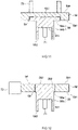
FIG. 9 is a cross sectional view along IX-IX ofFIG. 8 ; -
FIG. 10 is a view for illustrating resistance welding in manufacturing of an electrode terminal in accordance with one modified example, and showing the state in which a welding probe is in contact with the surface of a second member as seen from above the surface; -
FIG. 11 is a cross sectional view along XI-XI ofFIG. 10 ; and -
FIG. 12 is a cross sectional view schematically showing an electrode terminal in accordance with one modified example. - Below, referring to the accompanying drawings, a preferable embodiment of the technology herein disclosed will be described. Incidentally, matters necessary for executing the present invention, except for matters specifically referred to in the present specification can be grasped as design matters of those skilled in the art based on the related art in the present field. The present invention can be executed based on the contents disclosed in the present specification, and the technical common sense in the present field. Further, in the following respective drawings, the members/sites producing the same effects are given the same reference numerals and signs for description. Further, the dimensional relation in each following drawing (such as length, width, or thickness) does not reflect the actual dimensional relation.
- Incidentally, in the present specification, the term "secondary battery" is a term denoting an electric storage device capable of repeatedly charging and discharging in general, and is a concept including a so-called storage battery (chemical battery) such as a lithium ion secondary battery, a sodium ion secondary battery, or a nickel hydrogen battery, and a capacitor (physical battery) such as an electric double layer capacitor. Further, in the present specification, the term "lithium ion secondary battery" denotes a secondary battery using lithium ions as electric charge carriers, and implementing charging and discharging by the transfer of electric charges accompanying transfer of lithium ions between the positive and negative electrodes. Further, in the present specification, "A to B" means "A or more and B or less", and includes more than A and less than B. Further, in the present specification, the wording "mainly including A" denotes including A in an amount of at least 70 wt% based on the total amount of the components.
- The secondary battery herein disclosed is a repeatedly chargeable and dischargeable secondary battery, and is, for example, a lithium ion secondary battery. As shown in
FIG. 1 , asecondary battery 12 broadly has an electrode body (not shown), a nonaqueous electrolyte (not shown), and abattery case 30. Thebattery case 30 is a flat square container, and has a battery casemain body 32 in a shape of a bottomed box having an opening, and alid body 34 for sealing the opening. The casemain body 32 accommodates the electrode body and the nonaqueous electrolyte in the inside thereof. The opening of the casemain body 32 and the edge of thelid body 34 are sealed by laser welding or the like. For thebattery case 30, for example, a metal material which is lightweight and has a favorable thermal conductivity such as aluminum is used. - As shown in
FIG. 2 , anelectrode body 20 is a power generating element of thesecondary battery 12, and is accommodated in the inside of thebattery case 30 while being covered with an insulation film or the like not shown. Theelectrode body 20 is a wound electrode body including a long sheet-shapedpositive electrode sheet 21 and a long sheet-shapednegative electrode sheet 22 wound viaseparators positive electrode 21 includes a long foil-shapedpositive electrode collector 21A, and a positive electrodeactive material layer 21B formed along the longitudinal direction on one surface or both surfaces of thepositive electrode collector 21A. At one side edge of theelectrode body 20 in the long side direction of the flatsquare battery case 30 of thesecondary battery 12, there is provided a positive electrode collector exposedpart 21C at which the positive electrodeactive material layer 21B is not formed, and thepositive electrode collector 21A is exposed. Thepositive electrode collector 21A can be, for example, aluminum foil. The positive electrodeactive material layer 21B includes various materials such as a positive electrode active material, a binder, and a conductive material. Thenegative electrode 22 includes a long foil-shapednegative electrode collector 22A, and a negative electrodeactive material layer 22B formed along the longitudinal direction on one surface or both the surfaces of thenegative electrode collector 22A. Whereas, at the other side edge of theelectrode body 20 in the long side direction, there is provided a negative electrode collector exposedpart 22C at which the negative electrodeactive material layer 22B is not formed, and thenegative electrode collector 22A is exposed. Thenegative electrode collector 22A can be, for example, copper foil. The negative electrodeactive material layer 22B includes various materials such as a negative electrode active material and a binder. Theseparators positive electrode 21 and thenegative electrode 22, and for preventing the direct contact between these electrodes. As the constituent materials of the positive electrode active material layer 2lB, the negative electrodeactive material layer 22B, and the separator, the materials for use in this kind of secondary battery can be used without particular restriction, and do not characterize the present invention, and hence will not be described herein. - As shown in
FIGS. 1 to 3 , the battery case 30 (lid body 34) includes apositive electrode terminal 40 and anegative electrode terminal 50. Thepositive electrode terminal 40 includes a positiveelectrode connection terminal 44, and a positiveelectrode collector terminal 42. The positiveelectrode connection terminal 44 has a side to be arranged on the case outer surface of thelid body 34, and a site to be arranged in the case inside. The positiveelectrode connection terminal 44 is connected to the positiveelectrode collector terminal 42 in the inside of thebattery case 30. The positiveelectrode collector terminal 42 is connected to the positive electrode collector exposedpart 21C. Thenegative electrode terminal 50 includes a negativeelectrode connection terminal 54 and a negativeelectrode collector terminal 52. The negativeelectrode connection terminal 54 has a site to be arranged on the case outer surface of thelid body 34, and a site to be arranged in the case inside. The negativeelectrode connection terminal 54 is connected to the negativeelectrode collector terminal 52 in the inside of thebattery case 30. The negativeelectrode collector terminal 52 is connected to the negative electrode collector exposedpart 22C. - In the
secondary battery 12, at least any one of the positiveelectrode connection terminal 44 and the negativeelectrode connection terminal 54 includes the electrode terminal herein disclosed. Below, a description will be given to the case where the negativeelectrode connection terminal 54 is the electrode terminal herein disclosed. Incidentally, the same also applies to the case where the positiveelectrode connection terminal 44 is the electrode terminal herein disclosed, and hence a detailed description thereon will be omitted. - As shown in
FIGS. 4 and 5 , the negativeelectrode connection terminal 54 includes afirst member 56 made of a metal, and asecond member 58 made of a metal. Thefirst member 56 includes a disk-shapedconnection part 56a, and acylindrical shaft part 56b. Thesecond member 58 is formed in a flat sheet shape, and aninsertion hole 582 of a non-through concave part is formed in onesurface 581 in the thickness direction of the second member 58 (which will be also hereinafter referred to as a "lower surface 581 of thesecond member 58". The circumferential edge of theconnection part 56a of thefirst member 56 is caulked to the inner wall surface of theinsertion hole 582. Herein, the wording "the circumferential edge of theconnection part 56a of thefirst member 56 is caulked to the inner wall surface of theinsertion hole 582" denotes, for example, the state in which the circumferential edge of theconnection part 56a of thefirst member 56 is pressure welded to the inner wall surface of theinsertion hole 582, so that thefirst member 56 is fixed to thesecond member 58. As described above, theinsertion hole 582 is non-through. For this reason, theconnection part 56a is not exposed to the outside from theother surface 584 in the thickness direction (which will be also hereinafter referred to as the "upper surface 584 of thesecond member 58". For this reason, other members (e.g., the bus bar) can be more readily joined to theupper surface 584. Further, theupper surface 584 includes a single material, and hence can improve the joint strength with other members. - The circumferential edge of the
connection part 56a and the inner wall surface of theinsertion hole 582 are mutually welded at the interface therebetween, thereby forming a weldedpart 59. With theconnection part 56a inserted into the inside of theinsertion hole 582, namely, in the inside of theinsertion hole 582, the interface between thefirst member 56 and thesecond member 58 is welded, thereby reducing the resistance at the interface, and the gap between thefirst member 56 and thesecond member 58 is reduced. As a result, the conductivity from thefirst member 56 to thesecond member 58 can be improved. Further, welding at the interface between the circumferential edge of theconnection part 56a and the inner wall surface of theinsertion hole 582 is also preferable from the viewpoint of improving the joint strength between thefirst member 56 and thesecond member 58 in addition to the conductivity improvement. - Although not particularly restricted, the
first member 56 and thesecond member 58 can include aluminum, an alloy mainly including aluminum, copper, or an alloy mainly including copper. The metal forming thefirst member 56 and the metal forming thesecond member 58 may be the same, or may be different. From the viewpoint of connection with a bus bar described later, thesecond member 58 preferably includes aluminum or an alloy mainly including aluminum. From the viewpoint of connection with the negative electrode collector, the first member preferably includes copper or an alloy mainly including copper. In one preferable example, thesecond member 56 includes aluminum, and thefirst member 58 includes copper. - The negative
electrode connection terminal 54 can be broadly manufactured by stacking thefirst member 56 and thesecond member 58 one on another, and subjecting the interface between both the members to resistance welding. First, as shown inFIG. 4 , the circumferential edge of theconnection part 56a of thefirst member 56 is caulked to the inner wall surface of theinsertion hole 582. Then, theconcave part 561 of thefirst member 56 is brought into contact with a welding probe 71 (electrode), and the circumferential edge of thesecond member 58 is brought into contact with a welding probe 72 (the other electrode), thereby passing a current between thewelding probe 71 and thewelding probe 72. In that way, in the inside of theinsertion hole 582, the interface between theconnection part 56a and the inner wall surface of theinsertion hole 582 generates heat due to the resistance at the time of passing a current therethrough. The heat generation can weld the interface, and can form the weldedpart 59. Incidentally, the weldedpart 59 may only be formed on at least a part of the inner wall surface of theinsertion hole 582, and is preferably formed on the entire surface of the inner wall surface of theinsertion hole 582 from the viewpoints of conductivity improvement and the joint strength improvement. By performing resistance welding while appropriately moving thewelding probe 72 along the circumferential edge of thesecond member 58, the weldedpart 59 can be formed entirely on the inner wall surface of theinsertion hole 582. By using resistance welding, it is possible to weld both the members without forming a welding mark on the surface of thesecond member 58. Especially, implementation of welding of thefirst member 56 and thesecond member 58 without formation of a welding mark on theupper surface 584 is preferable for joining other members (such as a bus bar) to theupper surface 584. Incidentally, the conditions of resistance welding (such as the magnitude of the welding current and the welding time) have no particular restriction, and can be appropriately changed. - Then, a description will be given to mounting of the negative
electrode connection terminal 54 with the foregoing configuration to the secondary battery. As shown inFIG. 5 , in thesecondary battery 12, from the outside of thebattery case 30, theshaft part 56b of thefirst member 56 is inserted into through holes respectively provided in respective members in the order of agasket 60, alid body 34, aninsulator 61, and the negativeelectrode collector terminal 52, and atip 562 is caulked in the inside of thebattery case 30. A caulked part in a ring shape in a plan view is formed at the circumferential edge portion of the though hole of the negativeelectrode collector terminal 52. Thegasket 60 is a member for insulating the negativeelectrode connection terminal 54 and thelid body 34, and is formed of a material having an insulation property (e.g., a fluorine resin such as perfluoroalkoxy alkane (PFA)). Theinsulator 61 is a member for insulating thelid body 34 and the negativeelectrode collector terminal 52, and is formed of a material having an insulation property and an electrolyte resistance (e.g., a resin material such as polyphenylene sulfide resin (PPS)). - The
secondary battery 12 can be used as a single cell forming an assembled battery as shown inFIG. 6 . As shown, an assembledbattery 100 broadly includes a plurality of secondary batteries 12 (which will also be hereinafter referred to as "single cells 12"), aspacer 11, abus bar 14, and anend plate 17. The plurality ofsingle cells 12 are arranged along a prescribed direction with thespacers 11 each interposed between respective single cells so that the flat surfaces of thesingle cells 12 are opposed to each other. Theend plates 17 are arranged at the opposite ends in the array direction of thesingle cells 12, respectively, and sandwich the plurality of arrayedsingle cells 12 in the same direction.Respective end plates 17 are bridged by a bindingband 18 made of a metal, and the end of the bindingband 18 is fastened and fixed by ascrew 19. - As shown, the
positive electrode terminal 40 of onesingle cell 12 and thenegative electrode terminal 50 of the othersingle cell 12 adjacent to the single cell are electrically connected with each other by the flat sheet-shapedbus bar 14. Thebus bar 14 is welded to the positiveelectrode connection terminal 44 and the negativeelectrode connection terminal 54 by laser welding, or the like. As shown inFIG. 7 , thebus bar 14 is welded to theupper surface 584 of thesecond member 58, so that a weldedpart 14a is formed. Thebus bar 14 and thesecond member 58 have no particular restriction so long as both the members can be joined with each other with a sufficient strength. From the viewpoint of improving the conductivity between thebus bar 14 and thenegative electrode terminal 50, the distance between the weldedpart 14a of thebus bar 14 and thesecond member 58, and the weldedpart 59 of thefirst member 56 and thesecond member 58 is preferably shortened. In the direction orthogonal to the plane direction of the bottom surface of the battery case 30 (i.e., the extension direction of theshaft part 56b), thebus bar 14 and thesecond member 58 are preferably welded on a substantially vertical line to the weldedpart 59 between thefirst member 56 and thesecond member 58. Herein, in the present specification, the wording "being welded on a substantially vertical line" denotes that the weldedpart 14a between thebus bar 14 and thesecond member 58 is formed above the circular region with a radius of 5 mm or less (preferably 3 mm or less) with the weldedpart 59 between thefirst member 56 and thesecond member 58 as the center. - The
bus bar 14 can include a metal such as aluminum, copper, nickel, or stainless steel. From the viewpoint of improving the joint strength and the conductivity with thesecond member 58, thebus bar 14 preferably includes the same metal as the metal of thesecond member 58. For example, when thesecond member 58 is made of aluminum, thebus bar 14 is preferably also made of aluminum. Incidentally, the shape of thebus bar 14 has no particular restriction. For example, a cylindrical one may be used. - The assembled
battery 100 is usable for various uses, and can be preferably used as, for example, a power source (driving power supply) for a motor to be mounted on a car. The kind of the car has no particular restriction. Typically, mention may be made of a vehicle such as a Plug-in hybrid Electric Vehicle (PHEV), a Hybrid Electric Vehicle (HEV), or an electric vehicle (EV). - Up to this point, specific examples of the present invention have been described in details. However, the embodiments are merely illustrative, and should not be construed as limiting the scope of the appended claims. The technology described in the appended claims includes various modifications and changes of the specific examples shown up to this point. Also in the modified examples shown below, the same effects as those of the embodiments can be obtained. For example, in the embodiments, the circumferential edge of the
connection part 56a of thefirst member 56 is caulked to the inner wall surface of theinsertion hole 582. However, the present invention is not limited thereto, and caulking is not required to be performed. In this case, with the connection part inserted into the insertion hole, resistance welding is performed. As a result, it is possible to perform welding of the first member and the second member. - Further, in the embodiment, for joining the
first member 56 and thesecond member 58, the welding probe was brought into contact with each of theconcave part 561 of thefirst member 56 and the circumferential edge of thesecond member 58, but the present invention is not limited thereto. As shown inFIGS. 8 and9 , with thewelding probe 71 brought into contact with theconcave part 561 of thefirst member 56, and with thewelding probe 72 brought into contact with theupper surface 584 of thesecond member 58, resistance welding may be performed. In this case, the weldedpart 59 can be formed substantially vertically under thewelding probe 72. As a result of this, it is possible to reduce the gap at the interface between thefirst member 56 and thesecond member 58. Further, a welding mark is not formed on theupper surface 584. For this reason, it is possible to perform welding of theupper surface 584 and thebus bar 14 with ease, and it is possible to improve the joint strength. Incidentally, the contact site of thewelding probe 72 is not limited to the site shown inFIGS. 8 and9 , and may be appropriately moved, if required. - Alternatively, as shown in
FIGS. 10 and11 , as thewelding probe 72, the one in a ring-shape in cross section may be used. In this case, the weldedpart 59 can be formed substantially vertically under thewelding probe 72. In the present modified example, from the viewpoint of preventing the deviation of the surface pressure from thewelding probe 72 applied on theupper surface 584 of thesecond member 58, thewelding probe 71 is preferably arranged at the position such that the distances from thewelding probe 72 are equal. - Further, in the embodiment, the
insertion hole 582 is a non-through concave part. However, the present invention is not limited thereto, and a through hole is also acceptable. As shown inFIG. 12 , thetip 563 outside thebattery case 30 in the insertion direction of theconnection part 56a into theinsertion hole 582 can be more exposed to the outside than theupper surface 584 of thesecond member 58. For joining thefirst member 56 and thesecond member 58, with thewelding probe 71 brought into contact with theconcave part 561 of thefirst member 56, and with thewelding probe 72 brought into contact with the circumferential edge of thesecond member 58, resistance welding is performed. As a result, the weldedpart 59 can be formed at the site shown. Incidentally, caulking processing may be carried out in which thetip 563 of thefirst member 56 is more protruded to the outside than theupper surface 584 of thesecond member 58 for compressive deformation into a hat shape. - Further, in the embodiment, the diameter of the
connection part 56a in a plan view is larger than the diameter of theshaft part 56b. However, the present invention is not limited thereto. The diameter of theconnection part 56a and the diameter of theshaft part 56b may be set to be equal to each other.
Claims (7)
- An electrode terminal (54) of a secondary battery (12), comprising:a first member (56) made of a metal, and a second member (58) made of a metal;wherein the first member (56) has a connection part (56a) to be connected with the second member (58),the second member (58) has an insertion hole (582) for allowing the connection part (56a) of the first member (56) to be inserted thereinto, andthe first member (56) and the second member (58) are welded to each other at an interface between the first member (56) and the second member (58) situated in an inside of the insertion hole (582).
- The electrode terminal (54) according to claim 1,
wherein the first member (56) and the second member (58) comprise mutually different metals. - The electrode terminal (54) according to claim 1 or 2,
wherein the insertion hole (582) is a non-through concave part formed in one surface (581) of the second member (58). - The electrode terminal (54) according to any one of claims 1 to 3,wherein the connection part (56a) is formed in a disk shape, anda circumferential edge of the connection part (56a) is caulked to an inner wall surface of the insertion hole (582).
- A secondary battery (12), comprising:an electrode body (20) having a positive electrode and a negative electrode;a battery case (30) for accommodating the electrode body (20);a positive electrode terminal (40) mounted on the positive electrode; anda negative electrode terminal (50) mounted on the negative electrode,wherein at least any one of the positive electrode terminal (40) and the negative electrode terminal (50) comprises the electrode terminal (54) according to any one of claims 1 to 4.
- An assembled battery (100) comprising a plurality of single cells mutually electrically connected, and arrayed therein, and comprising:
the secondary battery (12) according to claim 5 as the single cell. - The assembled battery (100) according to claim 6, comprising:a bus bar (14) for establishing an electrical connection between the arrayed single cells,wherein the bus bar (14) is welded in surface contact with a surface (584) of the second member (58) of each of the connected single cells, andin a direction orthogonal to a surface direction of a bottom surface of the battery case (30), the bus bar (14) and the second member (58) are welded on a substantially vertical line of a welded part between the first member (56) and the second member (58).
Applications Claiming Priority (1)
| Application Number | Priority Date | Filing Date | Title |
|---|---|---|---|
| JP2021015329A JP7296996B2 (en) | 2021-02-02 | 2021-02-02 | Electrode terminal and its use |
Publications (2)
| Publication Number | Publication Date |
|---|---|
| EP4037088A2 true EP4037088A2 (en) | 2022-08-03 |
| EP4037088A3 EP4037088A3 (en) | 2022-12-14 |
Family
ID=80001605
Family Applications (1)
| Application Number | Title | Priority Date | Filing Date |
|---|---|---|---|
| EP22152967.0A Pending EP4037088A3 (en) | 2021-02-02 | 2022-01-24 | Electrode terminal and use thereof |
Country Status (4)
| Country | Link |
|---|---|
| US (1) | US20220247045A1 (en) |
| EP (1) | EP4037088A3 (en) |
| JP (2) | JP7296996B2 (en) |
| CN (1) | CN114843670A (en) |
Citations (1)
| Publication number | Priority date | Publication date | Assignee | Title |
|---|---|---|---|---|
| US9680136B2 (en) | 2014-06-17 | 2017-06-13 | Samsung Sdi Co., Ltd. | Rechargeable battery |
Family Cites Families (9)
| Publication number | Priority date | Publication date | Assignee | Title |
|---|---|---|---|---|
| US7892674B2 (en) * | 2005-09-09 | 2011-02-22 | Kabushiki Kaisha Toshiba | Nonaqueous electrolyte secondary battery and battery module |
| US8956753B2 (en) * | 2010-03-30 | 2015-02-17 | Samsung Sdi Co., Ltd. | Secondary battery and secondary battery module |
| KR101223521B1 (en) * | 2010-08-16 | 2013-01-17 | 로베르트 보쉬 게엠베하 | Rechargeable battery |
| JP6024095B2 (en) * | 2010-12-10 | 2016-11-09 | 株式会社Gsユアサ | Electric storage element, method for manufacturing electric storage element, and method for manufacturing terminal |
| WO2013018841A1 (en) * | 2011-08-04 | 2013-02-07 | 株式会社Neomaxマテリアル | Negative-electrode terminal for cell |
| CN106575741A (en) * | 2014-08-06 | 2017-04-19 | 日立汽车系统株式会社 | Rectangular secondary battery |
| JP6529806B2 (en) * | 2015-03-31 | 2019-06-12 | 三洋電機株式会社 | Secondary battery and assembled battery |
| JP6427460B2 (en) * | 2015-04-22 | 2018-11-21 | 日立オートモティブシステムズ株式会社 | Square secondary battery |
| JP7334198B2 (en) * | 2021-02-01 | 2023-08-28 | プライムプラネットエナジー&ソリューションズ株式会社 | Electrode terminal and secondary battery provided with the electrode terminal |
-
2021
- 2021-02-02 JP JP2021015329A patent/JP7296996B2/en active Active
-
2022
- 2022-01-24 EP EP22152967.0A patent/EP4037088A3/en active Pending
- 2022-01-28 CN CN202210103886.7A patent/CN114843670A/en active Pending
- 2022-01-31 US US17/589,646 patent/US20220247045A1/en active Pending
-
2023
- 2023-04-19 JP JP2023068809A patent/JP2023089231A/en active Pending
Patent Citations (1)
| Publication number | Priority date | Publication date | Assignee | Title |
|---|---|---|---|---|
| US9680136B2 (en) | 2014-06-17 | 2017-06-13 | Samsung Sdi Co., Ltd. | Rechargeable battery |
Also Published As
| Publication number | Publication date |
|---|---|
| JP2023089231A (en) | 2023-06-27 |
| US20220247045A1 (en) | 2022-08-04 |
| JP2022118648A (en) | 2022-08-15 |
| EP4037088A3 (en) | 2022-12-14 |
| JP7296996B2 (en) | 2023-06-23 |
| CN114843670A (en) | 2022-08-02 |
Similar Documents
| Publication | Publication Date | Title |
|---|---|---|
| US8815426B2 (en) | Prismatic sealed secondary cell and method of manufacturing the same | |
| US10062871B2 (en) | Rechargeable battery with tabs | |
| EP3972042A1 (en) | Terminal for secondary battery and method for manufacturing terminal for secondary battery | |
| EP3972044A1 (en) | Secondary battery and terminal for secondary battery and manufacturing method thereof | |
| US20130122355A1 (en) | Rechargeable battery | |
| KR20210092094A (en) | The Apparatus And The Method For Folding Electrode Tab | |
| JP2018067381A (en) | Power storage device | |
| KR20180085446A (en) | Battery Pack Comprising Electrode Terminal Connecting Plate | |
| US10991985B2 (en) | Secondary battery | |
| US20140023913A1 (en) | Prismatic secondary battery | |
| EP3506408B1 (en) | Electrode assembly, and secondary battery comprising same | |
| US20120321942A1 (en) | Electrode assembly and secondary battery using the same | |
| US12087972B2 (en) | Sealed battery | |
| JP2019160529A (en) | Sealed battery | |
| KR100612236B1 (en) | Secondary battery and electrodes assembly | |
| EP4037088A2 (en) | Electrode terminal and use thereof | |
| KR102641236B1 (en) | Terminal for secondary battery and secondary battery provided with the terminal | |
| EP4057439A1 (en) | Terminal component and electricity storage device | |
| KR101431726B1 (en) | Electrode Assembly of Improved Safety And Secondary Battery with the Same | |
| EP3926751B1 (en) | Secondary battery with specific current collecting member, battery module and device | |
| KR20220119699A (en) | Electrode assembly, battery cell, battery, power consumption device, manufacturing method and equipment | |
| US12100865B2 (en) | Terminal for secondary battery and secondary battery provided with the terminal | |
| JP7285817B2 (en) | SEALED BATTERY AND METHOD OF MANUFACTURING SEALED BATTERY | |
| US20240283106A1 (en) | Battery Cell and Manufacturing Method Thereof | |
| KR20230132286A (en) | Cylindrical secondary battery cell, and battery pack and vehicle including the same |
Legal Events
| Date | Code | Title | Description |
|---|---|---|---|
| PUAI | Public reference made under article 153(3) epc to a published international application that has entered the european phase |
Free format text: ORIGINAL CODE: 0009012 |
|
| STAA | Information on the status of an ep patent application or granted ep patent |
Free format text: STATUS: REQUEST FOR EXAMINATION WAS MADE |
|
| 17P | Request for examination filed |
Effective date: 20220124 |
|
| AK | Designated contracting states |
Kind code of ref document: A2 Designated state(s): AL AT BE BG CH CY CZ DE DK EE ES FI FR GB GR HR HU IE IS IT LI LT LU LV MC MK MT NL NO PL PT RO RS SE SI SK SM TR |
|
| PUAL | Search report despatched |
Free format text: ORIGINAL CODE: 0009013 |
|
| AK | Designated contracting states |
Kind code of ref document: A3 Designated state(s): AL AT BE BG CH CY CZ DE DK EE ES FI FR GB GR HR HU IE IS IT LI LT LU LV MC MK MT NL NO PL PT RO RS SE SI SK SM TR |
|
| RIC1 | Information provided on ipc code assigned before grant |
Ipc: H01M 50/103 20210101ALI20221110BHEP Ipc: H01M 50/566 20210101ALI20221110BHEP Ipc: H01M 50/557 20210101ALI20221110BHEP Ipc: H01M 50/516 20210101AFI20221110BHEP |