EP4382938A1 - Method for estimating dcir of battery and battery system providing same - Google Patents
Method for estimating dcir of battery and battery system providing same Download PDFInfo
- Publication number
- EP4382938A1 EP4382938A1 EP22893150.7A EP22893150A EP4382938A1 EP 4382938 A1 EP4382938 A1 EP 4382938A1 EP 22893150 A EP22893150 A EP 22893150A EP 4382938 A1 EP4382938 A1 EP 4382938A1
- Authority
- EP
- European Patent Office
- Prior art keywords
- value
- battery pack
- pack
- battery
- target
- Prior art date
- Legal status (The legal status is an assumption and is not a legal conclusion. Google has not performed a legal analysis and makes no representation as to the accuracy of the status listed.)
- Granted
Links
Images


Classifications
-
- G—PHYSICS
- G01—MEASURING; TESTING
- G01R—MEASURING ELECTRIC VARIABLES; MEASURING MAGNETIC VARIABLES
- G01R31/00—Arrangements for testing electric properties; Arrangements for locating electric faults; Arrangements for electrical testing characterised by what is being tested not provided for elsewhere
- G01R31/36—Arrangements for testing, measuring or monitoring the electrical condition of accumulators or electric batteries, e.g. capacity or state of charge [SoC]
- G01R31/389—Measuring internal impedance, internal conductance or related variables
-
- G—PHYSICS
- G01—MEASURING; TESTING
- G01R—MEASURING ELECTRIC VARIABLES; MEASURING MAGNETIC VARIABLES
- G01R19/00—Arrangements for measuring currents or voltages or for indicating presence or sign thereof
- G01R19/0038—Circuits for comparing several input signals and for indicating the result of this comparison, e.g. equal, different, greater, smaller (comparing pulses or pulse trains according to amplitude)
-
- G—PHYSICS
- G01—MEASURING; TESTING
- G01R—MEASURING ELECTRIC VARIABLES; MEASURING MAGNETIC VARIABLES
- G01R19/00—Arrangements for measuring currents or voltages or for indicating presence or sign thereof
- G01R19/10—Measuring sum, difference or ratio
-
- G—PHYSICS
- G01—MEASURING; TESTING
- G01R—MEASURING ELECTRIC VARIABLES; MEASURING MAGNETIC VARIABLES
- G01R31/00—Arrangements for testing electric properties; Arrangements for locating electric faults; Arrangements for electrical testing characterised by what is being tested not provided for elsewhere
- G01R31/36—Arrangements for testing, measuring or monitoring the electrical condition of accumulators or electric batteries, e.g. capacity or state of charge [SoC]
- G01R31/367—Software therefor, e.g. for battery testing using modelling or look-up tables
-
- G—PHYSICS
- G01—MEASURING; TESTING
- G01R—MEASURING ELECTRIC VARIABLES; MEASURING MAGNETIC VARIABLES
- G01R31/00—Arrangements for testing electric properties; Arrangements for locating electric faults; Arrangements for electrical testing characterised by what is being tested not provided for elsewhere
- G01R31/36—Arrangements for testing, measuring or monitoring the electrical condition of accumulators or electric batteries, e.g. capacity or state of charge [SoC]
- G01R31/382—Arrangements for monitoring battery or accumulator variables, e.g. SoC
- G01R31/3842—Arrangements for monitoring battery or accumulator variables, e.g. SoC combining voltage and current measurements
-
- G—PHYSICS
- G01—MEASURING; TESTING
- G01R—MEASURING ELECTRIC VARIABLES; MEASURING MAGNETIC VARIABLES
- G01R31/00—Arrangements for testing electric properties; Arrangements for locating electric faults; Arrangements for electrical testing characterised by what is being tested not provided for elsewhere
- G01R31/36—Arrangements for testing, measuring or monitoring the electrical condition of accumulators or electric batteries, e.g. capacity or state of charge [SoC]
- G01R31/396—Acquisition or processing of data for testing or for monitoring individual cells or groups of cells within a battery
-
- G—PHYSICS
- G01—MEASURING; TESTING
- G01R—MEASURING ELECTRIC VARIABLES; MEASURING MAGNETIC VARIABLES
- G01R31/00—Arrangements for testing electric properties; Arrangements for locating electric faults; Arrangements for electrical testing characterised by what is being tested not provided for elsewhere
- G01R31/36—Arrangements for testing, measuring or monitoring the electrical condition of accumulators or electric batteries, e.g. capacity or state of charge [SoC]
- G01R31/392—Determining battery ageing or deterioration, e.g. state of health
Definitions
- the present invention relates to a method for estimating a resistance of a battery and a battery system for providing the method.
- Batteries that may be repeatedly charged and discharged have come into prominence as an alternative to fossil energy. Batteries have been mainly used in traditional handheld devices, such as mobile phones, video cameras, and power tools. However, in recent years, application fields of batteries tend to gradually expand to electric vehicles (EV, HEV, PHEV) that are driven by electricity, large-capacity energy storage systems (ESS), and uninterruptible power supply systems (UPS).
- EV electric vehicles
- HEV high-capacity energy storage systems
- UPS uninterruptible power supply systems
- a state of health may be different between a battery pack that has already been installed and used for a predetermined period (hereinafter, referred to as an "old battery pack") and a newly mounted battery pack (hereinafter, referred to as a "new battery pack").
- the present invention provides a method for estimating a resistance of a battery for estimating a direct current internal resistance (DCIR), which is one of the factors indicating a state of health (SOH) of a battery pack, and a battery system providing the method.
- DCIR direct current internal resistance
- An example embodiment of the present invention provides a battery system including a battery including a new battery pack having a known internal resistance value and a target battery pack having an internal resistance value to be estimated, and a master battery management system (BMS) configured to estimate a target resistance value of the target battery pack based on at least one of a current value of a first compensation current flowing from the new battery pack to the target battery pack when the new battery pack and the target battery pack are connected in parallel, a new resistance value of the new battery pack, a current value of a second compensation current corresponding to a first pack voltage difference value of the new battery pack and the target battery pack, a first reference resistance value, and a second reference resistance value.
- BMS master battery management system
- the second compensation current may be a compensation current flowing when a first reference battery pack and a second reference battery pack having a second pack voltage difference value equal to the first pack voltage difference value are connected in parallel
- the first reference resistance value may be a value of an internal resistance of the first reference battery pack
- the second reference resistance value may be a value of an internal resistance of the second reference battery pack.
- the battery system may further include: a memory configured to store a look-up table having mapped and recorded therein a current value of the second compensation current corresponding to each of a plurality of second pack voltage difference values including the second pack voltage difference value, and the first reference resistance value and the second reference resistance value.
- the master BMS may select a second pack voltage difference value having a same voltage value as that of the first pack voltage difference value from among the plurality of second pack voltage difference values, and estimate the target resistance value of the target battery pack by extracting the current value of the second compensation current mapped to the second pack voltage difference value, the first reference resistance value, and the second reference resistance value.
- Each of the new battery pack and the target battery pack may include: a battery module including a plurality of battery cells, a voltage sensor configured to measure a pack voltage, which is a voltage across the battery module, and a current sensor configured to measure a pack current flowing in the battery module; and a pack switch connecting the battery module to the battery system in parallel through an ON operation, and a slave BMS configured to transmit measurement results from the voltage sensor and the current sensor by communicating with the master BMS and receive a control signal for controlling a switching operation of the pack switch.
- the master BMS may receive a first pack voltage value of the new battery pack and a second pack voltage value of the target battery pack measured before the new battery pack and the target battery pack are connected in parallel, and the current value of the first compensation current measured after the new battery pack and the target battery pack are connected in parallel, and calculate the first pack voltage difference value, which is a difference value between the first pack voltage value and the second pack voltage value.
- Another example embodiment of the present invention provides a method for estimating a battery resistance to estimate an internal resistance value of a target battery pack in a battery system including a new battery pack having a known internal resistance value and a plurality of old battery packs having internal resistance values be estimated, including: selecting the target battery pack from among the plurality of old battery packs according to a predetermined criterion; connecting the new battery pack and the target battery pack in parallel; receiving a current value of a first compensation current flowing between the new battery pack and the target battery pack connected in parallel, a first pack voltage value of the new battery pack, and a second pack voltage value of the target battery pack; and estimating a target resistance value of the target battery pack based on at least one of a current value of the first compensation current, a new resistance value of the new battery pack, a current value of a second compensation current corresponding to a first pack voltage difference between the new battery pack and the target battery pack, a first reference resistance value, and a second reference resistance value.
- the second compensation current may be a compensation current flowing when a first reference battery pack and a second reference battery pack having a second pack voltage difference value equal to the first pack voltage difference value are connected in parallel, the first reference resistance value is a value of an internal resistance of the first reference battery pack, and the second reference resistance value is a value of an internal resistance of the second reference battery pack.
- the estimating of the target resistance value of the target battery pack may include: calculating the first pack voltage difference value, which is a difference value between the first pack voltage value and the second pack voltage value; and extracting the current value of the second compensation current corresponding to the second pack voltage difference value, which is a same voltage value as the first pack voltage difference value, the first reference resistance value, and the second reference resistance value, from a look-up table.
- the receiving of the current value of the first compensation current may include receiving the first pack voltage value of the new battery pack and the second pack voltage value of the target battery pack measured before the new battery pack and the target battery pack are connected in parallel, and the current value of the first compensation current measured after the new battery pack and the target battery pack are connected in parallel.
- DCIR direct current internal resistance
- the internal resistance (DCIR) of each of the old battery packs may be estimated with high precision.
- FIG. 1 is a diagram illustrating a battery system A for estimating resistance of a battery according to an example embodiment
- FIG. 2 is a diagram specifically illustrating a configuration of a battery pack of FIG. 1
- FIGS. 3 to 5 are conceptual views illustrating a method of measuring internal resistance of an old battery pack by connecting a new battery pack and one of old battery packs, among a plurality of battery packs, in parallel.
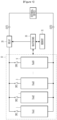
- the battery system A includes a battery 10, a relay 20, and a master battery management system (BMS) 30.
- BMS master battery management system
- the battery 10 includes a plurality of battery packs 1 to N (or 1-N) and a plurality of pack switches SW1 to SWN respectively connecting the plurality of battery packs 1-N to the battery system A in parallel.
- reference numeral "j" when indicating a specific battery pack among the plurality of battery packs 1-N, reference numeral "j" is used, and a battery module, a voltage sensor, a slave BMS, and a pack switch included in the corresponding battery pack j respectively use reference numerals "j1", “j3", "j5", and "PSWj".
- reference numeral "SWj" is used to indicate a specific pack switch that connects a specific battery pack j, among the plurality of pack switches SW1 to SWN, to the battery system A in parallel.
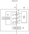
- the battery pack j may include a battery module 100j, a voltage sensor 200j, a current sensor 300j, a slave BMS 400j, and a pack switch SWj.
- the battery pack j is illustrated as not including the pack switch SWj, but the present invention is not limited thereto, and the pack switch SWj corresponding to any battery pack j may be described as being included in the corresponding the battery pack j.
- the battery module 100j may include a plurality of battery cells connected in series and/or in parallel.
- the battery cell may be a rechargeable secondary battery.
- FIG. 2 a battery module 100j including three battery cells Cell1 to Cell3 connected in series is shown, but is not limited thereto.
- the battery module 100j may include various numbers of battery cells.
- the voltage sensor 200j is connected in parallel with the battery module 100j.
- the voltage sensor 200j may measure a pack voltage Vj, which is a voltage across the battery module 100j, and transmit a measurement result to the master BMS 30 through the slave BMS 400j.
- the current sensor 300j is connected in series with the battery module 100j.
- the current sensor 300j may measure a pack current Ij flowing through the battery module 100j and transmit a measurement result to the master BMS 30 through the slave BMS 400j.
- the slave BMS 400j may transmit data including various information on the battery cell, the pack voltage Vj and pack current Ij (where j is 1 to N) and receive various commands through communication with the master BMS 30.
- the slave BMS 400j may receive a control signal for controlling a switching (ON/OFF) operation of the pack switch SWj.
- the relay 20 may electrically connect or disconnect the battery system (A) and the external device (B). Specifically, when the relay unit 20 electrically connects the battery system A and the external device B, the battery 10 may be charged with power from the external device B or supply power to the external device B.
- the external device B may be a charger in a charging mode in which the battery 10 is charged, and a load (e.g., a vehicle motor, etc.) in a discharging mode in which the battery 10 is discharged.
- the relay 20 may be turned off. Then, the master BMS 30 may estimate the internal resistance (DCIR) of the battery pack j with high precision, without being affected by the external device B.
- DCIR direct current internal resistance
- the master BMS 30 may select a target battery pack whose internal resistance (DCIR) needs to be estimated, among a plurality of old battery packs.
- DCIR internal resistance
- the master BMS 30 includes a memory storing a look-up table in which current values of a plurality of second compensation current respectively corresponding to a plurality of second pack voltage difference values and a reference resistance value are mapped and recorded.
- the look-up table may be stored in the memory 31 in the form of Table 1 to be described below.
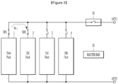
- the first battery pack 1 is a replaced new battery pack and second to fourth battery packs 2 to 4 are old battery packs.
- the new battery pack is an unused battery pack and may be a battery pack whose internal resistance value is known.
- the old battery pack may be a battery pack in which the battery system A is installed and used for a predetermined period of time, and may be a battery pack whose internal resistance value is not known.
- the master BMS 30 may select a target battery pack whose internal resistance value is to be estimated, among the second to fourth battery packs 2 to 4 that are a plurality of old battery packs, according to a predetermined criterion.
- the master BMS 30 may turn on each pack switch SWj so that the target battery pack and the new battery pack are connected in parallel.
- the master BMS 30 may estimate internal resistance (DCIR) of the target battery pack based on the pack voltage Vj of each of the target battery pack and the new battery pack and the current value of the compensation current Im flowing between the target battery pack and the new battery pack connected in parallel. Details thereof will be described below with reference to FIGS. 3 to 6 .
- FIG. 6 is a diagram illustrating a method of estimating resistance of a battery according to an example embodiment.
- the master BMS 30 communicates with an upper controller (not shown) and receives a message instructing that a new battery pack is loaded in the battery system A
- the master BSM 30 performs an internal resistance (DCIR) estimation logic on the old battery pack (S100).
- DCIR internal resistance
- the first battery pack 1 is a replaced new battery pack and the second to fourth battery packs 2 to 4 are old battery packs.
- the present invention is not limited thereto, and the battery 10 may include various numbers of old battery packs and new battery packs.
- the master BMS 30 selects a target battery pack from among the plurality of old battery packs 2 to 4 according to a predetermined criterion (S200).
- the master BMS 30 may select a target battery pack in the order of the second battery pack 2, the third battery pack 3, and the fourth battery pack 4.
- the present invention is not limited thereto, and the master BMS 30 may apply various criteria, such as randomly selecting the second to fourth battery packs 2 to 4 as target battery packs.
- the master BMS 30 connects the new battery pack 1 and the target battery pack j in parallel (S300).
- the master BMS 30 connect the first battery pack 1 and the second battery pack 2 in parallel by turning on the first pack switch SW1 of the first battery pack 1 that is a new battery and the second pack switch SW2 of the second battery pack 2 that is a target battery pack.
- a next target battery pack, the third battery pack 3, and a new battery, the first battery pack 1, may be connected in parallel.
- the master BMS 30 may connect the first battery pack 1 and the third battery pack 3 in parallel by turning on the first pack switch SW1 and the third pack switch SW3.
- the fourth battery pack 4 as the next target battery pack and the first battery 1 as the new battery pack may be connected in parallel.
- the master BMS 30 may connect the first battery pack 1 and the fourth battery pack 4 in parallel by turning on the first pack switch SW1 and the fourth pack switch SW4.
- the master BMS 30 receives a pack current value and a pack voltage value from each of the new battery pack and the target battery pack (S400).
- the master BMS 30 receives a first pack current I1 value and a first pack voltage V1 value from the first battery pack 1.
- the master BMS 30 receives the second pack current I2 value and the second pack voltage V2 value from the second battery pack 2.
- the first pack current I1 is a first compensation current Im flowing between the first battery pack 1 and the second battery pack 2 connected in parallel.
- the second pack current I2 is the first compensation current Im flowing between the first battery pack 1 and the second battery pack 2 connected in parallel. That is, when the first compensation current Im is measured in the first battery pack 1, the first compensation current Im may be the first pack current I1, and when the first pack current I1 is measured in the second battery pack 2, the first pack current I1 may be the second pack current I2.
- first pack voltage V1 and the second pack voltage V2 may be pack voltages measured before the first battery pack 1 and the second battery pack 2 are connected in parallel.
- first compensation current Im flows due to a first pack voltage difference ⁇ Vs.
- the voltage values of the respective pack voltages of the first battery pack 1 and the second battery pack 2 may be the same.
- the master BMS 30 estimates a resistance value of the target resistance (Rold_t), which is the internal resistance (DCIR) of the target battery pack, based on the current value of the first compensation current Im, the current value of the second compensation current Idiff, the resistance value of the new resistor Rnew, the resistance value of the first reference resistor Rref_1, and the resistance value of the second reference resistance Rref_2 (S500).
- a compensation current is a current generated by a voltage difference between battery packs, and is a current flowing to match voltage values between battery packs connected in parallel.
- the first compensation current Im is a compensation current flowing between a new battery pack and a target battery pack connected in parallel.
- the second compensation current Idiff is a compensation current flowing between the first and second reference battery packs having a second pack voltage difference value ⁇ Vd that is the same voltage value as the first pack voltage difference value ⁇ Vs between the new battery pack and the target battery pack.
- the current value e.g., 5A
- the first pack voltage difference value ⁇ Vs may be a difference value between pack voltages of the new battery pack and the target battery pack.
- the second pack voltage difference ⁇ Vd may be a difference value between pack voltages of the first standard battery pack and the second standard battery pack.
- Table 1 below shows the look-up table in which the current value of the second compensation current Idiff, corresponding to the difference value ⁇ Vd of the second pack voltage, the resistance values of the first reference resistor Rref_1, and the second reference resistor Rref_2 are mapped and recorded.
- Table 1 Second pack voltage difference value ( ⁇ Vd) Second compensation current (Idiff) First reference resistance (Rref_1) Second reference resistance (Rref_2) 1V 1 a R a1 R a2 2V 1 b R b1 R b2 3V 1 c R c1 R c2 ... ... ... ... 20V 5A 2 ⁇ 2 ⁇ ... ... ... ... ... ...
- the first pack voltage difference ⁇ Vs represents the product of the first compensation current Im and the combined internal resistance Rold_t + Rnew of the battery packs connected in parallel.
- the current value of the first compensation current Im may be a current value measured in the battery pack
- the resistance value of the new resistor Rnew may be a known resistance value.
- the second pack voltage difference value ⁇ Vd represents the product of the second compensation current Idiff and the combined internal resistance (Rref_1 + Rref_2) of the battery packs connected in parallel.
- the current value of the second compensation current (Id), the resistance value of the first reference resistor Rref_1, and the resistance value of the second reference resistor Rref_2 are values that may be known through the look-up table.
- Equation (1) above may be expressed as E equation (4) below.
- the master BMS 30 may estimate the resistance value of the target resistance Rold_t as 8 ⁇ .
- the master BMS 30 determines whether there is an old battery pack whose internal resistance value needs to be estimated (S600).
- the process repeats again from S200 described above.
- the master BMS 30 may select the third battery pack 3 as a target battery pack.
- the master BMS 30 may select the fourth battery pack 4 as a target battery pack.
- the master BMS 30 terminates the estimation logic of the internal resistance value.
Landscapes
- Physics & Mathematics (AREA)
- General Physics & Mathematics (AREA)
- Secondary Cells (AREA)
- Tests Of Electric Status Of Batteries (AREA)
- Measurement Of Resistance Or Impedance (AREA)
- Charge And Discharge Circuits For Batteries Or The Like (AREA)
Abstract
Description
- This application claims benefit of priority to
Korean Patent Application No. 10-2021-0155537 filed on November 12, 2021 - The present invention relates to a method for estimating a resistance of a battery and a battery system for providing the method.
- Batteries that may be repeatedly charged and discharged have come into prominence as an alternative to fossil energy. Batteries have been mainly used in traditional handheld devices, such as mobile phones, video cameras, and power tools. However, in recent years, application fields of batteries tend to gradually expand to electric vehicles (EV, HEV, PHEV) that are driven by electricity, large-capacity energy storage systems (ESS), and uninterruptible power supply systems (UPS).
- In the case of a battery, when capacity decreases, resistance may increase, thereby increasing electrical energy lost as heat. Therefore, when the capacity of the battery decreases below a critical value, the performance of the battery may significantly deteriorate and the amount of generated heat may increase, requiring inspection or replacement.
- Meanwhile, in a battery system A including a plurality of battery packs connected in parallel, and in the case of replacing some of the plurality of battery packs having a lowered performance, a state of health (SOH) may be different between a battery pack that has already been installed and used for a predetermined period (hereinafter, referred to as an "old battery pack") and a newly mounted battery pack (hereinafter, referred to as a "new battery pack").
- In this case, it is necessary to know exactly how much the old battery pack has deteriorated in order to plan an operational strategy for efficiently using the newly installed new battery pack and the old battery pack.
- The present invention provides a method for estimating a resistance of a battery for estimating a direct current internal resistance (DCIR), which is one of the factors indicating a state of health (SOH) of a battery pack, and a battery system providing the method.
- An example embodiment of the present invention provides a battery system including a battery including a new battery pack having a known internal resistance value and a target battery pack having an internal resistance value to be estimated, and a master battery management system (BMS) configured to estimate a target resistance value of the target battery pack based on at least one of a current value of a first compensation current flowing from the new battery pack to the target battery pack when the new battery pack and the target battery pack are connected in parallel, a new resistance value of the new battery pack, a current value of a second compensation current corresponding to a first pack voltage difference value of the new battery pack and the target battery pack, a first reference resistance value, and a second reference resistance value.
- The second compensation current may be a compensation current flowing when a first reference battery pack and a second reference battery pack having a second pack voltage difference value equal to the first pack voltage difference value are connected in parallel, the first reference resistance value may be a value of an internal resistance of the first reference battery pack, and the second reference resistance value may be a value of an internal resistance of the second reference battery pack.
- The battery system may further include: a memory configured to store a look-up table having mapped and recorded therein a current value of the second compensation current corresponding to each of a plurality of second pack voltage difference values including the second pack voltage difference value, and the first reference resistance value and the second reference resistance value.
- The master BMS may select a second pack voltage difference value having a same voltage value as that of the first pack voltage difference value from among the plurality of second pack voltage difference values, and estimate the target resistance value of the target battery pack by extracting the current value of the second compensation current mapped to the second pack voltage difference value, the first reference resistance value, and the second reference resistance value.
- The master BMS may estimate the target resistance value (Rold_t) based on the current value of the first compensation current (Im), the new resistance value (Rnew), the current value of the second compensation current (Id), the first reference resistance (Rref_1) value, and the second reference resistance (Rref_2) put into Equation (1) below:

- Each of the new battery pack and the target battery pack may include: a battery module including a plurality of battery cells, a voltage sensor configured to measure a pack voltage, which is a voltage across the battery module, and a current sensor configured to measure a pack current flowing in the battery module; and a pack switch connecting the battery module to the battery system in parallel through an ON operation, and a slave BMS configured to transmit measurement results from the voltage sensor and the current sensor by communicating with the master BMS and receive a control signal for controlling a switching operation of the pack switch.
- The master BMS may receive a first pack voltage value of the new battery pack and a second pack voltage value of the target battery pack measured before the new battery pack and the target battery pack are connected in parallel, and the current value of the first compensation current measured after the new battery pack and the target battery pack are connected in parallel, and calculate the first pack voltage difference value, which is a difference value between the first pack voltage value and the second pack voltage value.
- Another example embodiment of the present invention provides a method for estimating a battery resistance to estimate an internal resistance value of a target battery pack in a battery system including a new battery pack having a known internal resistance value and a plurality of old battery packs having internal resistance values be estimated, including: selecting the target battery pack from among the plurality of old battery packs according to a predetermined criterion; connecting the new battery pack and the target battery pack in parallel; receiving a current value of a first compensation current flowing between the new battery pack and the target battery pack connected in parallel, a first pack voltage value of the new battery pack, and a second pack voltage value of the target battery pack; and estimating a target resistance value of the target battery pack based on at least one of a current value of the first compensation current, a new resistance value of the new battery pack, a current value of a second compensation current corresponding to a first pack voltage difference between the new battery pack and the target battery pack, a first reference resistance value, and a second reference resistance value.
- The second compensation current may be a compensation current flowing when a first reference battery pack and a second reference battery pack having a second pack voltage difference value equal to the first pack voltage difference value are connected in parallel, the first reference resistance value is a value of an internal resistance of the first reference battery pack, and the second reference resistance value is a value of an internal resistance of the second reference battery pack.
- The estimating of the target resistance value of the target battery pack may include: calculating the first pack voltage difference value, which is a difference value between the first pack voltage value and the second pack voltage value; and extracting the current value of the second compensation current corresponding to the second pack voltage difference value, which is a same voltage value as the first pack voltage difference value, the first reference resistance value, and the second reference resistance value, from a look-up table.
- In the estimating of the target resistance value of the target battery pack, after the extracting from the lookup table, the target resistance value (Rold_t) may be estimated based on the current value of the first compensation current (Im), the new resistance value (Rnew), the current value of the second compensation current (Id), the first reference resistance (Rref_1) value, and the second reference resistance (Rref_2) put into Equation (1) below:

- The receiving of the current value of the first compensation current may include receiving the first pack voltage value of the new battery pack and the second pack voltage value of the target battery pack measured before the new battery pack and the target battery pack are connected in parallel, and the current value of the first compensation current measured after the new battery pack and the target battery pack are connected in parallel.
- According to the present invention, direct current internal resistance (DCIR) of an old battery pack that is already installed in the battery system A and used for a predetermined period of time may be estimated by a simple method, without removing the old battery pack.
- According to the present invention, even when there are a plurality of old battery packs, the internal resistance (DCIR) of each of the old battery packs may be estimated with high precision.
-
-
FIG. 1 is a diagram illustrating a battery system A for estimating resistance of a battery according to an example embodiment. -
FIG. 2 is a diagram specifically illustrating a configuration of a battery pack ofFIG. 1 . -
FIGS. 3 to 5 are conceptual views illustrating a method of measuring internal resistance of an old battery pack by connecting a new battery pack and one of old battery packs, among a plurality of battery packs, in parallel. -
FIG. 6 is a diagram illustrating a method of estimating a resistance of a battery according to an example embodiment. - Hereinafter, the example embodiments of the present invention will be described with reference to the accompanying drawings, in which like numbers refer to like elements throughout although the example embodiments are different, and a redundant description thereof is omitted. In the following description, usage of suffixes, such as 'module', 'part' or 'unit' used for referring to elements is given merely to facilitate explanation of the present invention, without having any significant meaning by itself. In describing the present invention, if a detailed explanation for a related known function or construction is considered to unnecessarily divert the gist of the present invention, such explanation has been omitted but would be understood by those skilled in the art. The accompanying drawings of the present invention aim to facilitate understanding of the present invention and should not be construed as limited to the accompanying drawings. Also, the present invention is not limited to a specific disclosed form, but includes all modifications, equivalents, and substitutions without departing from the scope and spirit of the present invention.
- It will be understood that, although the terms first, second, etc. may be used herein to describe various elements, these elements should not be limited by these terms. These terms are only used to distinguish one element from another.
- It is to be understood that when one element is referred to as being "connected to" or "coupled to" another element, it may be connected directly to or coupled directly to another element or be connected to or coupled to another element, having the other element intervening therebetween. Meanwhile, it is to be understood that when one element is referred to as being "connected directly to" or "coupled directly to" another element, it may be connected to or coupled to another element without the other element intervening therebetween.
- It will be further understood that the terms "comprises" or "have" used in this specification, specify the presence of stated features, steps, operations, components, parts, or a combination thereof, but do not preclude the presence or addition of one or more other features, numerals, steps, operations, components, parts, or a combination thereof.
-
FIG. 1 is a diagram illustrating a battery system A for estimating resistance of a battery according to an example embodiment,FIG. 2 is a diagram specifically illustrating a configuration of a battery pack ofFIG. 1 , andFIGS. 3 to5 are conceptual views illustrating a method of measuring internal resistance of an old battery pack by connecting a new battery pack and one of old battery packs, among a plurality of battery packs, in parallel. - Referring to
FIG. 1 , the battery system A includes abattery 10, arelay 20, and a master battery management system (BMS) 30. - The
battery 10 includes a plurality ofbattery packs 1 to N (or 1-N) and a plurality of pack switches SW1 to SWN respectively connecting the plurality of battery packs 1-N to the battery system A in parallel. Hereinafter, when indicating a specific battery pack among the plurality of battery packs 1-N, reference numeral "j" is used, and a battery module, a voltage sensor, a slave BMS, and a pack switch included in the corresponding battery pack j respectively use reference numerals "j1", "j3", "j5", and "PSWj". In addition, reference numeral "SWj" is used to indicate a specific pack switch that connects a specific battery pack j, among the plurality of pack switches SW1 to SWN, to the battery system A in parallel. - Referring to
FIG. 2 , the battery pack j may include abattery module 100j, avoltage sensor 200j, acurrent sensor 300j, aslave BMS 400j, and a pack switch SWj. InFIG. 1 , the battery pack j is illustrated as not including the pack switch SWj, but the present invention is not limited thereto, and the pack switch SWj corresponding to any battery pack j may be described as being included in the corresponding the battery pack j. - The
battery module 100j may include a plurality of battery cells connected in series and/or in parallel. In some example embodiments, the battery cell may be a rechargeable secondary battery. InFIG. 2 , abattery module 100j including three battery cells Cell1 to Cell3 connected in series is shown, but is not limited thereto. Thebattery module 100j may include various numbers of battery cells. - The
voltage sensor 200j is connected in parallel with thebattery module 100j. Thevoltage sensor 200j may measure a pack voltage Vj, which is a voltage across thebattery module 100j, and transmit a measurement result to themaster BMS 30 through theslave BMS 400j. - The
current sensor 300j is connected in series with thebattery module 100j. Thecurrent sensor 300j may measure a pack current Ij flowing through thebattery module 100j and transmit a measurement result to themaster BMS 30 through theslave BMS 400j. - The
slave BMS 400j may transmit data including various information on the battery cell, the pack voltage Vj and pack current Ij (where j is 1 to N) and receive various commands through communication with themaster BMS 30. For example, theslave BMS 400j may receive a control signal for controlling a switching (ON/OFF) operation of the pack switch SWj. - The
relay 20 may electrically connect or disconnect the battery system (A) and the external device (B). Specifically, when therelay unit 20 electrically connects the battery system A and the external device B, thebattery 10 may be charged with power from the external device B or supply power to the external device B. The external device B may be a charger in a charging mode in which thebattery 10 is charged, and a load (e.g., a vehicle motor, etc.) in a discharging mode in which thebattery 10 is discharged. - According to an example embodiment, in
FIGS. 3 to 5 , while themaster BMS 30 estimates direct current internal resistance (DCIR) of the battery pack j, therelay 20 may be turned off. Then, themaster BMS 30 may estimate the internal resistance (DCIR) of the battery pack j with high precision, without being affected by the external device B. - When the
master BMS 30 communicates with an upper controller (not shown) and receives a message indicating that a new battery pack is loaded in the battery system A, themaster BMS 30 may select a target battery pack whose internal resistance (DCIR) needs to be estimated, among a plurality of old battery packs. - Referring to
FIG. 1 , themaster BMS 30 includes a memory storing a look-up table in which current values of a plurality of second compensation current respectively corresponding to a plurality of second pack voltage difference values and a reference resistance value are mapped and recorded. For example, the look-up table may be stored in thememory 31 in the form of Table 1 to be described below. - Referring to
FIGS. 3 to 5 , for example, it is assumed that thefirst battery pack 1 is a replaced new battery pack and second to fourth battery packs 2 to 4 are old battery packs. The new battery pack is an unused battery pack and may be a battery pack whose internal resistance value is known. The old battery pack may be a battery pack in which the battery system A is installed and used for a predetermined period of time, and may be a battery pack whose internal resistance value is not known. - According to an example embodiment, the
master BMS 30 may select a target battery pack whose internal resistance value is to be estimated, among the second to fourth battery packs 2 to 4 that are a plurality of old battery packs, according to a predetermined criterion. Themaster BMS 30 may turn on each pack switch SWj so that the target battery pack and the new battery pack are connected in parallel. Themaster BMS 30 may estimate internal resistance (DCIR) of the target battery pack based on the pack voltage Vj of each of the target battery pack and the new battery pack and the current value of the compensation current Im flowing between the target battery pack and the new battery pack connected in parallel. Details thereof will be described below with reference toFIGS. 3 to 6 . -
FIG. 6 is a diagram illustrating a method of estimating resistance of a battery according to an example embodiment. - Hereinafter, a method for estimating battery resistance and a battery system for providing the method will be described with reference to
FIGS. 1 to 6 . - Referring to
FIG. 6 , first, when themaster BMS 30 communicates with an upper controller (not shown) and receives a message instructing that a new battery pack is loaded in the battery system A, themaster BSM 30 performs an internal resistance (DCIR) estimation logic on the old battery pack (S100). - For the following description, referring to
FIGS. 3 to 5 , it is assumed that thefirst battery pack 1 is a replaced new battery pack and the second to fourth battery packs 2 to 4 are old battery packs. However, the present invention is not limited thereto, and thebattery 10 may include various numbers of old battery packs and new battery packs. - Next, the
master BMS 30 selects a target battery pack from among the plurality of old battery packs 2 to 4 according to a predetermined criterion (S200). - For example, when the internal resistance (DCIR) value of each of the second to fourth battery packs 2 to 4 is required, the
master BMS 30 may select a target battery pack in the order of thesecond battery pack 2, thethird battery pack 3, and the fourth battery pack 4. However, the present invention is not limited thereto, and themaster BMS 30 may apply various criteria, such as randomly selecting the second to fourth battery packs 2 to 4 as target battery packs. - Next, the
master BMS 30 connects thenew battery pack 1 and the target battery pack j in parallel (S300). - For example, referring to
FIG. 3 , themaster BMS 30 connect thefirst battery pack 1 and thesecond battery pack 2 in parallel by turning on the first pack switch SW1 of thefirst battery pack 1 that is a new battery and the second pack switch SW2 of thesecond battery pack 2 that is a target battery pack. - For another example, when the estimation of the internal resistance (DCIR) of the
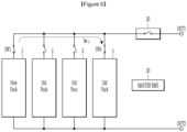
second battery pack 2 is completed (step S500 to be described below), a next target battery pack, thethird battery pack 3, and a new battery, thefirst battery pack 1, may be connected in parallel. Referring toFIG. 4 , themaster BMS 30 may connect thefirst battery pack 1 and thethird battery pack 3 in parallel by turning on the first pack switch SW1 and the third pack switch SW3. - For another example, when the estimation of the internal resistance (DCIR) of the
third battery pack 3 is completed (step S500 to be described below), the fourth battery pack 4 as the next target battery pack and thefirst battery 1 as the new battery pack may be connected in parallel. Referring toFIG. 5 , themaster BMS 30 may connect thefirst battery pack 1 and the fourth battery pack 4 in parallel by turning on the first pack switch SW1 and the fourth pack switch SW4. - Next, the
master BMS 30 receives a pack current value and a pack voltage value from each of the new battery pack and the target battery pack (S400). - Referring to
FIG. 3 , themaster BMS 30 receives a first pack current I1 value and a first pack voltage V1 value from thefirst battery pack 1. In addition, themaster BMS 30 receives the second pack current I2 value and the second pack voltage V2 value from thesecond battery pack 2. At this time, the first pack current I1 is a first compensation current Im flowing between thefirst battery pack 1 and thesecond battery pack 2 connected in parallel. Also, the second pack current I2 is the first compensation current Im flowing between thefirst battery pack 1 and thesecond battery pack 2 connected in parallel. That is, when the first compensation current Im is measured in thefirst battery pack 1, the first compensation current Im may be the first pack current I1, and when the first pack current I1 is measured in thesecond battery pack 2, the first pack current I1 may be the second pack current I2. - Also, the first pack voltage V1 and the second pack voltage V2 may be pack voltages measured before the
first battery pack 1 and thesecond battery pack 2 are connected in parallel. When thefirst battery pack 1 and thesecond battery pack 2 are connected in parallel, the first compensation current Im flows due to a first pack voltage difference ΔVs. Then, due to the self-balancing effect, the voltage values of the respective pack voltages of thefirst battery pack 1 and thesecond battery pack 2 may be the same. - Next, the
master BMS 30 estimates a resistance value of the target resistance (Rold_t), which is the internal resistance (DCIR) of the target battery pack, based on the current value of the first compensation current Im, the current value of the second compensation current Idiff, the resistance value of the new resistor Rnew, the resistance value of the first reference resistor Rref_1, and the resistance value of the second reference resistance Rref_2 (S500). - A compensation current is a current generated by a voltage difference between battery packs, and is a current flowing to match voltage values between battery packs connected in parallel. According to an example embodiment, the first compensation current Im is a compensation current flowing between a new battery pack and a target battery pack connected in parallel. The second compensation current Idiff is a compensation current flowing between the first and second reference battery packs having a second pack voltage difference value ΔVd that is the same voltage value as the first pack voltage difference value ΔVs between the new battery pack and the target battery pack.
- In operation S500, first, the
master BMS 30 calculates the first pack voltage difference value (ΔVs=|V1-V2|). For example, inFIG. 3 , themaster BMS 30 may calculate the first pack voltage difference value ΔVs that is a difference value between the first pack voltage V1 of thefirst battery pack 1 and the second pack voltage V2 of thesecond battery pack 2. At this time, it is assumed that the first pack voltage difference value ΔVs is 20V. - In step S500, the
master BMS 30 may extract the current value (e.g., 5A) of the second compensation current Idiff corresponding to the second pack voltage difference value (ΔVd = 20V), which is the same voltage value as the first pack voltage difference value (ΔVs = 20V), the resistance value (2Ω) of the first reference resistance Rref_1, and the resistance value (2Ω) of the second reference resistance Rref_2 from the look-up table. - The first pack voltage difference value ΔVs may be a difference value between pack voltages of the new battery pack and the target battery pack. The second pack voltage difference ΔVd may be a difference value between pack voltages of the first standard battery pack and the second standard battery pack.
- Table 1 below shows the look-up table in which the current value of the second compensation current Idiff, corresponding to the difference value ΔVd of the second pack voltage, the resistance values of the first reference resistor Rref_1, and the second reference resistor Rref_2 are mapped and recorded.
(Table 1) Second pack voltage difference value (ΔVd) Second compensation current (Idiff) First reference resistance (Rref_1) Second reference resistance (Rref_2) 1V 1a Ra1 Ra2 2V 1b Rb1 Rb2 3V 1c Rc1 Rc2 ... ... ... ... 20V 5A 2 Ω 2 Ω ... ... ... ... - In step S500, the
master BMS 30 may calculate or estimate the resistance value of the target resistance (Rold_t) by putting the current value of the first compensation current Im, the current value of the second compensation current Idiff, the resistance value of the new resistor Rnew, the resistance value of the first reference resistor Rref_1, and the resistance value of the second reference resistance Rref_2 into Equation (1) below:
- Specifically, Equation (1) may be derived on the premise that Equation (2) and Equation (3) are the same. That is, Equation (2) below is an equation for the first pack voltage difference value (ΔVs = 20V), and Equation (3) below is an equation for the second pack voltage difference value (ΔVd = 20V).

- In Equation (2), the first pack voltage difference ΔVs represents the product of the first compensation current Im and the combined internal resistance Rold_t + Rnew of the battery packs connected in parallel. In this case, the current value of the first compensation current Im may be a current value measured in the battery pack, and the resistance value of the new resistor Rnew may be a known resistance value.

- In Equation (3), the second pack voltage difference value ΔVd represents the product of the second compensation current Idiff and the combined internal resistance (Rref_1 + Rref_2) of the battery packs connected in parallel. At this time, the current value of the second compensation current (Id), the resistance value of the first reference resistor Rref_1, and the resistance value of the second reference resistor Rref_2 are values that may be known through the look-up table.
- In addition, in the above equation, when the performance of the new battery pack, the first reference battery pack, and the second reference battery pack are the same, and it is an unused new battery pack, the internal resistance (DCIR) value of each battery pack may be the same. In this case, Equation (1) above may be expressed as E equation (4) below.
- For example, it is assumed that the current value of the first compensation current Im is 2A, the current value of the second compensation current Idiff is 5A, and a resistance value of each of the new resistance Rnew, the first reference resistance Rref_1, and the second reference resistance Rref_2 is 2Ω. Then, the
master BMS 30 may estimate the resistance value of the target resistance Rold_t as 8 Ω. - Next, the
master BMS 30 determines whether there is an old battery pack whose internal resistance value needs to be estimated (S600). - Next, when there is an old battery pack for which estimation of an internal resistance value is required, as a result of the determination (S600, Yes), the process repeats again from S200 described above. For example, when the
second battery pack 2 is selected as the target battery pack and the estimation of the resistance value of the internal resistance (DCIR) of thesecond battery pack 2 is completed, themaster BMS 30 may select thethird battery pack 3 as a target battery pack. In addition, when the estimation of the resistance value of the internal resistance (DCIR) of thethird battery pack 3 is completed, themaster BMS 30 may select the fourth battery pack 4 as a target battery pack. - Next, when there is no old battery pack for which estimation of an internal resistance value is required, as a result of the determination (S600, No), the
master BMS 30 terminates the estimation logic of the internal resistance value. - The example embodiments of the present invention have been described in detail. However, the scope of the present invention is not limited thereto and it will be apparent to those skilled in the art that modifications and variations may be made without departing from the spirit and scope of the invention.
Claims (12)
- A battery system comprising:a battery including a new battery pack having a known internal resistance value and a target battery pack having an internal resistance value to be estimated, anda master battery management system (BMS) configured to estimate a target resistance value of the target battery pack based on at least one of:a current value of a first compensation current flowing from the new battery pack to the target battery pack when the new battery pack and the target battery pack are connected in parallel,a new resistance value of the new battery pack,a current value of a second compensation current corresponding to a first pack voltage difference value of the new battery pack and the target battery pack,a first reference resistance value, anda second reference resistance value.
- The battery system of claim 1, wherein:the second compensation current is a compensation current flowing when a first reference battery pack and a second reference battery pack having a second pack voltage difference value equal to the first pack voltage difference value are connected in parallel,the first reference resistance value is a value of an internal resistance of the first reference battery pack, andthe second reference resistance value is a value of an internal resistance of the second reference battery pack.
- The battery system of claim 2, further comprising:
a memory configured to store a look-up table having mapped and recorded therein:a current value of the second compensation current corresponding to each of a plurality of second pack voltage difference values including the second pack voltage difference value, andthe first reference resistance value and the second reference resistance value. - The battery system of claim 3, wherein:the master BMS,selects a second pack voltage difference value having a same voltage value as that of the first pack voltage difference value from among the plurality of second pack voltage difference values, andestimates the target resistance value of the target battery pack by extracting the current value of the second compensation current mapped to the second pack voltage difference value, the first reference resistance value, and the second reference resistance value.
- The battery system of claim 2, wherein:the master BMS,estimates the target resistance value (Rold_t) based on the current value of the first compensation current (Im), the new resistance value (Rnew), the current value of the second compensation current (Id), the first reference resistance (Rref_1) value, and the second reference resistance (Rref_2) put into Equation (1) below:

- The battery system of claim 1, wherein:
each of the new battery pack and the target battery pack includes:a battery module including a plurality of battery cells, a voltage sensor configured to measure a pack voltage, which is a voltage across the battery module, and a current sensor configured to measure a pack current flowing in the battery module; anda pack switch connecting the battery module to the battery system in parallel through an ON operation, and a slave BMS configured to transmit measurement results from the voltage sensor and the current sensor by communicating with the master BMS and receive a control signal for controlling a switching operation of the pack switch. - The battery system of claim 6, wherein:the master BMS,receives a first pack voltage value of the new battery pack and a second pack voltage value of the target battery pack measured before the new battery pack and the target battery pack are connected in parallel, and the current value of the first compensation current measured after the new battery pack and the target battery pack are connected in parallel, andcalculates the first pack voltage difference value, which is a difference value between the first pack voltage value and the second pack voltage value.
- A method for estimating a battery resistance to estimate an internal resistance value of a target battery pack in a battery system including a new battery pack having a known internal resistance value and a plurality of old battery packs having internal resistance values to be estimated, the method comprising:selecting the target battery pack from among the plurality of old battery packs according to a predetermined criterion;connecting the new battery pack and the target battery pack in parallel;receiving a current value of a first compensation current flowing between the new battery pack and the target battery pack connected in parallel, a first pack voltage value of the new battery pack, and a second pack voltage value of the target battery pack; andestimating a target resistance value of the target battery pack based on at least one of:a current value of the first compensation current,a new resistance value of the new battery pack,a current value of a second compensation current corresponding to a first pack voltage difference value between the new battery pack and the target battery pack,a first reference resistance value, anda second reference resistance value.
- The method of claim 8, wherein:the second compensation current is a compensation current flowing when a first reference battery pack and a second reference battery pack having a second pack voltage difference value equal to the first pack voltage difference value are connected in parallel,the first reference resistance value is a value of an internal resistance of the first reference battery pack, andthe second reference resistance value is a value an internal resistance of the second reference battery pack.
- The method of claim 9, wherein:
the estimating of the target resistance value of the target battery pack includes:calculating the first pack voltage difference value, which is a difference value between the first pack voltage value and the second pack voltage value; andextracting the current value of the second compensation current corresponding to the second pack voltage difference value, which is a same voltage value as the first pack voltage difference value, the first reference resistance value, and the second reference resistance value, from a look-up table. - The method of claim 10, wherein:in the estimating of the target resistance value of the target battery pack,after the extracting from the lookup table,the target resistance value (Rold_t) is estimated based on the current value of the first compensation current (Im), the new resistance value (Rnew), the current value of the second compensation current (Id), the first reference resistance (Rref_1) value, and the second reference resistance (Rref_2) put into Equation (1) below:

- The method of claim 8, wherein:
the receiving of the current value of the first compensation current includes:
receiving the first pack voltage value of the new battery pack and the second pack voltage value of the target battery pack measured before the new battery pack and the target battery pack are connected in parallel, and the current value of the first compensation current measured after the new battery pack and the target battery pack are connected in parallel.
Applications Claiming Priority (2)
| Application Number | Priority Date | Filing Date | Title |
|---|---|---|---|
| KR1020210155537A KR102929046B1 (en) | 2021-11-12 | 2021-11-12 | Method for estimating dcir of battery and battery system providing the same |
| PCT/KR2022/017453 WO2023085730A1 (en) | 2021-11-12 | 2022-11-08 | Method for estimating dcir of battery and battery system providing same |
Publications (3)
| Publication Number | Publication Date |
|---|---|
| EP4382938A1 true EP4382938A1 (en) | 2024-06-12 |
| EP4382938A4 EP4382938A4 (en) | 2024-12-04 |
| EP4382938B1 EP4382938B1 (en) | 2025-12-31 |
Family
ID=86336072
Family Applications (1)
| Application Number | Title | Priority Date | Filing Date |
|---|---|---|---|
| EP22893150.7A Active EP4382938B1 (en) | 2021-11-12 | 2022-11-08 | METHOD FOR ESTIMATING THE DCIR OF A BATTERY AND BATTERY SYSTEM WITH IT |
Country Status (7)
| Country | Link |
|---|---|
| US (1) | US20240377466A1 (en) |
| EP (1) | EP4382938B1 (en) |
| JP (1) | JP7661613B2 (en) |
| KR (1) | KR102929046B1 (en) |
| CN (1) | CN117957454A (en) |
| ES (1) | ES3059148T3 (en) |
| WO (1) | WO2023085730A1 (en) |
Family Cites Families (14)
| Publication number | Priority date | Publication date | Assignee | Title |
|---|---|---|---|---|
| JP4542536B2 (en) | 2006-11-06 | 2010-09-15 | 株式会社日立製作所 | Power control device |
| JP2012167978A (en) | 2011-02-14 | 2012-09-06 | Railway Technical Research Institute | Internal resistance estimation method, battery degradation determination method, and control apparatus |
| JP2013096785A (en) | 2011-10-31 | 2013-05-20 | Panasonic Corp | Battery deterioration determination device and battery deterioration determination method |
| KR101741183B1 (en) * | 2011-11-24 | 2017-05-30 | 에스케이이노베이션 주식회사 | Apparatus and Method for Estimating the Battery Internal Resistance |
| JP5733275B2 (en) * | 2012-07-13 | 2015-06-10 | トヨタ自動車株式会社 | Battery pack control device and battery pack reuse determination method |
| JP6201763B2 (en) * | 2013-01-22 | 2017-09-27 | 株式会社Gsユアサ | Storage unit connection information acquisition device |
| JP6323639B2 (en) | 2013-06-12 | 2018-05-16 | 三菱自動車工業株式会社 | Abnormality judgment device for battery pack |
| JP6364396B2 (en) * | 2015-10-27 | 2018-07-25 | 本田技研工業株式会社 | Power storage device, transport device and control method |
| US20190305263A1 (en) * | 2016-09-21 | 2019-10-03 | Automotive Energy Supply Corporation | Battery System |
| WO2019188890A1 (en) * | 2018-03-28 | 2019-10-03 | 古河電気工業株式会社 | Electricity storage system and measurement method |
| JP6853805B2 (en) * | 2018-09-13 | 2021-03-31 | 株式会社Subaru | Electric vehicle |
| CN109802189B (en) * | 2019-03-26 | 2024-11-15 | 河南许继仪表有限公司 | Capacity expansion system and capacity expansion method of lithium iron phosphate battery pack |
| JP7129960B2 (en) | 2019-09-11 | 2022-09-02 | 株式会社日立製作所 | Battery monitor and battery system |
| KR20210155537A (en) | 2020-06-16 | 2021-12-23 | 정진혁 | Package pack for fishing paste bait and method for manufacturing fishing paste bait using the same |
-
2021
- 2021-11-12 KR KR1020210155537A patent/KR102929046B1/en active Active
-
2022
- 2022-11-08 CN CN202280060434.3A patent/CN117957454A/en active Pending
- 2022-11-08 JP JP2024507921A patent/JP7661613B2/en active Active
- 2022-11-08 EP EP22893150.7A patent/EP4382938B1/en active Active
- 2022-11-08 US US18/688,294 patent/US20240377466A1/en active Pending
- 2022-11-08 ES ES22893150T patent/ES3059148T3/en active Active
- 2022-11-08 WO PCT/KR2022/017453 patent/WO2023085730A1/en not_active Ceased
Also Published As
| Publication number | Publication date |
|---|---|
| KR102929046B1 (en) | 2026-02-19 |
| EP4382938B1 (en) | 2025-12-31 |
| JP2024532739A (en) | 2024-09-10 |
| JP7661613B2 (en) | 2025-04-14 |
| ES3059148T3 (en) | 2026-03-19 |
| CN117957454A (en) | 2024-04-30 |
| EP4382938A4 (en) | 2024-12-04 |
| KR20230069473A (en) | 2023-05-19 |
| WO2023085730A1 (en) | 2023-05-19 |
| US20240377466A1 (en) | 2024-11-14 |
Similar Documents
| Publication | Publication Date | Title |
|---|---|---|
| EP1801947B1 (en) | Method for compensating state of charge of battery and battery management system using the same | |
| US10873201B2 (en) | Battery management apparatus and method for protecting a lithium iron phosphate cell from over-voltage using the same | |
| US8134338B2 (en) | Battery management system and driving method thereof | |
| EP1801604B1 (en) | Method for compensating state of charge of battery and battery management system using the same | |
| JP7041800B2 (en) | Battery capacity estimation device and method, battery management device and method equipped with this | |
| EP3518382B1 (en) | Power supply system | |
| EP1801605B1 (en) | Method for compensating state of charge of a battery and battery management system using the same | |
| US9366728B2 (en) | Degradation measurement device, secondary battery pack, degradation measurement method, and program | |
| CN101765941A (en) | Battery internal short circuit detection device, method, battery pack, and electronic device system | |
| KR20180079771A (en) | Battery management apparatus and soc calibrating method using the same | |
| KR20130049460A (en) | Battery pack, battery protection circuit, and battery system | |
| KR20140084320A (en) | Method and system managing the electroic charges of battery cells | |
| US8829854B2 (en) | Secondary battery | |
| EP3831646A2 (en) | Battery management method, battery device, vehicle comprising battery | |
| US20110050204A1 (en) | Secondary battery | |
| US11598819B2 (en) | Method for ascertaining a charge state of a battery system, battery system | |
| CN113785464B (en) | Device and method for controlling power of a parallel multi-group system | |
| EP4382938A1 (en) | Method for estimating dcir of battery and battery system providing same | |
| KR102902823B1 (en) | Cell voltage estimation method and battery system providing the same | |
| KR20230036468A (en) | Battery balancing method and battery system providing the same |
Legal Events
| Date | Code | Title | Description |
|---|---|---|---|
| STAA | Information on the status of an ep patent application or granted ep patent |
Free format text: STATUS: THE INTERNATIONAL PUBLICATION HAS BEEN MADE |
|
| PUAI | Public reference made under article 153(3) epc to a published international application that has entered the european phase |
Free format text: ORIGINAL CODE: 0009012 |
|
| STAA | Information on the status of an ep patent application or granted ep patent |
Free format text: STATUS: REQUEST FOR EXAMINATION WAS MADE |
|
| 17P | Request for examination filed |
Effective date: 20240304 |
|
| AK | Designated contracting states |
Kind code of ref document: A1 Designated state(s): AL AT BE BG CH CY CZ DE DK EE ES FI FR GB GR HR HU IE IS IT LI LT LU LV MC ME MK MT NL NO PL PT RO RS SE SI SK SM TR |
|
| A4 | Supplementary search report drawn up and despatched |
Effective date: 20241105 |
|
| RIC1 | Information provided on ipc code assigned before grant |
Ipc: G01R 31/392 20190101ALI20241029BHEP Ipc: G01R 31/396 20190101ALI20241029BHEP Ipc: G01R 19/00 20060101ALI20241029BHEP Ipc: G01R 19/10 20060101ALI20241029BHEP Ipc: G01R 31/3842 20190101ALI20241029BHEP Ipc: G01R 31/367 20190101ALI20241029BHEP Ipc: G01R 31/389 20190101AFI20241029BHEP |
|
| DAV | Request for validation of the european patent (deleted) | ||
| DAX | Request for extension of the european patent (deleted) | ||
| GRAP | Despatch of communication of intention to grant a patent |
Free format text: ORIGINAL CODE: EPIDOSNIGR1 |
|
| STAA | Information on the status of an ep patent application or granted ep patent |
Free format text: STATUS: GRANT OF PATENT IS INTENDED |
|
| INTG | Intention to grant announced |
Effective date: 20250630 |
|
| P01 | Opt-out of the competence of the unified patent court (upc) registered |
Free format text: CASE NUMBER: APP_31605/2025 Effective date: 20250701 |
|
| GRAS | Grant fee paid |
Free format text: ORIGINAL CODE: EPIDOSNIGR3 |
|
| GRAA | (expected) grant |
Free format text: ORIGINAL CODE: 0009210 |
|
| STAA | Information on the status of an ep patent application or granted ep patent |
Free format text: STATUS: THE PATENT HAS BEEN GRANTED |
|
| AK | Designated contracting states |
Kind code of ref document: B1 Designated state(s): AL AT BE BG CH CY CZ DE DK EE ES FI FR GB GR HR HU IE IS IT LI LT LU LV MC ME MK MT NL NO PL PT RO RS SE SI SK SM TR |
|
| REG | Reference to a national code |
Ref country code: CH Ref legal event code: F10 Free format text: ST27 STATUS EVENT CODE: U-0-0-F10-F00 (AS PROVIDED BY THE NATIONAL OFFICE) Effective date: 20251231 Ref country code: GB Ref legal event code: FG4D |
|
| REG | Reference to a national code |
Ref country code: DE Ref legal event code: R096 Ref document number: 602022028165 Country of ref document: DE |
|
| REG | Reference to a national code |
Ref country code: IE Ref legal event code: FG4D |
|
| REG | Reference to a national code |
Ref country code: ES Ref legal event code: FG2A Ref document number: 3059148 Country of ref document: ES Kind code of ref document: T3 Effective date: 20260319 |
|
| REG | Reference to a national code |
Ref country code: LT Ref legal event code: MG9D |
|
| PG25 | Lapsed in a contracting state [announced via postgrant information from national office to epo] |
Ref country code: NO Free format text: LAPSE BECAUSE OF FAILURE TO SUBMIT A TRANSLATION OF THE DESCRIPTION OR TO PAY THE FEE WITHIN THE PRESCRIBED TIME-LIMIT Effective date: 20260331 |
|
| PG25 | Lapsed in a contracting state [announced via postgrant information from national office to epo] |
Ref country code: FI Free format text: LAPSE BECAUSE OF FAILURE TO SUBMIT A TRANSLATION OF THE DESCRIPTION OR TO PAY THE FEE WITHIN THE PRESCRIBED TIME-LIMIT Effective date: 20251231 Ref country code: HR Free format text: LAPSE BECAUSE OF FAILURE TO SUBMIT A TRANSLATION OF THE DESCRIPTION OR TO PAY THE FEE WITHIN THE PRESCRIBED TIME-LIMIT Effective date: 20251231 |
|
| PG25 | Lapsed in a contracting state [announced via postgrant information from national office to epo] |
Ref country code: RS Free format text: LAPSE BECAUSE OF FAILURE TO SUBMIT A TRANSLATION OF THE DESCRIPTION OR TO PAY THE FEE WITHIN THE PRESCRIBED TIME-LIMIT Effective date: 20260331 |