US11999257B2 - Battery management method, battery device, and vehicle comprising battery device - Google Patents
Battery management method, battery device, and vehicle comprising battery device Download PDFInfo
- Publication number
- US11999257B2 US11999257B2 US17/276,716 US202017276716A US11999257B2 US 11999257 B2 US11999257 B2 US 11999257B2 US 202017276716 A US202017276716 A US 202017276716A US 11999257 B2 US11999257 B2 US 11999257B2
- Authority
- US
- United States
- Prior art keywords
- soc
- battery
- battery pack
- setting range
- information
- Prior art date
- Legal status (The legal status is an assumption and is not a legal conclusion. Google has not performed a legal analysis and makes no representation as to the accuracy of the status listed.)
- Active, expires
Links
- 238000007726 management method Methods 0.000 title claims description 26
- 230000015556 catabolic process Effects 0.000 claims abstract description 8
- 238000006731 degradation reaction Methods 0.000 claims abstract description 8
- 238000012544 monitoring process Methods 0.000 claims abstract description 7
- 238000000034 method Methods 0.000 claims description 29
- 238000006243 chemical reaction Methods 0.000 claims description 6
- 238000007599 discharging Methods 0.000 description 23
- 230000006866 deterioration Effects 0.000 description 5
- 238000004364 calculation method Methods 0.000 description 3
- 230000002159 abnormal effect Effects 0.000 description 2
- 230000008901 benefit Effects 0.000 description 2
- 238000010586 diagram Methods 0.000 description 2
- 230000001681 protective effect Effects 0.000 description 2
- 238000007619 statistical method Methods 0.000 description 2
- HBBGRARXTFLTSG-UHFFFAOYSA-N Lithium ion Chemical compound [Li+] HBBGRARXTFLTSG-UHFFFAOYSA-N 0.000 description 1
- 230000002950 deficient Effects 0.000 description 1
- 230000000694 effects Effects 0.000 description 1
- 239000003792 electrolyte Substances 0.000 description 1
- 230000002687 intercalation Effects 0.000 description 1
- 238000009830 intercalation Methods 0.000 description 1
- 229910001416 lithium ion Inorganic materials 0.000 description 1
- 238000012986 modification Methods 0.000 description 1
- 230000004048 modification Effects 0.000 description 1
- 239000012071 phase Substances 0.000 description 1
- 239000007790 solid phase Substances 0.000 description 1
- 239000000126 substance Substances 0.000 description 1
- 230000002123 temporal effect Effects 0.000 description 1
Images


Classifications
-
- B—PERFORMING OPERATIONS; TRANSPORTING
- B60—VEHICLES IN GENERAL
- B60L—PROPULSION OF ELECTRICALLY-PROPELLED VEHICLES; SUPPLYING ELECTRIC POWER FOR AUXILIARY EQUIPMENT OF ELECTRICALLY-PROPELLED VEHICLES; ELECTRODYNAMIC BRAKE SYSTEMS FOR VEHICLES IN GENERAL; MAGNETIC SUSPENSION OR LEVITATION FOR VEHICLES; MONITORING OPERATING VARIABLES OF ELECTRICALLY-PROPELLED VEHICLES; ELECTRIC SAFETY DEVICES FOR ELECTRICALLY-PROPELLED VEHICLES
- B60L58/00—Methods or circuit arrangements for monitoring or controlling batteries or fuel cells, specially adapted for electric vehicles
- B60L58/10—Methods or circuit arrangements for monitoring or controlling batteries or fuel cells, specially adapted for electric vehicles for monitoring or controlling batteries
- B60L58/12—Methods or circuit arrangements for monitoring or controlling batteries or fuel cells, specially adapted for electric vehicles for monitoring or controlling batteries responding to state of charge [SoC]
- B60L58/13—Maintaining the SoC within a determined range
-
- B—PERFORMING OPERATIONS; TRANSPORTING
- B60—VEHICLES IN GENERAL
- B60K—ARRANGEMENT OR MOUNTING OF PROPULSION UNITS OR OF TRANSMISSIONS IN VEHICLES; ARRANGEMENT OR MOUNTING OF PLURAL DIVERSE PRIME-MOVERS IN VEHICLES; AUXILIARY DRIVES FOR VEHICLES; INSTRUMENTATION OR DASHBOARDS FOR VEHICLES; ARRANGEMENTS IN CONNECTION WITH COOLING, AIR INTAKE, GAS EXHAUST OR FUEL SUPPLY OF PROPULSION UNITS IN VEHICLES
- B60K1/00—Arrangement or mounting of electrical propulsion units
- B60K1/04—Arrangement or mounting of electrical propulsion units of the electric storage means for propulsion
-
- B—PERFORMING OPERATIONS; TRANSPORTING
- B60—VEHICLES IN GENERAL
- B60L—PROPULSION OF ELECTRICALLY-PROPELLED VEHICLES; SUPPLYING ELECTRIC POWER FOR AUXILIARY EQUIPMENT OF ELECTRICALLY-PROPELLED VEHICLES; ELECTRODYNAMIC BRAKE SYSTEMS FOR VEHICLES IN GENERAL; MAGNETIC SUSPENSION OR LEVITATION FOR VEHICLES; MONITORING OPERATING VARIABLES OF ELECTRICALLY-PROPELLED VEHICLES; ELECTRIC SAFETY DEVICES FOR ELECTRICALLY-PROPELLED VEHICLES
- B60L3/00—Electric devices on electrically-propelled vehicles for safety purposes; Monitoring operating variables, e.g. speed, deceleration or energy consumption
- B60L3/0023—Detecting, eliminating, remedying or compensating for drive train abnormalities, e.g. failures within the drive train
- B60L3/0046—Detecting, eliminating, remedying or compensating for drive train abnormalities, e.g. failures within the drive train relating to electric energy storage systems, e.g. batteries or capacitors
-
- B—PERFORMING OPERATIONS; TRANSPORTING
- B60—VEHICLES IN GENERAL
- B60L—PROPULSION OF ELECTRICALLY-PROPELLED VEHICLES; SUPPLYING ELECTRIC POWER FOR AUXILIARY EQUIPMENT OF ELECTRICALLY-PROPELLED VEHICLES; ELECTRODYNAMIC BRAKE SYSTEMS FOR VEHICLES IN GENERAL; MAGNETIC SUSPENSION OR LEVITATION FOR VEHICLES; MONITORING OPERATING VARIABLES OF ELECTRICALLY-PROPELLED VEHICLES; ELECTRIC SAFETY DEVICES FOR ELECTRICALLY-PROPELLED VEHICLES
- B60L58/00—Methods or circuit arrangements for monitoring or controlling batteries or fuel cells, specially adapted for electric vehicles
- B60L58/10—Methods or circuit arrangements for monitoring or controlling batteries or fuel cells, specially adapted for electric vehicles for monitoring or controlling batteries
- B60L58/12—Methods or circuit arrangements for monitoring or controlling batteries or fuel cells, specially adapted for electric vehicles for monitoring or controlling batteries responding to state of charge [SoC]
-
- B—PERFORMING OPERATIONS; TRANSPORTING
- B60—VEHICLES IN GENERAL
- B60L—PROPULSION OF ELECTRICALLY-PROPELLED VEHICLES; SUPPLYING ELECTRIC POWER FOR AUXILIARY EQUIPMENT OF ELECTRICALLY-PROPELLED VEHICLES; ELECTRODYNAMIC BRAKE SYSTEMS FOR VEHICLES IN GENERAL; MAGNETIC SUSPENSION OR LEVITATION FOR VEHICLES; MONITORING OPERATING VARIABLES OF ELECTRICALLY-PROPELLED VEHICLES; ELECTRIC SAFETY DEVICES FOR ELECTRICALLY-PROPELLED VEHICLES
- B60L58/00—Methods or circuit arrangements for monitoring or controlling batteries or fuel cells, specially adapted for electric vehicles
- B60L58/10—Methods or circuit arrangements for monitoring or controlling batteries or fuel cells, specially adapted for electric vehicles for monitoring or controlling batteries
- B60L58/16—Methods or circuit arrangements for monitoring or controlling batteries or fuel cells, specially adapted for electric vehicles for monitoring or controlling batteries responding to battery ageing, e.g. to the number of charging cycles or the state of health [SoH]
-
- B—PERFORMING OPERATIONS; TRANSPORTING
- B60—VEHICLES IN GENERAL
- B60L—PROPULSION OF ELECTRICALLY-PROPELLED VEHICLES; SUPPLYING ELECTRIC POWER FOR AUXILIARY EQUIPMENT OF ELECTRICALLY-PROPELLED VEHICLES; ELECTRODYNAMIC BRAKE SYSTEMS FOR VEHICLES IN GENERAL; MAGNETIC SUSPENSION OR LEVITATION FOR VEHICLES; MONITORING OPERATING VARIABLES OF ELECTRICALLY-PROPELLED VEHICLES; ELECTRIC SAFETY DEVICES FOR ELECTRICALLY-PROPELLED VEHICLES
- B60L58/00—Methods or circuit arrangements for monitoring or controlling batteries or fuel cells, specially adapted for electric vehicles
- B60L58/10—Methods or circuit arrangements for monitoring or controlling batteries or fuel cells, specially adapted for electric vehicles for monitoring or controlling batteries
- B60L58/18—Methods or circuit arrangements for monitoring or controlling batteries or fuel cells, specially adapted for electric vehicles for monitoring or controlling batteries of two or more battery modules
- B60L58/21—Methods or circuit arrangements for monitoring or controlling batteries or fuel cells, specially adapted for electric vehicles for monitoring or controlling batteries of two or more battery modules having the same nominal voltage
-
- G—PHYSICS
- G01—MEASURING; TESTING
- G01R—MEASURING ELECTRIC VARIABLES; MEASURING MAGNETIC VARIABLES
- G01R31/00—Arrangements for testing electric properties; Arrangements for locating electric faults; Arrangements for electrical testing characterised by what is being tested not provided for elsewhere
- G01R31/36—Arrangements for testing, measuring or monitoring the electrical condition of accumulators or electric batteries, e.g. capacity or state of charge [SoC]
- G01R31/382—Arrangements for monitoring battery or accumulator variables, e.g. SoC
- G01R31/3842—Arrangements for monitoring battery or accumulator variables, e.g. SoC combining voltage and current measurements
-
- G—PHYSICS
- G01—MEASURING; TESTING
- G01R—MEASURING ELECTRIC VARIABLES; MEASURING MAGNETIC VARIABLES
- G01R31/00—Arrangements for testing electric properties; Arrangements for locating electric faults; Arrangements for electrical testing characterised by what is being tested not provided for elsewhere
- G01R31/36—Arrangements for testing, measuring or monitoring the electrical condition of accumulators or electric batteries, e.g. capacity or state of charge [SoC]
- G01R31/392—Determining battery ageing or deterioration, e.g. state of health
-
- G—PHYSICS
- G01—MEASURING; TESTING
- G01R—MEASURING ELECTRIC VARIABLES; MEASURING MAGNETIC VARIABLES
- G01R31/00—Arrangements for testing electric properties; Arrangements for locating electric faults; Arrangements for electrical testing characterised by what is being tested not provided for elsewhere
- G01R31/36—Arrangements for testing, measuring or monitoring the electrical condition of accumulators or electric batteries, e.g. capacity or state of charge [SoC]
- G01R31/396—Acquisition or processing of data for testing or for monitoring individual cells or groups of cells within a battery
-
- H—ELECTRICITY
- H01—ELECTRIC ELEMENTS
- H01M—PROCESSES OR MEANS, e.g. BATTERIES, FOR THE DIRECT CONVERSION OF CHEMICAL ENERGY INTO ELECTRICAL ENERGY
- H01M10/00—Secondary cells; Manufacture thereof
- H01M10/42—Methods or arrangements for servicing or maintenance of secondary cells or secondary half-cells
- H01M10/425—Structural combination with electronic components, e.g. electronic circuits integrated to the outside of the casing
-
- B—PERFORMING OPERATIONS; TRANSPORTING
- B60—VEHICLES IN GENERAL
- B60L—PROPULSION OF ELECTRICALLY-PROPELLED VEHICLES; SUPPLYING ELECTRIC POWER FOR AUXILIARY EQUIPMENT OF ELECTRICALLY-PROPELLED VEHICLES; ELECTRODYNAMIC BRAKE SYSTEMS FOR VEHICLES IN GENERAL; MAGNETIC SUSPENSION OR LEVITATION FOR VEHICLES; MONITORING OPERATING VARIABLES OF ELECTRICALLY-PROPELLED VEHICLES; ELECTRIC SAFETY DEVICES FOR ELECTRICALLY-PROPELLED VEHICLES
- B60L2240/00—Control parameters of input or output; Target parameters
- B60L2240/40—Drive Train control parameters
- B60L2240/54—Drive Train control parameters related to batteries
- B60L2240/547—Voltage
-
- B—PERFORMING OPERATIONS; TRANSPORTING
- B60—VEHICLES IN GENERAL
- B60L—PROPULSION OF ELECTRICALLY-PROPELLED VEHICLES; SUPPLYING ELECTRIC POWER FOR AUXILIARY EQUIPMENT OF ELECTRICALLY-PROPELLED VEHICLES; ELECTRODYNAMIC BRAKE SYSTEMS FOR VEHICLES IN GENERAL; MAGNETIC SUSPENSION OR LEVITATION FOR VEHICLES; MONITORING OPERATING VARIABLES OF ELECTRICALLY-PROPELLED VEHICLES; ELECTRIC SAFETY DEVICES FOR ELECTRICALLY-PROPELLED VEHICLES
- B60L2240/00—Control parameters of input or output; Target parameters
- B60L2240/40—Drive Train control parameters
- B60L2240/54—Drive Train control parameters related to batteries
- B60L2240/549—Current
-
- B—PERFORMING OPERATIONS; TRANSPORTING
- B60—VEHICLES IN GENERAL
- B60Y—INDEXING SCHEME RELATING TO ASPECTS CROSS-CUTTING VEHICLE TECHNOLOGY
- B60Y2200/00—Type of vehicle
- B60Y2200/90—Vehicles comprising electric prime movers
- B60Y2200/91—Electric vehicles
-
- H—ELECTRICITY
- H01—ELECTRIC ELEMENTS
- H01M—PROCESSES OR MEANS, e.g. BATTERIES, FOR THE DIRECT CONVERSION OF CHEMICAL ENERGY INTO ELECTRICAL ENERGY
- H01M10/00—Secondary cells; Manufacture thereof
- H01M10/42—Methods or arrangements for servicing or maintenance of secondary cells or secondary half-cells
- H01M10/425—Structural combination with electronic components, e.g. electronic circuits integrated to the outside of the casing
- H01M2010/4271—Battery management systems including electronic circuits, e.g. control of current or voltage to keep battery in healthy state, cell balancing
-
- H—ELECTRICITY
- H01—ELECTRIC ELEMENTS
- H01M—PROCESSES OR MEANS, e.g. BATTERIES, FOR THE DIRECT CONVERSION OF CHEMICAL ENERGY INTO ELECTRICAL ENERGY
- H01M10/00—Secondary cells; Manufacture thereof
- H01M10/42—Methods or arrangements for servicing or maintenance of secondary cells or secondary half-cells
- H01M10/425—Structural combination with electronic components, e.g. electronic circuits integrated to the outside of the casing
- H01M2010/4278—Systems for data transfer from batteries, e.g. transfer of battery parameters to a controller, data transferred between battery controller and main controller
-
- Y—GENERAL TAGGING OF NEW TECHNOLOGICAL DEVELOPMENTS; GENERAL TAGGING OF CROSS-SECTIONAL TECHNOLOGIES SPANNING OVER SEVERAL SECTIONS OF THE IPC; TECHNICAL SUBJECTS COVERED BY FORMER USPC CROSS-REFERENCE ART COLLECTIONS [XRACs] AND DIGESTS
- Y02—TECHNOLOGIES OR APPLICATIONS FOR MITIGATION OR ADAPTATION AGAINST CLIMATE CHANGE
- Y02E—REDUCTION OF GREENHOUSE GAS [GHG] EMISSIONS, RELATED TO ENERGY GENERATION, TRANSMISSION OR DISTRIBUTION
- Y02E60/00—Enabling technologies; Technologies with a potential or indirect contribution to GHG emissions mitigation
- Y02E60/10—Energy storage using batteries
-
- Y—GENERAL TAGGING OF NEW TECHNOLOGICAL DEVELOPMENTS; GENERAL TAGGING OF CROSS-SECTIONAL TECHNOLOGIES SPANNING OVER SEVERAL SECTIONS OF THE IPC; TECHNICAL SUBJECTS COVERED BY FORMER USPC CROSS-REFERENCE ART COLLECTIONS [XRACs] AND DIGESTS
- Y02—TECHNOLOGIES OR APPLICATIONS FOR MITIGATION OR ADAPTATION AGAINST CLIMATE CHANGE
- Y02T—CLIMATE CHANGE MITIGATION TECHNOLOGIES RELATED TO TRANSPORTATION
- Y02T10/00—Road transport of goods or passengers
- Y02T10/60—Other road transportation technologies with climate change mitigation effect
- Y02T10/70—Energy storage systems for electromobility, e.g. batteries
Definitions
- the present disclosure relates to a battery management method, a battery device, and a vehicle including a battery.
- a battery lifespan is affected by change in energy capacity used. The larger an energy capacity change, the greater a degree of decrease of a battery lifespan.
- a battery for a vehicle is supplied with power from a plurality of battery packs, and generally, power supplied to a vehicle is controlled based on a battery pack having the most deterioration among the plurality of battery packs.
- the present invention has been made in an effort to provide a battery management method, a battery device, and a vehicle including a battery that may delay a decrease of a battery lifespan.
- An embodiment of the present invention provides a battery management method, including: receiving a SOC (state of charge) setting range; charging at least one battery pack; estimating a SOC of the at least one battery pack based on state information of the at least one battery pack; monitoring whether the estimated SOC reaches a charging reference value corresponding to an upper limit of the SOC setting range; and stopping charging when it is confirmed through a result of the monitoring that the estimated SOC reaches the charging reference value, wherein the SOC setting range may be determined based on driving information of a vehicle, and may be within a SOC limiting range, wherein the SOC limiting range is predetermined to cause a lowest degree of degradation of battery cells of the at least one battery pack.
- SOC state of charge
- the battery management method may further include deriving the SOC setting range based on the driving information.
- the battery management method may further include: monitoring whether the estimated SOC deviates from a lower limit of the SOC setting range; and when the estimated SOC deviates from the lower limit of the SOC setting range, operating the at least one battery pack in a SOC range that is lower than the SOC setting range.
- a battery device including: at least one battery pack including a plurality of battery cells connected in series; and a battery management system configured to receive a SOC setting range, estimate a SOC of the at least one battery pack based on state information of the at least one battery pack, and charge the at least one battery pack so that the estimated SOC reaches up to a charging reference value corresponding to an upper limit of the SOC setting range.
- the SOC setting range may be determined based on driving information of a vehicle, and may be within a SOC limiting range, wherein the SOC limiting range is predetermined to cause a lowest degree of degradation of battery cells of the at least one battery pack.
- the SOC setting range may be derived based on the driving information.
- a vehicle including: at least one battery pack including a plurality of battery cells connected in series; a battery management system configured to receive a SOC setting range, estimate a SOC based on state information of the at least one battery pack, and charge the at least one battery pack until the estimated SOC reaches up to a charging reference value corresponding to an upper limit of the SOC setting range; and a power converting circuit that converts power from the battery device, and supplies power to an electrical load, wherein the SOC setting range may be determined based on driving information of a vehicle, and may be within a SOC limiting range, wherein the SOC limiting range is predetermined to cause a lowest degree of degradation of battery cells of the at least one battery pack.
- the vehicle may further include an interface that receives the SOC setting range from a user.
- the SOC setting range may be derived based on the driving information.
- the battery device may be configured to monitor whether the estimated SOC deviates from a lower limit of the SOC setting range, and may be operated in a SOC range that is lower than the SOC setting range when the estimated SOC deviates from the lower limit of the SOC setting range.
- the battery device may further include: a voltage sensing control circuit configured to measure voltages at both ends of the battery pack and transmit information on the measured voltages to the battery management system; and a current measuring part configured to measure a current flowing in the battery pack and transmit information on the measured current to the battery management system, and the state information of the battery pack may include information on the measured voltages and information on the measured current.
- FIG. 1 illustrates a schematic view of a battery device according to an embodiment and a portion of a vehicle including the same.
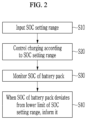
- FIG. 2 illustrates a flowchart of a battery management method according to an embodiment.
- FIG. 3 illustrates a schematic view of a charging/discharging switch device.
- FIG. 4 illustrates a block diagram of a configuration for estimating SOC by a BMS according to an embodiment.
- the present disclosure relates to a method and device for a user to set an energy use range of a battery for a vehicle and manage the battery to the set energy use range.
- a state of charge may be used as an example of an index indicating an energy use range.
- the SOC is an index indicating a state of charge of a battery, and may be displayed as a percentage remaining with respect to a full charge capacity (FCC) of the battery as a percentage.
- FCC full charge capacity
- the present invention is not limited thereto.
- an embodiment may relate to a battery management method and a battery management device that may control charging and discharging of a battery to a set energy use range, and to a vehicle including a battery management device.
- the battery may be operated within the SOC setting range in which the SOC range is limited according to driving information, and in this case, the battery may supply power to an electrical load within the SOC setting range.
- the driving information may include information such as a driving distance, a departure point, a destination, and a driving time. Specifically, a user may determine the SOC setting range according to the driving distance.
- the SOC setting range may be canceled according to a change in circumstances, such as when the driving distance is unexpectedly extended, and the battery may be operated to a SOC that is lower than a lower limit of the SOC setting range.
- the battery may be charged with a SOC that is higher than the upper limit of the SOC setting range.
- deterioration a SOC range with a small degree of reduced lifespan
- the SOC range of 30-70% is referred to as a SOC limiting range.
- the user may set it as a SOC use range when the vehicle may be operated within the SOC range of 30-70%.
- the SOC use range set as described above is an example of a SOC setting range. In this case, the SOC setting range may be within the SOC limiting range of 30-70%.
- FIG. 1 illustrates a schematic view of a battery device according to an embodiment and a portion of a vehicle including the same.
- FIG. 2 illustrates a flowchart of a battery management method according to an embodiment.
- a vehicle 1 may include a battery device 2 , a power converting circuit 4 , an electrical load 5 , an electronic control unit (ECU) 6 , and an interface 7 .
- ECU electronice control unit
- the power converting circuit 4 may convert power inputted from the battery device 2 for driving the vehicle 1 to supply power required for the electrical load 5 . Power conversion by the power converting circuit 4 may be controlled according to a signal instructing a power control operation of the ECU 6 .
- the electrical load 5 may be a motor.
- the power converting circuit 4 may convert power supplied from a charger 3 that is an external device to supply the power to the battery device 2 .
- a power conversion operation for the charging of the battery device 2 may be controlled by the ECU 6 and/or the battery device 2 .
- the power converting circuit 4 may start a battery charging operation under control of the ECU 6 , and receive a control signal for charging control from the battery device 2 during charging to supply power required for charging to the battery device 2 .
- the battery device 2 may measure a voltage of a battery pack and generate a signal for controlling charging based on the measured voltage.
- the power converting circuit 4 may be implemented as a bi-directional inverter in order to supply power to an electric load and power to a battery device.
- the power converting circuit 4 may be a DC-AC inverter when supplying power to the electrical load, and an AC-DC inverter when supplying power to the battery device.
- the ECU 6 is a circuit that controls electronic equipment of the vehicle 1 .
- the ECU 6 may transmit information about the SOC setting range to the battery device 2 .
- the interface 7 may receive a SOC setting range from a user (step S 10 in FIG. 2 ).
- the SOC setting range is upper and lower charging and discharging limits of the battery device 2 inputted from the user, and may be determined within the SOC limiting range.
- the SOC setting range is the upper and lower charging and discharging limits of the battery required for driving the distance of 100 km in 4 hours.
- the SOC limiting range for the battery is 30-70% and it is possible to be driven with a SOC of 30-60% under a corresponding condition
- the SOC setting range may be determined as a SOC of 30-60%.
- the upper charging limit may correspond to an upper limit of the SOC setting range
- the lower discharging limit may correspond to a lower limit of the SOC setting range. Accordingly, a battery pack 21 of the battery device 2 may be charged to a SOC of 60%, and discharged to a SOC of 30% after driving.
- the battery device 2 When the driving distance is a distance that cannot be driven within 30-70% of the SOC limiting range, the battery device 2 may be operated within a required SOC range in a state in which the SOC setting range is determined. That is, according to the embodiment, unlike the prior art in which deterioration of the battery cell proceeds by maintaining the SOC use range constant regardless of the driving distance, when the driving distance is a distance that may be driven within the SOC limiting range, the embodiment is an example of implementing a technical idea to maximally prevent deterioration of the battery cell by operating the battery device 2 within the SOC limiting range.
- the battery device 2 includes at least one battery pack 21 , a battery management system (BMS) 22 , a charging/discharging switch device 23 , a voltage sensing control circuit 24 , a current measuring part 25 , and a temperature sensor 26 .
- BMS battery management system
- the battery pack 21 includes a plurality of battery cells connected in series. Although only one battery pack 21 is illustrated in FIG. 1 , a plurality of battery packs may be connected in series or in parallel to supply necessary power.
- the BMS 22 may receive the SOC setting range, estimate a SOC of the battery pack 21 , and control charging and discharging of the battery pack 21 based on the estimated SOC.
- the BMS 22 controls a switching operation of the charging/discharging switch device 23 to control charging and discharging according to the SOC setting range.
- FIG. 3 illustrates a schematic view of a charging/discharging switch device.
- the charging/discharging switch device 23 includes a charging switch 231 and a discharging switch 233 , a body diode 232 is disposed between a source and a drain of the charging switch 231 , and a body diode 234 is disposed between a source and a drain of the discharging switch 233 .
- the charging switch 231 and the discharging switch 233 are configured of (e.g., comprise) n-channel transistors.
- the BMS 22 applies an on-level (high-level) gate signal VG 1 to the gate of the charging switch 231 , and an off-level (low-level) gate signal VG 2 to the gate of the discharging switch 233 .
- the BMS 22 applies the off-level (low-level) gate signal VG 1 to the gate of the charging switch 231 , and the on-level (high-level) gate signal VG 2 to the gate of the discharging switch 233 .
- a charging current may flow through the body diode 234 , and during a discharging period, a discharge current may flow through the body diode 232 .
- the BMS 22 controls charging of the battery pack 21 based on the upper limit of the SOC setting range, that is, the upper charging limit (step S 20 in FIG. 2 ). In addition, the BMS 22 may monitor whether a SOC of the battery pack 21 deviates from the lower limit of the SOC setting range, that is, the lower discharging limit (step S 30 in FIG. 2 ).
- the BMS 22 controls a switching operation of the charging switch 231 so that an estimated SOC of the battery pack 21 reaches a charging reference value obtained by adding a predetermined margin to the upper limit of the SOC setting range.
- the SOC of the battery pack 21 may have a charging reference value before driving.
- the BMS 22 may inform the ECU 6 of this (step S 40 in FIG. 2 ).
- the battery pack 21 may supply necessary power through discharging regardless of the SOC setting range.
- the voltage sensing control circuit 24 may transmit information on the battery pack 21 to the BMS 22 , measure a cell voltage of the battery pack 21 according to a control signal received from the BMS 22 , and perform cell balancing. For example, the voltage sensing control circuit 24 measures a plurality of cell voltages configuring the battery pack 21 during a cell voltage sensing period, and transmits information on the measured cell voltages to the BMS 22 .
- the BMS 22 may detect a cell that needs cell balancing among a plurality of cells based on the received information on the measured cell voltages, and transmits information on the detected cell and on a target cell voltage to the voltage sensing control circuit 24 .
- the voltage sensing control circuit 24 may perform the cell balancing by discharging a corresponding cell to the target cell voltage based on the received information.
- the BMS 22 may detect an abnormal cell based on the received information on the measured cell voltages and, if necessary, activate a protective operation.
- the information on the measured cell voltages may be stored in a memory, or may be stored in a memory provided in the voltage sensing control circuit 24 .
- the current measuring part 25 transmits a measured battery pack current to the BMS 22 , and measures the battery pack current according to control of the BMS 22 .
- the BMS 22 may continuously measure a current flowing through the battery pack 22 to perform SOC estimation.
- the battery pack current must be measured to detect whether the battery pack 22 is abnormal. Information on the measured battery pack current may be stored in a separate memory.
- the current measuring part 25 may be realized as a Hall sensor or a sense resistor.
- the temperature sensor 26 may measure a temperature of the battery pack 21 , and transmit information on the measured temperature to the BMS 22 .
- the temperature sensor 26 may measure the temperature according to control of the BMS 22 .
- the temperature sensor 26 may be realized as a thermistor.
- the BMS 22 estimates a SOC of a current battery pack 21 and monitors a current SOC.
- the BMS 22 may charge the battery pack 21 to increase the current SOC of the battery pack 22 to the charging reference value based on the upper limit of the SOC setting range.
- the BMS 22 may activate a protective operation to prevent the battery pack 21 from being completely discharged.
- SOC estimating methods are various, and include conventionally known methods.
- the present invention is not limited to any particular method, but one method is introduced to describe one embodiment.
- FIG. 4 illustrates a block diagram of a configuration for estimating SOC by a BMS according to an embodiment.
- the BMS 22 may include a main estimator 100 and an auxiliary estimator 200 .
- the BMS 22 may receive a battery pack current, a battery pack voltage, and a battery pack temperature as state information of the battery pack.
- the state information of the battery pack may mean various information related to a physical or chemical condition of the battery pack.
- the current measuring part 25 may measure an amount of the charging or discharging current flowing in a charging/discharging path of the battery pack, and may transmit information thereon to the BMS 22 .
- the voltage sensing control circuit 24 may measure a terminal voltage between positive and negative terminals of the battery pack 2 and transmit it to the BMS 22 .
- the temperature sensor 26 may transmit a temperature of the battery pack 21 to the BMS 22 .
- the main estimator 100 and the auxiliary estimator 200 may be implemented of a multi-core provided in a micro-controller unit (MCU) of the BMS 22 .
- MCU micro-controller unit
- the main estimator 100 and the auxiliary estimator 200 may separately estimate a SOC through each SOC estimation operation based on the received state information of the battery pack.
- the main estimator 100 may estimate a SOC (hereinafter, a first SOC) by using a first battery modeling method, while the auxiliary estimator 200 may estimate a SOC (hereinafter, a second SOC) by using a second battery modeling method, and the first and second battery modeling methods may be different.
- the battery modeling method is used to estimate a state of a battery having non-linear characteristics, and may include an electrical circuit model, an electrochemical model, an analytical model, and a stochastic model.
- the main estimator 100 may estimate the first SOC of a current step based on information included in a SOC and state information of the battery pack estimated in an immediately previous step by using the electrical circuit model as the first battery modeling method.
- the auxiliary estimator 200 may use an electrochemical model as the second battery modeling method.
- the electrical circuit model is a method of modeling input and output characteristics of a battery with an equivalent circuit implemented as an electrical circuit. Since the electrical circuit model may relatively simply perform a calculation process for the SOC estimation, it has an advantage in that a time required for calculation is not long and a load for calculation is not large. However, there is a problem that accuracy of the electrical circuit model is somewhat deficient.
- the electrochemical model is a method of modeling characteristics of the battery based on a chemical reaction occurring inside the battery.
- a representative example of the electrochemical model may be a Doyle-Fuller-Newman (DFN) model.
- the DFN model may model spatial and temporal changes of a lithium ion concentration in a porous electrode, a potential, intercalation kinetics, a current density between a solid phase and an electrolyte phase, and the like.
- the electrochemical model has very high accuracy.
- the auxiliary estimator 200 may obtain a highly accurate SOC estimation value (second SOC) based on the state information of the battery pack by using the electrochemical model such as the DFN model.
- the main estimator 100 may increase the accuracy of the SOC (first SOC) estimation by reflecting the SOC estimation result (second SOC) of the auxiliary estimator 200 having such high accuracy on an input parameter.
- the auxiliary estimator 200 may periodically transmit the estimation result of the second SOC to the main estimator 100 .
- the main estimator 100 may recognize the second SOC value transmitted from the auxiliary estimator 200 as the first SOC of the immediately previous step, and may estimate the first SOC the current step by applying the state information of the received battery pack and the first SOC of the immediately previous step to the first battery modeling method.
- the first SOC value estimated by the main estimator 100 may be periodically corrected to periodically prevent an increase in an error of the first SOC estimation, thereby improving the accuracy of the SOC estimation.
- the BMS 22 may estimate the SOC in real time, and monitor whether the estimated SOC reaches the upper limit of the SOC setting range or exceeds the lower limit of the SOC setting range.
- the BMS 22 may receive the SOC setting range, set the charging reference value based on the upper limit of the SOC setting range, and estimate the SOC in real time after charging starts to monitor whether the estimated SOC reaches the charging reference value.
- the BMS 22 may stop charging and inform the ECU 6 of that.
- the battery device is operated according to the SOC setting range determined by the user.
- the SOC setting range is inputted from the user through the interface 7 , the user may select the SOC setting range based on user's driving experience.
- the SOC setting range may be immediately transmitted to the ECU 6 or the BMS 22 of the battery device 2 .
- the present invention is not limited thereto, and the SOC setting range may be derived based on the driving information.
- the interface 7 receives the driving information from the user, and the ECU 6 may transmit the driving information to the battery device 2 .
- the driving information may be transmitted from the interface 7 to the battery device 2 .
- the battery device 2 may derive the SOC setting range based on the driving information.
- a database in which the driving distance and SOC setting range are inputted from the user through the interface 7 and stored therein may be built, and connected to the BMS 22 .
- the BMS 22 may derive the SOC setting range corresponding to the inputted driving distance from the database.
- the BMS 22 may set a driving distance range included in a predetermined range based on the inputted driving distance, derive SOC setting ranges of the database included in the set driving distance range, and determine a SOC setting range through a statistical method for the derived SOC setting ranges.
- the statistical method various methods such as average value deriving and representative value deriving may be used.
- the method of deriving the SOC setting range based on the driving distance is not limited to the above.
- the SOC setting range may be derived in consideration of the driving distance as well as other information. For example, it is possible to calculate a driving distance by reflecting navigation information based on a departure point, a destination, and a driving time on a driving route. That is, even in a case in which the departure point and the destination are the same, since traffic conditions are different depending on the driving time, it is possible to calculate a driving distance reflecting this.
- the SOC setting range may be derived based on the driving distance calculated in this manner.
- the deriving of the SOC setting range of the battery device 2 described above may be performed by the BMS 22 .
- the battery device 2 may include a separate configuration to derive the SOC setting range from the driving distance.
- the battery device 2 for example the BMS 22 of the battery device 2 , derives the SOC setting range from the driving information
- the present invention is not limited thereto.
- the BMS 22 may receive the SOC setting range derived in the above manner from a separate configuration outside the battery device 2 or from the ECU 6 .
Landscapes
- Engineering & Computer Science (AREA)
- Power Engineering (AREA)
- Transportation (AREA)
- Mechanical Engineering (AREA)
- Life Sciences & Earth Sciences (AREA)
- Sustainable Development (AREA)
- Sustainable Energy (AREA)
- Physics & Mathematics (AREA)
- General Physics & Mathematics (AREA)
- Chemical & Material Sciences (AREA)
- Combustion & Propulsion (AREA)
- Microelectronics & Electronic Packaging (AREA)
- Manufacturing & Machinery (AREA)
- Chemical Kinetics & Catalysis (AREA)
- Electrochemistry (AREA)
- General Chemical & Material Sciences (AREA)
- Secondary Cells (AREA)
- Charge And Discharge Circuits For Batteries Or The Like (AREA)
- Electric Propulsion And Braking For Vehicles (AREA)
- Tests Of Electric Status Of Batteries (AREA)
Abstract
Description
Claims (12)
Applications Claiming Priority (3)
| Application Number | Priority Date | Filing Date | Title |
|---|---|---|---|
| KR10-2019-0001322 | 2019-01-04 | ||
| KR1020190001322A KR102685558B1 (en) | 2019-01-04 | 2019-01-04 | Battery management method, battery device, and vehicle comprising battery device |
| PCT/KR2020/000126 WO2020141938A2 (en) | 2019-01-04 | 2020-01-03 | Battery management method, battery device, vehicle comprising battery |
Publications (2)
| Publication Number | Publication Date |
|---|---|
| US20220032814A1 US20220032814A1 (en) | 2022-02-03 |
| US11999257B2 true US11999257B2 (en) | 2024-06-04 |
Family
ID=71407024
Family Applications (1)
| Application Number | Title | Priority Date | Filing Date |
|---|---|---|---|
| US17/276,716 Active 2041-09-10 US11999257B2 (en) | 2019-01-04 | 2020-01-03 | Battery management method, battery device, and vehicle comprising battery device |
Country Status (6)
| Country | Link |
|---|---|
| US (1) | US11999257B2 (en) |
| EP (1) | EP3831646A4 (en) |
| JP (1) | JP7207817B2 (en) |
| KR (1) | KR102685558B1 (en) |
| CN (1) | CN112703126B (en) |
| WO (1) | WO2020141938A2 (en) |
Families Citing this family (3)
| Publication number | Priority date | Publication date | Assignee | Title |
|---|---|---|---|---|
| KR20220013167A (en) * | 2020-07-24 | 2022-02-04 | 주식회사 엘지에너지솔루션 | Fault cell diagnosis method and battery system using the same |
| EP4293639A1 (en) * | 2022-06-17 | 2023-12-20 | Volvo Truck Corporation | A computer implemented method for controlling energy or power utilization of a battery pack |
| CN116176282B (en) * | 2023-04-25 | 2023-07-07 | 中国第一汽车股份有限公司 | Safety monitoring method and device for power battery system and vehicle |
Citations (29)
| Publication number | Priority date | Publication date | Assignee | Title |
|---|---|---|---|---|
| JP2000228832A (en) | 1998-11-30 | 2000-08-15 | Sanyo Electric Co Ltd | Control method of charging and discharging |
| JP2006054958A (en) | 2004-08-11 | 2006-02-23 | Mitsubishi Heavy Ind Ltd | Electric vehicle, overhead wireless transportation system, and control method therefor |
| US20070145948A1 (en) | 2005-12-22 | 2007-06-28 | Samsung Sdi Co., Ltd. | Method for compensating state of charge of battery, battery management system using the method, and hybrid vehicle having the battery management system |
| JP2008263730A (en) | 2007-04-12 | 2008-10-30 | Toyota Motor Corp | Charge controller |
| JP2010008218A (en) | 2008-06-26 | 2010-01-14 | Tokai Rika Co Ltd | Rotation detecting apparatus |
| WO2010058839A1 (en) | 2008-11-21 | 2010-05-27 | 本田技研工業株式会社 | Charge control device |
| KR20100064642A (en) | 2008-12-05 | 2010-06-15 | 현대자동차주식회사 | Control method for batter soc of hev |
| US20110089905A1 (en) | 2009-10-16 | 2011-04-21 | Junya Yano | Power supply device |
| JP2011240863A (en) | 2010-05-20 | 2011-12-01 | Toyota Motor Corp | Electrically driven vehicle and control method for same |
| JP2013062945A (en) | 2011-09-13 | 2013-04-04 | Honda Motor Co Ltd | Charge controller |
| US20130226389A1 (en) | 2010-11-08 | 2013-08-29 | Toyota Jidosha Kabushiki Kaisha | Hybrid vehicle |
| KR101337576B1 (en) | 2012-06-14 | 2013-12-06 | 이엔테크놀로지 주식회사 | Method and system for state of charge management |
| US20140132214A1 (en) * | 2011-06-17 | 2014-05-15 | Toyota Jidosha Kabushiki Kaisha | Electrically powered vehicle and method for controlling electrically powered vehicle |
| JP2014112980A (en) | 2011-03-25 | 2014-06-19 | Sanyo Electric Co Ltd | Battery module, battery system, power-supply device, and mobile body |
| US20140217987A1 (en) | 2013-02-05 | 2014-08-07 | Samsung Sdi Co., Ltd. | Battery management system and driving method thereof |
| US20140347012A1 (en) | 2013-05-27 | 2014-11-27 | Samsung Sdi Co., Ltd. | Battery management system and method of driving the same |
| JP5710775B2 (en) | 2011-10-07 | 2015-04-30 | トヨタ自動車株式会社 | Vehicle charging system and vehicle charging method |
| US20150134164A1 (en) | 2013-11-11 | 2015-05-14 | Hyundai Motor Company | Apparatus and method for charging battery |
| JP2015209114A (en) | 2014-04-25 | 2015-11-24 | トヨタ自動車株式会社 | Moving assist device, moving assist method, and drive assist system |
| KR20160024296A (en) | 2014-08-25 | 2016-03-04 | 현대자동차주식회사 | System for maintaining available driving distance of vehicle and method thereof |
| KR20160046550A (en) | 2014-10-21 | 2016-04-29 | 주식회사 엘지화학 | System and method for adjusting the battery soc |
| KR20160049604A (en) | 2014-10-27 | 2016-05-10 | 현대자동차주식회사 | System for predicting soc of the battery and method for thereof |
| US20160268802A1 (en) | 2015-03-10 | 2016-09-15 | Lsis Co., Ltd. | Energy storage device controlling method and power management system |
| US20160301234A1 (en) | 2014-10-21 | 2016-10-13 | Lg Chem, Ltd. | System and method for correcting soc of battery |
| JP2016187967A (en) | 2014-12-17 | 2016-11-04 | ユニチカ株式会社 | Polyamide film and production method for the same |
| US20160372800A1 (en) | 2015-06-19 | 2016-12-22 | Toyota Jidosha Kabushiki Kaisha | Controller for lithium ion secondary battery, and vehicle |
| KR20160150420A (en) | 2015-06-22 | 2016-12-30 | 한양대학교 산학협력단 | Method and Device for Controlling Plug-in Hybrid Electric Vehicle |
| US20180172777A1 (en) | 2016-12-15 | 2018-06-21 | Hyundai Motor Company | Vehicle and method for managing battery thereof |
| US20190193579A1 (en) * | 2017-12-26 | 2019-06-27 | Toyota Jidosha Kabushiki Kaisha | Electric vehicle |
Family Cites Families (1)
| Publication number | Priority date | Publication date | Assignee | Title |
|---|---|---|---|---|
| JP2010006216A (en) * | 2008-06-26 | 2010-01-14 | Panasonic Corp | Battery control method for hybrid car |
-
2019
- 2019-01-04 KR KR1020190001322A patent/KR102685558B1/en active IP Right Grant
-
2020
- 2020-01-03 US US17/276,716 patent/US11999257B2/en active Active
- 2020-01-03 CN CN202080005013.1A patent/CN112703126B/en active Active
- 2020-01-03 EP EP20735955.5A patent/EP3831646A4/en active Pending
- 2020-01-03 JP JP2021512418A patent/JP7207817B2/en active Active
- 2020-01-03 WO PCT/KR2020/000126 patent/WO2020141938A2/en unknown
Patent Citations (47)
| Publication number | Priority date | Publication date | Assignee | Title |
|---|---|---|---|---|
| JP2000228832A (en) | 1998-11-30 | 2000-08-15 | Sanyo Electric Co Ltd | Control method of charging and discharging |
| US6304061B1 (en) | 1998-11-30 | 2001-10-16 | Sanyo Electric Co., Ltd. | Method of controlling charging and discharging |
| JP2006054958A (en) | 2004-08-11 | 2006-02-23 | Mitsubishi Heavy Ind Ltd | Electric vehicle, overhead wireless transportation system, and control method therefor |
| US20070145948A1 (en) | 2005-12-22 | 2007-06-28 | Samsung Sdi Co., Ltd. | Method for compensating state of charge of battery, battery management system using the method, and hybrid vehicle having the battery management system |
| JP2008263730A (en) | 2007-04-12 | 2008-10-30 | Toyota Motor Corp | Charge controller |
| JP2010008218A (en) | 2008-06-26 | 2010-01-14 | Tokai Rika Co Ltd | Rotation detecting apparatus |
| CN102204004A (en) | 2008-11-21 | 2011-09-28 | 本田技研工业株式会社 | Charge control device |
| EP2352199A1 (en) | 2008-11-21 | 2011-08-03 | Honda Motor Co., Ltd. | Charge control device |
| US20110221400A1 (en) | 2008-11-21 | 2011-09-15 | Honda Motor Co., Ltd | Charge controller |
| WO2010058839A1 (en) | 2008-11-21 | 2010-05-27 | 本田技研工業株式会社 | Charge control device |
| KR20100064642A (en) | 2008-12-05 | 2010-06-15 | 현대자동차주식회사 | Control method for batter soc of hev |
| US20110089905A1 (en) | 2009-10-16 | 2011-04-21 | Junya Yano | Power supply device |
| JP2011087428A (en) | 2009-10-16 | 2011-04-28 | Sanyo Electric Co Ltd | Power supply, vehicle equipped with the same, and charge/discharge control method of power supply |
| US20130062941A1 (en) | 2010-05-20 | 2013-03-14 | Denso Corporation | Electrically powered vehicle and method for controlling same |
| CN102905949A (en) | 2010-05-20 | 2013-01-30 | 丰田自动车株式会社 | Electrically driven vehicle and control method for same |
| JP2011240863A (en) | 2010-05-20 | 2011-12-01 | Toyota Motor Corp | Electrically driven vehicle and control method for same |
| EP2572951A1 (en) | 2010-05-20 | 2013-03-27 | Toyota Jidosha Kabushiki Kaisha | Electrically driven vehicle and control method for same |
| US20130226389A1 (en) | 2010-11-08 | 2013-08-29 | Toyota Jidosha Kabushiki Kaisha | Hybrid vehicle |
| JP2014112980A (en) | 2011-03-25 | 2014-06-19 | Sanyo Electric Co Ltd | Battery module, battery system, power-supply device, and mobile body |
| US20140132214A1 (en) * | 2011-06-17 | 2014-05-15 | Toyota Jidosha Kabushiki Kaisha | Electrically powered vehicle and method for controlling electrically powered vehicle |
| JP2013062945A (en) | 2011-09-13 | 2013-04-04 | Honda Motor Co Ltd | Charge controller |
| JP5710775B2 (en) | 2011-10-07 | 2015-04-30 | トヨタ自動車株式会社 | Vehicle charging system and vehicle charging method |
| US9618954B2 (en) | 2011-10-07 | 2017-04-11 | Toyota Jidosha Kabushiki Kaisha | Vehicle charging system and vehicle charging method with first and second charging operations |
| KR101337576B1 (en) | 2012-06-14 | 2013-12-06 | 이엔테크놀로지 주식회사 | Method and system for state of charge management |
| US20140217987A1 (en) | 2013-02-05 | 2014-08-07 | Samsung Sdi Co., Ltd. | Battery management system and driving method thereof |
| JP2014153353A (en) | 2013-02-05 | 2014-08-25 | Samsung Sdi Co Ltd | Battery management system and driving method thereof |
| KR20140100086A (en) | 2013-02-05 | 2014-08-14 | 삼성에스디아이 주식회사 | Battery management system and driving method thereof |
| CN104184182A (en) | 2013-05-27 | 2014-12-03 | 三星Sdi株式会社 | Battery management system and method of driving the same |
| US20140347012A1 (en) | 2013-05-27 | 2014-11-27 | Samsung Sdi Co., Ltd. | Battery management system and method of driving the same |
| US20150134164A1 (en) | 2013-11-11 | 2015-05-14 | Hyundai Motor Company | Apparatus and method for charging battery |
| US20170043790A1 (en) | 2014-04-25 | 2017-02-16 | Toyota Jidosha Kabushiki Kaisha | Movement assistance apparatus, movement assistance method, and driving assistance system based on the display of the driving modes according the different sections of the travel in the range allowed by the state of charge of the battery |
| JP2015209114A (en) | 2014-04-25 | 2015-11-24 | トヨタ自動車株式会社 | Moving assist device, moving assist method, and drive assist system |
| KR20160024296A (en) | 2014-08-25 | 2016-03-04 | 현대자동차주식회사 | System for maintaining available driving distance of vehicle and method thereof |
| US20160301234A1 (en) | 2014-10-21 | 2016-10-13 | Lg Chem, Ltd. | System and method for correcting soc of battery |
| KR20160046550A (en) | 2014-10-21 | 2016-04-29 | 주식회사 엘지화학 | System and method for adjusting the battery soc |
| KR20160049604A (en) | 2014-10-27 | 2016-05-10 | 현대자동차주식회사 | System for predicting soc of the battery and method for thereof |
| JP2016187967A (en) | 2014-12-17 | 2016-11-04 | ユニチカ株式会社 | Polyamide film and production method for the same |
| US20160268802A1 (en) | 2015-03-10 | 2016-09-15 | Lsis Co., Ltd. | Energy storage device controlling method and power management system |
| KR20160109271A (en) | 2015-03-10 | 2016-09-21 | 엘에스산전 주식회사 | Method for controlling an energy storage device and system for managing a power |
| JP2017010727A (en) | 2015-06-19 | 2017-01-12 | トヨタ自動車株式会社 | Control apparatus for lithium ion secondary battery |
| US20160372800A1 (en) | 2015-06-19 | 2016-12-22 | Toyota Jidosha Kabushiki Kaisha | Controller for lithium ion secondary battery, and vehicle |
| KR101850602B1 (en) | 2015-06-19 | 2018-04-19 | 도요타지도샤가부시키가이샤 | Controller for lithium ion secondary battery, and vehicle |
| US10170803B2 (en) | 2015-06-19 | 2019-01-01 | Toyota Jidosha Kabushiki Kaisha | Controller for lithium ion secondary battery that sets and modifies a lower limit state of charge, and vehicle |
| KR20160150420A (en) | 2015-06-22 | 2016-12-30 | 한양대학교 산학협력단 | Method and Device for Controlling Plug-in Hybrid Electric Vehicle |
| US20180172777A1 (en) | 2016-12-15 | 2018-06-21 | Hyundai Motor Company | Vehicle and method for managing battery thereof |
| KR20180069438A (en) | 2016-12-15 | 2018-06-25 | 현대자동차주식회사 | A vehicle and method for managing battery thereof |
| US20190193579A1 (en) * | 2017-12-26 | 2019-06-27 | Toyota Jidosha Kabushiki Kaisha | Electric vehicle |
Non-Patent Citations (3)
| Title |
|---|
| De Vries et al., "Increasing the cycle life of lithium ion cells by partial state of charge cycling", Microelectronics Reliability, (2015), MR-11766; pp. 1-7. |
| Extended European Search Report for European Application No. 20735955.5, dated Sep. 28, 2021. |
| International Search Report for PCT/KR2020/000126 (PCT/ISA/210) dated Jun. 8, 2020. |
Also Published As
| Publication number | Publication date |
|---|---|
| US20220032814A1 (en) | 2022-02-03 |
| EP3831646A4 (en) | 2021-10-27 |
| JP2021535721A (en) | 2021-12-16 |
| KR102685558B1 (en) | 2024-07-15 |
| CN112703126B (en) | 2024-05-10 |
| JP7207817B2 (en) | 2023-01-18 |
| WO2020141938A3 (en) | 2020-08-27 |
| CN112703126A (en) | 2021-04-23 |
| WO2020141938A2 (en) | 2020-07-09 |
| KR20200085150A (en) | 2020-07-14 |
| EP3831646A2 (en) | 2021-06-09 |
Similar Documents
| Publication | Publication Date | Title |
|---|---|---|
| US11999257B2 (en) | Battery management method, battery device, and vehicle comprising battery device | |
| US7649338B2 (en) | Method for compensating state of charge of battery and battery management system using the same | |
| US7728555B2 (en) | Method for compensating state of charge of battery and battery management system using the same | |
| US8008891B2 (en) | Simple method for accurately determining a state of charge of a battery, a battery management system using same, and a driving method thereof | |
| US10686229B2 (en) | Battery state detection device, secondary battery system, program product, and battery state detection method | |
| US10873201B2 (en) | Battery management apparatus and method for protecting a lithium iron phosphate cell from over-voltage using the same | |
| US20120004875A1 (en) | Method of detecting battery internal resistance | |
| KR20090023547A (en) | Method for judging abnormality of battery pack, and battery pack | |
| US11391779B2 (en) | Battery capacity estimation apparatus and method, and battery management apparatus provided with same and method thereof | |
| CN113811781B (en) | Battery diagnosis device and method | |
| CN102565716A (en) | Apparatus for calculating residual capacity of secondary battery | |
| US20140239914A1 (en) | Battery controller | |
| KR102101002B1 (en) | Method for battery lifetime prediction | |
| KR102689216B1 (en) | A system for operating and managing battery packs by KNN machine learning algorithm | |
| US11175347B2 (en) | Device and method for diagnosing battery deterioration | |
| KR20210100845A (en) | Battery management system and battery management method | |
| US12085619B2 (en) | Method for estimating battery state of charge and battery management system applying the same | |
| US20220149836A1 (en) | Fet controlling apparatus and method | |
| US11581589B2 (en) | Management device, energy storage apparatus, cause analysis method, engine-driven vehicle, and electric vehicle | |
| KR20220112502A (en) | Learning method of cell voltage deviation prediction model, and cell balancing method and battery system using the same | |
| EP4116723A1 (en) | Battery device and resistance state estimation method | |
| KR20230065072A (en) | Battery management method and battery system using the same |
Legal Events
| Date | Code | Title | Description |
|---|---|---|---|
| FEPP | Fee payment procedure |
Free format text: ENTITY STATUS SET TO UNDISCOUNTED (ORIGINAL EVENT CODE: BIG.); ENTITY STATUS OF PATENT OWNER: LARGE ENTITY |
|
| AS | Assignment |
Owner name: LG CHEM, LTD., KOREA, REPUBLIC OF Free format text: ASSIGNMENT OF ASSIGNORS INTEREST;ASSIGNOR:LEE, HYEOK JAE;REEL/FRAME:055628/0016 Effective date: 20201026 |
|
| AS | Assignment |
Owner name: LG ENERGY SOLUTION, LTD., KOREA, REPUBLIC OF Free format text: ASSIGNMENT OF ASSIGNORS INTEREST;ASSIGNOR:LG CHEM, LTD.;REEL/FRAME:058295/0068 Effective date: 20211027 |
|
| STPP | Information on status: patent application and granting procedure in general |
Free format text: DOCKETED NEW CASE - READY FOR EXAMINATION |
|
| STPP | Information on status: patent application and granting procedure in general |
Free format text: NON FINAL ACTION MAILED |
|
| STPP | Information on status: patent application and granting procedure in general |
Free format text: RESPONSE TO NON-FINAL OFFICE ACTION ENTERED AND FORWARDED TO EXAMINER |
|
| STPP | Information on status: patent application and granting procedure in general |
Free format text: NOTICE OF ALLOWANCE MAILED -- APPLICATION RECEIVED IN OFFICE OF PUBLICATIONS |
|
| STPP | Information on status: patent application and granting procedure in general |
Free format text: PUBLICATIONS -- ISSUE FEE PAYMENT VERIFIED |
|
| STCF | Information on status: patent grant |
Free format text: PATENTED CASE |