EP4382922A1 - Measuring device, diagnostic system including the same, and diagnostic method using the same - Google Patents
Measuring device, diagnostic system including the same, and diagnostic method using the same Download PDFInfo
- Publication number
- EP4382922A1 EP4382922A1 EP23205548.3A EP23205548A EP4382922A1 EP 4382922 A1 EP4382922 A1 EP 4382922A1 EP 23205548 A EP23205548 A EP 23205548A EP 4382922 A1 EP4382922 A1 EP 4382922A1
- Authority
- EP
- European Patent Office
- Prior art keywords
- bms
- state
- mode
- period
- voltage
- Prior art date
- Legal status (The legal status is an assumption and is not a legal conclusion. Google has not performed a legal analysis and makes no representation as to the accuracy of the status listed.)
- Granted
Links
Images



Classifications
-
- G—PHYSICS
- G01—MEASURING; TESTING
- G01R—MEASURING ELECTRIC VARIABLES; MEASURING MAGNETIC VARIABLES
- G01R31/00—Arrangements for testing electric properties; Arrangements for locating electric faults; Arrangements for electrical testing characterised by what is being tested not provided for elsewhere
- G01R31/36—Arrangements for testing, measuring or monitoring the electrical condition of accumulators or electric batteries, e.g. capacity or state of charge [SoC]
- G01R31/382—Arrangements for monitoring battery or accumulator variables, e.g. SoC
- G01R31/3835—Arrangements for monitoring battery or accumulator variables, e.g. SoC involving only voltage measurements
-
- G—PHYSICS
- G01—MEASURING; TESTING
- G01K—MEASURING TEMPERATURE; MEASURING QUANTITY OF HEAT; THERMALLY-SENSITIVE ELEMENTS NOT OTHERWISE PROVIDED FOR
- G01K7/00—Measuring temperature based on the use of electric or magnetic elements directly sensitive to heat ; Power supply therefor, e.g. using thermoelectric elements
- G01K7/16—Measuring temperature based on the use of electric or magnetic elements directly sensitive to heat ; Power supply therefor, e.g. using thermoelectric elements using resistive elements
- G01K7/22—Measuring temperature based on the use of electric or magnetic elements directly sensitive to heat ; Power supply therefor, e.g. using thermoelectric elements using resistive elements the element being a non-linear resistance, e.g. thermistor
-
- G—PHYSICS
- G01—MEASURING; TESTING
- G01R—MEASURING ELECTRIC VARIABLES; MEASURING MAGNETIC VARIABLES
- G01R19/00—Arrangements for measuring currents or voltages or for indicating presence or sign thereof
- G01R19/165—Indicating that current or voltage is either above or below a predetermined value or within or outside a predetermined range of values
- G01R19/16533—Indicating that current or voltage is either above or below a predetermined value or within or outside a predetermined range of values characterised by the application
- G01R19/16538—Indicating that current or voltage is either above or below a predetermined value or within or outside a predetermined range of values characterised by the application in AC or DC supplies
- G01R19/16542—Indicating that current or voltage is either above or below a predetermined value or within or outside a predetermined range of values characterised by the application in AC or DC supplies for batteries
-
- G—PHYSICS
- G01—MEASURING; TESTING
- G01R—MEASURING ELECTRIC VARIABLES; MEASURING MAGNETIC VARIABLES
- G01R31/00—Arrangements for testing electric properties; Arrangements for locating electric faults; Arrangements for electrical testing characterised by what is being tested not provided for elsewhere
- G01R31/36—Arrangements for testing, measuring or monitoring the electrical condition of accumulators or electric batteries, e.g. capacity or state of charge [SoC]
- G01R31/3644—Constructional arrangements
- G01R31/3646—Constructional arrangements for indicating electrical conditions or variables, e.g. visual or audible indicators
-
- G—PHYSICS
- G01—MEASURING; TESTING
- G01R—MEASURING ELECTRIC VARIABLES; MEASURING MAGNETIC VARIABLES
- G01R31/00—Arrangements for testing electric properties; Arrangements for locating electric faults; Arrangements for electrical testing characterised by what is being tested not provided for elsewhere
- G01R31/36—Arrangements for testing, measuring or monitoring the electrical condition of accumulators or electric batteries, e.g. capacity or state of charge [SoC]
- G01R31/367—Software therefor, e.g. for battery testing using modelling or look-up tables
-
- G—PHYSICS
- G01—MEASURING; TESTING
- G01R—MEASURING ELECTRIC VARIABLES; MEASURING MAGNETIC VARIABLES
- G01R31/00—Arrangements for testing electric properties; Arrangements for locating electric faults; Arrangements for electrical testing characterised by what is being tested not provided for elsewhere
- G01R31/36—Arrangements for testing, measuring or monitoring the electrical condition of accumulators or electric batteries, e.g. capacity or state of charge [SoC]
- G01R31/396—Acquisition or processing of data for testing or for monitoring individual cells or groups of cells within a battery
-
- H—ELECTRICITY
- H01—ELECTRIC ELEMENTS
- H01M—PROCESSES OR MEANS, e.g. BATTERIES, FOR THE DIRECT CONVERSION OF CHEMICAL ENERGY INTO ELECTRICAL ENERGY
- H01M10/00—Secondary cells; Manufacture thereof
- H01M10/42—Methods or arrangements for servicing or maintenance of secondary cells or secondary half-cells
- H01M10/425—Structural combination with electronic components, e.g. electronic circuits integrated to the outside of the casing
-
- H—ELECTRICITY
- H01—ELECTRIC ELEMENTS
- H01M—PROCESSES OR MEANS, e.g. BATTERIES, FOR THE DIRECT CONVERSION OF CHEMICAL ENERGY INTO ELECTRICAL ENERGY
- H01M10/00—Secondary cells; Manufacture thereof
- H01M10/42—Methods or arrangements for servicing or maintenance of secondary cells or secondary half-cells
- H01M10/48—Accumulators combined with arrangements for measuring, testing or indicating the condition of cells, e.g. the level or density of the electrolyte
- H01M10/486—Accumulators combined with arrangements for measuring, testing or indicating the condition of cells, e.g. the level or density of the electrolyte for measuring temperature
-
- H—ELECTRICITY
- H01—ELECTRIC ELEMENTS
- H01M—PROCESSES OR MEANS, e.g. BATTERIES, FOR THE DIRECT CONVERSION OF CHEMICAL ENERGY INTO ELECTRICAL ENERGY
- H01M10/00—Secondary cells; Manufacture thereof
- H01M10/42—Methods or arrangements for servicing or maintenance of secondary cells or secondary half-cells
- H01M10/425—Structural combination with electronic components, e.g. electronic circuits integrated to the outside of the casing
- H01M2010/4271—Battery management systems including electronic circuits, e.g. control of current or voltage to keep battery in healthy state, cell balancing
Definitions
- the present disclosure relates to a measuring device, a diagnostic system including the same, and a diagnostic method using the same.
- a battery management system may be divided into several modes according to a cycle of measuring a voltage, a current, a temperature, and the like.
- the measuring cycle of the BMS may be used as an indicator for diagnosing whether the BMS is normally operating.
- efforts such as displaying a specific signal on a screen by using equipment such as an oscilloscope and manipulating the screen and the equipment are required, and the work therefor may take excessive time.
- the present disclosure has been made in an effort to provide a measuring device that may check a measuring cycle of a BMS.
- the present disclosure has been made in an effort to provide a diagnostic system and a diagnostic method that may diagnose whether a BMS is normally operating according to a measuring cycle of the BMS.
- An embodiment provides a measuring device, including: a voltage measurer measuring a voltage from a node on a wire connected to a battery management system (BMS); and a controller that receives the measured voltage signal from the voltage measurer to derive a voltage value, counts the number of times the voltage value reaches a reference voltage during a measuring period, and determines a state of the BMS as one of a normal state of a first mode, a normal state of a second mode, and an abnormal state based on the number of times.
- BMS battery management system
- the wire may be a wire connected to one end of a thermistor.
- the first mode is a power mode in which the BMS measures a temperature from the thermistor at a cycle of a first period.
- the second mode is a power mode in which the BMS measures the temperature from the thermistor at a cycle of a second period longer than the first period.
- the controller may determine the state of the BMS as the normal state of the first mode.
- the controller may determine the state of the BMS as the normal state of the second mode.
- the controller may determine the state of the BMS as the abnormal state when the number is not within the first and second ranges.
- a diagnostic system including: a measuring device that measures a voltage from a node on a wire connected to a battery management system (BMS), derives a voltage value from the measured voltage signal, counts the number of times the voltage value reaches a reference voltage during a measuring period, and determines a state of the BMS as one of a normal state of a first mode, a normal state of a second mode, and an abnormal state based on the number of times; and an output device that receives a signal indicating the state of the BMS from the measuring device, and outputs a diagnostic result including the state of the BMS based on the signal indicating the state of the BMS.
- BMS battery management system
- the wire may be a wire connected to one end of a thermistor.
- the first mode is a power mode in which the BMS measures a temperature from the thermistor at a cycle of a first period.
- the second mode is a power mode in which the BMS measures the temperature from the thermistor at a cycle of a second period longer than the first period.
- the measuring device may determine the state of the BMS as the normal state of the first mode.
- the measuring device may determine the state of the BMS as the normal state of the second mode.
- the measuring device may determine the state of the BMS as the abnormal state when the number is not within the first and second ranges.
- the output device may include a display that visually outputs the diagnostic result.
- Another embodiment provides a diagnostic method, including: measuring a voltage from a node on a wire connected to a battery management system (BMS); deriving a voltage value based on the measured voltage and counting the number of times the voltage value reaches a reference voltage during a measuring period; determining whether the number of times is within a first or second range; and determining the state of the BMS as one of a normal state of a first mode, a normal state of a second mode, and an abnormal state based on the determined result.
- BMS battery management system
- the wire may be a wire connected to one end of a thermistor.
- the first mode is a power mode in which the BMS measures a temperature from the thermistor at a cycle of a first period.
- the second mode is a power mode in which the BMS measures the temperature from the thermistor at a cycle of a second period longer than the first period.
- the first range may be a range in which a value obtained by dividing the measuring period by the first period and multiplied by 2 is a minimum value and a value obtained by adding 2 to the minimum value is a maximum value.
- the determining of the state of the BMS as one of the normal state of the first mode, the normal state of the second mode, and the abnormal state may include determining, when the number of times is within the first range, the state of the BMS as the normal state of the first mode.
- the second range may be a range in which a value obtained by dividing the measuring period by the second period and multiplied by 2 is a minimum value and a value obtained by adding 2 to the minimum value is a maximum value.
- the determining of the state of the BMS as one of the normal state of the first mode, the normal state of the second mode, and the abnormal state may include determining, when the number of times is within the second range, the state of the BMS as the normal state of the second mode.
- the determining of the state of the BMS as one of the normal state of the first mode, the normal state of the second mode, and the abnormal state may include determining the state of the BMS as the abnormal state when the number is not within the first and second ranges.
- the diagnostic method may further include outputting a diagnostic result including the state of the BMS determined as one of the normal state of the first mode, the normal state of the second mode, and the abnormal state.
- the outputting of the diagnostic result may include visually outputting the state of the BMS and the number of times through a display.
- a program implemented as a set of instructions embodying a control algorithm necessary for controlling another component may be installed in a component for controlling another component under a specific control condition among components according to an embodiment.
- a control component may generate output data by processing input data and stored data according to the installed program.
- the control component may include a non-volatile memory for storing a program and a memory for storing data.
- FIG. 1 illustrates a block diagram of a diagnostic system according to an embodiment.
- a system 1 for diagnosing a battery management system (BMS) is connected to a battery system including the BMS to measure a voltage at a connected node, diagnose a state of the BMS based on the measured voltage value, and output a screen displaying the diagnosed result.
- the diagnostic system 1 may include a measuring device 100 and an output device 200.
- the measuring device 100 may measure a voltage at a node ND, and may transmit a result of diagnosing the state of the BMS based on the measured voltage to the output device 200.
- the node ND may be a node on a wire connected to the BMS.
- the measuring device 100 may include a voltage measurer 110, a controller 120, and a communicator 130.
- the voltage measurer 110 may measure a voltage from the node ND, and may generate a signal (hereinafter referred to as a "voltage signal") representing the measured voltage to transmit it to the controller 120.
- the controller 120 may derive a voltage value based on the voltage signal received from the voltage measurer 110. Deriving the voltage value may comprise the step of outputting a voltage value that has a positive level at the times when a voltage signal is measured at the node ND.
- the controller 120 may determine whether the voltage value reaches a trigger level indicating a predetermined reference voltage during a predetermined measuring period, may count the number of times the voltage value reaches the trigger level (for example, determine the number of times the voltage value crosses the trigger level), and may determine a state of the BMS based on a count result for a predetermined measuring period.
- the predetermined measuring period may be 10 seconds.
- the state of the BMS may be either a normal state indicating a normally operating state or an abnormal state indicating a non-normal operating state.
- the normal state may be a normal state of one of a plurality of power modes according to a cycle in which the BMS measures a voltage, a temperature, a current, and the like of the battery.
- the plurality of power modes are modes according to a cycle in which the BMS measures the temperature of the battery through a thermistor.
- the plurality of power modes may include a first mode and a second mode.
- the first mode is a mode in which the BMS periodically measures the temperature through the thermistor every first period. That is, in the first mode, the BMS may repeat an operation of measuring the temperature through the thermistor at a time interval of the first period.
- the first mode may be referred to as an active or normal mode.
- the second mode is a mode in which the BMS periodically measures the temperature through the thermistor every second period. That is, in the second mode, the BMS may repeat an operation of measuring the temperature through the thermistor at a time interval of the second period.
- the second mode may be referred to as a sleep or standby mode.
- the second period may be longer than the first period.
- the first period may be 1 second
- the second period may be 10 seconds.
- the controller 120 may determine the state of the BMS as a normal state in the first mode, a normal state in the second mode, or an abnormal state, based on the count result.
- the controller 120 may determine a first range in which a value obtained by dividing a predetermined measuring period by the first period and multiplied by 2 is taken as a minimum value, and a value obtained by adding 2 to the minimum value is taken as a maximum value; and when the count result during the predetermined measuring period is within the first range, the controller 120 may determine the state of the BMS as a normal state in the first mode in which the voltage measuring cycle is the first period.
- the controller 120 may determine a second range in which a value obtained by dividing a predetermined measuring period by the second period and multiplied by 2 is taken as a minimum value, and a value obtained by adding 2 to the minimum value is taken as a maximum value; and when the count result during the predetermined measuring period is within the second range, the controller 120 may determine the state of the BMS as a normal state in the second mode in which the voltage measuring cycle is the second period. The controller 120 may determine the state of the BMS as the abnormal state when the count result during the predetermined measuring period is not within the first range or the second range.
- the communicator 130 may transmit and receive signals to and from an external device such as the output device 200 through wired or wireless communication with the external device.
- the output device 200 may output a diagnosed result based on the signal received from the measurer 100.
- the output device 200 may include a display that visually outputs the diagnosed result.
- the output device may include a speaker that outputs the diagnosed result as sound.
- the diagnosed result may include information indicating the number of times the voltage value measured by the measurer 100 reaches the trigger level and/or the state of the BMS.
- FIG. 2 is a block diagram for explaining a battery system to which the voltage measurer of FIG. 1 is connected.
- a battery system 3 may include a battery pack 300, a BMS 400, a thermistor 500, and relays 600 and 601.
- An external device 4 may include a load such as an inverter and a converter, and/or a charging device.
- a charging device respective ends of the battery system 3 are connected to the charging device, so that the battery system 3 may be charged by receiving power from the charging device.
- the external device 4 is a load, respective ends of the battery system 3 are connected to the load, so that power supplied by the battery pack 300 may be discharged through the load.
- the battery pack 300 may generate a voltage measuring signal VS indicating a cell voltage of each of a plurality of battery cells 301 to 303 to transmit it to the BMS 400.
- the BMS 400 may obtain a voltage measuring signal VS from the battery pack 300 through a pin P1.
- the battery pack 300 may include a plurality of battery cells 301 to 303. Although FIG. 2 illustrates that the number of a plurality of battery cells 301 to 303 is three, the present disclosure is not limited thereto, and the battery pack 300 may be implemented with 2 or more battery cells connected in series, a plurality of battery cells in which two or more battery cells connected in parallel are connected in series, or two or more battery cells connected in parallel.
- the thermistor 500 may sense the pack temperature of the battery pack 300 to generate a temperature measuring signal TS, and may transmit the temperature measuring signal TS to the BMS 400.
- the temperature measuring signal TS may indicate a voltage value determined according to the measured temperature.
- One end of the thermistor 500 is connected to pin P2, and the other end of the thermistor 500 is connected to the ground.
- the BMS 400 may obtain the temperature measuring signal TS from the thermistor 500 through a pin P2.
- each of the relays 600 and 601 is connected to the battery pack 300, and the other end of each of the relays 600 and 601 is connected to at least one component of an external device 4. Closing and opening of the relays 600 and 601 may be controlled according to relay control signals RCS1 and RCS2 supplied from the BMS 400.
- the node ND may be disposed on a wire connected between one end of the thermistor 500 and the pin P2.
- the voltage measurer 110 may be electrically connected to the node ND to measure the voltage of the node ND, and may generate a voltage signal representing the measured voltage.
- the BMS 400 may periodically receive the temperature measuring signal TS according to a predetermined measuring cycle.
- the predetermined measuring cycle may be determined according to the state of the BMS 400.
- the predetermined measuring cycle may include the first period in the first mode, the second period in the second mode, and the like.
- the voltage of the node ND may be changed.
- the voltage measurer 110 may measure the changed voltage of the node ND.
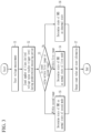
- FIG. 3 illustrates a flowchart of a diagnostic method according to an embodiment.
- the voltage measurer 110 may start measuring the voltage from the node ND (S1), and may transmit the measured voltage signal to the controller 120.
- the controller 120 may derive a voltage value based on the voltage signal and count the number of times the derived voltage value reaches the trigger level during a predetermined measuring period (S2).
- the controller 120 may generate a value indicating the number of times the trigger level is reached (hereinafter referred to as a "count value").
- steps S2 and S3 will be described with reference to FIG. 4 and FIG. 5 .
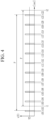
- FIG. 4 and FIG. 5 illustrate waveform diagrams of the voltage signals derived by the controller in step S2.
- the voltage signal may reach a trigger level VT once or more during a predetermined measuring period.
- the trigger level VT may indicate an arbitrary voltage value among values between highest and lowest values of the voltage values measured during the predetermined measuring period.
- the controller 120 may count the number of times a voltage value v reaches the trigger level VT from a start time point t1 of a predetermined measuring period P to an end time point t2 of the measuring period P.
- the voltage value v reaches the trigger level VT at time points t103, t104, t105, t106, t107, t108, t109, t110, t111, and t112. Accordingly, referring to FIG. 4 , the count value is 20 times.
- the controller 120 may count the number of times the voltage value v reaches the trigger level VT from a start time point t3 of the measuring period P to an end time point t4 of the measuring period P.
- the voltage value v reaches the trigger level VT at time points t203 and t204. Accordingly, referring to FIG. 5 , the count value is 2 times.
- the controller 120 may determine whether the count value is within the first range or the second range (S3).
- information of the first and second periods indicating the measuring cycle of each of the first and second modes may be previously stored.
- the controller 120 may receive information indicating the first and second periods from the BMS 400 through the communicator 130.
- the first range may be a range in which the BMS 400 normally operates corresponding to a case in which the measuring cycle of the BMS 400 is the first period.
- the first range may be, as shown in Equation 1 below, a range equal to or greater than a value obtained by dividing the measuring period P by the first period and multiplied by 2 and less than a value obtained by adding 2 to a value obtained by dividing the measuring period P by the first period and multiplied by 2.
- P is a measuring period for counting the number of times
- T1 is the first period corresponding to the first mode of the BMS 400
- Count is a value counted by the controller 120. Units of P and T1 may both be seconds.
- the first range is a range in which the count value is 20 or more and 22 or less.
- the controller 120 may determine that the count value is within the first range.
- the second range may be a range in which the BMS 400 normally operates corresponding to a case in which the measuring cycle of the BMS 400 is the second period.
- the second range may be a range equal to or greater than a value obtained by dividing the measuring period P by the second period and multiplied by 2 and less than a value obtained by adding 2 to a value obtained by dividing the measuring period P by the second period and multiplied by 2.
- P is a measuring period for counting the number of times
- T2 is the second period corresponding to the first mode of the BMS 400
- Count is a value counted by the controller 120. Units of P and T2 may both be seconds.
- the second range is a range in which the count value is 2 or more and 4 or less.
- the controller 120 may determine that the count value is within the second range.
- the reason that the value obtained by adding 2 to the minimum value in each of the first and second ranges is determined as the maximum value is because when the voltage value at the start time point and/or the end time point of the measuring period P is the same as the trigger level, the count value may exceed a value obtained by dividing the measuring period P by the first or second period T1 or T2 even when the BMS 400 is in a normal state.
- the start time point of the measuring period P is t102 and the end time point of the measuring period P is t122.
- the voltage value reaches the trigger level VT at time points t102, t103, t104, t105, t106, t107, t108, t109, t110, t111, and t112. Accordingly, the count value is 21 times.
- the start time point of the measuring period P is t202 and the end time point of the measuring period P is t204.
- the voltage value reaches the trigger level VT at time points t202, t203, and t204. Accordingly, the count value is 3 times.
- the controller 120 may determine the state of the BMS 400 as the normal state of the first mode (S4).
- the controller 120 may determine the state of the BMS 400 as the normal state of the second mode (S5).
- the controller 120 may determine the state of the BMS 400 as the abnormal state (S6).
- a voltage value being above the trigger level may indicate that the BMS is performing a measurement.
- the count value is within the first or second range.
- the controller 120 may determine that the BMS 400 is in an abnormal state.
- the state in which the BMS 400 normally operates is illustrated as a normal state of one of the first mode and the second mode, but the present disclosure is not limited thereto.
- the normal state of the BMS 400 may include respective normal states of two or more modes in which the BMS 400 operates at different cycles.
- the controller 120 may determine the state of the BMS 400 through one of steps S4 to S6 and generate a signal indicating the determined state of the BMS 400 (hereinafter referred to as a "BMS state signal").
- the BMS state signal may include information indicating a count value.
- the communicator 130 may transmit the BMS state signal to the output device 200.
- the output device 200 may receive the BMS state signal.
- the output device 200 may output a diagnostic result including a count value and information representing a state of the BMS 400 based on the BMS state signal (S7).
- the output device 200 may visually output the diagnostic result through a display.
- the output device 200 may provide a screen displaying the diagnostic result through an application and the like installed in the output device 200.
- a user may check the state of the BMS 400 through the output device 200 and, when the BMS 400 is in an abnormal state, may take countermeasures for the abnormal state.
Landscapes
- Physics & Mathematics (AREA)
- General Physics & Mathematics (AREA)
- Engineering & Computer Science (AREA)
- Manufacturing & Machinery (AREA)
- Chemical & Material Sciences (AREA)
- Chemical Kinetics & Catalysis (AREA)
- Electrochemistry (AREA)
- General Chemical & Material Sciences (AREA)
- Microelectronics & Electronic Packaging (AREA)
- Nonlinear Science (AREA)
- Power Engineering (AREA)
- Measurement Of Current Or Voltage (AREA)
Abstract
Description
- The present disclosure relates to a measuring device, a diagnostic system including the same, and a diagnostic method using the same.
- In a battery system, a battery management system (BMS) may be divided into several modes according to a cycle of measuring a voltage, a current, a temperature, and the like.
- The measuring cycle of the BMS may be used as an indicator for diagnosing whether the BMS is normally operating. However, in order to check the measuring cycle of the BMS, efforts such as displaying a specific signal on a screen by using equipment such as an oscilloscope and manipulating the screen and the equipment are required, and the work therefor may take excessive time.
- The present disclosure has been made in an effort to provide a measuring device that may check a measuring cycle of a BMS.
- The present disclosure has been made in an effort to provide a diagnostic system and a diagnostic method that may diagnose whether a BMS is normally operating according to a measuring cycle of the BMS.
- An embodiment provides a measuring device, including: a voltage measurer measuring a voltage from a node on a wire connected to a battery management system (BMS); and a controller that receives the measured voltage signal from the voltage measurer to derive a voltage value, counts the number of times the voltage value reaches a reference voltage during a measuring period, and determines a state of the BMS as one of a normal state of a first mode, a normal state of a second mode, and an abnormal state based on the number of times.
- The wire may be a wire connected to one end of a thermistor. The first mode is a power mode in which the BMS measures a temperature from the thermistor at a cycle of a first period. The second mode is a power mode in which the BMS measures the temperature from the thermistor at a cycle of a second period longer than the first period.
- When the number of times is within a first range in which a value obtained by dividing the measuring period by the first period and multiplied by 2 is a minimum value and a value obtained by adding 2 to the minimum value is a maximum value, the controller may determine the state of the BMS as the normal state of the first mode.
- When the number of times is within a second range in which a value obtained by dividing the measuring period by the second period and multiplied by 2 is a minimum value and a value obtained by adding 2 to the minimum value is a maximum value, the controller may determine the state of the BMS as the normal state of the second mode.
- The controller may determine the state of the BMS as the abnormal state when the number is not within the first and second ranges.
- Another embodiment provides a diagnostic system, including: a measuring device that measures a voltage from a node on a wire connected to a battery management system (BMS), derives a voltage value from the measured voltage signal, counts the number of times the voltage value reaches a reference voltage during a measuring period, and determines a state of the BMS as one of a normal state of a first mode, a normal state of a second mode, and an abnormal state based on the number of times; and an output device that receives a signal indicating the state of the BMS from the measuring device, and outputs a diagnostic result including the state of the BMS based on the signal indicating the state of the BMS.
- The wire may be a wire connected to one end of a thermistor. The first mode is a power mode in which the BMS measures a temperature from the thermistor at a cycle of a first period. The second mode is a power mode in which the BMS measures the temperature from the thermistor at a cycle of a second period longer than the first period.
- When the number of times is within a first range in which a value obtained by dividing the measuring period by the first period and multiplied by 2 is a minimum value and a value obtained by adding 2 to the minimum value is a maximum value, the measuring device may determine the state of the BMS as the normal state of the first mode.
- When the number of times is within a second range in which a value obtained by dividing the measuring period by the second period and multiplied by 2 is a minimum value and a value obtained by adding 2 to the minimum value is a maximum value, the measuring device may determine the state of the BMS as the normal state of the second mode.
- The measuring device may determine the state of the BMS as the abnormal state when the number is not within the first and second ranges.
- The output device may include a display that visually outputs the diagnostic result.
- Another embodiment provides a diagnostic method, including: measuring a voltage from a node on a wire connected to a battery management system (BMS); deriving a voltage value based on the measured voltage and counting the number of times the voltage value reaches a reference voltage during a measuring period; determining whether the number of times is within a first or second range; and determining the state of the BMS as one of a normal state of a first mode, a normal state of a second mode, and an abnormal state based on the determined result.
- The wire may be a wire connected to one end of a thermistor. The first mode is a power mode in which the BMS measures a temperature from the thermistor at a cycle of a first period. The second mode is a power mode in which the BMS measures the temperature from the thermistor at a cycle of a second period longer than the first period.
- The first range may be a range in which a value obtained by dividing the measuring period by the first period and multiplied by 2 is a minimum value and a value obtained by adding 2 to the minimum value is a maximum value.
- The determining of the state of the BMS as one of the normal state of the first mode, the normal state of the second mode, and the abnormal state: may include determining, when the number of times is within the first range, the state of the BMS as the normal state of the first mode.
- The second range may be a range in which a value obtained by dividing the measuring period by the second period and multiplied by 2 is a minimum value and a value obtained by adding 2 to the minimum value is a maximum value.
- The determining of the state of the BMS as one of the normal state of the first mode, the normal state of the second mode, and the abnormal state: may include determining, when the number of times is within the second range, the state of the BMS as the normal state of the second mode.
- The determining of the state of the BMS as one of the normal state of the first mode, the normal state of the second mode, and the abnormal state may include determining the state of the BMS as the abnormal state when the number is not within the first and second ranges.
- The diagnostic method may further include outputting a diagnostic result including the state of the BMS determined as one of the normal state of the first mode, the normal state of the second mode, and the abnormal state.
- The outputting of the diagnostic result may include visually outputting the state of the BMS and the number of times through a display.
- According to the present disclosure, it is possible to diagnose whether a BMS normally operates by checking a measuring cycle of the BMS.
- According to the present disclosure, it is possible to improve accuracy of mode determination by determining a power mode of a BMS based on a measuring cycle of the BMS.
- At least some of the above and other features of the invention are set out in the claims.
-
-
FIG. 1 illustrates a block diagram of a diagnostic system according to an embodiment. -
FIG. 2 is a block diagram for explaining a battery system to which a voltage measurer ofFIG. 1 is connected. -
FIG. 3 illustrates a flowchart of a diagnostic method according to an embodiment. -
FIG. 4 andFIG. 5 illustrate waveform diagrams of voltage signals derived by a controller in step S2 ofFIG. 3 . - Hereinafter, embodiments disclosed in the present specification will be described in detail with reference to the accompanying drawings, and in the present specification, the same or similar constituent elements will be denoted by the same or similar reference numerals, and a redundant description thereof will be omitted. The terms "module" and/or "unit, portion, or part" representing constituent element used in the following description are used only in order to make understanding of the specification easier, and thus, these terms do not have meanings or roles that distinguish them from each other by themselves. In addition, in describing embodiments of the present specification, when it is determined that a detailed description of the well-known art associated with the present disclosure may obscure the gist of the present disclosure, it will be omitted. Further, the accompanying drawings are provided only in order to allow embodiments disclosed in the present specification to be easily understood and are not to be interpreted as limiting the present specification, and it is to be understood that the present disclosure includes all modifications, equivalents, and substitutions without departing from the scope of the present disclosure.
- Terms including ordinal numbers such as first, second, and the like will be used only to describe various constituent elements, and are not to be interpreted as limiting these constituent elements. The terms are only used to differentiate one constituent element from other constituent elements.
- In the present application, it should be understood that the term "include", "comprise", "have", or "configure" indicates that a feature, a number, a step, an operation, a constituent element, a part, or a combination thereof described in the specification is present, but does not exclude a possibility of presence or addition of one or more other features, numbers, steps, operations, constituent elements, parts, or combinations, in advance.
- A program implemented as a set of instructions embodying a control algorithm necessary for controlling another component may be installed in a component for controlling another component under a specific control condition among components according to an embodiment. A control component may generate output data by processing input data and stored data according to the installed program. The control component may include a non-volatile memory for storing a program and a memory for storing data.
-
FIG. 1 illustrates a block diagram of a diagnostic system according to an embodiment. - Referring to
FIG. 1 , a system 1 (hereinafter referred to as a "diagnostic system") for diagnosing a battery management system (BMS) is connected to a battery system including the BMS to measure a voltage at a connected node, diagnose a state of the BMS based on the measured voltage value, and output a screen displaying the diagnosed result. Thediagnostic system 1 may include ameasuring device 100 and anoutput device 200. - The measuring
device 100 may measure a voltage at a node ND, and may transmit a result of diagnosing the state of the BMS based on the measured voltage to theoutput device 200. Here, the node ND may be a node on a wire connected to the BMS. The measuringdevice 100 may include avoltage measurer 110, acontroller 120, and acommunicator 130. - The
voltage measurer 110 may measure a voltage from the node ND, and may generate a signal (hereinafter referred to as a "voltage signal") representing the measured voltage to transmit it to thecontroller 120. - The
controller 120 may derive a voltage value based on the voltage signal received from thevoltage measurer 110. Deriving the voltage value may comprise the step of outputting a voltage value that has a positive level at the times when a voltage signal is measured at the node ND. Thecontroller 120 may determine whether the voltage value reaches a trigger level indicating a predetermined reference voltage during a predetermined measuring period, may count the number of times the voltage value reaches the trigger level (for example, determine the number of times the voltage value crosses the trigger level), and may determine a state of the BMS based on a count result for a predetermined measuring period. For example, the predetermined measuring period may be 10 seconds. - The state of the BMS may be either a normal state indicating a normally operating state or an abnormal state indicating a non-normal operating state. The normal state may be a normal state of one of a plurality of power modes according to a cycle in which the BMS measures a voltage, a temperature, a current, and the like of the battery. Hereinafter, for convenience of description, it is assumed that the plurality of power modes are modes according to a cycle in which the BMS measures the temperature of the battery through a thermistor.
- In the embodiment, the plurality of power modes may include a first mode and a second mode. The first mode is a mode in which the BMS periodically measures the temperature through the thermistor every first period. That is, in the first mode, the BMS may repeat an operation of measuring the temperature through the thermistor at a time interval of the first period. The first mode may be referred to as an active or normal mode. The second mode is a mode in which the BMS periodically measures the temperature through the thermistor every second period. That is, in the second mode, the BMS may repeat an operation of measuring the temperature through the thermistor at a time interval of the second period. The second mode may be referred to as a sleep or standby mode. Here, the second period may be longer than the first period. For example, the first period may be 1 second, and the second period may be 10 seconds.
- In the embodiment, the
controller 120 may determine the state of the BMS as a normal state in the first mode, a normal state in the second mode, or an abnormal state, based on the count result. - For example, the
controller 120 may determine a first range in which a value obtained by dividing a predetermined measuring period by the first period and multiplied by 2 is taken as a minimum value, and a value obtained by adding 2 to the minimum value is taken as a maximum value; and when the count result during the predetermined measuring period is within the first range, thecontroller 120 may determine the state of the BMS as a normal state in the first mode in which the voltage measuring cycle is the first period. Thecontroller 120 may determine a second range in which a value obtained by dividing a predetermined measuring period by the second period and multiplied by 2 is taken as a minimum value, and a value obtained by adding 2 to the minimum value is taken as a maximum value; and when the count result during the predetermined measuring period is within the second range, thecontroller 120 may determine the state of the BMS as a normal state in the second mode in which the voltage measuring cycle is the second period. Thecontroller 120 may determine the state of the BMS as the abnormal state when the count result during the predetermined measuring period is not within the first range or the second range. - The
communicator 130 may transmit and receive signals to and from an external device such as theoutput device 200 through wired or wireless communication with the external device. - The
output device 200 may output a diagnosed result based on the signal received from themeasurer 100. Theoutput device 200 may include a display that visually outputs the diagnosed result. In addition, the output device may include a speaker that outputs the diagnosed result as sound. The diagnosed result may include information indicating the number of times the voltage value measured by themeasurer 100 reaches the trigger level and/or the state of the BMS. - Hereinafter, a state in which the
diagnostic system 1 is connected to a wire connected to a BMS will be described with reference toFIG. 2 . -
FIG. 2 is a block diagram for explaining a battery system to which the voltage measurer ofFIG. 1 is connected. - A
battery system 3 may include abattery pack 300, aBMS 400, athermistor 500, and relays 600 and 601. - An
external device 4 may include a load such as an inverter and a converter, and/or a charging device. When theexternal device 4 is a charging device, respective ends of thebattery system 3 are connected to the charging device, so that thebattery system 3 may be charged by receiving power from the charging device. When theexternal device 4 is a load, respective ends of thebattery system 3 are connected to the load, so that power supplied by thebattery pack 300 may be discharged through the load. - The
battery pack 300 may generate a voltage measuring signal VS indicating a cell voltage of each of a plurality ofbattery cells 301 to 303 to transmit it to theBMS 400. TheBMS 400 may obtain a voltage measuring signal VS from thebattery pack 300 through a pin P1. - The
battery pack 300 may include a plurality ofbattery cells 301 to 303. AlthoughFIG. 2 illustrates that the number of a plurality ofbattery cells 301 to 303 is three, the present disclosure is not limited thereto, and thebattery pack 300 may be implemented with 2 or more battery cells connected in series, a plurality of battery cells in which two or more battery cells connected in parallel are connected in series, or two or more battery cells connected in parallel. - The
thermistor 500 may sense the pack temperature of thebattery pack 300 to generate a temperature measuring signal TS, and may transmit the temperature measuring signal TS to theBMS 400. Here, the temperature measuring signal TS may indicate a voltage value determined according to the measured temperature. One end of thethermistor 500 is connected to pin P2, and the other end of thethermistor 500 is connected to the ground. TheBMS 400 may obtain the temperature measuring signal TS from thethermistor 500 through a pin P2. - One end of each of the
relays battery pack 300, and the other end of each of therelays external device 4. Closing and opening of therelays BMS 400. - The node ND may be disposed on a wire connected between one end of the
thermistor 500 and the pin P2. Thevoltage measurer 110 may be electrically connected to the node ND to measure the voltage of the node ND, and may generate a voltage signal representing the measured voltage. - The
BMS 400 may periodically receive the temperature measuring signal TS according to a predetermined measuring cycle. The predetermined measuring cycle may be determined according to the state of theBMS 400. The predetermined measuring cycle may include the first period in the first mode, the second period in the second mode, and the like. - When the
BMS 400 performs an operation of reading the temperature measuring signal TS from thethermistor 500 through the pin P2, the voltage of the node ND may be changed. Thevoltage measurer 110 may measure the changed voltage of the node ND. - Hereinafter, a method of diagnosing the state of the BMS based on the voltage measured by the
diagnostic system 1 will be described with reference toFIG. 3 to FIG. 5 . -
FIG. 3 illustrates a flowchart of a diagnostic method according to an embodiment. - The
voltage measurer 110 may start measuring the voltage from the node ND (S1), and may transmit the measured voltage signal to thecontroller 120. - The
controller 120 may derive a voltage value based on the voltage signal and count the number of times the derived voltage value reaches the trigger level during a predetermined measuring period (S2). Thecontroller 120 may generate a value indicating the number of times the trigger level is reached (hereinafter referred to as a "count value"). Hereinafter, steps S2 and S3 will be described with reference toFIG. 4 andFIG. 5 . -
FIG. 4 andFIG. 5 illustrate waveform diagrams of the voltage signals derived by the controller in step S2. - The voltage signal may reach a trigger level VT once or more during a predetermined measuring period. The trigger level VT may indicate an arbitrary voltage value among values between highest and lowest values of the voltage values measured during the predetermined measuring period.
- According to the waveform diagram shown in
FIG. 4 , thecontroller 120 may count the number of times a voltage value v reaches the trigger level VT from a start time point t1 of a predetermined measuring period P to an end time point t2 of the measuring period P. The voltage value v reaches the trigger level VT at time points t103, t104, t105, t106, t107, t108, t109, t110, t111, and t112. Accordingly, referring toFIG. 4 , the count value is 20 times. - In addition, according to the waveform diagram shown in
FIG. 5 , thecontroller 120 may count the number of times the voltage value v reaches the trigger level VT from a start time point t3 of the measuring period P to an end time point t4 of the measuring period P. The voltage value v reaches the trigger level VT at time points t203 and t204. Accordingly, referring toFIG. 5 , the count value is 2 times. - When the predetermined measuring period P ends, the
controller 120 may determine whether the count value is within the first range or the second range (S3). In thecontroller 120, information of the first and second periods indicating the measuring cycle of each of the first and second modes may be previously stored. Alternatively, thecontroller 120 may receive information indicating the first and second periods from theBMS 400 through thecommunicator 130. - The first range may be a range in which the
BMS 400 normally operates corresponding to a case in which the measuring cycle of theBMS 400 is the first period. The first range may be, as shown inEquation 1 below, a range equal to or greater than a value obtained by dividing the measuring period P by the first period and multiplied by 2 and less than a value obtained by adding 2 to a value obtained by dividing the measuring period P by the first period and multiplied by 2.
- Here, P is a measuring period for counting the number of times, T1 is the first period corresponding to the first mode of the
BMS 400, and Count is a value counted by thecontroller 120. Units of P and T1 may both be seconds. - For example, when the first period T1 is 1 second and the measuring period P is 10 seconds, the first range is a range in which the count value is 20 or more and 22 or less. In the example of
FIG. 4 , since the count value is 20 times, thecontroller 120 may determine that the count value is within the first range. - The second range may be a range in which the
BMS 400 normally operates corresponding to a case in which the measuring cycle of theBMS 400 is the second period. As shown inEquation 2 below, the second range may be a range equal to or greater than a value obtained by dividing the measuring period P by the second period and multiplied by 2 and less than a value obtained by adding 2 to a value obtained by dividing the measuring period P by the second period and multiplied by 2.
- Here, P is a measuring period for counting the number of times, T2 is the second period corresponding to the first mode of the
BMS 400, and Count is a value counted by thecontroller 120. Units of P and T2 may both be seconds. - For example, when the second period T2 is 10 seconds and the measuring period P is 10 seconds, the second range is a range in which the count value is 2 or more and 4 or less. In the example of
FIG. 5 , since the count value is 2 times, thecontroller 120 may determine that the count value is within the second range. - The reason that the value obtained by adding 2 to the minimum value in each of the first and second ranges is determined as the maximum value is because when the voltage value at the start time point and/or the end time point of the measuring period P is the same as the trigger level, the count value may exceed a value obtained by dividing the measuring period P by the first or second period T1 or T2 even when the
BMS 400 is in a normal state. - For example, in
FIG. 4 , it is assumed that the start time point of the measuring period P is t102 and the end time point of the measuring period P is t122. The voltage value reaches the trigger level VT at time points t102, t103, t104, t105, t106, t107, t108, t109, t110, t111, and t112. Accordingly, the count value is 21 times. - In addition, for example, in
FIG. 5 , it is assumed that the start time point of the measuring period P is t202 and the end time point of the measuring period P is t204. The voltage value reaches the trigger level VT at time points t202, t203, and t204. Accordingly, the count value is 3 times. - When the count value is within the first range, the
controller 120 may determine the state of theBMS 400 as the normal state of the first mode (S4). When the count value is within the second range, thecontroller 120 may determine the state of theBMS 400 as the normal state of the second mode (S5). When the count value is not within the first and second ranges, thecontroller 120 may determine the state of theBMS 400 as the abnormal state (S6). - A voltage value being above the trigger level may indicate that the BMS is performing a measurement. In the normal state in which the
BMS 400 normally operates, since the measuring cycle is the first or second period, the count value is within the first or second range. When the count value is not within the first and second ranges, since the measuring cycle of theBMS 400 is different from the first or second period, thecontroller 120 may determine that theBMS 400 is in an abnormal state. - In
FIG. 3 , the state in which theBMS 400 normally operates is illustrated as a normal state of one of the first mode and the second mode, but the present disclosure is not limited thereto. The normal state of theBMS 400 may include respective normal states of two or more modes in which theBMS 400 operates at different cycles. - The
controller 120 may determine the state of theBMS 400 through one of steps S4 to S6 and generate a signal indicating the determined state of the BMS 400 (hereinafter referred to as a "BMS state signal"). The BMS state signal may include information indicating a count value. Thecommunicator 130 may transmit the BMS state signal to theoutput device 200. - The
output device 200 may receive the BMS state signal. Theoutput device 200 may output a diagnostic result including a count value and information representing a state of theBMS 400 based on the BMS state signal (S7). Theoutput device 200 may visually output the diagnostic result through a display. Theoutput device 200 may provide a screen displaying the diagnostic result through an application and the like installed in theoutput device 200. - A user may check the state of the
BMS 400 through theoutput device 200 and, when theBMS 400 is in an abnormal state, may take countermeasures for the abnormal state. - While the embodiment of the present disclosure has been described in connection with what is presently considered to be practical embodiments, it is to be understood that the disclosure is not limited to the disclosed embodiments, but, on the contrary, is intended to cover various modifications and equivalent arrangements included within the scope of the appended claims.
-
- 1: diagnostic system
- 100: measuring device
- 110: voltage measurer
- 120: controller
- 130: communicator
- 200: output device
- 3: battery system
- 300: battery pack
- 301, 302, 303: battery cell
- 400: battery management system (BMS)
- 500: thermistor
- 600, 601: relay
- 4: external device
Claims (15)
- A measuring device, comprising:a voltage measurer configured to measure a voltage from a node on a wire connected to a battery management system (BMS); anda controller configured to receive the measured voltage signal from the voltage measurer to derive a voltage value, to count the number of times the voltage value reaches a reference voltage during a measuring period, and to determine a state of the BMS as one of a normal state of a first mode, a normal state of a second mode, and an abnormal state based on the number of times.
- The measuring device of claim 1, whereinthe wire is a wire connected to one end of a thermistor,the first mode is a power mode in which the BMS measures a temperature from the thermistor at a cycle of a first period, andthe second mode is a power mode in which the BMS measures the temperature from the thermistor at a cycle of a second period longer than the first period.
- The measuring device of claim 2, wherein
when the number of times is within a first range in which a value obtained by dividing the measuring period by the first period and multiplied by 2 is a minimum value and a value obtained by adding 2 to the minimum value is a maximum value, the controller determines the state of the BMS as the normal state of the first mode. - The measuring device of claim 3, wherein
when the number of times is within a second range in which a value obtained by dividing the measuring period by the second period and multiplied by 2 is a minimum value and a value obtained by adding 2 to the minimum value is a maximum value, the controller determines the state of the BMS as the normal state of the second mode. - The measuring device of claim 4, wherein
the controller determines the state of the BMS as the abnormal state when the number is not within the first and second ranges. - A diagnostic system, comprising:a measuring device according to any one of claims 1 - 5; andan output device that receives a signal indicating the state of the BMS from the measuring device, and outputs a diagnostic result including the state of the BMS based on the signal indicating the state of the BMS.
- The diagnostic system of claim 6, wherein
the output device includes a display that visually outputs the diagnostic result. - A diagnostic method, comprising:measuring a voltage from a node on a wire connected to a battery management system (BMS);deriving a voltage value based on the measured voltage and counting the number of times the voltage value reaches a reference voltage during a measuring period;determining whether the number of times is within a first or second range; anddetermining the state of the BMS as one of a normal state of a first mode, a normal state of a second mode, and an abnormal state based on the determined result.
- The diagnostic method of claim 8, whereinthe wire is a wire connected to one end of a thermistor,the first mode is a power mode in which the BMS measures a temperature from the thermistor at a cycle of a first period, andthe second mode is a power mode in which the BMS measures the temperature from the thermistor at a cycle of a second period longer than the first period.
- The diagnostic method of claim 9, wherein
the first range is a range in which a value obtained by dividing the measuring period by the first period and multiplied by 2 is a minimum value and a value obtained by adding 2 to the minimum value is a maximum value. - The diagnostic method of claim 10, whereinthe determining of the state of the BMS as one of the normal state of the first mode, the normal state of the second mode, and the abnormal state includesdetermining, when the number of times is within the first range, the state of the BMS as the normal state of the first mode.
- The diagnostic method of any one of claims 9 - 11, wherein
the second range is a range in which a value obtained by dividing the measuring period by the second period and multiplied by 2 is a minimum value and a value obtained by adding 2 to the minimum value is a maximum value. - The diagnostic method of claim 12, whereinthe determining of the state of the BMS as one of the normal state of the first mode, the normal state of the second mode, and the abnormal state includesdetermining, when the number of times is within the second range, the state of the BMS as the normal state of the second mode.
- The diagnostic method of any one of claims 8 - 13, whereinthe determining of the state of the BMS as one of the normal state of the first mode, the normal state of the second mode, and the abnormal state includesdetermining the state of the BMS as the abnormal state when the number is not within the first or second ranges.
- The diagnostic method of claim 8 - 14, further comprising
outputting a diagnostic result including the state of the BMS determined as one of the normal state of the first mode, the normal state of the second mode, and the abnormal state wherein, optionally, the outputting of the diagnostic result includes visually outputting the state of the BMS and the number of times through a display.
Applications Claiming Priority (1)
| Application Number | Priority Date | Filing Date | Title |
|---|---|---|---|
| KR1020220169003A KR20240084301A (en) | 2022-12-06 | 2022-12-06 | Measuring device, diagnostic system including the same, and diagnostic method using the same |
Publications (2)
| Publication Number | Publication Date |
|---|---|
| EP4382922A1 true EP4382922A1 (en) | 2024-06-12 |
| EP4382922B1 EP4382922B1 (en) | 2025-06-25 |
Family
ID=88511596
Family Applications (1)
| Application Number | Title | Priority Date | Filing Date |
|---|---|---|---|
| EP23205548.3A Active EP4382922B1 (en) | 2022-12-06 | 2023-10-24 | Measuring device, diagnostic system including the same, and diagnostic method using the same |
Country Status (5)
| Country | Link |
|---|---|
| US (1) | US20240183910A1 (en) |
| EP (1) | EP4382922B1 (en) |
| KR (1) | KR20240084301A (en) |
| HU (1) | HUE072543T2 (en) |
| PL (1) | PL4382922T3 (en) |
Citations (5)
| Publication number | Priority date | Publication date | Assignee | Title |
|---|---|---|---|---|
| US20160291114A1 (en) * | 2013-11-21 | 2016-10-06 | Commissariat à l'énergie atomique et aux énergies alternatives | Method for detecting a malfunction of a battery control system |
| CN109541489A (en) * | 2017-09-21 | 2019-03-29 | 三星Sdi株式会社 | Battery pack diagnostic device |
| KR20190042340A (en) * | 2017-10-16 | 2019-04-24 | 주식회사 엘지화학 | Diagnosis system and method of a battery pack through control of a vehicle-mounted charger |
| US20200200805A1 (en) * | 2018-12-20 | 2020-06-25 | Qorvo Us, Inc. | Electrical current measurement circuit |
| KR20200107813A (en) * | 2019-03-06 | 2020-09-16 | 주식회사 엘지화학 | Battery management system, method for checking the system |
Family Cites Families (3)
| Publication number | Priority date | Publication date | Assignee | Title |
|---|---|---|---|---|
| KR102833360B1 (en) * | 2021-10-28 | 2025-07-11 | 주식회사 엘지에너지솔루션 | Battery management apparatus and operating method of the same |
| KR20230076683A (en) * | 2021-11-24 | 2023-05-31 | 현대모비스 주식회사 | Battery management systems and method for battery manaing using the same |
| KR20230157557A (en) * | 2022-05-09 | 2023-11-17 | 현대자동차주식회사 | System and method for diagnosis battery of vehicle using big data |
-
2022
- 2022-12-06 KR KR1020220169003A patent/KR20240084301A/en active Pending
-
2023
- 2023-10-24 HU HUE23205548A patent/HUE072543T2/en unknown
- 2023-10-24 EP EP23205548.3A patent/EP4382922B1/en active Active
- 2023-10-24 PL PL23205548.3T patent/PL4382922T3/en unknown
- 2023-10-27 US US18/496,565 patent/US20240183910A1/en active Pending
Patent Citations (5)
| Publication number | Priority date | Publication date | Assignee | Title |
|---|---|---|---|---|
| US20160291114A1 (en) * | 2013-11-21 | 2016-10-06 | Commissariat à l'énergie atomique et aux énergies alternatives | Method for detecting a malfunction of a battery control system |
| CN109541489A (en) * | 2017-09-21 | 2019-03-29 | 三星Sdi株式会社 | Battery pack diagnostic device |
| KR20190042340A (en) * | 2017-10-16 | 2019-04-24 | 주식회사 엘지화학 | Diagnosis system and method of a battery pack through control of a vehicle-mounted charger |
| US20200200805A1 (en) * | 2018-12-20 | 2020-06-25 | Qorvo Us, Inc. | Electrical current measurement circuit |
| KR20200107813A (en) * | 2019-03-06 | 2020-09-16 | 주식회사 엘지화학 | Battery management system, method for checking the system |
Also Published As
| Publication number | Publication date |
|---|---|
| US20240183910A1 (en) | 2024-06-06 |
| PL4382922T3 (en) | 2025-09-22 |
| EP4382922B1 (en) | 2025-06-25 |
| HUE072543T2 (en) | 2025-11-28 |
| KR20240084301A (en) | 2024-06-13 |
Similar Documents
| Publication | Publication Date | Title |
|---|---|---|
| EP3958006B1 (en) | Battery diagnosis apparatus and method | |
| US11815558B2 (en) | Apparatus and method for diagnosing abnormal degradated battery cell | |
| US12360166B2 (en) | Battery diagnosis apparatus, battery pack, electric vehicle and battery diagnosis method | |
| US11121415B2 (en) | Monitoring system for series-connected battery cells | |
| JP2022532545A (en) | Battery cell diagnostic device and method | |
| US20240003980A1 (en) | Battery management apparatus and method | |
| JP7543552B2 (en) | Battery diagnostic device, battery system, and battery diagnostic method | |
| KR20190083915A (en) | Apparatus for diagnosing pack current measurement unit | |
| KR20190033279A (en) | Battery pack diagnostic apparatus | |
| EP4542246A1 (en) | Battery diagnosis method, and battery diagnosis device and battery system providing same method | |
| EP4549968B1 (en) | Battery diagnosis apparatus, battery diagnosis method, battery pack, and vehicle | |
| KR20220013167A (en) | Fault cell diagnosis method and battery system using the same | |
| JP2003068366A (en) | Sensor abnormality detection device | |
| US20250189591A1 (en) | Battery diagnosis method, battery diagnosis apparatus and battery system providing the same | |
| KR20200088153A (en) | apparatus for checking current sensor, and battery pack including the apparatus | |
| EP4382922B1 (en) | Measuring device, diagnostic system including the same, and diagnostic method using the same | |
| EP4600680B1 (en) | Apparatus and method for diagnosing a battery | |
| JP2010008133A (en) | Portable charger, and deterioration diagnosis method of secondary battery used therefor | |
| EP4386406B1 (en) | Battery diagnosis method, and battery diagnosis apparatus and battery system providing same | |
| JP5843518B2 (en) | Disconnection detector | |
| KR20220112502A (en) | Learning method of cell voltage deviation prediction model, and cell balancing method and battery system using the same | |
| US20240426924A1 (en) | Calibration Method of State of Charge, and Battery System for Providing the Same | |
| US20250123332A1 (en) | Battery management apparatus and operating method of the same | |
| KR102893868B1 (en) | Battery diagnostic apparatus and method using electrochemical-impedance-spectroscopy in all-solid-state batteries | |
| US20260126496A1 (en) | Device for diagnosing a state of a battery and method thereof |
Legal Events
| Date | Code | Title | Description |
|---|---|---|---|
| PUAI | Public reference made under article 153(3) epc to a published international application that has entered the european phase |
Free format text: ORIGINAL CODE: 0009012 |
|
| STAA | Information on the status of an ep patent application or granted ep patent |
Free format text: STATUS: REQUEST FOR EXAMINATION WAS MADE |
|
| 17P | Request for examination filed |
Effective date: 20231024 |
|
| AK | Designated contracting states |
Kind code of ref document: A1 Designated state(s): AL AT BE BG CH CY CZ DE DK EE ES FI FR GB GR HR HU IE IS IT LI LT LU LV MC ME MK MT NL NO PL PT RO RS SE SI SK SM TR |
|
| GRAP | Despatch of communication of intention to grant a patent |
Free format text: ORIGINAL CODE: EPIDOSNIGR1 |
|
| STAA | Information on the status of an ep patent application or granted ep patent |
Free format text: STATUS: GRANT OF PATENT IS INTENDED |
|
| INTG | Intention to grant announced |
Effective date: 20250124 |
|
| GRAS | Grant fee paid |
Free format text: ORIGINAL CODE: EPIDOSNIGR3 |
|
| GRAA | (expected) grant |
Free format text: ORIGINAL CODE: 0009210 |
|
| STAA | Information on the status of an ep patent application or granted ep patent |
Free format text: STATUS: THE PATENT HAS BEEN GRANTED |
|
| AK | Designated contracting states |
Kind code of ref document: B1 Designated state(s): AL AT BE BG CH CY CZ DE DK EE ES FI FR GB GR HR HU IE IS IT LI LT LU LV MC ME MK MT NL NO PL PT RO RS SE SI SK SM TR |
|
| REG | Reference to a national code |
Ref country code: GB Ref legal event code: FG4D |
|
| REG | Reference to a national code |
Ref country code: CH Ref legal event code: EP |
|
| REG | Reference to a national code |
Ref country code: DE Ref legal event code: R096 Ref document number: 602023004292 Country of ref document: DE |
|
| REG | Reference to a national code |
Ref country code: CH Ref legal event code: EP |
|
| REG | Reference to a national code |
Ref country code: IE Ref legal event code: FG4D |
|
| PG25 | Lapsed in a contracting state [announced via postgrant information from national office to epo] |
Ref country code: FI Free format text: LAPSE BECAUSE OF FAILURE TO SUBMIT A TRANSLATION OF THE DESCRIPTION OR TO PAY THE FEE WITHIN THE PRESCRIBED TIME-LIMIT Effective date: 20250625 |
|
| REG | Reference to a national code |
Ref country code: LT Ref legal event code: MG9D |
|
| PG25 | Lapsed in a contracting state [announced via postgrant information from national office to epo] |
Ref country code: NO Free format text: LAPSE BECAUSE OF FAILURE TO SUBMIT A TRANSLATION OF THE DESCRIPTION OR TO PAY THE FEE WITHIN THE PRESCRIBED TIME-LIMIT Effective date: 20250925 Ref country code: GR Free format text: LAPSE BECAUSE OF FAILURE TO SUBMIT A TRANSLATION OF THE DESCRIPTION OR TO PAY THE FEE WITHIN THE PRESCRIBED TIME-LIMIT Effective date: 20250926 |
|
| PG25 | Lapsed in a contracting state [announced via postgrant information from national office to epo] |
Ref country code: BG Free format text: LAPSE BECAUSE OF FAILURE TO SUBMIT A TRANSLATION OF THE DESCRIPTION OR TO PAY THE FEE WITHIN THE PRESCRIBED TIME-LIMIT Effective date: 20250625 |
|
| PG25 | Lapsed in a contracting state [announced via postgrant information from national office to epo] |
Ref country code: HR Free format text: LAPSE BECAUSE OF FAILURE TO SUBMIT A TRANSLATION OF THE DESCRIPTION OR TO PAY THE FEE WITHIN THE PRESCRIBED TIME-LIMIT Effective date: 20250625 |
|
| PGFP | Annual fee paid to national office [announced via postgrant information from national office to epo] |
Ref country code: FR Payment date: 20250930 Year of fee payment: 3 |
|
| PG25 | Lapsed in a contracting state [announced via postgrant information from national office to epo] |
Ref country code: RS Free format text: LAPSE BECAUSE OF FAILURE TO SUBMIT A TRANSLATION OF THE DESCRIPTION OR TO PAY THE FEE WITHIN THE PRESCRIBED TIME-LIMIT Effective date: 20250925 |
|
| PG25 | Lapsed in a contracting state [announced via postgrant information from national office to epo] |
Ref country code: LV Free format text: LAPSE BECAUSE OF FAILURE TO SUBMIT A TRANSLATION OF THE DESCRIPTION OR TO PAY THE FEE WITHIN THE PRESCRIBED TIME-LIMIT Effective date: 20250625 |
|
| REG | Reference to a national code |
Ref country code: NL Ref legal event code: MP Effective date: 20250625 |
|
| PG25 | Lapsed in a contracting state [announced via postgrant information from national office to epo] |
Ref country code: NL Free format text: LAPSE BECAUSE OF FAILURE TO SUBMIT A TRANSLATION OF THE DESCRIPTION OR TO PAY THE FEE WITHIN THE PRESCRIBED TIME-LIMIT Effective date: 20250625 |
|
| REG | Reference to a national code |
Ref country code: HU Ref legal event code: AG4A Ref document number: E072543 Country of ref document: HU |
|
| PG25 | Lapsed in a contracting state [announced via postgrant information from national office to epo] |
Ref country code: PT Free format text: LAPSE BECAUSE OF FAILURE TO SUBMIT A TRANSLATION OF THE DESCRIPTION OR TO PAY THE FEE WITHIN THE PRESCRIBED TIME-LIMIT Effective date: 20251027 |
|
| PGFP | Annual fee paid to national office [announced via postgrant information from national office to epo] |
Ref country code: HU Payment date: 20251105 Year of fee payment: 3 |
|
| REG | Reference to a national code |
Ref country code: AT Ref legal event code: MK05 Ref document number: 1806971 Country of ref document: AT Kind code of ref document: T Effective date: 20250625 |
|
| PG25 | Lapsed in a contracting state [announced via postgrant information from national office to epo] |
Ref country code: IS Free format text: LAPSE BECAUSE OF FAILURE TO SUBMIT A TRANSLATION OF THE DESCRIPTION OR TO PAY THE FEE WITHIN THE PRESCRIBED TIME-LIMIT Effective date: 20251025 |
|
| PGFP | Annual fee paid to national office [announced via postgrant information from national office to epo] |
Ref country code: DE Payment date: 20250930 Year of fee payment: 3 |
|
| PG25 | Lapsed in a contracting state [announced via postgrant information from national office to epo] |
Ref country code: AT Free format text: LAPSE BECAUSE OF FAILURE TO SUBMIT A TRANSLATION OF THE DESCRIPTION OR TO PAY THE FEE WITHIN THE PRESCRIBED TIME-LIMIT Effective date: 20250625 Ref country code: SM Free format text: LAPSE BECAUSE OF FAILURE TO SUBMIT A TRANSLATION OF THE DESCRIPTION OR TO PAY THE FEE WITHIN THE PRESCRIBED TIME-LIMIT Effective date: 20250625 |
|
| PG25 | Lapsed in a contracting state [announced via postgrant information from national office to epo] |
Ref country code: CZ Free format text: LAPSE BECAUSE OF FAILURE TO SUBMIT A TRANSLATION OF THE DESCRIPTION OR TO PAY THE FEE WITHIN THE PRESCRIBED TIME-LIMIT Effective date: 20250625 |
|
| PGFP | Annual fee paid to national office [announced via postgrant information from national office to epo] |
Ref country code: PL Payment date: 20251014 Year of fee payment: 3 |
|
| PG25 | Lapsed in a contracting state [announced via postgrant information from national office to epo] |
Ref country code: EE Free format text: LAPSE BECAUSE OF FAILURE TO SUBMIT A TRANSLATION OF THE DESCRIPTION OR TO PAY THE FEE WITHIN THE PRESCRIBED TIME-LIMIT Effective date: 20250625 |
|
| PG25 | Lapsed in a contracting state [announced via postgrant information from national office to epo] |
Ref country code: SK Free format text: LAPSE BECAUSE OF FAILURE TO SUBMIT A TRANSLATION OF THE DESCRIPTION OR TO PAY THE FEE WITHIN THE PRESCRIBED TIME-LIMIT Effective date: 20250625 |
|
| PG25 | Lapsed in a contracting state [announced via postgrant information from national office to epo] |
Ref country code: ES Free format text: LAPSE BECAUSE OF FAILURE TO SUBMIT A TRANSLATION OF THE DESCRIPTION OR TO PAY THE FEE WITHIN THE PRESCRIBED TIME-LIMIT Effective date: 20250625 |
|
| PG25 | Lapsed in a contracting state [announced via postgrant information from national office to epo] |
Ref country code: RO Free format text: LAPSE BECAUSE OF FAILURE TO SUBMIT A TRANSLATION OF THE DESCRIPTION OR TO PAY THE FEE WITHIN THE PRESCRIBED TIME-LIMIT Effective date: 20250625 |
|
| PG25 | Lapsed in a contracting state [announced via postgrant information from national office to epo] |
Ref country code: DK Free format text: LAPSE BECAUSE OF FAILURE TO SUBMIT A TRANSLATION OF THE DESCRIPTION OR TO PAY THE FEE WITHIN THE PRESCRIBED TIME-LIMIT Effective date: 20250625 |
|
| PG25 | Lapsed in a contracting state [announced via postgrant information from national office to epo] |
Ref country code: IT Free format text: LAPSE BECAUSE OF FAILURE TO SUBMIT A TRANSLATION OF THE DESCRIPTION OR TO PAY THE FEE WITHIN THE PRESCRIBED TIME-LIMIT Effective date: 20250625 |
|
| PLBE | No opposition filed within time limit |
Free format text: ORIGINAL CODE: 0009261 |
|
| STAA | Information on the status of an ep patent application or granted ep patent |
Free format text: STATUS: NO OPPOSITION FILED WITHIN TIME LIMIT |
|
| REG | Reference to a national code |
Ref country code: CH Ref legal event code: L10 Free format text: ST27 STATUS EVENT CODE: U-0-0-L10-L00 (AS PROVIDED BY THE NATIONAL OFFICE) Effective date: 20260507 |