EP4382884A1 - Verfahren zum erzeugen von trainingsdaten zum trainieren einer künstlichen intelligenz, verfahren zum warnen, computerprogrammprodukt, testsystem und assistenzsystem - Google Patents
Verfahren zum erzeugen von trainingsdaten zum trainieren einer künstlichen intelligenz, verfahren zum warnen, computerprogrammprodukt, testsystem und assistenzsystem Download PDFInfo
- Publication number
- EP4382884A1 EP4382884A1 EP22211539.6A EP22211539A EP4382884A1 EP 4382884 A1 EP4382884 A1 EP 4382884A1 EP 22211539 A EP22211539 A EP 22211539A EP 4382884 A1 EP4382884 A1 EP 4382884A1
- Authority
- EP
- European Patent Office
- Prior art keywords
- vibration signal
- artificial intelligence
- training
- computing device
- electronic computing
- Prior art date
- Legal status (The legal status is an assumption and is not a legal conclusion. Google has not performed a legal analysis and makes no representation as to the accuracy of the status listed.)
- Pending
Links
Images
Classifications
-
- G—PHYSICS
- G01—MEASURING; TESTING
- G01M—TESTING STATIC OR DYNAMIC BALANCE OF MACHINES OR STRUCTURES; TESTING OF STRUCTURES OR APPARATUS, NOT OTHERWISE PROVIDED FOR
- G01M17/00—Testing of vehicles
- G01M17/007—Wheeled or endless-tracked vehicles
- G01M17/06—Steering behaviour; Rolling behaviour
-
- B—PERFORMING OPERATIONS; TRANSPORTING
- B60—VEHICLES IN GENERAL
- B60W—CONJOINT CONTROL OF VEHICLE SUB-UNITS OF DIFFERENT TYPE OR DIFFERENT FUNCTION; CONTROL SYSTEMS SPECIALLY ADAPTED FOR HYBRID VEHICLES; ROAD VEHICLE DRIVE CONTROL SYSTEMS FOR PURPOSES NOT RELATED TO THE CONTROL OF A PARTICULAR SUB-UNIT
- B60W30/00—Purposes of road vehicle drive control systems not related to the control of a particular sub-unit, e.g. of systems using conjoint control of vehicle sub-units
- B60W30/10—Path keeping
- B60W30/12—Lane keeping
-
- B—PERFORMING OPERATIONS; TRANSPORTING
- B60—VEHICLES IN GENERAL
- B60W—CONJOINT CONTROL OF VEHICLE SUB-UNITS OF DIFFERENT TYPE OR DIFFERENT FUNCTION; CONTROL SYSTEMS SPECIALLY ADAPTED FOR HYBRID VEHICLES; ROAD VEHICLE DRIVE CONTROL SYSTEMS FOR PURPOSES NOT RELATED TO THE CONTROL OF A PARTICULAR SUB-UNIT
- B60W30/00—Purposes of road vehicle drive control systems not related to the control of a particular sub-unit, e.g. of systems using conjoint control of vehicle sub-units
- B60W30/18—Propelling the vehicle
- B60W30/18009—Propelling the vehicle related to particular drive situations
- B60W30/18163—Lane change; Overtaking manoeuvres
-
- B—PERFORMING OPERATIONS; TRANSPORTING
- B60—VEHICLES IN GENERAL
- B60W—CONJOINT CONTROL OF VEHICLE SUB-UNITS OF DIFFERENT TYPE OR DIFFERENT FUNCTION; CONTROL SYSTEMS SPECIALLY ADAPTED FOR HYBRID VEHICLES; ROAD VEHICLE DRIVE CONTROL SYSTEMS FOR PURPOSES NOT RELATED TO THE CONTROL OF A PARTICULAR SUB-UNIT
- B60W50/00—Details of control systems for road vehicle drive control not related to the control of a particular sub-unit, e.g. process diagnostic or vehicle driver interfaces
- B60W50/04—Monitoring the functioning of the control system
-
- B—PERFORMING OPERATIONS; TRANSPORTING
- B60—VEHICLES IN GENERAL
- B60W—CONJOINT CONTROL OF VEHICLE SUB-UNITS OF DIFFERENT TYPE OR DIFFERENT FUNCTION; CONTROL SYSTEMS SPECIALLY ADAPTED FOR HYBRID VEHICLES; ROAD VEHICLE DRIVE CONTROL SYSTEMS FOR PURPOSES NOT RELATED TO THE CONTROL OF A PARTICULAR SUB-UNIT
- B60W50/00—Details of control systems for road vehicle drive control not related to the control of a particular sub-unit, e.g. process diagnostic or vehicle driver interfaces
- B60W50/08—Interaction between the driver and the control system
- B60W50/14—Means for informing the driver, warning the driver or prompting a driver intervention
-
- G—PHYSICS
- G01—MEASURING; TESTING
- G01M—TESTING STATIC OR DYNAMIC BALANCE OF MACHINES OR STRUCTURES; TESTING OF STRUCTURES OR APPARATUS, NOT OTHERWISE PROVIDED FOR
- G01M7/00—Vibration-testing of structures; Shock-testing of structures
-
- G—PHYSICS
- G06—COMPUTING OR CALCULATING; COUNTING
- G06N—COMPUTING ARRANGEMENTS BASED ON SPECIFIC COMPUTATIONAL MODELS
- G06N3/00—Computing arrangements based on biological models
- G06N3/02—Neural networks
- G06N3/08—Learning methods
-
- B—PERFORMING OPERATIONS; TRANSPORTING
- B60—VEHICLES IN GENERAL
- B60W—CONJOINT CONTROL OF VEHICLE SUB-UNITS OF DIFFERENT TYPE OR DIFFERENT FUNCTION; CONTROL SYSTEMS SPECIALLY ADAPTED FOR HYBRID VEHICLES; ROAD VEHICLE DRIVE CONTROL SYSTEMS FOR PURPOSES NOT RELATED TO THE CONTROL OF A PARTICULAR SUB-UNIT
- B60W50/00—Details of control systems for road vehicle drive control not related to the control of a particular sub-unit, e.g. process diagnostic or vehicle driver interfaces
- B60W50/08—Interaction between the driver and the control system
- B60W50/14—Means for informing the driver, warning the driver or prompting a driver intervention
- B60W2050/143—Alarm means
Definitions
- the invention relates to a method for generating training data for training an artificial intelligence for determining a warning vibration signal on a steering wheel of a motor vehicle by a test system. Furthermore, the invention relates to a method for training an artificial intelligence for determining a warning vibration signal on a steering wheel of a motor vehicle by using the training data. Another aspect of the invention relates to a method for determining a warning vibration signal on a steering wheel of a motor vehicle by an assistance system of the motor vehicle, to a computer program product with program code means, to a test system for generating training data for training an artificial intelligence for determining a warning vibration signal on a steering wheel of a motor vehicle and to an assistance system for determining a warning vibration signal on a steering wheel of a motor vehicle.
- US 2020/0346656 A1 provides a driver assist design analysis system including a processing system and a database that stores vehicle data, vehicle operational data, vehicle accident data, and environmental data related to the configuration and operation of a plurality of vehicles with driver assist systems or features.
- the driver assist design analysis system also includes one or more analysis engines that execute on the processing system to determine one or more driving anomalies based on the vehicle operational data, and that correlate or determine a statistical relationship between the driving anomalies and the operation of the driver assist systems or features.
- the driver assist design analysis system determines an effectiveness of operation of one or more of the driver assist systems or features based on the statistical relationship to determine a potential design flaw in the driver assist systems or features, and the driver assist design analysis system notifies a user or receiver of the potential design flaw.
- This object is solved according to a method for generating training data, a method for training an artificial intelligence, a method for determining a warning vibration signal on a steering wheel, a computer program product, a test system as well as an assistance system according to the independent claims.
- Advantageous forms of configuration are presented in the dependent claims.
- an automated inspection algorithm which can ease an accelerated monitoring through the artificial intelligence, and one can found out whether, in particular the vibration, has taken place throughout a test and in which exact time intervals, without the effort of opening every signal after the tests one by one and inspect with naked eye.
- the active vehicle safety tests with the test system are run in so-called in trial areas or service providers, and the data which are gathered are gathered by sensors, and the tests are saved as time-series-signals.
- the sensor that measures the moment at the steering column senses the conspicuous vibrations generated from the LSS (Lane Support System) and through observing the signal by an expert, the intended event and the respective time interval of the vibration can be determined by opening, observing, and inspecting the signals of each test one by one is time-consuming, and specifying the event starts and end points by an observer is imprecise. Therefore, the artificial intelligence is needed to inspect the signals automatically and find the event and preferably the corresponding time interval.
- the capturing device may be the sensor that measures the moment at the steering column.
- the recorded signals of the steering column moment which are gathered in tests are divided into user-defined-fixed-time-lengths.
- This approach is called windowing, meaning that the time-series-signal is divided into intervals of the same length.
- a step size is defined according to which one advances along the signal and extracts the timing windows.
- Each window is considered as one object for the artificial intelligence algorithm.
- the second step is defining the labels for the objects of the artificial intelligence algorithm or windows.
- a classification algorithm used that has been developed meaning that the algorithm tries to identify objects of a specific class amongst all different objects.
- OCC one class classification
- the one class classification can be considered as opposite of anomaly detection.
- anomaly detection a small number of the object or data points is detected which are most unlike to the most of the data points, but in the one class classification the aim is to detect the small number of the data points or objects which are most alike to each other and probably to a single group but very different from the rest of the objects.
- a one class classification strategy is used, meaning that a window is always labeled as 0 expect when it is located in the time intervals, where the event is occurred.
- the windows which have experienced the event are labeled as 1 and all other windows are labeled as 0.
- the third step is feature extraction.
- a feature extraction method is used for extracting suitable features from timing windows.
- the visual representation such as the scalogram are one of the feature extraction methods. Those methods have enabled the electronic computing device to take the advantage of the image processing artificial networks for analyzing time series data. In particular, a scalogram is created from each timing window. Scalograms can be calculated and visualized perfectly by programming software such as MATLAB and Python.
- a wavelet is a decaying wave which has zero mean and unlike sinus and cosine functions which extend to infinity, a wavelet exists only for a finite duration.
- a wavelet would be scaled or shifted. By scaling a wavelet, it is going to be extended or be compressed.
- a scaling factor corresponds to how much a signal is scaled in time, and it is inversely proportional to the frequency, meaning that a larger scale factor results in a stretched wavelet which corresponds to the lower frequency, and smaller scale factor results in a shrunken wavelet which corresponds to a higher frequency.
- Scalograms are a form of transforming CWT into a three-dimensional tensor, with a predetermined number of layers, in which each layer corresponds to the conventions of the signal data with a different scale of the mother wavelet for each layer. After labeling the windows and creating scalograms from each window, the scalograms which are labeled with 0 and 1 are input for training the artificial intelligence algorithm.
- the scalograms of label 1 that represents the common event, contain a very similar pattern, which is very different from the scalograms of label 0, which belongs to the windows that do not refer to the same event.
- the fourth step is selecting an appropriate artificial intelligence algorithm.
- an appropriate artificial intelligence algorithm Along with the main strategy, namely one class classification, a method is developed, which detects the objects of the intended class (the objects/scalograms/windows), which were included in event presented time intervals, and labeled then with 1 and ignore all other objects that do not belong to this class and label them as 0. Therefore, the artificial intelligence algorithm is selected that can learn the common pattern presented in the scalograms of label 1 and ignore all other scalograms.
- the classification algorithm is an one class classification algorithm.
- the one class classification algorithm can label the scalogram as 0, wherein by 0 no event is detected and with 1, wherein there the event, in particular the warning vibration, is detected. Therefore, an easy classification algorithm is presented, for generating the training data.
- the vibration is divided into time frames and the vibration signal is generated depending on a vibration in a time frame.
- the vibration is divided in so-called window, and each window is analyzed by a scalogram.
- the training data is generated for an autoencoder as the artificial intelligence.
- Autoencoders are a special type of the unsupervised networks which can operate perfectly as one class classificator. They could not be trained to produce a class or a digit as an output, but they can reproduce the inputs they were fed into the network.
- An autoencoder attempts to do two things. First, the autoencoder compresses the input data into a lower dimension. Then, the autoencoder tries to recreate the original input data from those lower dimensional representations. The difference between the attempted recreation and original input is called reconstruction error. By training the autoencoder to minimize the reconstruction error on the given dataset, the autoencoder learns to explore the natural hidden structure in the data and find an efficient lower dimensional representation.
- the initial layers of the autoencoder network which compress the data are called encoder part. It transforms the original input to the lower dimensional representations.
- the encoder approximates the function that maps the data from its full input space into a lower dimensional coordinate system.
- the second part of an autoencoder is called a decoder.
- a decoder attempts to recreate the original input, using the output of the encoder. In other words, it reverses the encoding process and recreates a higher dimensional mapping from the data with lower dimensions.
- the high dimensional data should have the same number of dimensions as the input data.
- the encoder tries to find the most efficient way to condense the data into a lower dimension, while the decoder tries to decode the lower dimensional data to minimize the reconstruction error and when autoencoder network is trained based on the inputs which have common hidden structure, the autoencoder will learn to reproduce the similarity, and as a result the amount of reconstruction errors will be getting lower and lower for the inputs containing that special similarity. Since the network has learned to reproduce the similarity during the training process for the test input data containing similarity in their structure, the network will output the lower reconstruction error.
- an autoencoder is trained based on the scalograms of label 1.
- the autoencoder learns to minimize the reconstruction error for the scalogram of label 1 or timing windows containing the event, and since the network has not been fed with the scalograms of the label 0 by testing the network with scalograms of label 1, it results in the higher amount of the reconstruction error.
- the algorithm is able to differentiate between the scalograms of label 1 and 0.
- an intelligent tool is developed which can detect and identify the scalograms of label 1 or rather timing windows containing the event and ignore all other scalograms.
- the warning vibration signal is generated by a lane assistance system of the motor vehicle.
- a lane assistance system or the LSS generates a vibration in the steering wheel, when for example, the motor vehicle is going to cross the lane. Therefore, it is advantageous, if the training data for this event are generated.
- Another aspect of the invention relates to a method for training an artificial intelligence for determining a warning vibration signal on a steering wheel of a motor vehicle by using the training data according to the preceding aspect.
- the artificial intelligence is trained by the method according to the preceding aspect.
- the artificial intelligence is an autoencoder.
- a still further aspect of the invention relates to a method for determining a warning vibration signal on a steering wheel of a motor vehicle by an assistance system of the motor vehicle.
- a vibration on the steering wheel is captured by a capturing device of the assistance system.
- a vibration signal is generated depending on the captured vibration by an electronic computing device of the assistance system.
- a scalogram of the vibration signal is generated by the electronic computing device, and a warning vibration signal in the vibration signal is determined by using an artificial intelligence according to the preceding aspect.
- the assistance system and the test system may be configured with the same means, in particular, with the same capturing device and the same electronic computing device. Therefore, the capturing device from the test system may be the same capturing device as the capturing device from the assistance system. Furthermore, the electronic computing device from the test system may be the same electronic computing device as the electronic computing device from the assistance system.
- a time frame between a lane event and the determined warning vibration signal is determined by the electronic computing device.
- the lane event is a potential lane crossing of the motor vehicle in the future.
- the potential lane crossing is determined depending on captured surroundings by a further capturing device of the assistance system, for example, by a camera or a radar sensor of the motor vehicle.
- a threshold for the time frame is provided and the determined time frame is evaluated depending on the provided threshold.
- the recorded signal is going to be windowed according to the same window size and step size that was used in a training step after advancing through the signal and extracting the timing window.
- the respective scalogram of each window is going to be recreated.
- the scalograms enter the trained autoencoder network in temporal order, and then the reconstruction error of each scalogram is calculated. If the reconstruction error is lower than the specified threshold, the scalogram or the respective timing window is labeled as 1, meaning that it is probable to have a trace of the event in the respective timing window, and the scalograms with reconstruction errors higher than the threshold will be labeled as 0.
- a second aspect of the invention relates to a computer program product with program code means for performing a method according to the first aspect of the invention. Furthermore, the invention relates to a computer program product with program code means for performing a method according to the third aspect of the invention.
- the computer program product may also be a so-called computer program product.
- the invention also relates to a computer-readable storage medium comprising the computer program product for performing a method according to the first aspect and/or for performing a method according to the second aspect.
- a still further aspect of the invention relates to a test system for generating training data for training an artificial intelligence for determining a warning vibration signal on a steering wheel of a motor vehicle, comprising at least one capturing device and one electronic computing device, wherein the test system is configured for performing a method according to the first aspect of the invention and/or a test system for training the artificial intelligence, when the test system is configured for performing a method according to the second aspect of the invention.
- the invention relates to an assistance system for determining a warning vibration signal on a steering wheel of a motor vehicle, comprising at least one capturing device and one electronic computing device with an artificial intelligence, wherein the assistance system is configured for performing a method according to the third aspect of the invention.
- test system and the assistance system may be configured in the same system.
- the test system and the assistance system may comprise the same capturing device as well as the same electronic computing device.
- the electronic computing device may comprise at least processors, circuits, in particular integrated circuits, or further electronic means for performing the method.
- a still further aspect of the invention relates to a motor vehicle comprising the test system and/or the assistance system.
- the invention also comprises embodiments that provide features which afford additional technical advantages.
- the invention also comprises the combinations of the features of the different embodiments.
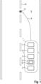
- Fig. 1 shows a schematic top view according to an embodiment of a motor vehicle 10.
- the motor vehicle 10 comprises at least an assistance system 2 for determining a warning vibration signal 18 ( Fig. 4 ) on a steering wheel of the motor vehicle 1.
- the assistance system 2 therefore comprises at least one capturing device 4 and one electronic computing device 5, wherein the electronic computing device 5 comprises at least one artificial intelligence 6.
- the assistance system 2 is configured as a so-called lane support system (LSS). Therefore, the assistance system 2 may comprise a further capturing device 7, for example, a radar sensor or a camera, which captures surroundings 8 of the motor vehicle 1.
- the assistance system 2 may be configured for determining a future trajectory 9. According to the shown embodiment, the future trajectory 9 may cross a lane 10 in the future. Therefore, a vibration signal, in particular a warning vibration signal 18, may be generated for warning a user of the motor vehicle 1.
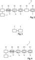
- Fig. 2 shows a schematic flow chart according to an embodiment of a method for generating training data 11 for training the artificial intelligence 6 for determining a warning vibration signal 18 on the steering wheel 3 of the motor vehicle 1. Therefore, a test system 12 may be provided.
- the test system 12 may use the same capturing device 4 as well as the same electronic computing device 5 as the assistance system 2, for generating the training data 11.
- the test system 12 may comprise a separate electronic computing device as well as a separate capturing device.
- a vibration on the steering wheel 3 is captured by the capturing device 4.
- a vibration signal 13 is generated in a second step S2 depending on the captured vibration by the electronic computing device 5.
- a scalogram 14 of the vibration signal 13 is generated by the electronic computing device 5.
- a fourth step S4 labeling the warning vibration signal 18 in the scalogram 14 is performed by using a classification algorithm 15 for the warning vibration signal by the electronic computing device 5.
- the labeled warning vibration signal 18 is extracted from the vibration signal 13 by the electronic computing device 5, and the training data 11 is generated depending on the extracted warning vibration signal 18 by the electronic computing device 5.
- the classification algorithm 15 may be provided as a one class classification algorithm 15.
- the vibration is divided in a time frame, and the vibration signal 13 is generated depending on a vibration in a time frame.
- training data 11 may be generated for an autoencoder as the artificial intelligence 6.
- Fig. 3 shows another flow chart according to an embodiment of a method for training an artificial intelligence 6 for determining a warning vibration signal 18 on the steering wheel 3 of the motor vehicle 1 by using the training data 11.
- the training data 11 are an input for the artificial intelligence 6.
- autoencoders are used as a special type of the unsupervised networks which can operate perfectly as one class classificators. They could not be trained to produce a class or digit as an output, but they can reproduce the inputs that were fed into the network.
- Fig. 4 another flow chart according to the embodiment for a method for determining a warning vibration signal 18 on the steering wheel 3 by the assistance system 2.
- a vibration on the steering wheel 3 is captured by the capturing device 4.
- the vibration signal 13 is generated depending on the captured vibration by the electronic computing device 5 of the assistance system 2.
- the scalogram 14 of the vibration signal 13 is generated by the electronic computing device 5.
- a warning vibration signal 18 is determined in the vibration signal 13 by using the artificial intelligence 6.
- a time frame 16 between a lane event 17 ( Fig. 1 ) and the determined warning vibration signal 18 is determined by the electronic computing device 5.
- the lane event 17 may be a potential lane crossing of the motor vehicle 1, as shown in Fig. 1 in the future.
- the method is going to be used that the recorded signal of the steering column moments is an input of the given to the algorithm and the algorithm does the steps of windowing, creating scalograms 14 from each timing window, setting the sequence of the scalograms 14 in temporal order, and finding the reconstruction error for each scalogram 14 through the autoencoder and assigning the value of reconstruction error to each scalogram 14.
- the scalograms 14 and their corresponding reconstruction error may be, for example, a table of two columns, in the first column the scalograms 14 are saved in temporal order, and in the second column, the respective reconstruction error of each scalogram 14 is calculated. Afterwards, the algorithm goes through the second column, where the reconstruction errors are saved in temporal order and will search for the spots where three or more scalograms 14 in a row are labeled with 1. Each set of those scalograms 14 would present on the time interval containing the event. For specifying the start and end point of the time interval, where the event was presented, the starting point of the initial window and the end point of the last window with the label 1 will be taken.
Landscapes
- Engineering & Computer Science (AREA)
- Automation & Control Theory (AREA)
- Transportation (AREA)
- Mechanical Engineering (AREA)
- Physics & Mathematics (AREA)
- General Physics & Mathematics (AREA)
- Human Computer Interaction (AREA)
- Theoretical Computer Science (AREA)
- Biomedical Technology (AREA)
- General Health & Medical Sciences (AREA)
- Life Sciences & Earth Sciences (AREA)
- Biophysics (AREA)
- Computational Linguistics (AREA)
- Data Mining & Analysis (AREA)
- Evolutionary Computation (AREA)
- Artificial Intelligence (AREA)
- Molecular Biology (AREA)
- Computing Systems (AREA)
- General Engineering & Computer Science (AREA)
- Mathematical Physics (AREA)
- Software Systems (AREA)
- Health & Medical Sciences (AREA)
- Traffic Control Systems (AREA)
Priority Applications (1)
| Application Number | Priority Date | Filing Date | Title |
|---|---|---|---|
| EP22211539.6A EP4382884A1 (de) | 2022-12-05 | 2022-12-05 | Verfahren zum erzeugen von trainingsdaten zum trainieren einer künstlichen intelligenz, verfahren zum warnen, computerprogrammprodukt, testsystem und assistenzsystem |
Applications Claiming Priority (1)
| Application Number | Priority Date | Filing Date | Title |
|---|---|---|---|
| EP22211539.6A EP4382884A1 (de) | 2022-12-05 | 2022-12-05 | Verfahren zum erzeugen von trainingsdaten zum trainieren einer künstlichen intelligenz, verfahren zum warnen, computerprogrammprodukt, testsystem und assistenzsystem |
Publications (1)
| Publication Number | Publication Date |
|---|---|
| EP4382884A1 true EP4382884A1 (de) | 2024-06-12 |
Family
ID=84488845
Family Applications (1)
| Application Number | Title | Priority Date | Filing Date |
|---|---|---|---|
| EP22211539.6A Pending EP4382884A1 (de) | 2022-12-05 | 2022-12-05 | Verfahren zum erzeugen von trainingsdaten zum trainieren einer künstlichen intelligenz, verfahren zum warnen, computerprogrammprodukt, testsystem und assistenzsystem |
Country Status (1)
| Country | Link |
|---|---|
| EP (1) | EP4382884A1 (de) |
Citations (2)
| Publication number | Priority date | Publication date | Assignee | Title |
|---|---|---|---|---|
| US20160221575A1 (en) | 2013-09-05 | 2016-08-04 | Avl List Gmbh | Method and device for optimizing driver assistance systems |
| US20200346656A1 (en) | 2017-07-14 | 2020-11-05 | Ccc Information Services Inc. | Driver Assist Design Analysis System |
-
2022
- 2022-12-05 EP EP22211539.6A patent/EP4382884A1/de active Pending
Patent Citations (2)
| Publication number | Priority date | Publication date | Assignee | Title |
|---|---|---|---|---|
| US20160221575A1 (en) | 2013-09-05 | 2016-08-04 | Avl List Gmbh | Method and device for optimizing driver assistance systems |
| US20200346656A1 (en) | 2017-07-14 | 2020-11-05 | Ccc Information Services Inc. | Driver Assist Design Analysis System |
Non-Patent Citations (1)
| Title |
|---|
| RE FABRIZIO ET AL: "Testing the Robustness of Commercial Lane Departure Warning Systems", TRANSPORTATION RESEARCH RECORD., vol. 2675, no. 12, 5 December 2021 (2021-12-05), US, pages 385 - 400, XP093045938, ISSN: 0361-1981, Retrieved from the Internet <URL:http://journals.sagepub.com/doi/full-xml/10.1177/03611981211029646> [retrieved on 20230510], DOI: 10.1177/03611981211029646 * |
Similar Documents
| Publication | Publication Date | Title |
|---|---|---|
| EP3693823B1 (de) | Vorrichtung und verfahren zur detektion eines fehlers | |
| Bello-Salau et al. | New road anomaly detection and characterization algorithm for autonomous vehicles | |
| CN113805834B (zh) | 一种汽车智能座舱测试方法、系统、装置和存储介质 | |
| KR102791070B1 (ko) | 딥러닝 기반 교량 신축 이음 부위의 손상 탐지 방법 및 이를 수행하는 프로그램을 기록한 기록매체 | |
| CN114140025A (zh) | 面向多模态数据的车险欺诈行为预测系统、方法和装置 | |
| CN115311246A (zh) | 一种基于大数据的桥梁安全管理方法和系统 | |
| US20250304128A1 (en) | Unsupervised Learning-based Fault Diagnosis Method and System for Detecting Wheel Out of Round in Rail Transit | |
| CN112784817B (zh) | 车辆所在车道检测方法、装置、设备及存储介质 | |
| US20230237584A1 (en) | Systems and methods for evaluating vehicle insurance claims | |
| EP4382884A1 (de) | Verfahren zum erzeugen von trainingsdaten zum trainieren einer künstlichen intelligenz, verfahren zum warnen, computerprogrammprodukt, testsystem und assistenzsystem | |
| CN116756680A (zh) | 事故的检测方法、装置、电子设备和可读存储介质 | |
| EP4468174A1 (de) | Verfahren zum erzeugen von trainingsdaten zum trainieren einer künstlichen intelligenz, verfahren zum trainieren einer künstlichen intelligenz | |
| CN118549532B (zh) | 一种公路桥梁安全性监测方法及装置 | |
| KR102907411B1 (ko) | 음향 분석 기능이 향상된 중고차 ai 성능점검 시스템 및 처리방법과 이를 위한 오디오 영상 시각화 장치 | |
| CN119169557A (zh) | 车辆故障的自动确定方法、装置及计算机可读存储介质 | |
| Medghalchi et al. | A machine learning-based algorithm for automated detection of frequency-based events in recorded time series of sensor data | |
| Deuschle et al. | Robust sensor spike detection method based on dynamic time warping | |
| JP2002042113A (ja) | 車両通行量測定システム | |
| Sohn et al. | A STATISTICAL PATTERN RECOGNITION | |
| CN119048750B (zh) | 一种边坡柔性防护系统耗能器工作状态无接触智能化检测方法 | |
| CN111610205A (zh) | 一种金属零部件x光图像缺陷检测装置 | |
| CN119091158A (zh) | 一种基于卷积神经网络的车辆故障预警方法及系统 | |
| Choudhury | AProcess FOR COMPLETE AUTONOMOUS SOFTWARE DISPLAY VALIDATION AND TESTING (USING A CAR-CLUSTER) | |
| Bokaeian et al. | Bridge weigh-in-motion event detection using wavelet scattering features and unsupervised learning | |
| CN121095900A (zh) | 识别路面损坏地段的方法、装置、设备及存储介质 |
Legal Events
| Date | Code | Title | Description |
|---|---|---|---|
| PUAI | Public reference made under article 153(3) epc to a published international application that has entered the european phase |
Free format text: ORIGINAL CODE: 0009012 |
|
| STAA | Information on the status of an ep patent application or granted ep patent |
Free format text: STATUS: THE APPLICATION HAS BEEN PUBLISHED |
|
| AK | Designated contracting states |
Kind code of ref document: A1 Designated state(s): AL AT BE BG CH CY CZ DE DK EE ES FI FR GB GR HR HU IE IS IT LI LT LU LV MC ME MK MT NL NO PL PT RO RS SE SI SK SM TR |
|
| STAA | Information on the status of an ep patent application or granted ep patent |
Free format text: STATUS: REQUEST FOR EXAMINATION WAS MADE |
|
| 17P | Request for examination filed |
Effective date: 20241212 |