EP4382818A1 - Storage water heater equipped with at least one auxiliary heater and a by-pass duct - Google Patents
Storage water heater equipped with at least one auxiliary heater and a by-pass duct Download PDFInfo
- Publication number
- EP4382818A1 EP4382818A1 EP23212531.0A EP23212531A EP4382818A1 EP 4382818 A1 EP4382818 A1 EP 4382818A1 EP 23212531 A EP23212531 A EP 23212531A EP 4382818 A1 EP4382818 A1 EP 4382818A1
- Authority
- EP
- European Patent Office
- Prior art keywords
- heater
- heating device
- water heater
- temperature
- duct
- Prior art date
- Legal status (The legal status is an assumption and is not a legal conclusion. Google has not performed a legal analysis and makes no representation as to the accuracy of the status listed.)
- Granted
Links
Images





Classifications
-
- F—MECHANICAL ENGINEERING; LIGHTING; HEATING; WEAPONS; BLASTING
- F24—HEATING; RANGES; VENTILATING
- F24H—FLUID HEATERS, e.g. WATER OR AIR HEATERS, HAVING HEAT-GENERATING MEANS, e.g. HEAT PUMPS, IN GENERAL
- F24H9/00—Details
- F24H9/12—Arrangements for connecting heaters to circulation pipes
- F24H9/13—Arrangements for connecting heaters to circulation pipes for water heaters
- F24H9/133—Storage heaters
- F24H9/136—Arrangement of inlet valves used therewith
-
- F—MECHANICAL ENGINEERING; LIGHTING; HEATING; WEAPONS; BLASTING
- F24—HEATING; RANGES; VENTILATING
- F24H—FLUID HEATERS, e.g. WATER OR AIR HEATERS, HAVING HEAT-GENERATING MEANS, e.g. HEAT PUMPS, IN GENERAL
- F24H1/00—Water heaters, e.g. boilers, continuous-flow heaters or water-storage heaters
- F24H1/18—Water-storage heaters
- F24H1/185—Water-storage heaters using electric energy supply
-
- F—MECHANICAL ENGINEERING; LIGHTING; HEATING; WEAPONS; BLASTING
- F24—HEATING; RANGES; VENTILATING
- F24D—DOMESTIC- OR SPACE-HEATING SYSTEMS, e.g. CENTRAL HEATING SYSTEMS; DOMESTIC HOT-WATER SUPPLY SYSTEMS; ELEMENTS OR COMPONENTS THEREFOR
- F24D17/00—Domestic hot-water supply systems
- F24D17/0036—Domestic hot-water supply systems with combination of different kinds of heating means
- F24D17/0063—Domestic hot-water supply systems with combination of different kinds of heating means solar energy and conventional heaters
-
- F—MECHANICAL ENGINEERING; LIGHTING; HEATING; WEAPONS; BLASTING
- F24—HEATING; RANGES; VENTILATING
- F24D—DOMESTIC- OR SPACE-HEATING SYSTEMS, e.g. CENTRAL HEATING SYSTEMS; DOMESTIC HOT-WATER SUPPLY SYSTEMS; ELEMENTS OR COMPONENTS THEREFOR
- F24D17/00—Domestic hot-water supply systems
- F24D17/0036—Domestic hot-water supply systems with combination of different kinds of heating means
- F24D17/0063—Domestic hot-water supply systems with combination of different kinds of heating means solar energy and conventional heaters
- F24D17/0068—Domestic hot-water supply systems with combination of different kinds of heating means solar energy and conventional heaters with accumulation of the heated water
-
- F—MECHANICAL ENGINEERING; LIGHTING; HEATING; WEAPONS; BLASTING
- F24—HEATING; RANGES; VENTILATING
- F24D—DOMESTIC- OR SPACE-HEATING SYSTEMS, e.g. CENTRAL HEATING SYSTEMS; DOMESTIC HOT-WATER SUPPLY SYSTEMS; ELEMENTS OR COMPONENTS THEREFOR
- F24D17/00—Domestic hot-water supply systems
- F24D17/02—Domestic hot-water supply systems using heat pumps
-
- F—MECHANICAL ENGINEERING; LIGHTING; HEATING; WEAPONS; BLASTING
- F24—HEATING; RANGES; VENTILATING
- F24D—DOMESTIC- OR SPACE-HEATING SYSTEMS, e.g. CENTRAL HEATING SYSTEMS; DOMESTIC HOT-WATER SUPPLY SYSTEMS; ELEMENTS OR COMPONENTS THEREFOR
- F24D19/00—Details
- F24D19/10—Arrangement or mounting of control or safety devices
- F24D19/1006—Arrangement or mounting of control or safety devices for water heating systems
- F24D19/1051—Arrangement or mounting of control or safety devices for water heating systems for domestic hot water
-
- F—MECHANICAL ENGINEERING; LIGHTING; HEATING; WEAPONS; BLASTING
- F24—HEATING; RANGES; VENTILATING
- F24D—DOMESTIC- OR SPACE-HEATING SYSTEMS, e.g. CENTRAL HEATING SYSTEMS; DOMESTIC HOT-WATER SUPPLY SYSTEMS; ELEMENTS OR COMPONENTS THEREFOR
- F24D19/00—Details
- F24D19/10—Arrangement or mounting of control or safety devices
- F24D19/1006—Arrangement or mounting of control or safety devices for water heating systems
- F24D19/1051—Arrangement or mounting of control or safety devices for water heating systems for domestic hot water
- F24D19/1054—Arrangement or mounting of control or safety devices for water heating systems for domestic hot water the system uses a heat pump
-
- F—MECHANICAL ENGINEERING; LIGHTING; HEATING; WEAPONS; BLASTING
- F24—HEATING; RANGES; VENTILATING
- F24D—DOMESTIC- OR SPACE-HEATING SYSTEMS, e.g. CENTRAL HEATING SYSTEMS; DOMESTIC HOT-WATER SUPPLY SYSTEMS; ELEMENTS OR COMPONENTS THEREFOR
- F24D19/00—Details
- F24D19/10—Arrangement or mounting of control or safety devices
- F24D19/1006—Arrangement or mounting of control or safety devices for water heating systems
- F24D19/1051—Arrangement or mounting of control or safety devices for water heating systems for domestic hot water
- F24D19/1057—Arrangement or mounting of control or safety devices for water heating systems for domestic hot water the system uses solar energy
-
- F—MECHANICAL ENGINEERING; LIGHTING; HEATING; WEAPONS; BLASTING
- F24—HEATING; RANGES; VENTILATING
- F24H—FLUID HEATERS, e.g. WATER OR AIR HEATERS, HAVING HEAT-GENERATING MEANS, e.g. HEAT PUMPS, IN GENERAL
- F24H1/00—Water heaters, e.g. boilers, continuous-flow heaters or water-storage heaters
- F24H1/18—Water-storage heaters
- F24H1/186—Water-storage heaters using fluid fuel
-
- F—MECHANICAL ENGINEERING; LIGHTING; HEATING; WEAPONS; BLASTING
- F24—HEATING; RANGES; VENTILATING
- F24H—FLUID HEATERS, e.g. WATER OR AIR HEATERS, HAVING HEAT-GENERATING MEANS, e.g. HEAT PUMPS, IN GENERAL
- F24H15/00—Control of fluid heaters
- F24H15/10—Control of fluid heaters characterised by the purpose of the control
- F24H15/174—Supplying heated water with desired temperature or desired range of temperature
-
- F—MECHANICAL ENGINEERING; LIGHTING; HEATING; WEAPONS; BLASTING
- F24—HEATING; RANGES; VENTILATING
- F24H—FLUID HEATERS, e.g. WATER OR AIR HEATERS, HAVING HEAT-GENERATING MEANS, e.g. HEAT PUMPS, IN GENERAL
- F24H15/00—Control of fluid heaters
- F24H15/20—Control of fluid heaters characterised by control inputs
- F24H15/212—Temperature of the water
- F24H15/215—Temperature of the water before heating
-
- F—MECHANICAL ENGINEERING; LIGHTING; HEATING; WEAPONS; BLASTING
- F24—HEATING; RANGES; VENTILATING
- F24H—FLUID HEATERS, e.g. WATER OR AIR HEATERS, HAVING HEAT-GENERATING MEANS, e.g. HEAT PUMPS, IN GENERAL
- F24H15/00—Control of fluid heaters
- F24H15/20—Control of fluid heaters characterised by control inputs
- F24H15/212—Temperature of the water
- F24H15/219—Temperature of the water after heating
-
- F—MECHANICAL ENGINEERING; LIGHTING; HEATING; WEAPONS; BLASTING
- F24—HEATING; RANGES; VENTILATING
- F24H—FLUID HEATERS, e.g. WATER OR AIR HEATERS, HAVING HEAT-GENERATING MEANS, e.g. HEAT PUMPS, IN GENERAL
- F24H15/00—Control of fluid heaters
- F24H15/20—Control of fluid heaters characterised by control inputs
- F24H15/212—Temperature of the water
- F24H15/223—Temperature of the water in the water storage tank
- F24H15/225—Temperature of the water in the water storage tank at different heights of the tank
-
- F—MECHANICAL ENGINEERING; LIGHTING; HEATING; WEAPONS; BLASTING
- F24—HEATING; RANGES; VENTILATING
- F24H—FLUID HEATERS, e.g. WATER OR AIR HEATERS, HAVING HEAT-GENERATING MEANS, e.g. HEAT PUMPS, IN GENERAL
- F24H15/00—Control of fluid heaters
- F24H15/30—Control of fluid heaters characterised by control outputs; characterised by the components to be controlled
- F24H15/305—Control of valves
- F24H15/31—Control of valves of valves having only one inlet port and one outlet port, e.g. flow rate regulating valves
-
- F—MECHANICAL ENGINEERING; LIGHTING; HEATING; WEAPONS; BLASTING
- F24—HEATING; RANGES; VENTILATING
- F24H—FLUID HEATERS, e.g. WATER OR AIR HEATERS, HAVING HEAT-GENERATING MEANS, e.g. HEAT PUMPS, IN GENERAL
- F24H15/00—Control of fluid heaters
- F24H15/30—Control of fluid heaters characterised by control outputs; characterised by the components to be controlled
- F24H15/335—Control of pumps, e.g. on-off control
-
- F—MECHANICAL ENGINEERING; LIGHTING; HEATING; WEAPONS; BLASTING
- F24—HEATING; RANGES; VENTILATING
- F24H—FLUID HEATERS, e.g. WATER OR AIR HEATERS, HAVING HEAT-GENERATING MEANS, e.g. HEAT PUMPS, IN GENERAL
- F24H15/00—Control of fluid heaters
- F24H15/30—Control of fluid heaters characterised by control outputs; characterised by the components to be controlled
- F24H15/355—Control of heat-generating means in heaters
- F24H15/37—Control of heat-generating means in heaters of electric heaters
-
- F—MECHANICAL ENGINEERING; LIGHTING; HEATING; WEAPONS; BLASTING
- F24—HEATING; RANGES; VENTILATING
- F24H—FLUID HEATERS, e.g. WATER OR AIR HEATERS, HAVING HEAT-GENERATING MEANS, e.g. HEAT PUMPS, IN GENERAL
- F24H15/00—Control of fluid heaters
- F24H15/30—Control of fluid heaters characterised by control outputs; characterised by the components to be controlled
- F24H15/375—Control of heat pumps
-
- F—MECHANICAL ENGINEERING; LIGHTING; HEATING; WEAPONS; BLASTING
- F24—HEATING; RANGES; VENTILATING
- F24H—FLUID HEATERS, e.g. WATER OR AIR HEATERS, HAVING HEAT-GENERATING MEANS, e.g. HEAT PUMPS, IN GENERAL
- F24H15/00—Control of fluid heaters
- F24H15/40—Control of fluid heaters characterised by the type of controllers
- F24H15/414—Control of fluid heaters characterised by the type of controllers using electronic processing, e.g. computer-based
- F24H15/421—Control of fluid heaters characterised by the type of controllers using electronic processing, e.g. computer-based using pre-stored data
- F24H15/429—Control of fluid heaters characterised by the type of controllers using electronic processing, e.g. computer-based using pre-stored data for selecting operation modes
-
- F—MECHANICAL ENGINEERING; LIGHTING; HEATING; WEAPONS; BLASTING
- F24—HEATING; RANGES; VENTILATING
- F24H—FLUID HEATERS, e.g. WATER OR AIR HEATERS, HAVING HEAT-GENERATING MEANS, e.g. HEAT PUMPS, IN GENERAL
- F24H4/00—Fluid heaters characterised by the use of heat pumps
- F24H4/02—Water heaters
-
- F—MECHANICAL ENGINEERING; LIGHTING; HEATING; WEAPONS; BLASTING
- F24—HEATING; RANGES; VENTILATING
- F24H—FLUID HEATERS, e.g. WATER OR AIR HEATERS, HAVING HEAT-GENERATING MEANS, e.g. HEAT PUMPS, IN GENERAL
- F24H4/00—Fluid heaters characterised by the use of heat pumps
- F24H4/02—Water heaters
- F24H4/04—Storage heaters
-
- F—MECHANICAL ENGINEERING; LIGHTING; HEATING; WEAPONS; BLASTING
- F24—HEATING; RANGES; VENTILATING
- F24H—FLUID HEATERS, e.g. WATER OR AIR HEATERS, HAVING HEAT-GENERATING MEANS, e.g. HEAT PUMPS, IN GENERAL
- F24H9/00—Details
- F24H9/0005—Details for water heaters
-
- F—MECHANICAL ENGINEERING; LIGHTING; HEATING; WEAPONS; BLASTING
- F24—HEATING; RANGES; VENTILATING
- F24H—FLUID HEATERS, e.g. WATER OR AIR HEATERS, HAVING HEAT-GENERATING MEANS, e.g. HEAT PUMPS, IN GENERAL
- F24H9/00—Details
- F24H9/18—Arrangement or mounting of grates or heating means
- F24H9/1809—Arrangement or mounting of grates or heating means for water heaters
- F24H9/1818—Arrangement or mounting of electric heating means
-
- F—MECHANICAL ENGINEERING; LIGHTING; HEATING; WEAPONS; BLASTING
- F24—HEATING; RANGES; VENTILATING
- F24H—FLUID HEATERS, e.g. WATER OR AIR HEATERS, HAVING HEAT-GENERATING MEANS, e.g. HEAT PUMPS, IN GENERAL
- F24H9/00—Details
- F24H9/18—Arrangement or mounting of grates or heating means
- F24H9/1809—Arrangement or mounting of grates or heating means for water heaters
- F24H9/1832—Arrangement or mounting of combustion heating means, e.g. grates or burners
- F24H9/1836—Arrangement or mounting of combustion heating means, e.g. grates or burners using fluid fuel
-
- F—MECHANICAL ENGINEERING; LIGHTING; HEATING; WEAPONS; BLASTING
- F24—HEATING; RANGES; VENTILATING
- F24H—FLUID HEATERS, e.g. WATER OR AIR HEATERS, HAVING HEAT-GENERATING MEANS, e.g. HEAT PUMPS, IN GENERAL
- F24H9/00—Details
- F24H9/20—Arrangement or mounting of control or safety devices
- F24H9/2007—Arrangement or mounting of control or safety devices for water heaters
- F24H9/2014—Arrangement or mounting of control or safety devices for water heaters using electrical energy supply
- F24H9/2021—Storage heaters
-
- F—MECHANICAL ENGINEERING; LIGHTING; HEATING; WEAPONS; BLASTING
- F24—HEATING; RANGES; VENTILATING
- F24S—SOLAR HEAT COLLECTORS; SOLAR HEAT SYSTEMS
- F24S20/00—Solar heat collectors specially adapted for particular uses or environments
- F24S20/40—Solar heat collectors combined with other heat sources, e.g. using electrical heating or heat from ambient air
-
- F—MECHANICAL ENGINEERING; LIGHTING; HEATING; WEAPONS; BLASTING
- F24—HEATING; RANGES; VENTILATING
- F24D—DOMESTIC- OR SPACE-HEATING SYSTEMS, e.g. CENTRAL HEATING SYSTEMS; DOMESTIC HOT-WATER SUPPLY SYSTEMS; ELEMENTS OR COMPONENTS THEREFOR
- F24D2200/00—Heat sources or energy sources
- F24D2200/11—Geothermal energy
-
- F—MECHANICAL ENGINEERING; LIGHTING; HEATING; WEAPONS; BLASTING
- F24—HEATING; RANGES; VENTILATING
- F24D—DOMESTIC- OR SPACE-HEATING SYSTEMS, e.g. CENTRAL HEATING SYSTEMS; DOMESTIC HOT-WATER SUPPLY SYSTEMS; ELEMENTS OR COMPONENTS THEREFOR
- F24D2200/00—Heat sources or energy sources
- F24D2200/12—Heat pump
-
- F—MECHANICAL ENGINEERING; LIGHTING; HEATING; WEAPONS; BLASTING
- F24—HEATING; RANGES; VENTILATING
- F24D—DOMESTIC- OR SPACE-HEATING SYSTEMS, e.g. CENTRAL HEATING SYSTEMS; DOMESTIC HOT-WATER SUPPLY SYSTEMS; ELEMENTS OR COMPONENTS THEREFOR
- F24D2200/00—Heat sources or energy sources
- F24D2200/14—Solar energy
-
- F—MECHANICAL ENGINEERING; LIGHTING; HEATING; WEAPONS; BLASTING
- F24—HEATING; RANGES; VENTILATING
- F24D—DOMESTIC- OR SPACE-HEATING SYSTEMS, e.g. CENTRAL HEATING SYSTEMS; DOMESTIC HOT-WATER SUPPLY SYSTEMS; ELEMENTS OR COMPONENTS THEREFOR
- F24D2220/00—Components of central heating installations excluding heat sources
- F24D2220/04—Sensors
- F24D2220/042—Temperature sensors
-
- F—MECHANICAL ENGINEERING; LIGHTING; HEATING; WEAPONS; BLASTING
- F24—HEATING; RANGES; VENTILATING
- F24D—DOMESTIC- OR SPACE-HEATING SYSTEMS, e.g. CENTRAL HEATING SYSTEMS; DOMESTIC HOT-WATER SUPPLY SYSTEMS; ELEMENTS OR COMPONENTS THEREFOR
- F24D2220/00—Components of central heating installations excluding heat sources
- F24D2220/04—Sensors
- F24D2220/044—Flow sensors
Definitions
- the object of the present invention is a storage water heater or the like, preferably used for the production of domestic hot water.
- the present invention refers to a storage water heater provided with at least a main heater and at least a additional/auxiliary heater.
- the present invention refers to a storage water heater heated by at least a main heater and provided with at least a first and/or second additional/auxiliary heater.
- a further object of the present invention is a management method of a storage water heater and of the heating elements thereof.
- Storage water heaters are currently known provided with a main and additional heater arranged within the storage tank of the water to be heated.
- said additional heater comprises one or more electric resistances which, by conduction, heat the water wherein they are immersed.
- the main one is linked to the fact that the contact with water causes the electrical resistance to have a gradual deterioration and loss of efficiency due to the formation of limescale or the like.
- the electrical resistance requires maintenance or a replacement thereof, increasing the management costs of the same water heater.
- Another problem of the current water heaters concerns the overall dimensions and size thereof strictly related to the shape and capacity (volume) of the tank, but also to the overall dimensions of the heating elements provided for by the same water heater.
- the heat pumps which are more and more applied in the sector of the storage water heaters, have significant overall dimensions due to the presence of heat exchangers (evaporator/condenser) which require certain heat exchange surfaces and the presence of essential components, such as for example compressors or others, in order to carry out their function.
- heat exchangers evaporator/condenser
- essential components such as for example compressors or others
- the aim of the present invention is to obviate such kind of drawbacks by providing a storage water heater or the like, preferably for the production of domestic hot water, able to keep low the overall dimensions.
- a further object of the present invention is to provide a storage water heater or the like provided with at least a main heater and at least a additional/auxiliary heater.
- a further object of the present invention is to provide a management method of a storage water heater and of the heating elements thereof.
- storage water heater is herein to be understood as any device capable of heating water in a storage tank, in particular domestic hot water for hygienic uses, until reaching a certain temperature herein defined as the set-point temperature T. set.
- 1 indicates, as a whole, the storage water heater 1 according to the present invention, hereinafter referred to as only water heater 1, for clarity of description.
- said water heater 1 may comprise at least a heating device, at least a storage tank 10 wherein water is stored and heated, at least a control and management unit capable of controlling said at least a heating device, at least a inlet duct 11 through which water may be introduced into the tank 10, at least a outlet duct 12 through which water may be sent/withdrawn from the tank 10, said inlet ducts 11 and 12 being in fluid communication with said tank 10.
- the heating device may be of the electric type, i.e. comprising at least a electric device such as for example electric resistances or the like, or of the heat pump type, a variant illustrated by way of a non-limiting example in the accompanying figures, solar energy, gas, geothermal or the like or possible combinations thereof.
- a electric device such as for example electric resistances or the like
- the heat pump type a variant illustrated by way of a non-limiting example in the accompanying figures, solar energy, gas, geothermal or the like or possible combinations thereof.
- solar energy, gas, geothermal or the like a variant illustrated by way of a non-limiting example in the accompanying figures, solar energy, gas, geothermal or the like or possible combinations thereof.
- the water inside the storage tank has a stratification according to the temperature, said stratification being due to the heating process caused by the heating elements and by the density of the water. In fact, the hottest water tends to migrate and settle in the top part of the tank, while the colder water tends to settle in the lower
- the outlet section 110 of the inlet duct 11 is preferably positioned in the proximity of the lower zone of the said tank 10, while the inlet section 120 of the outlet duct 12 is preferably positioned in the proximity of the median or, even more preferably, top zone of the said tank 10.
- such arrangement determines a water make-up, generally from the water network, in the lower area of the tank 10 and a withdrawal of hot water in the upper zone thereof, thus keeping the stratification of the water based on the temperature thereof and essentially guaranteeing the withdrawal and supply of hot water.
- said water heater 1 comprises at least two heating devices, of which preferably at least a main and at least a auxiliary.
- main heating device refers to as a device which is designed to heat water in normal/standard conditions
- auxiliary is to be understood as a device designed to heat water in particular conditions, for example when it is preferable to have a heat source in addition to the main one.
- said second device 4 may be installed along the inlet duct 11, so as to act as a pre-heater, i.e., be able to heat the make-up water entering the tank 10, hereinafter referred to as pre-heater 4.
- said water heater 1 may further comprise at least a third heating device 5, herein identified as "auxiliary", which may comprise heaters, preferably of the instantaneous type, comprising, for example, electric heaters, electric resistances or the like.
- Said third auxiliary device 5 is preferably installed along the outlet duct 12 so as to be able to act as a post-heater, i.e. be able to heat the water supplied exiting the tank 10, hereinafter referred to as post-heater 5, and may be arranged externally to said storage tank 10.
- said water heater 1 simultaneously comprises at least a pre-heater 4 and at least a post-heater 5.
- an auxiliary device both when it acts as a pre-heater 4 and when it acts as a post-heater 5, which may be equipped with power regulating means which allow the energy supply, provided by the auxiliary device to be managed in relation to the comparison between the energy contents: of the storage water and of the recirculation water and/or of the storage water and of the make-up and/or of the storage water and of the water supplied by the water heater 1.
- said second device 4 is installed upstream of the outlet section 110 of the inlet duct 11, while said third device 5 is installed downstream of the inlet section 120 of the outlet duct 12.
- the arrangement of said second 4 and third 5 heating device which, as said, are preferably external to the tank 10, allows for a convenient inspection and a possible easy replacement thereof.
- the inlet and outlet sections of the pre-heater 4 and of the post-heater 5, as well as the inlet 11 and outlet 12 ducts whereon they may be installed, are defined in relation to the normal operation of water heater 1, i.e. to the making up cold water and supplying hot water during a withdrawal in progress.
- the water heater 1 may further comprise:
- said sensors are suitably connected and communicating with said control unit.
- said flow sensor 60 may be installed along the inlet duct 11.
- the water heater 1 is characterised in that it comprises at least a by-pass duct 13, hereinafter referred to as only by-pass 13 for descriptive convenience, capable of deviating, entirely or partially, the water flow entering the tank 10 so as to guide and convey it in a zone of the tank 10 placed at a height higher than the outlet section 110 of the inlet duct 11 and at a height lower than the inlet section 120 of the outlet duct 12.
- said by-pass 13 guides and conveys the water entering the tank 10 in a zone of the said tank 10 comprised between the outlet section 110 of the inlet duct 11 and the inlet section 120 of the outlet duct 12.
- Said by-pass 13 substantially extends between the inlet duct 11, to which it is connected, and the zone of the tank 10 wherein it discharges/introduces the make-up water, said by-pass 13 being suitably shaped so as to comprise:
- the position of said outlet 131 inside the tank 10 may be varied as necessary so that said outlet 131 may be located in the upper or middle or lower zone of the said tank 10, substantially regulating, for example, the longitudinal extension of the said by -pass 13.
- the choice of the value of the distance h which may be made in the design or construction step, allows the entity of the volume " v " and therefore the quantity of water of the storage heated through the introduction of hot water heated by the pre-heater 4 to be determined/modified, according to the methods described shortly, and introduced via the by-pass 13.
- the make-up water, heated by the pre-heater 4 mixes, by heating it with a smaller quantity of water of the storage, making the water heater 1 more ready to satisfy the user.
- the by-pass 13 provides for at least a portion 134, herein referred to as outlet portion 134, which develops and is housed inside the tank 10 and whereon said at least a outlet 131 is obtained/placed.
- said outlet portion 134 is arranged substantially vertically inside the tank 10 and extends from a zone in the proximity of the bottom of the same tank 10, preferably engaging from the same bottom, to a median or upper zone of the tank 10 based on the longitudinal development thereof correlated to the established/chosen distance h.
- the by-pass 13 may be shaped substantially as an " L " or the like so as to be able to provide for:
- said pre-heater 4 is preferably positioned and installed along the inlet duct 11 (see for example the variants of Figures 1-3 , of Figures 5-7 , of Figures 9-10 ).
- the inlet 130 of the said by-pass 13 is placed along the inlet duct 11 downstream of the pre-heater 4, i.e. between the outlet 41 of the pre-heater 4 and the outlet section 110 of the inlet duct 11, preferably externally with respect to the tank 10.
- said pre-heater 4 is preferably positioned and installed along the by-pass duct 13 (see for example the variant of Figures 12-13 ), for example along said first portion 133.
- the inlet 130 of the said by-pass 13 is placed along the inlet duct 11 upstream of the inlet 40 of the pre-heater 4.
- said water heater 1 is further provided with at least a diverter means 8, hereinafter referred to as diverter valve 8, preferably of the electrically or mechanically controllable type, such as for example solenoid valves, motorised valves or the like, adapted to connect said by-pass duct 13, preferably the inlet 130 thereof, to said inlet duct 11.
- diverter valve 8 preferably of the electrically or mechanically controllable type, such as for example solenoid valves, motorised valves or the like, adapted to connect said by-pass duct 13, preferably the inlet 130 thereof, to said inlet duct 11.
- Said diverter valve 8 based on the type thereof, is capable of deviating the water entering the tank 10 either towards the by-pass 13 or towards the outlet section 110 or of possibly dividing it between both according to proportions set by the manufacturer and/or installer and/or user.
- said diverter valve 8 may be of the type:
- a controllable diverter valve 8 is placed along the inlet duct 11 in the section in which the by-pass 13 engages said inlet duct 11, said diverter valve 8 therefore acting as a union and connecting element among the parts and being also able to be installed externally to the tank 10.
- a diverter valve 8 capable of deviating, entirely or partially, the flow of make-up water entering the tank 10 so that it may be:
- the make-up water in the entirety or a portion thereof, may be advantageously heated or pre-heated through the pre-heater 4 according to methods described shortly.
- the entire make-up water is heated, regardless of whether it is introduced into the tank 10 via the inlet duct 11 only (mode i) or the by-pass 13 only (mode ii) or via both (mode iii), while in the variant of the case B only the make-up water which is diverted and passed through the by-pass 13 is heated.
- the water heater 1 is able to operate with the modes i), ii) and iii) reported above, regardless of whether the configuration thereof complies with the Case A or the Case B, said Cases A and B differing substantially only by the arrangement of the pre-heater 4.
- the water heater 1 is able to operate in mode i) and/or ii) even if it is equipped with an adjustable type diverter valve 8, as it is sufficient to completely close the valve 8 to implement mode i) and open it completely to implement mode ii).
- the achievement of the temperature Tc or Tset is quicker, at least for a portion v of the volume of the storage, since the pre-heated water, introduced at a distance h from the inlet section 120, tends to mix with the water of the volume v , said volume v being only a part/portion of the entire volume of the storage of the tank 10 ( Figure 3 or 7 ).
- the pre-heater 4 may heat the water substantially up to Tc, Tm or Tset or in general up to a temperature substantially similar to that of the water in the proximity of the zone of the storage into which it is introduced ( ⁇ b), so as to preserve and meet the temperature stratification of the storage.
- Such circumstance represents a hybrid/intermediate situation with respect to the methods i) and ii), the achievement of the temperature Tc or Tset being correlated to the adjustment degree of the diverter valve 8 and to the amount of make-up water which is introduced respectively via the by- pass 13 and the outlet section 110 ( Figure 10 ).
- the configuration of the Case B providing for heating only the make-up water which crosses the by-pass duct 13, allows the stratification of the tank 10, to be preserved more efficiently.
- the make-up water introduced by means of the outlet section 110 of the inlet duct 11 is not heated and considering that it has a temperature substantially equal to the temperature of the water network, it does not substantially alter the stratification of the storage.
- a possible management method of the water heater 1 shall now be described, by way of a non-limiting example, which may preferably be implemented via the control unit with which said water heater 1 is provided, said management method providing for different logics based on the fact that said water heater 1 comprises only the pre-heater 4 or both the pre-heater 4 and the post-heater 5 or is configured according to the Case A or the Case B or is equipped with an ON/OFF type or adjustable diverter valve.
- Said control unit is therefore capable of controlling and commanding the different components of the water heater 1, such as for example the diverter valve 8, and/or both the main and auxiliary heating devices.
- rectangle shape represents an action, for example the activation of a heating device
- diamond shape represents a control, for example a comparison among temperatures.
- Said management method is aimed at controlling/coordinating different components of the water heater 1 such as, for example, at least the different heating devices of the water heater 1, both said at least a main device 2 and one or more of said auxiliary devices 4, 5 and/or at least the diverter valve 8, based on the functions to be implemented, whether standard/normal or additional.
- the management method may consider different factors in order to implement such control/coordination, such as for example the presence/absence of a withdrawal, the number and/or type of said heating devices, and/or the set-point temperature Tset and/or the temperature Tc and/or the temperature of the storage water which may be possibly represented by one or more of the temperatures 3u and/or 3d and/or ⁇ b and or Tm and/or of the inlet 31 or outlet ⁇ o water temperature.
- Said management method is characterised in that it implements one or more supplementary heating functions, by one or more of said auxiliary devices 4, 5, of the water introduced and/or withdrawn from the storage, where the activation of at least one or more of said additional functions depending on at least:
- the non-activation or the deactivation of at least one or more of said additional functions may depend on at least the absence or end of a withdrawal.
- no withdrawal without any limiting intent, is to be referred to as both the lack of a withdrawal and the end thereof, these conditions corresponding to measurements of the flow sensor 60 substantially equal to zero.
- said additional functions may comprise, for example, at least the BOOST function, the POST-HEATING function or the like.
- Said management method of the water heater 1 may comprise at least the following phases.
- the first phase P1, S1 of the method according to the present invention provides for verifying, via the flow sensor 60, whether or not a hot water withdrawal is in progress and based on such condition, two different possible operating/management logics may be implemented, one of which is dedicated to the case of a withdrawal and the other to the case of absence of a withdrawal.
- said method provides for checking, through the phase P2, whether the BOOST function is selected or not.
- the BOOST function allows the make-up water to be heated, via at least said pre-heater 4, accelerating the heating of the storage and consequently reducing the time necessary to bring the storage substantially to Tset or to Tc.
- this allows the pre-heated water to be introduced into a zone in which the water of the storage, by virtue of the stratification phenomenon, has a higher temperature than the water of the storage in the proximity of the lower zone of the tank 10, speeding up the recovery of the storage at a temperature Tset or the attainment of the temperature Tc, in particular of the volume v.
- the make-up of the storage, via by-pass 13, of pre-heated water advantageously allows withdrawing hot or at least pre-heated water or in general with a temperature higher than the network temperature of the make-up water.
- the pre-heated water may be brought, via the pre-heater 4, to a temperature substantially equal to Tc, Tm or Tset or in general up to a temperature substantially similar to that of the water in the proximity of the storage zone wherein it is introduced, i.e. substantially equal to ⁇ b.
- the next phase P4 provides for monitoring the value of the temperature Tm by comparing it with Tset; the aim is not to allow the water of the storage to cool too much.
- Phase P40 is provided and implemented in the event that, as preferred, a hysteresis parameter X is subtracted from the temperature Tset in order to avoid frequent and subsequent re-ignitions of the main heating device 2.
- Said phase P40 provides for comparing Tm with Tset-X and following said comparison:
- the aim of the phase P43 is to check whether the main heating device 2 is switched on or not during the withdrawal.
- the management method provides for implementing phase P4 so as to monitor the value of the temperature Tm and compare it with Tset; the aim is not to allow the storage water to cool too much due to possible heat losses or the like.
- the auxiliary heating device is not active and the main heating device may possibly be activated following the comparison between Tm and Tset.
- the average temperature Tm may vary mainly due to heat losses or the like which may lead to a progressive decrease in the temperature Tm.
- the auxiliary heating devices are not active and the main heating device may possibly be activated following the comparison between Tm and Tset or between Tm and Tset-X according to the phases P40-P43 previously described.
- a possible management method of the water heater which may be equipped with at least the BOOST function and provided with both the pre-heater 4, located along the inlet duct 11 (Case A), and the post -heater 5 and with an on/off diverter means 8.
- said method provides for checking whether the outlet water To meets the comfort temperature Tc; the aim is that of checking whether the water supplied meets the parameters set by the manufacturer and/or installer and/or user.
- phase S2 Such check is carried out with the phase S2, through which there is checked whether the outlet temperature ⁇ o of the water heater 1 is higher than or equal to the comfort temperature Tc ( ⁇ o ⁇ Tc), where:
- Phase S21 provides for checking whether the BOOST function is selected or not. In fact, the method, following the control of the output temperature To, checks whether the BOOST function is set and selected or not.
- the BOOST function allows the make-up water to be heated, via at least said pre-heater 4, accelerating the heating of the storage and consequently reducing the time necessary to bring the storage substantially to Tset or Tc.
- phase S24 With the BOOST function selected and the pre-heater 4 active, implementing the phase S24 with which there is checked whether the temperature 3b is greater than the inlet one 31 is provided.
- the make-up of pre-heated water occurs via the outlet 131 of the by-pass 13, at a distance h from the inlet section 120 of the outlet duct 12.
- this allows the pre-heated water to be introduced into a zone in which the water of the storage, by virtue of the stratification phenomenon, has a higher temperature than the water of the storage in the proximity of the lower zone of the tank 10, speeding up the recovery of the storage at a temperature Tset or the attainment of the temperature Tc, in particular of the volume v.
- the post-heater 5 may intervene by providing the necessary heat.
- the next phase S4 provides for monitoring the value of the temperature Tm by comparing it with Tset; the aim is not to allow the water of the storage to cool too much.
- Phase S40 is provided and implemented in the event that, as preferred, a hysteresis parameter X is subtracted from the temperature Tset in order to avoid frequent and subsequent re-ignitions of the main heating device 2.
- phase S40 provides for comparing Tm with Tset-X and following said comparison:
- the aim of the phase S43 is to check whether the main heating device 2 is switched on or not during the withdrawal.
- the management method provides for implementing the phase S4 so as to monitor the temperature value Tm and compare it with Tset; the aim is not to allow the storage water to cool too much due to possible heat losses or the like.
- the auxiliary heating devices are not active and the main heating device may possibly be activated following the comparison between Tm and Tset, phase S4.
- Phase S40 is provided and implemented in the event that, as preferred, a hysteresis parameter X is subtracted from the temperature Tset, in order to avoid frequent and subsequent re-ignitions of the main heating device 2.
- phase S40 provides for comparing Tm with Tset-X and following said comparison:
- Phase S43 has the aim to check if the main heating device 2 is switched on or not.
- the temperature to which the storage should be heated is Tset and not Tset-X, therefore in the absence of a withdrawal:
- a possible management method of the water heater which may be equipped with at least the BOOST function and provided with both the pre-heater 4, located along the inlet duct 11 (Case A), and the post-heater 5 of an adjustable diverter means 8.
- phase of the method provided for such variant are substantially the same as described with reference to the possible management method applied to a water heater which may be equipped with at least the BOOST function and provided with both the pre-heater 4 and the post-heater 5 and a diverter means 8 on/off ( Figure 8 ).
- phase S25' relating to the operating logic in case of withdrawal.
- phase S24 is provided, with which there is checked whether the temperature 4b is higher than the inlet one 31.
- a possible management method of the water heater which may be equipped with at least the BOOST function and provided with both the pre-heater 4, located along the by-pass duct 13 (Case B), and the post-heater 5 of an adjustable diverter means 8.
- phase of the method provided for such variant are substantially the same as described with reference to the possible management method applied to a water heater which may be equipped with at least the BOOST function and provided with both the pre-heater 4, placed along the inlet duct 11, and the post-heater 5 and a diverter means 8 on/off ( Figure 8 ).
- phase S24 is provided, with which there is checked whether the temperature 4b is higher than the inlet one 31.
- make-up water is not heated and is introduced at network temperature into the tank 10 via the outlet section 110 of the inlet duct 11.
- the water heater according to the present invention thanks to the adoption of auxiliary heating devices, may install and use a smaller main heating device; that is further true in the case of the heat pumps.
- heat pumps of lower power have smaller heat exchange surfaces (evaporator/condenser) and the overall size of the same heat pump will be reduced.
- the electric heaters require, by their nature, reduced and compact overall dimensions and if they are used as auxiliary heating devices, the overall dimension of the water heater 1 is smaller than the overall dimension of a water heater of the same power which uses only one heat pump as a heating source.
Landscapes
- Engineering & Computer Science (AREA)
- Physics & Mathematics (AREA)
- General Engineering & Computer Science (AREA)
- Chemical & Material Sciences (AREA)
- Combustion & Propulsion (AREA)
- Mechanical Engineering (AREA)
- Thermal Sciences (AREA)
- Life Sciences & Earth Sciences (AREA)
- Sustainable Development (AREA)
- Sustainable Energy (AREA)
- Computer Hardware Design (AREA)
- Fluid Mechanics (AREA)
- Heat-Pump Type And Storage Water Heaters (AREA)
Abstract
characterised in that
it comprises at least two heating devices, of which at least a main heating device (2) and at least a second (4) auxiliary heating device adapted to act as a pre-heater (4),
and in that
said water heater (1) comprises a by-pass duct (13) capable of deviating, entirely or partially, the water flow entering said tank (10) so as to guide and convey it in a zone of the said tank (10) placed at a height higher than the outlet section (110) of the said inlet duct (11).
Description
- The object of the present invention is a storage water heater or the like, preferably used for the production of domestic hot water.
- More in detail, the present invention refers to a storage water heater provided with at least a main heater and at least a additional/auxiliary heater.
- Even more in detail, the present invention refers to a storage water heater heated by at least a main heater and provided with at least a first and/or second additional/auxiliary heater.
- A further object of the present invention is a management method of a storage water heater and of the heating elements thereof.
- Storage water heaters are currently known provided with a main and additional heater arranged within the storage tank of the water to be heated.
- Generally, said additional heater comprises one or more electric resistances which, by conduction, heat the water wherein they are immersed.
- Such type of water heater presents different drawbacks.
- The main one is linked to the fact that the contact with water causes the electrical resistance to have a gradual deterioration and loss of efficiency due to the formation of limescale or the like.
- During the use, therefore, the electrical resistance requires maintenance or a replacement thereof, increasing the management costs of the same water heater.
- Another problem of the current water heaters, concerns the overall dimensions and size thereof strictly related to the shape and capacity (volume) of the tank, but also to the overall dimensions of the heating elements provided for by the same water heater.
- Currently, water heaters that are compact and with small overall dimensions are preferred and such preference is not always met by the water heaters offered on the market.
- This is due to the type of heating elements installed by the water heater.
- For example, the heat pumps, which are more and more applied in the sector of the storage water heaters, have significant overall dimensions due to the presence of heat exchangers (evaporator/condenser) which require certain heat exchange surfaces and the presence of essential components, such as for example compressors or others, in order to carry out their function.
- The water heaters currently available, therefore, do not fully meet the needs of the market which requires small overall dimensions and low management/maintenance costs.
- The aim of the present invention is to obviate such kind of drawbacks by providing a storage water heater or the like, preferably for the production of domestic hot water, able to keep low the overall dimensions.
- A further object of the present invention, at least for one or more executive variants, is to provide a storage water heater or the like provided with at least a main heater and at least a additional/auxiliary heater.
- A further object of the present invention, at least for one or more executive variants, is to provide a management method of a storage water heater and of the heating elements thereof.
- These and other objects, which shall appear clear hereinafter, are achieved with a storage water heater or the like and relative management method, according to
claim 1. - Other objects may also be achieved by means of the additional features of the dependent claims.
- Further features of the present invention shall be better highlighted by the following description of a preferred embodiment, according with the patent claims and illustrated, purely by way of a non-limiting example, in the accompanying drawing tables, in which:
-
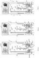
Figure 1 shows a schematic section view of the water heater of the present invention according to a first possible executive variant, where said water heater is equipped with only one auxiliary heating device which acts as a pre-heater; -
Figure 2 shows the path of the water during a withdrawal of hot water from the water heater ofFigure 1 with closed by-pass duct and open inlet duct; -
Figure 3 shows a possible path of the water during a withdrawal of hot water from the water heater ofFigure 1 with an open by-pass duct and a closed inlet duct; -
Figure 4 shows a block diagram of a possible management method of the water heater ofFigure 1 ; -
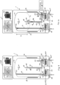
Figure 5 shows a schematic section view of the water heater of the present invention according to a second possible executive variant, where said water heater is equipped with at least a auxiliary heating device which acts as a pre-heater and with at least a auxiliary heating device which acts as a post-heater; -
Figure 6 shows the path of the water during a withdrawal of hot water from the water heater ofFigure 5 with closed by-pass duct and open inlet duct; -
Figure 7 shows a possible path of the water during a withdrawal of hot water from the water heater ofFigure 5 with an open by-pass duct and a closed inlet duct; -
Figure 8 shows a block diagram of a possible management method of the water heater ofFigure 5 ; -
Figure 9 shows a schematic section view of the water heater of the present invention according to a third possible executive variant, where said water heater is equipped with at least a auxiliary heating device which acts as a pre-heater, at least an auxiliary heating device which acts as a post-heater and with an adjustable diverter means; -
Figure 10 shows a possible path of the water during a withdrawal of hot water from the water heater ofFigure 9 ; -
Figure 11 shows a block diagram of a possible management method of the water heater ofFigure 9 ; -
Figure 12 shows a schematic section view of the water heater of the present invention according to a fourth possible executive variant, where said water heater is equipped with at least an auxiliary heating device which acts as a pre-heater arranged along said by-pass duct and with an adjustable diverter means; -
Figure 13 shows a possible path of the water during a withdrawal of hot water from the water heater ofFigure 12 ; -
Figure 14 shows a block diagram of a possible management method of the water heater ofFigure 12 . - The features of a storage water heater or the like according to the present invention and of the relative management method are now described using the references contained in the figures.
- The parameters and functions/conditions and the respective references used hereinafter in the description are listed below:
- 3u: storage water temperature in the proximity of the top zone of the tank, substantially that adjacent to the upper cap (or dome) of the same tank;
- ϑd: storage water temperature in the proximity of the lower zone of the tank, substantially that adjacent to the lower cap of the same tank;
- ϑb: storage water temperature in the proximity of the outlet of the by-pass duct;
- ϑo: "temperature out", i.e. the temperature of the water exiting the tank of the water heater;
- ϑ1: "temperature in", i.e. the temperature of the storage make-up water, generally withdrawn from the water network, following a withdrawal;
- ϑ2: "temperature heat", optional parameter identifying the value of the temperature of the water at the outlet of the post-heater, when provided, of the water heater; ϑ2 allows monitoring the value of the temperature of the water supplied by the water heater by checking whether it respects or not the comfort temperature Tc;
- Tm: the average temperature of the water of the storage and may be calculated as: Tm=a*ϑu + b*ϑd, where "a" e "b" are percentage values that act as weights in order to carry out a weighted average and may depend on, for example, the capacity of the tank and/or entity of the withdrawal (or tapping) and/or on the reactivity and readiness degree that shall be given to the water heater;
- Tc: comfort temperature, temperature that may be set by the manufacturer and/or installer and/or user below which the storage water may not be supplied;
- Tset: set point temperature, temperature at which the storage may be heated/maintained and may be set by the manufacturer and/or installer and/or user;
- X: is a hysteresis value and may be used to avoid frequent and subsequent re-ignitions of the main heating device; it is generally set by the manufacturer and/or installer based on the type of water heater and/or the type and shape of the plant or the like and may vary between 3=12, preferably between 5÷8 (dimensionless quantity);
- BOOST: additional function of the water heater which allows for an additional heating, compared to that provided via the main heating device, at least of the inlet water in the water heater via at least a of the auxiliary heating devices provided by said water heater; the BOOST function may be set by default and therefore always implemented by the water heater, or a function selectable at discretion by the user or by the installer as needed (therefore, it may be voluntarily deactivated if not desired);
- FL: represents a reference value for the amount of make-up water flow so as to be able to determine whether the withdrawal in progress is a small withdrawal or a large withdrawal. The withdrawal methods are preferably referred to the EN 16147 standard which describes the product performance test procedure, and defines the type of withdrawal based on the energy content of the water withdrawn from the storage tank; for example, a withdrawal is defined as small when it has an energy content less than 1.4 kWh;
- h: distance between the outlet of the by-pass duct and the inlet of the outlet duct of the water heater;
- v: represents a portion of the volume of the storage which substantially develops between the outlet of the by-pass duct and the inlet of the outlet duct, said volume "v" being identified/represented in the
Figures 3 ,7 ,10 and13 via a dashed line. - It should be noted that the arrows shown in the accompanying figures essentially indicate the path of the water entering and exiting the water heater according to the present invention.
- The term storage water heater is herein to be understood as any device capable of heating water in a storage tank, in particular domestic hot water for hygienic uses, until reaching a certain temperature herein defined as the set-point temperature T. set.
- As clearly shown in the accompanying
figures, 1 indicates, as a whole, thestorage water heater 1 according to the present invention, hereinafter referred to asonly water heater 1, for clarity of description. - Generally, said
water heater 1 may comprise at least a heating device, at least astorage tank 10 wherein water is stored and heated, at least a control and management unit capable of controlling said at least a heating device, at least ainlet duct 11 through which water may be introduced into thetank 10, at least aoutlet duct 12 through which water may be sent/withdrawn from thetank 10, saidinlet ducts tank 10. - The heating device may be of the electric type, i.e. comprising at least a electric device such as for example electric resistances or the like, or of the heat pump type, a variant illustrated by way of a non-limiting example in the accompanying figures, solar energy, gas, geothermal or the like or possible combinations thereof. Generally, in a storage water heater the water inside the storage tank has a stratification according to the temperature, said stratification being due to the heating process caused by the heating elements and by the density of the water. In fact, the hottest water tends to migrate and settle in the top part of the tank, while the colder water tends to settle in the lower part of the same tank.
- According to a preferred variant, the
outlet section 110 of theinlet duct 11 is preferably positioned in the proximity of the lower zone of the saidtank 10, while theinlet section 120 of theoutlet duct 12 is preferably positioned in the proximity of the median or, even more preferably, top zone of the saidtank 10. - During the operation of the
water heater 1, such arrangement determines a water make-up, generally from the water network, in the lower area of thetank 10 and a withdrawal of hot water in the upper zone thereof, thus keeping the stratification of the water based on the temperature thereof and essentially guaranteeing the withdrawal and supply of hot water. - According to a preferred variant, said
water heater 1 comprises at least two heating devices, of which preferably at least a main and at least a auxiliary. - In general, "main" heating device refers to as a device which is designed to heat water in normal/standard conditions, while "auxiliary" is to be understood as a device designed to heat water in particular conditions, for example when it is preferable to have a heat source in addition to the main one.
- Of said at least two heating devices may be identified:
- at least a first heating device, herein identified as "main", which may comprise a heat pump or means using the solar or geothermal energy or the like; and
- at least a second heating device, herein identified as "auxiliary", which may comprise heaters, preferably of the instantaneous type, comprising, for example, electric resistances or the like.
- Preferably, according with a possible executive variant, shown by way of a non-limiting example in the accompanying figures:
- said at least a first main heating device comprises a
heat pump 2 provided with at least acompressor 22, aevaporator 21, a lamination member and acondenser 20 suitably arranged so as to heat the water of the storage, for example, according to a possible executive variant, said condenser may be arranged in contact with/around the walls of thetank 10 so as to be able to cooperate, at least thermally, therewith, and heat the water contained in thesame tank 10; - said at least a second 4 auxiliary heating device comprises at least a electric heater and may be arranged externally to the
storage tank 10. - Preferably, according to possible executive variants, said
second device 4 may be installed along theinlet duct 11, so as to act as a pre-heater, i.e., be able to heat the make-up water entering thetank 10, hereinafter referred to aspre-heater 4. According to a possible embodiment variant, provided by way of a non-limiting example, saidwater heater 1 may further comprise at least athird heating device 5, herein identified as "auxiliary", which may comprise heaters, preferably of the instantaneous type, comprising, for example, electric heaters, electric resistances or the like. - Said third
auxiliary device 5 is preferably installed along theoutlet duct 12 so as to be able to act as a post-heater, i.e. be able to heat the water supplied exiting thetank 10, hereinafter referred to aspost-heater 5, and may be arranged externally to saidstorage tank 10. - In such case, therefore, said
water heater 1 simultaneously comprises at least apre-heater 4 and at least apost-heater 5. - Generally, it is possible to use an auxiliary device, both when it acts as a
pre-heater 4 and when it acts as apost-heater 5, which may be equipped with power regulating means which allow the energy supply, provided by the auxiliary device to be managed in relation to the comparison between the energy contents: of the storage water and of the recirculation water and/or of the storage water and of the make-up and/or of the storage water and of the water supplied by thewater heater 1. - According to a preferred variant, said
second device 4 is installed upstream of theoutlet section 110 of theinlet duct 11, while saidthird device 5 is installed downstream of theinlet section 120 of theoutlet duct 12. - The arrangement of said second 4 and third 5 heating device, which, as said, are preferably external to the
tank 10, allows for a convenient inspection and a possible easy replacement thereof. - For clarity of description, the inlet and outlet sections of the
pre-heater 4 and of thepost-heater 5, as well as theinlet 11 andoutlet 12 ducts whereon they may be installed, are defined in relation to the normal operation ofwater heater 1, i.e. to the making up cold water and supplying hot water during a withdrawal in progress. Thewater heater 1 may further comprise: - at least a
first temperature sensor 61 arranged in the proximity of the top zone of thetank 10 and capable of detecting the temperature 3u of the storage water; and/or - at least a
second temperature sensor 62 arranged in the proximity of the lower zone of thetank 10 and capable of detecting the temperature 4d of the storage water; and/or - at least a
third temperature sensor 63, preferably arranged downstream of theoutlet section 41 of thepre-heater 4, of thetank 10 and capable of detecting the temperature 31; and/or - at least a
fourth temperature sensor 64 arranged in the proximity/along theoutlet duct 12 of thetank 10, preferably upstream of theinlet section 50 of thepost-heater 5 when provided, and capable of detecting the temperature 4o; and/or - at least a
fifth temperature sensor 65 arranged in the proximity of the outlet of a by-pass duct of thetank 10 and capable of detecting the temperature 3b; and/or - at least a
sixth temperature sensor 66 arranged in the proximity/along theoutlet duct 12 of thetank 10, preferably downstream of theoutlet section 51 of thepost-heater 5, when provided, and capable of detecting at least the temperature 32; and/or - at least a
flow sensor 60 capable of detecting the water flow entering or exiting thetank 10, i.e. the water flow crossing theinlet duct 11 or theoutlet duct 12. - Preferably, said sensors are suitably connected and communicating with said control unit.
- In general, said
flow sensor 60 may be installed along theinlet duct 11. - Nothing prevents said
flow sensor 60 from being installed along theoutlet duct 12, as the general purpose of theflow sensor 60 is to detect whether or not a water withdrawal/make up from/into thetank 10 is in progress. - In general, it is possible to evaluate and classify the withdrawal in progress as small or large by comparing the value of the flow F detected by the
flow sensor 60 with the reference value FL. - The
water heater 1 is characterised in that it comprises at least a by-pass duct 13, hereinafter referred to as only by-pass 13 for descriptive convenience, capable of deviating, entirely or partially, the water flow entering thetank 10 so as to guide and convey it in a zone of thetank 10 placed at a height higher than theoutlet section 110 of theinlet duct 11 and at a height lower than theinlet section 120 of theoutlet duct 12. - Preferably, therefore, said by-
pass 13 guides and conveys the water entering thetank 10 in a zone of the saidtank 10 comprised between theoutlet section 110 of theinlet duct 11 and theinlet section 120 of theoutlet duct 12. - Said by-
pass 13 substantially extends between theinlet duct 11, to which it is connected, and the zone of thetank 10 wherein it discharges/introduces the make-up water, said by-pass 13 being suitably shaped so as to comprise: - at least a
inlet 130 suitably connected to saidinlet duct 11, for example via a diverter means 8 described shortly; - at least a
outlet 131 arranged inside thetank 10, preferably arranged, as already mentioned, between theoutlet section 110 of theinlet duct 11 and theinlet section 120 of theoutlet duct 12. - Preferably, the position of said
outlet 131 inside thetank 10 may be varied as necessary so that saidoutlet 131 may be located in the upper or middle or lower zone of the saidtank 10, substantially regulating, for example, the longitudinal extension of the said by -pass 13. - Such possible adjustment of the position of the
outlet 131 of the by-pass 13 allows the distance "h" to be adjusted and defined, while maintaining fixed the position of theinlet section 120 of the outlet duct 12 (seeFigures 3 ,7 ,10 and13 ). - In essence, by increasing/reducing the longitudinal extension of the said by-
pass 13, the distance h is reduced/increased and consequently the volume "v". - The choice of the value of the distance h, which may be made in the design or construction step, allows the entity of the volume "v" and therefore the quantity of water of the storage heated through the introduction of hot water heated by the
pre-heater 4 to be determined/modified, according to the methods described shortly, and introduced via the by-pass 13. - As described below, by reducing the volume v, the make-up water, heated by the
pre-heater 4, mixes, by heating it with a smaller quantity of water of the storage, making thewater heater 1 more ready to satisfy the user. - According to different executive embodiments, the by-
pass 13 provides for at least aportion 134, herein referred to asoutlet portion 134, which develops and is housed inside thetank 10 and whereon said at least aoutlet 131 is obtained/placed. Preferably, saidoutlet portion 134 is arranged substantially vertically inside thetank 10 and extends from a zone in the proximity of the bottom of thesame tank 10, preferably engaging from the same bottom, to a median or upper zone of thetank 10 based on the longitudinal development thereof correlated to the established/chosen distance h. - According to a possible variant, the by-
pass 13 may be shaped substantially as an "L" or the like so as to be able to provide for: - at least a
first portion 133, preferably arranged externally to thetank 10, whereon saidinlet 130 is obtained/placed, and - at least a second portion, preferably arranged inside the
tank 10, adapted to define saidoutlet portion 134 and the distance h, - According to different executive embodiments of the present invention, all falling within the same inventive concept, it is possible to identify at least two different installations of the
pre-heater 4 identified and illustrated herein, by way of a non-limiting example, as Case A and Case B. - According to such variant, said
pre-heater 4 is preferably positioned and installed along the inlet duct 11 (see for example the variants ofFigures 1-3 , ofFigures 5-7 , ofFigures 9-10 ). - Preferably, the
inlet 130 of the said by-pass 13 is placed along theinlet duct 11 downstream of thepre-heater 4, i.e. between theoutlet 41 of thepre-heater 4 and theoutlet section 110 of theinlet duct 11, preferably externally with respect to thetank 10. - According to such variant, said
pre-heater 4 is preferably positioned and installed along the by-pass duct 13 (see for example the variant ofFigures 12-13 ), for example along saidfirst portion 133. - Preferably, the
inlet 130 of the said by-pass 13 is placed along theinlet duct 11 upstream of theinlet 40 of thepre-heater 4. - Preferably said
water heater 1 is further provided with at least a diverter means 8, hereinafter referred to asdiverter valve 8, preferably of the electrically or mechanically controllable type, such as for example solenoid valves, motorised valves or the like, adapted to connect said by-pass duct 13, preferably theinlet 130 thereof, to saidinlet duct 11. - Said
diverter valve 8, based on the type thereof, is capable of deviating the water entering thetank 10 either towards the by-pass 13 or towards theoutlet section 110 or of possibly dividing it between both according to proportions set by the manufacturer and/or installer and/or user. - For example, said
diverter valve 8 may be of the type: - ON/OFF, i.e. capable of being either only opened or only closed by deviating the make-up water either towards the by-
pass 13 or towards theoutlet section 110, for example as in the case of the variants shown, by way of a non-limiting example in theFigures 1-3 or in theFigures 5-7 ; or - adjustable, i.e. registrable between the position of maximum opening and closing, by deviating the make-up water either towards the by-
pass 13 or towards theoutlet section 110 or deviating it therebetween, for example as in the case of the depicted variants, by way of a non-limiting example in theFigures 9-10 or in theFigures 12-13 . - According to a preferred variant, a
controllable diverter valve 8 is placed along theinlet duct 11 in the section in which the by-pass 13 engages saidinlet duct 11, saiddiverter valve 8 therefore acting as a union and connecting element among the parts and being also able to be installed externally to thetank 10. - In essence, along the
inlet duct 11 there is adiverter valve 8 capable of deviating, entirely or partially, the flow of make-up water entering thetank 10 so that it may be: - i. totally diverted towards the
outlet section 110 of theinlet duct 11, introducing the make-up water in the proximity of the lower zone of the tank 10 (see for exampleFigure 2 or6 ), when said divertervalve 8 is totally closed, for example in position "M=0" (mode i); or - ii. totally diverted towards the
outlet 131 of the by-pass 13, by introducing the make-up water at said distance h from the inlet section 120 (see for exampleFigure 3 or7 ), when said divertervalve 8 is totally open, for example in position "M=1" (mode ii); or - iii. divided between said by-
pass 13 and saidoutlet section 110, if saiddiverter valve 8 is of the adjustable type (Figure 10 or13 ) and partially open (mode iii). - In general, the make-up water, in the entirety or a portion thereof, may be advantageously heated or pre-heated through the
pre-heater 4 according to methods described shortly. - In particular, with reference to the variant of the Case A, it should be noted that the entire make-up water is heated, regardless of whether it is introduced into the
tank 10 via theinlet duct 11 only (mode i) or the by-pass 13 only (mode ii) or via both (mode iii), while in the variant of the case B only the make-up water which is diverted and passed through the by-pass 13 is heated. - Some considerations regarding the heating and the introduction of the make-up water into the
tank 10 are provided below. - In general, the
water heater 1 is able to operate with the modes i), ii) and iii) reported above, regardless of whether the configuration thereof complies with the Case A or the Case B, said Cases A and B differing substantially only by the arrangement of thepre-heater 4. - Furthermore, the
water heater 1 is able to operate in mode i) and/or ii) even if it is equipped with an adjustabletype diverter valve 8, as it is sufficient to completely close thevalve 8 to implement mode i) and open it completely to implement mode ii). - In such circumstance, the temperature Tc or Tset is reached more slowly, because the pre-heated water, introduced into the lower zone of the
tank 10, tends to mix with all the water of the storage. - In such circumstance the achievement of the temperature Tc or Tset is quicker, at least for a portion v of the volume of the storage, since the pre-heated water, introduced at a distance h from the
inlet section 120, tends to mix with the water of the volume v, said volume v being only a part/portion of the entire volume of the storage of the tank 10 (Figure 3 or7 ). - Furthermore, the
pre-heater 4 may heat the water substantially up to Tc, Tm or Tset or in general up to a temperature substantially similar to that of the water in the proximity of the zone of the storage into which it is introduced (ϑb), so as to preserve and meet the temperature stratification of the storage. - Such circumstance represents a hybrid/intermediate situation with respect to the methods i) and ii), the achievement of the temperature Tc or Tset being correlated to the adjustment degree of the
diverter valve 8 and to the amount of make-up water which is introduced respectively via the by-pass 13 and the outlet section 110 (Figure 10 ). - Generally, the configuration of the Case B, providing for heating only the make-up water which crosses the by-
pass duct 13, allows the stratification of thetank 10, to be preserved more efficiently. - In fact, the make-up water introduced by means of the
outlet section 110 of theinlet duct 11 is not heated and considering that it has a temperature substantially equal to the temperature of the water network, it does not substantially alter the stratification of the storage. - Such advantage is noticeable for the various water make-up methods of the Case B, because:
- in mode i) the make-up water passes exclusively through the
inlet duct 11 and is introduced into thetank 10 at network temperature; - in mode ii) the make-up water passes exclusively through the by-
pass 13 and is introduced into the pre-heated tank, preferably at a temperature substantially equal to 3b; - in the mode iii) the make-up water passing through the
inlet duct 11 is introduced into thetank 10 at network temperature, while that passing through the by-pass duct 13 is introduced pre-heated into the tank, preferably at a temperature substantially equal to ϑb. - A possible management method of the
water heater 1 shall now be described, by way of a non-limiting example, which may preferably be implemented via the control unit with which saidwater heater 1 is provided, said management method providing for different logics based on the fact that saidwater heater 1 comprises only thepre-heater 4 or both thepre-heater 4 and thepost-heater 5 or is configured according to the Case A or the Case B or is equipped with an ON/OFF type or adjustable diverter valve. - Said control unit is therefore capable of controlling and commanding the different components of the
water heater 1, such as for example thediverter valve 8, and/or both the main and auxiliary heating devices. - For better clarity of description, in
Figures 4 ,8 ,11 and14 some components of thewater heater 1 have been indicated with acronyms, i.e. F: value detected by theflow sensor 60; HP:main heating device 2, IST1: pre-heater 4, IST2: post-heater 5, M: diverter valve 8 (such acronyms are also shown in theFigures 1 ,5 ,9 ,12 ). - Furthermore, still with reference to
Figures 4 ,8 ,11 and14 , it should be noted that in the block diagrams the rectangle shape represents an action, for example the activation of a heating device, while the diamond shape represents a control, for example a comparison among temperatures. - Said management method is aimed at controlling/coordinating different components of the
water heater 1 such as, for example, at least the different heating devices of thewater heater 1, both said at least amain device 2 and one or more of saidauxiliary devices diverter valve 8, based on the functions to be implemented, whether standard/normal or additional. - The management method may consider different factors in order to implement such control/coordination, such as for example the presence/absence of a withdrawal, the number and/or type of said heating devices, and/or the set-point temperature Tset and/or the temperature Tc and/or the temperature of the storage water which may be possibly represented by one or more of the temperatures 3u and/or 3d and/or ϑb and or Tm and/or of the inlet 31 or outlet ϑo water temperature.
- Said management method is characterised in that it implements one or more supplementary heating functions, by one or more of said
auxiliary devices - the presence or not of a withdrawal; and
- the control of at least the temperature of the water supplied 4o;
- In general, according to different possible executive variants, the non-activation or the deactivation of at least one or more of said additional functions may depend on at least the absence or end of a withdrawal.
- Hereinafter, the term "no withdrawal", without any limiting intent, is to be referred to as both the lack of a withdrawal and the end thereof, these conditions corresponding to measurements of the
flow sensor 60 substantially equal to zero. In general, said additional functions may comprise, for example, at least the BOOST function, the POST-HEATING function or the like. - Said management method of the
water heater 1 may comprise at least the following phases. - The first phase P1, S1 of the method according to the present invention, provided by all the variants of said method illustrated herein, provides for verifying, via the
flow sensor 60, whether or not a hot water withdrawal is in progress and based on such condition, two different possible operating/management logics may be implemented, one of which is dedicated to the case of a withdrawal and the other to the case of absence of a withdrawal. - With reference to
Figure 4 , a possible management method of awater heater 1 which may be equipped with at least the BOOST function and provided with theonly pre-heater 4, placed along the inlet duct 11 (Case A), and an on/off diverter means 8 shall now be described. - During a withdrawal (F≠0), said method provides for checking, through the phase P2, whether the BOOST function is selected or not.
- If the BOOST function is selected, phase P21 is provided, by activating the pre-heater 4 (IST1=ON), while if the BOOST function is disabled the
pre-heater 4 remains switched off (IST1=OFF), phase P20 and phase P4 is provided directly. The BOOST function allows the make-up water to be heated, via at least saidpre-heater 4, accelerating the heating of the storage and consequently reducing the time necessary to bring the storage substantially to Tset or to Tc. - With the BOOST function selected and the
pre-heater 4 active, implementing the phase P22 with which there is checked whether the temperature 3b is greater than the inlet one 31 is provided. - If 3b>31, the
diverter valve 8 remains in "position 0" (M=0), maintaining the by-pass duct 13 closed and leaving theinlet duct 11 open, phase P24. - In such case, the make-up of pre-heated water takes place via the
outlet section 110 of theinlet duct 11, in the lower part of thetank 10 which is then heated (Figure 2 ). - If there is no ϑb>ϑ1, the
diverter valve 8 is switched to "position 1" (M=1) by opening, preferably totally, by-pass duct 13 and closing, preferably totally,inlet duct 11, phase P23. - In such case, the make-up of pre-heated water takes place via the
outlet 131 of the by-pass 13, at a distance h from theinlet section 120 of the outlet duct 12 (Figure 3 ). - As anticipated, this allows the pre-heated water to be introduced into a zone in which the water of the storage, by virtue of the stratification phenomenon, has a higher temperature than the water of the storage in the proximity of the lower zone of the
tank 10, speeding up the recovery of the storage at a temperature Tset or the attainment of the temperature Tc, in particular of the volume v. - Furthermore, in the event of a significant withdrawal (in terms of volume of water withdrawn) or of small but successive and close withdrawals, the make-up of the storage, via by-
pass 13, of pre-heated water advantageously allows withdrawing hot or at least pre-heated water or in general with a temperature higher than the network temperature of the make-up water. - As partly anticipated, the pre-heated water may be brought, via the
pre-heater 4, to a temperature substantially equal to Tc, Tm or Tset or in general up to a temperature substantially similar to that of the water in the proximity of the storage zone wherein it is introduced, i.e. substantially equal to ϑb. - The next phase P4 provides for monitoring the value of the temperature Tm by comparing it with Tset; the aim is not to allow the water of the storage to cool too much.
- Following the comparison between Tm and Tset (phase P4):
- if Tm is lower than Tset, the next phase P40 is provided;
- if Tm is greater than Tset, the
main heating device 2 remains switched off or in stand-by (HP=OFF), phase P41. - Phase P40 is provided and implemented in the event that, as preferred, a hysteresis parameter X is subtracted from the temperature Tset in order to avoid frequent and subsequent re-ignitions of the
main heating device 2. - Said phase P40 provides for comparing Tm with Tset-X and following said comparison:
- if Tm is lower than Tset-X, the
main heating device 2 is activated (HP=ON), so as to bring the temperature of the storage back to the desired and set temperature Tset, phase P42, - if Tm is greater than Tset-X, phase P43 is provided.
- The aim of the phase P43 is to check whether the
main heating device 2 is switched on or not during the withdrawal. - In fact, the temperature at which the storage should be heated is Tset, and not Tset-X, therefore during a withdrawal:
- if the
main heating device 2 is already in operation, then it should remain switched on and phase P42 is provided, while - if the
main heating device 2 is switched off or in stand-by, then it should remain switched off or in stand-by and phase P41 is provided. - In case of no withdrawals (F=0) or at the end of a withdrawal, said method provides for switching off or keeping the
auxiliary heating device 4 switched off (IST1=OFF), phase P3. - In such conditions (F=0; IST1=OFF), the management method provides for implementing phase P4 so as to monitor the value of the temperature Tm and compare it with Tset; the aim is not to allow the storage water to cool too much due to possible heat losses or the like.
- In absence of withdrawals, therefore, the auxiliary heating device is not active and the main heating device may possibly be activated following the comparison between Tm and Tset.
- In such case, in fact, the average temperature Tm may vary mainly due to heat losses or the like which may lead to a progressive decrease in the temperature Tm. In absence of withdrawals, therefore, the auxiliary heating devices are not active and the main heating device may possibly be activated following the comparison between Tm and Tset or between Tm and Tset-X according to the phases P40-P43 previously described.
- In absence of a withdrawal, therefore, following the phase P43:
- if the
main heating device 2 is already in operation, then it should remain switched on and phase P42 is provided, while - if the
main heating device 2 is switched off or in stand-by, then it should remain switched off or in stand-by and phase P41 is provided. - With reference to
Figure 8 , a possible management method of the water heater which may be equipped with at least the BOOST function and provided with both thepre-heater 4, located along the inlet duct 11 (Case A), and the post -heater 5 and with an on/off diverter means 8. - During a withdrawal (F≠0) said method provides for checking whether the outlet water To meets the comfort temperature Tc; the aim is that of checking whether the water supplied meets the parameters set by the manufacturer and/or installer and/or user.
- Such check is carried out with the phase S2, through which there is checked whether the outlet temperature ϑo of the
water heater 1 is higher than or equal to the comfort temperature Tc (ϑo≥Tc), where: - if so, the next phase S21 of the method is provided;
- if not, phase S20 is provided by activating the post-heater 5 (IST2=ON) which provides for heating the water substantially up to Tc (post-heating) to then continue with said subsequent phase S21.
- Phase S21 provides for checking whether the BOOST function is selected or not. In fact, the method, following the control of the output temperature To, checks whether the BOOST function is set and selected or not.
- If the BOOST function is selected, phase S23 is provided, by activating the pre-heater 4 (IST1=ON), while if the BOOST function is disabled the
pre-heater 4 remains switched off (IST1=OFF), phase S22 and phase S4 is provided directly. As already mentioned, the BOOST function allows the make-up water to be heated, via at least saidpre-heater 4, accelerating the heating of the storage and consequently reducing the time necessary to bring the storage substantially to Tset or Tc. - With the BOOST function selected and the
pre-heater 4 active, implementing the phase S24 with which there is checked whether the temperature 3b is greater than the inlet one 31 is provided. - If 3b>31, the
diverter valve 8 remains in "position 0" (M=0), maintaining the by-pass duct 13 closed and leaving theinlet duct 11 open, phase S26. - In such case, the make-up of pre-heated water takes place via the
outlet section 110 of theinlet duct 11, in the lower part of thetank 10 which is then heated (Figure 6 ). - If there is no ϑb>ϑ1, the
diverter valve 8 is switched to "position 1" (M=1) by opening, preferably totally, by-pass duct 13 and closing, preferably totally,inlet duct 11, phase S25. - In such case, the make-up of pre-heated water occurs via the
outlet 131 of the by-pass 13, at a distance h from theinlet section 120 of theoutlet duct 12. - As anticipated, this allows the pre-heated water to be introduced into a zone in which the water of the storage, by virtue of the stratification phenomenon, has a higher temperature than the water of the storage in the proximity of the lower zone of the
tank 10, speeding up the recovery of the storage at a temperature Tset or the attainment of the temperature Tc, in particular of the volume v. - Furthermore, if the heat supplied by the
pre-heater 4 and/or by themain heating device 2 is not sufficient to meet the requests of the user, supplying water at a temperature Tc, thepost-heater 5 may intervene by providing the necessary heat. The next phase S4 provides for monitoring the value of the temperature Tm by comparing it with Tset; the aim is not to allow the water of the storage to cool too much. - Following the comparison between Tm and Tset (phase S4):
- if Tm is lower than Tset, the next phase S40 is provided;
- if Tm is greater than Tset, the
main heating device 2 remains switched off or in stand-by (HP=OFF), phase S41. - Phase S40 is provided and implemented in the event that, as preferred, a hysteresis parameter X is subtracted from the temperature Tset in order to avoid frequent and subsequent re-ignitions of the
main heating device 2. - Said phase S40 provides for comparing Tm with Tset-X and following said comparison:
- if Tm is lower than Tset-X, the
main heating device 2 is activated (HP=ON), so as to bring the temperature of the storage back to the desired and set temperature Tset, phase S42, - if Tm is greater than Tset-X, phase S43 is provided.
- The aim of the phase S43 is to check whether the
main heating device 2 is switched on or not during the withdrawal. - In fact, the temperature at which the storage should be heated is Tset, and not Tset-X, therefore during a withdrawal:
- if the
main heating device 2 is already in operation, then it should remain switched on and phase S42 is provided, while - if the
main heating device 2 is switched off or in stand-by, then it should remain switched off or in stand-by and phase S41 is provided. - In case of no withdrawals (F=0) or at the end of a withdrawal, said method provides for switching off or maintaining switched off the auxiliary heating devices (IST1=OFF; IST2=OFF), phase S3.
- In such conditions (F=0; IST1=OFF; IST2=OFF), the management method provides for implementing the phase S4 so as to monitor the temperature value Tm and compare it with Tset; the aim is not to allow the storage water to cool too much due to possible heat losses or the like.
- In absence of withdrawals, therefore, the auxiliary heating devices are not active and the main heating device may possibly be activated following the comparison between Tm and Tset, phase S4.
- Following the comparison between Tm and Tset (phase S4):
- if Tm is lower than Tset, the next phase S40 is provided,
- if Tm is greater than Tset, the
main heating device 2 remains switched off or in stand-by (HP=OFF) as well as thepre-heater 4, phase S41. - Phase S40 is provided and implemented in the event that, as preferred, a hysteresis parameter X is subtracted from the temperature Tset, in order to avoid frequent and subsequent re-ignitions of the
main heating device 2. - Said phase S40 provides for comparing Tm with Tset-X and following said comparison:
- if Tm is lower than Tset-X, the main heating device 2 (HP=ON) is activated, phase S42,
- if Tm is greater than Tset-X, phase S43 is provided.
- Phase S43 has the aim to check if the
main heating device 2 is switched on or not. In fact, the temperature to which the storage should be heated is Tset and not Tset-X, therefore in the absence of a withdrawal: - if the
main heating device 2 is already in operation, then it should remain switched on and phase S42 is provided, while - if the
main heating device 2 is switched off or in stand-by, then it should remain switched off or in stand-by and phase S41 is provided. - With reference to
Figure 11 , a possible management method of the water heater which may be equipped with at least the BOOST function and provided with both thepre-heater 4, located along the inlet duct 11 (Case A), and thepost-heater 5 of an adjustable diverter means 8. - The phases of the method provided for such variant are substantially the same as described with reference to the possible management method applied to a water heater which may be equipped with at least the BOOST function and provided with both the
pre-heater 4 and thepost-heater 5 and a diverter means 8 on/off (Figure 8 ). - As visible in
Figure 11 , the only different phase is phase S25', relating to the operating logic in case of withdrawal. - In fact, with the BOOST function selected and the
pre-heater 4 active, implementing phase S24 is provided, with which there is checked whether the temperature 4b is higher than the inlet one 31. - If 4b is not >31, phase S25' provides for the
diverter valve 8 to open, at least partially, said by-pass duct 13, i.e. that it is switched to a position comprised between 0<M≤1, i.e. thediverter valve 8 may take a position comprised between the position M>0 and the totally open position M=1, in other words thediverter valve 8 may not be totally closed in order to send water to the by-pass 13. - With reference to
Figure 14 , a possible management method of the water heater which may be equipped with at least the BOOST function and provided with both thepre-heater 4, located along the by-pass duct 13 (Case B), and thepost-heater 5 of an adjustable diverter means 8. - The phases of the method provided for such variant are substantially the same as described with reference to the possible management method applied to a water heater which may be equipped with at least the BOOST function and provided with both the
pre-heater 4, placed along theinlet duct 11, and thepost-heater 5 and a diverter means 8 on/off (Figure 8 ). - As visible in
Figure 14 , the phases that differ from what described are the phases S23', S25' and S26', relating to the operating logic in the event of a withdrawal. If the BOOST function is selected, phase S23' is provided, by activating the pre-heater 4 (IST1=ON), and by fully opening the diverter valve 8 (M=1) while if the BOOST function is disabled thepre-heater 4 remains switched off (IST1=OFF), phase S22, and the following phase S4 is provided directly. - Subsequently, with the BOOST function selected and pre-heater 4 active, implementing phase S24 is provided, with which there is checked whether the temperature 4b is higher than the inlet one 31.
- If 4b is not >ϑ1, phase S25' provides for the
diverter valve 8 to open, at least partially, said by-pass duct (13), i.e. that it is switched to a position comprised between 0<M≤1, i.e. thediverter valve 8 may take a position comprised between the position M>0 and the totally open position M=1, in other words thediverter valve 8 may not be totally closed in order to send water to the by-pass 13. - If ϑb>ϑ1, the
diverter valve 8 remains in "position 0" (M=0), closing or maintaining the by-pass duct 13 closed and leaving theinlet duct 11 open and pre-heater 4 is turned off or put in stand-by (IST1=OFF), phase S26'. - In such case the make-up water is not heated and is introduced at network temperature into the
tank 10 via theoutlet section 110 of theinlet duct 11. - In general, the water heater according to the present invention, thanks to the adoption of auxiliary heating devices, may install and use a smaller main heating device; that is further true in the case of the heat pumps.
- In fact, heat pumps of lower power have smaller heat exchange surfaces (evaporator/condenser) and the overall size of the same heat pump will be reduced. On the other hand, it is known that the electric heaters require, by their nature, reduced and compact overall dimensions and if they are used as auxiliary heating devices, the overall dimension of the
water heater 1 is smaller than the overall dimension of a water heater of the same power which uses only one heat pump as a heating source. - Furthermore, the adoption of instantaneous heating devices allows the volume of the storage to be reduced, because such devices are able to effectively compensate for deep and frequent withdrawals by the user.
- It should be noted that the adoption of smaller storages allows for the installation of smaller heat pumps, further contributing to reduce the overall dimensions of the water heater according to the present invention.
- Several variants of the invention described above are possible for the man skilled in the art, without departing from the novelty scopes of the inventive idea, as well as it is clear that in the practical embodiment of the invention the various components described above may be replaced with technically equivalent elements.
Claims (22)
- Storage water heater (1) comprising at least a heating device, at least a storage tank (10) wherein water is stored and heated, at least a control and management unit capable of controlling said at least a heating device, at least a inlet duct (11) through which water may be introduced into said tank (10), at least a outlet duct (12) through which water may be sent/withdrawn from the said tank (10),
characterised in thatit comprises at least two heating devices, of which at least a main heating device (2) and at least a second (4) auxiliary heating device adapted to act as a pre-heater (4),
and in thatsaid water heater (1) comprises at least a by-pass duct (13) capable of deviating, entirely or partially, the water flow entering said tank (10) so as to guide and convey it in a zone of the said tank (10) placed at a height higher than the outlet section (110) of the said inlet duct (11), said by-pass duct (13) extending between the inlet duct (11) to which it is connected, and the zone of the said tank (10) wherein it discharges/introduces the make-up water, said by-pass duct (13) being shaped so as to comprise:- at least a inlet (130) connected to said inlet duct (11);- at least a outlet (131) arranged inside said tank (10);said by-pass duct (13) providing for at least a outlet portion (134) that develops and is housed inside said tank (10) and whereon said at least a outlet (131) is obtained/placed. - Storage water heater (1) according to the previous claim, wherein said outlet portion (134) is arranged vertically inside the said tank (10) and extends from a zone in the proximity of the bottom of the said tank (10) to a median or upper zone of the same tank (10) based on the longitudinal development thereof.
- Storage water heater (1) according to the previous claim, wherein said by-pass duct (13) is shaped so as to be able to provide for:- at least a first portion (133), arranged externally to said tank (10), whereon said inlet (130) is obtained/placed, and- at least a second portion, arranged inside the tank (10), adapted to define said outlet portion (134).
- Storage water heater (1) according to any previous claim, wherein said at least a outlet (131) of said by-pass duct (13) is arranged between the outlet section (110) of the said inlet duct (11) and the inlet section (120) of the said outlet duct (12).
- Storage water heater (1) according to any previous claim, wherein said water heater (1) is further provided with a at least a diverter means (8) adapted to connect said by-pass duct (13) to said inlet duct (11).
- Storage water heater (1) according to any previous claim, wherein said at least a diverter means (8) is of the electrically or mechanically controllable type.
- Storage water heater (1) according to the previous claim, wherein said at least a diverter means (8) is of the ON/OFF type, i.e. capable of being either only open or only closed.
- Storage water heater (1) according to the previous claim 6, wherein said at least a diverter means (8) is of the adjustable type, i.e. registrable between the opening and closing position.
- Storage water heater (1) according to any previous claim, wherein said at least a pre-heater (4) is installed along said inlet duct (11) and said inlet (130) of the said by-pass duct (13) is placed along said inlet duct (11), downstream of the said pre-heater (4).
- Storage water heater (1) according to any previous claim 1 to 8, wherein said at least a pre-heater (4) is installed along said by-pass duct (13) and said inlet (130) of the said by-pass duct (13) is placed along said inlet duct (11), upstream of the inlet (40) of the said pre-heater (4).
- Storage water heater (1) according to any previous claim, wherein said water heater (1) further comprises at least a third (5) auxiliary heating device, installed along said outlet duct (12) so as to act as a post-heater (5).
- Storage water heater (1) according to one or more of the previous claims, wherein:- said first main heating device (2) comprises a heat pump or means that use the solar energy or the geothermal energy or the like;- said second (4) and third auxiliary heating device (5) comprise heaters of the instantaneous type.
- Storage water heater (1) according to the previous claim 11 or 12, wherein said second (4) and third auxiliary heating device (5) and said at least a diverter means (8) are installed externally to said tank (10).
- Storage water heater (1) according to any previous claim, wherein said water heater (1) is further provided with:- at least a first temperature sensor (61) arranged in the proximity of the top zone of the said tank (10) and capable of detecting the temperature 3u of the storage water; and/or- at least a second temperature sensor (62) arranged in the proximity of the lower zone of the said tank (10) and capable of detecting the temperature 4d of the water of the storage; and/or- at least a third temperature sensor (63) capable of detecting the temperature 31; and/or- at least a fourth temperature sensor (64) arranged in the proximity/along said outlet duct (12) of the said tank (10), and capable of detecting the temperature out 3o; and/or- at least a fifth temperature sensor (65) arranged in the proximity of the outlet (131) of the said by-pass duct (13) and capable of detecting the temperature 3b; and/or- at least a sixth temperature sensor (66) arranged in the proximity/along said outlet duct (12) of the said tank (10), downstream of the outlet section (51) of the said post-heater (5) when provided, and capable of detecting at least the temperature ϑ2; and/or- at least a flow sensor (60) capable of detecting the water flow entering or exiting into/from said tank (10).
- Management method of a storage water heater (1) according to the previous claims 1 to 14, said management method being aimed at controlling/coordinating different components of the said water heater (1) such as at least the different heating devices of the said water heater (1), both said at least a main device (2) and one or more of said auxiliary devices (4, 5), and/or at least said diverter means (8),
characterised in that
said management method implements one or more supplementary heating functions, by one or more of said auxiliary devices (4, 5), of the water introduced and/or withdrawn from the storage, where the activation of at least one or more of said additional functions depending on at least:- the presence or not of a withdrawal; and- the control of at least the temperature of the water supplied ϑo. - Management method of a storage water heater (1) according to the previous claim, wherein said supplementary functions comprise at least a BOOST function, which allows for an additional heating, with respect to that provided by said main heating device (2) at least of the water entering into said water heater (1) by at least said second auxiliary heating device (4).
- Management method of a storage water heater (1) according to the previous claim, wherein said water heater (1) may be equipped with at least said BOOST function and is provided with only said pre-heater (4), placed along said inlet duct (11), and a diverter means (8) of the on/off type, where, following the verification phase of a withdrawal (P1), in case of a withdrawal, said method provides for:- verifying if the BOOST function (P2) is selected or not:- if said BOOST function is selected, the activation of said pre-heater (4) (P21) is provided,- if said BOOST function is disabled, said pre-heater (4) remains switched off (P20) and the next phase (P4) is provided directly;- with the BOOST function selected and said pre-heater (4) active, the temperature 4b is checked (P22) whether greater than the inlet one 31:- if ϑb>ϑ1 (P24), said diverter means (8) remains in "position 0" maintaining said by-pass duct (13) closed and leaving said inlet duct (11) open,- if 3b is not >ϑ1 (P23), said diverter means (8) is switched to "position 1" (M=1) opening said by-pass duct (13) and closing said inlet duct (11).- monitoring the value of the temperature Tm by comparing it with the value of the temperature Tset (P4), where:- if Tm is lower than Tset, the next phase (P40) is provided;- if Tm is greater than Tset, said main heating device (2) remains switched off or in stand-by (P41).- subtracting a hysteresis parameter X from said set-point temperature Tset and comparing it with said Tm (P40), where:- if Tm is lower than Tset-X, said main heating device (2) (P42) is activated,- if Tm is greater than Tset-X, checking whether said main heating device (2) is switched on or not during the withdrawal (P43) is provided:- if said main heating device (2) is already in operation, it remains switched on, whereas- if said main heating device (2) is switched off or in stand-by, it remains switched off or in stand-by.
- Management method of a storage water heater (1) according to the previous claim 16 or 17, wherein said water heater (1) may be equipped with at least said BOOST function and is provided with only said pre-heater (4), placed along said inlet duct (11), and with a diverter means (8) of the on/off type, where, following the verification phase of a withdrawal (P1), in the absence of a withdrawal, said method provides for:- switching and maintaining said pre-heater (4) (P3) switched off;- monitoring the value of the temperature Tm by comparing it with the value of the temperature Tset (P4), where:- if Tm is lower than Tset, the next phase (P40) is provided,- if Tm is greater than Tset, said main heating device (2) remains switched off or in stand-by (P41);- subtracting a hysteresis parameter X from said set-point temperature Tset and comparing it with said Tm (P40), where:- if Tm is lower than Tset-X, said main heating device (2) (P42) is activated,- if Tm is greater than Tset-X, checking whether said main heating device (2) is switched on or not in the absence of a withdrawal (P43) is provided:- if said main heating device (2) is already in operation, it remains switched on, whereas- if said main heating device (2) is switched off or in stand-by, it remains switched off or in stand-by.
- Management method of a storage water heater (1) according to the previous claim 16, wherein said water heater (1) may be equipped with at least said BOOST function and is provided with both the said pre-heater (4), placed along said inlet duct (11), and the said post-heater (5) and with a diverter means (8) of the on/off type, wherein, following the verification phase of a withdrawal (S1), in case of a withdrawal said method provides for:- checking if the outlet temperature 3o meets the comfort temperature Tc (S2), i.e. whether said outlet temperature ϑo is greater than said comfort temperature Tc (ϑo≥Tc), if so, the next phase (S21) of the method is provided; if not (S20) said post-heater (5) is activated to then proceed with said next phase (S21);- checking if said BOOST function is set/selected (S21):- if said BOOST function is selected (S23), said pre-heater (4) is activated,- if said BOOST function is disabled (S22) said pre-heater (4) remains switched off;- checking if the temperature 3b is greater than the inlet one 31 (S24):- if ϑb>ϑ1 (S26), said diverter means (8) maintains said by-pass duct (13) closed and leaves said inlet duct (11) open,- if 3b is not >ϑ1 (S25), said diverter means (8) opens said by-pass duct (13) and closes said inlet duct (11);- monitoring the value of the temperature Tm by comparing it with the value of the temperature Tset (S4), where:- if Tm is lower than Tset, the next phase (S40) is provided;- if Tm is greater than Tset, said main heating device (2) remains switched off or in stand-by (S41).- subtracting a hysteresis parameter X from said set-point temperature Tset and comparing it with said Tm (S40), where:- if Tm is lower than Tset-X, said main heating device (2) (S42) is activated,- if Tm is greater than Tset-X, checking whether said main heating device (2) is switched on or not during the withdrawal (S43) is provided:- if said main heating device (2) is already in operation, it remains switched on, whereas- if said main heating device (2) is switched off or in stand-by, it remains switched off or in stand-by.
- Management method of a storage water heater (1) according to the previous claim 16 or 19, wherein said water heater (1) may be equipped with at least said BOOST function and is provided with both the said pre-heater (4), placed along said inlet duct (11), and the said post-heater (5) and with a diverter means (8) of the on/off type, where, following the verification phase of a withdrawal (S1), in the absence of a withdrawal, said method provides for:- switching off and maintaining said pre-heater (4) and said post-heater (5) (S3) switched off;- monitoring the value of the temperature Tm by comparing it with the value of the temperature Tset (S4), where:- if Tm is lower than Tset, the next phase (S40) is provided,- if Tm is greater than Tset, said main heating device (2) remains switched off or in stand-by (S41);- subtracting a hysteresis parameter X from said set-point temperature Tset and comparing it with said Tm (S40), where:- if Tm is lower than Tset-X, said main heating device (2) (S42) is activated,- if Tm is greater than Tset-X, checking whether said main heating device (2) is switched on or not in the absence of a withdrawal (S43) is provided:- if said main heating device (2) is already in operation, it remains switched on, whereas- if said main heating device (2) is switched off or in stand-by, it remains switched off or in stand-by.
- Management method of a storage water heater (1) according to the previous claim 16 or 19, wherein said water heater (1) may be equipped with at least said BOOST function and is provided with both said pre-heater (4), placed along said inlet duct (11), and said post-heater (5), and with a diverter means (8) of the adjustable type, said method providing for the same phases as the management method according to the previous claim 19 and differs in that, in case of a withdrawal:
when checking the temperatures 3b and 31 (S24), if 3b is not >ϑ1 (S25'), said diverter means (8) opens, at least partially, said by-pass duct (13). - Management method of a storage water heater (1) according to the previous claim 16 or 19, wherein said water heater (1) may be equipped with at least said BOOST function and is provided both with said pre-heater (4), placed along said by-pass duct (13), and said post-heater (5), and with a diverter means (8) of the adjustable type, said method providing for the same phases as the management method according to the previous claim 19 and differs in that, in case of a withdrawal:- by controlling if said BOOST function is set/selected (S21):- if said BOOST function is selected, the activation of said pre-heater (4) and the full opening of said diverter means (8) is provided;- by controlling if the temperature 3b is greater than the inlet one 31 (S24):- if 3b is not >31 (S25'), said diverter means (8) opens, at least partially, said by-pass duct (13);- if ϑb>ϑ1, said diverter means (8) closes or maintains said by-pass duct (13) closed and said pre-heater (4) is switched off or placed in stand-by (S26').
Applications Claiming Priority (1)
| Application Number | Priority Date | Filing Date | Title |
|---|---|---|---|
| IT202200025026 | 2022-12-06 |
Publications (3)
| Publication Number | Publication Date |
|---|---|
| EP4382818A1 true EP4382818A1 (en) | 2024-06-12 |
| EP4382818C0 EP4382818C0 (en) | 2025-09-03 |
| EP4382818B1 EP4382818B1 (en) | 2025-09-03 |
Family
ID=85462213
Family Applications (1)
| Application Number | Title | Priority Date | Filing Date |
|---|---|---|---|
| EP23212531.0A Active EP4382818B1 (en) | 2022-12-06 | 2023-11-28 | Storage water heater equipped with at least one auxiliary heater and a by-pass duct |
Country Status (5)
| Country | Link |
|---|---|
| US (1) | US20240183542A1 (en) |
| EP (1) | EP4382818B1 (en) |
| CN (1) | CN118149465A (en) |
| ES (1) | ES3056100T3 (en) |
| PL (1) | PL4382818T3 (en) |
Citations (6)
| Publication number | Priority date | Publication date | Assignee | Title |
|---|---|---|---|---|
| WO2006111755A2 (en) * | 2005-04-21 | 2006-10-26 | Clean Heat Provision Limited | Hot water installations |
| ES2312293A1 (en) * | 2008-07-15 | 2009-02-16 | Constante Solar, S.L. | Installation, method and heat exchanger device for electrical heaters of sanitary water. (Machine-translation by Google Translate, not legally binding) |
| US20110132279A1 (en) * | 2008-03-06 | 2011-06-09 | Joseph Le Mer | Equipment for producing domestic hot water |
| DE102010034008A1 (en) * | 2010-08-11 | 2012-02-16 | Sebastian Ossadnik | Method for efficiently using solar heated industrial water in household hot water-tank system for solar thermal system, involves using small heat exchangers and large and small hot water tanks based on solar irradiation |
| EP2453334A1 (en) * | 2010-11-10 | 2012-05-16 | Ariston Thermo S.P.A. | Method for minimising daily energy consumption of a water storage heater through simplified logical processes |
| WO2022168050A1 (en) * | 2021-02-07 | 2022-08-11 | Octopus Energy Group Limited | Active water leakage detection methods and systems |
Family Cites Families (3)
| Publication number | Priority date | Publication date | Assignee | Title |
|---|---|---|---|---|
| DE20017569U1 (en) * | 2000-10-13 | 2000-12-21 | Weigerstorfer GmbH, 94078 Freyung | Hot water tank with solar energy use |
| US11262101B2 (en) * | 2017-05-09 | 2022-03-01 | Active Home Ltd. | Method and system for heating water |
| CN207365171U (en) * | 2017-10-17 | 2018-05-15 | 长安大学 | A kind of layering water-storing device of solar energy heating |
-
2023
- 2023-11-28 EP EP23212531.0A patent/EP4382818B1/en active Active
- 2023-11-28 US US18/521,022 patent/US20240183542A1/en active Pending
- 2023-11-28 ES ES23212531T patent/ES3056100T3/en active Active
- 2023-11-28 PL PL23212531.0T patent/PL4382818T3/en unknown
- 2023-12-05 CN CN202311657008.0A patent/CN118149465A/en active Pending
Patent Citations (6)
| Publication number | Priority date | Publication date | Assignee | Title |
|---|---|---|---|---|
| WO2006111755A2 (en) * | 2005-04-21 | 2006-10-26 | Clean Heat Provision Limited | Hot water installations |
| US20110132279A1 (en) * | 2008-03-06 | 2011-06-09 | Joseph Le Mer | Equipment for producing domestic hot water |
| ES2312293A1 (en) * | 2008-07-15 | 2009-02-16 | Constante Solar, S.L. | Installation, method and heat exchanger device for electrical heaters of sanitary water. (Machine-translation by Google Translate, not legally binding) |
| DE102010034008A1 (en) * | 2010-08-11 | 2012-02-16 | Sebastian Ossadnik | Method for efficiently using solar heated industrial water in household hot water-tank system for solar thermal system, involves using small heat exchangers and large and small hot water tanks based on solar irradiation |
| EP2453334A1 (en) * | 2010-11-10 | 2012-05-16 | Ariston Thermo S.P.A. | Method for minimising daily energy consumption of a water storage heater through simplified logical processes |
| WO2022168050A1 (en) * | 2021-02-07 | 2022-08-11 | Octopus Energy Group Limited | Active water leakage detection methods and systems |
Also Published As
| Publication number | Publication date |
|---|---|
| ES3056100T3 (en) | 2026-02-18 |
| EP4382818C0 (en) | 2025-09-03 |
| PL4382818T3 (en) | 2026-02-02 |
| EP4382818B1 (en) | 2025-09-03 |
| CN118149465A (en) | 2024-06-07 |
| US20240183542A1 (en) | 2024-06-06 |
Similar Documents
| Publication | Publication Date | Title |
|---|---|---|
| KR101615408B1 (en) | Hot-water supply system | |
| JP4952479B2 (en) | Water heater | |
| JP5206106B2 (en) | Water heater | |
| EP3521727B1 (en) | Storage type hot water supplying device | |
| KR101467095B1 (en) | Hot water supply system | |
| KR101467088B1 (en) | Storage type hot water supply device | |
| JP5035084B2 (en) | Heat pump hot water supply system | |
| JP5067869B2 (en) | Water heater | |
| JP2006105434A (en) | Heat pump hot water supply heating device | |
| EP4382818B1 (en) | Storage water heater equipped with at least one auxiliary heater and a by-pass duct | |
| KR100563180B1 (en) | Heat pump hot water supply device | |
| JP2012127635A (en) | Hot water supply system | |
| JP4839141B2 (en) | Heat pump water heater | |
| JP2009052798A (en) | Hot water storage water heater with bath pouring function | |
| JP2016040498A (en) | Hybrid hot water supply system | |
| EP4382817A1 (en) | Storage water tank equipped with at least one auxiliary heater and a circulator | |
| KR101579399B1 (en) | Hot water supply system | |
| JP6682002B2 (en) | Hot water storage type water heater, hot water supply method and program | |
| JP2015025624A (en) | Hot water system | |
| JP2007003057A (en) | Hot water storage water heater | |
| JP5166709B2 (en) | Water heater | |
| JP2006343033A (en) | Hot water storage water heater | |
| JP2008020099A (en) | Water heater | |
| EP1710511A2 (en) | Boiler with devices for optimising the supply of hot water for sanitary purposes, and the corresponding method | |
| JP2018071875A (en) | Hot water supply system |
Legal Events
| Date | Code | Title | Description |
|---|---|---|---|
| PUAI | Public reference made under article 153(3) epc to a published international application that has entered the european phase |
Free format text: ORIGINAL CODE: 0009012 |
|
| STAA | Information on the status of an ep patent application or granted ep patent |
Free format text: STATUS: THE APPLICATION HAS BEEN PUBLISHED |
|
| AK | Designated contracting states |
Kind code of ref document: A1 Designated state(s): AL AT BE BG CH CY CZ DE DK EE ES FI FR GB GR HR HU IE IS IT LI LT LU LV MC ME MK MT NL NO PL PT RO RS SE SI SK SM TR |
|
| STAA | Information on the status of an ep patent application or granted ep patent |
Free format text: STATUS: REQUEST FOR EXAMINATION WAS MADE |
|
| 17P | Request for examination filed |
Effective date: 20241204 |
|
| RBV | Designated contracting states (corrected) |
Designated state(s): AL AT BE BG CH CY CZ DE DK EE ES FI FR GB GR HR HU IE IS IT LI LT LU LV MC ME MK MT NL NO PL PT RO RS SE SI SK SM TR |
|
| GRAP | Despatch of communication of intention to grant a patent |
Free format text: ORIGINAL CODE: EPIDOSNIGR1 |
|
| STAA | Information on the status of an ep patent application or granted ep patent |
Free format text: STATUS: GRANT OF PATENT IS INTENDED |
|
| RIC1 | Information provided on ipc code assigned before grant |
Ipc: F24H 15/429 20220101ALI20250417BHEP Ipc: F24H 15/375 20220101ALI20250417BHEP Ipc: F24H 15/37 20220101ALI20250417BHEP Ipc: F24H 15/335 20220101ALI20250417BHEP Ipc: F24H 15/31 20220101ALI20250417BHEP Ipc: F24H 15/225 20220101ALI20250417BHEP Ipc: F24H 15/219 20220101ALI20250417BHEP Ipc: F24H 15/215 20220101ALI20250417BHEP Ipc: F24H 15/174 20220101ALI20250417BHEP Ipc: F24H 9/20 20220101ALI20250417BHEP Ipc: F24H 9/13 20220101ALI20250417BHEP Ipc: F24H 4/04 20060101ALI20250417BHEP Ipc: F24H 1/18 20220101ALI20250417BHEP Ipc: F24D 19/10 20060101ALI20250417BHEP Ipc: F24D 17/02 20060101ALI20250417BHEP Ipc: F24D 17/00 20220101AFI20250417BHEP |
|
| INTG | Intention to grant announced |
Effective date: 20250508 |
|
| GRAS | Grant fee paid |
Free format text: ORIGINAL CODE: EPIDOSNIGR3 |
|
| GRAA | (expected) grant |
Free format text: ORIGINAL CODE: 0009210 |
|
| STAA | Information on the status of an ep patent application or granted ep patent |
Free format text: STATUS: THE PATENT HAS BEEN GRANTED |
|
| AK | Designated contracting states |
Kind code of ref document: B1 Designated state(s): AL AT BE BG CH CY CZ DE DK EE ES FI FR GB GR HR HU IE IS IT LI LT LU LV MC ME MK MT NL NO PL PT RO RS SE SI SK SM TR |
|
| REG | Reference to a national code |
Ref country code: CH Ref legal event code: EP |
|
| REG | Reference to a national code |
Ref country code: DE Ref legal event code: R096 Ref document number: 602023006363 Country of ref document: DE |
|
| REG | Reference to a national code |
Ref country code: CH Ref legal event code: R17 Free format text: ST27 STATUS EVENT CODE: U-0-0-R10-R17 (AS PROVIDED BY THE NATIONAL OFFICE) Effective date: 20251006 |
|
| REG | Reference to a national code |
Ref country code: IE Ref legal event code: FG4D |
|
| U01 | Request for unitary effect filed |
Effective date: 20250922 |
|
| U07 | Unitary effect registered |
Designated state(s): AT BE BG DE DK EE FI FR IT LT LU LV MT NL PT RO SE SI Effective date: 20250925 |
|
| U20 | Renewal fee for the european patent with unitary effect paid |
Year of fee payment: 3 Effective date: 20251001 |
|
| PG25 | Lapsed in a contracting state [announced via postgrant information from national office to epo] |
Ref country code: NO Free format text: LAPSE BECAUSE OF FAILURE TO SUBMIT A TRANSLATION OF THE DESCRIPTION OR TO PAY THE FEE WITHIN THE PRESCRIBED TIME-LIMIT Effective date: 20251203 |
|
| PG25 | Lapsed in a contracting state [announced via postgrant information from national office to epo] |
Ref country code: HR Free format text: LAPSE BECAUSE OF FAILURE TO SUBMIT A TRANSLATION OF THE DESCRIPTION OR TO PAY THE FEE WITHIN THE PRESCRIBED TIME-LIMIT Effective date: 20250903 |
|
| PG25 | Lapsed in a contracting state [announced via postgrant information from national office to epo] |
Ref country code: GR Free format text: LAPSE BECAUSE OF FAILURE TO SUBMIT A TRANSLATION OF THE DESCRIPTION OR TO PAY THE FEE WITHIN THE PRESCRIBED TIME-LIMIT Effective date: 20251204 |
|
| PGFP | Annual fee paid to national office [announced via postgrant information from national office to epo] |
Ref country code: IE Payment date: 20251114 Year of fee payment: 3 |
|
| PG25 | Lapsed in a contracting state [announced via postgrant information from national office to epo] |
Ref country code: RS Free format text: LAPSE BECAUSE OF FAILURE TO SUBMIT A TRANSLATION OF THE DESCRIPTION OR TO PAY THE FEE WITHIN THE PRESCRIBED TIME-LIMIT Effective date: 20251203 |
|
| PGFP | Annual fee paid to national office [announced via postgrant information from national office to epo] |
Ref country code: ES Payment date: 20251202 Year of fee payment: 3 |
|
| REG | Reference to a national code |
Ref country code: ES Ref legal event code: FG2A Ref document number: 3056100 Country of ref document: ES Kind code of ref document: T3 Effective date: 20260218 |
|
| PG25 | Lapsed in a contracting state [announced via postgrant information from national office to epo] |
Ref country code: SM Free format text: LAPSE BECAUSE OF FAILURE TO SUBMIT A TRANSLATION OF THE DESCRIPTION OR TO PAY THE FEE WITHIN THE PRESCRIBED TIME-LIMIT Effective date: 20250903 |
|
| PG25 | Lapsed in a contracting state [announced via postgrant information from national office to epo] |
Ref country code: IS Free format text: LAPSE BECAUSE OF FAILURE TO SUBMIT A TRANSLATION OF THE DESCRIPTION OR TO PAY THE FEE WITHIN THE PRESCRIBED TIME-LIMIT Effective date: 20260103 |
|
| PG25 | Lapsed in a contracting state [announced via postgrant information from national office to epo] |
Ref country code: CZ Free format text: LAPSE BECAUSE OF FAILURE TO SUBMIT A TRANSLATION OF THE DESCRIPTION OR TO PAY THE FEE WITHIN THE PRESCRIBED TIME-LIMIT Effective date: 20250903 |
|
| PGFP | Annual fee paid to national office [announced via postgrant information from national office to epo] |
Ref country code: PL Payment date: 20251002 Year of fee payment: 3 |
|
| PG25 | Lapsed in a contracting state [announced via postgrant information from national office to epo] |
Ref country code: SK Free format text: LAPSE BECAUSE OF FAILURE TO SUBMIT A TRANSLATION OF THE DESCRIPTION OR TO PAY THE FEE WITHIN THE PRESCRIBED TIME-LIMIT Effective date: 20250903 |