Field of the invention
-
The invention relates to an elevator cab and shaft door system for narrowed spaces. For the purposes of this invention, elevator cab doors are always automatic and elevator shaft doors may also be automatic or may be manual. The invention falls within the field of construction.
Background of the invention
-
Automatic sliding lift doors have their usual concept based on practical functionality, reliability, simplicity and space saving. In particular, double-panel doors, whether central or telescopic, are used for their reliability and stability based on the wide carriage of the door panels, as well as the simplicity of construction. In the case of space constraints, especially in reconstructed buildings, more complex solutions are also applied, in particular central doors with an even number of panels, with a number of 2,4,6 to 8 panels, and telescopic doors with a number of panels of 1,2,3 to 4. Multi-panel doors were originally used for wider clear entrances, but are now also used for small narrow shafts. Many lift shafts in the former Czechoslovakia and elsewhere use shaft widths below 1200 mm.
-
These are mainly lifts with the lifting capacity of 250 kg, according to standard ČSN 27 4320. This dimension is often practically reduced by construction deviations of the floor plan and vertical projection of the shaft, which reduces the usable width of the shaft to 1160 to 1180 mm. Also, due to the minimum installation width of the JD 700 type manual doors in use, the width of the shaft at floor level does not tend to be below 1160 to 1180 mm, according to standard ON 27 4302. As a replacement for the JD type door, for example, Metron s.a. can offer 3-panel telescopic door, 700 mm wide, which, however, due to the three-row arrangement, has wide door sills, reducing the useful size of the cab and pushing the cab asymmetrically to the side.
-
The Wittur group offers the Fineline 4-panel central door, 700 mm wide, with legendary reliability, an extremely narrow door sill and an extremely small door mechanism width, which is even slightly smaller than the width of the panels when the door is open. However, when the lift is stationary when the door is open, the width of the panels does not matter, but the smaller width of the mechanism advantageously provides a greater safety margin when the lift is moving, due to the unevenness of the shaft when the panels are closed.
-
The company Vymyslický - Výtahy spol. s r.o., with
patent EP 2 607 285 B1 and utility model
CZ23627U1 , that is able to offer 6-panel doors with the width of 800mm for common small shafts, stands out in terms of dimensions. Although the arrangement of the middle panels each in a separate plane allows the use of a wide carriage for suspension of the door panel, nevertheless, this door does not exceed the reliability and, in addition, requires the use of two planes of guidance for the middle panels, i.e. a total four planes of guidance.
-
For example, the company Fermátor also offers asymmetric 4-panel doors, that is, two wide and two narrow panels, but this does not reduce the width of the mechanism or the overall width of the open door panels relative to conventional central 4-panel doors, it just provides designers with greater variability in the layout of the lift technology.
-
For the above reasons, there is the need for a simple solution where a suitable ratio of the width of the door guide mechanism to the clear opening of the door is achieved, thereby effectively utilising the ability to retract the door leaf behind the door frame without the need for an additional large construction width for the door guide mechanism. It also implies the need to address the width of the carriages of the door guide mechanism with regard to their stability. For this purpose, efforts have been made resulting in the system of elevator cab and shaft doors for narrowed spaces according to present invention.
Summary of the invention
-
The deficiencies in the prior art are eliminated by the system of elevator cab and shaft doors for narrowed spaces with the central opening of the door panels with the door guide mechanism, according to invention, the essence of which is that wherein at least one of the mentioned doors are formed by five door panels suspended on separate carriages movably mounted in three movement tracks such that a single central door panel is mounted in the rear motion track of the door guide mechanism.
-
For the purposes of the present invention, the term "rear motion track" is always understood to mean the motion track closest to the gap between the shaft and the entrance to the elevator cab. Two door edge panels are mounted on the forward motion track of the door guide and two door centre panels are mounted on the central motion track of the door guide, wherein the clear width of the door is in the range of 600 to 900 mm and wherein the width of the door guide mechanism to the clear width of the door is in the ratio of 1.3 to 1.45. The size of the door panels may be different. Because the panel in the fore-last row opens in the opposite direction to the last middle panel, this fore-last panel is mounted in front of the last panel, so it is extended so that when the door is open, there is no dangerous gap between the shaft door and the cab door on the side with the fewer panels, or this extension is replaced by the cover fixed on the panel, or the cover is fixed at the boundary of the clear opening of the door. The door width of 600 mm represents the smallest lift entrance door in use. The frame width of 120 mm is one of the most commonly used automatic door widths by various manufacturers. From the mathematical model it is clear that the optimum use is just for doors unusually designed as 5-panel central doors.
-
The second essential feature of the system of elevator cab and shaft doors for narrowed spaces with central opening of door panels is the door guide mechanism itself, applied system with five door panels suspended on separate carriages movably mounted on three motion tracks so that in the rear motion track of the door guide one central door panel is mounted, two edge door panels are mounted in the front door guide motion track, and two central door panels are mounted in the middle door guide motion track according to invention, and the essence of which is that the width of each carriage of the door guide mechanism is greater than the width of each door panel, wherein the number of upper and lower door guide motion track s is the same.
-
In this section are clarifications explaining the invention with respect also to known solutions and possibly also to standards. The width of the door is also limited by the building widths and openings. In addition to modern elevators with space saving efforts, there is a need of solutions for modernizations and existing spaces. In the Czech Republic and Slovakia there are a large number of older lifts with manual shaft doors of type JD, with a clear entrance width of 700 mm, manufactured according to the union standard ON 27 4302, which requires a building width of 1180 mm at the widest point of the opening for the JD 700-x-x-M door, which has affected also the width of the shafts used. A shaft width of 1180 mm can be encountered more often than the required shaft width of 1200 mm required by standard ČSN 27 4320 for lifts with a lifting capacity of 250 kg. From the above dimensions it is necessary to subtract constructional inaccuracies and vertical deviations, which further reduces the space for the lift door. When the following technological gaps for safe and reliable operation are taken into account, it is necessary to consider even less space for the width of the open door leaves if the lift is stationary and even less space for the door mechanism if the lift is moving. The essential width of the lift door is the entrance width of 800 mm, which is the minimum required by national regulations for persons with reduced mobility, e.g. Decree 532/2002 Coll., clause 1.7.2, or by standards such as EN 81-70. The existing 4-panel door solution is not applicable for 800 mm doors in the above mentioned shafts, because the mathematical model already requires the width of the open leaves to be 1200 mm, to which it is necessary to add a minimum technological overlap of the leaves. The existing solution for 6-panel doors is more complicated than for 5-panel doors, and also requires a larger number of parts and a more complex mechanism, leading to a higher cost and failure rate. Also, the panels of 6-panel doors are narrower than those of 5-panel doors, which reduce their relative mechanical strength compared to 5-panel doors.
-
Due to the necessary oversize - overlapping of the door panels, the width of the door panel will be larger than the width of the mathematical model, the real width of the panel is usually 20 to 26 mm wider than the mathematical model. However, this overlap can be optimised. In order to fit the width of the door guide mechanism into the real space - including construction tolerances and inaccuracies, it is advantageous to use displaced carriage of the door suspension, which will be displaced from the edge of the panel (or the whole panel, or at least the guide elements), which will also allow the panels to be displaced so that the overall width of the mechanism can be the same as the overall width of the panels of open door, and even the width of the mechanism can be smaller than the overall width of the panels of open door.
-
Offset of the guiding elements, according to size of the offset, will cause a reduction in the spacing - the distance of the guiding elements on the carriage of the door guide, regardless of the type of elements used, for example, rolling or sliding guide. Given the fact that the element spacing affects the accuracy of the guide, the stiffness of the guide, the magnitude of the applied forces and the moments of the forces that the door guide carriage has to carry, it is necessary to maximise this guide element spacing. The 5-panel arrangement makes it possible to use a technical improvement with a carriage that is wider than the door panel itself, because with this solution there is always unused space from the door panel towards the centre of the entrance, without the need to narrow the guide carriage of the opposite door panel. In addition, the central panel has its own guide track, completely unrestricted by the width of the door carriage of the opposite carriage. The wide spacing of the carriage guide elements results in the usual magnitudes of forces and loads, which enables the use of conventional design solutions for the door carriage.
-
The third essential feature of the system of elevator cab and shaft doors for narrowed spaces with central opening of the door panels is the guide element itself in the system according to invention, and the essence of which is that the guide element on one side of the carriage of the door guide mechanism is offset from the outer edge of the door panel by more than 35 mm. This gives the possibility for an adjustable version, where the position of the door panels relative to the carriages is adjustable, as well as the clear opening width of the door frames being adjustable, allowing the same product to be used for different clear widths.
-
For a centrally suspended cab, the distance of the inlet from the cab wall is 180 mm or more in normal practice. This space can be used to retract the door leaves. For a door with a clear entrance width of 800 mm, the panel width for 4-panel centrally hinged door is a minimum of 200 mm, plus an allowance for panel overlap and a technological gap between the panel and the shaft wall, which would represent the need for a significant increase in shaft width. For 6-panel doors with clear width of entrance 800 mm, the panel width is minimally of 133 mm, plus an allowance for panel overlap and technological gap between the panel and the shaft wall, which means that such doors will fit with a significant margin, but with increased technological complexity and demands compared to 5-panel doors.
-
For 5-panel doors with clear width of entrance 800 mm, the panel width is minimally 160 mm, plus an allowance for the panel overlap and the technological gap between the panel and the shaft wall, which means that such door will fit optimally. At the same time, however, it is necessary to use the door mechanism whose width does not exceed the total width of the open door panels. At the same time, in order to achieve sufficient stability, reliability and mechanical stresses comparable to those of conventional door, it is necessary to use an extended door pull-out carriage, which may have a width exceeding that of a commonly used carriage for conventional 4-panel door with clear width of 800 mm, and therefore a better stress than that of such a conventional door. For these doors it is possible to take advantage of the fact that if the side with fewer panels has narrower panels than the side with more panels, the total width of the open panels will be smaller than if all the panels were of the same width.
-
The advantages of the elevator cab and shaft door system for narrowed spaces according to invention are apparent from the effects which it exhibits externally. The effects are that the width of the door guide mechanism is similar to the width of the door frame. For confined shaft spaces and the use of small shaft doors and cab doors with the clearance of 600 to 900 mm, the actual width of the door frame, or equivalently the width of the cab with the necessary process space, may be limiting. The wall across the width of the cab shall not be less than 90 mm from the shaft wall, if from the inside of the cab to the shaft wall it is necessary to consider the thickness of the cab wall, the gap between the shaft wall and the cab wall, including allowance for inaccuracy of the building. In case there is still a part of the cabin frame and a guide with a bracket in the gap between the cabin wall and the shaft wall, the clearance entrance shall be located at least approximately 140 mm from the steel profile of the shaft for steel structures, or approximately 180 mm from the wall for concrete shafts. With regard to construction details, a narrow automatic door leaf shall fit from the edge of the cab to the wall at a ratio of 1,3 to 1,45 between the width of the entrance and the door mechanism.
-
Thus pushed clear entrance to the wall is very close to the usual width of the door frame, which is up to 120 mm. The ideal situation corresponds to hiding the leaves behind the door frame, i.e. without the need for additional large construction width for the door guide mechanism. This usually corresponds to a door guide mechanism width of approximately 1,3 to 1,4 times of the clear entrance. For example, for 600 mm door with 120 mm door frame, the theoretical ratio of the width of shaft guide mechanism to width of entrance is 1.4. In fact, the overlapping of the panels and the realistic design solution still need to be considered. Thus, for 5-panel doors with central opening of the door panels, telescopic doors are not dimensionally preferable for the first time. If it is necessary to position the door asymmetrically on the shaft axis, then it is advantageous to use asymmetric panel widths, where even the two door leaves on the side closer to the shaft side wall are narrower than the three opposite leaves, and these narrower leaves do not exceed the width of the door frame when fully open, thus requiring no extra structural space even for 900 mm wide door.
-
The choice of atypical five door panels and the central door concept results in a solution that achieves a door guide mechanism width to clear opening ratio of approximately 1.4, effectively exploiting the possibility of hiding the door leaves behind the door frame, thanks to a similar door frame width to clear opening ratio of 1.4, i.e. without the need for an additional large structural width for the door guide mechanism. This similarity can be effectively exploited for 600 to 900 mm door widths, as the one-sided overlap of the door guide mechanism for 800 mm door will theoretically be only 0.05 times the width of the entrance.
-
Simultaneously, for 5-panel door design, 3 guide planes are sufficient for a conventional door guide construction, as opposed to 6-panel door, which has a comparable ratio of the width of the door guide mechanism to the clear opening, but needs 4 guide planes for a conventional door guide construction, so that the carriage of the middle panels of a conventional construction can have sufficient width to provide mechanical strength and a larger number of panels and parts.
Brief description of the figures
-
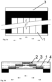
The system of elevator cab and shaft doors for narrowed spaces according to invention will be further explained in the drawings, wherein Figs. 1a) in a front view and 1b) in a top view show the basic arrangement of the invention's mathematical model of 5-panel shaft door having clearance of 600 mm with a central opening.
- Fig.2 shows the realistic optimum arrangement of 5-panel shaft door with clearance of 800 mm in the top view, with central opening relative to the width of the door guide mechanism, with open entrance.
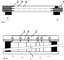
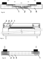
- Figs. 3(a) in a front view and 3(b) in a top view show the extension of the carriage of the closed door guide, and Figs. 3(c) in a front view and 3(d) in a top view show the extension of the carriage of the open door guide according to the invention.
- Fig. 4 shows a distance of 180 mm from the edge of the cabin entrance to the shaft wall, for 800 mm clear width of the entrance, for 5-panel doors with width of the door panel of at least 160 mm. Figure 5(a) shows the existing door guide solution with the guide element maximally extended according to door panel size.
- Fig. 5(b) shows the solution for the door guide with offset guide element according to invention.
- Fig. 6 shows, in a top view, the basic general arrangement of the invention's mathematical model of the closed and open 5-panel shaft door with central opening.
Examples of embodiments
-
It is understood that the various embodiments of the invention are presented by way of illustration and not as limitations of the solutions. Those skilled in the art will find or be able to find, using no more than routine experimentation, many equivalents to specific embodiments of the invention. Such equivalents will also fall within the scope of the patent claims.
Example 1
-
In this example of a particular embodiment of the elevator cab and shaft door system for narrowed spaces according to invention, the construction described is aimed at achieving the smallest possible width of the door guide mechanism 3 to the clear width of 5-panel door with central opening of the door panels as shown in Fig. 1a, Fig. 1b, and Fig. 2. The system is formed by five door panels 1 of the door suspended on separate carriages 2 movably mounted on three motion tracks 4 of the door guide, such that one central door panel 1 of the door is mounted in the rear motion track of the door guide, two door side panels 1 are mounted in the front motion track of the door guide and two door central panels 1 are mounted in the middle motion track 4 of the door guide, wherein the width of the door guide mechanism 3 to the clear width of the door, which ranges from 600 to 900 mm, is in the ratio of 1,3 to 1,45.
FIG. 6 shows, in a top view, the general arrangement of the invention of mathematical model of 5-panel central opening shaft door with central opening with ratio of 1.4a of the width of the door guide mechanism 3 to the clear width and door.
Example 2
-
In this example of a particular embodiment of the elevator cab and shaft door system for narrowed spaces according to invention, a construction aimed at achieving the greatest possible stability of the carriage 2 of the door guide mechanism is described. The system is formed by five door panels 1 of the door suspended on separate carriages 2 movably mounted on three movement tracks 4 of the door guide, such that one central door panel 1 of the door is mounted in the rear motion track of the door guide, two side door panels 1 are mounted in the front door track 4 and two centre door panels 1 are mounted in the central door motion track 4, wherein the width of each carriage 2 of the door guide mechanism 3 is greater than the width of each door panel 1 and the number of upper and lower door motion tracks 4 is the same as that shown in Fig. 4 for 800 mm clear width of door entrance with a marked distance of 180 mm of the inside of the door frame from the wall of the elevator shaft.
Example 3
-
In this example of a particular embodiment of the elevator cab and shaft door system for narrowed spaces according to invention, the construction aimed at achieving the greatest possible stability of the carriage 2 and the reliability of the door guide mechanism 3 is described. The system is formed by five door panels 1 of the door suspended on separate carriages 2 movably mounted on three motion tracks 4 of the door guide, such that one central door panel 1 of the door is mounted in the rear motion track 4 of the door guide, two side door panels 1 are mounted in the front door track 4 and two central door panels 1 are mounted in the central door track 4, wherein the width of each carriage 2 of the door mechanism 3 is greater than the width of each door panel 1 and the number of upper and lower door tracks 4 is the same. Also, the guide element 5 on one side of the carriage 2 of the door guide mechanism 3 is offset from the outer edge of the door panel by more than 35 mm as shown in FIG. 5b as opposed to the state of the art shown in FIG. 5a.
Example 4
-
In this example of a particular embodiment of the elevator cab and shaft door system for narrowed spaces according to invention, the construction described is aimed at achieving the smallest possible width of the door guide mechanism 3 to the clear width of 5-panel door with central opening of the door panels and at achieving the greatest possible stability of the carriage 2 of the door guide mechanism 3. The system is formed by five door panels 1 of the door suspended on separate carriages 2 movably mounted on the three motion tracks 4 of the door guide, so that one central door panel 1 of the door is mounted in the rear motion track 4 of the door guide, two side panels 1 of the door are mounted in the front motion track 4 of the door guide and two central panels 1 of the door are mounted in the central motion track 4 of the door guide, wherein the width of the door guide mechanism 3 to the clear width of the door, which ranges from 600 to 900 mm, is in the ratio of 1,3 to 1,45.
-
Also, the width of each carriage 2 of the door guide mechanism is greater than the width of each door panel 1 and the number of upper and lower motion tracks 4 of the door guide is the same, as shown in Fig. 1b and Fig. 2.
Example 5
-
In this example of a particular embodiment of the elevator cab and shaft door system for narrowed spaces according to invention, the construction described is aimed at achieving the smallest possible width of the door guide mechanism 3 to the clear width of 5-panel door with central opening of the door panels and at achieving the greatest possible stability of the carriage 2 and reliability of the door guide mechanism 3. The system is formed by five door panels 1 of the door suspended on separate carriages 2 movably mounted on the three movement tracks 4 of the door guide, so that one central door panel 1 of the door is mounted in the rear motion track 4 of the door guide, two side panels 1 of the door are mounted in the front motion track 4 of the door guide and two central panels 1 of the door are mounted in the central motion track 4 of the door guide, wherein the width of the door guide mechanism 3 to the clear width of the door, which ranges from 600 to 900 mm, is in the ratio of 1,3 to 1,45. Also, the width of each carriage 2 of the door guide mechanism 3 is greater than the width of each door panel 1, and the number of upper and lower motion tracks 4 of the door guide is the same. At the same time, the guide element 5 on one side of the carriage 2 of the door guide mechanism 3 is offset from the outer edge of the door panel by more than 35 mm, as shown in FIG. 3a and FIG. 3c.
Industrial applicability
-
The system of elevator cab and shaft doors for narrowed spaces according to invention is applicable for automatic elevator doors, also for other automatic sliding doors. The main use is in existing elevator shafts with restricted widths, where the concept will allow the use of large door clear widths and at the same time, despite the narrower door panels, will allow the use of door sliding carriages wider than the door panels as no panels will meet each other on contact as the middle panel is only one and is in a separate rear row. Wider carriages will provide higher reliability and more favourable mechanical stresses. Wider carriages will also provide the option of adjustability of door panel position, which, in the case of adjustable door frame position, will allow one door to be used for a certain range of door clear widths.