EP4382295A1 - Laminating system - Google Patents
Laminating system Download PDFInfo
- Publication number
- EP4382295A1 EP4382295A1 EP23214321.4A EP23214321A EP4382295A1 EP 4382295 A1 EP4382295 A1 EP 4382295A1 EP 23214321 A EP23214321 A EP 23214321A EP 4382295 A1 EP4382295 A1 EP 4382295A1
- Authority
- EP
- European Patent Office
- Prior art keywords
- sheet
- laminating system
- laminate
- fixing device
- ply
- Prior art date
- Legal status (The legal status is an assumption and is not a legal conclusion. Google has not performed a legal analysis and makes no representation as to the accuracy of the status listed.)
- Granted
Links
Images










Classifications
-
- B—PERFORMING OPERATIONS; TRANSPORTING
- B32—LAYERED PRODUCTS
- B32B—LAYERED PRODUCTS, i.e. PRODUCTS BUILT-UP OF STRATA OF FLAT OR NON-FLAT, e.g. CELLULAR OR HONEYCOMB, FORM
- B32B37/00—Methods or apparatus for laminating, e.g. by curing or by ultrasonic bonding
- B32B37/0046—Methods or apparatus for laminating, e.g. by curing or by ultrasonic bonding characterised by constructional aspects of the apparatus
- B32B37/0053—Constructional details of laminating machines comprising rollers; Constructional features of the rollers
-
- B—PERFORMING OPERATIONS; TRANSPORTING
- B32—LAYERED PRODUCTS
- B32B—LAYERED PRODUCTS, i.e. PRODUCTS BUILT-UP OF STRATA OF FLAT OR NON-FLAT, e.g. CELLULAR OR HONEYCOMB, FORM
- B32B37/00—Methods or apparatus for laminating, e.g. by curing or by ultrasonic bonding
- B32B37/14—Methods or apparatus for laminating, e.g. by curing or by ultrasonic bonding characterised by the properties of the layers
- B32B37/16—Methods or apparatus for laminating, e.g. by curing or by ultrasonic bonding characterised by the properties of the layers with all layers existing as coherent layers before laminating
- B32B37/18—Methods or apparatus for laminating, e.g. by curing or by ultrasonic bonding characterised by the properties of the layers with all layers existing as coherent layers before laminating involving the assembly of discrete sheets or panels only
- B32B37/182—Methods or apparatus for laminating, e.g. by curing or by ultrasonic bonding characterised by the properties of the layers with all layers existing as coherent layers before laminating involving the assembly of discrete sheets or panels only one or more of the layers being plastic
- B32B37/185—Laminating sheets, panels or inserts between two discrete plastic layers
-
- B—PERFORMING OPERATIONS; TRANSPORTING
- B32—LAYERED PRODUCTS
- B32B—LAYERED PRODUCTS, i.e. PRODUCTS BUILT-UP OF STRATA OF FLAT OR NON-FLAT, e.g. CELLULAR OR HONEYCOMB, FORM
- B32B38/00—Ancillary operations in connection with laminating processes
- B32B38/18—Handling of layers or the laminate
-
- B—PERFORMING OPERATIONS; TRANSPORTING
- B32—LAYERED PRODUCTS
- B32B—LAYERED PRODUCTS, i.e. PRODUCTS BUILT-UP OF STRATA OF FLAT OR NON-FLAT, e.g. CELLULAR OR HONEYCOMB, FORM
- B32B37/00—Methods or apparatus for laminating, e.g. by curing or by ultrasonic bonding
- B32B37/0046—Methods or apparatus for laminating, e.g. by curing or by ultrasonic bonding characterised by constructional aspects of the apparatus
- B32B2037/0061—Methods or apparatus for laminating, e.g. by curing or by ultrasonic bonding characterised by constructional aspects of the apparatus the apparatus being an office laminator
-
- B—PERFORMING OPERATIONS; TRANSPORTING
- B32—LAYERED PRODUCTS
- B32B—LAYERED PRODUCTS, i.e. PRODUCTS BUILT-UP OF STRATA OF FLAT OR NON-FLAT, e.g. CELLULAR OR HONEYCOMB, FORM
- B32B2250/00—Layers arrangement
- B32B2250/03—3 layers
-
- B—PERFORMING OPERATIONS; TRANSPORTING
- B32—LAYERED PRODUCTS
- B32B—LAYERED PRODUCTS, i.e. PRODUCTS BUILT-UP OF STRATA OF FLAT OR NON-FLAT, e.g. CELLULAR OR HONEYCOMB, FORM
- B32B2250/00—Layers arrangement
- B32B2250/40—Symmetrical or sandwich layers, e.g. ABA, ABCBA, ABCCBA
-
- B—PERFORMING OPERATIONS; TRANSPORTING
- B32—LAYERED PRODUCTS
- B32B—LAYERED PRODUCTS, i.e. PRODUCTS BUILT-UP OF STRATA OF FLAT OR NON-FLAT, e.g. CELLULAR OR HONEYCOMB, FORM
- B32B2255/00—Coating on the layer surface
- B32B2255/12—Coating on the layer surface on paper layer
-
- B—PERFORMING OPERATIONS; TRANSPORTING
- B32—LAYERED PRODUCTS
- B32B—LAYERED PRODUCTS, i.e. PRODUCTS BUILT-UP OF STRATA OF FLAT OR NON-FLAT, e.g. CELLULAR OR HONEYCOMB, FORM
- B32B2260/00—Layered product comprising an impregnated, embedded, or bonded layer wherein the layer comprises an impregnation, embedding, or binder material
- B32B2260/02—Composition of the impregnated, bonded or embedded layer
- B32B2260/028—Paper layer
-
- B—PERFORMING OPERATIONS; TRANSPORTING
- B32—LAYERED PRODUCTS
- B32B—LAYERED PRODUCTS, i.e. PRODUCTS BUILT-UP OF STRATA OF FLAT OR NON-FLAT, e.g. CELLULAR OR HONEYCOMB, FORM
- B32B2260/00—Layered product comprising an impregnated, embedded, or bonded layer wherein the layer comprises an impregnation, embedding, or binder material
- B32B2260/04—Impregnation, embedding, or binder material
- B32B2260/046—Synthetic resin
-
- B—PERFORMING OPERATIONS; TRANSPORTING
- B32—LAYERED PRODUCTS
- B32B—LAYERED PRODUCTS, i.e. PRODUCTS BUILT-UP OF STRATA OF FLAT OR NON-FLAT, e.g. CELLULAR OR HONEYCOMB, FORM
- B32B37/00—Methods or apparatus for laminating, e.g. by curing or by ultrasonic bonding
- B32B37/06—Methods or apparatus for laminating, e.g. by curing or by ultrasonic bonding characterised by the heating method
-
- B—PERFORMING OPERATIONS; TRANSPORTING
- B32—LAYERED PRODUCTS
- B32B—LAYERED PRODUCTS, i.e. PRODUCTS BUILT-UP OF STRATA OF FLAT OR NON-FLAT, e.g. CELLULAR OR HONEYCOMB, FORM
- B32B37/00—Methods or apparatus for laminating, e.g. by curing or by ultrasonic bonding
- B32B37/10—Methods or apparatus for laminating, e.g. by curing or by ultrasonic bonding characterised by the pressing technique, e.g. using action of vacuum or fluid pressure
-
- B—PERFORMING OPERATIONS; TRANSPORTING
- B32—LAYERED PRODUCTS
- B32B—LAYERED PRODUCTS, i.e. PRODUCTS BUILT-UP OF STRATA OF FLAT OR NON-FLAT, e.g. CELLULAR OR HONEYCOMB, FORM
- B32B37/00—Methods or apparatus for laminating, e.g. by curing or by ultrasonic bonding
- B32B37/12—Methods or apparatus for laminating, e.g. by curing or by ultrasonic bonding characterised by using adhesives
-
- B—PERFORMING OPERATIONS; TRANSPORTING
- B32—LAYERED PRODUCTS
- B32B—LAYERED PRODUCTS, i.e. PRODUCTS BUILT-UP OF STRATA OF FLAT OR NON-FLAT, e.g. CELLULAR OR HONEYCOMB, FORM
- B32B37/00—Methods or apparatus for laminating, e.g. by curing or by ultrasonic bonding
- B32B37/30—Partial laminating
Definitions
- Embodiments of the present disclosure relate to a laminating system.
- a technique called lamination processing in which an inner sheet (paper, photo, etc.) is inserted into a two-ply sheet (laminate sheet or lamination film) in which two sheets are overlapped and joined (coupled) on one side and heat and pressure are applied to bond the two-ply sheet, is known.
- Japanese Unexamined Patent Application Publication No. 2022-138826 discloses a sheet separating device in which a two-ply sheet is wrapped around a rotating member and a wrapping circumference difference is generated between an inner peripheral sheet and an outer peripheral sheet based on a geometric relation, thereby separating the two sheets of the two-ply sheet.
- This sheet separating device can reliably separate the two sheets of the two-ply sheet from each other without making the device complicated and large.
- Japanese Unexamined Patent Application Publication No. 2022-138826 discloses a laminating apparatus including the sheet separating device and a heat pressing member (fixing device) that can heat and press a two-ply sheet.
- the laminating apparatus has a disadvantage that the lateral width (footprint) is large because the heat pressing member (fixing device) is horizontally disposed on a downstream side in a conveyance direction of the sheet separating device (see FIG. 29 of Japanese Unexamined Patent Application Publication No. 2022-138826 ).
- Japanese Unexamined Patent Application Publication No. 2022-138826 discloses a configuration in which a sheet separating device and a heat pressing member (fixing device) are disposed vertically and a two-ply sheet is conveyed in a vertical direction (see FIG. 32 of Japanese Unexamined Patent Application Publication No. 2022-138826 ).
- the heat source fixing device
- the heat of the fixing device moves upward and affects the sheet separating device and the driving member around the sheet separating device.
- a laminating system sandwiches a sheet medium in a two-ply sheet in which two sheets are overlapped and partially joined together and applies heat and pressure to bond the two-ply sheet.
- the laminating system includes a sheet separating device, a laminate-fixing device, and a conveyor.
- the sheet separating device separates the two sheets of the two-ply sheet and sandwiches the sheet medium between the two sheets.
- the laminate-fixing device heats and presses the two-ply sheet sandwiching the sheet medium.
- the conveyor conveys the two-ply sheet sandwiching the sheet medium from the sheet separating device to the laminate-fixing device.
- the laminate-fixing device is disposed above the sheet separating device.
- the laminate-fixing device is disposed above the sheet separating device, and thus, the lateral width (footprint) can be reduced.
- the heat of the laminate-fixing device mainly moves upward, and thus, the thermal influence on the sheet separating device can be reduced.
- FIG. 1 is a front view illustrating a configuration of a laminating system according to one embodiment of the present disclosure
- FIG. 2 is a top plan view of the laminating system of FIG. 1
- a laminating system 200 of the present embodiment has a configuration in which a series of operations including feeding and separating of a two-ply sheet (hereinafter referred to as sheet S), insertion of an inner sheet P, and lamination processing by heat pressing can be performed by one apparatus. This series of operations is carried out automatically without any aid of a user, and thus, convenience can be improved over a known technique.
- the sheet S is a two-ply sheet in which two sheets are overlapped and bonded together at a portion (or a side) of the two-ply sheet.
- a first side of the two-ply sheet serves as a transparent sheet such as a transparent polyester sheet
- a second side of the two-ply sheet serves as a transparent or opaque sheet and is disposed facing the first side, and the first and second sides are bonded at one side of the two-ply sheet.
- the two-ply sheet also includes a lamination film.
- the inner sheet P is an example of sheet media inserted into the two-ply sheet.
- sheet media include cardboard, postcard, envelope, thin paper, coated paper (coating paper, art paper, etc.), tracing paper, an overhead projector (OHP) sheet, etc.
- the laminating system 200 includes a sheet feeder 202 that feeds the sheet S, a sheet separating device 203 that separates the sheet S, and an inner sheet feeder 204 that feeds an inner sheet P to be inserted into the separated sheet S.
- the laminating system 200 further includes a laminate-fixing device 205 that bonds the sheet S into which the inner sheet P has been inserted (hereinafter referred to as sheet Sp) by heat pressing, a conveyor 206 that conveys the sheet Sp from the sheet separating device 203 to the laminate-fixing device 205, and an output section 207 to which the bonded sheet Sp is ejected.
- the laminate-fixing device 205 is disposed above the sheet separating device 203.
- the conveyor 206 disposed on the downstream side in the conveyance direction of the sheet separating device 203 includes a first branch conveyance path 212 that reverses the sheet Sp by 180° and conveys the sheet Sp to the laminate-fixing device 205. Therefore, a conveyance direction B of the laminate-fixing device 205 is opposite to a conveyance direction A of the sheet separating device 203.
- the sheet feeder 202 includes a reverse path 202a that reverses and conveys the sheet S.
- the output section 207 is arranged side by side with the laminate-fixing device 205 in the horizontal direction on the downstream side in the conveyance direction of the laminate-fixing device 205. At least a part of the output section 207 is disposed above the sheet separating device 203.
- the inner sheet feeder 204 that conveys the inner sheet P to the sheet separating device 203 is disposed in the horizontal direction with respect to the sheet separating device 203 on the upstream side in the conveyance direction of the sheet separating device 203.
- FIG. 3 is a front view illustrating a configuration of a laminating system in which a laminate-fixing device is disposed in a horizontal direction on a downstream side in a conveyance direction of a sheet separating device.
- elements identical to those illustrated in FIGS. 1 and 2 are given identical reference numerals, and the detailed descriptions thereof are omitted.
- a laminating system 300 of FIG. 3 is provided with a conveyor 306, a laminate-fixing device 305, and an output section 307 in order in the horizontal direction on the downstream side in the conveyance direction of the sheet separating device 203.
- a space (5W) that is about 5 times the length (W) of the horizontal conveyance path of the sheet separating device 203 is required.
- the laminating system 300 is a tabletop type and the horizontal conveyance path (W) of the sheet separating device 203 is 300 mm, the total length of the horizontal conveyance path of the laminating system 300 reaches 1500 mm. This is assumed to be inconvenient to use on a general work machine.
- the laminate-fixing device 205 is disposed above the sheet separating device 203, and the conveyance path of the laminate-fixing device 205 with respect to the sheet separating device 203 is reversed and disposed parallel to the height direction. Therefore, the lateral width (footprint) of the entire device can be reduced.
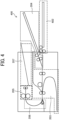
- FIGS. 4 and 5 are each a front view of a laminating system according to a modification of the embodiment of the present disclosure.
- elements identical to those illustrated in FIGS. 1 and 2 are given identical reference numerals, and the detailed descriptions thereof are omitted.
- a laminating system 400 of FIG. 4 includes a sheet feeder 402 coupled in the horizontal direction on the upstream side in the conveyance direction of the sheet separating device 203.
- the overall length of the horizontal conveyance path is slightly larger than that of the laminating system 200 of FIG. 1 , but there is an advantage that the length can be reduced in the height direction.
- a laminating system 500 of FIG. 5 includes a sheet feeder 502 that is conveyed from a position one step lower in the height direction and coupled on the upstream side in the conveyance direction of the sheet separating device 203.
- a sheet feeder 502 that is conveyed from a position one step lower in the height direction and coupled on the upstream side in the conveyance direction of the sheet separating device 203.
- the sheet S laminate sheet or lamination film
- the sheet S has a face, which serves as an upper face in a case where the sheet S is placed flat, as a front surface. In such a case, when either one of both faces is set and conveyed as the upper face, the quality of the ejected sheet is not affected.
- the conveyance direction is restricted.
- the sheet S is conveyed in the conveyance direction A with the joined one side as a head. Therefore, as illustrated in FIG. 1 , when the sheet feeder 202 is disposed below the sheet separating device 203 and the sheet S is reversed and conveyed, the sheet S is stacked on the "right side" with the joint as the head.
- the sheet S is stacked on the "left side" with the joint as the tail.
- the present applicant has filed an application for a technique of separating the sheet S (a two-ply sheet (sheet S) is wrapped around a rotating member, and a wrapping circumference difference is generated between an inner peripheral sheet and an outer peripheral sheet based on a geometrical relation, and thus, the two sheets of the two-ply sheet are separated) as Japanese Unexamined Patent Application Publication No. 2020-121868 .
- a technique of separating the sheet S a two-ply sheet (sheet S) is wrapped around a rotating member, and a wrapping circumference difference is generated between an inner peripheral sheet and an outer peripheral sheet based on a geometrical relation, and thus, the two sheets of the two-ply sheet are separated
- FIG. 6 is a configuration diagram (part 1) illustrating main parts of the laminating system illustrated in FIGS. 1 and 2 .
- the sheet separating device 203 includes an entrance roller pair 108, a wrapping roller 109 as a rotating member, an exit roller pair 113, and the like.
- Each of the entrance roller pair 108 and the exit roller pair 113 is, for example, two rollers paired with each other and is rotationally driven by a driving means (such as a motor).
- the entrance roller pair 108 is rotationally driven in one direction
- the exit roller pair 113 is rotationally driven in forward and reverse directions to nip and convey the sheet S and the inner sheet P.
- the exit roller pair 113 can convey the nipped sheet S toward the downstream side in the conveyance direction, and can also convey the sheet S toward the wrapping roller 109 in the opposite direction (pulling direction).
- the wrapping roller 109 between the entrance roller pair 108 and the exit roller pair 113 is rotationally driven in forward and reverse directions by a driving means (motor or the like), and the rotation thereof can be switched in both directions (clockwise/counterclockwise).
- a driving means motor or the like
- the sheet separating device 203 includes a first separator 214 and a second separator 215 which guide the two separated sheets respectively and separate the two separated sheets vertically from each other.
- the second separator 215 below the first separator 214 has a reverse path 215a, and the first separator 214 and the second separator 215 guide one sheet in different guiding directions.
- the second separator 215 guides the leading end of the sheet to the outside of the device.
- the conveyor 206 includes a first branch conveyance path 212, a second branch conveyance path 213, and a bifurcating claw 208 that switches to one of the first branch conveyance path 212 and the second branch conveyance path 213.
- the first branch conveyance path 212 is coupled to the laminate-fixing device 205 via the reverse path 212a.
- the second branch conveyance path 213 has a switchback path 213a and guides the leading end of the conveyed sheet S to the outside of the device.
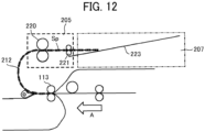
- FIGS. 7 to 12 elements identical to those illustrated in FIG. 6 are given identical reference numerals, and the detailed descriptions thereof are omitted.
- the sheet S from the sheet feeder 202 (see FIG. 1 ) is conveyed in the conveyance direction A, and a part (joint) of the joined two sheets reaches a nip member of the exit roller pair 113.
- the laminating system 200 switches the bifurcating claw 208 of the conveyor 206 and conveys the sheet S toward the second branch conveyance path 213.
- the laminating system 200 guides the leading end (joint) of the sheet S to the outside of the device from an opening 206a disposed in the exterior of the conveyor 206, and nips the tail end of the sheet S by the exit roller pair 113.
- the leading end of the sheet S has not yet been subjected to the lamination processing (heat fixing processing), and thus, the leading end is not stiff and hangs down in the vertical direction by gravity.
- the laminating system 200 reversely rotates (counterclockwise) the exit roller pair 113 to convey the sheet S toward the wrapping roller 109 in a direction opposite to the conveyance direction A.
- the sheet S is wrapped around the wrapping roller 109, and the two sheets of the sheet S are separated.
- Japanese Unexamined Patent Application Publication No. 2020-121868 paragraphs [0039] to [0053]).
- the second branch conveyance path 213 of the conveyor 206 is a so-called switchback path that temporarily accommodates the conveyed sheet S and conveys an end (open end) of the sheet S which is not joined to the sheet separating device.
- the leading end of the conveyed sheet S is to be guided to the outside of the device, it is not necessary to separately provide a conveyance path in the conveyor 206, and the lateral width (footprint) of the device can be further reduced.
- one sheet Sa is conveyed to the first separator 214 and the other sheet Sb is conveyed to the second separator 215 in the direction B opposite to the conveyance direction A by the exit roller pair 113. Therefore, the sheet S is largely opened into the two sheets.
- the conveyance speeds of the sheets Sa and Sb conveyed to the first separator 214 and the second separator 215 are the same, and therefore the conveyance amounts thereof are also the same.
- the second separator 215 guides the leading end of the sheet Sb to the outside of the device, it is not necessary to separately provide a conveyance path in the conveyor 206 (lateral width reduction of the device).
- the laminating system 200 rotates the entrance roller pair 108 to convey the inner sheet P conveyed from the inner sheet feeder 204 (see FIG. 1 ) toward the exit roller pair 113 in the conveyance direction A.
- the inner sheet P is inserted into the sheet S in a manner of abutting against the joint.
- the laminating system 200 rotates the exit roller pair 113 clockwise to merge the sheet S and the inner sheet P, and inserts the inner sheet P into the opened sheet S.
- the laminating system 200 switches the bifurcating claw 208 of the conveyor 206 and conveys the sheet S (sheet Sp), into which the inner sheet P is inserted, toward the first branch conveyance path 212.
- the sheet Sp passes through the first branch conveyance path 212 which is a reverse path and is conveyed to the laminate-fixing device 205.
- the sheet Sp is heated and pressed by a heat pressing roller pair 220 included in the laminate-fixing device 205.
- a heat pressing roller pair 220 included in the laminate-fixing device 205 When the two-ply sheet is a lamination film, an adhesive (made of EVA) applied to the inside of the film reaches a melting point and melts. Subsequently, the sheet Sp is conveyed to the output section 207 via an ejection roller pair 221.
- the sheet Sp heated to a high temperature is pulled by the ejection roller pair 221 having a linear velocity faster than that of the heat pressing roller pair 220, so that curl generated in the sheet Sp can be suppressed.
- the heat accumulated in the sheet Sp is released to the atmosphere, and the temperature of the sheet Sp decreases.
- the adhesives of the two films are bonded to each other and integrated with the inserted inner sheet.
- the output section 207 includes, for example, a sheet ejection tray 223 which is inclined and exposed to the outside of the machine, and the sheet Sp is ejected onto the sheet ejection tray 223. Therefore, the user can take out the sheet Sp as it is from the sheet ejection tray 223.
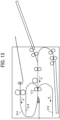
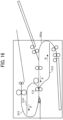
- FIGS. 13 to 16 are front views (No. 1 to 4) illustrating various embodiments of the sheet separating device. The following four patterns are considered as guide paths of the first separator 214 and the second separator 215 disposed in the sheet separating device 203.
- the first separator 214 and the second separator 215 each have a guide path that reverses the separated sheet S from the nip member of the exit roller pair 113 and guides the sheet S in the same direction as the conveyance direction A. That is, the first separator 214 and the second separator 215 are to guide the respective sheets (Sa, Sb) in the same direction (conveyance direction A).
- the first branch conveyance path 212 of the conveyor 206 is disposed in a detour so as not to interfere with the leading end of the first separator 214. Therefore, when corresponding to a larger sheet size (for example, A4 size (sheet length: 303 mm)), the entire device is expanded in the left direction in the drawing.
- a larger sheet size for example, A4 size (sheet length: 303 mm)
- the first separator 214 and the second separator 215 each have a guide path that guides the separated sheet S from the nip member of the exit roller pair 113 in the direction B opposite to the conveyance direction A. That is, the first separator 214 and the second separator 215 are to guide the respective sheets (Sa, Sb) in the same direction (conveyance direction B).
- the reverse path 202a of the sheet feeder 202 is detoured so as not to interfere with the leading end of the second separator 215. Therefore, when corresponding to a larger sheet size, the entire device is expanded in the right direction in the drawing.
- the first separator 214 has a guide path that guides one of the separated sheets S from the nip member of the exit roller pair 113 in the direction B opposite to the conveyance direction A.
- the second separator 215 has a guide path that reverses the other sheet from the nip member of the exit roller pair 113 and guides the other sheet in the same direction as the conveyance direction A. That is, the first separator 214 and the second separator 215 are to guide the respective sheets in opposite directions.
- This configuration is the same as that of the embodiment illustrated in FIG. 1 , and the first separator 214 can secure a guide path for temporarily accommodating one of the separated sheets S without interfering with other conveyance paths.
- the second separator 215 guides the leading end of the other sheet to the outside of the device, a guide path for temporarily accommodating the other sheet can be secured. Therefore, it is possible to cope with a sheet size that is large to some extent without expanding the device size.
- the first separator 214 has a guide path that reverses one of the separated sheets S from the nip member of the exit roller pair 113 and guides the separated sheet S in the same direction as the conveyance direction A.
- the second separator 215 has a guide path that guides the other sheet from the nip member of the exit roller pair 113 in the direction B opposite to the conveyance direction A. That is, the first separator 214 and the second separator 215 are to guide the respective sheets in opposite directions.
- both the first separator 214 and the second separator 215 are expanded on both sides in the width direction of the device so that the leading ends do not interfere with other conveyance paths.
- both the first separator 214 and the second separator 215 are completely accommodated in the device, and the sheet to be guided by each of the first separator 214 and the second separator 215 is also in the device. Therefore, the sheet is not exposed to the outside of the device until the lamination processing is completed, and the sheet can be prevented from being externally affected such as being touched by a user or the like.
- FIG. 17 is a front view of a laminating apparatus according to a comparative example having a vertical conveyance (vertically downward) path.
- a laminating apparatus 600 according to the comparative example a configuration having a vertical conveyance path which is vertically downward after a sheet separating device 603 is known.
- the sheet S is fed from a sheet feeder 602, and the inner sheet P is fed from an inner sheet feeder 604.
- the sheet S is separated into two sheets by the sheet separating device 603, and the inner sheet P is inserted into the opening of the sheet S.
- the sheet S into which the inner sheet P has been inserted is thermally fixed by a laminate-fixing device 605 and ejected to an output section 607.
- a conveyor 606 is used to feed the sheet S back to the sheet separating device 603.
- the laminating apparatus 600 includes the sheet separating device 603 and the conveyor 606 above the laminate-fixing device 605, and the conveyance path of the sheet separating device 603 and the conveyance path of the laminate-fixing device 605 are on the same straight line.
- a heater is mounted inside each roller of a heat pressing roller pair 620 disposed in the laminate-fixing device 605. Before the laminate-fixing device 605 receives the sheet, the heater is powered on, and heating of the heater is started.
- the heat pressing roller pair 620 which has been heated not only applies heat to the sheet but also dissipates heat to the upper portion of the machine during idling. Therefore, the temperatures of a conveyance guide plate of the sheet separating device 603 and the conveyor 606 and other drive components may rise.
- the sheet may stick to the surface of the guide plate of the sheet separating device 603 and increase the conveyance resistance, or a drive component such as a gear may be thermally deformed and cause an operation failure.
- FIG. 18 is a front view illustrating a laminating system including a detachable laminate-fixing device
- FIG. 19 is a schematic diagram illustrating a configuration of the laminate-fixing device of FIG. 18 .
- the laminate-fixing device 205 of the present embodiment is disposed above the sheet separating device 203.
- the heat pressing roller pair 220 By heating the heat pressing roller pair 220, even when heat is emitted from the laminate-fixing device 205, the heat moves upward, and thus, it is possible to suppress the thermal influence on other parts (the sheet separating device 203, etc.).
- the laminate-fixing device 205 includes a fixing entrance conveyor 231, a heat pressing roller pair 220, a fixing relay conveyor 233, a sheet ejection roller pair 234, a cover 235, a stay, and the like.
- the fixing entrance conveyor 231 includes an upper and lower pair of a first fixing entrance conveyance member 231a and a second fixing entrance conveyance member 231b
- the heat pressing roller pair 220 includes an upper limit pair of a first heat pressing roller 220a and a second heat pressing roller 220b.
- the fixing relay conveyor 233 includes an upper and lower pair of a first fixing relay conveyance member 233a and a second fixing relay conveyance member 233b
- the sheet ejection roller pair 234 includes an upper and lower pair of a first sheet ejection roller 234a and a second sheet ejection roller 234b.
- the cover 235 includes a pair of a first cover member 235a and a second cover member 235b, and the first and second cover members 235a and 235b are fixed so as to integrally unitize the heat pressing roller pair 220 and the like via a stay.
- FIG. 20 is a schematic diagram (part 1) illustrating a detachment direction of the laminate-fixing device.
- the unitized laminate-fixing device 205 can be removed by being lifted upward in the vertical direction by the user.
- FIG. 21 is a schematic diagram illustrating a positioning configuration of the laminate-fixing device.
- the conveyor 206 that conveys the sheet Sp to the laminate-fixing device 205 is rotatably disposed around a rotational fulcrum 206b, and has a configuration that can be coupled to and released from the laminate-fixing device 205.
- the laminate-fixing device 205 can be disposed at a predetermined position by positioning members 420 and 422 disposed in the sheet separating device 203.
- the conveyor 206 is rotated to release the coupling to the laminate-fixing device 205, and then the laminate-fixing device 205 can be pulled upward.
- the laminate-fixing device 205 when the laminate-fixing device 205 is mounted, the laminate-fixing device 205 may be disposed from above the sheet separating device 203 while being positioned by the positioning members 420 and 422, and then the conveyor 206 may be coupled to the laminate-fixing device 205.
- FIGS. 22 to 24 are schematic diagrams (parts 2 to 4) illustrating the detachment direction of the laminate-fixing device.
- a laminate-fixing device 205' can be pulled out from the front face of the laminating system 200' (the front direction of the paper of FIG. 22 ), or the laminate-fixing device 205" can be pulled out from the left side face of the laminating system 200" (the left direction of the paper of FIG. 23 ).
- the laminate-fixing devices 205' and 205" are as light as possible.
- the laminate-fixing device 205′′′ having a large weight can support and pull out the laminate-fixing device 205′′′ using a supporting member 424 such as a rail.
- a supporting member 424 such as a rail.
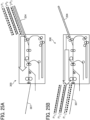
- FIGS. 25A and 25B are schematic diagrams illustrating output results in the laminating system in which the inner sheet is not reversed, wherein FIG. 25A illustrates a stacked state of the inner sheet before feeding, and FIG. 25B illustrates a stacked state of the inner sheet after ejection.
- the laminating system 300 of FIGS. 25A and 25B is the same as that illustrated in FIG. 3 above, and the laminate-fixing device is disposed in the horizontal direction on the downstream side in the conveyance direction of the sheet separating device.
- the inner sheets P stacked on the inner sheet feeder 204 are fed in the order of P 1 , P 2 , and P 3 from the top
- the inner sheets P ejected and stacked on the output section 307 are in the order of P 3 , P 2 , and P 1 from the top, and are in the reverse order of the order before feeding.
- the pages are out of order. This is because the front and back sides of the inner sheet remain as they are at the beginning, and the user changes the page order separately.
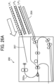
- FIGS. 26A and 26B are schematic diagrams illustrating output results in the laminating system of the present embodiment, wherein FIG. 26A illustrates a stacked state of the inner sheet before feeding, and FIG. 26B illustrates a stacked state of the inner sheet after ejection.
- the inner sheet P is reversed by the reverse path 202a.
- the inner sheets P stacked on the inner sheet feeder 204 are fed in the order of P 1 , P 2 , and P 3 from the top
- the inner sheets P ejected and stacked on the output section 207 are in the order of P 3 , P 2 , and P 1 from the top, which is the same as FIGS. 25A and 25B in that the inner sheets P are in the reverse order of the order before feeding.
- page forward feeding is performed. Therefore, it is not necessary for the user to change the page order, which is advantageous because labor is saved.
- FIG. 27 is a front view (part 2) illustrating a laminating system including a detachable laminate-fixing device.
- a laminating system 700 has a horizontally reversed configuration with respect to the laminating system 200 of FIG. 18 (the same applies to a sheet feeder 702, a sheet separating device 703, an inner sheet feeder 704, a laminate-fixing device 705, an output section 707, and a conveyor 706).
- the feeding direction of the inner sheet P is from left to right when viewed from the front of the drawing.
- the laminate-fixing device 705 can be detached similarly to that illustrated in FIG. 18 .
- a laminating system for sandwiching a sheet medium in a two-ply sheet in which two sheets are overlapped and partially joined together and applying heat and pressure to bond the two-ply sheet.
- the laminating system includes: a sheet separating device to separate the two sheets of the two-ply sheet and sandwich the sheet medium between the two sheets; a laminate-fixing device to heat and press the two-ply sheet sandwiching the sheet medium; and a conveyor to convey the two-ply sheet sandwiching the sheet medium from the sheet separating device to the laminate-fixing device.
- the laminate-fixing device is disposed above the sheet separating device.
- the conveyor includes a first branch conveyance path to reverse and convey the two-ply sheet sandwiching the sheet medium to the laminate-fixing device.
- a conveyance direction of the two-ply sheet in the laminate-fixing device is opposite to a conveyance direction of the two-ply sheet in the sheet separating device.
- the laminating system according to Aspect 1 or 2 further includes an output section disposed downstream from the laminate-fixing device in a conveyance direction of the two-ply sheet in the laminate-fixing device, the output section to receive the two-ply sheet having been laminated by the laminate-fixing device.
- the output section is disposed side by side with the laminate-fixing device in a horizontal direction. At least a part of the output section is disposed above the sheet separating device.
- the laminating system according to any one of Aspects 1 to 3, further including a sheet feeder to convey the two-ply sheet to the sheet separating device.
- the sheet feeder In the laminating system according to Aspect 4, at least a part of the sheet feeder is disposed below the sheet separating device.
- the sheet feeder has a conveyance path to reverse and convey the two-ply sheet.
- the laminating system further includes an inner sheet feeder to convey the sheet medium to the sheet separating device.
- the inner sheet feeder is disposed in a horizontal direction with respect to the sheet separating device on an upstream side in a conveyance direction of the sheet separating device.
- the conveyor includes a second branch conveyance path to temporarily accommodate the two-ply sheet and convey an unjoined end of the two-ply sheet to the sheet separating device.
- the conveyor switches a conveyance path of the two-ply sheet to either the first branch conveyance path or the second branch conveyance path.
- the second branch conveyance path guides a leading end of the two-ply sheet to an outside of the laminating system.
- the sheet separating device includes: a first separator to guide one sheet of the two-ply sheet that has been separated; and a second separator to guide the other sheet of the two-ply sheet.
- the second separator below the first separator has a reverse path, and the first separator and the second separator guide the one sheet and the other sheet of the two-ply sheet in different directions.
- the one sheet and the other sheet of the two-ply sheet that has been separated are guided from a second branch conveyance path to the first separator and the second separator, respectively. Conveyance speeds of the one sheet and the other sheet of the two-ply sheet that has been separated are same.
- the second separator guides a leading end of the other sheet to an outside of the laminating system.
- the laminate-fixing device is detachable from the laminating system.
- the laminate-fixing device includes: a heat pressing roller pair; a cover covering the heat pressing roller pair; and a stay.
- the heat pressing roller pair and the cover are integrated with the stay as a single unit.
- a conveyance path of the laminate-fixing device is located at an uppermost position among conveyance paths in the laminating system, and the laminate-fixing device is detachable upward from the laminating system.
- the present invention can be implemented in any convenient form, for example using dedicated hardware, or a mixture of dedicated hardware and software.
- the present invention may be implemented as computer software implemented by one or more networked processing apparatuses.
- the processing apparatuses include any suitably programmed apparatuses such as a general purpose computer, a personal digital assistant, a Wireless Application Protocol (WAP) or third-generation (3G)-compliant mobile telephone, and so on. Since the present invention can be implemented as software, each and every aspect of the present invention thus encompasses computer software implementable on a programmable device.
- the computer software can be provided to the programmable device using any conventional carrier medium (carrier means).
- the carrier medium includes a transient carrier medium such as an electrical, optical, microwave, acoustic or radio frequency signal carrying the computer code.
- transient medium is a Transmission Control Protocol/Internet Protocol (TCP/IP) signal carrying computer code over an IP network, such as the Internet.
- the carrier medium may also include a storage medium for storing processor readable code such as a floppy disk, a hard disk, a compact disc read-only memory (CD-ROM), a magnetic tape device, or a solid state memory device.
Landscapes
- Sheets, Magazines, And Separation Thereof (AREA)
- Delivering By Means Of Belts And Rollers (AREA)
- Collation Of Sheets And Webs (AREA)
- Registering Or Overturning Sheets (AREA)
- Folding Of Thin Sheet-Like Materials, Special Discharging Devices, And Others (AREA)
- Lining Or Joining Of Plastics Or The Like (AREA)
Abstract
Description
- Embodiments of the present disclosure relate to a laminating system.
- A technique called lamination processing, in which an inner sheet (paper, photo, etc.) is inserted into a two-ply sheet (laminate sheet or lamination film) in which two sheets are overlapped and joined (coupled) on one side and heat and pressure are applied to bond the two-ply sheet, is known.
- For example,
Japanese Unexamined Patent Application Publication No. 2022-138826 - Further,
Japanese Unexamined Patent Application Publication No. 2022-138826 - However, the laminating apparatus has a disadvantage that the lateral width (footprint) is large because the heat pressing member (fixing device) is horizontally disposed on a downstream side in a conveyance direction of the sheet separating device (see FIG. 29 of
Japanese Unexamined Patent Application Publication No. 2022-138826 - Further,
Japanese Unexamined Patent Application Publication No. 2022-138826 Japanese Unexamined Patent Application Publication No. 2022-138826 - In light of the above-described circumstances, an object of the present disclosure is to provide a laminating system that can reduce the lateral width (footprint) and suppress the thermal influence of the fixing device on the sheet separating device.
- According to an aspect of the present disclosure, a laminating system sandwiches a sheet medium in a two-ply sheet in which two sheets are overlapped and partially joined together and applies heat and pressure to bond the two-ply sheet. The laminating system includes a sheet separating device, a laminate-fixing device, and a conveyor. The sheet separating device separates the two sheets of the two-ply sheet and sandwiches the sheet medium between the two sheets. The laminate-fixing device heats and presses the two-ply sheet sandwiching the sheet medium. The conveyor conveys the two-ply sheet sandwiching the sheet medium from the sheet separating device to the laminate-fixing device. The laminate-fixing device is disposed above the sheet separating device.
- In a laminating system according to one aspect of the present disclosure, the laminate-fixing device is disposed above the sheet separating device, and thus, the lateral width (footprint) can be reduced. In addition, the heat of the laminate-fixing device mainly moves upward, and thus, the thermal influence on the sheet separating device can be reduced.
- A more complete appreciation of embodiments of the present disclosure and many of the attendant advantages and features thereof can be readily obtained and understood from the following detailed description with reference to the accompanying drawings, wherein:
-
FIG. 1 is a front view of a laminating system according to one embodiment of the present disclosure; -
FIG. 2 is a top plan view of the laminating system ofFIG. 1 ; -
FIG. 3 is a front view of a laminating system in which a laminate-fixing device is disposed in a horizontal direction on a downstream side in a conveyance direction of a sheet separating device; -
FIG. 4 is a front view (part 1) of a laminating system according to a modification of one embodiment of the present disclosure; -
FIG. 5 is a front view of a laminating system according to another modification of one embodiment of the present disclosure; -
FIG. 6 is a partial view of the laminating system according to one embodiment of the present disclosure; -
FIG. 7 is a partial view of the laminating system following the state illustrated inFIG. 6 ; -
FIG. 8 is a partial view of the laminating system illustrated inFIG. 6 following the state illustrated inFIG. 7 ; -
FIG. 9 is a partial view of the laminating system illustrated inFIG. 6 following the state illustrated inFIG. 8 ; -
FIG. 10 is a partial view of the laminating system illustrated inFIG. 6 following the state illustrated inFIG. 9 ; -
FIG. 11 is a partial view of the laminating system illustrated inFIG. 6 following the state illustrated inFIG. 10 ; -
FIG. 12 is a partial view of the laminating system illustrated inFIG. 6 following the state illustrated inFIG. 11 ; -
FIG. 13 is a front view of the sheet separating device according to one embodiment of the present disclosure; -
FIG. 14 is a front view of the sheet separating device according to one embodiment of the present disclosure; -
FIG. 15 is a front view of the sheet separating device according to one embodiment of the present disclosure; -
FIG. 16 is a front view of the sheet separating device according to one embodiment of the present disclosure; -
FIG. 17 is a front view of a laminating apparatus according to a comparative example having a vertical conveyance (vertically downward) path; -
FIG. 18 is a front view of a laminating system including a detachable laminate-fixing device according to one embodiment of the present disclosure; -
FIG. 19 is a schematic diagram illustrating a configuration of the laminate-fixing device ofFIG. 18 ; -
FIG. 20 is a schematic diagram illustrating a detachment direction of the laminate-fixing device; -
FIG. 21 is a schematic diagram illustrating a positioning configuration of the laminate-fixing device; -
FIG. 22 is a schematic diagram illustrating a detachment direction of the laminate-fixing device; -
FIG. 23 is a schematic diagram illustrating a detachment direction of the laminate-fixing device; -
FIG. 24 is a schematic diagram illustrating a detachment direction of the laminate-fixing device; -
FIG. 25A is a schematic diagram of a laminating system that does not reverse an inner sheet, illustrating a state in which the inner sheet before being fed is stacked; -
FIG. 25B is a schematic diagram of the laminating system illustrated inFIG. 25A , illustrating a state in which an ejected inner sheet is stacked; -
FIGS. 26A and26B are schematic diagrams illustrating an output result in the laminating system according to one embodiment of the present disclosure, andFIG. 26A is a schematic diagram of the laminating system according to one embodiment of the present disclosure, illustrating a state in which the inner sheet before being fed is stacked;FIG. 26B is a schematic diagram of the laminating system illustrated inFIG. 26A , illustrating a state in which the ejected inner sheet is stacked; and -
FIG. 27 is a front view of a laminating system including a detachable laminate-fixing device according to one embodiment of the present disclosure. - The accompanying drawings are intended to depict embodiments of the present disclosure and should not be interpreted to limit the scope thereof. The accompanying drawings are not to be considered as drawn to scale unless explicitly noted. Also, identical or similar reference numerals designate identical or similar components throughout the several views.
- In describing embodiments illustrated in the drawings, specific terminology is employed for the sake of clarity. However, the disclosure of this specification is not intended to be limited to the specific terminology so selected and it is to be understood that each specific element includes all technical equivalents that have a similar function, operate in a similar manner, and achieve a similar result.
- Referring now to the drawings, embodiments of the present disclosure are described below. As used herein, the singular forms "a," "an," and "the" are intended to include the plural forms as well, unless the context clearly indicates otherwise.
-
FIG. 1 is a front view illustrating a configuration of a laminating system according to one embodiment of the present disclosure, andFIG. 2 is a top plan view of the laminating system ofFIG. 1 . Alaminating system 200 of the present embodiment has a configuration in which a series of operations including feeding and separating of a two-ply sheet (hereinafter referred to as sheet S), insertion of an inner sheet P, and lamination processing by heat pressing can be performed by one apparatus. This series of operations is carried out automatically without any aid of a user, and thus, convenience can be improved over a known technique. - Here, the sheet S is a two-ply sheet in which two sheets are overlapped and bonded together at a portion (or a side) of the two-ply sheet. For example, a first side of the two-ply sheet serves as a transparent sheet such as a transparent polyester sheet, a second side of the two-ply sheet serves as a transparent or opaque sheet and is disposed facing the first side, and the first and second sides are bonded at one side of the two-ply sheet. The two-ply sheet also includes a lamination film.
- The inner sheet P is an example of sheet media inserted into the two-ply sheet. In addition to plain paper, sheet media include cardboard, postcard, envelope, thin paper, coated paper (coating paper, art paper, etc.), tracing paper, an overhead projector (OHP) sheet, etc.
- As illustrated in
FIG. 1 , thelaminating system 200 includes asheet feeder 202 that feeds the sheet S, asheet separating device 203 that separates the sheet S, and aninner sheet feeder 204 that feeds an inner sheet P to be inserted into the separated sheet S. Thelaminating system 200 further includes a laminate-fixingdevice 205 that bonds the sheet S into which the inner sheet P has been inserted (hereinafter referred to as sheet Sp) by heat pressing, aconveyor 206 that conveys the sheet Sp from thesheet separating device 203 to the laminate-fixingdevice 205, and anoutput section 207 to which the bonded sheet Sp is ejected. - In the
laminating system 200 of the present embodiment, the laminate-fixingdevice 205 is disposed above thesheet separating device 203. Theconveyor 206 disposed on the downstream side in the conveyance direction of thesheet separating device 203 includes a firstbranch conveyance path 212 that reverses the sheet Sp by 180° and conveys the sheet Sp to the laminate-fixingdevice 205. Therefore, a conveyance direction B of the laminate-fixingdevice 205 is opposite to a conveyance direction A of thesheet separating device 203. - At least a part of the
sheet feeder 202 is disposed below thesheet separating device 203. Thesheet feeder 202 includes areverse path 202a that reverses and conveys the sheet S. - The
output section 207 is arranged side by side with the laminate-fixingdevice 205 in the horizontal direction on the downstream side in the conveyance direction of the laminate-fixingdevice 205. At least a part of theoutput section 207 is disposed above thesheet separating device 203. - The
inner sheet feeder 204 that conveys the inner sheet P to thesheet separating device 203 is disposed in the horizontal direction with respect to thesheet separating device 203 on the upstream side in the conveyance direction of thesheet separating device 203. - Next, advantages of the
laminating system 200 of the present embodiment will be described.FIG. 3 is a front view illustrating a configuration of a laminating system in which a laminate-fixing device is disposed in a horizontal direction on a downstream side in a conveyance direction of a sheet separating device. InFIG. 3 , elements identical to those illustrated inFIGS. 1 and2 are given identical reference numerals, and the detailed descriptions thereof are omitted. - A
laminating system 300 ofFIG. 3 is provided with aconveyor 306, a laminate-fixingdevice 305, and anoutput section 307 in order in the horizontal direction on the downstream side in the conveyance direction of thesheet separating device 203. Thus, in the case of the horizontal conveyance configuration including theinner sheet feeder 204, a space (5W) that is about 5 times the length (W) of the horizontal conveyance path of thesheet separating device 203 is required. - For example, in a case where the
laminating system 300 is a tabletop type and the horizontal conveyance path (W) of thesheet separating device 203 is 300 mm, the total length of the horizontal conveyance path of thelaminating system 300 reaches 1500 mm. This is assumed to be inconvenient to use on a general work machine. - On the other hand, in the
laminating system 200 of the present embodiment, the laminate-fixingdevice 205 is disposed above thesheet separating device 203, and the conveyance path of the laminate-fixingdevice 205 with respect to thesheet separating device 203 is reversed and disposed parallel to the height direction. Therefore, the lateral width (footprint) of the entire device can be reduced. -
FIGS. 4 and5 are each a front view of a laminating system according to a modification of the embodiment of the present disclosure. InFIGS. 4 and5 , elements identical to those illustrated inFIGS. 1 and2 are given identical reference numerals, and the detailed descriptions thereof are omitted. - A
laminating system 400 ofFIG. 4 includes asheet feeder 402 coupled in the horizontal direction on the upstream side in the conveyance direction of thesheet separating device 203. In this case, the overall length of the horizontal conveyance path is slightly larger than that of thelaminating system 200 ofFIG. 1 , but there is an advantage that the length can be reduced in the height direction. - A
laminating system 500 ofFIG. 5 includes asheet feeder 502 that is conveyed from a position one step lower in the height direction and coupled on the upstream side in the conveyance direction of thesheet separating device 203. In this case, there is an advantage that there is almost no difference in the total length of the horizontal conveyance path as compared with thelaminating system 200 ofFIG. 1 and the length in the height direction can be almost equal to that of thelaminating system 400 ofFIG. 4 . - Here, the stacking of the sheet S on the
sheet feeders - Here, the conveyance direction is restricted. In the laminating system of the present embodiment, the sheet S is conveyed in the conveyance direction A with the joined one side as a head. Therefore, as illustrated in
FIG. 1 , when thesheet feeder 202 is disposed below thesheet separating device 203 and the sheet S is reversed and conveyed, the sheet S is stacked on the "right side" with the joint as the head. - On the other hand, as illustrated in
FIGS. 4 and5 , in a case where the conveyance direction of thesheet feeders sheet separating device 203, the sheet S is stacked on the "left side" with the joint as the tail. - Subsequently, a series of operations including feeding and separating of the sheet S, insertion of the inner sheet P, and lamination processing by heat pressing, which are performed by the
laminating system 200 of the present embodiment, will be described. - Here, the present applicant has filed an application for a technique of separating the sheet S (a two-ply sheet (sheet S) is wrapped around a rotating member, and a wrapping circumference difference is generated between an inner peripheral sheet and an outer peripheral sheet based on a geometrical relation, and thus, the two sheets of the two-ply sheet are separated) as
Japanese Unexamined Patent Application Publication No. 2020-121868 -
FIG. 6 is a configuration diagram (part 1) illustrating main parts of the laminating system illustrated inFIGS. 1 and2 . As illustrated inFIG. 6 , thesheet separating device 203 includes anentrance roller pair 108, a wrappingroller 109 as a rotating member, anexit roller pair 113, and the like. Each of theentrance roller pair 108 and theexit roller pair 113 is, for example, two rollers paired with each other and is rotationally driven by a driving means (such as a motor). Theentrance roller pair 108 is rotationally driven in one direction, and theexit roller pair 113 is rotationally driven in forward and reverse directions to nip and convey the sheet S and the inner sheet P. - That is, the
exit roller pair 113 can convey the nipped sheet S toward the downstream side in the conveyance direction, and can also convey the sheet S toward the wrappingroller 109 in the opposite direction (pulling direction). - The wrapping
roller 109 between theentrance roller pair 108 and theexit roller pair 113 is rotationally driven in forward and reverse directions by a driving means (motor or the like), and the rotation thereof can be switched in both directions (clockwise/counterclockwise). - Further, the
sheet separating device 203 includes afirst separator 214 and asecond separator 215 which guide the two separated sheets respectively and separate the two separated sheets vertically from each other. Thesecond separator 215 below thefirst separator 214 has areverse path 215a, and thefirst separator 214 and thesecond separator 215 guide one sheet in different guiding directions. Thesecond separator 215 guides the leading end of the sheet to the outside of the device. - The
conveyor 206 includes a firstbranch conveyance path 212, a secondbranch conveyance path 213, and a bifurcatingclaw 208 that switches to one of the firstbranch conveyance path 212 and the secondbranch conveyance path 213. The firstbranch conveyance path 212 is coupled to the laminate-fixingdevice 205 via thereverse path 212a. On the other hand, the secondbranch conveyance path 213 has aswitchback path 213a and guides the leading end of the conveyed sheet S to the outside of the device. - Subsequently, sheet conveyance of the
laminating system 200 will be described with reference toFIGS. 6 to 12 . InFIGS. 7 to 12 , elements identical to those illustrated inFIG. 6 are given identical reference numerals, and the detailed descriptions thereof are omitted. - In
FIG. 6 , the sheet S from the sheet feeder 202 (seeFIG. 1 ) is conveyed in the conveyance direction A, and a part (joint) of the joined two sheets reaches a nip member of theexit roller pair 113. - Next, in
FIG. 7 , thelaminating system 200 switches the bifurcatingclaw 208 of theconveyor 206 and conveys the sheet S toward the secondbranch conveyance path 213. - Here, as illustrated in
FIG. 8 , thelaminating system 200 guides the leading end (joint) of the sheet S to the outside of the device from anopening 206a disposed in the exterior of theconveyor 206, and nips the tail end of the sheet S by theexit roller pair 113. At this time, the leading end of the sheet S has not yet been subjected to the lamination processing (heat fixing processing), and thus, the leading end is not stiff and hangs down in the vertical direction by gravity. - Subsequently, the
laminating system 200 reversely rotates (counterclockwise) theexit roller pair 113 to convey the sheet S toward the wrappingroller 109 in a direction opposite to the conveyance direction A. Thus, the sheet S is wrapped around the wrappingroller 109, and the two sheets of the sheet S are separated. For a detailed description of this wrapping step, refer toJapanese Unexamined Patent Application Publication No. 2020-121868 - Thus, the second
branch conveyance path 213 of theconveyor 206 is a so-called switchback path that temporarily accommodates the conveyed sheet S and conveys an end (open end) of the sheet S which is not joined to the sheet separating device. In addition, since the leading end of the conveyed sheet S is to be guided to the outside of the device, it is not necessary to separately provide a conveyance path in theconveyor 206, and the lateral width (footprint) of the device can be further reduced. - As illustrated in
FIG. 9 , in the sheet S separated into two sheets, one sheet Sa is conveyed to thefirst separator 214 and the other sheet Sb is conveyed to thesecond separator 215 in the direction B opposite to the conveyance direction A by theexit roller pair 113. Therefore, the sheet S is largely opened into the two sheets. - At this time, the conveyance speeds of the sheets Sa and Sb conveyed to the
first separator 214 and thesecond separator 215 are the same, and therefore the conveyance amounts thereof are also the same. In addition, since thesecond separator 215 guides the leading end of the sheet Sb to the outside of the device, it is not necessary to separately provide a conveyance path in the conveyor 206 (lateral width reduction of the device). - Next, as illustrated in
FIG. 10 , thelaminating system 200 rotates theentrance roller pair 108 to convey the inner sheet P conveyed from the inner sheet feeder 204 (seeFIG. 1 ) toward theexit roller pair 113 in the conveyance direction A. Thus, the inner sheet P is inserted into the sheet S in a manner of abutting against the joint. - Subsequently, as illustrated in
FIG. 11 , thelaminating system 200 rotates theexit roller pair 113 clockwise to merge the sheet S and the inner sheet P, and inserts the inner sheet P into the opened sheet S. At this time, thelaminating system 200 switches the bifurcatingclaw 208 of theconveyor 206 and conveys the sheet S (sheet Sp), into which the inner sheet P is inserted, toward the firstbranch conveyance path 212. - As illustrated in
FIG. 12 , the sheet Sp passes through the firstbranch conveyance path 212 which is a reverse path and is conveyed to the laminate-fixingdevice 205. - The sheet Sp is heated and pressed by a heat pressing
roller pair 220 included in the laminate-fixingdevice 205. When the two-ply sheet is a lamination film, an adhesive (made of EVA) applied to the inside of the film reaches a melting point and melts. Subsequently, the sheet Sp is conveyed to theoutput section 207 via anejection roller pair 221. - The sheet Sp heated to a high temperature is pulled by the
ejection roller pair 221 having a linear velocity faster than that of the heat pressingroller pair 220, so that curl generated in the sheet Sp can be suppressed. - During the conveyance to the
output section 207, the heat accumulated in the sheet Sp is released to the atmosphere, and the temperature of the sheet Sp decreases. When the temperature of the sheet Sp is lowered, the adhesives of the two films are bonded to each other and integrated with the inserted inner sheet. - The
output section 207 includes, for example, asheet ejection tray 223 which is inclined and exposed to the outside of the machine, and the sheet Sp is ejected onto thesheet ejection tray 223. Therefore, the user can take out the sheet Sp as it is from thesheet ejection tray 223. -
FIGS. 13 to 16 are front views (No. 1 to 4) illustrating various embodiments of the sheet separating device. The following four patterns are considered as guide paths of thefirst separator 214 and thesecond separator 215 disposed in thesheet separating device 203. - In
FIG. 13 , thefirst separator 214 and thesecond separator 215 each have a guide path that reverses the separated sheet S from the nip member of theexit roller pair 113 and guides the sheet S in the same direction as the conveyance direction A. That is, thefirst separator 214 and thesecond separator 215 are to guide the respective sheets (Sa, Sb) in the same direction (conveyance direction A). - In this case, the first
branch conveyance path 212 of theconveyor 206 is disposed in a detour so as not to interfere with the leading end of thefirst separator 214. Therefore, when corresponding to a larger sheet size (for example, A4 size (sheet length: 303 mm)), the entire device is expanded in the left direction in the drawing. - In
FIG. 14 , thefirst separator 214 and thesecond separator 215 each have a guide path that guides the separated sheet S from the nip member of theexit roller pair 113 in the direction B opposite to the conveyance direction A. That is, thefirst separator 214 and thesecond separator 215 are to guide the respective sheets (Sa, Sb) in the same direction (conveyance direction B). - In this case, when the
sheet feeder 202 is disposed below the sheet separating device, thereverse path 202a of thesheet feeder 202 is detoured so as not to interfere with the leading end of thesecond separator 215. Therefore, when corresponding to a larger sheet size, the entire device is expanded in the right direction in the drawing. - In
FIG. 15 , thefirst separator 214 has a guide path that guides one of the separated sheets S from the nip member of theexit roller pair 113 in the direction B opposite to the conveyance direction A. On the other hand, thesecond separator 215 has a guide path that reverses the other sheet from the nip member of theexit roller pair 113 and guides the other sheet in the same direction as the conveyance direction A. That is, thefirst separator 214 and thesecond separator 215 are to guide the respective sheets in opposite directions. - This configuration is the same as that of the embodiment illustrated in
FIG. 1 , and thefirst separator 214 can secure a guide path for temporarily accommodating one of the separated sheets S without interfering with other conveyance paths. On the other hand, since thesecond separator 215 guides the leading end of the other sheet to the outside of the device, a guide path for temporarily accommodating the other sheet can be secured. Therefore, it is possible to cope with a sheet size that is large to some extent without expanding the device size. - In
FIG. 16 , thefirst separator 214 has a guide path that reverses one of the separated sheets S from the nip member of theexit roller pair 113 and guides the separated sheet S in the same direction as the conveyance direction A. On the other hand, thesecond separator 215 has a guide path that guides the other sheet from the nip member of theexit roller pair 113 in the direction B opposite to the conveyance direction A. That is, thefirst separator 214 and thesecond separator 215 are to guide the respective sheets in opposite directions. - In this case, both the
first separator 214 and thesecond separator 215 are expanded on both sides in the width direction of the device so that the leading ends do not interfere with other conveyance paths. Here, both thefirst separator 214 and thesecond separator 215 are completely accommodated in the device, and the sheet to be guided by each of thefirst separator 214 and thesecond separator 215 is also in the device. Therefore, the sheet is not exposed to the outside of the device until the lamination processing is completed, and the sheet can be prevented from being externally affected such as being touched by a user or the like. -
FIG. 17 is a front view of a laminating apparatus according to a comparative example having a vertical conveyance (vertically downward) path. As alaminating apparatus 600 according to the comparative example, a configuration having a vertical conveyance path which is vertically downward after asheet separating device 603 is known. - In the
laminating apparatus 600, the sheet S is fed from asheet feeder 602, and the inner sheet P is fed from aninner sheet feeder 604. The sheet S is separated into two sheets by thesheet separating device 603, and the inner sheet P is inserted into the opening of the sheet S. The sheet S into which the inner sheet P has been inserted is thermally fixed by a laminate-fixingdevice 605 and ejected to anoutput section 607. Aconveyor 606 is used to feed the sheet S back to thesheet separating device 603. - Thus, the
laminating apparatus 600 includes thesheet separating device 603 and theconveyor 606 above the laminate-fixingdevice 605, and the conveyance path of thesheet separating device 603 and the conveyance path of the laminate-fixingdevice 605 are on the same straight line. - A heater is mounted inside each roller of a heat pressing
roller pair 620 disposed in the laminate-fixingdevice 605. Before the laminate-fixingdevice 605 receives the sheet, the heater is powered on, and heating of the heater is started. - The heat pressing
roller pair 620 which has been heated not only applies heat to the sheet but also dissipates heat to the upper portion of the machine during idling. Therefore, the temperatures of a conveyance guide plate of thesheet separating device 603 and theconveyor 606 and other drive components may rise. - Specifically, the sheet may stick to the surface of the guide plate of the
sheet separating device 603 and increase the conveyance resistance, or a drive component such as a gear may be thermally deformed and cause an operation failure. -
FIG. 18 is a front view illustrating a laminating system including a detachable laminate-fixing device, andFIG. 19 is a schematic diagram illustrating a configuration of the laminate-fixing device ofFIG. 18 . - The laminate-fixing
device 205 of the present embodiment is disposed above thesheet separating device 203. By heating the heat pressingroller pair 220, even when heat is emitted from the laminate-fixingdevice 205, the heat moves upward, and thus, it is possible to suppress the thermal influence on other parts (thesheet separating device 203, etc.). - As illustrated in
FIG. 19 , the laminate-fixingdevice 205 includes a fixingentrance conveyor 231, a heat pressingroller pair 220, a fixingrelay conveyor 233, a sheetejection roller pair 234, a cover 235, a stay, and the like. - The fixing
entrance conveyor 231 includes an upper and lower pair of a first fixingentrance conveyance member 231a and a second fixingentrance conveyance member 231b, and the heat pressingroller pair 220 includes an upper limit pair of a firstheat pressing roller 220a and a secondheat pressing roller 220b. - Further, the fixing
relay conveyor 233 includes an upper and lower pair of a first fixingrelay conveyance member 233a and a second fixing relay conveyance member 233b, and the sheetejection roller pair 234 includes an upper and lower pair of a firstsheet ejection roller 234a and a secondsheet ejection roller 234b. - Furthermore, the cover 235 includes a pair of a
first cover member 235a and asecond cover member 235b, and the first andsecond cover members roller pair 220 and the like via a stay. - In particular, it is preferable to use a material having a high heat insulating effect for the cover 235 to suppress heat conduction from the heat pressing
roller pair 220 to other members. - Next, a method for detaching the laminate-fixing device will be described.
-
FIG. 20 is a schematic diagram (part 1) illustrating a detachment direction of the laminate-fixing device. For example, as illustrated inFIG. 20 , the unitized laminate-fixingdevice 205 can be removed by being lifted upward in the vertical direction by the user. -
FIG. 21 is a schematic diagram illustrating a positioning configuration of the laminate-fixing device. As illustrated inFIG. 21 , theconveyor 206 that conveys the sheet Sp to the laminate-fixingdevice 205 is rotatably disposed around arotational fulcrum 206b, and has a configuration that can be coupled to and released from the laminate-fixingdevice 205. The laminate-fixingdevice 205 can be disposed at a predetermined position by positioningmembers sheet separating device 203. - Therefore, when the laminate-fixing
device 205 is removed, theconveyor 206 is rotated to release the coupling to the laminate-fixingdevice 205, and then the laminate-fixingdevice 205 can be pulled upward. On the other hand, when the laminate-fixingdevice 205 is mounted, the laminate-fixingdevice 205 may be disposed from above thesheet separating device 203 while being positioned by thepositioning members conveyor 206 may be coupled to the laminate-fixingdevice 205. -
FIGS. 22 to 24 are schematic diagrams (parts 2 to 4) illustrating the detachment direction of the laminate-fixing device. As the detachment direction, a laminate-fixing device 205' can be pulled out from the front face of the laminating system 200' (the front direction of the paper ofFIG. 22 ), or the laminate-fixingdevice 205" can be pulled out from the left side face of thelaminating system 200" (the left direction of the paper ofFIG. 23 ). - However, in consideration of workability, it is preferable that the laminate-fixing
devices 205' and 205" are as light as possible. - On the other hand, in the case of the laminate-fixing
device 205‴ having a large weight, as illustrated inFIG. 24 , the laminate-fixing device can support and pull out the laminate-fixingdevice 205‴ using a supportingmember 424 such as a rail. Thus, even in the laminate-fixingdevice 205‴ having a large weight, workability of detachment can be improved. - Next, an advantageous configuration of the present embodiment will be described.
-
FIGS. 25A and 25B are schematic diagrams illustrating output results in the laminating system in which the inner sheet is not reversed, whereinFIG. 25A illustrates a stacked state of the inner sheet before feeding, andFIG. 25B illustrates a stacked state of the inner sheet after ejection. - The
laminating system 300 ofFIGS. 25A and 25B is the same as that illustrated inFIG. 3 above, and the laminate-fixing device is disposed in the horizontal direction on the downstream side in the conveyance direction of the sheet separating device. - In the
laminating system 300, when the inner sheets P stacked on theinner sheet feeder 204 are fed in the order of P1, P2, and P3 from the top, the inner sheets P ejected and stacked on theoutput section 307 are in the order of P3, P2, and P1 from the top, and are in the reverse order of the order before feeding. Furthermore, in a case where there is information on both faces of the inner sheet P and there is a relation to the page order, the pages are out of order. This is because the front and back sides of the inner sheet remain as they are at the beginning, and the user changes the page order separately. -
FIGS. 26A and26B are schematic diagrams illustrating output results in the laminating system of the present embodiment, whereinFIG. 26A illustrates a stacked state of the inner sheet before feeding, andFIG. 26B illustrates a stacked state of the inner sheet after ejection. - In the
laminating system 200 of the present embodiment, the inner sheet P is reversed by thereverse path 202a. When the inner sheets P stacked on theinner sheet feeder 204 are fed in the order of P1, P2, and P3 from the top, the inner sheets P ejected and stacked on theoutput section 207 are in the order of P3, P2, and P1 from the top, which is the same asFIGS. 25A and 25B in that the inner sheets P are in the reverse order of the order before feeding. However, since the front and back sides of the inner sheet P are reversed, in a case where information is on both faces of the inner sheet P and there is a relation to the page order, page forward feeding is performed. Therefore, it is not necessary for the user to change the page order, which is advantageous because labor is saved. -
FIG. 27 is a front view (part 2) illustrating a laminating system including a detachable laminate-fixing device. Alaminating system 700 has a horizontally reversed configuration with respect to thelaminating system 200 ofFIG. 18 (the same applies to asheet feeder 702, asheet separating device 703, an inner sheet feeder 704, a laminate-fixingdevice 705, anoutput section 707, and a conveyor 706). In this case, the feeding direction of the inner sheet P is from left to right when viewed from the front of the drawing. Even in such a configuration of reverse arrangement, the laminate-fixingdevice 705 can be detached similarly to that illustrated inFIG. 18 . - Although the embodiments of the present disclosure have been described in detail above, the above-described embodiments are examples, and can be used with various modifications in a range of not departing from the gist. For example, embodiments and modifications may be combined with each other.
- Aspects of the present disclosure are, for example, as follows.
- A laminating system for sandwiching a sheet medium in a two-ply sheet in which two sheets are overlapped and partially joined together and applying heat and pressure to bond the two-ply sheet. The laminating system includes: a sheet separating device to separate the two sheets of the two-ply sheet and sandwich the sheet medium between the two sheets; a laminate-fixing device to heat and press the two-ply sheet sandwiching the sheet medium; and a conveyor to convey the two-ply sheet sandwiching the sheet medium from the sheet separating device to the laminate-fixing device. The laminate-fixing device is disposed above the sheet separating device.
- In the laminating system according to Aspect 1, the conveyor includes a first branch conveyance path to reverse and convey the two-ply sheet sandwiching the sheet medium to the laminate-fixing device. A conveyance direction of the two-ply sheet in the laminate-fixing device is opposite to a conveyance direction of the two-ply sheet in the sheet separating device.
- The laminating system according to Aspect 1 or 2 further includes an output section disposed downstream from the laminate-fixing device in a conveyance direction of the two-ply sheet in the laminate-fixing device, the output section to receive the two-ply sheet having been laminated by the laminate-fixing device. The output section is disposed side by side with the laminate-fixing device in a horizontal direction. At least a part of the output section is disposed above the sheet separating device.
- The laminating system according to any one of Aspects 1 to 3, further including a sheet feeder to convey the two-ply sheet to the sheet separating device.
- In the laminating system according to Aspect 4, at least a part of the sheet feeder is disposed below the sheet separating device. The sheet feeder has a conveyance path to reverse and convey the two-ply sheet.
- The laminating system according to any one of Aspects 1 to 5 further includes an inner sheet feeder to convey the sheet medium to the sheet separating device. The inner sheet feeder is disposed in a horizontal direction with respect to the sheet separating device on an upstream side in a conveyance direction of the sheet separating device.
- In the laminating system according to Aspect 2, the conveyor includes a second branch conveyance path to temporarily accommodate the two-ply sheet and convey an unjoined end of the two-ply sheet to the sheet separating device. The conveyor switches a conveyance path of the two-ply sheet to either the first branch conveyance path or the second branch conveyance path.
- In the laminating system according to Aspect 7, the second branch conveyance path guides a leading end of the two-ply sheet to an outside of the laminating system.
- In the laminating system according to any one of Aspects 1 to 8, the sheet separating device includes: a first separator to guide one sheet of the two-ply sheet that has been separated; and a second separator to guide the other sheet of the two-ply sheet.
- In the laminating system according to Aspect 9, the second separator below the first separator has a reverse path, and the first separator and the second separator guide the one sheet and the other sheet of the two-ply sheet in different directions.
- In the laminating system according to Aspect 9 or 10, the one sheet and the other sheet of the two-ply sheet that has been separated are guided from a second branch conveyance path to the first separator and the second separator, respectively. Conveyance speeds of the one sheet and the other sheet of the two-ply sheet that has been separated are same.
- In the laminating system according to any one of Aspects 9 to 11, the second separator guides a leading end of the other sheet to an outside of the laminating system.
- In the laminating system according to any one of Aspects 1 to 12, the laminate-fixing device is detachable from the laminating system.
- In the laminating system according to any one of Aspects 1 to 13, the laminate-fixing device includes: a heat pressing roller pair; a cover covering the heat pressing roller pair; and a stay. The heat pressing roller pair and the cover are integrated with the stay as a single unit.
- In the laminating system according to any one of Aspects 1 to 14, a conveyance path of the laminate-fixing device is located at an uppermost position among conveyance paths in the laminating system, and the laminate-fixing device is detachable upward from the laminating system.
- The present invention can be implemented in any convenient form, for example using dedicated hardware, or a mixture of dedicated hardware and software. The present invention may be implemented as computer software implemented by one or more networked processing apparatuses. The processing apparatuses include any suitably programmed apparatuses such as a general purpose computer, a personal digital assistant, a Wireless Application Protocol (WAP) or third-generation (3G)-compliant mobile telephone, and so on. Since the present invention can be implemented as software, each and every aspect of the present invention thus encompasses computer software implementable on a programmable device. The computer software can be provided to the programmable device using any conventional carrier medium (carrier means). The carrier medium includes a transient carrier medium such as an electrical, optical, microwave, acoustic or radio frequency signal carrying the computer code. An example of such a transient medium is a Transmission Control Protocol/Internet Protocol (TCP/IP) signal carrying computer code over an IP network, such as the Internet. The carrier medium may also include a storage medium for storing processor readable code such as a floppy disk, a hard disk, a compact disc read-only memory (CD-ROM), a magnetic tape device, or a solid state memory device.
Claims (15)
- A laminating system (200) for sandwiching a sheet medium in a two-ply sheet in which two sheets are overlapped and partially joined together and applying heat and pressure to bond the two-ply sheet, the laminating system comprising:a sheet separating device (203, 603, 703) to separate the two sheets of the two-ply sheet and sandwich the sheet medium between the two sheets;a laminate-fixing device (205, 205', 205", 205"', 305, 605, 705) to heat and press the two-ply sheet sandwiching the sheet medium; anda conveyor (206, 306, 606, 706) to convey the two-ply sheet sandwiching the sheet medium from the sheet separating device (203, 603, 703) to the laminate-fixing device (205, 205', 205", 205"', 305, 605, 705),the laminate-fixing device (205, 205', 205", 205"', 305, 605, 705) being disposed above the sheet separating device (203, 603, 703).
- The laminating system according to claim 1,wherein the conveyor (206, 306, 606, 706) includes a branch conveyance path to reverse and convey the two-ply sheet sandwiching the sheet medium to the laminate-fixing device (205, 205', 205", 205"', 305, 605, 705), anda conveyance direction of the two-ply sheet in the laminate-fixing device (205, 205', 205", 205"', 305, 605, 705) is opposite to a conveyance direction of the two-ply sheet in the sheet separating device (203, 603, 703).
- The laminating system according to claim 1 or 2, further comprising:an output section (207, 307, 607, 707) disposed downstream from the laminate-fixing device (205, 205', 205", 205"', 305, 605, 705) in a conveyance direction of the two-ply sheet in the laminate-fixing device (205, 205', 205", 205"', 305, 605, 705), the output section (207, 307, 607, 707) to receive the two-ply sheet having been laminated by the laminate-fixing device (205, 205', 205", 205‴, 305, 605, 705),wherein the output section (207, 307, 607, 707) is disposed side by side with the laminate-fixing device (205, 205', 205", 205"', 305, 605, 705) in a horizontal direction, andat least a part of the output section (207, 307, 607, 707) is disposed above the sheet separating device (203, 603, 703).
- The laminating system according to any one of claims 1 to 3, further comprising a sheet feeder (202, 402, 502, 602, 702) to convey the two-ply sheet to the sheet separating device (203, 603, 703).
- The laminating system according to claim 4,wherein at least a part of the sheet feeder (202, 402, 502, 602, 702) is disposed below the sheet separating device (203, 603, 703), andthe sheet feeder (202, 402, 502, 602, 702) includes a conveyance path to reverse and convey the two-ply sheet.
- The laminating system according to any one of claims 1 to 5, further comprising:an inner sheet feeder (204, 604, 704) to convey the sheet medium to the sheet separating device (203, 603, 703),wherein the inner sheet feeder (204, 604, 704) is disposed in a horizontal direction with respect to the sheet separating device (203, 603, 703) on an upstream side in a conveyance direction of the sheet separating device (203, 603, 703).
- The laminating system according to claim 2,wherein the conveyor (206, 306, 606, 706) includes another branch conveyance path to temporarily accommodate the two-ply sheet and convey an unjoined end of the two-ply sheet to the sheet separating device (203, 603, 703), andthe conveyor (206, 306, 606, 706) switches a conveyance path of the two-ply sheet to either the branch conveyance path or said another branch conveyance path.
- The laminating system according to claim 7,
wherein said another branch conveyance path guides a leading end of the two-ply sheet to an outside of the laminating system. - The laminating system according to any one of claims 1 to 8,
wherein the sheet separating device (203, 603, 703) includes:a first separator to guide one sheet of the two-ply sheet that has been separated; anda second separator to guide the other sheet of the two-ply sheet. - The laminating system according to claim 9,
wherein the second separator below the first separator has a reverse path, and the first separator and the second separator guide the one sheet and the other sheet in different directions. - The laminating system according to claim 9 or 10,
wherein the one sheet and the other sheet of the two-ply sheet that has been separated are guided from another branch conveyance path to the first separator and the second separator, respectively, and conveyance speeds of the one sheet and the other sheet of the two-ply sheet that has been separated are same. - The laminating system according to any one of claims 9 to 11,
wherein the second separator guides a leading end of the other sheet to an outside of the laminating system. - The laminating system according to any one of claims 1 to 12,
wherein the laminate-fixing device (205, 205', 205", 205"', 305, 605, 705) is detachable from the laminating system. - The laminating system according to any one of claims 1 to 13,
wherein the laminate-fixing device (205, 205', 205", 205"', 305, 605, 705) includes:a heat pressing roller pair (220);a cover (235) covering the heat pressing roller pair; anda stay, andthe heat pressing roller pair and the cover are integrated with the stay as a single unit. - The laminating system according to any one of claims 1 to 14,
wherein a conveyance path of the laminate-fixing device (205, 205', 205", 205"', 305, 605, 705) is located at an uppermost position among conveyance paths in the laminating system, and the laminate-fixing device (205, 205', 205", 205"', 305, 605, 705) is detachable upward from the laminating system.
Applications Claiming Priority (1)
| Application Number | Priority Date | Filing Date | Title |
|---|---|---|---|
| JP2022197001A JP2024082846A (en) | 2022-12-09 | 2022-12-09 | Lamination Processing System |
Publications (2)
| Publication Number | Publication Date |
|---|---|
| EP4382295A1 true EP4382295A1 (en) | 2024-06-12 |
| EP4382295B1 EP4382295B1 (en) | 2025-07-23 |
Family
ID=89119635
Family Applications (1)
| Application Number | Title | Priority Date | Filing Date |
|---|---|---|---|
| EP23214321.4A Active EP4382295B1 (en) | 2022-12-09 | 2023-12-05 | Laminating system |
Country Status (3)
| Country | Link |
|---|---|
| US (1) | US12570083B2 (en) |
| EP (1) | EP4382295B1 (en) |
| JP (1) | JP2024082846A (en) |
Cited By (1)
| Publication number | Priority date | Publication date | Assignee | Title |
|---|---|---|---|---|
| CN118876418A (en) * | 2024-07-22 | 2024-11-01 | 苏州裕复利新材料有限公司 | A double-sided film laminating device for flat sheet film material |
Citations (2)
| Publication number | Priority date | Publication date | Assignee | Title |
|---|---|---|---|---|
| JP2020121868A (en) | 2019-01-31 | 2020-08-13 | 株式会社リコー | Sheet peeling apparatus, laminating processing apparatus, image forming apparatus and image forming system |
| JP2022138826A (en) | 2021-03-11 | 2022-09-26 | 株式会社リコー | Sheet processing device, lamination processing device, image forming device and image forming system |
Family Cites Families (7)
| Publication number | Priority date | Publication date | Assignee | Title |
|---|---|---|---|---|
| KR200231988Y1 (en) * | 2001-02-27 | 2001-07-03 | 신일산업 주식회사 | auto roll laminater |
| US11261043B2 (en) * | 2020-05-07 | 2022-03-01 | Ricoh Company, Ltd. | Sheet processing device, sheet laminator, image forming apparatus, and image forming system |
| JP7727167B2 (en) | 2021-04-16 | 2025-08-21 | 株式会社リコー | Sheet processing apparatus, image forming apparatus, and image forming system |
| JP2023095139A (en) | 2021-12-24 | 2023-07-06 | 株式会社リコー | Sheet stacking unit, laminating device, image forming device, and image forming system |
| JP2023095085A (en) | 2021-12-24 | 2023-07-06 | 株式会社リコー | Sheet peeling device, lamination processing device, image forming device, and image forming system |
| CN116339087B (en) | 2021-12-24 | 2025-01-14 | 株式会社理光 | Lamination processing apparatus, image forming apparatus, and image forming system |
| JP7818175B2 (en) | 2022-01-13 | 2026-02-20 | 株式会社リコー | Lamination device, image forming device, and lamination method |
-
2022
- 2022-12-09 JP JP2022197001A patent/JP2024082846A/en active Pending
-
2023
- 2023-12-04 US US18/528,609 patent/US12570083B2/en active Active
- 2023-12-05 EP EP23214321.4A patent/EP4382295B1/en active Active
Patent Citations (2)
| Publication number | Priority date | Publication date | Assignee | Title |
|---|---|---|---|---|
| JP2020121868A (en) | 2019-01-31 | 2020-08-13 | 株式会社リコー | Sheet peeling apparatus, laminating processing apparatus, image forming apparatus and image forming system |
| JP2022138826A (en) | 2021-03-11 | 2022-09-26 | 株式会社リコー | Sheet processing device, lamination processing device, image forming device and image forming system |
Cited By (1)
| Publication number | Priority date | Publication date | Assignee | Title |
|---|---|---|---|---|
| CN118876418A (en) * | 2024-07-22 | 2024-11-01 | 苏州裕复利新材料有限公司 | A double-sided film laminating device for flat sheet film material |
Also Published As
| Publication number | Publication date |
|---|---|
| EP4382295B1 (en) | 2025-07-23 |
| JP2024082846A (en) | 2024-06-20 |
| US12570083B2 (en) | 2026-03-10 |
| US20240190121A1 (en) | 2024-06-13 |
Similar Documents
| Publication | Publication Date | Title |
|---|---|---|
| EP3689607B1 (en) | Sheet separation device, laminator, image forming apparatus, and image forming system | |
| US11273629B2 (en) | Sheet separation device, laminator, image forming apparatus, and image forming system | |
| US20200341414A1 (en) | Sheet separation device, laminator, image forming apparatus, and image forming system | |
| JP5578806B2 (en) | Perfect binding machine and perfect binding method for processing Nakamoto | |
| JP2004209869A (en) | Gluing bookbinding apparatus and image forming system | |
| JP2004209870A (en) | Gluing bookbinding apparatus | |
| EP1752309B1 (en) | Bookbinding apparatus | |
| EP4382295B1 (en) | Laminating system | |
| EP1759870B1 (en) | Bookbinding apparatus and image forming system | |
| JP4255412B2 (en) | Image forming system | |
| JP4382307B2 (en) | Bookbinding apparatus and bookbinding method | |
| JP2005015225A (en) | Image formation system and single sheet processor | |
| JP4382308B2 (en) | Bookbinding apparatus and bookbinding method | |
| JP4027979B2 (en) | Method and apparatus for manufacturing a booklet | |
| JP4760512B2 (en) | Bookbinding equipment | |
| JP4849600B2 (en) | Bookbinding apparatus, bookbinding system, and bookbinding method | |
| JP7459683B2 (en) | Sheet processing equipment, lamination processing equipment, image forming equipment, and image forming systems | |
| JP2003103959A (en) | Bookbinding device | |
| JP2004106976A (en) | Bookbinding device | |
| US12539696B2 (en) | Lamination processing system | |
| JP4349404B2 (en) | Bookbinding system, bookbinding method, and image forming apparatus | |
| JP2009220393A (en) | Laminator for printed photograph | |
| JP2008030298A (en) | Equipment, system and method for bookbinding | |
| JPH1134536A (en) | Bookbinding treatment apparatus | |
| JP4591274B2 (en) | Bookbinding apparatus and image forming system |
Legal Events
| Date | Code | Title | Description |
|---|---|---|---|
| PUAI | Public reference made under article 153(3) epc to a published international application that has entered the european phase |
Free format text: ORIGINAL CODE: 0009012 |
|
| STAA | Information on the status of an ep patent application or granted ep patent |
Free format text: STATUS: REQUEST FOR EXAMINATION WAS MADE |
|
| 17P | Request for examination filed |
Effective date: 20231205 |
|
| AK | Designated contracting states |
Kind code of ref document: A1 Designated state(s): AL AT BE BG CH CY CZ DE DK EE ES FI FR GB GR HR HU IE IS IT LI LT LU LV MC ME MK MT NL NO PL PT RO RS SE SI SK SM TR |
|
| STAA | Information on the status of an ep patent application or granted ep patent |
Free format text: STATUS: EXAMINATION IS IN PROGRESS |
|
| 17Q | First examination report despatched |
Effective date: 20241126 |
|
| GRAP | Despatch of communication of intention to grant a patent |
Free format text: ORIGINAL CODE: EPIDOSNIGR1 |
|
| STAA | Information on the status of an ep patent application or granted ep patent |
Free format text: STATUS: GRANT OF PATENT IS INTENDED |
|
| INTG | Intention to grant announced |
Effective date: 20250325 |
|
| P01 | Opt-out of the competence of the unified patent court (upc) registered |
Free format text: CASE NUMBER: APP_18774/2025 Effective date: 20250417 |
|
| GRAS | Grant fee paid |
Free format text: ORIGINAL CODE: EPIDOSNIGR3 |
|
| GRAA | (expected) grant |
Free format text: ORIGINAL CODE: 0009210 |
|
| STAA | Information on the status of an ep patent application or granted ep patent |
Free format text: STATUS: THE PATENT HAS BEEN GRANTED |
|
| AK | Designated contracting states |
Kind code of ref document: B1 Designated state(s): AL AT BE BG CH CY CZ DE DK EE ES FI FR GB GR HR HU IE IS IT LI LT LU LV MC ME MK MT NL NO PL PT RO RS SE SI SK SM TR |
|
| REG | Reference to a national code |
Ref country code: GB Ref legal event code: FG4D |
|
| REG | Reference to a national code |
Ref country code: CH Ref legal event code: EP |
|
| REG | Reference to a national code |
Ref country code: IE Ref legal event code: FG4D |
|
| REG | Reference to a national code |
Ref country code: DE Ref legal event code: R096 Ref document number: 602023005039 Country of ref document: DE |
|
| REG | Reference to a national code |
Ref country code: NL Ref legal event code: FP |
|
| PG25 | Lapsed in a contracting state [announced via postgrant information from national office to epo] |
Ref country code: PT Free format text: LAPSE BECAUSE OF FAILURE TO SUBMIT A TRANSLATION OF THE DESCRIPTION OR TO PAY THE FEE WITHIN THE PRESCRIBED TIME-LIMIT Effective date: 20251124 |
|
| REG | Reference to a national code |
Ref country code: AT Ref legal event code: MK05 Ref document number: 1816042 Country of ref document: AT Kind code of ref document: T Effective date: 20250723 |
|
| PG25 | Lapsed in a contracting state [announced via postgrant information from national office to epo] |
Ref country code: IS Free format text: LAPSE BECAUSE OF FAILURE TO SUBMIT A TRANSLATION OF THE DESCRIPTION OR TO PAY THE FEE WITHIN THE PRESCRIBED TIME-LIMIT Effective date: 20251123 |
|
| PGFP | Annual fee paid to national office [announced via postgrant information from national office to epo] |
Ref country code: DE Payment date: 20251211 Year of fee payment: 3 |
|
| PG25 | Lapsed in a contracting state [announced via postgrant information from national office to epo] |
Ref country code: NO Free format text: LAPSE BECAUSE OF FAILURE TO SUBMIT A TRANSLATION OF THE DESCRIPTION OR TO PAY THE FEE WITHIN THE PRESCRIBED TIME-LIMIT Effective date: 20251023 |
|
| REG | Reference to a national code |
Ref country code: LT Ref legal event code: MG9D |
|
| PG25 | Lapsed in a contracting state [announced via postgrant information from national office to epo] |
Ref country code: AT Free format text: LAPSE BECAUSE OF FAILURE TO SUBMIT A TRANSLATION OF THE DESCRIPTION OR TO PAY THE FEE WITHIN THE PRESCRIBED TIME-LIMIT Effective date: 20250723 |
|
| PG25 | Lapsed in a contracting state [announced via postgrant information from national office to epo] |
Ref country code: FI Free format text: LAPSE BECAUSE OF FAILURE TO SUBMIT A TRANSLATION OF THE DESCRIPTION OR TO PAY THE FEE WITHIN THE PRESCRIBED TIME-LIMIT Effective date: 20250723 |
|
| PG25 | Lapsed in a contracting state [announced via postgrant information from national office to epo] |
Ref country code: HR Free format text: LAPSE BECAUSE OF FAILURE TO SUBMIT A TRANSLATION OF THE DESCRIPTION OR TO PAY THE FEE WITHIN THE PRESCRIBED TIME-LIMIT Effective date: 20250723 |
|
| PGFP | Annual fee paid to national office [announced via postgrant information from national office to epo] |
Ref country code: FR Payment date: 20251229 Year of fee payment: 3 |
|
| PG25 | Lapsed in a contracting state [announced via postgrant information from national office to epo] |
Ref country code: GR Free format text: LAPSE BECAUSE OF FAILURE TO SUBMIT A TRANSLATION OF THE DESCRIPTION OR TO PAY THE FEE WITHIN THE PRESCRIBED TIME-LIMIT Effective date: 20251024 |
|
| PG25 | Lapsed in a contracting state [announced via postgrant information from national office to epo] |
Ref country code: SE Free format text: LAPSE BECAUSE OF FAILURE TO SUBMIT A TRANSLATION OF THE DESCRIPTION OR TO PAY THE FEE WITHIN THE PRESCRIBED TIME-LIMIT Effective date: 20250723 |
|
| PG25 | Lapsed in a contracting state [announced via postgrant information from national office to epo] |
Ref country code: LV Free format text: LAPSE BECAUSE OF FAILURE TO SUBMIT A TRANSLATION OF THE DESCRIPTION OR TO PAY THE FEE WITHIN THE PRESCRIBED TIME-LIMIT Effective date: 20250723 |
|
| PG25 | Lapsed in a contracting state [announced via postgrant information from national office to epo] |
Ref country code: PL Free format text: LAPSE BECAUSE OF FAILURE TO SUBMIT A TRANSLATION OF THE DESCRIPTION OR TO PAY THE FEE WITHIN THE PRESCRIBED TIME-LIMIT Effective date: 20250723 Ref country code: BG Free format text: LAPSE BECAUSE OF FAILURE TO SUBMIT A TRANSLATION OF THE DESCRIPTION OR TO PAY THE FEE WITHIN THE PRESCRIBED TIME-LIMIT Effective date: 20250723 |
|
| PG25 | Lapsed in a contracting state [announced via postgrant information from national office to epo] |
Ref country code: RS Free format text: LAPSE BECAUSE OF FAILURE TO SUBMIT A TRANSLATION OF THE DESCRIPTION OR TO PAY THE FEE WITHIN THE PRESCRIBED TIME-LIMIT Effective date: 20251023 |
|
| PG25 | Lapsed in a contracting state [announced via postgrant information from national office to epo] |
Ref country code: ES Free format text: LAPSE BECAUSE OF FAILURE TO SUBMIT A TRANSLATION OF THE DESCRIPTION OR TO PAY THE FEE WITHIN THE PRESCRIBED TIME-LIMIT Effective date: 20250723 |
|
| PG25 | Lapsed in a contracting state [announced via postgrant information from national office to epo] |
Ref country code: RO Free format text: LAPSE BECAUSE OF FAILURE TO SUBMIT A TRANSLATION OF THE DESCRIPTION OR TO PAY THE FEE WITHIN THE PRESCRIBED TIME-LIMIT Effective date: 20250723 |
|
| PG25 | Lapsed in a contracting state [announced via postgrant information from national office to epo] |
Ref country code: SM Free format text: LAPSE BECAUSE OF FAILURE TO SUBMIT A TRANSLATION OF THE DESCRIPTION OR TO PAY THE FEE WITHIN THE PRESCRIBED TIME-LIMIT Effective date: 20250723 |
|
| PG25 | Lapsed in a contracting state [announced via postgrant information from national office to epo] |
Ref country code: DK Free format text: LAPSE BECAUSE OF FAILURE TO SUBMIT A TRANSLATION OF THE DESCRIPTION OR TO PAY THE FEE WITHIN THE PRESCRIBED TIME-LIMIT Effective date: 20250723 |
|
| PG25 | Lapsed in a contracting state [announced via postgrant information from national office to epo] |
Ref country code: IT Free format text: LAPSE BECAUSE OF FAILURE TO SUBMIT A TRANSLATION OF THE DESCRIPTION OR TO PAY THE FEE WITHIN THE PRESCRIBED TIME-LIMIT Effective date: 20250723 |
|
| PG25 | Lapsed in a contracting state [announced via postgrant information from national office to epo] |
Ref country code: CZ Free format text: LAPSE BECAUSE OF FAILURE TO SUBMIT A TRANSLATION OF THE DESCRIPTION OR TO PAY THE FEE WITHIN THE PRESCRIBED TIME-LIMIT Effective date: 20250723 |
|
| PG25 | Lapsed in a contracting state [announced via postgrant information from national office to epo] |
Ref country code: SK Free format text: LAPSE BECAUSE OF FAILURE TO SUBMIT A TRANSLATION OF THE DESCRIPTION OR TO PAY THE FEE WITHIN THE PRESCRIBED TIME-LIMIT Effective date: 20250723 Ref country code: EE Free format text: LAPSE BECAUSE OF FAILURE TO SUBMIT A TRANSLATION OF THE DESCRIPTION OR TO PAY THE FEE WITHIN THE PRESCRIBED TIME-LIMIT Effective date: 20250723 |