EP4382061A1 - Kraftsensoren für korbkatheter - Google Patents
Kraftsensoren für korbkatheter Download PDFInfo
- Publication number
- EP4382061A1 EP4382061A1 EP23215306.4A EP23215306A EP4382061A1 EP 4382061 A1 EP4382061 A1 EP 4382061A1 EP 23215306 A EP23215306 A EP 23215306A EP 4382061 A1 EP4382061 A1 EP 4382061A1
- Authority
- EP
- European Patent Office
- Prior art keywords
- spine
- basket assembly
- force
- expandable basket
- spines
- Prior art date
- Legal status (The legal status is an assumption and is not a legal conclusion. Google has not performed a legal analysis and makes no representation as to the accuracy of the status listed.)
- Pending
Links
- 239000000523 sample Substances 0.000 claims abstract description 49
- 230000008859 change Effects 0.000 claims description 19
- 238000003780 insertion Methods 0.000 claims description 12
- 230000037431 insertion Effects 0.000 claims description 12
- 238000004891 communication Methods 0.000 claims description 4
- 238000005516 engineering process Methods 0.000 abstract description 30
- 238000002679 ablation Methods 0.000 description 29
- 238000000034 method Methods 0.000 description 17
- 210000001519 tissue Anatomy 0.000 description 15
- 230000002051 biphasic effect Effects 0.000 description 10
- 241001465754 Metazoa Species 0.000 description 8
- 229910001000 nickel titanium Inorganic materials 0.000 description 7
- 230000002262 irrigation Effects 0.000 description 6
- 238000003973 irrigation Methods 0.000 description 6
- HLXZNVUGXRDIFK-UHFFFAOYSA-N nickel titanium Chemical compound [Ti].[Ti].[Ti].[Ti].[Ti].[Ti].[Ti].[Ti].[Ti].[Ti].[Ti].[Ni].[Ni].[Ni].[Ni].[Ni].[Ni].[Ni].[Ni].[Ni].[Ni].[Ni].[Ni].[Ni].[Ni] HLXZNVUGXRDIFK-UHFFFAOYSA-N 0.000 description 6
- 239000007921 spray Substances 0.000 description 6
- 239000012530 fluid Substances 0.000 description 5
- 210000005003 heart tissue Anatomy 0.000 description 5
- 238000003491 array Methods 0.000 description 4
- 206010003119 arrhythmia Diseases 0.000 description 4
- 239000000463 material Substances 0.000 description 4
- 238000007674 radiofrequency ablation Methods 0.000 description 4
- 206010003658 Atrial Fibrillation Diseases 0.000 description 3
- 229910000684 Cobalt-chrome Inorganic materials 0.000 description 3
- RTAQQCXQSZGOHL-UHFFFAOYSA-N Titanium Chemical compound [Ti] RTAQQCXQSZGOHL-UHFFFAOYSA-N 0.000 description 3
- WAIPAZQMEIHHTJ-UHFFFAOYSA-N [Cr].[Co] Chemical compound [Cr].[Co] WAIPAZQMEIHHTJ-UHFFFAOYSA-N 0.000 description 3
- 238000013459 approach Methods 0.000 description 3
- 230000006793 arrhythmia Effects 0.000 description 3
- 239000010952 cobalt-chrome Substances 0.000 description 3
- 238000004520 electroporation Methods 0.000 description 3
- 230000004907 flux Effects 0.000 description 3
- 230000016507 interphase Effects 0.000 description 3
- 230000002427 irreversible effect Effects 0.000 description 3
- 238000012545 processing Methods 0.000 description 3
- 239000010935 stainless steel Substances 0.000 description 3
- 229910001220 stainless steel Inorganic materials 0.000 description 3
- 229910052719 titanium Inorganic materials 0.000 description 3
- 239000010936 titanium Substances 0.000 description 3
- KDLHZDBZIXYQEI-UHFFFAOYSA-N Palladium Chemical compound [Pd] KDLHZDBZIXYQEI-UHFFFAOYSA-N 0.000 description 2
- 230000000747 cardiac effect Effects 0.000 description 2
- 210000004027 cell Anatomy 0.000 description 2
- 230000005684 electric field Effects 0.000 description 2
- 230000006870 function Effects 0.000 description 2
- 238000013507 mapping Methods 0.000 description 2
- BASFCYQUMIYNBI-UHFFFAOYSA-N platinum Chemical compound [Pt] BASFCYQUMIYNBI-UHFFFAOYSA-N 0.000 description 2
- 230000033764 rhythmic process Effects 0.000 description 2
- 230000002792 vascular Effects 0.000 description 2
- 210000005166 vasculature Anatomy 0.000 description 2
- 206010003662 Atrial flutter Diseases 0.000 description 1
- 241000282693 Cercopithecidae Species 0.000 description 1
- 208000006687 Esophageal Fistula Diseases 0.000 description 1
- 230000005483 Hooke's law Effects 0.000 description 1
- 241000124008 Mammalia Species 0.000 description 1
- 206010065835 Oesophageal fistula Diseases 0.000 description 1
- 206010033799 Paralysis Diseases 0.000 description 1
- 102100026827 Protein associated with UVRAG as autophagy enhancer Human genes 0.000 description 1
- 101710102978 Protein associated with UVRAG as autophagy enhancer Proteins 0.000 description 1
- 206010049171 Pulmonary vein stenosis Diseases 0.000 description 1
- 208000003734 Supraventricular Tachycardia Diseases 0.000 description 1
- HZEWFHLRYVTOIW-UHFFFAOYSA-N [Ti].[Ni] Chemical compound [Ti].[Ni] HZEWFHLRYVTOIW-UHFFFAOYSA-N 0.000 description 1
- 230000004913 activation Effects 0.000 description 1
- 230000006978 adaptation Effects 0.000 description 1
- 239000000853 adhesive Substances 0.000 description 1
- 230000001070 adhesive effect Effects 0.000 description 1
- 229910045601 alloy Inorganic materials 0.000 description 1
- 239000000956 alloy Substances 0.000 description 1
- 210000003484 anatomy Anatomy 0.000 description 1
- 238000010171 animal model Methods 0.000 description 1
- 230000008901 benefit Effects 0.000 description 1
- 239000008280 blood Substances 0.000 description 1
- 210000004369 blood Anatomy 0.000 description 1
- 239000003990 capacitor Substances 0.000 description 1
- 210000005242 cardiac chamber Anatomy 0.000 description 1
- 230000015556 catabolic process Effects 0.000 description 1
- 239000013065 commercial product Substances 0.000 description 1
- 239000004020 conductor Substances 0.000 description 1
- 238000006731 degradation reaction Methods 0.000 description 1
- 230000001419 dependent effect Effects 0.000 description 1
- 239000007933 dermal patch Substances 0.000 description 1
- 238000006073 displacement reaction Methods 0.000 description 1
- 239000003814 drug Substances 0.000 description 1
- 229940079593 drug Drugs 0.000 description 1
- 230000000694 effects Effects 0.000 description 1
- 230000007831 electrophysiology Effects 0.000 description 1
- 238000002001 electrophysiology Methods 0.000 description 1
- PCHJSUWPFVWCPO-UHFFFAOYSA-N gold Chemical compound [Au] PCHJSUWPFVWCPO-UHFFFAOYSA-N 0.000 description 1
- 229910052737 gold Inorganic materials 0.000 description 1
- 239000010931 gold Substances 0.000 description 1
- 238000010438 heat treatment Methods 0.000 description 1
- 238000002955 isolation Methods 0.000 description 1
- 210000005246 left atrium Anatomy 0.000 description 1
- 244000144972 livestock Species 0.000 description 1
- 238000002844 melting Methods 0.000 description 1
- 230000008018 melting Effects 0.000 description 1
- 238000012986 modification Methods 0.000 description 1
- 230000004048 modification Effects 0.000 description 1
- 229910052763 palladium Inorganic materials 0.000 description 1
- 208000021090 palsy Diseases 0.000 description 1
- 230000037361 pathway Effects 0.000 description 1
- 230000008823 permeabilization Effects 0.000 description 1
- 210000003105 phrenic nerve Anatomy 0.000 description 1
- 230000001766 physiological effect Effects 0.000 description 1
- 229910052697 platinum Inorganic materials 0.000 description 1
- 230000008569 process Effects 0.000 description 1
- 230000001681 protective effect Effects 0.000 description 1
- 210000003492 pulmonary vein Anatomy 0.000 description 1
- 238000009877 rendering Methods 0.000 description 1
- 239000012858 resilient material Substances 0.000 description 1
- 210000005245 right atrium Anatomy 0.000 description 1
- 229910001285 shape-memory alloy Inorganic materials 0.000 description 1
- 230000003685 thermal hair damage Effects 0.000 description 1
- 230000007704 transition Effects 0.000 description 1
- 206010047302 ventricular tachycardia Diseases 0.000 description 1
- 230000000007 visual effect Effects 0.000 description 1
Images


Classifications
-
- A—HUMAN NECESSITIES
- A61—MEDICAL OR VETERINARY SCIENCE; HYGIENE
- A61B—DIAGNOSIS; SURGERY; IDENTIFICATION
- A61B18/00—Surgical instruments, devices or methods for transferring non-mechanical forms of energy to or from the body
- A61B18/04—Surgical instruments, devices or methods for transferring non-mechanical forms of energy to or from the body by heating
- A61B18/12—Surgical instruments, devices or methods for transferring non-mechanical forms of energy to or from the body by heating by passing a current through the tissue to be heated, e.g. high-frequency current
- A61B18/14—Probes or electrodes therefor
- A61B18/1492—Probes or electrodes therefor having a flexible, catheter-like structure, e.g. for heart ablation
-
- A—HUMAN NECESSITIES
- A61—MEDICAL OR VETERINARY SCIENCE; HYGIENE
- A61B—DIAGNOSIS; SURGERY; IDENTIFICATION
- A61B34/00—Computer-aided surgery; Manipulators or robots specially adapted for use in surgery
- A61B34/20—Surgical navigation systems; Devices for tracking or guiding surgical instruments, e.g. for frameless stereotaxis
-
- A—HUMAN NECESSITIES
- A61—MEDICAL OR VETERINARY SCIENCE; HYGIENE
- A61B—DIAGNOSIS; SURGERY; IDENTIFICATION
- A61B5/00—Measuring for diagnostic purposes; Identification of persons
- A61B5/06—Devices, other than using radiation, for detecting or locating foreign bodies ; determining position of probes within or on the body of the patient
- A61B5/061—Determining position of a probe within the body employing means separate from the probe, e.g. sensing internal probe position employing impedance electrodes on the surface of the body
- A61B5/062—Determining position of a probe within the body employing means separate from the probe, e.g. sensing internal probe position employing impedance electrodes on the surface of the body using magnetic field
-
- A—HUMAN NECESSITIES
- A61—MEDICAL OR VETERINARY SCIENCE; HYGIENE
- A61B—DIAGNOSIS; SURGERY; IDENTIFICATION
- A61B5/00—Measuring for diagnostic purposes; Identification of persons
- A61B5/24—Detecting, measuring or recording bioelectric or biomagnetic signals of the body or parts thereof
- A61B5/25—Bioelectric electrodes therefor
- A61B5/279—Bioelectric electrodes therefor specially adapted for particular uses
- A61B5/28—Bioelectric electrodes therefor specially adapted for particular uses for electrocardiography [ECG]
- A61B5/283—Invasive
- A61B5/287—Holders for multiple electrodes, e.g. electrode catheters for electrophysiological study [EPS]
-
- A—HUMAN NECESSITIES
- A61—MEDICAL OR VETERINARY SCIENCE; HYGIENE
- A61B—DIAGNOSIS; SURGERY; IDENTIFICATION
- A61B5/00—Measuring for diagnostic purposes; Identification of persons
- A61B5/68—Arrangements of detecting, measuring or recording means, e.g. sensors, in relation to patient
- A61B5/6846—Arrangements of detecting, measuring or recording means, e.g. sensors, in relation to patient specially adapted to be brought in contact with an internal body part, i.e. invasive
- A61B5/6847—Arrangements of detecting, measuring or recording means, e.g. sensors, in relation to patient specially adapted to be brought in contact with an internal body part, i.e. invasive mounted on an invasive device
- A61B5/6852—Catheters
- A61B5/6858—Catheters with a distal basket, e.g. expandable basket
-
- A—HUMAN NECESSITIES
- A61—MEDICAL OR VETERINARY SCIENCE; HYGIENE
- A61B—DIAGNOSIS; SURGERY; IDENTIFICATION
- A61B5/00—Measuring for diagnostic purposes; Identification of persons
- A61B5/68—Arrangements of detecting, measuring or recording means, e.g. sensors, in relation to patient
- A61B5/6846—Arrangements of detecting, measuring or recording means, e.g. sensors, in relation to patient specially adapted to be brought in contact with an internal body part, i.e. invasive
- A61B5/6885—Monitoring or controlling sensor contact pressure
-
- A—HUMAN NECESSITIES
- A61—MEDICAL OR VETERINARY SCIENCE; HYGIENE
- A61B—DIAGNOSIS; SURGERY; IDENTIFICATION
- A61B17/00—Surgical instruments, devices or methods, e.g. tourniquets
- A61B2017/00017—Electrical control of surgical instruments
- A61B2017/00115—Electrical control of surgical instruments with audible or visual output
-
- A—HUMAN NECESSITIES
- A61—MEDICAL OR VETERINARY SCIENCE; HYGIENE
- A61B—DIAGNOSIS; SURGERY; IDENTIFICATION
- A61B18/00—Surgical instruments, devices or methods for transferring non-mechanical forms of energy to or from the body
- A61B2018/00053—Mechanical features of the instrument of device
- A61B2018/00214—Expandable means emitting energy, e.g. by elements carried thereon
- A61B2018/00267—Expandable means emitting energy, e.g. by elements carried thereon having a basket shaped structure
-
- A—HUMAN NECESSITIES
- A61—MEDICAL OR VETERINARY SCIENCE; HYGIENE
- A61B—DIAGNOSIS; SURGERY; IDENTIFICATION
- A61B18/00—Surgical instruments, devices or methods for transferring non-mechanical forms of energy to or from the body
- A61B2018/00315—Surgical instruments, devices or methods for transferring non-mechanical forms of energy to or from the body for treatment of particular body parts
- A61B2018/00345—Vascular system
- A61B2018/00351—Heart
-
- A—HUMAN NECESSITIES
- A61—MEDICAL OR VETERINARY SCIENCE; HYGIENE
- A61B—DIAGNOSIS; SURGERY; IDENTIFICATION
- A61B18/00—Surgical instruments, devices or methods for transferring non-mechanical forms of energy to or from the body
- A61B2018/00571—Surgical instruments, devices or methods for transferring non-mechanical forms of energy to or from the body for achieving a particular surgical effect
- A61B2018/00577—Ablation
-
- A—HUMAN NECESSITIES
- A61—MEDICAL OR VETERINARY SCIENCE; HYGIENE
- A61B—DIAGNOSIS; SURGERY; IDENTIFICATION
- A61B18/00—Surgical instruments, devices or methods for transferring non-mechanical forms of energy to or from the body
- A61B2018/00571—Surgical instruments, devices or methods for transferring non-mechanical forms of energy to or from the body for achieving a particular surgical effect
- A61B2018/00613—Irreversible electroporation
-
- A—HUMAN NECESSITIES
- A61—MEDICAL OR VETERINARY SCIENCE; HYGIENE
- A61B—DIAGNOSIS; SURGERY; IDENTIFICATION
- A61B18/00—Surgical instruments, devices or methods for transferring non-mechanical forms of energy to or from the body
- A61B18/04—Surgical instruments, devices or methods for transferring non-mechanical forms of energy to or from the body by heating
- A61B18/12—Surgical instruments, devices or methods for transferring non-mechanical forms of energy to or from the body by heating by passing a current through the tissue to be heated, e.g. high-frequency current
- A61B18/14—Probes or electrodes therefor
- A61B2018/1475—Electrodes retractable in or deployable from a housing
-
- A—HUMAN NECESSITIES
- A61—MEDICAL OR VETERINARY SCIENCE; HYGIENE
- A61B—DIAGNOSIS; SURGERY; IDENTIFICATION
- A61B34/00—Computer-aided surgery; Manipulators or robots specially adapted for use in surgery
- A61B34/20—Surgical navigation systems; Devices for tracking or guiding surgical instruments, e.g. for frameless stereotaxis
- A61B2034/2046—Tracking techniques
- A61B2034/2051—Electromagnetic tracking systems
-
- A—HUMAN NECESSITIES
- A61—MEDICAL OR VETERINARY SCIENCE; HYGIENE
- A61B—DIAGNOSIS; SURGERY; IDENTIFICATION
- A61B90/00—Instruments, implements or accessories specially adapted for surgery or diagnosis and not covered by any of the groups A61B1/00 - A61B50/00, e.g. for luxation treatment or for protecting wound edges
- A61B90/06—Measuring instruments not otherwise provided for
- A61B2090/064—Measuring instruments not otherwise provided for for measuring force, pressure or mechanical tension
-
- A—HUMAN NECESSITIES
- A61—MEDICAL OR VETERINARY SCIENCE; HYGIENE
- A61B—DIAGNOSIS; SURGERY; IDENTIFICATION
- A61B2562/00—Details of sensors; Constructional details of sensor housings or probes; Accessories for sensors
- A61B2562/02—Details of sensors specially adapted for in-vivo measurements
- A61B2562/0252—Load cells
-
- A—HUMAN NECESSITIES
- A61—MEDICAL OR VETERINARY SCIENCE; HYGIENE
- A61B—DIAGNOSIS; SURGERY; IDENTIFICATION
- A61B2562/00—Details of sensors; Constructional details of sensor housings or probes; Accessories for sensors
- A61B2562/02—Details of sensors specially adapted for in-vivo measurements
- A61B2562/0261—Strain gauges
-
- A—HUMAN NECESSITIES
- A61—MEDICAL OR VETERINARY SCIENCE; HYGIENE
- A61B—DIAGNOSIS; SURGERY; IDENTIFICATION
- A61B2562/00—Details of sensors; Constructional details of sensor housings or probes; Accessories for sensors
- A61B2562/04—Arrangements of multiple sensors of the same type
- A61B2562/046—Arrangements of multiple sensors of the same type in a matrix array
Definitions
- the present invention relates generally to medical devices, and in particular basket catheters capable of detecting a force applied thereto.
- Cardiac arrhythmias such as atrial fibrillation (AF) occur when regions of cardiac tissue abnormally conduct electrical signals to adjacent tissue. This disrupts the normal cardiac cycle and causes asynchronous rhythm. Certain procedures exist for treating arrhythmia, including surgically disrupting the origin of the signals causing the arrhythmia and disrupting the conducting pathway for such signals. By selectively ablating cardiac tissue by application of energy via a catheter, it is sometimes possible to cease or modify the propagation of unwanted electrical signals from one portion of the heart to another.
- AF atrial fibrillation
- RF ablation can have certain risks related to thermal heating which can lead to tissue charring, burning, steam pop, phrenic nerve palsy, pulmonary vein stenosis, and esophageal fistula.
- Cryoablation is an alternative approach to RF ablation that generally reduces thermal risks associated with RF ablation. Maneuvering cryoablation devices and selectively applying cryoablation, however, is generally more challenging compared to RF ablation; therefore cryoablation is not viable in certain anatomical geometries which may be reached by electrical ablation devices.
- IRE irreversible electroporation
- Basket catheters are commonly used for mapping or ablating cardiac tissue.
- Basket catheters generally include a plurality of spines attached to the distal end of the catheter and configured to form a generally spherical shape.
- Some existing designs of basket catheters include a force sensor disposed between the catheter tube and the basket to sense force applied to the basket.
- the force sensor can only detect force applied to the basket as a whole and cannot determine the amount of force applied to each spine or in which direction the force is applied.
- knowing where and in what direction the force is applied to the basket can help a physician more accurately place the basket catheter and ensure sufficient contact is made between the electrodes on the basket catheter and the tissue. What is needed, therefore, are systems and methods for detecting the magnitude and direction of a force applied to various points of the basket catheter.
- a medical probe comprising an insertion tube comprising a proximal end and a distal end.
- the insertion tube can extend along a longitudinal axis.
- the medical probe can comprise an expandable basket assembly coupled to the distal end of the insertion tube.
- the expandable basket assembly can comprise a plurality of spines extending along the longitudinal axis and configured to bow radially outward from the longitudinal axis when the expandable basket assembly is transitioned from a collapsed form to an expanded form.
- the expandable basket assembly can include a plurality of electrodes with each electrode of the plurality of electrodes being attached to a spine of the plurality of spines.
- the medical probe can include a force sensor attached to the expandable basket assembly and positioned distal the distal end of the insertion tube. The force sensor can be configured to detect a force applied to the expandable basket assembly.
- the disclosed technology can include a controller of a medical device.
- the controller can be configured to receive force data from the force sensor, calculate a force applied to the expandable basket assembly based at least in part on the received force data, and output the calculated force to a connected display.
- the disclosed technology can include a controller of a medical device.
- the controller can be configured to receive force data from multiple strain gauges, calculate a total force applied to the expandable basket assembly based at least in part on the received force data, and output the calculated force to a connected display.
- the disclosed technology can include a medical system comprising a medical probe having an expandable basket assembly.
- the expandable basket assembly can comprise a plurality of spines extending along a longitudinal axis and configured to bow radially outward from the longitudinal axis when the expandable basket assembly is transitioned from a collapsed form to an expanded form.
- the expandable basket can include a plurality of electrodes. Each electrode of the plurality of electrodes can be attached to a spine of the plurality of spines.
- the expandable basket can comprise a force sensor attached to the expandable basket assembly.
- the expandable basket can comprise a controller comprising a processor and a memory in communication with the processor, the memory storing instructions configured to cause the controller to determine a change in electrical resistance of the force sensor, and determine, based on the change in electrical resistance, a force applied to the expandable basket assembly.
- the terms “about” or “approximately” for any numerical values or ranges indicate a suitable dimensional tolerance that allows the part or collection of components to function for its intended purpose as described herein. More specifically, “about” or “approximately” may refer to the range of values ⁇ 20% of the recited value, e.g. “about 90%” may refer to the range of values from 71% to 110%.
- the terms “patient,” “host,” “user,” and “subject” refer to any human or animal subject and are not intended to limit the systems or methods to human use, although use of the subject invention in a human patient represents a preferred embodiment.
- proximal indicates a location closer to the operator or physician whereas “distal” indicates a location further away to the operator or physician.
- vasculature of a "patient,” “host,” “user,” and “subject” can be vasculature of a human or any animal.
- an animal can be a variety of any applicable type, including, but not limited thereto, mammal, veterinarian animal, livestock animal or pet type animal, etc.
- the animal can be a laboratory animal specifically selected to have certain characteristics similar to a human (e.g., rat, dog, pig, monkey, or the like).
- the subject can be any applicable human patient, for example.
- doctor can include a physician, doctor, surgeon, technician, scientist, or any other individual or delivery instrumentation associated with delivery of a multi-electrode catheter for the treatment of drug refractory atrial fibrillation to a subject.
- IRE irreversible electroporation
- PEF pulsed electric field
- PFA pulsed field ablation
- Ablating or ablation as it relates to the devices and corresponding systems of this disclosure is used throughout this disclosure in reference to non-thermal ablation of cardiac tissue for certain conditions including, but not limited to, arrhythmias, atrial flutter ablation, pulmonary vein isolation, supraventricular tachycardia ablation, and ventricular tachycardia ablation.
- the term “ablate” or “ablation” also includes known methods, devices, and systems to achieve various forms of bodily tissue ablation as understood by a person skilled in
- bipolar and unipolar when used to refer to ablation schemes describe ablation schemes which differ with respect to electrical current path and electric field distribution.
- Bipolar refers to ablation scheme utilizing a current path between two electrodes that are both positioned at a treatment site; current density and electric flux density is typically approximately equal at each of the two electrodes.
- Unipolar refers to ablation scheme utilizing a current path between two electrodes where one electrode having a high current density and high electric flux density is positioned at a treatment site, and a second electrode having comparatively lower current density and lower electric flux density is positioned remotely from the treatment site.
- biphasic pulse and “monophasic pulse” refer to respective electrical signals.
- Biphasic pulse refers to an electrical signal having a positive-voltage phase pulse (referred to herein as “positive phase”) and a negative-voltage phase pulse (referred to herein as “negative phase”).
- Monophasic pulse refers to an electrical signal having only a positive or only a negative phase.
- a system providing the biphasic pulse is configured to prevent application of a direct current voltage (DC) to a patient.
- DC direct current voltage
- the average voltage of the biphasic pulse can be zero volts with respect to ground or other common reference voltage.
- the system can include a capacitor or other protective component.
- each phase of the biphasic and/or monophasic pulse preferably has a square shape having an essentially constant voltage amplitude during a majority of the phase duration.
- Phases of the biphasic pulse are separated in time by an interphase delay.
- the interphase delay duration is preferably less than or approximately equal to the duration of a phase of the biphasic pulse.
- the interphase delay duration is more preferably about 25% of the duration of the phase of the biphasic pulse.
- tubular and tube are to be construed broadly and are not limited to a structure that is a right cylinder or strictly circumferential in cross-section or of a uniform cross-section throughout its length.
- the tubular structures are generally illustrated as a substantially right cylindrical structure.
- the tubular structures may have a tapered or curved outer surface without departing from the scope of the present disclosure.
- temperature rating is defined as the maximum continuous temperature that a component can withstand during its lifetime without causing thermal damage, such as melting or thermal degradation (e.g., charring and crumbling) of the component.
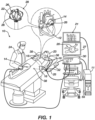
- System 10 includes multiple catheters, which are percutaneously inserted by operator 24 through the patient's 23 vascular system into a chamber or vascular structure of a heart 12.
- a delivery sheath catheter is inserted into the left or right atrium near a desired location in heart 12.
- a plurality of catheters can be inserted into the delivery sheath catheter so as to arrive at the desired location.
- the plurality of catheters may include catheters dedicated for sensing Intracardiac Electrogram (IEGM) signals, catheters dedicated for ablating and/or catheters dedicated for both sensing and ablating.
- An example catheter 14 that is configured for sensing IEGM is illustrated herein.
- Operator 24 brings a basket catheter 28 into contact with the heart wall for sensing a target site in heart 12. For ablation, operator 24 would similarly bring a distal end of an ablation catheter to a target site for ablating.
- IEGM Intracardiac Electrogram
- Catheter 14 is an exemplary catheter that includes one and preferably multiple electrodes 26 optionally distributed over a plurality of spines 22 forming a basket assembly 28 at a distal end and configured to sense the IEGM signals.
- Catheter 14 may additionally include a position sensor 29 embedded in or near the distal tip for tracking position and orientation of basket assembly 28.
- position sensor 29 is a magnetic based position sensor including three magnetic coils for sensing three-dimensional (3D) position and orientation.
- Magnetic based position sensor 29 may be operated together with a location pad 25 including a plurality of magnetic coils 32 configured to generate magnetic fields in a predefined working volume. Real time position of basket assembly 28 of catheter 14 may be tracked based on magnetic fields generated with location pad 25 and sensed by magnetic based position sensor 29. Details of the magnetic based position sensing technology are described in U.S. Patent Nos.
- System 10 includes one or more electrode patches 38 positioned for skin contact on patient 23 to establish location reference for location pad 25 as well as impedance-based tracking of electrodes 26.
- impedance-based tracking electrical current is directed toward electrodes 26 and sensed at electrode skin patches 38 so that the location of each electrode can be triangulated via the electrode patches 38. Details of the impedance-based location tracking technology are described in US Patent Nos. 7,536,218 ; 7,756,576 ; 7,848,787 ; 7,869,865 ; and 8,456,182 , each of which are incorporated herein by reference and attached in the Appendix included in priority application no. 63/386,798 .
- a recorder 11 displays electrograms 21 captured with body surface ECG electrodes 18 and intracardiac electrograms (IEGM) captured with electrodes 26 of catheter 14.
- Recorder 11 may include pacing capability for pacing the heart rhythm and/or may be electrically connected to a standalone pacer.
- System 10 may include an ablation energy generator 50 that is adapted to conduct ablative energy to one or more of electrodes at a distal tip of a catheter configured for ablating.
- Energy produced by ablation energy generator 50 may include, but is not limited to, radiofrequency (RF) energy or pulsed-field ablation (PFA) energy, including monopolar or bipolar high-voltage DC pulses as may be used to effect irreversible electroporation (IRE), or combinations thereof.
- RF radiofrequency
- PFA pulsed-field ablation
- the signals may be biphasic or monophasic.
- Patient interface unit (PIU) 30 is an interface configured to establish electrical communication between catheters, electrophysiological equipment, power supply and a workstation 55 for controlling operation of system 10.
- Electrophysiological equipment of system 10 may include for example, multiple catheters, location pad 25, body surface ECG electrodes 18, electrode patches 38, ablation energy generator 50, and recorder 11.
- PIU 30 additionally includes processing capability for implementing real-time computations of location of the catheters and for performing ECG calculations.
- Workstation 55 includes memory, processor unit with memory or storage with appropriate operating software loaded therein, and user interface capability. Workstation 55 may provide multiple functions, optionally including (1) modeling the endocardial anatomy in three-dimensions (3D) and rendering the model or anatomical map 20 for display on a display device 27, (2) displaying on display device 27 activation sequences (or other data) compiled from recorded electrograms 21 in representative visual indicia or imagery superimposed on the rendered anatomical map 20, (3) displaying real-time location and orientation of multiple catheters within the heart chamber, and (5) displaying on display device 27 sites of interest such as places where ablation energy has been applied.
- One commercial product embodying elements of the system 10 is available as the CARTO TM 3 System, available from Biosense Webster, Inc., 31A Technology Drive, Irvine, CA 92618.
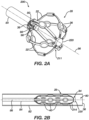
- FIG. 2A is a schematic pictorial illustration showing a perspective view of a medical probe 200 having a basket assembly 28 in an expanded form when unconstrained, such as by being advanced out of a tubular shaft lumen 80 at a distal end 36 of a tubular shaft 82.
- FIG. 2B shows the basket assembly in a collapsed form within tubular shaft 82.
- the spines 22 bow radially outwardly along a longitudinal axis 86 and in the collapsed form ( FIG. 2B ) the spines are constrained generally along the longitudinal axis 86 of tubular shaft 82.
- basket assembly 28 includes a plurality of flexible spines 22 that are formed at the end of a tubular shaft 84 and are connected at both ends.
- operator 24 can deploy basket assembly 28 by extending tubular shaft 84 from tubular shaft 82 causing the basket assembly 28 to exit the tubular shaft 84 and transition to the expanded form.
- Spines 22 may have elliptical (e.g., circular) or rectangular (that may appear to be flat) cross-sections, and include a flexible, resilient material (e.g., a shape-memory alloy such as nickel-titanium, also known as Nitinol) forming a strut as will be described in greater detail herein.
- a shape-memory alloy such as nickel-titanium, also known as Nitinol
- electrodes 40 can be configured to deliver ablation energy (RF and/or IRE) to tissue in heart 12.
- the electrodes can also be used to measure a physiological property such as local surface electrical potentials at respective locations on tissue in heart 12.
- the electrodes 40 can be biased such that a greater portion of the electrode 40 faces outwardly from the basket assembly 39 such that the electrodes 40 deliver a greater amount of electrical energy outwardly away from the basket assembly 28 (i.e., toward the heart 12 tissue) than inwardly toward the basket catheter 38.
- Examples of materials ideally suited for forming electrodes 40 include gold, platinum, and palladium (and their respective alloys). These materials also have high thermal conductivity which allows the minimal heat generated on the tissue (i.e., by the ablation energy delivered to the tissue) to be conducted through the electrodes to the back side of the electrodes (i.e., the portions of the electrodes on the inner sides of the spines), and then to the blood pool in heart 12.
- Basket assembly 28 can include a stem 96 that extends longitudinally from a distal end 36 of shaft 84 towards distal end 94 of basket assembly 28.
- the disclosed technology can include an irrigation system that delivers irrigation fluid to spray ports 98.
- stem 96 can include multiple spray ports 98, wherein each given spray port 98 can be angled to aim delivery of the irrigation fluid to either a given electrode 40 or to tissue in heart 12.
- the electrodes 40 can be cooled by aiming the irrigation fluid, via spray ports 98, at the portion of the electrodes 40 on the inner side of the spines 22.
- the basket assembly 28 can include a central intersection 211 at a point where the spines 22 converge near the distal end 94.
- the basket assembly 28 can include contact force sensor assembly 220 attached to the central intersections 211. By attaching the contact force sensor assembly 220 to the central intersection 211, the contact force sensor assembly 220 can be configured to detect a force applied to the basket assembly 28 at the distal end 94. In this way, the contact force sensor assembly 220 can be configured to more easily detect a force applied to the basket assembly 28 (e.g., when the basket assembly 28 contacts tissue).
- the contact force sensor assembly 220 can be or include any suitable type of contact force sensor for the application.
- the contact force sensor assembly 220 can be a load cell, a strain gauge, a piezoelectric sensor, a force sensing resistor, a magnetic force sensor, etc.
- the contact force sensor assembly 220 can include a proximal end 221 and a distal end 223.
- the proximal end 221 can house a magnetic field generator coil 222 and the distal end 223 can house a magnetic field sensor 224, or vice versa.
- the magnetic field generator coil 222 can be configured to generate a magnetic field while the magnetic field sensor 224 can be configured to detect the presence and magnitude of the magnetic field.
- the contact force sensor assembly 220 can further include a deflection portion 226 disposed between the proximal end 221 and the distal end 223.
- the deflection portion 226 can be configured to deflect when a force is applied to the contact force sensor assembly 220.
- the deflection portion 226 can be configured to permit the proximal end 221 and the distal end 223 of the contact force sensor assembly 220 to move closer to each other when a force is applied to the contact force sensor assembly 220.
- FIG. 3 shows a change in position "X" when the deflection portion 226 is compressed as a force is applied to the contact force sensor 220.
- the change in position "X" increases (or be a greater distance) when the deflection portion 226 is compressed to a greater extent.
- the deflection portion 226 is a spring positioned between the proximal end 221 and the distal end 223.
- the deflection portion 226 can comprise a helical spring formed into a body of the contact force sensor assembly 220.
- helical cuts can be made in the body of the contact force sensor assembly 220 to form a helical spring. In this way, the body of the contact force sensor assembly 220 can itself form a spring without the need for additional components.
- forces e.g., sub-gram forces
- the force sensor 430 can be a strain gauge, or other electrical resistance-based sensor, attached directly to the basket catheter 28. In this way, the disclosed technology can be better configured to detect a force applied to the basket catheter 28.
- FIGs. 4A and 4B are schematic pictorial illustrations showing perspective views of a basket catheter 428 with a force sensor 430 attached thereto, in accordance with an embodiment of the present invention.
- the force sensor 430 can be attached to a spine 22 of the basket catheter 428.
- the force sensor 430 can be attached to an inwardly-facing surface (as shown in FIG.
- the force sensor 430 can detect compressive or tensile forces depending on how a force is applied to the basket catheter 428. For example, as the central intersection 211 is pushed toward the proximal end of the basket catheter 428, the spines 22 flex and an outwardly-facing surface of the spine 22 experiences tensile forces while the inwardly-facing surface of the spine 22 experiences compressive forces.
- the workstation 55 can be programmed and calibrated to accurately analyze the change in signals received from the force sensor 430 depending on which surface of the spine 22 the force sensor 430 is placed.
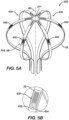
- a basket catheter 528 can include a plurality of force sensors 430 attached to the spines 22.
- FIG. 5A illustrates a perspective view
- FIG. 5B illustrates a detail view of the basket catheter 528 with a plurality of force sensors 430 attached thereto.
- FIGs. 5A and 5B illustrate the basket catheter 528 having the force sensors 430 attached to an outwardly-facing surface of the spine 22, one of skill in the art will appreciate that the contact force sensors 430 can alternatively or additionally be attached to an inwardly-facing surface.
- the disclosed technology can be configured to more accurately detect a force applied to the basket catheter 528 than basket catheters 28 having only a single force sensor.
- the workstation 55 can be configured to know which force sensor 430 is attached to which spine 22 (i.e., the workstation 55 can be programmed to correlate a signal received from a given force sensor 430 to an assigned spine 22 of the basket catheter 528). In this way, the workstation 55 can receive force signals from each of the force sensors 430 and determine the force at each spine 22 based on signals received from the assigned force sensor 430 attached to a given spine 22.
- the workstation 55 can be configured to detect a force applied to each spine 22 individually, determine how much force is applied to each spine 22, and determine a direction of the force applied to the basket catheter 528. For example, as a force is applied to a first side of the basket catheter 528, the degree to which each force sensor 430 is either compressed or strained can indicate where the force is originating from. To illustrate, the spine 22 nearest the location where the force is applied is more likely to compress on an outwardly-facing surface while the outwardly-facing surface of a spine 22 located further away from the location of the force is more likely to stretch as the force is applied.
- the disclosed technology can be configured to detect the magnitude and direction of a force applied to the basket catheter 528.
- the disclosed technology can further determine a difference in the force applied to a first side of the basket catheter 28 and a second side of the basket catheter 28.
- the disclosed technology can be configured to determine a deflection of the basket catheter 528. As will be appreciated, knowing the deflection of the basket catheter 528 can helpful to determine whether the electrodes 26 have made sufficient contact with tissue.
- For contact force sensors 430 can be sized and position as would be suitable for the particular application.
- the plurality of force sensors 430 are shown as having a given length and positioned on the spine 22 at the given illustrated positions, one of skill in the art will appreciate that he force sensors 430 can be larger or smaller than those shown in the figures.
- FIGs. 5A and 5B illustrate only a single force sensor 430 attached to a single spine 22, the disclosed technology can include multiple force sensors 430 attached to a given spine 22.
- the force sensors 430 can be attached to the spine 22 using any suitable method.
- the force sensors 430 can be attached to the spine 22 using adhesive, fasteners, crimps, etc.
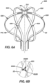
- FIGs. 6A and 6B are schematic pictorial illustrations showing perspective and detail views of a basket catheter 628 with a plurality of force sensor arrays 630 attached thereto. All of the features just described in relation to the basket catheter 528 can be incorporated into the basket catheter 628. However, rather than having a single force sensor 430 attached to the spine 22 as shown and described with the basket catheter 528, the basket catheter 628 can have a plurality of sensor arrays 630 attached to the spines 22.
- the sensor arrays 630 can comprise a plurality of force sensors 632A, 632B, and 632C arranged in different directions. For example, the sensor arrays 630 can comprise three sensors arranged at 120° in relation to each other.
- the sensor array 630 can be used to detect a direction of force applied to the spine 22.
- strain gauges are typically well suited for detecting compressive or tensile forces in a given direction but generally unable to accurately detect a force in a direction transverse to the given direction.
- the sensor array 630 can be configured to better detect a direction of a force applied to the spine 22.
- the workstation 55 can be configured to receive force data from each force sensor 632A, 632B, and 632C and, based on the received data, determine a magnitude and direction of the force applied to the spine 22. Furthermore, the workstation 55 can compile all of the force data received from each for sensor 632A, 632B, and 632C from each spine 22 and determine the magnitude and direction of the force applied to the basket catheter 628. Furthermore based on the magnitude and direction of the force applied to the basket catheter 628, the disclosed technology can be configured to determine a deflection of the basket catheter 628.
- FIGs. 7A and 7B are schematic pictorial illustrations showing perspective and detail views of another basket catheter 728 with a plurality of force sensors 730 integrated into the spines 22, in accordance with an embodiment of the present invention. All of the features described in relation to the basket catheter 528 can be incorporated into the basket catheter 728. However, as shown in FIGs. 7A and 7B , the basket catheter 728 can include force sensors 730 formed into the spines 22 of the basket catheter 728.
- the spines 22 can be made from nitinol, cobalt chromium, stainless steel, titanium, or some other biocompatible conductive material.
- the spine 22 can be formed to include a conductive section that has a variable electrical resistive properties as it is deformed, similar to a strain gauge.
- the workstation 55 can be configured to detect a change in the electrical resistance through the spine 22 due to the force sensor 730 being built directly into the spine 22. Furthermore, the workstation 55 can be configured to detect the magnitude and direction of the force applied to the basket catheter 728 as previously describe in the other examples given herein.
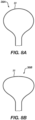
- FIGs. 8A and 8B are schematic pictorial illustrations showing a side view of a spine 22 of a given basket catheter 28, in accordance with examples of the disclosed technology.
- the spine 22 illustrated in FIGS. 8A and 8B is a single spine 22 and can be representative of the plurality of spines 22 of the basket assembly 28 described herein.
- the plurality of spines 22 forming the basket assembly 28 can each be configured to form the same or similar shape when in the expanded form such that the plurality of spines 22 together form a desired shape.
- the spine 22 as shown in FIG. 8A can be configured to form an approximately circular shape when in the expanded form.
- the plurality of spines 22 when combined with other spines 22 to form the basket assembly 28, can be configured to form an approximately spherical shape when the basket assembly 28 is in the expanded form.
- the spine 22 shown in FIG. 8B can be configured to form an approximately elliptical shape when in the expanded form.
- the plurality of spines 22 when combined with other spines 22 to form the basket assembly 28, can be configured to form an approximately oblate-spheroid shape when the basket assembly 28 is in the expanded form.
- the spines 22 can be further configured to form other various shapes as would be suitable for the particular application.
- the basket assembly 28 can be configured to position the various electrodes 40 attached to the spines 22 at various locations, with each location being nearer or farther from the distal end of the flexible tubular shaft 82.
- an electrode 40 attached to the spine 22 illustrated in FIG. 8A near the middle of the spine 22 would be farther from the distal end of the flexible tubular shaft 82 than the spine 22 illustrated in FIG. 8B when the basket assembly 28 is in the expanded form.
- the workstation 55 can be calibrated to detect the magnitude and direction of the force applied to the basket catheter 28 depending on which shape the basket 28 is configured to take when fully expanded. For example, as will be appreciated, as basket catheter 28 having a more spherical shape will exhibit slightly different characteristics as it deflects when a force is applied than a basket catheter 28 having a more oblate-spheroid shape. Thus, by calibrating the workstation 55 to analyze the data received from the force sensors 430, 630, 730 dependent on the shape of the basket catheter 28, the workstation 55 can more accurately determine the magnitude and direction of the force applied to the basket catheter 28.
- the disclosed technology can further include an electrically resistive jacket disposed over the spines 22 to electrically isolate the spines 22 from the electrodes 26. In this way, the electrodes 26 can be prevented from forming a short circuit to the spine 22.
- FIG. 9 is a flowchart illustrating a method 900 of operating a medical probe, in accordance with an embodiment of the present invention.
- the method 900 can include aligning receiving 902 force data from one or more force sensors (e.g., force sensors 430, 630, 730) attached to a spine (e.g., spine 22) of a basket catheter (e.g., basket catheter 28, 428, 528, 628, 728).
- the method 900 can include determining 904 a force applied to the basket catheter.
- the method 900 can include determining a magnitude and a direction of a force applied to the basket catheter.
- the method 900 can further include determining 906 a difference in force applied to a first side of the basket catheter compared to a second side of the basket catheter.
- the method can include determining 908 a deflection of the basket catheter and outputting 910 the calculated force, the calculated difference in force, and/or the calculated deflection.
- Outputting the calculated force, the calculated difference in force, and/or the calculated deflection can include outputting the foregoing to a connected display and/or to a processor for further processing.
- Further processing for example, can include correlating the calculated force, the calculated difference in force, and/or the calculated deflection to an image of a basket catheter to illustrate a deflection of the basket catheter.
- the method 900 can include any of the various features of the disclosed technology described herein and can be varied depending on the particular configuration. That is, the method 900 can be varied to include any of the features described in relation to basket catheter 28, basket catheter 428, basket catheter 528, basket catheter 628, and/or basket catheter 728.
Landscapes
- Health & Medical Sciences (AREA)
- Life Sciences & Earth Sciences (AREA)
- Engineering & Computer Science (AREA)
- Surgery (AREA)
- Public Health (AREA)
- Veterinary Medicine (AREA)
- Biomedical Technology (AREA)
- Heart & Thoracic Surgery (AREA)
- Medical Informatics (AREA)
- Molecular Biology (AREA)
- Animal Behavior & Ethology (AREA)
- General Health & Medical Sciences (AREA)
- Physics & Mathematics (AREA)
- Biophysics (AREA)
- Pathology (AREA)
- Nuclear Medicine, Radiotherapy & Molecular Imaging (AREA)
- Cardiology (AREA)
- Plasma & Fusion (AREA)
- Otolaryngology (AREA)
- Robotics (AREA)
- Physiology (AREA)
- Human Computer Interaction (AREA)
- Measurement And Recording Of Electrical Phenomena And Electrical Characteristics Of The Living Body (AREA)
- Media Introduction/Drainage Providing Device (AREA)
- Surgical Instruments (AREA)
Applications Claiming Priority (2)
| Application Number | Priority Date | Filing Date | Title |
|---|---|---|---|
| US202263386798P | 2022-12-09 | 2022-12-09 | |
| US18/500,617 US20240189023A1 (en) | 2022-12-09 | 2023-11-02 | Force sensors for basket catheters |
Publications (1)
| Publication Number | Publication Date |
|---|---|
| EP4382061A1 true EP4382061A1 (de) | 2024-06-12 |
Family
ID=89164582
Family Applications (1)
| Application Number | Title | Priority Date | Filing Date |
|---|---|---|---|
| EP23215306.4A Pending EP4382061A1 (de) | 2022-12-09 | 2023-12-08 | Kraftsensoren für korbkatheter |
Country Status (4)
| Country | Link |
|---|---|
| US (1) | US20240189023A1 (de) |
| EP (1) | EP4382061A1 (de) |
| JP (1) | JP2024083301A (de) |
| IL (1) | IL308966A (de) |
Citations (27)
| Publication number | Priority date | Publication date | Assignee | Title |
|---|---|---|---|---|
| US5391199A (en) | 1993-07-20 | 1995-02-21 | Biosense, Inc. | Apparatus and method for treating cardiac arrhythmias |
| WO1995008943A2 (en) * | 1993-09-23 | 1995-04-06 | Cardiac Pathways Corporation | Apparatus and method for detecting contact pressure |
| US5558091A (en) | 1993-10-06 | 1996-09-24 | Biosense, Inc. | Magnetic determination of position and orientation |
| US6172499B1 (en) | 1999-10-29 | 2001-01-09 | Ascension Technology Corporation | Eddy current error-reduced AC magnetic position measurement system |
| US6239724B1 (en) | 1997-12-30 | 2001-05-29 | Remon Medical Technologies, Ltd. | System and method for telemetrically providing intrabody spatial position |
| US6332089B1 (en) | 1996-02-15 | 2001-12-18 | Biosense, Inc. | Medical procedures and apparatus using intrabody probes |
| US6484118B1 (en) | 2000-07-20 | 2002-11-19 | Biosense, Inc. | Electromagnetic position single axis system |
| US6618612B1 (en) | 1996-02-15 | 2003-09-09 | Biosense, Inc. | Independently positionable transducers for location system |
| US6690963B2 (en) | 1995-01-24 | 2004-02-10 | Biosense, Inc. | System for determining the location and orientation of an invasive medical instrument |
| US6892091B1 (en) | 2000-02-18 | 2005-05-10 | Biosense, Inc. | Catheter, method and apparatus for generating an electrical map of a chamber of the heart |
| US7536218B2 (en) | 2005-07-15 | 2009-05-19 | Biosense Webster, Inc. | Hybrid magnetic-based and impedance-based position sensing |
| US7756576B2 (en) | 2005-08-26 | 2010-07-13 | Biosense Webster, Inc. | Position sensing and detection of skin impedance |
| US7848787B2 (en) | 2005-07-08 | 2010-12-07 | Biosense Webster, Inc. | Relative impedance measurement |
| US7869865B2 (en) | 2005-01-07 | 2011-01-11 | Biosense Webster, Inc. | Current-based position sensing |
| US8456182B2 (en) | 2008-09-30 | 2013-06-04 | Biosense Webster, Inc. | Current localization tracker |
| US9272132B2 (en) * | 2012-11-02 | 2016-03-01 | Boston Scientific Scimed, Inc. | Medical device for treating airways and related methods of use |
| WO2017041889A2 (en) * | 2015-09-07 | 2017-03-16 | Ablacon Inc. | Elongated medical device suitable for intravascular insertion and method of making an elongated medical device suitable for intravascular insertion |
| US20180360534A1 (en) * | 2017-06-19 | 2018-12-20 | St. Jude Medical, Cardiology Division, Inc. | Apparatuses and methods for high-density sensing and ablation during a medical procedure |
| EP2641555B1 (de) * | 2012-03-20 | 2019-06-19 | Biosense Webster (Israel) Ltd. | Katheter mit mehreren bewässerten Elektroden und einem Kraftsensor |
| US20210161592A1 (en) | 2019-12-03 | 2021-06-03 | Biosense Webster (Israel) Ltd. | Pulse Generator for Irreversible Electroporation |
| US20210169550A1 (en) | 2019-12-05 | 2021-06-10 | Biosense Webster (Israel) Ltd. | Generating and interleaving of irreversible-electroporation and radiofrequnecy ablation (ire/rfa) waveforms |
| US20210169567A1 (en) | 2019-12-09 | 2021-06-10 | Biosense Webster (Israel) Ltd. | Irreversible-electroporation (ire) balloon catheter with membrane-insulated high-voltage balloon wires |
| US20210169568A1 (en) | 2019-12-09 | 2021-06-10 | Biosense Webster (Israel) Ltd. | Oriented irreversible-electroporation (ire) pulses to compensate for cell size and orientation |
| US20210177503A1 (en) | 2019-12-11 | 2021-06-17 | Biosense Webster (Israel) Ltd. | Regulating delivery of irreversible electroporation pulses according to transferred energy |
| US20210186604A1 (en) | 2019-12-24 | 2021-06-24 | Biosense Webster (Israel) Ltd. | Irreversible electroporation (ire) based on field, contact force and time |
| US20210196372A1 (en) | 2019-12-31 | 2021-07-01 | Biosense Webster (Israel) Ltd. | Using irrigation on irreversible-electroporation (ire) electrodes to prevent arcing |
| US11234762B2 (en) * | 2015-12-15 | 2022-02-01 | Agency For Science, Technology And Research | Method and deployable multi-spine apparatus for catheter-based renal denervation |
-
2023
- 2023-11-02 US US18/500,617 patent/US20240189023A1/en active Pending
- 2023-11-29 IL IL308966A patent/IL308966A/en unknown
- 2023-12-08 EP EP23215306.4A patent/EP4382061A1/de active Pending
- 2023-12-08 JP JP2023207582A patent/JP2024083301A/ja active Pending
Patent Citations (29)
| Publication number | Priority date | Publication date | Assignee | Title |
|---|---|---|---|---|
| US5391199A (en) | 1993-07-20 | 1995-02-21 | Biosense, Inc. | Apparatus and method for treating cardiac arrhythmias |
| US5443489A (en) | 1993-07-20 | 1995-08-22 | Biosense, Inc. | Apparatus and method for ablation |
| WO1995008943A2 (en) * | 1993-09-23 | 1995-04-06 | Cardiac Pathways Corporation | Apparatus and method for detecting contact pressure |
| US5558091A (en) | 1993-10-06 | 1996-09-24 | Biosense, Inc. | Magnetic determination of position and orientation |
| US6690963B2 (en) | 1995-01-24 | 2004-02-10 | Biosense, Inc. | System for determining the location and orientation of an invasive medical instrument |
| US6332089B1 (en) | 1996-02-15 | 2001-12-18 | Biosense, Inc. | Medical procedures and apparatus using intrabody probes |
| US6618612B1 (en) | 1996-02-15 | 2003-09-09 | Biosense, Inc. | Independently positionable transducers for location system |
| US6788967B2 (en) | 1997-05-14 | 2004-09-07 | Biosense, Inc. | Medical diagnosis, treatment and imaging systems |
| US6239724B1 (en) | 1997-12-30 | 2001-05-29 | Remon Medical Technologies, Ltd. | System and method for telemetrically providing intrabody spatial position |
| US6172499B1 (en) | 1999-10-29 | 2001-01-09 | Ascension Technology Corporation | Eddy current error-reduced AC magnetic position measurement system |
| US6892091B1 (en) | 2000-02-18 | 2005-05-10 | Biosense, Inc. | Catheter, method and apparatus for generating an electrical map of a chamber of the heart |
| US6484118B1 (en) | 2000-07-20 | 2002-11-19 | Biosense, Inc. | Electromagnetic position single axis system |
| US7869865B2 (en) | 2005-01-07 | 2011-01-11 | Biosense Webster, Inc. | Current-based position sensing |
| US7848787B2 (en) | 2005-07-08 | 2010-12-07 | Biosense Webster, Inc. | Relative impedance measurement |
| US7536218B2 (en) | 2005-07-15 | 2009-05-19 | Biosense Webster, Inc. | Hybrid magnetic-based and impedance-based position sensing |
| US7756576B2 (en) | 2005-08-26 | 2010-07-13 | Biosense Webster, Inc. | Position sensing and detection of skin impedance |
| US8456182B2 (en) | 2008-09-30 | 2013-06-04 | Biosense Webster, Inc. | Current localization tracker |
| EP2641555B1 (de) * | 2012-03-20 | 2019-06-19 | Biosense Webster (Israel) Ltd. | Katheter mit mehreren bewässerten Elektroden und einem Kraftsensor |
| US9272132B2 (en) * | 2012-11-02 | 2016-03-01 | Boston Scientific Scimed, Inc. | Medical device for treating airways and related methods of use |
| WO2017041889A2 (en) * | 2015-09-07 | 2017-03-16 | Ablacon Inc. | Elongated medical device suitable for intravascular insertion and method of making an elongated medical device suitable for intravascular insertion |
| US11234762B2 (en) * | 2015-12-15 | 2022-02-01 | Agency For Science, Technology And Research | Method and deployable multi-spine apparatus for catheter-based renal denervation |
| US20180360534A1 (en) * | 2017-06-19 | 2018-12-20 | St. Jude Medical, Cardiology Division, Inc. | Apparatuses and methods for high-density sensing and ablation during a medical procedure |
| US20210161592A1 (en) | 2019-12-03 | 2021-06-03 | Biosense Webster (Israel) Ltd. | Pulse Generator for Irreversible Electroporation |
| US20210169550A1 (en) | 2019-12-05 | 2021-06-10 | Biosense Webster (Israel) Ltd. | Generating and interleaving of irreversible-electroporation and radiofrequnecy ablation (ire/rfa) waveforms |
| US20210169567A1 (en) | 2019-12-09 | 2021-06-10 | Biosense Webster (Israel) Ltd. | Irreversible-electroporation (ire) balloon catheter with membrane-insulated high-voltage balloon wires |
| US20210169568A1 (en) | 2019-12-09 | 2021-06-10 | Biosense Webster (Israel) Ltd. | Oriented irreversible-electroporation (ire) pulses to compensate for cell size and orientation |
| US20210177503A1 (en) | 2019-12-11 | 2021-06-17 | Biosense Webster (Israel) Ltd. | Regulating delivery of irreversible electroporation pulses according to transferred energy |
| US20210186604A1 (en) | 2019-12-24 | 2021-06-24 | Biosense Webster (Israel) Ltd. | Irreversible electroporation (ire) based on field, contact force and time |
| US20210196372A1 (en) | 2019-12-31 | 2021-07-01 | Biosense Webster (Israel) Ltd. | Using irrigation on irreversible-electroporation (ire) electrodes to prevent arcing |
Also Published As
| Publication number | Publication date |
|---|---|
| US20240189023A1 (en) | 2024-06-13 |
| JP2024083301A (ja) | 2024-06-20 |
| IL308966A (en) | 2024-07-01 |
Similar Documents
| Publication | Publication Date | Title |
|---|---|---|
| US20230346462A1 (en) | Strengthened expandable baskets for medical probes and medical probes containing strengthen expandable baskets | |
| EP4382061A1 (de) | Kraftsensoren für korbkatheter | |
| EP4393428A1 (de) | Kontaktkraftsensoren für korbkatheter und verfahren zur verwendung davon | |
| EP4393438A2 (de) | Positions- und kraftsensoren für katheter | |
| EP4382060A1 (de) | Elektroden für korbkatheter | |
| CN118161255A (zh) | 用于篮式导管的力传感器 | |
| US20230346459A1 (en) | Basket catheter with force sensor having bayonet mount | |
| US20240216054A1 (en) | Systems and methods for cylindrical cage mapping and ablation catheters comprising flexible circuits | |
| US20230346455A1 (en) | Basket catheter with force sensor having bayonet mount | |
| EP4393425A1 (de) | Verformter wirbelsäulenelektrodenkorb und verfahren dafür | |
| EP4393427A1 (de) | Zylindrische käfigsysteme und verfahren für verteilten gewebekontakt zur kartierung und ablation | |
| EP4268748A2 (de) | Spülnabe für einen ablationskatheter | |
| US20240216053A1 (en) | Systems and methods for cylindrical cage mapping and ablation catheters having integrated electrodes | |
| US20240216052A1 (en) | Systems and methods for cylindrical cage mapping and ablation catheters having flexible circuits | |
| EP4393432A2 (de) | Ablationskatheter mit einem ausweitbaren gewebe mit elektrisch leitenden strängen | |
| US20240216055A1 (en) | Fractal cylindrical cage systems and methods for distributed tissue contact for mapping and ablation | |
| US20240197391A1 (en) | Basket assembly with atraumatic tip electrode and methods of making thereof | |
| CN118266862A (zh) | 用于篮式导管的接触力传感器及其使用方法 | |
| IL309727A (en) | Irrigation center for ablation catheter | |
| CN118266907A (zh) | 用于导管的位置传感器和力传感器 | |
| CN118141505A (zh) | 用于篮式导管的电极 |
Legal Events
| Date | Code | Title | Description |
|---|---|---|---|
| PUAI | Public reference made under article 153(3) epc to a published international application that has entered the european phase |
Free format text: ORIGINAL CODE: 0009012 |
|
| STAA | Information on the status of an ep patent application or granted ep patent |
Free format text: STATUS: THE APPLICATION HAS BEEN PUBLISHED |
|
| AK | Designated contracting states |
Kind code of ref document: A1 Designated state(s): AL AT BE BG CH CY CZ DE DK EE ES FI FR GB GR HR HU IE IS IT LI LT LU LV MC ME MK MT NL NO PL PT RO RS SE SI SK SM TR |