EP4381630B1 - Optische kommunikationsnetzwerkvorrichtung und verfahren zur bereitstellung eines optischen signals - Google Patents
Optische kommunikationsnetzwerkvorrichtung und verfahren zur bereitstellung eines optischen signals Download PDFInfo
- Publication number
- EP4381630B1 EP4381630B1 EP21749656.1A EP21749656A EP4381630B1 EP 4381630 B1 EP4381630 B1 EP 4381630B1 EP 21749656 A EP21749656 A EP 21749656A EP 4381630 B1 EP4381630 B1 EP 4381630B1
- Authority
- EP
- European Patent Office
- Prior art keywords
- optical
- external
- internal
- signal
- laser
- Prior art date
- Legal status (The legal status is an assumption and is not a legal conclusion. Google has not performed a legal analysis and makes no representation as to the accuracy of the status listed.)
- Active
Links
Images


Classifications
-
- H—ELECTRICITY
- H04—ELECTRIC COMMUNICATION TECHNIQUE
- H04B—TRANSMISSION
- H04B10/00—Transmission systems employing electromagnetic waves other than radio-waves, e.g. infrared, visible or ultraviolet light, or employing corpuscular radiation, e.g. quantum communication
- H04B10/50—Transmitters
- H04B10/564—Power control
-
- G—PHYSICS
- G02—OPTICS
- G02B—OPTICAL ELEMENTS, SYSTEMS OR APPARATUS
- G02B6/00—Light guides; Structural details of arrangements comprising light guides and other optical elements, e.g. couplings
- G02B6/24—Coupling light guides
- G02B6/42—Coupling light guides with opto-electronic elements
- G02B6/4201—Packages, e.g. shape, construction, internal or external details
- G02B6/4266—Thermal aspects, temperature control or temperature monitoring
-
- H—ELECTRICITY
- H01—ELECTRIC ELEMENTS
- H01S—DEVICES USING THE PROCESS OF LIGHT AMPLIFICATION BY STIMULATED EMISSION OF RADIATION [LASER] TO AMPLIFY OR GENERATE LIGHT; DEVICES USING STIMULATED EMISSION OF ELECTROMAGNETIC RADIATION IN WAVE RANGES OTHER THAN OPTICAL
- H01S3/00—Lasers, i.e. devices using stimulated emission of electromagnetic radiation in the infrared, visible or ultraviolet wave range
- H01S3/02—Constructional details
- H01S3/04—Arrangements for thermal management
-
- H—ELECTRICITY
- H04—ELECTRIC COMMUNICATION TECHNIQUE
- H04B—TRANSMISSION
- H04B10/00—Transmission systems employing electromagnetic waves other than radio-waves, e.g. infrared, visible or ultraviolet light, or employing corpuscular radiation, e.g. quantum communication
- H04B10/50—Transmitters
- H04B10/501—Structural aspects
- H04B10/503—Laser transmitters
- H04B10/505—Laser transmitters using external modulation
-
- H—ELECTRICITY
- H04—ELECTRIC COMMUNICATION TECHNIQUE
- H04J—MULTIPLEX COMMUNICATION
- H04J14/00—Optical multiplex systems
- H04J14/02—Wavelength-division multiplex systems
- H04J14/0287—Protection in WDM systems
- H04J14/0297—Optical equipment protection
Definitions
- the invention relates to a communications network optical apparatus and to a method of providing optical signals for an optical module in a communications network.
- Co-packaged optics has been proposed to reduce the cost of packaging and power consumption by shortening the electrical lines between the optical module and the ASIC. It is estimated that the cost of packaging accounts for the 80% of the total cost of a transceiver according to IPSR 2020. An additional cost reduction comes from the integration of multiple laser sources into a single optical transceiver with multiple channels. Nevertheless, the co-packaged solution presents some drawbacks in terms of serviceability and thermal management of the laser sources.
- An integrated laser source dissipates a small thermal load of approximately 100 mW, however, because the lasers are very small in size (typically few hundreds of microns), the device-level heat flux dissipated per laser is large, around 1 kW/cm2. Removing this level of heat flux locally through an acceptable thermal resistance is extremely challenging and this may reduce the level of integration that can be achieved.
- thermo-electric cooler also indicated as macro-TEC.
- the TEC acts to maintain a reference temperature of the photonic chip and avoids the decay of laser performances during operation.
- Semiconductor lasers performances depend strongly on temperature.
- the threshold current of semiconductor lasers increases fast with temperature and their yield generally decreases above 300 K. Additionally, laser lifetime decreases with exposure to high temperature according to the Arrhenius model.
- Standby/spare lasers have been proposed to address the issue of laser failure in integrated photonic chips e.g. in US 2018/0183513 A1 which describes the replacement of failed lasers with auxiliary lasers that are included on the photonic chip so that when a failure is detected on a working laser the standby/spare laser can take over.
- Document US 2014/376579 A1 discloses an example of an optical module using internal replacement lasers to mitigate laser induced temperature failure.
- An aspect of the invention provides communications network optical apparatus comprising an optical module and a controller.
- the optical module comprises optical modulators, internal lasers, an input port, optical routing devices and a temperature sensor.
- the optical modulators are arranged to modulate optical signals.
- the internal lasers arranged to generate internal optical signals to be modulated by the optical modulators.
- the input port is arranged to receive an external optical signal from an external laser.
- the optical routing devices are arranged to route internal optical signals from internal lasers to optical modulators and to route an external optical signal from the input port to at least one of the optical modulators.
- the temperature sensor is arranged to sense a temperature of the internal lasers and to generate a temperature reporting signal.
- the controller comprises processing circuitry and memory containing instructions executable by said processing circuitry whereby said controller is operative to perform operations.
- the operations include receiving the temperature reporting signal.
- the operations additionally include determining that a thermal protection condition exists based on the temperature of the internal lasers.
- the operations additionally include, in response to the determining, generating control signals configured to cause the external optical signal to be provided to at least one optical modulator and to cause an operating power of at least one respective internal laser to be reduced.
- the apparatus enables thermal stress relief for lasers integrated within optical modules where dissipation of heat is particularly difficult by switching from using the internal laser to using an external optical signal when a thermal stress condition occurs.
- the apparatus may be particularly advantageous for use in applications where internal lasers experience thermal stress for a limited time relative to their total time of operation.
- the apparatus may enable an optical module to switch to an external optical signal when the optical module's internal lasers are experiencing thermal stress that is limited in space and time, to mitigate the thermal stress experienced by an internal laser. Mitigating the thermal stress in this way may mitigate reduction in the operating lifetime of the internal laser and may mitigate a reduction in the performance of the internal laser.
- the apparatus may advantageously enable the optical module to operate most of the time with the cost-effective internal lasers and to use an external optical signal from an external laser occasionally, for example when a peak in traffic causes a large temperature increase in the optical module.
- control signals comprise a first control signal and a second control signal.
- the first control signal is for providing power control commands to an external laser.
- the second control signal is for providing power control commands to the at least one internal laser.
- the controller is caused to generate the first control signal to provide a power-on control command to the external laser in response to the determining that a thermal protection condition exists.
- the controller is additionally caused to subsequently generate the second control signal to provide at least one power control command configured to cause the operating power of the at least one respective internal laser to be reduced.
- the apparatus may advantageously enable the external laser to be switched on only when an external optical signal is required. Reducing the internal laser operating power after causing the external laser to switch on may advantageously enable the optical module to alternate the use of an internal laser and an external laser without causing bit errors or performance degradation in the optical module.
- the operating power of the at least one respective internal laser is reduced by switching off the operating power, by gradually reducing the operating power and then switching off the operating power, or by gradually reducing the operating power to zero.
- the apparatus is thus advantageously able to perform an instantaneous hand-over from the internal laser to the external optical signal or a gradual hand-over.
- the first control signal provides a power-on control command configured to cause the external laser to gradually increase a power of the external optical signal up to an operating power as the operating power of the internal laser is gradually reduced. This may avoid any fluctuation in the optical power received at the optical modulator.
- the optical module further comprises an optical tap configured to route a portion of an external optical signal received at the input port to the at least one respective internal laser for injection locking the at least one internal laser with the external optical signal.
- the second control signal is generated subsequently to the injection locking.
- the wavelength of the internal optical signal may be matched to the wavelength of the external optical signal, to within the wavelength tolerance of an optical channel, before the external optical signal takes over from the internal optical signal.
- Injection locking may also enable the phase of the internal optical signal to be aligned to the phase of the external optical signal before the external optical signal takes over from the internal optical signal. Use of injection locking may avoid optical interference occurring between the internal optical signal and the external optical signal when the internal and external optical signals are coexisting.
- the external optical signal has a first frequency and the internal optical signals have frequencies different to the first frequency by a frequency difference that is greater than a defined detection bandwidth. This may advantageously cause any optical beat signal generated between coexisting internal and external optical signals to be outside a defined detection bandwidth.
- the optical routing devices comprise a first optical waveguide, a second optical waveguide, a third optical waveguide and at least one directional phase-shifting coupler.
- the first optical waveguide is coupled to an optical modulator.
- the second optical waveguide is coupled to an internal laser.
- the third optical waveguide is coupled to the input port.
- the at least one directional phase-shifting coupler is for coupling the second optical waveguide to the first optical waveguide or the third optical waveguide to the first optical waveguide.
- the control signals further comprise a third control signal for providing control commands to the at least one directional phase-shifting coupler.
- the controller is caused to generate the third control signal, after generating the first control signal.
- the third control signal is configured to provide control commands.
- the control commands are to cause the at least one directional phase-shifting coupler to couple the internal optical signal into the first optical waveguide with a first phase.
- the control commands are additionally to cause the at least one directional phase-shifting coupler to stop coupling the internal optical signal into the first optical waveguide.
- the control commands are additionally to cause the at least one directional phase-shifting coupler to couple the external optical signal into the first optical waveguide with the first phase. This may avoid any fluctuation in the optical power received at the optical modulator. This may also avoid optical interference occurring between the internal optical signal and the external optical signal when the internal and external optical signals are coexisting.
- the third control signal is additionally configured to provide further control commands.
- the further control commands are to cause the at least one directional phase-shifting coupler to gradually reduce to nothing the coupling of the internal optical signal into the first optical waveguide.
- the further control commands are additionally to cause the at least one directional phase-shifting coupler to gradually increase the coupling of the external optical signal into the first optical waveguide with the first phase. This may avoid any fluctuation in the optical power received at the optical modulator.
- the optical routing devices comprise an all-optical switch and the optical module further comprises an optical tap.
- the all-optical switch has a first input connected to an internal laser, a second input connected to the input port and an output connected to an optical modulator.
- the optical tap is configured to route a portion of an external optical signal received at the input port of the optical module to the all-optical switch as a switching signal for the all-optical switch.
- the all-optical switch has a first switch condition in which the first input is connected to the output and a second switch condition in which the second input is connected to the output.
- the all-optical switch is arranged to switch from the first switch condition to the second switch condition responsive to receipt of a said switching signal.
- An all-optical switch may enable fast switching which may avoid any fluctuation in the optical power received at the optical modulator and may avoid transmission downtime.
- the all-optical switch has a switching time for switching between the first switching condition and the second switching condition.
- the switching time is less than 10ps.
- the all-optical switch may advantageously enable very fast switching, effectively between bits modulated onto the optical signal, which may avoid any fluctuation in the optical power received at the optical modulator, due to interference caused by the coexistence of internal and external optical signals at the same wavelength, and any loss of bits.
- the apparatus further comprises a second optical module and a variable power coupler.
- the variable power coupler is configured to receive the external optical signal from the external laser and is configured to power split the external optical signal to send a first portion of the external optical signal to the optical module and second portion of the external optical signal to the second optical module.
- a single external optical signal, provided by a single external laser, may thus be used to provide external optical signals to two optical modules, reducing the cost as compared to providing an external laser for each module.
- the controller is further operative to perform further operations.
- the further operations include receiving a further temperature reporting signal.
- the further operations additionally include determining that a thermal protection condition no longer exists based on the temperature of the internal lasers.
- the further operations additionally include, in response to said determining, generating control signals configured to stop the external optical signal being provided to the at least one optical modulator and to cause the reduction in the operating power of the at least one respective internal laser to be reversed.
- the apparatus may advantageously return to operation using the internal laser once a thermal stress condition has ended.
- the apparatus comprises a plurality of optical modules and an optical switch apparatus configured to receive external optical signals.
- the controller is operative to receive temperature reporting signals from the optical modules and to determine that a thermal protection condition exists at an optical module based on the temperature of its internal lasers.
- the control signals are further configured to cause the optical switch apparatus to route one of the external optical signals to the optical module having said thermal protection condition.
- the apparatus may reduce the number of external lasers that are necessary to provide external optical signals to protect the internal lasers of an optical module. Also, this may increase the reliability of the apparatus because in case of failure of an external laser source an external optical signal from another external laser source can be used.
- the apparatus further comprise at least one external laser arranged to generate at least one external optical signal.
- the apparatus further comprises a plurality of external lasers arranged to generate the external optical signals.
- the plurality of external lasers and the optical switch apparatus are located remote from the plurality of optical modules.
- the apparatus may advantageously enable the optical module to operate most of the time with the cost-effective internal lasers and to use external optical signals from a pool of shared external lasers occasionally, for example when a peak of traffic causes a large temperature increase in the optical module. Also, this may increase the reliability of the apparatus because in case of failure of an external laser another one of the external lasers can be used.
- an optical module is a co-packaged optics, CPO, module.
- the apparatus may advantageously enable combining the cost-saving of using a CPO optical module with serviceability and reliability with a solution where the external optical signal is used only in the cases where internal lasers are under thermal stress.
- an optical module is provided in a Radio Unit.
- An aspect of the invention provides a method of providing optical signals for an optical module in a communications network.
- the method comprises the following steps.
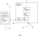
- an embodiment provides communications network optical apparatus 100 comprising an optical module 120 and a controller 140.
- the optical module 120 comprises optical modulators 122, internal lasers 124, an input port 126, optical routing devices 128 and a temperature sensor 130.
- the optical modulators are arranged to modulate optical signals.
- the internal lasers are arranged to generate internal optical signals to be modulated by the optical modulators.
- the temperature sensor is arranged to sense a temperature of the internal lasers and to generate a temperature reporting signal.
- the input port is arranged to receive an external optical signal 132 from an external laser.
- the optical routing devices are arranged to route internal optical signals from internal lasers to optical modulators and to route an external optical signal from the input port to at least one of the optical modulators.
- the controller comprises processing circuitry 142 and memory 144 containing instructions which when executed by the processing circuitry cause the controller to perform operations including:
- control signals comprise a first control signal 146 for providing power control commands to an external laser and a second control signal 148 for providing power control commands to the internal laser.
- the controller 140 is caused to generate the first control signal to provide a power-on control command to the external laser in response to determining that a thermal protection condition exists.
- the controller is also caused to subsequently generate the second control signal, after generating the first control signal, to provide at least one power control command configured to cause the operating power of the internal laser to be reduced.
- the handover of the light input from the internal laser to the external optical signal is performed in a way that the optical power input to the optical modulator is maintained.
- the operating power of the internal laser is reduced by switching off the operating power. In an alternative embodiment, the operating power of the internal laser is reduced by gradually reducing the operating power and then switching off the operating power. In an alternative embodiment, the operating power of the internal laser is reduced by gradually reducing the operating power to zero.
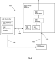
- the communications network optical apparatus 150 further comprises an external laser 152 arranged to generate the external optical signal 132.
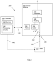
- An embodiment provides communications network optical apparatus 200 as illustrated in Figure 3 .
- the optical module additionally comprises an optical tap 202.
- the optical tap is configured to route a portion of an external optical signal 132 received at the input port 126 to the internal laser 124.
- the portion of the external optical signal is used to injection lock the internal laser with the external optical signal.
- the second control signal is generated subsequently to the injection locking, to provide at least one power control command configured to cause the operating power of the internal laser to be reduced after it has been injection locked with the external optical signal.
- Injection locking enables high spectral overlap to be achieved between the external optical signal and the internal optical signal.
- the internal laser 124 (the 'slave' laser) is tuned to the frequency of the external optical signal by injecting a small amount of the external optical signal into the resonant cavity of the internal laser.
- Phase alignment is relevant only in the case where the frequency of the external optical signal and the frequency of the internal optical signal are set to be the substantially the same (i.e. to have a high percentage of spectral overlap), means that interference may occur if the phases are not aligned.
- the external optical signal 132 has a first frequency and the internal optical signals have frequencies different to the first frequency.
- the frequencies of the internal optical signals are different to the first frequency by a frequency difference that is greater than a defined detection bandwidth.
- the internal optical signal and the external optical signal co-exist during handover, setting this frequency means that any beat signal is generated between the internal and external optical signals does not fall within a defined detection bandwidth, so it is not detected by a receiver.
- Controlling the frequencies may be easier to implement and more robust than phase control, however it may be less suitable for use in a dense wavelength division multiplexing, DWDM, system since it would necessarily increase the bandwidth required by each channel. It may be easily adopted in 'gray optics' systems used in interconnect/data centers or course WDM, CWDM, systems.
- the communications network optical apparatus 250 further comprises an external laser 152 arranged to generate the external optical signal 132.
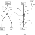
- FIGS 5 to 7 illustrate embodiments 400, 500, 600 of the optical routing device 128.
- Each embodiment supports gradual handover from the internal laser 124 to the external optical signal 132, and vice versa, to maintain the optical power output of the optical module 120.
- Each optical routing device couples the internal optical signal and the external optical signal into a common waveguide 406, 504, 602 that in turn feeds an optical modulator 122 in the optical module.
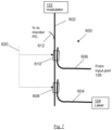
- the optical routing device 400 is a passive power coupler, such as a Y-branch coupler.
- a first input branch 402 is coupled to the internal laser 124
- a second input branch 404 is coupled to the input port 126, to receive the external optical signal 132
- a common output branch 406 is coupled to the optical modulator 122.
- An optical tap 408 is also provided to deliver a small percentage of the output light to a monitor photodiode, PD, not shown.
- the monitor photodiode will detect an increase in output optical power when the external optical signal is present and output a photodiode signal to the controller 140.
- the controller 140 is operable, in response to receiving a photodiode signal indicating an increase in output optical power, to generate the second control signal 148 to provide at least one power control command configured to cause the bias current of the internal laser to be reduced to zero.
- the photodiode signal may be used to cause the controller 140 to generate a first control signal 146 comprising power control commands to drive the gradual shut down of the external laser providing the external optical signal.
- the optical routing device 500 comprises a first optical waveguide 502, a second optical waveguide 504, a third optical waveguide 506 and a directional phase-shifting coupler 508.
- the first optical waveguide is coupled to the optical modulator 122, the second optical waveguide is coupled to the internal laser 124 and the third optical waveguide is coupled to the input port 126.
- the directional phase-shifting coupler 508 is configured to couple the second optical waveguide to the first optical waveguide or to couple the third optical waveguide to the first optical waveguide.
- the directional phase-shifting coupler also includes a phase shifter configured to match the phase of the external optical signal to the phase of the internal optical signal.
- the controller 140 is additionally caused to generate a third control signal, after generating the first control signal.
- the third control signal is for providing control commands to the directional phase-shifting coupler.
- the internal laser 124 generates the internal optical signal at a first wavelength (optical frequency) and a first phase.
- the external optical signal 132 is at the first wavelength and a second phase, which will in general be different to the first phase.
- the third control signal is configured to provide control commands to:
- the optical routing device 500 can be used to avoid destructive interference between the internal and external optical signals during handover from the internal optical signal to the external optical signal, and back.
- the optical routing device 500 comprises a passive directional coupler, configured to transfer 100% of the external optical signal into the first waveguide 502.
- control commands cause the directional phase-shifting coupler 508 to gradually reduce to nothing the coupling of the internal optical signal into the first optical waveguide and gradually increase the coupling of the external optical signal into the first optical waveguide with the first phase. This may enable a consistent optical power to be output from the optical routing device to the optical modulator.
- the optical routing device 600 comprises a first optical waveguide 602, a second optical waveguide 604, a third optical waveguide 606, a first directional phase-shifting coupler 608 and a second directional phase-shifting coupler 610.
- the first optical waveguide is coupled to the optical modulator 122, the second optical waveguide is coupled to the internal laser 124 and the third optical waveguide is coupled to the input port 126.
- the first directional phase-shifting coupler 608 is configured to couple the second optical waveguide to the first optical waveguide, to couple the internal optical signal into the first optical waveguide.
- the second directional phase-shifting coupler 610 is configured to couple the third optical waveguide to the first optical waveguide, to couple the external optical signal into the first optical waveguide.
- the directional phase-shifting couplers also include phase shifters configured to match the phase of the external optical signal to the phase of the internal optical signal.
- the controller 140 is additionally caused to generate a third control signal, after generating the first control signal.
- the third control signal is for providing control commands to the directional phase-shifting couplers.
- the internal laser 124 generates the internal optical signal at a first wavelength (optical frequency) and a first phase.
- the external optical signal 132 is at the first wavelength and a second phase, which will in general be different to the first phase.
- the third control signal is configured to provide control commands to:
- control commands cause the first directional phase-shifting coupler 608 to gradually reduce to nothing the coupling of the internal optical signal into the first optical waveguide and cause the second directional phase-shifting coupler 610 to gradually increase the coupling of the external optical signal into the first optical waveguide with the first phase.
- a consistent optical power may be output from the optical routing device to the optical modulator.
- the third control signal is configured to provide control commands to cause the first directional phase-shifting coupler 608 to apply a phase-shift to the internal optical signal so that has a third phase, different to the first and second phases.
- the control commands also cause the second directional phase-shifting coupler 610 to apply a phase-shift to the external optical signal so that also has the third phase.
- This active control of the phases is the most efficient configuration for the avoidance of destructive interference during handover since it is possible to control both the phase of the internal optical signal and the phase of the external optical signal.
- the controller 140 may also be configured to generate a fourth control signal to provide control commands to perform the opposite handover, from external optical signal to internal optical signal, when the thermal protection condition no longer exists at the internal laser 124.
- Figure 8 illustrates an embodiment in which the optical routing device comprises an all-optical switch 710 and the optical module 120 further comprises an optical tap 726.
- the all-optical switch 710 has a first input 712 connected to the internal laser 124, a second input 714 connected to the input port 126 and an output 716 connected to the optical modulator 122.
- the optical tap is configured to route a portion of the external optical signal received at the input port 126 to the all-optical switch as a switching signal for the all-optical switch.
- the all-optical switch has a first switch condition in which the first input is connected to the output and a second switch condition in which the second input is connected to the output.
- the all-optical switch is arranged to switch from the first switch condition to the second switch condition responsive to receipt of a switching signal.
- the all-optical switch is arranged to switch from the first switch condition to the second switch condition responsive to the switching signal no longer being present.
- the all-optical switch 710 enables a 'switched handover' which avoids the need for managing the co-existence of the internal and external optical signals in terms of beat and interference.
- the all-optical switch 710 has a switching time, for switching between the first switching condition and the second switching condition, that is less than 10ps
- the switching time is thus small enough to prevent the occurrence of transmission error, i.e. the loss of bits, during handover.
- the optical module 820 of the communications network optical apparatus 800 comprises a plurality of internal lasers 124, optical routing devices 128 and optical modulators 122.
- the optical module 820 also comprises three passive Y-branch couplers 822, 824, 826 provided between the input port 126 and the optical routing devices 128, arranged to power split the external optical signal 132 received at the input port into four external optical signals.
- the external optical signal 132 can therefore be used to replace one or more of the respective internal optical signals generated by the internal lasers 124.
- the communications network optical apparatus 850 further comprises an external laser 152 arranged to generate the external optical signal 132.
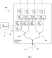
- the communications network optical apparatus 900 comprises two optical modules - optical module 120 and optical module two 120(2) - and a variable power coupler 910.
- the variable power coupler may, for example, be a directional coupler with thermo-optic variation of the refractive index or may be a double micro-ring coupler.
- the variable power coupler is configured to receive the external optical signal 132 and is configured to power split the external optical signal to send a first portion of the external optical signal to the optical module 120 and a second portion of the external optical signal to the second optical module 120(2).
- the external optical signal 132 can therefore be used to serve both optical modules.
- the controller 140 is caused to generate a further control signal 912 to provide a control command to the variable power coupler.
- the control command is configured to set the percentage of received external optical signal that is routed to each of the optical modules.
- the optical modules are independent, therefore a thermal protection condition may occur at different times for each module.
- the variable power coupler is operable to send a portion of the external optical signal to the optical module where it is needed.
- the external optical signal is split and distributed in a single step using the variable power coupler that acts as a switch that also regulates the percentage of laser power that passes from one waveguide to the other.
- variable coupler in this case is a variant of switch node in the switch matrix used for the routing of the light from the external laser sources towards the modules.
- the communications network optical apparatus 950 further comprises an external laser 152 arranged to generate the external optical signal 132.
- the laser power of the external laser 152 may be variable.
- the controller is operable to respond to requests by simultaneously controlling the external laser power, to serve the totality of the optical modules, and configuring the variable coupler to send the required fraction of external laser power to each optical module.
- controller is further operative to perform further operations including:
- the communications network optical apparatus 1000 comprises a plurality of optical modules 120 and an optical switch apparatus 1020.
- the optical switch apparatus is configured to receive a plurality of external optical signals 132.
- the controller 1040 is operative to receive temperature reporting signals from the optical modules 120 and to determine that a thermal protection condition exists at an optical module based on the temperature of its internal lasers 124.
- the control signals are further configured to cause the optical switch apparatus to route one of the external optical signals to the optical module having the thermal protection condition. It will be understood that a thermal protection condition may exist at more than one optical module at the same time and the control signals are configured to cause the optical switch apparatus to route a respective external optical signal to each optical module at which a thermal protection condition exists.
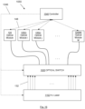
- Figure 14 illustrates the logical scheme of an optical switch apparatus 1120, external lasers 152 and optical modules 120 of a further embodiment of communications network optical apparatus similar to the apparatus 1000 illustrated in Figure 13 .
- the optical switch apparatus 1120 is configurable to conditionally connect a set of N external lasers 152 to M optical modules 120.
- the optical switch apparatus 1120 comprises a plurality of optical switch nodes 1124 which may be configured to route an external optical signal from an external laser 152 to an optical module 120.
- a 1:K optical splitter 1122 is provided between each external laser 152 and the optical switch nodes, to power split the external optical signal from each external laser 152.
- the outputs of the optical switch apparatus are connected to the M optical modules 120 by M optical fibers 1126.
- Figure 15 illustrates the logical scheme of an optical switch apparatus 1220, external lasers 152 and optical modules 120 of a further embodiment of communications network optical apparatus similar to the apparatus 1000 illustrated in Figure 13 .
- the optical switch apparatus 1220 is configurable to conditionally connect a set of N variable power external lasers 1152 to M optical modules 120.
- the optical switch apparatus 1220 comprises a plurality of optical switch nodes 1222 which may be configured to route an external optical signal from an external laser 1152 to an optical module 120.
- Each optical switch node 1222 is configurable to route a portion of an external optical signal received from a respective external laser 1152 to a respective optical module 120.
- a variable power external laser may therefore be used to service a variable number of optical modules. Up to K optical switch nodes may be activated at the same time.
- the outputs of the optical switch apparatus are connected to the M optical modules 120 by M optical fibers 1126.
- an optical module 120 is a co-packaged optics, CPO, optical module.
- an optical module 120 is provided in a Radio Unit of a communications network.
- a Radio Unit typically there is no forced ventilation for cooling; the operating temperature is dependent on the environment temperature and is directly related to the power dissipation of the unit.
- the communications network optical apparatus 1050 further comprises a pool of N external lasers 1152 arranged to generate the external optical signals 132.
- the external lasers 1010 and the optical switch apparatus 1020 are located remote from the optical modules 120.
- each of the optical modules 120 comprises a plurality of internal lasers 124, one or more of which may be handed over to an external optical signal when a thermal protection condition exists.
- the controller 1040 is caused to perform operations to control handover from an internal laser 124 to an external laser 1152 and subsequent off of the internal laser.
- the handover comprises the following functions:
- the controller 1040 is caused to perform operations including:
- the choice of external laser may be based on criteria including, for example: distance, power, and operating wavelength.
- the external lasers may be located in proximity to the optical modules (from some cm to meters) or very far in a remote location up to km away from the optical modules to be served.
- the external laser could be connected to the module via a polarization maintaining fiber, so to avoid addressing polarization diversity in the photonic chip of the module.
- polarization agnostic laser sources are preferrable, such as the remote laser source described in US10014943B2 .
- the pool of external lasers provides a number of external sources N to a set of M optical modules 120 via switching of optical switch nodes of the optical switch apparatus 1020.
- the choice of N and M depends on the statistics of the protection condition and the number of internal lasers in each optical module.
- the response of the optical switch apparatus is not time-critical, since the handover will not take place until the external optical signal has reached the optical module.
- the external lasers 1152 can be a high-power laser, that can be split to serve many optical channels (i.e. optical modulators) or a low power laser to serve a single channel.
- the external laser can be switched on following detection of the thermal protection condition.
- extra controls are needed to deliver the required optical power to each optical module independently. These controls may include the external laser power variation and variable optical power splitting described above.
- control is simpler as the external optical signal can be simply routed towards the respective optical modulator of a single optical channel and switched off when not in use.
- the external laser may be a wavelength tunable laser to increase flexibility.
- the handover from an internal optical signal generated by an internal laser to an external optical signal generated by an external laser is performed such that the optical power input to the respective optical modulator is maintained, with a preference towards a slight increase of optical power in the case of a gradual power up of the external laser or when the internal laser switch off and external laser switch on cannot be synchronized and symmetric.
- the controller 1040 is caused to generate control signals to switch from/to the use of the light of the external source and the internal laser gradually, with a coexistence of the two light inputs to feed the optical transmitter, or to exclude the internal laser at the inset of the external laser.
- the apparatus 1050 may exploit known control systems used to control the average optical power output by an optical module. For example, automated power control loops that change the bias current of the internal laser 124 in response to the light power received from a monitor photodiode, e.g. where the bias current is changed to maintain the photo-diode current. This type of control is generally present in optical modules to compensate for temperature variation and aging of the laser.
- the controller 1040 may be caused to perform operations including:
- the optical tap 408, 510, 612 within the optical routing device 400, 500, 600 sends a % of light to a monitor photodiode that detects the light intensity increase caused by the merging of the external optical signal with the internal optical signal.
- the controller 1040 is further caused to general a second control signal comprising power control commands to cause a decrease of the bias current of the internal laser in response to the photodiode signal.
- the M optical modules 120 are provided within a cluster of Radio Units, sharing the pool of N external lasers 1152.
- the external lasers are connected to the Radio Units with optical fibers of up to 2-3 Km of length.
- an embodiment provides a method 1400 of providing optical signals for an optical module in a communications network.
- the method comprises steps of:
Landscapes
- Physics & Mathematics (AREA)
- Electromagnetism (AREA)
- Engineering & Computer Science (AREA)
- Optics & Photonics (AREA)
- Computer Networks & Wireless Communication (AREA)
- Signal Processing (AREA)
- Plasma & Fusion (AREA)
- General Physics & Mathematics (AREA)
- Optical Communication System (AREA)
Claims (15)
- Optische Kommunikationsnetzwerkvorrichtung (100, 150, 200, 250, 800, 850, 900, 950, 1000, 1050), umfassend:
ein optisches Modul (120), umfassend:optische Modulatoren (122), die dazu angeordnet sind, optische Signale zu modulieren;interne Laser (124), die dazu angeordnet sind, interne optische Signale zu erzeugen, die durch die optischen Modulatoren zu modulieren sind;einen Eingangsanschluss (126), der dazu angeordnet ist, ein externes optisches Signal (132) von einem externen Laser zu empfangen;optische Routingeinrichtungen (128, 400, 500, 600, 710), die dazu angeordnet sind, interne optische Signale von internen Lasern an optische Modulatoren weiterzuleiten und ein externes optisches Signal von dem Eingangsanschluss an mindestens einen der optischen Modulatoren weiterzuleiten; undeinen Temperatursensor (130), der dazu angeordnet ist, eine Temperatur der internen Laser zu erfassen und ein Temperaturmeldesignal zu erzeugen; undeine Steuerung (140, 1040), umfassend Verarbeitungsschaltungen (142) und einen Speicher (144), der Anweisungen enthält, die durch die Verarbeitungsschaltungen ausführbar sind, wodurch die Steuerung zu Folgendem einsatzbereit ist:Empfangen des Temperaturmeldesignals;Bestimmen, dass eine thermische Schutzbedingung vorliegt, basierend auf der Temperatur der internen Laser; undals Reaktion auf das Bestimmen, Erzeugen von Steuersignalen (146, 148, 1046), die dazu konfiguriert sind, zu veranlassen, dass das externe optische Signal an mindestens einen optischen Modulator bereitgestellt wird und zu veranlassen, dass eine Betriebsleistung mindestens eines jeweiligen internen Lasers reduziert wird. - Optische Kommunikationsnetzwerkvorrichtung nach Anspruch 1, wobei die Steuersignale Folgendes umfassen:ein erstes Steuersignal (146, 1046) zum Bereitstellen von Leistungssteuerbefehlen an einen externen Laser (124); undein zweites Steuersignal (148) zum Bereitstellen von Leistungssteuerbefehlen an den mindestens einen internen Laser;und wobei die Steuerung zu Folgendem einsatzbereit ist:Erzeugen des ersten Steuersignals, um einen Einschalt-Steuerbefehl an den externen Laser als Reaktion auf das Bestimmen, dass eine thermische Schutzbedingung vorliegt, bereitzustellen; undanschließendes Erzeugen des zweiten Steuersignals, um mindestens einen Leistungssteuerbefehl bereitzustellen, der dazu konfiguriert ist, zu veranlassen, dass die Betriebsleistung des mindestens einen jeweiligen internen Lasers reduziert wird.
- Optische Kommunikationsnetzwerkvorrichtung nach Anspruch 1 oder Anspruch 2, wobei die Betriebsleistung des mindestens einen jeweiligen internen Lasers (124) durch Abschalten der Betriebsleistung, durch schrittweises Reduzieren der Betriebsleistung und nachfolgendes Abschalten der Betriebsleistung oder durch schrittweises Reduzieren der Betriebsleistung auf Null reduziert wird.
- Optische Kommunikationsnetzwerkvorrichtung nach Anspruch 2 oder Anspruch 3, wobei das optische Modul (120) ferner einen optischen Abzweig (202) umfasst, der dazu konfiguriert ist, einen Teil (x) eines externen optischen Signals (132), das an dem Eingangsanschluss (126) empfangen wird, an den mindestens einen jeweiligen internen Laser (124) für ein Injection-Locking des mindestens einen internen Lasers mit dem externen optischen Signal weiterzuleiten, und wobei das zweite Steuersignal anschließend an das Injection-Locking erzeugt wird.
- Optische Kommunikationsnetzwerkvorrichtung nach einem der Ansprüche 1 bis 3, wobei das externe optische Signal (132) eine erste Frequenz aufweist und die internen optischen Signale Frequenzen aufweisen, die sich von der ersten Frequenz um einen Frequenzunterschied unterscheiden, der größer ist als eine festgelegte Erfassungsbandbreite.
- Optische Kommunikationsnetzwerkvorrichtung nach einem der Ansprüche 2 bis 5, wobei:die optischen Routingeinrichtungen (500, 600) einen ersten optischen Wellenleiter (502, 602), der mit einem optischen Modulator (122) gekoppelt ist, einen zweiten optischen Wellenleiter (504, 604), der mit einem internen Laser (124) gekoppelt ist, einen dritten optischen Wellenleiter (506, 606), der mit dem Eingangsanschluss gekoppelt ist, und mindestens einen gerichteten Phasenverschiebungskoppler (508, 608, 610) zum Koppeln des zweiten optischen Wellenleiters mit dem ersten optischen Wellenleiter oder des dritten optischen Wellenleiters mit dem ersten optischen Wellenleiter umfassen;die Steuersignale ferner ein drittes Steuersignal (520, 620) zum Bereitstellen von Steuerbefehlen an den mindestens einen gerichteten Phasenverschiebungskoppler umfassen; und die Steuerung (140) dazu veranlasst wird, das dritte Steuersignal nach Erzeugen des ersten Steuersignals zu erzeugen, wobei das dritte Steuersignal dazu konfiguriert ist, Steuerbefehle für Folgendes bereitzustellen:Veranlassen des mindestens einen gerichteten Phasenverschiebungskopplers, das interne optische Signal in den ersten optischen Wellenleiter mit einer ersten Phase einzukoppeln;Veranlassen des mindestens einen gerichteten Phasenverschiebungskopplers, das Einkoppeln des internen optischen Signals in den ersten optischen Wellenleiter zu beenden; undVeranlassen des mindestens einen gerichteten Phasenverschiebungskopplers, das externe optische Signal in den ersten optischen Wellenleiter mit der ersten Phase einzukoppeln.
- Optische Kommunikationsnetzwerkvorrichtung nach Anspruch 6, wobei das dritte Steuersignal (520, 620) zusätzlich dazu konfiguriert ist, weitere Steuerbefehle für Folgendes bereitzustellen:Veranlassen des mindestens einen gerichteten Phasenverschiebungskopplers, das Einkoppeln des internen optischen Signals in den ersten optischen Wellenleiter allmählich auf Null zu reduzieren; undVeranlassen des mindestens einen gerichteten Phasenverschiebungskopplers, das Einkoppeln des externen optischen Signals in den ersten optischen Wellenleiter mit der ersten Phase allmählich zu steigern.
- Optische Kommunikationsnetzwerkvorrichtung nach einem der Ansprüche 1 bis 3, wobei die optischen Routingeinrichtungen einen rein optischen Schalter (710) umfassen, der einen ersten Eingang (712), der mit einem internen Laser (124) verbunden ist, einen zweiten Eingang (714), der mit dem Eingangsanschluss (126) verbunden ist und einen Ausgang (716), der mit einem optischen Modulator (122) verbunden ist, aufweist; und
das optische Modul ferner einen optischen Abzweig (726) umfasst, der dazu konfiguriert ist, einen Teil des externen optischen Signals, das an dem Eingangsanschluss des optischen Moduls empfangen wird, an den rein optischen Schalter als ein Schaltsignal für den rein optischen Schalter weiterzuleiten, wobei der rein optische Schalter eine erste Schaltbedingung, bei welcher der erste Eingang mit dem Ausgang verbunden ist, und eine zweite Schaltbedingung, bei welcher der zweite Eingang mit dem Ausgang verbunden ist, aufweist und wobei der rein optische Schalter dazu angeordnet ist, von der ersten Schaltbedingung in die zweite Schaltbedingung als Reaktion auf den Empfang eines solchen Schaltsignals umzuschalten. - Optische Kommunikationsnetzwerkvorrichtung nach einem der vorhergehenden Ansprüche, ferner umfassend ein zweites optisches Modul (120(2)) und einen variablen Leistungskoppler (910), der dazu konfiguriert ist, das externe optische Signal von dem externen Laser (110) zu empfangen und der dazu konfiguriert ist, die Leistung des externen optischen Signals aufzuteilen, um einen ersten Teil des externen optischen Signals an das optische Modul (120) und einen zweiten Teil des externen optischen Signals an das zweite optische Modul (120(2)) zu senden.
- Optische Kommunikationsnetzwerkvorrichtung nach einem der vorhergehenden Ansprüche, wobei die Steuerung (140, 1040) ferner zu Folgendem einsatzbereit ist:Empfangen eines weiteren Temperaturmeldesignals;Bestimmen, dass eine thermische Schutzbedingung nicht mehr vorliegt, basierend auf der Temperatur der internen Laser; undals Reaktion auf das Bestimmen, Erzeugen von Steuersignalen, die dazu konfiguriert sind, das Bereitstellen des externen optischen Signals an den mindestens einen optischen Modulator zu beenden und zu veranlassen, dass die Reduzierung der Betriebsleistung des mindestens einen jeweiligen internen Lasers rückgängig gemacht wird.
- Optische Kommunikationsnetzwerkvorrichtung nach einem der vorhergehenden Ansprüche, wobei die Vorrichtung (1000) Folgendes umfasst:eine Vielzahl der optischen Module (120); undeine optische Schaltvorrichtung (1020, 1120, 1220), die dazu konfiguriert ist, eine Vielzahl der externen optischen Signale von einer Vielzahl von externen Lasern zu empfangen,und wobei die Steuerung (1040) dazu betriebsbereit ist, Temperaturmeldesignale von der Vielzahl der optischen Module zu empfangen und zu bestimmen, dass eine thermische Schutzbedingung bei einem der optischen Module der Vielzahl der optischen Module vorliegt, basierend auf der Temperatur seiner internen Laser, und wobei die Steuersignale ferner dazu konfiguriert sind, die optische Schaltvorrichtung dazu zu veranlassen, eines der externen optischen Signale an das optische Modul, das die thermische Schutzbedingung aufweist, weiterzuleiten.
- Optische Kommunikationsnetzwerkvorrichtung nach einem der vorhergehenden Ansprüche, ferner umfassend mindestens einen externen Laser (152, 1152), der dazu angeordnet ist, mindestens ein externes optisches Signal (132) zu erzeugen.
- Optische Kommunikationsnetzwerkvorrichtung nach einem der vorhergehenden Ansprüche, wobei ein optisches Modul (120) ein Co-Packaged-Optics-Modul, CPO-Modul, ist.
- Optische Kommunikationsnetzwerkvorrichtung nach einem der vorhergehenden Ansprüche, wobei ein optisches Modul (120) in einer Funkeinheit bereitgestellt ist.
- Verfahren (1400) zum Bereitstellen optischer Signale für ein optisches Modul in einem Kommunikationsnetzwerk, wobei das Verfahren folgende Schritte umfasst:Erzeugen (1402) eines internen optischen Signals an einen internen Laser des optischen Moduls;Bereitstellen (1404) des internen optischen Signals an einen optischen Modulator des optischen Moduls zur optischen Modulation;Überwachen (1406) einer Temperatur des internen Lasers;Bestimmen (1408), dass eine thermische Schutzbedingung vorliegt, basierend auf der Temperatur des internen Lasers; undals Reaktion auf das Bestimmen, Veranlassen (1410), dass ein externes optisches Signal an den optischen Modulator bereitgestellt wird und Veranlassen, dass eine Betriebsleistung des internen Lasers reduziert wird.
Applications Claiming Priority (1)
| Application Number | Priority Date | Filing Date | Title |
|---|---|---|---|
| PCT/EP2021/071573 WO2023011699A1 (en) | 2021-08-02 | 2021-08-02 | Communications network optical apparatus and method of providing an optical signal |
Publications (2)
| Publication Number | Publication Date |
|---|---|
| EP4381630A1 EP4381630A1 (de) | 2024-06-12 |
| EP4381630B1 true EP4381630B1 (de) | 2025-05-28 |
Family
ID=77180044
Family Applications (1)
| Application Number | Title | Priority Date | Filing Date |
|---|---|---|---|
| EP21749656.1A Active EP4381630B1 (de) | 2021-08-02 | 2021-08-02 | Optische kommunikationsnetzwerkvorrichtung und verfahren zur bereitstellung eines optischen signals |
Country Status (3)
| Country | Link |
|---|---|
| US (1) | US12580661B2 (de) |
| EP (1) | EP4381630B1 (de) |
| WO (1) | WO2023011699A1 (de) |
Families Citing this family (2)
| Publication number | Priority date | Publication date | Assignee | Title |
|---|---|---|---|---|
| US20250189864A1 (en) * | 2023-12-08 | 2025-06-12 | Nvidia Corp. | Laser sparing architectures for multi-wavelength laser arrays |
| CN118970618A (zh) * | 2024-07-18 | 2024-11-15 | 四川泰瑞创通讯技术股份有限公司 | 激光器光功率的控制方法、设备、存储介质及产品 |
Family Cites Families (7)
| Publication number | Priority date | Publication date | Assignee | Title |
|---|---|---|---|---|
| CN101009530B (zh) * | 2006-01-23 | 2012-02-15 | 华为技术有限公司 | 支持组播类业务的无源光网络、复用/解复用器及方法 |
| US8699533B1 (en) * | 2009-02-23 | 2014-04-15 | Cirrex Systems, Llc | Method and system for managing thermally sensitive optical devices |
| WO2015144224A1 (en) | 2014-03-27 | 2015-10-01 | Telefonaktiebolaget L M Ericsson (Publ) | Optical source, communications network optical apparatus and method of providing an optical signal |
| US9882336B2 (en) * | 2015-09-29 | 2018-01-30 | Hisense Broadband Multimedia Technologies Co., Ltd. | Optical module |
| US10277327B2 (en) | 2016-12-28 | 2019-04-30 | Calix Inc. | Methods and apparatus for improving reliability of an optical device using auxiliary lasers in a photonic integrated circuit |
| US10812181B2 (en) * | 2018-11-16 | 2020-10-20 | Ii-Vi Delaware Inc. | Light source redundancy in optical communication devices |
| KR20210058312A (ko) * | 2019-11-14 | 2021-05-24 | 한국전자통신연구원 | 무선 신호 송신 장치 및 무선 신호 수신 장치 |
-
2021
- 2021-08-02 EP EP21749656.1A patent/EP4381630B1/de active Active
- 2021-08-02 US US18/290,856 patent/US12580661B2/en active Active
- 2021-08-02 WO PCT/EP2021/071573 patent/WO2023011699A1/en not_active Ceased
Also Published As
| Publication number | Publication date |
|---|---|
| US20240259106A1 (en) | 2024-08-01 |
| WO2023011699A1 (en) | 2023-02-09 |
| US12580661B2 (en) | 2026-03-17 |
| EP4381630A1 (de) | 2024-06-12 |
Similar Documents
| Publication | Publication Date | Title |
|---|---|---|
| US7536067B2 (en) | Photonic integrated circuit device and elements thereof | |
| US11451301B2 (en) | Light source backup method, apparatus, and system | |
| EP3289407B1 (de) | Polarisationsunabhängiger, reflektierender modulator | |
| US20090196598A1 (en) | Optical source link transmission device and method | |
| WO2016210362A1 (en) | Optical interconnect for switch applications | |
| EP4340253A1 (de) | Kommunikationssystem, sender und kommunikationsverfahren | |
| US11606148B2 (en) | Polarization processing apparatus, optical transceiver, and optical polarization processing method | |
| EP4381630B1 (de) | Optische kommunikationsnetzwerkvorrichtung und verfahren zur bereitstellung eines optischen signals | |
| US10178452B2 (en) | Optical interconnect having optical splitters and modulators integrated on same chip | |
| US12156310B2 (en) | Optical source switching method and apparatus | |
| US7106965B2 (en) | Wavelength division multiplex transmission system and communication device | |
| US12401423B2 (en) | Optical network, network management device, and network management method | |
| JP5457557B2 (ja) | 波長分割多重アクセスネットワークを動作させるための装置および方法 | |
| US20070071447A1 (en) | Optical receiving apparatus and dispersion compensating method therein | |
| JPWO2009060522A1 (ja) | 光送受信モジュールおよびその管理制御方法,光送受信装置ならびに波長多重光送受信装置 | |
| WO2014017083A1 (ja) | 光伝送装置およびその制御方法 | |
| US20020168129A1 (en) | System and method for bridge and roll in a photonic switch | |
| WO2022257751A1 (zh) | 一种交换机以及通信系统 | |
| JP2008199450A (ja) | 光アクセスシステム | |
| EP4713744A1 (de) | Verfahren und system für co-verpackte optik | |
| JP2014110573A (ja) | 光伝送システム及び回線切替えシステム |
Legal Events
| Date | Code | Title | Description |
|---|---|---|---|
| STAA | Information on the status of an ep patent application or granted ep patent |
Free format text: STATUS: UNKNOWN |
|
| STAA | Information on the status of an ep patent application or granted ep patent |
Free format text: STATUS: THE INTERNATIONAL PUBLICATION HAS BEEN MADE |
|
| PUAI | Public reference made under article 153(3) epc to a published international application that has entered the european phase |
Free format text: ORIGINAL CODE: 0009012 |
|
| STAA | Information on the status of an ep patent application or granted ep patent |
Free format text: STATUS: REQUEST FOR EXAMINATION WAS MADE |
|
| 17P | Request for examination filed |
Effective date: 20240227 |
|
| AK | Designated contracting states |
Kind code of ref document: A1 Designated state(s): AL AT BE BG CH CY CZ DE DK EE ES FI FR GB GR HR HU IE IS IT LI LT LU LV MC MK MT NL NO PL PT RO RS SE SI SK SM TR |
|
| DAV | Request for validation of the european patent (deleted) | ||
| DAX | Request for extension of the european patent (deleted) | ||
| GRAP | Despatch of communication of intention to grant a patent |
Free format text: ORIGINAL CODE: EPIDOSNIGR1 |
|
| STAA | Information on the status of an ep patent application or granted ep patent |
Free format text: STATUS: GRANT OF PATENT IS INTENDED |
|
| INTG | Intention to grant announced |
Effective date: 20250224 |
|
| GRAS | Grant fee paid |
Free format text: ORIGINAL CODE: EPIDOSNIGR3 |
|
| GRAA | (expected) grant |
Free format text: ORIGINAL CODE: 0009210 |
|
| STAA | Information on the status of an ep patent application or granted ep patent |
Free format text: STATUS: THE PATENT HAS BEEN GRANTED |
|
| AK | Designated contracting states |
Kind code of ref document: B1 Designated state(s): AL AT BE BG CH CY CZ DE DK EE ES FI FR GB GR HR HU IE IS IT LI LT LU LV MC MK MT NL NO PL PT RO RS SE SI SK SM TR |
|
| REG | Reference to a national code |
Ref country code: GB Ref legal event code: FG4D |
|
| REG | Reference to a national code |
Ref country code: CH Ref legal event code: EP |
|
| REG | Reference to a national code |
Ref country code: IE Ref legal event code: FG4D Ref country code: DE Ref legal event code: R096 Ref document number: 602021031451 Country of ref document: DE |
|
| REG | Reference to a national code |
Ref country code: NL Ref legal event code: MP Effective date: 20250528 |
|
| PG25 | Lapsed in a contracting state [announced via postgrant information from national office to epo] |
Ref country code: ES Free format text: LAPSE BECAUSE OF FAILURE TO SUBMIT A TRANSLATION OF THE DESCRIPTION OR TO PAY THE FEE WITHIN THE PRESCRIBED TIME-LIMIT Effective date: 20250528 Ref country code: FI Free format text: LAPSE BECAUSE OF FAILURE TO SUBMIT A TRANSLATION OF THE DESCRIPTION OR TO PAY THE FEE WITHIN THE PRESCRIBED TIME-LIMIT Effective date: 20250528 |
|
| PGFP | Annual fee paid to national office [announced via postgrant information from national office to epo] |
Ref country code: DE Payment date: 20250827 Year of fee payment: 5 |
|
| REG | Reference to a national code |
Ref country code: LT Ref legal event code: MG9D |
|
| PG25 | Lapsed in a contracting state [announced via postgrant information from national office to epo] |
Ref country code: NO Free format text: LAPSE BECAUSE OF FAILURE TO SUBMIT A TRANSLATION OF THE DESCRIPTION OR TO PAY THE FEE WITHIN THE PRESCRIBED TIME-LIMIT Effective date: 20250828 Ref country code: GR Free format text: LAPSE BECAUSE OF FAILURE TO SUBMIT A TRANSLATION OF THE DESCRIPTION OR TO PAY THE FEE WITHIN THE PRESCRIBED TIME-LIMIT Effective date: 20250829 |
|
| PG25 | Lapsed in a contracting state [announced via postgrant information from national office to epo] |
Ref country code: NL Free format text: LAPSE BECAUSE OF FAILURE TO SUBMIT A TRANSLATION OF THE DESCRIPTION OR TO PAY THE FEE WITHIN THE PRESCRIBED TIME-LIMIT Effective date: 20250528 Ref country code: PL Free format text: LAPSE BECAUSE OF FAILURE TO SUBMIT A TRANSLATION OF THE DESCRIPTION OR TO PAY THE FEE WITHIN THE PRESCRIBED TIME-LIMIT Effective date: 20250528 |
|
| PG25 | Lapsed in a contracting state [announced via postgrant information from national office to epo] |
Ref country code: BG Free format text: LAPSE BECAUSE OF FAILURE TO SUBMIT A TRANSLATION OF THE DESCRIPTION OR TO PAY THE FEE WITHIN THE PRESCRIBED TIME-LIMIT Effective date: 20250528 |
|
| PGFP | Annual fee paid to national office [announced via postgrant information from national office to epo] |
Ref country code: GB Payment date: 20250827 Year of fee payment: 5 |
|
| PG25 | Lapsed in a contracting state [announced via postgrant information from national office to epo] |
Ref country code: HR Free format text: LAPSE BECAUSE OF FAILURE TO SUBMIT A TRANSLATION OF THE DESCRIPTION OR TO PAY THE FEE WITHIN THE PRESCRIBED TIME-LIMIT Effective date: 20250528 |
|
| PGFP | Annual fee paid to national office [announced via postgrant information from national office to epo] |
Ref country code: AT Payment date: 20251020 Year of fee payment: 5 |
|
| PG25 | Lapsed in a contracting state [announced via postgrant information from national office to epo] |
Ref country code: RS Free format text: LAPSE BECAUSE OF FAILURE TO SUBMIT A TRANSLATION OF THE DESCRIPTION OR TO PAY THE FEE WITHIN THE PRESCRIBED TIME-LIMIT Effective date: 20250828 |
|
| PG25 | Lapsed in a contracting state [announced via postgrant information from national office to epo] |
Ref country code: IS Free format text: LAPSE BECAUSE OF FAILURE TO SUBMIT A TRANSLATION OF THE DESCRIPTION OR TO PAY THE FEE WITHIN THE PRESCRIBED TIME-LIMIT Effective date: 20250928 |
|
| PG25 | Lapsed in a contracting state [announced via postgrant information from national office to epo] |
Ref country code: LV Free format text: LAPSE BECAUSE OF FAILURE TO SUBMIT A TRANSLATION OF THE DESCRIPTION OR TO PAY THE FEE WITHIN THE PRESCRIBED TIME-LIMIT Effective date: 20250528 |
|
| REG | Reference to a national code |
Ref country code: AT Ref legal event code: MK05 Ref document number: 1799257 Country of ref document: AT Kind code of ref document: T Effective date: 20250528 |
|
| PG25 | Lapsed in a contracting state [announced via postgrant information from national office to epo] |
Ref country code: DK Free format text: LAPSE BECAUSE OF FAILURE TO SUBMIT A TRANSLATION OF THE DESCRIPTION OR TO PAY THE FEE WITHIN THE PRESCRIBED TIME-LIMIT Effective date: 20250528 Ref country code: AT Free format text: LAPSE BECAUSE OF FAILURE TO SUBMIT A TRANSLATION OF THE DESCRIPTION OR TO PAY THE FEE WITHIN THE PRESCRIBED TIME-LIMIT Effective date: 20250528 Ref country code: SM Free format text: LAPSE BECAUSE OF FAILURE TO SUBMIT A TRANSLATION OF THE DESCRIPTION OR TO PAY THE FEE WITHIN THE PRESCRIBED TIME-LIMIT Effective date: 20250528 |
|
| PG25 | Lapsed in a contracting state [announced via postgrant information from national office to epo] |
Ref country code: CZ Free format text: LAPSE BECAUSE OF FAILURE TO SUBMIT A TRANSLATION OF THE DESCRIPTION OR TO PAY THE FEE WITHIN THE PRESCRIBED TIME-LIMIT Effective date: 20250528 |
|
| PG25 | Lapsed in a contracting state [announced via postgrant information from national office to epo] |
Ref country code: EE Free format text: LAPSE BECAUSE OF FAILURE TO SUBMIT A TRANSLATION OF THE DESCRIPTION OR TO PAY THE FEE WITHIN THE PRESCRIBED TIME-LIMIT Effective date: 20250528 |
|
| PG25 | Lapsed in a contracting state [announced via postgrant information from national office to epo] |
Ref country code: SK Free format text: LAPSE BECAUSE OF FAILURE TO SUBMIT A TRANSLATION OF THE DESCRIPTION OR TO PAY THE FEE WITHIN THE PRESCRIBED TIME-LIMIT Effective date: 20250528 |
|
| PG25 | Lapsed in a contracting state [announced via postgrant information from national office to epo] |
Ref country code: IT Free format text: LAPSE BECAUSE OF FAILURE TO SUBMIT A TRANSLATION OF THE DESCRIPTION OR TO PAY THE FEE WITHIN THE PRESCRIBED TIME-LIMIT Effective date: 20250528 |
|
| PG25 | Lapsed in a contracting state [announced via postgrant information from national office to epo] |
Ref country code: RO Free format text: LAPSE BECAUSE OF FAILURE TO SUBMIT A TRANSLATION OF THE DESCRIPTION OR TO PAY THE FEE WITHIN THE PRESCRIBED TIME-LIMIT Effective date: 20250528 |