EP4379974A1 - Rotary connector device and method for manufacturing rotary connector device - Google Patents
Rotary connector device and method for manufacturing rotary connector device Download PDFInfo
- Publication number
- EP4379974A1 EP4379974A1 EP22849475.3A EP22849475A EP4379974A1 EP 4379974 A1 EP4379974 A1 EP 4379974A1 EP 22849475 A EP22849475 A EP 22849475A EP 4379974 A1 EP4379974 A1 EP 4379974A1
- Authority
- EP
- European Patent Office
- Prior art keywords
- stator
- connector
- electrical connector
- rotational axis
- electrical
- Prior art date
- Legal status (The legal status is an assumption and is not a legal conclusion. Google has not performed a legal analysis and makes no representation as to the accuracy of the status listed.)
- Pending
Links
Images






Classifications
-
- H—ELECTRICITY
- H01—ELECTRIC ELEMENTS
- H01R—ELECTRICALLY-CONDUCTIVE CONNECTIONS; STRUCTURAL ASSOCIATIONS OF A PLURALITY OF MUTUALLY-INSULATED ELECTRICAL CONNECTING ELEMENTS; COUPLING DEVICES; CURRENT COLLECTORS
- H01R39/00—Rotary current collectors, distributors or interrupters
- H01R39/64—Devices for uninterrupted current collection
-
- H—ELECTRICITY
- H01—ELECTRIC ELEMENTS
- H01R—ELECTRICALLY-CONDUCTIVE CONNECTIONS; STRUCTURAL ASSOCIATIONS OF A PLURALITY OF MUTUALLY-INSULATED ELECTRICAL CONNECTING ELEMENTS; COUPLING DEVICES; CURRENT COLLECTORS
- H01R35/00—Flexible or turnable line connectors, i.e. the rotation angle being limited
- H01R35/04—Turnable line connectors with limited rotation angle with frictional contact members
-
- H—ELECTRICITY
- H01—ELECTRIC ELEMENTS
- H01R—ELECTRICALLY-CONDUCTIVE CONNECTIONS; STRUCTURAL ASSOCIATIONS OF A PLURALITY OF MUTUALLY-INSULATED ELECTRICAL CONNECTING ELEMENTS; COUPLING DEVICES; CURRENT COLLECTORS
- H01R35/00—Flexible or turnable line connectors, i.e. the rotation angle being limited
- H01R35/02—Flexible line connectors without frictional contact members
- H01R35/025—Flexible line connectors without frictional contact members having a flexible conductor wound around a rotation axis
-
- B—PERFORMING OPERATIONS; TRANSPORTING
- B60—VEHICLES IN GENERAL
- B60R—VEHICLES, VEHICLE FITTINGS, OR VEHICLE PARTS, NOT OTHERWISE PROVIDED FOR
- B60R16/00—Electric or fluid circuits specially adapted for vehicles and not otherwise provided for; Arrangement of elements of electric or fluid circuits specially adapted for vehicles and not otherwise provided for
- B60R16/02—Electric or fluid circuits specially adapted for vehicles and not otherwise provided for; Arrangement of elements of electric or fluid circuits specially adapted for vehicles and not otherwise provided for electric constitutive elements
- B60R16/023—Electric or fluid circuits specially adapted for vehicles and not otherwise provided for; Arrangement of elements of electric or fluid circuits specially adapted for vehicles and not otherwise provided for electric constitutive elements for transmission of signals between vehicle parts or subsystems
- B60R16/027—Electric or fluid circuits specially adapted for vehicles and not otherwise provided for; Arrangement of elements of electric or fluid circuits specially adapted for vehicles and not otherwise provided for electric constitutive elements for transmission of signals between vehicle parts or subsystems between relatively movable parts of the vehicle, e.g. between steering wheel and column
-
- H—ELECTRICITY
- H01—ELECTRIC ELEMENTS
- H01R—ELECTRICALLY-CONDUCTIVE CONNECTIONS; STRUCTURAL ASSOCIATIONS OF A PLURALITY OF MUTUALLY-INSULATED ELECTRICAL CONNECTING ELEMENTS; COUPLING DEVICES; CURRENT COLLECTORS
- H01R13/00—Details of coupling devices of the kinds covered by groups H01R12/70 or H01R24/00 - H01R33/00
- H01R13/46—Bases; Cases
- H01R13/50—Bases; Cases formed as an integral body
- H01R13/501—Bases; Cases formed as an integral body comprising an integral hinge or a frangible part
-
- H—ELECTRICITY
- H01—ELECTRIC ELEMENTS
- H01R—ELECTRICALLY-CONDUCTIVE CONNECTIONS; STRUCTURAL ASSOCIATIONS OF A PLURALITY OF MUTUALLY-INSULATED ELECTRICAL CONNECTING ELEMENTS; COUPLING DEVICES; CURRENT COLLECTORS
- H01R13/00—Details of coupling devices of the kinds covered by groups H01R12/70 or H01R24/00 - H01R33/00
- H01R13/46—Bases; Cases
- H01R13/516—Means for holding or embracing insulating body, e.g. casing, hoods
-
- H—ELECTRICITY
- H01—ELECTRIC ELEMENTS
- H01R—ELECTRICALLY-CONDUCTIVE CONNECTIONS; STRUCTURAL ASSOCIATIONS OF A PLURALITY OF MUTUALLY-INSULATED ELECTRICAL CONNECTING ELEMENTS; COUPLING DEVICES; CURRENT COLLECTORS
- H01R43/00—Apparatus or processes specially adapted for manufacturing, assembling, maintaining, or repairing of line connectors or current collectors or for joining electric conductors
- H01R43/20—Apparatus or processes specially adapted for manufacturing, assembling, maintaining, or repairing of line connectors or current collectors or for joining electric conductors for assembling or disassembling contact members with insulating base, case or sleeve
-
- H—ELECTRICITY
- H01—ELECTRIC ELEMENTS
- H01R—ELECTRICALLY-CONDUCTIVE CONNECTIONS; STRUCTURAL ASSOCIATIONS OF A PLURALITY OF MUTUALLY-INSULATED ELECTRICAL CONNECTING ELEMENTS; COUPLING DEVICES; CURRENT COLLECTORS
- H01R43/00—Apparatus or processes specially adapted for manufacturing, assembling, maintaining, or repairing of line connectors or current collectors or for joining electric conductors
- H01R43/26—Apparatus or processes specially adapted for manufacturing, assembling, maintaining, or repairing of line connectors or current collectors or for joining electric conductors for engaging or disengaging the two parts of a coupling device
-
- H—ELECTRICITY
- H01—ELECTRIC ELEMENTS
- H01R—ELECTRICALLY-CONDUCTIVE CONNECTIONS; STRUCTURAL ASSOCIATIONS OF A PLURALITY OF MUTUALLY-INSULATED ELECTRICAL CONNECTING ELEMENTS; COUPLING DEVICES; CURRENT COLLECTORS
- H01R9/00—Structural associations of a plurality of mutually-insulated electrical connecting elements, e.g. terminal strips or terminal blocks; Terminals or binding posts mounted upon a base or in a case; Bases therefor
- H01R9/22—Bases, e.g. strip, block, panel
- H01R9/24—Terminal blocks
-
- H—ELECTRICITY
- H02—GENERATION; CONVERSION OR DISTRIBUTION OF ELECTRIC POWER
- H02G—INSTALLATION OF ELECTRIC CABLES OR LINES, OR OF COMBINED OPTICAL AND ELECTRIC CABLES OR LINES
- H02G11/00—Arrangements of electric cables or lines between relatively-movable parts
- H02G11/02—Arrangements of electric cables or lines between relatively-movable parts using take-up reel or drum
-
- H—ELECTRICITY
- H01—ELECTRIC ELEMENTS
- H01R—ELECTRICALLY-CONDUCTIVE CONNECTIONS; STRUCTURAL ASSOCIATIONS OF A PLURALITY OF MUTUALLY-INSULATED ELECTRICAL CONNECTING ELEMENTS; COUPLING DEVICES; CURRENT COLLECTORS
- H01R2201/00—Connectors or connections adapted for particular applications
- H01R2201/26—Connectors or connections adapted for particular applications for vehicles
Definitions
- the technology disclosed in the present application relates to a rotary connector device and a manufacturing method of a rotary connector device.
- Patent Document 1 WO 2020/075559
- An object of the technology disclosed in the present application is to provide a rotary connector device and a manufacturing method of a rotary connector device that enable compatibility between improvement of assembling and downsizing.
- the rotator in the rotary connector device according to the first aspect, includes an inner peripheral wall provided radially inward of the cable housing space and a first plate extending radially outward from the inner peripheral wall.
- the first stator includes an outer peripheral wall provided radially outward of the cable housing space.
- the second stator includes a second plate attached to the outer peripheral wall and spaced apart from the first plate in the axial direction. The second plate is at least partially positioned between the first stator and the electrical connector in the axial direction in a state where the electrical connector is positioned in the first position and where the second stator is attached to the first stator.
- the connector coupling portion is configured to couple the electrical connector to the first stator rotatably about a second rotational axis.
- the rotary connector device With the rotary connector device according to the third aspect, it is possible to improve flexibility of the position of the electrical connector with respect to the first stator while stabilizing the position of the electrical connector with respect to the first stator.
- a first distance between the first surface and the second rotational axis is shorter than a second distance between the second surface and the second rotational axis as viewed along the first rotational axis in a state where the electrical connector is positioned in the first position.
- the rotary connector device With the rotary connector device according to the fourth aspect, it becomes easy to arrange the electrical connector radially inward, making it easy to downsize the rotary connector device.
- the second rotational axis is provided radially outward of the electrical connector with respect to the first rotational axis as viewed along the first rotational axis in a state where the electrical connector is positioned in the first position.
- the rotary connector device With the rotary connector device according to the fifth aspect, it becomes easy to arrange the electrical connector radially inward, making it easier to downsize the rotary connector device.
- the electrical connector is rotatable about the second rotational axis between the first position and the second position.
- the electrical connector positioned in the first position is closer to the first rotational axis than the electrical connector positioned in the second position.
- the electrical connector is positioned not to overlap with the second plate as viewed along the first rotational axis in a state where the electrical connector is positioned in the second position and where the second stator is attached to the first stator.
- the rotary connector device With the rotary connector device according to the seventh aspect, it becomes easier to attach the second stator to the first stator by arranging the electrical connector in the second position when attaching the second stator to the first stator.
- the electrical connector is rotatable about the second rotational axis between the first position and the second position in a state where the second stator is attached to the first stator.
- the rotary connector device With the rotary connector device according to the eighth aspect, it is possible to arrange the electrical connector in the first position after attaching the second stator to the first stator, making it easier to attach the second stator to the first stator.
- the electrical connector in the rotary connector device according to any one of the third to eighth aspect, includes a connector case including an internal space and a lead block electrically connected to the electrical cable provided in the internal space.
- the second stator is at least partially positioned between the first stator and at least one of the connector case and the lead block in the axial direction in a state where the electrical connector is positioned in the first position and where the second stator is attached to the first stator.
- the rotary connector device With the rotary connector device according to the ninth aspect, it becomes easy to arrange the electrical connector radially inward, making it easy to downsize the rotary connector device.
- the second rotational axis is provided radially outward of the lead block with respect to the first rotational axis as viewed along the first rotational axis in the state where the electrical connector is positioned in the first position.
- the rotary connector device With the rotary connector device according to the tenth aspect, it becomes easier to arrange the electrical connector radially inward, making it easier to downsize the rotary connector device.
- one of the first stator and the connector coupling portion includes a supporting hole.
- the other of the first stator and the connector coupling portion includes a pin provided in the supporting hole.
- the supporting hole includes a first supporting hole and a second supporting hole.
- the pin includes a first pin provided in the first supporting hole and a second pin provided in the second supporting hole.
- the coupling strength between the first stator and the electrical connector by the connector coupling portion improves.
- the connector coupling portion is configured to detachably couple the electrical connector to the first stator.
- the rotary connector device With the rotary connector device according to the thirteenth aspect, it becomes easy to attach the second stator to the first stator by detaching the electrical connector when attaching the second stator to the first stator.
- a manufacturing method of a rotary connector device includes steps of: setting an electrical cable radially inward of an outer peripheral wall of a first stator; coupling an electrical connector connected electrically to the electrical cable to the first stator via a connector coupling portion; attaching a second stator to the first stator.
- the step of coupling the electrical connector to the first stator via the connector coupling portion includes a step of coupling the electrical connector to the first stator via the connector coupling portion so that the electrical connector is positionable in a first position with respect to the first stator.
- the electrical connector includes a first surface and a second surface provided on a reverse side of the first surface.
- the second surface is positioned between a first rotational axis and the first surface in a state where the electrical connector is positioned in the first position.
- the step of coupling the electrical connector to the first stator via the connector coupling portion includes a step of coupling the electrical connector to the first stator in a cantilever manner via the connector coupling portion so that the second surface becomes a free end in a state where the electrical connector is positioned in the first position and where the second stator is detached from the first stator.
- the step of attaching the second stator to the first stator includes a step of attaching the second stator to the first stator so that the second stator is at least partially positioned between the first stator and the electrical connector in an axial direction defined along the first rotational axis.
- the step of coupling the electrical connector to the first stator via the connector coupling portion includes the step of coupling the electrical connector to the first stator in a cantilever manner via the connector coupling portion so that the second surface becomes a free end in a state where the electrical connector is positioned in the first position and where the second stator is detached from the first stator.
- the position of the electrical connector can be close to the first rotational axis while making it easier to attach the second stator to the first stator. This can provide the rotary connector device that enables compatibility between improvement of assembling and downsizing.
- the step of coupling the electrical connector to the first stator via the connector coupling portion includes a step of coupling the electrical connector to the first stator rotatably about the second rotational axis.
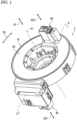
- a rotary connector device 2 includes a stator 10 and a rotator 20.
- the stator 10 is configured to be attached to a vehicle body.
- the rotator 20 is provided rotatably about a first rotational axis A1 with respect to the stator 10.
- the rotator 20 is configured to be coupled to a steering wheel.
- the rotator 20 is rotatable about the first rotational axis A1 along with the steering wheel.
- the rotary connector device 2 includes an electrical connector 30.
- the electrical connector 30 is coupled to the stator 10.
- the electrical connector 30 can also be referred to as a first electrical connector 30.
- the rotary connector device 2 includes a second electrical connector 40.
- the second electrical connector 40 is coupled to the rotator 20.
- the first electrical connector 30 is configured such that a vehicle-body-side connector is detachably connected to the first electrical connector 30.
- the first electrical connector 30 is positioned such that the vehicle-body-side connector is inserted into and detached from the first electrical connector 30 along a first direction D31.
- the vehicle-body-side connector is electrically connected to electric circuits such as a control device.
- the second electrical connector 40 is configured to such that a steering-side connector is detachably connected to the second electrical connector 40.
- the second electrical connector 40 is positioned such that the steering-side connector is inserted into and detached from the second electrical connector 40 along a second direction D32.
- the steering-side connector is electrically connected to electric circuits such as switches of a steering wheel and an airbag.
- the vehicle-body-side connector and the steering-side connector can also be referred to as an external connector.
- first direction D31 and the second direction D32 are defined parallel to the first rotational axis A1.
- at least one of the first direction D31 and the second direction D32 can be defined not to be parallel to the first rotational axis A1.
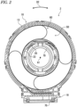
- the rotator 20 forms, along with the stator 10, a cable housing space 50 provided to surround the first rotational axis A1.
- the stator 10 and the rotator 20 forms the cable housing space 50 provided to surround the first rotational axis A1 between the stator 10 and the rotator 20.
- the cable housing space 50 has an annular shape, and extends in a circumferential direction D2 with respect to the first rotational axis A1.
- the rotary connector device 2 includes an electrical cable 60 provided in the cable housing space 50.
- the electrical connector 30 (see e.g., FIG. 1 ) is electrically connected to the electrical cable 60.
- the second electrical connector 40 (see e.g., FIG. 1 ) is electrically connected to the electrical cable 60.
- the electrical cable 60 electrically connects the first electrical connector 30 to the second electrical connector 40 (see e.g., FIG. 1 ).
- the electrical cable 60 is positioned in the cable housing space 50.
- the electrical cable 60 has flexibility and has a flat shape.
- the electrical cable 60 can also be referred to as a flexible flat cable 60.
- the rotator 20 includes an inner peripheral wall 22 and a first plate 24.
- the inner peripheral wall 22 is provided radially inward of the cable housing space 50 (see e.g., FIG. 2 ).
- the first plate 24 extends radially outward from the inner peripheral wall 22.
- the rotary connector device 2 includes a sleeve 65. The sleeve 65 is coupled to the inner peripheral wall 22 of the rotator 20.
- the stator 10 includes a first stator 11 and a second stator 12.
- the second stator 12 is a separate member from the first stator 11.
- the second stator 12 is attached to the first stator 11.
- the second stator 12 is detachably attached to the first stator 11.
- the second stator 12 is detachable from the first stator 11 and reattachable to the first stator 11.
- “detachably attached” includes a configuration which is repeatedly detachable and reattachable without substantial damage.
- the second stator 12 can be non-detachably and non-reattachably attached to the first stator 11.
- the first stator 11 includes an outer peripheral wall 13.
- the outer peripheral wall 13 is provided radially outward of the cable housing space 50 (see e.g., FIG. 2 ).
- the second stator 12 includes a second plate 14.
- the second plate 14 is attached to the outer peripheral wall 13.
- the rotary connector device 2 includes a connector coupling portion 70.
- the connector coupling portion 70 is configured to couple the electrical connector 30 to the first stator 11.
- the first stator 11 includes a connector support 18.
- the connector support 18 protrudes radially outward from the outer peripheral wall 13.
- the connector coupling portion 70 is configured to couple the electrical connector 30 to the connector support 18.
- the electrical connector 30 includes a connector case 31 and a lead block 32.
- the lead block 32 is electrically connected to the electrical cable 60.
- the lead block 32 is attached to the connector case 31.
- the connector coupling portion 70 couples the connector case 31 to the first stator 11.
- the connector coupling portion 70 couples the connector case 31 to the connector support 18.
- the second stator 12 includes a first connector cover 15.
- the first connector cover 15 extends from the second plate 14 in an axial direction D1 defined along the first rotational axis A1.
- the first connector cover 15 includes a first wall 15A, a second wall 15B, and a third wall 15C.
- the first wall 15A, the second wall 15B, and the third wall 15C extends from the second plate 14 in the axial direction D1.
- the second wall 15B and the third wall 15C extends radially outward from the first wall 15A.
- the second wall 15B is positioned to be spaced apart from the third wall 15C.
- the second plate 14 includes a second plate body 14A and an insertion portion 14B.
- the second plate body 14A extends in the circumferential direction D2.
- the insertion portion 14B extends radially outward from the second plate body 14A.
- the second wall 15B and the third wall 15C extends from the insertion portion 14B in the axial direction D1.
- the first wall 15A, the second wall 15B, the third wall 15C, and the insertion portion 14B form a connector housing space 15D.
- the electrical connector 30 is positioned in the connector housing space 15D in a state where manufacturing of the rotary connector device 2 is completed.
- the rotary connector device 2 includes a second connector cover 16.
- the second connector cover 16 is a separate member from the second stator 12 and is attached to the second stator 12.
- the second connector cover 16 is detachably attached to the first connector cover 15.
- the first connector cover 15 and the second connector cover 16 are configured to hold the electrical connector 30.
- the second plate 14 is positioned to be spaced apart from the first plate 24 in the axial direction D1.
- the insertion portion 14B is positioned to be spaced apart from the first plate 24 in the axial direction D1.
- the connector case 31 includes an internal space 31A.
- the lead block 32 is provided in the internal space 31A.
- the lead block 32 includes a first lead block 33 and a second lead block 34.
- the lead block 32 includes a lead block body and a plurality of bus bars.
- the plurality of bus bars is electrically connected to the electrical cable 60.
- the first lead block 33 includes a first lead block body 33A and a plurality of first bus bar 33B.
- the second lead block 34 includes a second lead-block body 34A and a plurality of second bus bar 34B.
- the electrical cable 60 includes a first electrical cable 61 and a second electrical cable 62.
- the first electrical cable 61 is electrically connected to the plurality of first bus bar 33B.
- the second electrical cable 62 is electrically connected to the plurality of second bus bar 34B.
- the first bus bar 33B includes a first pin terminal 33C.
- the first pin terminal 33C extends from the first lead block body 33A in the first direction D31.
- the first pin terminal 33C is contactable with a terminal of the vehicle-body-side connector.
- the second bus bar 34B includes a second pin terminal 34C.
- the second pin terminal 34C extends from the second lead-block body 34A in the first direction D31.
- the second pin terminal 34C is contactable with a terminal of the steering-side connector.
- the first pin terminal 33C extends from the first lead block body 33A in the axial direction D1.
- the second pin terminal 34C extends from the second lead-block body 34A in the axial direction D1.
- the first pin terminal 33C can extend from the first lead block body 33A in a direction different from the axial direction D1.
- the second pin terminal 34C can extend from the second lead-block body 34A in a direction different from the axial direction D1.
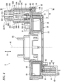
- the second electrical connector 40 includes a connector case 41 and a lead block 42.
- the lead block 42 is electrically connected to the electrical cable 60.
- the lead block 42 is attached to the connector case 41.
- the lead block 42 includes a third lead block 43 and a fourth lead block 44.
- the third lead block 43 is electrically connected to the first lead block 33 of the electrical connector 30 via the first electrical cable 61.
- the fourth lead block 44 is electrically connected to the second lead block 34 of the electrical connector 30 via the second electrical cable 62.
- the first stator 11 includes a cable guide groove 19.
- the cable guide groove 19 is in communication with the cable housing space 50 (see e.g., FIG. 7 ).
- the electrical cable 60 extends from the cable housing space 50 to the electrical connector 30 through the cable guide groove 19.
- the electrical connector 30 is positionable in a first position P1 with respect to the first stator 11 in a state where the electrical connector 30 is coupled to the first stator 11.
- the connector coupling portion 70 is at least partially provided radially outward of the electrical connector 30 with respect to the first rotational axis A1 in a state where the electrical connector 30 is positioned in the first position P1.
- the connector coupling portion 70 is partially provided radially outward of the electrical connector 30 with respect to the first rotational axis A1 in the state where the electrical connector 30 is positioned in the first position P1.
- the connector coupling portion 70 can be entirely provided radially outward of the electrical connector 30 with respect to the first rotational axis A1 in the state where the electrical connector 30 is positioned in the first position P1.
- the second stator 12 is at least partially positioned between the first stator 11 and the electrical connector 30 in the axial direction D1 defined along the first rotational axis A1 in a state where the electrical connector 30 is positioned in the first position P1 and where the second stator 12 is attached to the first stator 11.
- the second plate 14 is at least partially positioned between the first stator 11 and the electrical connector 30 in the axial direction D1 in the state where the electrical connector 30 is positioned in the first position P1 and where the second stator 12 is attached to the first stator 11.
- the second stator 12 is partially positioned between the first stator 11 and the electrical connector 30 in the axial direction D1 in the state where the electrical connector 30 is positioned in the first position P1 and where the second stator 12 is attached to the first stator 11.
- the second plate 14 is partially positioned between the first stator 11 and the electrical connector 30 in the axial direction D1 in the state where the electrical connector 30 is positioned in the first position P1 and where the second stator 12 is attached to the first stator 11.
- the second stator 12 can be entirely positioned between the first stator 11 and the electrical connector 30 in the axial direction D1 in the state where the electrical connector 30 is positioned in the first position P1 and where the second stator 12 is attached to the first stator 11.
- the second plate 14 can be entirely positioned between the first stator 11 and the electrical connector 30 in the axial direction D1 in the state where the electrical connector 30 is positioned in the first position P1 and where the second stator 12 is attached to the first stator 11.
- the second stator 12 is at least partially positioned between the first stator 11 and at least one of the connector case 31 and the lead block 32 in the axial direction D1 in the state where the electrical connector 30 is positioned in the first position P1 and where the second stator 12 is attached to the first stator 11.
- the second plate 14 is at least partially positioned between the first stator 11 and at least one of the connector case 31 and the lead block 32 in the axial direction D1 in the state where the electrical connector 30 is positioned in the first position P1 and where the second stator 12 is attached to the first stator 11.
- the second stator 12 is partially positioned between the first stator 11 and the connector case 31 and between the first stator 11 and the lead block 32 in the axial direction D1 in the state where the electrical connector 30 is positioned in the first position P1 and where the second stator 12 is attached to the first stator 11.
- the second plate 14 is partially positioned between the first stator 11 and the connector case 31 and between the first stator 11 and the lead block 32 in the axial direction D1 in the state where the electrical connector 30 is positioned in the first position P1 and where the second stator 12 is attached to the first stator 11.
- the second stator 12 can be at least partially positioned between the first stator 11 and one of the connector case 31 and the lead block 32 in the axial direction D1 in the state where the electrical connector 30 is positioned in the first position P1 and where the second stator 12 is attached to the first stator 11.
- the second plate 14 can be at least partially positioned between the first stator 11 and one of the connector case 31 and the lead block 32 in the axial direction D1 in the state where the electrical connector 30 is positioned in the first position P1 and where the second stator 12 is attached to the first stator 11.
- the electrical connector 30 includes a first surface 30A and a second surface 30B.
- the second surface 30B is provided on a reverse side of the first surface 30A.
- the second surface 30B is provided between the first rotational axis A1 and the first surface 30A in the state where the electrical connector 30 is positioned in the first position P1.
- the second surface 30B faces toward the first rotational axis A1 in the state where the electrical connector 30 is positioned in the first position P1.
- the first surface 30A is positioned in a position closer to the connector coupling portion 70 than the second surface 30B.
- the connector coupling portion 70 is configured to support the electrical connector 30 in a cantilever manner with respect to the first stator 11 such that the second surface 30B becomes a free end in the state where the electrical connector 30 is positioned in the first position P1 and where the second stator 12 is detached from the first stator 11.
- the connector coupling portion 70 is positioned in a position closer to the first surface 30A than the second surface 30B with respect to the first stator 11 to support the electrical connector 30 in a cantilever manner in the state where the electrical connector 30 is positioned in the first position P1 and where the second stator 12 is detached from the first stator 11.
- the electrical connector 30 is positioned to be spaced apart from the first stator 11 in the axial direction D1 defined along the first rotational axis A1 to form a space SP between the first stator 11 and the electrical connector 30 in a state where the electrical connector 30 is positioned in the first position P 1.
- At least one of the connector case 31 and the lead block 32 is positioned to be spaced apart from the first stator 11 in the axial direction D1 to form the space SP between the first stator 11 and the electrical connector 30 in the state where the electrical connector 30 is positioned in the first position P1.
- the connector case 31 and the lead block 32 are positioned to be spaced apart from the first stator 11 in the axial direction D1 to form the space SP between the first stator 11 and the electrical connector 30 in the state where the electrical connector 30 is positioned in the first position P1.
- only one of the connector case 31 and the lead block 32 can be positioned to be spaced apart from the first stator 11 in the axial direction D1 to form the space SP between the first stator 11 and the electrical connector 30 in the state where the electrical connector 30 is positioned in the first position P1.
- the connector coupling portion 70 is configured to couple the electrical connector 30 to the first stator 11 rotatably about a second rotational axis A2.
- the electrical connector 30 is positionable in a second position P2 different from the first position P1 with respect to the first stator 11 in a state where the electrical connector 30 is coupled to the first stator 11.
- the electrical connector 30 is rotatable between the first position P1 and the second position P2 about the second rotational axis A.
- the electrical connector 30 positioned in the first position P1 is closer to the first rotational axis A1 than the electrical connector 30 positioned in the second position P2.
- rotation of the electrical connector 30 with respect to the first stator 11 about the second rotational axis A2 can be restricted such that the electrical connector 30 is not positioned in the second position P2.
- an angle between the first position P1 and the second position P2 is approximately 90 degrees.
- the second position P2 is not limited to the illustrated position.
- a first distance DS1 between the first surface 30A and the second rotational axis A2 is shorter than a second distance DS2 between the second surface 30B and the second rotational axis A2 as viewed along the first rotational axis A1 in the state where the electrical connector 30 is positioned in the first position P1.
- the second rotational axis A2 is provided radially outward of the electrical connector 30 with respect to the first rotational axis A1 as viewed along the first rotational axis A1 in the state where the electrical connector 30 is positioned in the first position P1.
- the electrical connector 30 at least partially overlaps the first stator 11 as viewed along the first rotational axis A1 in the state where the electrical connector 30 is positioned in the first position P1.
- the electrical connector 30 entirely overlaps the first stator 11 as viewed along the first rotational axis A1 in the state where the electrical connector 30 is positioned in the first position P1.
- the electrical connector 30 can partially overlap the first stator 11 or can be positioned not to overlap the first stator 11 as viewed along the first rotational axis A1 in the state where the electrical connector 30 is positioned in the first position P1.
- the connector coupling portion 70 is configured to detachably couple the electrical connector 30 to the first stator 11.
- One of the first stator 11 and the connector coupling portion 70 includes a support hole 71.
- the other of the first stator 11 and the connector coupling portion 70 includes a pin 72 provided in the support hole 71.
- the first stator 11 includes the support hole 71.
- the connector coupling portion 70 includes the pin 72.
- the first stator 11 can include the pin 72
- the connector coupling portion 70 can include the support hole 71.
- the support hole 71 includes a first support hole 71A and a second support hole 71B.
- the pin 72 includes a first pin 72A provided in the first support hole 71A and a second pin 72B provided in the second support hole 71B.
- a total number of support holes included in the support hole 71 is not limited to a total number disclosed in the first embodiment.
- a total number of pins included in the pin 72 is not limited to a total number disclosed in the first embodiment.
- the connector coupling portion 70 includes a first coupling arm 73A and a second coupling arm 73B.
- the first coupling arm 73A and the second coupling arm 73B protrude from the electrical connector 30 in the axial direction D1.
- the first coupling arm 73A and the second coupling arm 73B protrudes from the connector case 31 in the axial direction D1.
- the first coupling arm 73A and the second coupling arm 73B protrudes from the first surface 30A in the axial direction D1.
- the first pin 72A is provided at the first coupling arm 73A.
- the second pin 72B is provided at the second coupling arm 73B.
- the first coupling arm 73A is positioned to be spaced apart from the second coupling arm 73B.
- the first pin 72A protrudes from the first coupling arm 73A away from the second pin 72B.
- the second pin 72B protrudes from the second coupling arm 73B away from the first pin 72A.
- the second stator 12 is attachable to the first stator 11 in a state where the electrical connector 30 is positioned in at least one of the first position P1 and the second position P2.
- the second plate 14 is attachable to the first stator 11 in a state where the electrical connector 30 is positioned in at least one of the first position P1 and the second position P2.
- the electrical connector 30 is rotatable between the first position P1 and the second position P2 about the second rotational axis A2 in a state where the second stator 12 is attached to the first stator 11.
- the first connector cover 15 at least partially covers the electrical connector 30 in the state where the electrical connector 30 is positioned in the first position P1.
- the first connector cover 15 and the second connector cover 16 at least partially covers the electrical connector 30 in the state where the electrical connector 30 is positioned in the first position P1.
- the first connector cover 15 partially covers the electrical connector 30 in the state where the electrical connector 30 is positioned in the first position P1.
- the first connector cover 15 and the second connector cover 16 partially covers the electrical connector 30 in the state where the electrical connector 30 is positioned in the first position P1.
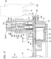
- the electrical connector 30 As shown in FIG. 11 , as viewed along the first rotational axis A1 in a state where the electrical connector 30 is positioned in the second position P2 and where the second stator 12 is attached to the first stator 11, the electrical connector 30 is positioned not to overlap the second plate 14 as viewed along the first rotational axis A1. However, the electrical connector 30 can be positioned to overlap the second plate 14 at least partially as viewed along the first rotational axis A1 in the state where the electrical connector 30 is positioned in the second position P2 and where the second stator 12 is attached to the first stator 11.
- the manufacturing method of the rotary connector device 2 will be described referring to FIG. 12 .
- the first electrical connector 30 and the second electrical connector 40 are connected to the electrical cable 60 (step S1).
- the lead block 32 (see e.g., FIG. 4 ) of the first electrical connector 30 and the lead block 42 (see e.g., FIG. 4 ) of the second electrical connector 40 are electrically connected to the electrical cable 60.
- the lead block 32 is attached to the connector case 31.
- the lead block 42 is attached to the connector case 41.
- the second electrical connector 40 is attached to the rotator 20 (step S2).
- the electrical cable 60 is wound about the rotator 20 (step S3).
- the rotator 20 is attached to the first stator 11 (step S4). Specifically, as shown in FIG. 5 , the inner peripheral wall 22 of the rotator 20 is positioned radially inward of the outer peripheral wall 13 of the first stator 11.
- the steps S3 and S4 can be executed in reverse order.
- the manufacturing method of the rotary connector device 2 includes a step of coupling the first electrical connector 30 electrically connected to the electrical cable 60 to the first stator 11 via the connector coupling portion 70.
- the connector coupling portion 70 is configured to support the first electrical connector 30 in a cantilever manner with respect to the first stator 11 such that the second surface 30B becomes a free end in a state where the first electrical connector 30 is positioned in the first position P1 and where the second stator 12 is detached from the first stator 11.
- the step of coupling the first electrical connector 30 to the first stator 11 via the connector coupling portion 70 includes a step of coupling the first electrical connector 30 to the first stator 11 via the connector coupling portion 70 in a cantilever manner such that the second surface 30B becomes a free end in the state where the first electrical connector 30 is positioned in the first position P1 and where the second stator 12 is detached from the first stator 11.
- the first electrical connector 30 is positionable in the first position P1.
- the step of coupling the first electrical connector 30 to the first stator 11 via the connector coupling portion 70 includes a step of coupling the first electrical connector 30 to the first stator 11 via the connector coupling portion 70 such that the first electrical connector 30 is positionable in the first position P1 with respect to the first stator 11.
- the pin 72 when coupling the first electrical connector 30 to the first stator 11 via the connector coupling portion 70, the pin 72 is fitted in the support hole 71. More specifically, the first pin 72A is fitted in the first support hole 71A, and the second pin 72B is fitted in the second support hole 71B.
- the step of coupling the first electrical connector 30 to the first stator 11 via the connector coupling portion 70 includes a step of coupling the first electrical connector 30 to the first stator 11 rotatably about the second rotational axis A2.
- the electrical cable 60 is attached to the first stator 11 (step S6). Specifically, as shown in FIG. 5 , the electrical cable 60 is set radially inward of the outer peripheral wall 13 of the first stator 11. Namely, the manufacturing method of the rotary connector device 2 includes a step of setting the electrical cable 60 radially inward of the outer peripheral wall 13 of the first stator 11.
- the manufacturing method of the rotary connector device 2 includes a step of attaching the second stator 12 to the first stator 11. Specifically, the first electrical connector 30 is positioned in the second position P2 in a state where the first electrical connector 30 is coupled to the first stator 11 (step S7). As shown in FIG. 9 , the second stator 12 is attached to the first stator 11 in a state where the first electrical connector 30 is positioned in the second position P2 (step S8).
- the first electrical connector 30 is positioned in the first position P1 (step S9). As shown in FIG. 9 , the first electrical connector 30 is rotated from the second position P2 to the first position P1 about the second rotational axis A2 in a state where the second stator 12 is attached to the first stator 11. At this time, the first electrical connector 30 is inserted into the connector housing space 15D of the first connector cover 15. The second stator 12 is at least partially positioned between the first stator 11 and the first electrical connector 30 in the axial direction D1 in the state where the first electrical connector 30 is positioned in the first position P1.
- the step of attaching the second stator 12 to the first stator 11 includes a step of attaching the second stator 12 to the first stator 11 such that the second stator 12 is at least partially positioned between the first stator 11 and the first electrical connector 30 in the axial direction D1 defined along the first rotational axis A1.
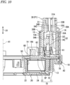
- the second connector cover 16 is attached to the first stator 11 (step S10). As shown in FIG. 10 , the second connector cover 16 is attached to the first connector cover 15 in the state where the first electrical connector 30 is positioned in the first position P1. Thus, the position of the first electrical connector 30 is stabilized in the first position P1.
- the second stator 12 is attached to the first stator 11 in a state where the first electrical connector 30 is positioned in the second position P2.
- the second stator 12 can be attached to the first stator 11 in the state where the first electrical connector 30 is positioned in the first position P1.
- the step S7 the first electrical connector 30 is positioned in the first position P1
- the step S9 is omitted.
- a rotary connector device 202 in accordance with a second embodiment will be described below referring to FIGS. 13 to 18 .
- the rotary connector device 202 has the same structure as those of the rotary connector device 2 except for the electrical connector 30.
- elements having substantially the same function as those in the first embodiment will be numbered the same here and will not be described and/or illustrated again in detail here for the sake of brevity.
- the rotary connector device 202 includes the stator 10, the rotator 20, the electrical cable 60, the electrical connector 30, and connector coupling portion 270.
- the stator 10 has the same structure as the structure of the stator 10 of the first embodiment.
- the rotator 20 has the same structure as the structure of the rotator 20 of the first embodiment.
- the electrical connector 30 has the same structure as the structure of the electrical connector 30 of the first embodiment.
- the connector coupling portion 270 has the same structure as the structure of the connector coupling portion 70 of the first embodiment.
- the stator 10 includes a first stator 211 and the second stator 12.
- the first stator 211 includes the outer peripheral wall 13 and a connector support 218.
- the connector support 218 protrudes radially outward from the outer peripheral wall 13.
- the connector coupling portion 270 is configured to couple the electrical connector 30 to the first stator 211.
- the connector coupling portion 270 is configured to couple the electrical connector 30 to the connector support 218.
- the connector coupling portion 270 couples the connector case 31 to the first stator 211.
- the connector coupling portion 270 couples the connector case 31 to the connector support 218.
- the connector coupling portion 270 is at least partially provided radially outward of the electrical connector 30 with respect to the first rotational axis A1 in the state where the electrical connector 30 is positioned in the first position P1.
- the connector coupling portion 270 is partially provided radially outward of the electrical connector 30 with respect to the first rotational axis A1 in the state where the electrical connector 30 is positioned in the first position P1.
- the connector coupling portion 270 can be provided radially outward of the electrical connector 30 with respect to the first rotational axis A1 in the state where the electrical connector 30 is positioned in the first position P1.
- the connector coupling portion 270 is configured to support the electrical connector 30 in a cantilever manner with respect to the first stator 211 such that the second surface 30B becomes a free end in the state where the electrical connector 30 is positioned in the first position P1 and where the second stator 12 is detached from the first stator 211.
- the connector coupling portion 270 is positioned in a position closer to the first surface 30A than the second surface 30B to support the electrical connector 30 in a cantilever with respect to the first stator 211 in the state where the electrical connector 30 is positioned in the first position P1 and where the second stator 12 is detached from the first stator 211.
- the connector coupling portion 270 is configured to couple the electrical connector 30 to the first stator 211 to hold the electrical connector 30 in the first position P1.
- the connector coupling portion 270 restricts rotation of the electrical connector 30 with respect to the first stator 211 about the second rotational axis A2 such that the electrical connector 30 is not positioned in the second position P2.
- the connector coupling portion 270 is configured to detachably couple the electrical connector 30 to the first stator 211.
- the connector coupling portion 270 fastens the connector case 31 to the first stator 211.
- the connector coupling portion 270 includes a first connector coupling portion 271 and a second connector coupling portion 272.
- the first connector coupling portion 271 is positioned to be spaced apart from the second connector coupling portion 272.
- the first connector coupling portion 271 includes a first coupling portion 271A and a first pin 271B.
- the first coupling portion 271A protrudes from the connector case 31 in the axial direction D1.
- the first pin 271B protrudes from the first coupling portion 271Ain a direction different from the axial direction D1.
- the second connector coupling portion 272 includes a second coupling portion 272A and a second pin 272B.
- the second coupling portion 272A protrudes from the connector case 31 in the axial direction D1.
- the second pin 272B protrudes from the second coupling portion 272A in the axial direction D1.
- the connector support 218 includes a coupling groove 219.
- the connector coupling portion 270 is at least partially positioned in the coupling groove 219 in a state where the electrical connector 30 is coupled to the first stator 211.
- the coupling groove 219 includes a first groove 219A, a second groove 219B, a third groove 219C.
- the first pin 271B is at least partially positioned in the first groove 219A in the state where the electrical connector 30 is coupled to the first stator 211.
- the second pin 272B is at least partially positioned in the second groove 219B in the state where the electrical connector 30 is coupled to the first stator 211.
- the first coupling portion 271A is at least partially positioned in the third groove 219C in the state where the electrical connector 30 is coupled to the first stator 211.
- the second coupling portion 272A is at least partially positioned in the third groove 219C in the state where the electrical connector 30 is coupled to the first stator 211.
- the third groove 219C includes a first inner surface 219D, a second inner surface 219E, and a bottom surface 219F.
- the connector coupling portion 270 is in contact with the bottom surface 219F in the state where the electrical connector 30 is positioned in the first position P1.
- the connector coupling portion 270 is at least partially positioned between the first inner surface 219D and the second inner surface 219E in the state where the electrical connector 30 is positioned in the first position P1.
- the connector coupling portion 270 is contactable with the first inner surface 219D and the second inner surface 219E.
- the third groove 219C restricts rotation of the connector coupling portion 270.
- the second stator 12 is attachable to the first stator 211 in a state where the electrical connector 30 is detached from the first stator 211 (a state where the connector coupling portion 270 does not couple the electrical connector 30 to the first stator 211).
- the second plate 14 is attachable to the first stator 211 in the state where the electrical connector 30 is detached from the first stator 211 (the state where the connector coupling portion 270 does not couple the electrical connector 30 to the first stator 211).
- the second stator 12 is attachable to the first stator 211 in the state where the electrical connector 30 is positioned in the first position P1.
- the second plate 14 is attachable to the first stator 211 in the state where the electrical connector 30 is positioned in the first position P1.
- the second stator 12 may not be attachable to the first stator 211 in the state where the electrical connector 30 is positioned in the first position P1.
- the second plate 14 may not be attachable to the first stator 211 in the state where the electrical connector 30 is positioned in the first position P1.
- the manufacturing method of the rotary connector device 202 will be described referring to FIG. 18 .
- the steps S5, S7, and S9 shown in FIG. 12 are replaced with the steps S25, S27, and S29.
- the first electrical connector 30 is temporarily positioned at the first stator 211 (step S25). Specifically, the first electrical connector 30 is coupled to the first stator 211 via the connector coupling portion 270. Namely, the manufacturing method of the rotary connector device 202 includes a step of coupling the first electrical connector 30 electrically connected to the electrical cable 60 to the first stator 211 via the connector coupling portion 270.
- the connector coupling portion 270 is configured to support the first electrical connector 30 in a cantilever manner with respect to the first stator 211 such that the second surface 30B becomes a free end in the state where the first electrical connector 30 is positioned in the first position P1 and where the second stator 12 is detached from the first stator 211.
- the step of coupling the first electrical connector 30 to the first stator 211 via the connector coupling portion 270 includes a step of coupling the first electrical connector 30 to the first stator 211 via the connector coupling portion 270 in a cantilever manner such that the second surface 30B becomes a free end in the state where the first electrical connector 30 is positioned in the first position P1 and where the second stator 12 is detached from the first stator 211.
- the first electrical connector 30 is positionable in the first position P1.
- the step of coupling the first electrical connector 30 to the first stator 211 via the connector coupling portion 270 includes a step of coupling the first electrical connector 30 to the first stator 211 via the connector coupling portion 270 such that the first electrical connector 30 is positionable in the first position P1 with respect to the first stator 211.
- the electrical cable 60 is attached to the first stator 211 (step S5). Specifically, as shown in FIG. 14 , the electrical cable 60 is set radially inward of the outer peripheral wall 13 of the first stator 211. Namely, the manufacturing method of the rotary connector device 202 includes a step of setting the electrical cable 60 radially inward of the outer peripheral wall 13 of the first stator 211. After the electrical cable 60 is attached to the first stator 211, the first electrical connector 30 is detached from the first stator 211 (step S27).
- the manufacturing method of the rotary connector device 202 includes a step of attaching the second stator 12 to the first stator 211. Specifically, as shown in FIG. 17 , the second stator 12 is attached to the first stator 211 in a state where the first electrical connector 30 is detached from the first stator 211 (step S8).
- the second stator 12 is at least partially positioned between the first stator 211 and the first electrical connector 30 in the axial direction D1 in the state where the first electrical connector 30 is positioned in the first position P1.
- the step of attaching the second stator 12 to the first stator 211 includes a step of attaching the second stator 12 to the first stator 211 such that the second stator 12 is at least partially positioned between the first stator 211 and the first electrical connector 30 in the axial direction D1 defined along the first rotational axis A1.
- the first electrical connector 30 is coupled to the first stator 211 again (step S29).
- the second stator 12 is attached to the first stator 211 in the state where the first electrical connector 30 is detached from the first stator 211.
- the second stator 12 can be attached to the first stator 211 in the state where the first electrical connector 30 is positioned in the first position P1.
- the rotary connector device 2 or 202 includes the stator 10, the rotator 20, the electrical cable 60, the electrical connector 30, and the connector coupling portion 70 or 270.
- the stator 10 includes the first stator 11 or 211 and the second stator 12 attached to the first stator 11 or 211.
- the rotator 20 is provided rotatably about the first rotational axis A1 with respect to the stator 10 and forms, along with the stator 10, the cable housing space 50 provided to surround the first rotational axis A1.
- the electrical cable 60 is provided in the cable housing space 50.
- the electrical connector 30 is electrically connected to the electrical cable 60.
- the connector coupling portion 70 or 270 is configured to couple the electrical connector 30 to the first stator 11 or 211.
- the electrical connector 30 is positionable in the first position P1 with respect to the first stator 11 or 211 in a state where the electrical connector 30 is coupled to the first stator 11 or 211.
- the electrical connector 30 includes the first surface 30A and the second surface 30B provided on a reverse side of the first surface 30A.
- the second surface 30B is positioned between the first rotational axis A1 and the first surface 30A in the state where the electrical connector 30 is positioned in the first position P1.
- the connector coupling portion 70 or 270 is configured to support the electrical connector 30 in a cantilever manner with respect to the first stator 11 or 211 such that the second surface 30B become a free end in the state where the electrical connector 30 is positioned in the first position P1 and where the second stator 12 is detached from the first stator 11 or 211.
- the second stator 12 is at least partially positioned between the first stator 11 or 211 and the electrical connector 30 in the axial direction D1 defined along the first rotational axis A1 in the state where the electrical connector 30 is positioned in the first position P1 and where the second stator 12 is attached to the first stator 11 or 211.
- the connector coupling portion 70 or 270 is configured to support the electrical connector 30 in a cantilever manner with respect to the first stator 11 or 211 such that the second surface 30B becomes a free end in the state where the electrical connector 30 is positioned in the first position P1 and where the second stator 12 is detached from the first stator 11 or 211.
- the position of the electrical connector 30 can be close to the first rotational axis A1 while making it easier to attach the second stator 12 to the first stator 11 or 211.
- This can provide the rotary connector device 2 or 202 that enables compatibility between improvement of assembling and downsizing.
- the manufacturing method of the rotary connector device 2 or 202 includes a step of setting the electrical cable 60 radially inward of the outer peripheral wall of the first stator 11 or 211, a step of coupling the electrical connector 30 electrically connected to the electrical cable 60 to the first stator 11 or 211 via the connector coupling portion 70 or 270, and a step of attaching the second stator to the first stator 11 or 211.
- the step of coupling the electrical connector 30 to the first stator 11 or 211 via the connector coupling portion 70 or 270 includes the step of coupling the electrical connector 30 to the first stator 11 or 211 via the connector coupling portion 70 or 270 such that the electrical connector 30 is positionable in the first position P1 with respect to the first stator 11 or 211.
- the electrical connector 30 includes the first surface 30A and the second surface 30B provided on a reverse side of the first surface 30A.
- the second surface 30B is positioned between the first rotational axis and the first surface 30A in a state where the electrical connector 30 is positioned in the first position P1.
- the step of coupling the electrical connector 30 to the first stator 11 or 211 via the connector coupling portion 70 or 270 includes the step of coupling the electrical connector 30 to the first stator 11 or 211 in a cantilever manner via the connector coupling portion 70 or 270 such that the second surface 30B becomes a free end in the state where the electrical connector 30 is positioned in the first position P1 and where the second stator is detached from the first stator 11 or 211.
- the step of attaching the second stator to the first stator 11 or 211 includes the step of attaching the second stator to the first stator 11 or 211 such that the second stator is at least partially positioned between the first stator 11 or 211 and the electrical connector 30 in the axial direction defined along the first rotational axis.
- the step of coupling the electrical connector 30 to the first stator 11 or 211 via the connector coupling portion 70 or 270 includes the step of coupling the electrical connector 30 to the first stator 11 or 211 in a cantilever manner via the connector coupling portion 70 or 270 such that the second surface 30B becomes a free end in the state where the electrical connector 30 is positioned in the first position P1 and where the second stator is detached from the first stator 11 or 211.
- the position of the electrical connector 30 can be close to the first rotational axis A1 while making it easier to attach the second stator 12 to the first stator 11 or 211.
- This can provide the manufacturing method of the rotary connector device 2 or 202 that enables compatibility between improvement of assembling and downsizing.
- first and second recited in the present application are merely identifiers, but do not have any other meanings (for example, a particular order and the like). Moreover, for example, the term “first element” itself does not imply an existence of “second element,” and the term “second element” itself does not imply an existence of "first element.”
- the expression "at least one of A and B” in the present disclosure includes, for example, all of (1) A alone, (2) B alone, and (3) both A and B.
- the expression "at least one of A, B and C” includes, for example, all of (1) A alone, (2) B alone, (3) C alone, (4) A and B, (5) B and C, (6) A and C, and (7) A, B and C.
- the expression "at least one of A and B” is not construed as "at least one of A and at least one of B.”
Landscapes
- Engineering & Computer Science (AREA)
- Manufacturing & Machinery (AREA)
- Mechanical Engineering (AREA)
- Motor Or Generator Frames (AREA)
Abstract
Description
- The technology disclosed in the present application relates to a rotary connector device and a manufacturing method of a rotary connector device.
- A manufacturing method of a rotary connector device is described in the
Patent Document 1. - Patent Document 1:
WO 2020/075559 - With an assembly method described in the
Patent Document 1, a rotator about which a flexible flat cable is wound is assembled to a sub stator, and a connector is temporarily fixed to the sub stator. In that state, a stator body is assembled to the sub stator, and the connector is assembled to the stator body. - However, it is preferable to further improve the assembling method described in the
Patent Document 1 and to enable compatibility with downsizing. - An object of the technology disclosed in the present application is to provide a rotary connector device and a manufacturing method of a rotary connector device that enable compatibility between improvement of assembling and downsizing.
- In accordance with a first aspect, a rotary connector device includes, a stator, a rotator, an electrical cable, an electrical connector, and a connector coupling portion. The stator includes a first stator and a second stator attached to the first stator. The rotator is provided rotatably about a first rotational axis with respect to the stators and forms, along with the stator, a cable housing space provided to surround the first rotational axis. The electrical cable is provided in the cable housing space. The electrical connector is electrically connected to the electrical cable. The connector coupling portion is configured to couple the electrical connector to the first stator. The electrical connector is positionable in a first position with respect to the first stator in a state where the electrical connector is coupled to the first stator. The electrical connector includes a first surface and a second surface provided on a reverse side of the first surface. The second surface is positioned between the first rotational axis and the first surface in a state where the electrical connector is positioned in the first position. The connector coupling portion is configured to support the electrical connector in a cantilever manner with respect to the first stator such that the second surface becomes a free end in a state where the electrical connector is positioned in the first position and where the second stator is detached from the first stator. The second stator is at least partially positioned between the first stator and the electrical connector in an axial direction defined along the first rotational axis in a state where the electrical connector is positioned in the first position and where the second stator is attached to the first stator.
- With the rotary connector device according to the first aspect, the connector coupling portion is configured to support the electrical connector in a cantilever manner with respect to the first stator such that the second surface becomes a free end in the state where the electrical connector is positioned in the first position and where the second stator is detached from the first stator. Thus, the position of the electrical connector can be close to the first rotational axis while making it easier to attach the second stator to the first stator. This can provide the rotary connector device that enables compatibility between improvement of assembling and downsizing.
- In accordance with a second aspect, in the rotary connector device according to the first aspect, the rotator includes an inner peripheral wall provided radially inward of the cable housing space and a first plate extending radially outward from the inner peripheral wall. The first stator includes an outer peripheral wall provided radially outward of the cable housing space. The second stator includes a second plate attached to the outer peripheral wall and spaced apart from the first plate in the axial direction. The second plate is at least partially positioned between the first stator and the electrical connector in the axial direction in a state where the electrical connector is positioned in the first position and where the second stator is attached to the first stator.
- With the rotary connector device according to the second aspect, it is possible to improve assembling by positioning the second plate at least partially between the first stator and the electrical connector in the axial direction.
- In accordance with a third aspect, in the rotary connector device according to the first or second aspect, the connector coupling portion is configured to couple the electrical connector to the first stator rotatably about a second rotational axis.
- With the rotary connector device according to the third aspect, it is possible to improve flexibility of the position of the electrical connector with respect to the first stator while stabilizing the position of the electrical connector with respect to the first stator.
- In accordance with a fourth aspect, in the rotary connector device according to the third aspect, a first distance between the first surface and the second rotational axis is shorter than a second distance between the second surface and the second rotational axis as viewed along the first rotational axis in a state where the electrical connector is positioned in the first position.
- With the rotary connector device according to the fourth aspect, it becomes easy to arrange the electrical connector radially inward, making it easy to downsize the rotary connector device.
- In accordance with a fifth aspect, in the rotary connector device according to the third or fourth aspect, the second rotational axis is provided radially outward of the electrical connector with respect to the first rotational axis as viewed along the first rotational axis in a state where the electrical connector is positioned in the first position.
- With the rotary connector device according to the fifth aspect, it becomes easy to arrange the electrical connector radially inward, making it easier to downsize the rotary connector device.
- In accordance with a sixth aspect, in the rotary connector device according to any one of the third to fifth aspect, the electrical connector is rotatable about the second rotational axis between the first position and the second position. The electrical connector positioned in the first position is closer to the first rotational axis than the electrical connector positioned in the second position.
- With the rotary connector device according to the sixth aspect, it becomes easy to attach the second stator to the first stator by arranging the electrical connector in the second position when attaching the second stator to the first stator.
- In accordance with a seventh aspect, in the rotary connector device according to the sixth aspect, the electrical connector is positioned not to overlap with the second plate as viewed along the first rotational axis in a state where the electrical connector is positioned in the second position and where the second stator is attached to the first stator.
- With the rotary connector device according to the seventh aspect, it becomes easier to attach the second stator to the first stator by arranging the electrical connector in the second position when attaching the second stator to the first stator.
- In accordance with an eighth aspect, in the rotary connector device according to the sixth or seventh aspect, the electrical connector is rotatable about the second rotational axis between the first position and the second position in a state where the second stator is attached to the first stator.
- With the rotary connector device according to the eighth aspect, it is possible to arrange the electrical connector in the first position after attaching the second stator to the first stator, making it easier to attach the second stator to the first stator.
- In accordance with the ninth aspect, in the rotary connector device according to any one of the third to eighth aspect, the electrical connector includes a connector case including an internal space and a lead block electrically connected to the electrical cable provided in the internal space. The second stator is at least partially positioned between the first stator and at least one of the connector case and the lead block in the axial direction in a state where the electrical connector is positioned in the first position and where the second stator is attached to the first stator.
- With the rotary connector device according to the ninth aspect, it becomes easy to arrange the electrical connector radially inward, making it easy to downsize the rotary connector device.
- In accordance with the tenth aspect, in the rotary connector device according to the ninth aspect, the second rotational axis is provided radially outward of the lead block with respect to the first rotational axis as viewed along the first rotational axis in the state where the electrical connector is positioned in the first position.
- With the rotary connector device according to the tenth aspect, it becomes easier to arrange the electrical connector radially inward, making it easier to downsize the rotary connector device.
- In accordance with the eleventh aspect, in the rotary connector device according to any one of the first to tenth aspects, one of the first stator and the connector coupling portion includes a supporting hole. The other of the first stator and the connector coupling portion includes a pin provided in the supporting hole.
- With the rotary connector device according to the eleventh aspect, it is possible to realize the connector coupling portion with a simple structure.
- In accordance with the twelfth aspect, in the rotary connector device according to the eleventh aspect, the supporting hole includes a first supporting hole and a second supporting hole. The pin includes a first pin provided in the first supporting hole and a second pin provided in the second supporting hole.
- With the rotary connector device according to the twelfth aspect, the coupling strength between the first stator and the electrical connector by the connector coupling portion improves.
- In accordance with the thirteenth aspect, in the rotary connector device according to any one of the first to twelfth aspects, the connector coupling portion is configured to detachably couple the electrical connector to the first stator.
- With the rotary connector device according to the thirteenth aspect, it becomes easy to attach the second stator to the first stator by detaching the electrical connector when attaching the second stator to the first stator.
- In accordance with the fourteenth aspect, a manufacturing method of a rotary connector device includes steps of: setting an electrical cable radially inward of an outer peripheral wall of a first stator; coupling an electrical connector connected electrically to the electrical cable to the first stator via a connector coupling portion; attaching a second stator to the first stator. The step of coupling the electrical connector to the first stator via the connector coupling portion includes a step of coupling the electrical connector to the first stator via the connector coupling portion so that the electrical connector is positionable in a first position with respect to the first stator. The electrical connector includes a first surface and a second surface provided on a reverse side of the first surface. The second surface is positioned between a first rotational axis and the first surface in a state where the electrical connector is positioned in the first position. The step of coupling the electrical connector to the first stator via the connector coupling portion includes a step of coupling the electrical connector to the first stator in a cantilever manner via the connector coupling portion so that the second surface becomes a free end in a state where the electrical connector is positioned in the first position and where the second stator is detached from the first stator. The step of attaching the second stator to the first stator includes a step of attaching the second stator to the first stator so that the second stator is at least partially positioned between the first stator and the electrical connector in an axial direction defined along the first rotational axis.
- With the manufacturing method according to the fourteenth aspect, the step of coupling the electrical connector to the first stator via the connector coupling portion includes the step of coupling the electrical connector to the first stator in a cantilever manner via the connector coupling portion so that the second surface becomes a free end in a state where the electrical connector is positioned in the first position and where the second stator is detached from the first stator. Thus, the position of the electrical connector can be close to the first rotational axis while making it easier to attach the second stator to the first stator. This can provide the rotary connector device that enables compatibility between improvement of assembling and downsizing.
- In accordance with the fifteenth aspect, in the manufacturing method according to the fourteenth aspect, the step of coupling the electrical connector to the first stator via the connector coupling portion includes a step of coupling the electrical connector to the first stator rotatably about the second rotational axis.
- With the manufacturing method according to the fifteenth aspect, it is possible to improve flexibility of the position of the electrical connector with respect to the first stator while stabilizing the position of the electrical connector with respect to the first stator.
- With the technology disclosed in the present application, it is possible to provide a rotary connector device and a manufacturing method of a rotary connector device that enable compatibility between improvement of assembling and downsizing.
-
-
FIG. 1 is a perspective view of a rotary connector device in accordance with a first embodiment. -
FIG. 2 is a cross-sectional view of the rotary connector device taken along line II-II ofFIG. 1 . -
FIG. 3 is an exploded perspective view of a rotary connector device shown inFIG. 1 . -
FIG. 4 is a cross-sectional view of a rotary connector device taken along line IV-IV ofFIG. 8 . -
FIG. 5 is a cross-sectional view of a first stator, a rotator, an electrical cable, an electrical connector, and a connector coupling portion of the rotary connector device shown inFIG. 1 . -
FIG. 6 is a plan view of the first stator, the electrical connector, and the connector coupling portion of the rotary connector device shown inFIG. 1 . -
FIG. 7 is an exploded perspective view of the first stator, the electrical connector, and the connector coupling portion of the rotary connector device shown inFIG. 1 . -
FIG. 8 is a cross-sectional view of the rotary connector device taken along line VIII-VIII ofFIG. 4 . -
FIG. 9 is a cross-sectional view of the first stator, the second stator, the rotator, the electrical cable, the electrical connector, and the connector coupling portion of the rotary connector device shown inFIG. 1 . -
FIG. 10 is a cross-sectional view of the rotary connector device taken along line X-X ofFIG. 8 . -
FIG. 11 is a plan view of the first stator and the second stator of the rotary connector device shown inFIG. 1 . -
FIG. 12 shows a flowchart of a manufacturing method of the rotary connector device shown inFIG. 1 . -
FIG. 13 is a cross-sectional view of a rotary connector device in accordance with a second embodiment. -
FIG. 14 is a cross-sectional view of a first stator, a rotator, electrical cable, an electrical connector, and a connector coupling portion of the rotary connector device shown inFIG. 13 . -
FIG. 15 is a perspective view of the first stator, the electrical connector, and the connector coupling portion of the rotary connector device shown inFIG. 13 . -
FIG. 16 is an exploded perspective view of the first stator, the electrical connector, and the connector coupling portion of the rotary connector device shown inFIG. 13 . -
FIG. 17 is a cross-sectional view of the first stator, the second stator, the rotator, the electrical cable, the electrical connector, and the connector coupling portion of the rotary connector device shown inFIG. 13 . -
FIG. 18 shows a flowchart of a manufacturing method of the rotary connector device shown inFIG. 13 . - Embodiments will be described below with reference to the drawings. In the drawings, the same reference signs indicate corresponding or identical configurations.
- As shown in
FIG. 1 , arotary connector device 2 includes astator 10 and arotator 20. Thestator 10 is configured to be attached to a vehicle body. Therotator 20 is provided rotatably about a first rotational axis A1 with respect to thestator 10. Therotator 20 is configured to be coupled to a steering wheel. Therotator 20 is rotatable about the first rotational axis A1 along with the steering wheel. - The
rotary connector device 2 includes anelectrical connector 30. Theelectrical connector 30 is coupled to thestator 10. Theelectrical connector 30 can also be referred to as a firstelectrical connector 30. Therotary connector device 2 includes a secondelectrical connector 40. The secondelectrical connector 40 is coupled to therotator 20. The firstelectrical connector 30 is configured such that a vehicle-body-side connector is detachably connected to the firstelectrical connector 30. The firstelectrical connector 30 is positioned such that the vehicle-body-side connector is inserted into and detached from the firstelectrical connector 30 along a first direction D31. The vehicle-body-side connector is electrically connected to electric circuits such as a control device. The secondelectrical connector 40 is configured to such that a steering-side connector is detachably connected to the secondelectrical connector 40. The secondelectrical connector 40 is positioned such that the steering-side connector is inserted into and detached from the secondelectrical connector 40 along a second direction D32. The steering-side connector is electrically connected to electric circuits such as switches of a steering wheel and an airbag. The vehicle-body-side connector and the steering-side connector can also be referred to as an external connector. - In the present embodiment, the first direction D31 and the second direction D32 are defined parallel to the first rotational axis A1. However, at least one of the first direction D31 and the second direction D32 can be defined not to be parallel to the first rotational axis A1.
- As shown in
FIG. 2 , therotator 20 forms, along with thestator 10, acable housing space 50 provided to surround the first rotational axis A1. Thestator 10 and therotator 20 forms thecable housing space 50 provided to surround the first rotational axis A1 between thestator 10 and therotator 20. For example, thecable housing space 50 has an annular shape, and extends in a circumferential direction D2 with respect to the first rotational axis A1. - The
rotary connector device 2 includes anelectrical cable 60 provided in thecable housing space 50. The electrical connector 30 (see e.g.,FIG. 1 ) is electrically connected to theelectrical cable 60. The second electrical connector 40 (see e.g.,FIG. 1 ) is electrically connected to theelectrical cable 60. Namely, theelectrical cable 60 electrically connects the firstelectrical connector 30 to the second electrical connector 40 (see e.g.,FIG. 1 ). Theelectrical cable 60 is positioned in thecable housing space 50. Theelectrical cable 60 has flexibility and has a flat shape. Theelectrical cable 60 can also be referred to as a flexibleflat cable 60. - As shown in
FIG. 3 , therotator 20 includes an innerperipheral wall 22 and afirst plate 24. The innerperipheral wall 22 is provided radially inward of the cable housing space 50 (see e.g.,FIG. 2 ). Thefirst plate 24 extends radially outward from the innerperipheral wall 22. Therotary connector device 2 includes asleeve 65. Thesleeve 65 is coupled to the innerperipheral wall 22 of therotator 20. - The
stator 10 includes afirst stator 11 and asecond stator 12. Thesecond stator 12 is a separate member from thefirst stator 11. Thesecond stator 12 is attached to thefirst stator 11. In the first embodiment, thesecond stator 12 is detachably attached to thefirst stator 11. Thesecond stator 12 is detachable from thefirst stator 11 and reattachable to thefirst stator 11. Here, "detachably attached" includes a configuration which is repeatedly detachable and reattachable without substantial damage. However, thesecond stator 12 can be non-detachably and non-reattachably attached to thefirst stator 11. - The
first stator 11 includes an outerperipheral wall 13. The outerperipheral wall 13 is provided radially outward of the cable housing space 50 (see e.g.,FIG. 2 ). The second stator 12includes asecond plate 14. Thesecond plate 14 is attached to the outerperipheral wall 13. - The
rotary connector device 2 includes aconnector coupling portion 70. Theconnector coupling portion 70 is configured to couple theelectrical connector 30 to thefirst stator 11. Thefirst stator 11 includes aconnector support 18. Theconnector support 18 protrudes radially outward from the outerperipheral wall 13. Theconnector coupling portion 70 is configured to couple theelectrical connector 30 to theconnector support 18. - The
electrical connector 30 includes aconnector case 31 and alead block 32. Thelead block 32 is electrically connected to theelectrical cable 60. Thelead block 32 is attached to theconnector case 31. Theconnector coupling portion 70 couples theconnector case 31 to thefirst stator 11. Theconnector coupling portion 70 couples theconnector case 31 to theconnector support 18. - The
second stator 12 includes afirst connector cover 15. Thefirst connector cover 15 extends from thesecond plate 14 in an axial direction D1 defined along the first rotational axis A1. Thefirst connector cover 15 includes afirst wall 15A, asecond wall 15B, and athird wall 15C. Thefirst wall 15A, thesecond wall 15B, and thethird wall 15C extends from thesecond plate 14 in the axial direction D1. Thesecond wall 15B and thethird wall 15C extends radially outward from thefirst wall 15A. Thesecond wall 15B is positioned to be spaced apart from thethird wall 15C. - The
second plate 14 includes asecond plate body 14A and aninsertion portion 14B. Thesecond plate body 14A extends in the circumferential direction D2. Theinsertion portion 14B extends radially outward from thesecond plate body 14A. Thesecond wall 15B and thethird wall 15C extends from theinsertion portion 14B in the axial direction D1. Thefirst wall 15A, thesecond wall 15B, thethird wall 15C, and theinsertion portion 14B form aconnector housing space 15D. Theelectrical connector 30 is positioned in theconnector housing space 15D in a state where manufacturing of therotary connector device 2 is completed. - The
rotary connector device 2 includes asecond connector cover 16. Thesecond connector cover 16 is a separate member from thesecond stator 12 and is attached to thesecond stator 12. Thesecond connector cover 16 is detachably attached to thefirst connector cover 15. Thefirst connector cover 15 and thesecond connector cover 16 are configured to hold theelectrical connector 30. - As shown in
FIG. 4 , thesecond plate 14 is positioned to be spaced apart from thefirst plate 24 in the axial direction D1. Theinsertion portion 14B is positioned to be spaced apart from thefirst plate 24 in the axial direction D1. - The
connector case 31 includes aninternal space 31A. Thelead block 32 is provided in theinternal space 31A. In the first embodiment, thelead block 32 includes afirst lead block 33 and asecond lead block 34. - The
lead block 32 includes a lead block body and a plurality of bus bars. The plurality of bus bars is electrically connected to theelectrical cable 60. In the first embodiment, thefirst lead block 33 includes a firstlead block body 33A and a plurality offirst bus bar 33B. Thesecond lead block 34 includes a second lead-block body 34A and a plurality ofsecond bus bar 34B. Theelectrical cable 60 includes a firstelectrical cable 61 and a secondelectrical cable 62. The firstelectrical cable 61 is electrically connected to the plurality offirst bus bar 33B. The secondelectrical cable 62 is electrically connected to the plurality ofsecond bus bar 34B. - The
first bus bar 33B includes afirst pin terminal 33C. Thefirst pin terminal 33C extends from the firstlead block body 33A in the first direction D31. Thefirst pin terminal 33C is contactable with a terminal of the vehicle-body-side connector. - The
second bus bar 34B includes asecond pin terminal 34C. Thesecond pin terminal 34C extends from the second lead-block body 34A in the first direction D31. Thesecond pin terminal 34C is contactable with a terminal of the steering-side connector. - In the first embodiment, the
first pin terminal 33C extends from the firstlead block body 33A in the axial direction D1. Thesecond pin terminal 34C extends from the second lead-block body 34A in the axial direction D1. However, thefirst pin terminal 33C can extend from the firstlead block body 33A in a direction different from the axial direction D1. Thesecond pin terminal 34C can extend from the second lead-block body 34A in a direction different from the axial direction D1. - The second
electrical connector 40 includes aconnector case 41 and alead block 42. Thelead block 42 is electrically connected to theelectrical cable 60. Thelead block 42 is attached to theconnector case 41. Thelead block 42 includes athird lead block 43 and afourth lead block 44. Thethird lead block 43 is electrically connected to thefirst lead block 33 of theelectrical connector 30 via the firstelectrical cable 61. Thefourth lead block 44 is electrically connected to thesecond lead block 34 of theelectrical connector 30 via the secondelectrical cable 62. - The
first stator 11 includes acable guide groove 19. Thecable guide groove 19 is in communication with the cable housing space 50 (see e.g.,FIG. 7 ). Theelectrical cable 60 extends from thecable housing space 50 to theelectrical connector 30 through thecable guide groove 19. - As shown in
FIG. 4 , theelectrical connector 30 is positionable in a first position P1 with respect to thefirst stator 11 in a state where theelectrical connector 30 is coupled to thefirst stator 11. Theconnector coupling portion 70 is at least partially provided radially outward of theelectrical connector 30 with respect to the first rotational axis A1 in a state where theelectrical connector 30 is positioned in the first position P1. In the first embodiment, theconnector coupling portion 70 is partially provided radially outward of theelectrical connector 30 with respect to the first rotational axis A1 in the state where theelectrical connector 30 is positioned in the first position P1. However, theconnector coupling portion 70 can be entirely provided radially outward of theelectrical connector 30 with respect to the first rotational axis A1 in the state where theelectrical connector 30 is positioned in the first position P1. - The
second stator 12 is at least partially positioned between thefirst stator 11 and theelectrical connector 30 in the axial direction D1 defined along the first rotational axis A1 in a state where theelectrical connector 30 is positioned in the first position P1 and where thesecond stator 12 is attached to thefirst stator 11. Thesecond plate 14 is at least partially positioned between thefirst stator 11 and theelectrical connector 30 in the axial direction D1 in the state where theelectrical connector 30 is positioned in the first position P1 and where thesecond stator 12 is attached to thefirst stator 11. - In the first embodiment, the
second stator 12 is partially positioned between thefirst stator 11 and theelectrical connector 30 in the axial direction D1 in the state where theelectrical connector 30 is positioned in the first position P1 and where thesecond stator 12 is attached to thefirst stator 11. Thesecond plate 14 is partially positioned between thefirst stator 11 and theelectrical connector 30 in the axial direction D1 in the state where theelectrical connector 30 is positioned in the first position P1 and where thesecond stator 12 is attached to thefirst stator 11. However, thesecond stator 12 can be entirely positioned between thefirst stator 11 and theelectrical connector 30 in the axial direction D1 in the state where theelectrical connector 30 is positioned in the first position P1 and where thesecond stator 12 is attached to thefirst stator 11. Thesecond plate 14 can be entirely positioned between thefirst stator 11 and theelectrical connector 30 in the axial direction D1 in the state where theelectrical connector 30 is positioned in the first position P1 and where thesecond stator 12 is attached to thefirst stator 11. - The
second stator 12 is at least partially positioned between thefirst stator 11 and at least one of theconnector case 31 and thelead block 32 in the axial direction D1 in the state where theelectrical connector 30 is positioned in the first position P1 and where thesecond stator 12 is attached to thefirst stator 11. Thesecond plate 14 is at least partially positioned between thefirst stator 11 and at least one of theconnector case 31 and thelead block 32 in the axial direction D1 in the state where theelectrical connector 30 is positioned in the first position P1 and where thesecond stator 12 is attached to thefirst stator 11. - In the first embodiment, the
second stator 12 is partially positioned between thefirst stator 11 and theconnector case 31 and between thefirst stator 11 and thelead block 32 in the axial direction D1 in the state where theelectrical connector 30 is positioned in the first position P1 and where thesecond stator 12 is attached to thefirst stator 11. Thesecond plate 14 is partially positioned between thefirst stator 11 and theconnector case 31 and between thefirst stator 11 and thelead block 32 in the axial direction D1 in the state where theelectrical connector 30 is positioned in the first position P1 and where thesecond stator 12 is attached to thefirst stator 11. However, thesecond stator 12 can be at least partially positioned between thefirst stator 11 and one of theconnector case 31 and thelead block 32 in the axial direction D1 in the state where theelectrical connector 30 is positioned in the first position P1 and where thesecond stator 12 is attached to thefirst stator 11. Thesecond plate 14 can be at least partially positioned between thefirst stator 11 and one of theconnector case 31 and thelead block 32 in the axial direction D1 in the state where theelectrical connector 30 is positioned in the first position P1 and where thesecond stator 12 is attached to thefirst stator 11. - As shown in
FIG. 5 , theelectrical connector 30 includes afirst surface 30A and asecond surface 30B. Thesecond surface 30B is provided on a reverse side of thefirst surface 30A. Thesecond surface 30B is provided between the first rotational axis A1 and thefirst surface 30A in the state where theelectrical connector 30 is positioned in the first position P1. Thesecond surface 30B faces toward the first rotational axis A1 in the state where theelectrical connector 30 is positioned in the first position P1. Thefirst surface 30A is positioned in a position closer to theconnector coupling portion 70 than thesecond surface 30B. - The
connector coupling portion 70 is configured to support theelectrical connector 30 in a cantilever manner with respect to thefirst stator 11 such that thesecond surface 30B becomes a free end in the state where theelectrical connector 30 is positioned in the first position P1 and where thesecond stator 12 is detached from thefirst stator 11. Theconnector coupling portion 70 is positioned in a position closer to thefirst surface 30A than thesecond surface 30B with respect to thefirst stator 11 to support theelectrical connector 30 in a cantilever manner in the state where theelectrical connector 30 is positioned in the first position P1 and where thesecond stator 12 is detached from thefirst stator 11. - The
electrical connector 30 is positioned to be spaced apart from thefirst stator 11 in the axial direction D1 defined along the first rotational axis A1 to form a space SP between thefirst stator 11 and theelectrical connector 30 in a state where theelectrical connector 30 is positioned in thefirst position P 1. At least one of theconnector case 31 and thelead block 32 is positioned to be spaced apart from thefirst stator 11 in the axial direction D1 to form the space SP between thefirst stator 11 and theelectrical connector 30 in the state where theelectrical connector 30 is positioned in the first position P1. - In the first embodiment, the
connector case 31 and thelead block 32 are positioned to be spaced apart from thefirst stator 11 in the axial direction D1 to form the space SP between thefirst stator 11 and theelectrical connector 30 in the state where theelectrical connector 30 is positioned in the first position P1. However, only one of theconnector case 31 and thelead block 32 can be positioned to be spaced apart from thefirst stator 11 in the axial direction D1 to form the space SP between thefirst stator 11 and theelectrical connector 30 in the state where theelectrical connector 30 is positioned in the first position P1. - In the first embodiment, the
connector coupling portion 70 is configured to couple theelectrical connector 30 to thefirst stator 11 rotatably about a second rotational axis A2. Theelectrical connector 30 is positionable in a second position P2 different from the first position P1 with respect to thefirst stator 11 in a state where theelectrical connector 30 is coupled to thefirst stator 11. Theelectrical connector 30 is rotatable between the first position P1 and the second position P2 about the second rotational axis A. Theelectrical connector 30 positioned in the first position P1 is closer to the first rotational axis A1 than theelectrical connector 30 positioned in the second position P2. However, rotation of theelectrical connector 30 with respect to thefirst stator 11 about the second rotational axis A2 can be restricted such that theelectrical connector 30 is not positioned in the second position P2. - In the first embodiment, an angle between the first position P1 and the second position P2 is approximately 90 degrees. However, the second position P2 is not limited to the illustrated position.
- As shown in
FIG. 6 , a first distance DS1 between thefirst surface 30A and the second rotational axis A2 is shorter than a second distance DS2 between thesecond surface 30B and the second rotational axis A2 as viewed along the first rotational axis A1 in the state where theelectrical connector 30 is positioned in the first position P1. The second rotational axis A2 is provided radially outward of theelectrical connector 30 with respect to the first rotational axis A1 as viewed along the first rotational axis A1 in the state where theelectrical connector 30 is positioned in the first position P1. In the first embodiment, the second rotational axis A2 is provided radially outward of thelead block 32 with respect to the first rotational axis A1 as viewed along the first rotational axis A1 in the state where theelectrical connector 30 is positioned in the first position P1. The second rotational axis A2 is skew to the first rotational axis A1. However, the arrangement of the second rotational axis A2 is not limited to the arrangement disclosed in the first embodiment. - The
electrical connector 30 at least partially overlaps thefirst stator 11 as viewed along the first rotational axis A1 in the state where theelectrical connector 30 is positioned in the first position P1. In the first embodiment, theelectrical connector 30 entirely overlaps thefirst stator 11 as viewed along the first rotational axis A1 in the state where theelectrical connector 30 is positioned in the first position P1. However, theelectrical connector 30 can partially overlap thefirst stator 11 or can be positioned not to overlap thefirst stator 11 as viewed along the first rotational axis A1 in the state where theelectrical connector 30 is positioned in the first position P1. - As shown in
FIGS. 7 and8 , theconnector coupling portion 70 is configured to detachably couple theelectrical connector 30 to thefirst stator 11. One of thefirst stator 11 and theconnector coupling portion 70 includes asupport hole 71. The other of thefirst stator 11 and theconnector coupling portion 70 includes apin 72 provided in thesupport hole 71. In the first embodiment, thefirst stator 11 includes thesupport hole 71. Theconnector coupling portion 70 includes thepin 72. However, thefirst stator 11 can include thepin 72, and theconnector coupling portion 70 can include thesupport hole 71. - The
support hole 71 includes afirst support hole 71A and asecond support hole 71B. Thepin 72 includes afirst pin 72A provided in thefirst support hole 71A and asecond pin 72B provided in thesecond support hole 71B. However, a total number of support holes included in thesupport hole 71 is not limited to a total number disclosed in the first embodiment. A total number of pins included in thepin 72 is not limited to a total number disclosed in the first embodiment. - The
connector coupling portion 70 includes afirst coupling arm 73A and asecond coupling arm 73B. Thefirst coupling arm 73A and thesecond coupling arm 73B protrude from theelectrical connector 30 in the axial direction D1. Thefirst coupling arm 73A and thesecond coupling arm 73B protrudes from theconnector case 31 in the axial direction D1. Thefirst coupling arm 73A and thesecond coupling arm 73B protrudes from thefirst surface 30A in the axial direction D1. - The
first pin 72A is provided at thefirst coupling arm 73A. Thesecond pin 72B is provided at thesecond coupling arm 73B. Thefirst coupling arm 73A is positioned to be spaced apart from thesecond coupling arm 73B. Thefirst pin 72A protrudes from thefirst coupling arm 73A away from thesecond pin 72B. Thesecond pin 72B protrudes from thesecond coupling arm 73B away from thefirst pin 72A. - As shown in
FIG. 9 , thesecond stator 12 is attachable to thefirst stator 11 in a state where theelectrical connector 30 is positioned in at least one of the first position P1 and the second position P2. Thesecond plate 14 is attachable to thefirst stator 11 in a state where theelectrical connector 30 is positioned in at least one of the first position P1 and the second position P2. Theelectrical connector 30 is rotatable between the first position P1 and the second position P2 about the second rotational axis A2 in a state where thesecond stator 12 is attached to thefirst stator 11. - In the first embodiment, the
second stator 12 is attachable to thefirst stator 11 in a state where theelectrical connector 30 is positioned in each of the first position P1 and the second position P2. Thesecond plate 14 is attachable to thefirst stator 11 in a state where theelectrical connector 30 is positioned in each of the first position P1 and the second position P2. Thesecond stator 12 is insertable into the space SP in the state where theelectrical connector 30 is positioned in the first position P1. Thesecond plate 14 is insertable into the space SP in the state where theelectrical connector 30 is positioned in the first position P1. However, thesecond stator 12 can be attachable to thefirst stator 11 only in a state where theelectrical connector 30 is positioned in the second position P2. Thesecond plate 14 can be attachable to thefirst stator 11 only in a state where theelectrical connector 30 is positioned in the second position P2. - As shown in
FIG. 10 , thefirst connector cover 15 at least partially covers theelectrical connector 30 in the state where theelectrical connector 30 is positioned in the first position P1. Thefirst connector cover 15 and thesecond connector cover 16 at least partially covers theelectrical connector 30 in the state where theelectrical connector 30 is positioned in the first position P1. In the first embodiment, thefirst connector cover 15 partially covers theelectrical connector 30 in the state where theelectrical connector 30 is positioned in the first position P1. Thefirst connector cover 15 and thesecond connector cover 16 partially covers theelectrical connector 30 in the state where theelectrical connector 30 is positioned in the first position P1. - As shown in
FIG. 11 , as viewed along the first rotational axis A1 in a state where theelectrical connector 30 is positioned in the second position P2 and where thesecond stator 12 is attached to thefirst stator 11, theelectrical connector 30 is positioned not to overlap thesecond plate 14 as viewed along the first rotational axis A1. However, theelectrical connector 30 can be positioned to overlap thesecond plate 14 at least partially as viewed along the first rotational axis A1 in the state where theelectrical connector 30 is positioned in the second position P2 and where thesecond stator 12 is attached to thefirst stator 11. - The manufacturing method of the
rotary connector device 2 will be described referring toFIG. 12 . - As shown in
FIG. 12 , the firstelectrical connector 30 and the secondelectrical connector 40 are connected to the electrical cable 60 (step S1). Specifically, the lead block 32 (see e.g.,FIG. 4 ) of the firstelectrical connector 30 and the lead block 42 (see e.g.,FIG. 4 ) of the secondelectrical connector 40 are electrically connected to theelectrical cable 60. Thelead block 32 is attached to theconnector case 31. Thelead block 42 is attached to theconnector case 41. - The second
electrical connector 40 is attached to the rotator 20 (step S2). Theelectrical cable 60 is wound about the rotator 20 (step S3). Therotator 20 is attached to the first stator 11 (step S4). Specifically, as shown inFIG. 5 , the innerperipheral wall 22 of therotator 20 is positioned radially inward of the outerperipheral wall 13 of thefirst stator 11. The steps S3 and S4 can be executed in reverse order. - As shown in
FIG. 12 , the firstelectrical connector 30 is coupled to thefirst stator 11 via the connector coupling portion 70 (step S5). Namely, the manufacturing method of therotary connector device 2 includes a step of coupling the firstelectrical connector 30 electrically connected to theelectrical cable 60 to thefirst stator 11 via theconnector coupling portion 70. - As shown in
FIG. 5 , theconnector coupling portion 70 is configured to support the firstelectrical connector 30 in a cantilever manner with respect to thefirst stator 11 such that thesecond surface 30B becomes a free end in a state where the firstelectrical connector 30 is positioned in the first position P1 and where thesecond stator 12 is detached from thefirst stator 11. Thus, the step of coupling the firstelectrical connector 30 to thefirst stator 11 via theconnector coupling portion 70 includes a step of coupling the firstelectrical connector 30 to thefirst stator 11 via theconnector coupling portion 70 in a cantilever manner such that thesecond surface 30B becomes a free end in the state where the firstelectrical connector 30 is positioned in the first position P1 and where thesecond stator 12 is detached from thefirst stator 11. - At this time, as shown in
FIG. 5 , the firstelectrical connector 30 is positionable in the first position P1. Namely, the step of coupling the firstelectrical connector 30 to thefirst stator 11 via theconnector coupling portion 70 includes a step of coupling the firstelectrical connector 30 to thefirst stator 11 via theconnector coupling portion 70 such that the firstelectrical connector 30 is positionable in the first position P1 with respect to thefirst stator 11. - As shown in
FIG. 7 , when coupling the firstelectrical connector 30 to thefirst stator 11 via theconnector coupling portion 70, thepin 72 is fitted in thesupport hole 71. More specifically, thefirst pin 72A is fitted in thefirst support hole 71A, and thesecond pin 72B is fitted in thesecond support hole 71B. Namely, the step of coupling the firstelectrical connector 30 to thefirst stator 11 via theconnector coupling portion 70 includes a step of coupling the firstelectrical connector 30 to thefirst stator 11 rotatably about the second rotational axis A2. - As shown in
FIG. 12 , theelectrical cable 60 is attached to the first stator 11 (step S6). Specifically, as shown inFIG. 5 , theelectrical cable 60 is set radially inward of the outerperipheral wall 13 of thefirst stator 11. Namely, the manufacturing method of therotary connector device 2 includes a step of setting theelectrical cable 60 radially inward of the outerperipheral wall 13 of thefirst stator 11. - As shown in
FIG. 12 , the manufacturing method of therotary connector device 2 includes a step of attaching thesecond stator 12 to thefirst stator 11. Specifically, the firstelectrical connector 30 is positioned in the second position P2 in a state where the firstelectrical connector 30 is coupled to the first stator 11 (step S7). As shown inFIG. 9 , thesecond stator 12 is attached to thefirst stator 11 in a state where the firstelectrical connector 30 is positioned in the second position P2 (step S8). - As shown in
FIG. 12 , the firstelectrical connector 30 is positioned in the first position P1 (step S9). As shown inFIG. 9 , the firstelectrical connector 30 is rotated from the second position P2 to the first position P1 about the second rotational axis A2 in a state where thesecond stator 12 is attached to thefirst stator 11. At this time, the firstelectrical connector 30 is inserted into theconnector housing space 15D of thefirst connector cover 15. Thesecond stator 12 is at least partially positioned between thefirst stator 11 and the firstelectrical connector 30 in the axial direction D1 in the state where the firstelectrical connector 30 is positioned in the first position P1. Namely, the step of attaching thesecond stator 12 to thefirst stator 11 includes a step of attaching thesecond stator 12 to thefirst stator 11 such that thesecond stator 12 is at least partially positioned between thefirst stator 11 and the firstelectrical connector 30 in the axial direction D1 defined along the first rotational axis A1. - As shown in
FIG. 12 , thesecond connector cover 16 is attached to the first stator 11 (step S10). As shown inFIG. 10 , thesecond connector cover 16 is attached to thefirst connector cover 15 in the state where the firstelectrical connector 30 is positioned in the first position P1. Thus, the position of the firstelectrical connector 30 is stabilized in the first position P1. - In the manufacturing method shown in
FIG. 12 , thesecond stator 12 is attached to thefirst stator 11 in a state where the firstelectrical connector 30 is positioned in the second position P2. However, thesecond stator 12 can be attached to thefirst stator 11 in the state where the firstelectrical connector 30 is positioned in the first position P1. In this case, in the step S7, the firstelectrical connector 30 is positioned in the first position P1, and the step S9 is omitted. - A
rotary connector device 202 in accordance with a second embodiment will be described below referring toFIGS. 13 to 18 . Therotary connector device 202 has the same structure as those of therotary connector device 2 except for theelectrical connector 30. Thus, elements having substantially the same function as those in the first embodiment will be numbered the same here and will not be described and/or illustrated again in detail here for the sake of brevity. - As shown in
FIG. 13 , therotary connector device 202 includes thestator 10, therotator 20, theelectrical cable 60, theelectrical connector 30, andconnector coupling portion 270. Thestator 10 has the same structure as the structure of thestator 10 of the first embodiment. Therotator 20 has the same structure as the structure of therotator 20 of the first embodiment. Theelectrical connector 30 has the same structure as the structure of theelectrical connector 30 of the first embodiment. Theconnector coupling portion 270 has the same structure as the structure of theconnector coupling portion 70 of the first embodiment. - The
stator 10 includes afirst stator 211 and thesecond stator 12. Thefirst stator 211 includes the outerperipheral wall 13 and aconnector support 218. Theconnector support 218 protrudes radially outward from the outerperipheral wall 13. - The
connector coupling portion 270 is configured to couple theelectrical connector 30 to thefirst stator 211. Theconnector coupling portion 270 is configured to couple theelectrical connector 30 to theconnector support 218. Theconnector coupling portion 270 couples theconnector case 31 to thefirst stator 211. Theconnector coupling portion 270 couples theconnector case 31 to theconnector support 218. - As shown in
FIG. 13 , theconnector coupling portion 270 is at least partially provided radially outward of theelectrical connector 30 with respect to the first rotational axis A1 in the state where theelectrical connector 30 is positioned in the first position P1. In the first embodiment, theconnector coupling portion 270 is partially provided radially outward of theelectrical connector 30 with respect to the first rotational axis A1 in the state where theelectrical connector 30 is positioned in the first position P1. However, theconnector coupling portion 270 can be provided radially outward of theelectrical connector 30 with respect to the first rotational axis A1 in the state where theelectrical connector 30 is positioned in the first position P1. - As shown in
FIG. 14 , theconnector coupling portion 270 is configured to support theelectrical connector 30 in a cantilever manner with respect to thefirst stator 211 such that thesecond surface 30B becomes a free end in the state where theelectrical connector 30 is positioned in the first position P1 and where thesecond stator 12 is detached from thefirst stator 211. Theconnector coupling portion 270 is positioned in a position closer to thefirst surface 30A than thesecond surface 30B to support theelectrical connector 30 in a cantilever with respect to thefirst stator 211 in the state where theelectrical connector 30 is positioned in the first position P1 and where thesecond stator 12 is detached from thefirst stator 211. - The
connector coupling portion 270 is configured to couple theelectrical connector 30 to thefirst stator 211 to hold theelectrical connector 30 in the first position P1. Theconnector coupling portion 270 restricts rotation of theelectrical connector 30 with respect to thefirst stator 211 about the second rotational axis A2 such that theelectrical connector 30 is not positioned in the second position P2. - As shown in
FIGS. 15 and16 , theconnector coupling portion 270 is configured to detachably couple theelectrical connector 30 to thefirst stator 211. Theconnector coupling portion 270 fastens theconnector case 31 to thefirst stator 211. Theconnector coupling portion 270 includes a firstconnector coupling portion 271 and a secondconnector coupling portion 272. The firstconnector coupling portion 271 is positioned to be spaced apart from the secondconnector coupling portion 272. The firstconnector coupling portion 271 includes afirst coupling portion 271A and afirst pin 271B. Thefirst coupling portion 271A protrudes from theconnector case 31 in the axial direction D1. Thefirst pin 271B protrudes from the first coupling portion 271Ain a direction different from the axial direction D1. The secondconnector coupling portion 272 includes asecond coupling portion 272A and asecond pin 272B. Thesecond coupling portion 272A protrudes from theconnector case 31 in the axial direction D1. Thesecond pin 272B protrudes from thesecond coupling portion 272A in the axial direction D1. - The
connector support 218 includes acoupling groove 219. Theconnector coupling portion 270 is at least partially positioned in thecoupling groove 219 in a state where theelectrical connector 30 is coupled to thefirst stator 211. Thecoupling groove 219 includes afirst groove 219A, asecond groove 219B, athird groove 219C. Thefirst pin 271B is at least partially positioned in thefirst groove 219A in the state where theelectrical connector 30 is coupled to thefirst stator 211. Thesecond pin 272B is at least partially positioned in thesecond groove 219B in the state where theelectrical connector 30 is coupled to thefirst stator 211. Thefirst coupling portion 271A is at least partially positioned in thethird groove 219C in the state where theelectrical connector 30 is coupled to thefirst stator 211. The second coupling portion 272Ais at least partially positioned in thethird groove 219C in the state where theelectrical connector 30 is coupled to thefirst stator 211. - As shown in
FIG. 14 , thethird groove 219C includes a firstinner surface 219D, a second inner surface 219E, and abottom surface 219F. Theconnector coupling portion 270 is in contact with thebottom surface 219F in the state where theelectrical connector 30 is positioned in the first position P1. Theconnector coupling portion 270 is at least partially positioned between the firstinner surface 219D and the second inner surface 219E in the state where theelectrical connector 30 is positioned in the first position P1. Theconnector coupling portion 270 is contactable with the firstinner surface 219D and the second inner surface 219E. Thus, thethird groove 219C restricts rotation of theconnector coupling portion 270. - As shown in
FIG. 17 , thesecond stator 12 is attachable to thefirst stator 211 in a state where theelectrical connector 30 is detached from the first stator 211 (a state where theconnector coupling portion 270 does not couple theelectrical connector 30 to the first stator 211). Thesecond plate 14 is attachable to thefirst stator 211 in the state where theelectrical connector 30 is detached from the first stator 211 (the state where theconnector coupling portion 270 does not couple theelectrical connector 30 to the first stator 211). - In the second embodiment, the
second stator 12 is attachable to thefirst stator 211 in the state where theelectrical connector 30 is positioned in the first position P1. Thesecond plate 14 is attachable to thefirst stator 211 in the state where theelectrical connector 30 is positioned in the first position P1. However, thesecond stator 12 may not be attachable to thefirst stator 211 in the state where theelectrical connector 30 is positioned in the first position P1. Thesecond plate 14 may not be attachable to thefirst stator 211 in the state where theelectrical connector 30 is positioned in the first position P1. - The manufacturing method of the
rotary connector device 202 will be described referring toFIG. 18 . - As shown in
FIG. 18 , while the manufacturing method of therotary connector device 202 is substantially the same as the manufacturing method of therotary connector device 2 shown inFIG. 12 , the steps S5, S7, and S9 shown inFIG. 12 are replaced with the steps S25, S27, and S29. - As shown in
FIG. 18 , the firstelectrical connector 30 is temporarily positioned at the first stator 211 (step S25). Specifically, the firstelectrical connector 30 is coupled to thefirst stator 211 via theconnector coupling portion 270. Namely, the manufacturing method of therotary connector device 202 includes a step of coupling the firstelectrical connector 30 electrically connected to theelectrical cable 60 to thefirst stator 211 via theconnector coupling portion 270. - As shown in
FIG. 14 , theconnector coupling portion 270 is configured to support the firstelectrical connector 30 in a cantilever manner with respect to thefirst stator 211 such that thesecond surface 30B becomes a free end in the state where the firstelectrical connector 30 is positioned in the first position P1 and where thesecond stator 12 is detached from thefirst stator 211. Thus, the step of coupling the firstelectrical connector 30 to thefirst stator 211 via theconnector coupling portion 270 includes a step of coupling the firstelectrical connector 30 to thefirst stator 211 via theconnector coupling portion 270 in a cantilever manner such that thesecond surface 30B becomes a free end in the state where the firstelectrical connector 30 is positioned in the first position P1 and where thesecond stator 12 is detached from thefirst stator 211. - At this time, as shown in
FIG. 17 , the firstelectrical connector 30 is positionable in the first position P1. Namely, the step of coupling the firstelectrical connector 30 to thefirst stator 211 via theconnector coupling portion 270 includes a step of coupling the firstelectrical connector 30 to thefirst stator 211 via theconnector coupling portion 270 such that the firstelectrical connector 30 is positionable in the first position P1 with respect to thefirst stator 211. - As shown in
FIG. 18 , theelectrical cable 60 is attached to the first stator 211 (step S5). Specifically, as shown inFIG. 14 , theelectrical cable 60 is set radially inward of the outerperipheral wall 13 of thefirst stator 211. Namely, the manufacturing method of therotary connector device 202 includes a step of setting theelectrical cable 60 radially inward of the outerperipheral wall 13 of thefirst stator 211. After theelectrical cable 60 is attached to thefirst stator 211, the firstelectrical connector 30 is detached from the first stator 211 (step S27). - As shown in
FIG. 18 , the manufacturing method of therotary connector device 202 includes a step of attaching thesecond stator 12 to thefirst stator 211. Specifically, as shown inFIG. 17 , thesecond stator 12 is attached to thefirst stator 211 in a state where the firstelectrical connector 30 is detached from the first stator 211 (step S8). - As shown in
FIG. 17 , thesecond stator 12 is at least partially positioned between thefirst stator 211 and the firstelectrical connector 30 in the axial direction D1 in the state where the firstelectrical connector 30 is positioned in the first position P1. Namely, the step of attaching thesecond stator 12 to thefirst stator 211 includes a step of attaching thesecond stator 12 to thefirst stator 211 such that thesecond stator 12 is at least partially positioned between thefirst stator 211 and the firstelectrical connector 30 in the axial direction D1 defined along the first rotational axis A1. - After attaching the
second stator 12 to thefirst stator 211, the firstelectrical connector 30 is coupled to thefirst stator 211 again (step S29). - In the manufacturing method shown in
FIG. 18 , thesecond stator 12 is attached to thefirst stator 211 in the state where the firstelectrical connector 30 is detached from thefirst stator 211. However, thesecond stator 12 can be attached to thefirst stator 211 in the state where the firstelectrical connector 30 is positioned in the first position P1. - As explained above, the
rotary connector device stator 10, therotator 20, theelectrical cable 60, theelectrical connector 30, and theconnector coupling portion stator 10 includes thefirst stator second stator 12 attached to thefirst stator rotator 20 is provided rotatably about the first rotational axis A1 with respect to thestator 10 and forms, along with thestator 10, thecable housing space 50 provided to surround the first rotational axis A1. Theelectrical cable 60 is provided in thecable housing space 50. Theelectrical connector 30 is electrically connected to theelectrical cable 60. Theconnector coupling portion electrical connector 30 to thefirst stator electrical connector 30 is positionable in the first position P1 with respect to thefirst stator electrical connector 30 is coupled to thefirst stator electrical connector 30 includes thefirst surface 30A and thesecond surface 30B provided on a reverse side of thefirst surface 30A. Thesecond surface 30B is positioned between the first rotational axis A1 and thefirst surface 30A in the state where theelectrical connector 30 is positioned in the first position P1. Theconnector coupling portion electrical connector 30 in a cantilever manner with respect to thefirst stator second surface 30B become a free end in the state where theelectrical connector 30 is positioned in the first position P1 and where thesecond stator 12 is detached from thefirst stator second stator 12 is at least partially positioned between thefirst stator electrical connector 30 in the axial direction D1 defined along the first rotational axis A1 in the state where theelectrical connector 30 is positioned in the first position P1 and where thesecond stator 12 is attached to thefirst stator - With the
rotary connector device connector coupling portion electrical connector 30 in a cantilever manner with respect to thefirst stator second surface 30B becomes a free end in the state where theelectrical connector 30 is positioned in the first position P1 and where thesecond stator 12 is detached from thefirst stator electrical connector 30 can be close to the first rotational axis A1 while making it easier to attach thesecond stator 12 to thefirst stator rotary connector device - The manufacturing method of the
rotary connector device electrical cable 60 radially inward of the outer peripheral wall of thefirst stator electrical connector 30 electrically connected to theelectrical cable 60 to thefirst stator connector coupling portion first stator electrical connector 30 to thefirst stator connector coupling portion electrical connector 30 to thefirst stator connector coupling portion electrical connector 30 is positionable in the first position P1 with respect to thefirst stator electrical connector 30 includes thefirst surface 30A and thesecond surface 30B provided on a reverse side of thefirst surface 30A. Thesecond surface 30B is positioned between the first rotational axis and thefirst surface 30A in a state where theelectrical connector 30 is positioned in the first position P1. The step of coupling theelectrical connector 30 to thefirst stator connector coupling portion electrical connector 30 to thefirst stator connector coupling portion second surface 30B becomes a free end in the state where theelectrical connector 30 is positioned in the first position P1 and where the second stator is detached from thefirst stator first stator first stator first stator electrical connector 30 in the axial direction defined along the first rotational axis. - With the manufacturing method of the
rotary connector device electrical connector 30 to thefirst stator connector coupling portion electrical connector 30 to thefirst stator connector coupling portion second surface 30B becomes a free end in the state where theelectrical connector 30 is positioned in the first position P1 and where the second stator is detached from thefirst stator electrical connector 30 can be close to the first rotational axis A1 while making it easier to attach thesecond stator 12 to thefirst stator rotary connector device - In the present application, the term "comprising" and its derivatives, as used herein, are intended to be open ended terms that specify the presence of the stated features, elements, components, groups, integers, and/or steps, but do not exclude the presence of other unstated elements. This concept also applies to words of similar meaning, for example, the terms "have," "include" and their derivatives.
- In the present application, the ordinal numbers such as "first" and "second" recited in the present application are merely identifiers, but do not have any other meanings (for example, a particular order and the like). Moreover, for example, the term "first element" itself does not imply an existence of "second element," and the term "second element" itself does not imply an existence of "first element."
- Additionally, expressions such as "parallel," "orthogonal," and "identical" in the present disclosure should not be interpreted strictly and include respectively the meanings of "substantially parallel," "substantially orthogonal," and "substantially identical". In addition, other expressions related to the arrangement are not strictly construed.
- The expression "at least one of A and B" in the present disclosure includes, for example, all of (1) A alone, (2) B alone, and (3) both A and B. The expression "at least one of A, B and C" includes, for example, all of (1) A alone, (2) B alone, (3) C alone, (4) A and B, (5) B and C, (6) A and C, and (7) A, B and C. In the present disclosure, the expression "at least one of A and B" is not construed as "at least one of A and at least one of B."
- It is apparent from the above disclosure that various changes and modifications of the present invention are possible. Accordingly, the present invention may be implemented in a manner different from the specific disclosure of the present application without departing from the spirit of the present invention.
-
- 2: Rotary connector device
- 10: Stator
- 11: First stator
- 12: Second stator
- 13: Outer peripheral wall
- 14: Second plate
- 18: Connector support
- 20: Rotator
- 22: Inner peripheral wall
- 24: First plate
- 30: Electrical connector
- 30A: First surface
- 30B: Second surface
- 31: Connector case
- 31A: Internal space
- 32: lead block
- 50: Cable housing space
- 60: Electrical cable
- 70: Connector coupling portion
- 71: Supporting hole
- 71A: First supporting hole
- 71B: Second supporting hole
- 72: Pin
- 72A: First pin
- 72B: Second pin
- 73A: First coupling arm
- 73B: Second coupling arm
- 202: Rotary connector device
- 211: First stator
- 218: Connector support
- 219: Coupling groove
- 219A: First groove
- 219B: Second groove
- 219C: Third groove
- 219D: First inner surface
- 219C: Second inner surface
- 219F: Bottom surface
- 270: Connector coupling portion
- 271: First connector coupling portion
- 271A: First coupling portion
- 271B: First pin
- 272: Second connector coupling portion
- 272A: Second coupling portion
- 272B: Second pin
- A1: First rotational axis
- A2: Second rotational axis
- D1: Axial direction
- DS1: First distance
- DS2: Second distance
- P1: first position
- P2: second position
Claims (15)
- A rotary connector device comprising:a stator including a first stator and a second stator attached to the first stator;a rotator provided rotatably about a first rotational axis with respect to the stators, the rotator forming, along with the stator, a cable housing space provided to surround the first rotational axis;an electrical cable provided in the cable housing space;an electrical connector electrically connected to the electrical cable; anda connector coupling portion configured to couple the electrical connector to the first stator,the electrical connector being positionable in a first position with respect to the first stator in a state where the electrical connector is coupled to the first stator,the electrical connector including a first surface and a second surface provided on a reverse side of the first surface,the second surface being positioned between the first rotational axis and the first surface in a state where the electrical connector is positioned in the first position;the connector coupling portion being configured to support the electrical connector in a cantilever manner with respect to the first stator such that the second surface becomes a free end in a state where the electrical connector is positioned in the first position and where the second stator is detached from the first stator, andthe second stator being at least partially positioned between the first stator and the electrical connector in an axial direction defined along the first rotational axis in a state where the electrical connector is positioned in the first position and where the second stator is attached to the first stator.
- The rotary connector device according to claim 1, whereinthe rotator includesan inner peripheral wall provided radially inward of the cable housing space, anda first plate extending radially outward from the inner peripheral wall,the first stator includes an outer peripheral wall provided radially outward of the cable housing space,the second stator includes a second plate attached to the outer peripheral wall and spaced apart from the first plate in the axial direction, andthe second plate is at least partially positioned between the first stator and the electrical connector in the axial direction in a state where the electrical connector is positioned in the first position and where the second stator is attached to the first stator.
- The rotary connector device according to claim 1 or 2, wherein
the connector coupling portion is configured to couple the electrical connector to the first stator rotatably about a second rotational axis. - The rotary connector device according to claim 3, wherein
a first distance between the first surface and the second rotational axis is shorter than a second distance between the second surface and the second rotational axis as viewed along the first rotational axis in a state where the electrical connector is positioned in the first position. - The rotary connector device according to claim 3 or 4, wherein
the second rotational axis is provided radially outward of the electrical connector with respect to the first rotational axis as viewed along the first rotational axis in a state where the electrical connector is positioned in the first position. - The rotary connector device according to any one of claims 3 to 5, whereinthe electrical connector is rotatable about the second rotational axis between the first position and the second position, andthe electrical connector positioned in the first position is closer to the first rotational axis than the electrical connector positioned in the second position.
- The rotary connector device according to claim 6, wherein
the electrical connector is positioned not to overlap with the second plate as viewed along the first rotational axis in a state where the electrical connector is positioned in the second position and where the second stator is attached to the first stator. - The rotary connector device according to claim 6 or 7, wherein
the electrical connector is rotatable about the second rotational axis between the first position and the second position in a state where the second stator is attached to the first stator. - The rotary connector device according to any one of claims 3 to 8, whereinthe electrical connector includesa connector case including an internal space, anda lead block electrically connected to the electrical cable provided in the internal space, andthe second stator is at least partially positioned between the first stator and at least one of the connector case and the lead block in the axial direction in a state where the electrical connector is positioned in the first position and where the second stator is attached to the first stator.
- The rotary connector device according to claim 9, wherein
the second rotational axis is provided radially outward of the lead block with respect to the first rotational axis as viewed along the first rotational axis in the state where the electrical connector is positioned in the first position. - The rotary connector device according to any one of claims 1 to 10, whereinone of the first stator and the connector coupling portion includes a supporting hole, andthe other of the first stator and the connector coupling portion includes a pin provided in the supporting hole.
- The rotary connector device according to claim 11, whereinthe supporting hole includes a first supporting hole and a second supporting hole, andthe pin includesa first pin provided in the first supporting hole, anda second pin provided in the second supporting hole.
- The rotary connector device according to any one of claims 1 to 12, wherein
the connector coupling portion is configured to detachably couple the electrical connector to the first stator. - A manufacturing method of a rotary connector device, comprising steps of:setting an electrical cable radially inward of an outer peripheral wall of a first stator;coupling an electrical connector connected electrically to the electrical cable to the first stator via a connector coupling portion; andattaching a second stator to the first stator, whereinthe step of coupling the electrical connector to the first stator via the connector coupling portion includes a step of coupling the electrical connector to the first stator via the connector coupling portion so that the electrical connector is positionable in a first position with respect to the first stator,the electrical connector includes a first surface and a second surface provided on a reverse side of the first surface,the second surface is positioned between a first rotational axis and the first surface in a state where the electrical connector is positioned in the first position,the step of coupling the electrical connector to the first stator via the connector coupling portion includes a step of coupling the electrical connector to the first stator in a cantilever manner via the connector coupling portion so that the second surface becomes a free end in a state where the electrical connector is positioned in the first position and where the second stator is detached from the first stator, andthe step of attaching the second stator to the first stator includes a step of attaching the second stator to the first stator so that the second stator is at least partially positioned between the first stator and the electrical connector in an axial direction defined along the first rotational axis.
- The manufacturing method of a rotary connector device according to claim 14, wherein
the step of coupling the electrical connector to the first stator via the connector coupling portion includes a step of coupling the electrical connector to the first stator rotatably about the second rotational axis.
Applications Claiming Priority (2)
| Application Number | Priority Date | Filing Date | Title |
|---|---|---|---|
| JP2021123327 | 2021-07-28 | ||
| PCT/JP2022/028743 WO2023008414A1 (en) | 2021-07-28 | 2022-07-26 | Rotary connector device and method for manufacturing rotary connector device |
Publications (2)
| Publication Number | Publication Date |
|---|---|
| EP4379974A1 true EP4379974A1 (en) | 2024-06-05 |
| EP4379974A4 EP4379974A4 (en) | 2024-11-13 |
Family
ID=85087670
Family Applications (1)
| Application Number | Title | Priority Date | Filing Date |
|---|---|---|---|
| EP22849475.3A Pending EP4379974A4 (en) | 2021-07-28 | 2022-07-26 | ROTARY CONNECTOR DEVICE AND METHOD FOR PRODUCING A ROTARY CONNECTOR DEVICE |
Country Status (6)
| Country | Link |
|---|---|
| US (1) | US20240113485A1 (en) |
| EP (1) | EP4379974A4 (en) |
| JP (1) | JPWO2023008414A1 (en) |
| KR (1) | KR102939573B1 (en) |
| CN (1) | CN117716588A (en) |
| WO (1) | WO2023008414A1 (en) |
Family Cites Families (12)
| Publication number | Priority date | Publication date | Assignee | Title |
|---|---|---|---|---|
| JP2538866Y2 (en) * | 1991-11-15 | 1997-06-18 | 古河電気工業株式会社 | Rotating connector |
| JP2005174635A (en) * | 2003-12-09 | 2005-06-30 | Yazaki Corp | Connector connection structure |
| JP5020726B2 (en) * | 2007-07-06 | 2012-09-05 | ナイルス株式会社 | Locking structure between two members |
| JP5259265B2 (en) * | 2008-06-19 | 2013-08-07 | ナイルス株式会社 | Rotating connector device |
| CN106992414B (en) | 2016-01-21 | 2019-06-14 | 阿尔卑斯阿尔派株式会社 | Rotary connector and assembly method |
| JP6928601B2 (en) * | 2016-03-31 | 2021-09-01 | 古河電気工業株式会社 | Rotating connector device |
| JP6928851B2 (en) * | 2016-09-12 | 2021-09-01 | 古河電気工業株式会社 | Rotating connector device |
| EP3675294B1 (en) * | 2017-08-22 | 2022-11-02 | Alps Alpine Co., Ltd. | Rotary connector and method for assembling same |
| JP7296366B2 (en) * | 2018-03-30 | 2023-06-22 | 古河電気工業株式会社 | Rotating connector device and its fixed body |
| JP7354103B2 (en) * | 2018-06-11 | 2023-10-02 | 古河電気工業株式会社 | Rotary connector device and fixed body of the rotary connector device |
| EP3859911B1 (en) | 2018-10-11 | 2023-01-04 | Furukawa Electric Co., Ltd. | Rotary connector device and method for assembling rotary connector device |
| WO2020255935A1 (en) * | 2019-06-19 | 2020-12-24 | アルプスアルパイン株式会社 | Rotary connector |
-
2022
- 2022-07-26 WO PCT/JP2022/028743 patent/WO2023008414A1/en not_active Ceased
- 2022-07-26 JP JP2023538541A patent/JPWO2023008414A1/ja active Pending
- 2022-07-26 CN CN202280049950.6A patent/CN117716588A/en active Pending
- 2022-07-26 KR KR1020247001669A patent/KR102939573B1/en active Active
- 2022-07-26 EP EP22849475.3A patent/EP4379974A4/en active Pending
-
2023
- 2023-12-14 US US18/539,296 patent/US20240113485A1/en active Pending
Also Published As
| Publication number | Publication date |
|---|---|
| KR20240038699A (en) | 2024-03-25 |
| KR102939573B1 (en) | 2026-03-16 |
| WO2023008414A1 (en) | 2023-02-02 |
| EP4379974A4 (en) | 2024-11-13 |
| CN117716588A (en) | 2024-03-15 |
| US20240113485A1 (en) | 2024-04-04 |
| JPWO2023008414A1 (en) | 2023-02-02 |
Similar Documents
| Publication | Publication Date | Title |
|---|---|---|
| CN114123672B (en) | Brushless motor | |
| KR20160123143A (en) | Terminal asembly for motor and Motor using the same | |
| WO2006109714A1 (en) | Motor device | |
| EP3376642A1 (en) | Motor | |
| CN203707530U (en) | Rotary connector | |
| CN101738520B (en) | Power-on information display apparatus | |
| US20240113485A1 (en) | Rotary connector device and manufacturing method of rotary connector device | |
| US12334695B2 (en) | Rotary connector device | |
| CN108352756B (en) | Electric motor | |
| JP2004323019A (en) | Electric power steering motor | |
| CN115362605B (en) | Rotary connector device | |
| US20240356293A1 (en) | Rotary connector device | |
| CN112236909B (en) | Rotary connector device and fixed body of rotary connector device | |
| EP3761459B1 (en) | Rotary connector device | |
| EP4525222A1 (en) | Flat cable assembly and rotational connector device | |
| JP5395687B2 (en) | Rotating connector | |
| JP7640368B2 (en) | Rotating connector device and steering device | |
| JP7558895B2 (en) | Rotating connector device and steering device | |
| CN222508994U (en) | Stepping motor with driving control | |
| JP2019068682A (en) | Wire member and drive unit | |
| US20250202179A1 (en) | Rotary connector device and in-vehicle apparatus | |
| EP4528997A1 (en) | Motor | |
| US12512721B2 (en) | Motor | |
| JP7129358B2 (en) | Rotating connector device | |
| KR20250065986A (en) | Motor |
Legal Events
| Date | Code | Title | Description |
|---|---|---|---|
| STAA | Information on the status of an ep patent application or granted ep patent |
Free format text: STATUS: THE INTERNATIONAL PUBLICATION HAS BEEN MADE |
|
| PUAI | Public reference made under article 153(3) epc to a published international application that has entered the european phase |
Free format text: ORIGINAL CODE: 0009012 |
|
| STAA | Information on the status of an ep patent application or granted ep patent |
Free format text: STATUS: REQUEST FOR EXAMINATION WAS MADE |
|
| 17P | Request for examination filed |
Effective date: 20240122 |
|
| AK | Designated contracting states |
Kind code of ref document: A1 Designated state(s): AL AT BE BG CH CY CZ DE DK EE ES FI FR GB GR HR HU IE IS IT LI LT LU LV MC MK MT NL NO PL PT RO RS SE SI SK SM TR |
|
| REG | Reference to a national code |
Ref country code: DE Ref legal event code: R079 Free format text: PREVIOUS MAIN CLASS: H01R0035040000 Ipc: B60R0016027000 |
|
| DAV | Request for validation of the european patent (deleted) | ||
| DAX | Request for extension of the european patent (deleted) | ||
| A4 | Supplementary search report drawn up and despatched |
Effective date: 20241010 |
|
| RIC1 | Information provided on ipc code assigned before grant |
Ipc: H01R 35/02 20060101ALI20241004BHEP Ipc: H01R 13/516 20060101ALI20241004BHEP Ipc: H01R 13/50 20060101ALI20241004BHEP Ipc: B60R 16/027 20060101AFI20241004BHEP |