EP3761459B1 - Rotary connector device - Google Patents
Rotary connector device Download PDFInfo
- Publication number
- EP3761459B1 EP3761459B1 EP19776607.4A EP19776607A EP3761459B1 EP 3761459 B1 EP3761459 B1 EP 3761459B1 EP 19776607 A EP19776607 A EP 19776607A EP 3761459 B1 EP3761459 B1 EP 3761459B1
- Authority
- EP
- European Patent Office
- Prior art keywords
- fixed body
- connector device
- space
- rotary connector
- cable
- Prior art date
- Legal status (The legal status is an assumption and is not a legal conclusion. Google has not performed a legal analysis and makes no representation as to the accuracy of the status listed.)
- Active
Links
- 239000004020 conductor Substances 0.000 claims description 101
- 230000008878 coupling Effects 0.000 claims description 81
- 238000010168 coupling process Methods 0.000 claims description 81
- 238000005859 coupling reaction Methods 0.000 claims description 81
- 230000002401 inhibitory effect Effects 0.000 claims description 28
- 210000000078 claw Anatomy 0.000 claims description 10
- 239000011810 insulating material Substances 0.000 claims description 4
- 230000007613 environmental effect Effects 0.000 description 5
- 238000005516 engineering process Methods 0.000 description 3
- 230000006866 deterioration Effects 0.000 description 2
- 238000010586 diagram Methods 0.000 description 2
- 239000000428 dust Substances 0.000 description 2
- 239000012530 fluid Substances 0.000 description 2
- 230000002093 peripheral effect Effects 0.000 description 2
- XLYOFNOQVPJJNP-UHFFFAOYSA-N water Substances O XLYOFNOQVPJJNP-UHFFFAOYSA-N 0.000 description 2
- 238000003466 welding Methods 0.000 description 2
- 230000000593 degrading effect Effects 0.000 description 1
- 230000000694 effects Effects 0.000 description 1
- 238000000034 method Methods 0.000 description 1
- 230000037361 pathway Effects 0.000 description 1
- 239000011347 resin Substances 0.000 description 1
- 229920005989 resin Polymers 0.000 description 1
Images


Classifications
-
- H—ELECTRICITY
- H01—ELECTRIC ELEMENTS
- H01R—ELECTRICALLY-CONDUCTIVE CONNECTIONS; STRUCTURAL ASSOCIATIONS OF A PLURALITY OF MUTUALLY-INSULATED ELECTRICAL CONNECTING ELEMENTS; COUPLING DEVICES; CURRENT COLLECTORS
- H01R35/00—Flexible or turnable line connectors, i.e. the rotation angle being limited
- H01R35/04—Turnable line connectors with limited rotation angle with frictional contact members
-
- H—ELECTRICITY
- H01—ELECTRIC ELEMENTS
- H01R—ELECTRICALLY-CONDUCTIVE CONNECTIONS; STRUCTURAL ASSOCIATIONS OF A PLURALITY OF MUTUALLY-INSULATED ELECTRICAL CONNECTING ELEMENTS; COUPLING DEVICES; CURRENT COLLECTORS
- H01R13/00—Details of coupling devices of the kinds covered by groups H01R12/70 or H01R24/00 - H01R33/00
- H01R13/46—Bases; Cases
- H01R13/52—Dustproof, splashproof, drip-proof, waterproof, or flameproof cases
-
- H—ELECTRICITY
- H01—ELECTRIC ELEMENTS
- H01R—ELECTRICALLY-CONDUCTIVE CONNECTIONS; STRUCTURAL ASSOCIATIONS OF A PLURALITY OF MUTUALLY-INSULATED ELECTRICAL CONNECTING ELEMENTS; COUPLING DEVICES; CURRENT COLLECTORS
- H01R35/00—Flexible or turnable line connectors, i.e. the rotation angle being limited
- H01R35/02—Flexible line connectors without frictional contact members
- H01R35/025—Flexible line connectors without frictional contact members having a flexible conductor wound around a rotation axis
-
- H—ELECTRICITY
- H01—ELECTRIC ELEMENTS
- H01R—ELECTRICALLY-CONDUCTIVE CONNECTIONS; STRUCTURAL ASSOCIATIONS OF A PLURALITY OF MUTUALLY-INSULATED ELECTRICAL CONNECTING ELEMENTS; COUPLING DEVICES; CURRENT COLLECTORS
- H01R13/00—Details of coupling devices of the kinds covered by groups H01R12/70 or H01R24/00 - H01R33/00
- H01R13/66—Structural association with built-in electrical component
- H01R13/68—Structural association with built-in electrical component with built-in fuse
- H01R13/684—Structural association with built-in electrical component with built-in fuse the fuse being removable
- H01R13/688—Structural association with built-in electrical component with built-in fuse the fuse being removable with housing part adapted for accessing the fuse
Definitions
- the technology disclosed in the present application relates to a rotary connector device.
- a known rotary connector device includes a fixed body, a rotation body rotatably attached to the fixed body, a fixed body-side connector, and a rotation body-side connector (for example, see WO 2017/221820 A1 ).
- the rotary connector device disclosed in WO 2017/221820 A1 further includes a cable conductor wire that is housed in a space between the fixed body and the rotation body and that electrically connects the fixed body-side connector and the rotation body-side connector.
- the fixed body disclosed in WO 2017/221820 A1 is a stator main body and a sub-stator that are coupled together to form a space therebetween.
- WO 2017/170752 A1 shows a rotary connector device according to the preamble of claim 1.
- an object of the technology disclosed in the present application is to increase the environmental resistance of a rotary connector device.
- the invention provides a rotary connector device according to claim 1, wherein the foreign matter is, for example, fluid water and dust so that the rotary connector device prevents foreign matter from entering the space.
- the environmental resistance of the rotary connector device is improved.
- the connection conductor is disposed on the fixed body in the second space, and the rotation body is connected to the second end of the cable conductor wire, foreign matter is prevented from adhering to the connection conductor, and thus deterioration of the connection conductor is inhibited.
- the inhibiting structure includes a protecting member configured to increase a length of a gap passageway between the coupling portion and the connection conductor, foreign matter is less likely to reach the connection conductor.
- the protecting member may be in contact with at least one of an inner surface of the first fixed body portion and an inner surface of the second fixed body portion at the coupling portion.
- the rotation body may be rotatable about a rotation axis along a first direction
- the coupling portion may be provided on an outer periphery of the fixed body when viewed in the first direction
- the protecting member may be disposed between the coupling portion and the connection conductor in a second direction substantially orthogonal to the first direction
- the protecting member may extend from the first fixed body portion or the second fixed body portion in the first direction. This configuration inhibits foreign matter from flowing around the protecting member extending in the first direction.
- the fixed body may include an engagement portion configured to engage the first fixed body portion and the second fixed body portion with each other, and the protecting member may be disposed between the engagement portion and the connection conductor in the second direction. Even in a case where foreign matter is likely to enter at the coupling portion in the vicinity of the engagement portion, the protecting member is disposed corresponding to the coupling portion at the position where foreign matter is likely to enter. Thus, this configuration can effectively inhibit the entry of foreign matter.
- a length of the protecting member in a third direction substantially orthogonal to the first direction and following the outer surface may be longer than a length of the engagement portion in the third direction. This configuration can prevent foreign matter from flowing around the protecting member that is long in the third direction even in a case where foreign matter enters from the coupling portion in the vicinity of the engagement portion.
- the engagement portion may include an engagement frame attached to one of the first fixed body portion and the second fixed body portion, and an engagement claw attached to the other of the first fixed body portion and the second fixed body portion. Even in a case where engagement between the engagement frame and the engagement claw is loosened, this configuration can effectively inhibit the entry of foreign matter because the protecting member is disposed at a position corresponding to the engagement portion.
- the protecting member may include an insulating material. This configuration can inhibit electrical connection problems such as short-circuiting even in a case where the protecting member is in contact with the connection conductor.
- the rotary connector device may include a first connector disposed outside the fixed body and including a terminal electrically connected to the connection conductor. This configuration improves connectivity between the rotary connector device and an external cable.
- the first connector may be partially disposed in the second space.
- the rotary connector device may include an insulating supporting body configured to support the connection conductor and attached to the fixed body in the space. This configuration can inhibit electrical connection problems such as short-circuiting of the connection conductor.
- the space includes a first space and a second space
- the rotation body is disposed corresponding to the first space
- the connection conductor is disposed in the second space.
- the cable includes the cable conductor wire, and an insulating covering member covering the cable conductor wire, the cable being disposed in a space between the rotation body and the fixed body.
- the inhibiting structure includes an inhibiting portion configured by the second fixed body portion covering the first fixed body portion in a radial direction of the rotation axis of the rotation body.
- a surface of the second fixed body portion may be in contact with an outer periphery of the first fixed body portion in the radial direction.
- the fixed body of the rotary connector device includes a first fixed body portion, a second fixed body portion disposed facing the first fixed body portion with the space being defined between the second fixed body portion and the first fixed body portion, and coupled to the first fixed body portion at a coupling portion, and an inhibiting structure configured to inhibit foreign matter from entering the space through the coupling portion.
- the coupling portion is exposed to outer surfaces of the first fixed body portion and the second fixed body portion, and the first fixed body portion and the second fixed body portion are connected to a rotation body rotatably assembled to the first fixed body portion and the second fixed body portion.
- This configuration inhibits the entry of foreign matter into the space, thereby improving the environmental resistance of the rotary connector device.
- the technology disclosed in the present application can enhance the environmental resistance of a rotary connector device.
- FIG. 1 is a perspective view of a rotary connector device 100 according to a first embodiment.
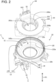
- FIG. 2 is an exploded perspective view of a fixed body 10 removed from a rotation body 20.
- the rotary connector device 100 includes the fixed body 10 and the rotation body 20.
- the rotation body 20 is assembled to the fixed body 10 so as to be rotatable about a rotation axis AX with respect to the fixed body 10.
- a first space S1 is defined between the fixed body 10 and the rotation body 20.
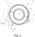
- FIG. 3 is a diagram illustrating an upper surface 10u of the fixed body 10 and for describing the arrangement of a cable 30 and a cable 32.
- the cable 30 and the cable 32 are disposed in the first space S1.
- a cable conductor wire 34 of the cable 30 (see FIGS. 4 and 7 ) has a first end connected to the fixed body 10 and a second end connected to the rotation body 20.
- the cable conductor wire 34 of the cable 32 has a first end connected to the fixed body 10 and a second end connected to the rotation body 20.
- the rotation body 20 can rotate about the rotation axis AX with respect to the fixed body 10.
- the number of cables provided in the rotary connector device 100 is not limited to two.
- the number of cables may be an even number, for example, four.
- the number of cables may be an odd number, for example, three.
- the rotary connector device 100 is used in, for example, a movable body (for example, an automobile) including a main body and a steering unit that is rotatable with respect to the main body.
- the fixed body 10 is attached to the main body of the movable body.
- the rotation body 20 is attached to the steering unit.
- the first end of the cable conductor wire 34 of the cable 30 and the first end of the cable conductor wire 34 of the cable 32 are electrically connected to an electronic device provided in the main body of the movable body.
- the second end of the cable conductor wire 34 of the cable 30 and the second end of the cable conductor wire 34 of the cable 32 are electrically connected to an electronic device (for example, a switch) provided in the steering unit.
- the rotary connector device 100 transmits/receives power or electrical signals to/from the electronic device provided in the main body of the movable body and the electronic device provided in the steering unit.
- the rotary connector device 100 may be used in a device other than a movable body.
- the fixed body 10 is provided with a first fixed body portion 12 and a second fixed body portion 14.
- the second fixed body portion 14 is coupled to the first fixed body portion 12 with the second fixed body portion 14 disposed above the first fixed body portion 12.
- the first fixed body portion 12 forms a bottom portion 10b of the fixed body 10.
- the second fixed body portion 14 forms a side wall 10l of the fixed body 10.
- the first fixed body portion 12 includes a first ring portion 120 and a first extending portion 122.
- the first ring portion 120 has a ring shape when the rotary connector device 100 is viewed in a first direction D1 along the rotation axis AX.
- the first ring portion 120 is disposed such that the rotation axis AX passes through the center of the first ring portion 120.
- the first extending portion 122 extends outward of an outer periphery 120a of the first ring portion 120 in the radial direction of the rotation axis AX.
- the second fixed body portion 14 includes an outer-circumferential cylindrical portion 140 and a second extending portion 142.
- the outer-circumferential cylindrical portion 140 is disposed such that a hollow portion 140a of the outer-circumferential cylindrical portion 140 extends in the first direction D1.
- the outer-circumferential cylindrical portion 140 extends upward from the outer periphery 120a of the first ring portion 120 in the first direction D1.
- the second extending portion 142 extends outward from the outer-circumferential cylindrical portion 140 in the radial direction of the rotation axis AX.
- the second extending portion 142 faces the first extending portion 122 in the first direction D1. Details of coupling between the first extending portion 122 and the second extending portion 142 are described later.
- the rotation body 20 includes a second ring portion 200 and an inner-circumferential cylindrical portion 202.
- the second ring portion 200 has a ring shape when the rotary connector device 100 is viewed in the first direction D1.
- the second ring portion 200 is disposed such that the rotation axis AX passes through the center of the second ring portion 200.
- the inner-circumferential cylindrical portion 202 is disposed such that a hollow portion 202a of the inner-circumferential cylindrical portion 202 extends in the first direction D1.
- the inner-circumferential cylindrical portion 202 extends downward from an inner periphery 200a of the second ring portion 200 in the first direction D1.
- the inner-circumferential cylindrical portion 202 is disposed inward of the outer-circumferential cylindrical portion 140 in the radial direction of the rotation axis AX.
- the first space S1 is defined by the first ring portion 120, the outer-circumferential cylindrical portion 140, the second ring portion 200, and the inner-circumferential cylindrical portion 202. That is, the first ring portion 120, the outer-circumferential cylindrical portion 140, the second ring portion 200, and the inner-circumferential cylindrical portion 202 face each other to define the first space S1.
- the first space S1 is equal to a space in which the hollow portion 202a of the inner-circumferential cylindrical portion 202 is excluded from the hollow portion 140a of the outer-circumferential cylindrical portion 140. Note that the first space S1 is included in a space S between the first fixed body portion 12 and the second fixed body portion 14.
- the inner-circumferential cylindrical portion 202 is engaged with an assembly member 90 (see FIG. 1 ).
- the assembly member 90 is disposed below the fixed body 10 in the first direction D1 and is rotatable about the rotation axis AX.
- the rotation body 20 is assembled to the fixed body 10 such that the rotation body 20 and the assembly member 90 sandwich the fixed body 10 in the first direction D1. Note that the assembly member 90 may be omitted.
- the inner-circumferential cylindrical portion 202 is provided in the rotation body 20.
- the inner-circumferential cylindrical portion 202 may be provided in the fixed body 10.
- the rotary connector device 100 has a shape including the hollow portion 202a, but the rotary connector device 100 need not include the hollow portion 202a.
- the rotary connector device 100 includes a first connector 40 and a second connector 42.
- the first connector 40 is connected to an external cable extending from the main body of a movable body, for example.
- the second connector 42 is connected to an external cable extending from the steering unit of a movable body, for example.
- the first connector 40 and the second connector 42 are electrically connected via the cable 30 and the cable 32.
- the first connector 40 is connected to the fixed body 10.
- the first connector 40 is disposed outward of the fixed body 10 in a direction orthogonal to the first direction D1.
- the first connector 40 may be located below the fixed body 10 or above the fixed body 10.
- the first connector 40 is disposed outside the space S.
- the first connector 40 may be partially disposed inside the space S.
- the first connector 40 includes a plurality of first terminals 400 and a first cover 402.
- the plurality of first terminals 400 are electrically connected to terminals of the external cable.
- the first cover 402 is connected to the first extending portion 122 and the second extending portion 142.
- the first cover 402 covers the plurality of first terminals 400 so as to open on a side opposite to the first extending portion 122 and the second extending portion 142 in a direction orthogonal to the rotation axis AX.
- the second connector 42 is disposed on the rotation body 20. However, the position of the second connector 42 is not limited to the position illustrated in FIG. 1 .
- the second connector 42 is connected to the rotation body 20.
- the second connector 42 includes a plurality of second terminals 420 and a second cover 422.
- the plurality of second terminals 420 are electrically connected to an external cable.
- the second cover 422 is connected to an upper surface 200b of the second ring portion 200.
- the second cover 422 covers the plurality of second terminals 420 such that an upper portion of the second cover 422 is open.
- the second connector 42 is disposed outside the space S. However, the second connector 42 may be partially disposed inside the space S.
- FIG. 4 is a perspective view of the cable 30 and the first connector 40 for describing connection between the cable 30 and the first connector 40.
- the first cover 402 is omitted from FIG. 4 .
- the cable 32 has substantially the same configuration as the cable 30, the cable 32 is also omitted from FIG. 4 .
- the cable 30 and the cable 32 each have a flat shape.
- the cable 30 and the cable 32 are both flexible.
- the cable 30 and the cable 32 each include a plurality of the cable conductor wires 34 and an insulating covering member 36 that covers the plurality of cable conductor wires 34.
- the cable 30 and the cable 32 are wound along the outer peripheral surface of the inner-circumferential cylindrical portion 202 and the inner peripheral surface of the outer-circumferential cylindrical portion 140 in the first space S1.
- the cable 30 and the cable 32 are both wound in a direction that reverses partway.
- the cable 30 passes through a hole formed in the outer-circumferential cylindrical portion 140 such that a first end of the cable 30 is located in a second space S2 (see FIG. 2 ) surrounded by the first extending portion 122 and the second extending portion 142.
- the cable 30 passes through a hole formed in the second ring portion 200 such that a second end of the cable 30 is located in a third space S3 (see FIG. 2 ) covered by the second cover 422.
- the rotary connector device 100 includes a plurality of connection conductors 50 and an insulating supporting body 54.
- the plurality of connection conductors 50 are provided for electrically connecting the plurality of cable conductor wires 34 of the cable 30 and the plurality of first terminals 400.
- the insulating supporting body 54 supports the plurality of connection conductors 50 and the plurality of first terminals 400 of the first connector 40.
- the insulating supporting body 54 is attached to at least one of the first extending portion 122 and the second extending portion 142 in the second space S2.
- Each of the plurality of connection conductors 50 is electrically connected to each of the plurality of first terminals 400. As illustrated in FIG. 4 , first ends of the plurality of cable conductor wires 34 of the cable 30 are connected to the plurality of connection conductors 50, respectively. The plurality of first ends of the plurality of cable conductor wires 34 and the plurality of connection conductors 50 are connected to each other by welding. However, the plurality of first ends of the plurality of cable conductor wires 34 and the plurality of connection conductors 50 may be connected to each other by a method other than welding. For example, the plurality of first ends of the plurality of cable conductor wires 34 and the plurality of connection conductors 50 may be crimped by using a cover member. Each of the plurality of first ends of the plurality of cable conductor wires 34 of the cable 32 are connected to each of the plurality of connection conductors 52 supported by an insulating supporting body 56 (see FIG. 7 ).
- Each of the plurality of second ends of the plurality of cable conductor wires 34 of the cable 30 is electrically connected to each of the plurality of second terminals 420 of the second connector 42.
- Each of the plurality of second ends of the cable conductor wires 34 of the cable 32 is electrically connected to each of the plurality of second terminals 420 of the second connector 42.
- connection conductors 50 and the number of cable conductor wires 34 are not limited to the example illustrated in FIG. 4 .
- the rotary connector device 100 may include only one connection conductor 50.
- the rotary connector device 100 may include only one cable conductor wire 34.
- FIG. 5 is a side view of the rotary connector device 100. As illustrated in FIG. 5 , the first fixed body portion 12 and the second fixed body portion 14 are coupled together at a coupling portion 16. The coupling portion 16 is exposed to an outer surface 10s of the fixed body 10.
- the outer surface 10s of the fixed body 10 is configured by the outer surfaces of at least the first ring portion 120, the outer-circumferential cylindrical portion 140, the first extending portion 122, and the second extending portion 142.
- the coupling portion 16 includes a first coupling portion 160 and a second coupling portion 162.
- the first extending portion 122 and the second extending portion 142 are coupled in the first direction D1.
- the first ring portion 120 and the outer-circumferential cylindrical portion 140 are coupled in the first direction D1.
- the fixed body 10 is provided with a plurality of engagement portions 18 that engage the first fixed body portion 12 with the second fixed body portion 14 while the first fixed body portion 12 and the second fixed body portion 14 are coupled.
- the plurality of engagement portions 18 are disposed along an outer periphery 10o of the fixed body 10 when the fixed body 10 is viewed in the first direction D1. In other words, the plurality of engagement portions 18 are disposed along the first coupling portion 160 and the second coupling portion 162 that are exposed to the outer surface 10s of the fixed body 10.
- the engagement portion 18 includes an engagement frame 180 and an engagement claw 188.
- the engagement frame 180 is attached to the first fixed body portion 12.
- the engagement claw 188 is attached to the second fixed body portion 14.
- the engagement frame 180 may be attached to the second fixed body portion 14, and the engagement claw 188 may be attached to the first fixed body portion 12.
- the engagement frame 180 includes a first frame piece 182, a second frame piece 184, and a connection piece 186.
- the first frame piece 182 and the second frame piece 184 each extend upward from the outer periphery 120a of the first ring portion 120 of the first fixed body portion 12 or the outer periphery of the first extending portion 122.
- the connection piece 186 extends in a direction orthogonal to the first direction D1 and along the outer periphery 10o, and connects an upper end of the first frame piece 182 and an upper end of the second frame piece 184.
- the engagement claw 188 is hooked on the connection piece 186 between the first frame piece 182 and the second frame piece 184.
- the engagement frame 180 is integrally formed with either the first ring portion 120 or the first extending portion 122.
- the engagement claw 188 is integrally formed with either the outer-circumferential cylindrical portion 140 or the second extending portion 142.
- the engagement portion 18 is not limited to the structure disclosed in the present embodiment. Furthermore, the plurality of engagement portions 18 may be omitted.
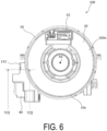
- FIG. 6 is a diagram illustrating a top surface 100u of the rotary connector device 100.
- FIG. 7 is a cross-sectional view of the rotary connector device 100 taken along the line VII-VII in FIG. 6 .
- the fixed body 10 includes a first wall 124, a second wall 144, and a third wall 146.
- the first wall 124, the second wall 144, and the third wall 146 define the second space S2.
- the second space S2 is included in the space S between the first fixed body portion 12 and the second fixed body portion 14.
- the second space S2 is also defined by the outer-circumferential cylindrical portion 140.
- the second space S2 may be defined without the outer-circumferential cylindrical portion 140.
- the first wall 124 extends outward from the outer periphery 120a of the first ring portion 120 in the radial direction of the rotation axis AX.
- the second wall 144 extends outward from the outer-circumferential cylindrical portion 140 in the radial direction of the rotation axis AX.
- the second wall 144 faces the first wall 124 in the first direction D1.
- the third wall 146 is parallel to the first direction D1 and is connected to the second wall 144.
- the third wall 146 extends to the first wall 124 in the first direction D1.
- the third wall 146 and the first wall 124 are coupled in the first direction D1.
- the first coupling portion 160 is exposed to an outer surface 124o of the first wall 124 and an outer surface 146o of the third wall 146.
- the first extending portion 122 includes the first wall 124
- the second extending portion 142 includes the second wall 144 and the third wall 146.
- the structure for defining the second space S2 is not limited thereto.
- the insulating supporting body 54 and the insulating supporting body 56 are aligned in a second direction D2 orthogonal to the rotation axis AX.
- the insulating supporting body 54 is closer to the first coupling portion 160 than the insulating supporting body 56 in the second direction D2. That is, each of the plurality of connection conductors 50 supported by the insulating supporting body 54 is closer to the first coupling portion 160 in the second direction D2 than each of the plurality of connection conductors 52 supported by the insulating supporting body 56.
- the rotary connector device 100 includes an inhibiting structure 60 that inhibits foreign matter from entering the space S through the coupling portion 16. More specifically, as illustrated in FIG. 7 , the inhibiting structure 60 includes a protecting member 62 for inhibiting the entry of foreign matter into the second space S2 through the first coupling portion 160.
- the protecting member 62 is disposed between the first coupling portion 160 and the plurality of connection conductors 50. Specifically, the protecting member 62 is disposed such that the first coupling portion 160, the protecting member 62, and each connection conductor 50 overlap when the fixed body 10 is viewed in each direction from the first coupling portion 160 to each connection conductor 50.
- the protecting member 62 is disposed such that the first coupling portion 160, the protecting member 62, and a connection conductor 50A, which is the closest connection conductor 50 to the first coupling portion 160, overlap when the fixed body 10 is viewed in a direction from the first coupling portion 160 to the connection conductor 50A.
- the protecting member 62 is disposed between the plurality of connection conductors 50 and an engagement portion 18 of the plurality of engagement portions 18 that is closest to the plurality of connection conductors 50. In other words, the protecting member 62 faces the engagement portion 18 closest to the plurality of connection conductors 50 via the third wall 146.
- the protecting member 62 extends upward from the first wall 124 in the first direction D1. With this configuration, a gap passageway between the first coupling portion 160 and the plurality of connection conductors 50 is long in the first direction D1.
- the length of the protecting member 62 in the first direction D1 is not limited to the length illustrated in FIG. 7 .
- the length of the protecting member 62 in the first direction D1 may be equal to the length of the protecting member 62 in the second direction D2.
- the protecting member 62 may extend downward from the second wall 144 in the first direction D1 provided that the protecting member 62 is located between the first coupling portion 160 and the plurality of connection conductors 50.
- the protecting member 62 includes a first surface 64 and a second surface 66 that are parallel with the first direction D1 and that face each other in the second direction D2.
- the first surface 64 faces the insulating supporting body 54.
- the second surface 66 faces the first coupling portion 160.
- the second surface 66 is in contact with an inner surface 124i of the first wall 124 and an inner surface 146i of the third wall 146 so as to connect the inner surface 124i and the inner surface 146i.
- the second surface 66 covers the first coupling portion 160.
- the inner surface 124i and the inner surface 146i constitute the inner surface of the fixed body 10.
- the second surface 66 may not be in contact with the inner surface 124i and the inner surface 146i, or may be in contact with either of the inner surface 124i and the inner surface 146i.
- the protecting member 62 includes an insulating material.
- the protecting member 62 and the first fixed body portion 12 are integrally formed of a resin.
- FIG. 8 is a side view of the fixed body 10 for describing the length of the protecting member 62 and the length of the engagement portion 18.
- the dotted line in FIG. 8 indicates the protecting member 62.
- the protecting member 62 has a length L1 in a third direction D3.
- the third direction D3 is orthogonal to the first direction D1 and follows the outer surface 146o of the third wall 146.
- the length L1 of the protecting member 62 in the third direction D3 is greater than a length L2 of the engagement portion 18 in the third direction D3.
- the gap passageway from the first coupling portion 160 between the first frame piece 182 and the second frame piece 184 to the plurality of connection conductors 50 is long in the third direction D3.
- the length L1 of the protecting member 62 in the third direction D3 is not limited to the example illustrated in FIG. 8 .
- the length L1 of the protecting member 62 in the third direction D3 may be longer than the length L3 of the first coupling portion 160 between the first frame piece 182 and the second frame piece 184 in the third direction D3, or may be shorter than the length L2.
- the length L1 in the third direction D3 may be shorter than the length L3 in the third direction D3.
- the protecting member 62 may be provided along the entire outer circumference of the first extending portion 122 and the second extending portion 142 along the third wall 146.
- the rotary connector device 100 includes the cable 30, the cable 32, the first connector 40, and the second connector 42, but the cable 30, the cable 32, the first connector 40, and the second connector 42 may be omitted.
- connection conductor 50 is attached to the fixed body 10 by way of the insulating supporting body 54, but the insulating supporting body 54 may be omitted.
- the connection conductor 50 may be directly attached to the fixed body 10.
- the fixed body 10 may include a plurality of protecting members 62.
- a plurality of protecting members 62 may be disposed so as to face, via the third wall 146, the plurality of engagement portions 18 arranged in order of proximity to the plurality of connection conductors 50.
- the protecting members 62 need not face the engagement portions 18 via the third wall 146.
- the inhibiting structure 60 includes an inhibiting portion 600 configured to inhibit the entry of foreign matter into the first space S1 through the second coupling portion 162.
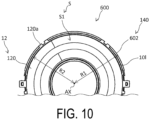
- FIG. 10 is a cross-sectional view of the fixed body 10 in a plane orthogonal to the rotation axis AX for illustrating the inhibiting portion 600.
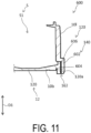
- FIG. 11 is a cross-sectional view of the fixed body 10 in a plane parallel to the radial direction of the rotation axis AX and the first direction D1 for illustrating the inhibiting portion 600.
- the inhibiting portion 600 is configured by the outer-circumferential cylindrical portion 140 and the outer periphery 120a of the first ring portion 120 coming into contact with each other such that the outer-circumferential cylindrical portion 140 is outside the outer periphery 120a in the radial direction of the rotation axis AX.
- the inhibiting portion 600 is provided separately from the engagement portion 18.
- the outer-circumferential cylindrical portion 140 includes a large diameter portion 602 that is in contact with the outer periphery 120a of the first ring portion 120.
- a diameter R1 of the large diameter portion 602 is larger than the diameter of the outer-circumferential cylindrical portion 140 anywhere other than at the large diameter portion 602.
- the diameter R1 of the large diameter portion 602 is larger than a diameter R2 of the outer periphery 120a.
- the large diameter portion 602 need not be provided.
- the outer-circumferential cylindrical portion 140 covers the outer periphery 120a of the first ring portion 120 in the radial direction of the rotation axis AX.
- the second coupling portion 162 is exposed at the bottom portion 10b of the fixed body 10 and is not exposed at the side wall 10l of the fixed body 10.
- the first ring portion 120 includes an extending portion 606 that extends in the first direction D1.
- the outer periphery 120a of the first ring portion 120 is constituted by the outer periphery of the extending portion 606.
- a surface 604 of the large diameter portion 602 is in contact with the extending portion 606 that extends in the first direction D1.
- a pathway from the second coupling portion 162 to the first space S1 is long in the first direction D1.
- the surface 604 need not be in contact with the extending portion 606.
- the extending portion 606 may be omitted.
- the rotary connector device 100 and features of the rotary connector device 100 are summarized below.
- the rotary connector device 100 includes the fixed body 10, the rotation body 20, and the inhibiting structure 60.
- the fixed body 10 is configured by the first fixed body portion 12 and the second fixed body portion 14 disposed facing each other with the space S being defined between the first fixed body portion 12 and the second fixed body portion 14, and coupled at the coupling portion 16.
- the coupling portion 16 is exposed to the outer surface 10s of the fixed body 10.
- the inhibiting structure 60 inhibits foreign matter from entering the space S between the first fixed body portion 12 and the second fixed body portion 14. With this configuration, deterioration of the rotary connector device 100 due to the entry of foreign matter is inhibited. As a result, the environmental resistance of the rotary connector device 100 is improved.
- the foreign matter is, for example, fluid water and dust.
- the rotary connector device 100 further includes the connection conductor 50 disposed on the fixed body 10 in the second space S2 included in the space S.
- the connection conductor 50 is connected to a first end of the cable conductor wire 34, and the rotation body 20 is connected to a second end of the cable conductor wire 34.
- connection conductor 50 With this configuration, foreign matter is inhibited from adhering to the connection conductor 50, and the connection conductor 50 is prevented from degrading.
- the inhibiting structure 60 includes the protecting member 62 configured to increase the length of the gap passageway between the coupling portion 16 and the connection conductor 50. This configuration can inhibit foreign matter from reaching the connection conductor 50.
- the inhibiting structure 60 includes the protecting member 62 disposed between the coupling portion 16 and the connection conductor 50 in the second space S2 included in the space S. This configuration can inhibit foreign matter from reaching the connection conductor 50.
- the protecting member 62 is in contact with at least one of the inner surface 124i of the first fixed body portion 12 and the inner surface 146i of the second fixed body portion 14 at the coupling portion 16. With this configuration, entry of foreign matter is inhibited because the protecting member 62 is disposed to fill the coupling portion 16.
- the rotation body 20 is rotatable about the rotation axis AX in the first direction D1.
- the coupling portion 16 is provided on the outer periphery 10o of the fixed body 10 when viewed in the first direction D1.
- the protecting member 62 is disposed between the coupling portion 16 and the connection conductor 50 in the second direction D2 orthogonal to the first direction D1.
- the protecting member 62 extends from the first fixed body portion 12 in the first direction D1. This configuration inhibits foreign matter from flowing around the protecting member 62 because the gap passageway between the coupling portion 16 and the connection conductor 50 extends in the first direction D1.
- the fixed body 10 includes the engagement portion 18 configured to engage the first fixed body portion 12 and the second fixed body portion 14.
- the protecting member 62 is disposed between the engagement portion 18 and the connection conductor 50.
- the length L1 of the protecting member in the third direction D3 orthogonal to the first direction D1 and following the outer surface 10s of the fixed body 10 is longer than the length L2 of the engagement portion 18 in the third direction D3.
- This configuration can inhibit foreign matter from flowing around the protecting member 62 that is long in the third direction D3, even in a case where foreign matter enters at the coupling portion 16 in the vicinity of the engagement portion 18.
- the engagement portion 18 includes the engagement frame 180 attached to one of the first fixed body portion 12 and the second fixed body portion 14, and the engagement claw 188 attached to the other of the first fixed body portion 12 and the second fixed body portion 14. Even in a case where engagement between the engagement frame 180 and the engagement claw 188 loosens, the protecting member 62 is disposed corresponding to the engagement portion 18, and thus this configuration can effectively inhibit the entry of foreign matter.
- the protecting member 62 includes an insulating material. With this configuration, even in a case where the protecting member 62 is in contact with the connection conductor 50, electrical connection problems such as short-circuiting can be inhibited.
- the rotary connector device 100 includes the first connector 40 provided on the outside of the fixed body 10 and including the first terminal 400 electrically connected to the connection conductor 50. This configuration improves connectivity between the rotary connector device 100 and an external cable.
- the rotary connector device 100 includes the insulating supporting body 54 that supports the connection conductor 50 and is attached to the fixed body 10 in the space S. This configuration can inhibit electrical connection problems such as short-circuiting between the connection conductor 50 and another conductor.
- the space S includes the first space S1 and the second space S2.
- the rotation body 20 is disposed corresponding to the first space S1.
- the connection conductor 50 is disposed in the second space S2.
- the cable 30 includes the cable conductor wire 34 and the insulating covering member 36 covering the cable conductor wire 34.
- the cable 30 is disposed in a space (first space S1) between the rotation body 20 and the fixed body 10.
- the inhibiting structure 60 includes the inhibiting portion 600 configured by the second fixed body portion 14 covering the first fixed body portion 12 in the radial direction of the rotation axis AX.
- the surface 604 of the second fixed body portion 14 and the outer periphery 120a of the first ring portion 120 of the first fixed body portion 12 are in contact with each other.
- FIG. 9 is a cross-sectional view corresponding to the cross-sectional view illustrated in FIG. 7 .
- the rotary connector device according to the second embodiment differs from the rotary connector device 100 according to the first embodiment in terms of the structure defining the second space S2 and the configuration of a protecting member 70 (corresponds to the protecting member 62). Descriptions of identical configurations are omitted.
- the second space S2 is defined by the first wall 124, the second wall 144, a third wall 170, and a fourth wall 172.
- the third wall 170 extends upward from the first wall 124.
- the fourth wall 172 extends downward from the second wall 144.
- An upper end of the third wall 170 and a lower end of the fourth wall 172 are coupled at a first coupling portion 160a.
- the first coupling portion 160a is separated from the first wall 124 and the second wall 144 in the first direction D1.
- the protecting member 70 differs from the protecting member 62 in terms of position in the first direction D1. Further, unlike the protecting member 62, the protecting member 70 is provided separately from the first wall 124. As illustrated in FIG. 9 , the protecting member 70 is separated from the first wall 124 and the second wall 144 in the first direction D1 so as to face the first coupling portion 160a.
- a length L11 of the protecting member 70 in the first direction D1 includes a length L12 from a position facing the first coupling portion 160a in the second direction D2 to a lower end of the protecting member 70, and a length L13 from a position facing the first coupling portion 160a in the second direction D2 to an upper end of the protecting member 70.
- the length L12 is longer than the length L13.
- the gap passageway extending from the first coupling portion 160a to the plurality of connection conductors 50 around a lower portion of the protecting member 70 is longer than a gap passageway extending from the first coupling portion 160a to the plurality of connection conductors 50 around an upper portion of the protecting member 70. Therefore, this configuration effectively inhibits foreign matter from reaching the plurality of connection conductors 50, even in a case where foreign matter that has entered through the first coupling portion 160a easily moves downward.
- the length L11, the length L12, and the length L13 of the protecting member 70 are not limited to those illustrated in FIG. 9 .
Description
- The technology disclosed in the present application relates to a rotary connector device.
- A known rotary connector device includes a fixed body, a rotation body rotatably attached to the fixed body, a fixed body-side connector, and a rotation body-side connector (for example, see
WO 2017/221820 A1 ). The rotary connector device disclosed inWO 2017/221820 A1 further includes a cable conductor wire that is housed in a space between the fixed body and the rotation body and that electrically connects the fixed body-side connector and the rotation body-side connector. - More specifically, the fixed body disclosed in
WO 2017/221820 A1 is a stator main body and a sub-stator that are coupled together to form a space therebetween. -
WO 2017/170752 A1 shows a rotary connector device according to the preamble ofclaim 1. - In the rotary connector device disclosed in
WO 2017/221820 A1 , foreign matter may enter the space between the stator main body and the sub-stator to degrade performance of the rotary connector device. - In light of this, an object of the technology disclosed in the present application is to increase the environmental resistance of a rotary connector device.
- The invention provides a rotary connector device according to
claim 1, wherein the foreign matter is, for example, fluid water and dust so that the rotary connector device prevents foreign matter from entering the space. As a result, the environmental resistance of the rotary connector device is improved. Further, as the connection conductor is disposed on the fixed body in the second space, and the rotation body is connected to the second end of the cable conductor wire, foreign matter is prevented from adhering to the connection conductor, and thus deterioration of the connection conductor is inhibited. - Further, as the inhibiting structure includes a protecting member configured to increase a length of a gap passageway between the coupling portion and the connection conductor, foreign matter is less likely to reach the connection conductor.
- Further, in the rotary connector device, the protecting member may be in contact with at least one of an inner surface of the first fixed body portion and an inner surface of the second fixed body portion at the coupling portion. With this configuration, the entry of foreign matter is inhibited because the protecting member is disposed covering the coupling portion.
- Further, in the rotary connector device, the rotation body may be rotatable about a rotation axis along a first direction, the coupling portion may be provided on an outer periphery of the fixed body when viewed in the first direction, the protecting member may be disposed between the coupling portion and the connection conductor in a second direction substantially orthogonal to the first direction, and the protecting member may extend from the first fixed body portion or the second fixed body portion in the first direction. This configuration inhibits foreign matter from flowing around the protecting member extending in the first direction.
- Further, in the rotary connector device, the fixed body may include an engagement portion configured to engage the first fixed body portion and the second fixed body portion with each other, and the protecting member may be disposed between the engagement portion and the connection conductor in the second direction. Even in a case where foreign matter is likely to enter at the coupling portion in the vicinity of the engagement portion, the protecting member is disposed corresponding to the coupling portion at the position where foreign matter is likely to enter. Thus, this configuration can effectively inhibit the entry of foreign matter.
- Further, in the rotary connector device, a length of the protecting member in a third direction substantially orthogonal to the first direction and following the outer surface may be longer than a length of the engagement portion in the third direction. This configuration can prevent foreign matter from flowing around the protecting member that is long in the third direction even in a case where foreign matter enters from the coupling portion in the vicinity of the engagement portion.
- Further, in the rotary connector device, the engagement portion may include an engagement frame attached to one of the first fixed body portion and the second fixed body portion, and an engagement claw attached to the other of the first fixed body portion and the second fixed body portion. Even in a case where engagement between the engagement frame and the engagement claw is loosened, this configuration can effectively inhibit the entry of foreign matter because the protecting member is disposed at a position corresponding to the engagement portion.
- Further, in the rotary connector device, the protecting member may include an insulating material. This configuration can inhibit electrical connection problems such as short-circuiting even in a case where the protecting member is in contact with the connection conductor.
- Further, the rotary connector device may include a first connector disposed outside the fixed body and including a terminal electrically connected to the connection conductor. This configuration improves connectivity between the rotary connector device and an external cable.
- Further, in the rotary connector device, the first connector may be partially disposed in the second space.
- Further, the rotary connector device may include an insulating supporting body configured to support the connection conductor and attached to the fixed body in the space. This configuration can inhibit electrical connection problems such as short-circuiting of the connection conductor.
- Further, in the rotary connector device, the space includes a first space and a second space, the rotation body is disposed corresponding to the first space, and the connection conductor is disposed in the second space.
- Further, in the rotary connector device the cable includes the cable conductor wire, and an insulating covering member covering the cable conductor wire, the cable being disposed in a space between the rotation body and the fixed body.
- Further, in the rotary connector device, the inhibiting structure includes an inhibiting portion configured by the second fixed body portion covering the first fixed body portion in a radial direction of the rotation axis of the rotation body.
- With this configuration, foreign matter entering from outside in the radial direction of the rotation axis is inhibited from entering the space.
- Further, in the rotary connector device, a surface of the second fixed body portion may be in contact with an outer periphery of the first fixed body portion in the radial direction.
- With this configuration, foreign matter is effectively inhibited from entering the space because the passageway from the coupling portion to the space is narrow.
- Further, the fixed body of the rotary connector device includes a first fixed body portion, a second fixed body portion disposed facing the first fixed body portion with the space being defined between the second fixed body portion and the first fixed body portion, and coupled to the first fixed body portion at a coupling portion, and an inhibiting structure configured to inhibit foreign matter from entering the space through the coupling portion. The coupling portion is exposed to outer surfaces of the first fixed body portion and the second fixed body portion, and the first fixed body portion and the second fixed body portion are connected to a rotation body rotatably assembled to the first fixed body portion and the second fixed body portion.
- This configuration inhibits the entry of foreign matter into the space, thereby improving the environmental resistance of the rotary connector device.
- The technology disclosed in the present application can enhance the environmental resistance of a rotary connector device.
-
-
FIG. 1 is a perspective view of a rotary connector device according to a first embodiment. -
FIG. 2 is an exploded perspective view of a fixed body removed from a rotation body. -
FIG. 3 is a top view of the fixed body for describing the arrangement of cables. -
FIG. 4 is a perspective view of a cable and a first connector for describing connection between the cable and the first connector. -
FIG. 5 is a side view of the rotary connector device. -
FIG. 6 is a top view of the rotary connector device. -
FIG. 7 is a cross-sectional view of the rotary connector device taken along the line VII-VII inFIG. 6 . -
FIG. 8 is a side view of the fixed body for describing the length of a protecting member and the length of an engagement portion. -
FIG. 9 is a cross-sectional view of a rotary connector device according to a second embodiment. -
FIG. 10 is a cross-sectional view of a fixed body for illustrating an inhibiting portion. -
FIG. 11 is a cross-sectional view of a fixed body for illustrating the inhibiting portion. - Next, embodiments will be described while referring to the drawings. The same reference numerals in the drawings indicate corresponding or identical configurations.
-
FIG. 1 is a perspective view of arotary connector device 100 according to a first embodiment.FIG. 2 is an exploded perspective view of afixed body 10 removed from arotation body 20. - As illustrated in
FIGS. 1 and2 , therotary connector device 100 includes thefixed body 10 and therotation body 20. Therotation body 20 is assembled to thefixed body 10 so as to be rotatable about a rotation axis AX with respect to thefixed body 10. When therotation body 20 is assembled to the fixedbody 10, a first space S1 is defined between the fixedbody 10 and therotation body 20. -
FIG. 3 is a diagram illustrating anupper surface 10u of the fixedbody 10 and for describing the arrangement of acable 30 and acable 32. As illustrated inFIG. 3 , thecable 30 and thecable 32 are disposed in the first space S1. Acable conductor wire 34 of the cable 30 (seeFIGS. 4 and7 ) has a first end connected to the fixedbody 10 and a second end connected to therotation body 20. Thecable conductor wire 34 of thecable 32 has a first end connected to the fixedbody 10 and a second end connected to therotation body 20. With thecable 30 and thecable 32 connected to the fixedbody 10 and therotation body 20, therotation body 20 can rotate about the rotation axis AX with respect to the fixedbody 10. The number of cables provided in therotary connector device 100 is not limited to two. The number of cables may be an even number, for example, four. In addition, the number of cables may be an odd number, for example, three. - The
rotary connector device 100 is used in, for example, a movable body (for example, an automobile) including a main body and a steering unit that is rotatable with respect to the main body. Specifically, the fixedbody 10 is attached to the main body of the movable body. Therotation body 20 is attached to the steering unit. The first end of thecable conductor wire 34 of thecable 30 and the first end of thecable conductor wire 34 of thecable 32 are electrically connected to an electronic device provided in the main body of the movable body. The second end of thecable conductor wire 34 of thecable 30 and the second end of thecable conductor wire 34 of thecable 32 are electrically connected to an electronic device (for example, a switch) provided in the steering unit. With this configuration, therotary connector device 100 transmits/receives power or electrical signals to/from the electronic device provided in the main body of the movable body and the electronic device provided in the steering unit. Therotary connector device 100 may be used in a device other than a movable body. - As illustrated in
FIGS. 2 and3 , the fixedbody 10 is provided with a firstfixed body portion 12 and a secondfixed body portion 14. The secondfixed body portion 14 is coupled to the firstfixed body portion 12 with the secondfixed body portion 14 disposed above the firstfixed body portion 12. The firstfixed body portion 12 forms abottom portion 10b of the fixedbody 10. The secondfixed body portion 14 forms a side wall 10l of the fixedbody 10. - As illustrated in
FIGS. 2 and3 , the firstfixed body portion 12 includes afirst ring portion 120 and a first extendingportion 122. Thefirst ring portion 120 has a ring shape when therotary connector device 100 is viewed in a first direction D1 along the rotation axis AX. Thefirst ring portion 120 is disposed such that the rotation axis AX passes through the center of thefirst ring portion 120. The first extendingportion 122 extends outward of anouter periphery 120a of thefirst ring portion 120 in the radial direction of the rotation axis AX. - The second
fixed body portion 14 includes an outer-circumferentialcylindrical portion 140 and a second extendingportion 142. The outer-circumferentialcylindrical portion 140 is disposed such that ahollow portion 140a of the outer-circumferentialcylindrical portion 140 extends in the first direction D1. The outer-circumferentialcylindrical portion 140 extends upward from theouter periphery 120a of thefirst ring portion 120 in the first direction D1. - The second extending
portion 142 extends outward from the outer-circumferentialcylindrical portion 140 in the radial direction of the rotation axis AX. The second extendingportion 142 faces the first extendingportion 122 in the first direction D1. Details of coupling between the first extendingportion 122 and the second extendingportion 142 are described later. - As illustrated in
FIG. 2 , therotation body 20 includes asecond ring portion 200 and an inner-circumferentialcylindrical portion 202. Thesecond ring portion 200 has a ring shape when therotary connector device 100 is viewed in the first direction D1. Thesecond ring portion 200 is disposed such that the rotation axis AX passes through the center of thesecond ring portion 200. The inner-circumferentialcylindrical portion 202 is disposed such that ahollow portion 202a of the inner-circumferentialcylindrical portion 202 extends in the first direction D1. The inner-circumferentialcylindrical portion 202 extends downward from aninner periphery 200a of thesecond ring portion 200 in the first direction D1. The inner-circumferentialcylindrical portion 202 is disposed inward of the outer-circumferentialcylindrical portion 140 in the radial direction of the rotation axis AX. With this configuration, the first space S1 is defined by thefirst ring portion 120, the outer-circumferentialcylindrical portion 140, thesecond ring portion 200, and the inner-circumferentialcylindrical portion 202. That is, thefirst ring portion 120, the outer-circumferentialcylindrical portion 140, thesecond ring portion 200, and the inner-circumferentialcylindrical portion 202 face each other to define the first space S1. In other words, the first space S1 is equal to a space in which thehollow portion 202a of the inner-circumferentialcylindrical portion 202 is excluded from thehollow portion 140a of the outer-circumferentialcylindrical portion 140. Note that the first space S1 is included in a space S between the firstfixed body portion 12 and the secondfixed body portion 14. - The inner-circumferential
cylindrical portion 202 is engaged with an assembly member 90 (seeFIG. 1 ). Theassembly member 90 is disposed below the fixedbody 10 in the first direction D1 and is rotatable about the rotation axis AX. Therotation body 20 is assembled to the fixedbody 10 such that therotation body 20 and theassembly member 90 sandwich the fixedbody 10 in the first direction D1. Note that theassembly member 90 may be omitted. - In the present embodiment, the inner-circumferential
cylindrical portion 202 is provided in therotation body 20. However, to define the first space S1, the inner-circumferentialcylindrical portion 202 may be provided in the fixedbody 10. - In the present embodiment, the
rotary connector device 100 has a shape including thehollow portion 202a, but therotary connector device 100 need not include thehollow portion 202a. - As illustrated in
FIG. 1 , therotary connector device 100 includes afirst connector 40 and asecond connector 42. Thefirst connector 40 is connected to an external cable extending from the main body of a movable body, for example. Thesecond connector 42 is connected to an external cable extending from the steering unit of a movable body, for example. Thefirst connector 40 and thesecond connector 42 are electrically connected via thecable 30 and thecable 32. - The
first connector 40 is connected to the fixedbody 10. In the present embodiment, thefirst connector 40 is disposed outward of the fixedbody 10 in a direction orthogonal to the first direction D1. However, thefirst connector 40 may be located below the fixedbody 10 or above the fixedbody 10. Thus, in the present embodiment, thefirst connector 40 is disposed outside the space S. However, thefirst connector 40 may be partially disposed inside the space S. - The
first connector 40 includes a plurality offirst terminals 400 and afirst cover 402. The plurality offirst terminals 400 are electrically connected to terminals of the external cable. Thefirst cover 402 is connected to the first extendingportion 122 and the second extendingportion 142. Thefirst cover 402 covers the plurality offirst terminals 400 so as to open on a side opposite to the first extendingportion 122 and the second extendingportion 142 in a direction orthogonal to the rotation axis AX. - The
second connector 42 is disposed on therotation body 20. However, the position of thesecond connector 42 is not limited to the position illustrated inFIG. 1 . Thesecond connector 42 is connected to therotation body 20. Thesecond connector 42 includes a plurality ofsecond terminals 420 and asecond cover 422. The plurality ofsecond terminals 420 are electrically connected to an external cable. Thesecond cover 422 is connected to anupper surface 200b of thesecond ring portion 200. Thesecond cover 422 covers the plurality ofsecond terminals 420 such that an upper portion of thesecond cover 422 is open. In the present embodiment, thesecond connector 42 is disposed outside the space S. However, thesecond connector 42 may be partially disposed inside the space S. -
FIG. 4 is a perspective view of thecable 30 and thefirst connector 40 for describing connection between thecable 30 and thefirst connector 40. However, thefirst cover 402 is omitted fromFIG. 4 . Further, because thecable 32 has substantially the same configuration as thecable 30, thecable 32 is also omitted fromFIG. 4 . - The
cable 30 and thecable 32 each have a flat shape. Thecable 30 and thecable 32 are both flexible. Thecable 30 and thecable 32 each include a plurality of thecable conductor wires 34 and an insulatingcovering member 36 that covers the plurality ofcable conductor wires 34. As illustrated inFIG. 3 , thecable 30 and thecable 32 are wound along the outer peripheral surface of the inner-circumferentialcylindrical portion 202 and the inner peripheral surface of the outer-circumferentialcylindrical portion 140 in the first space S1. As illustrated inFIG. 3 , thecable 30 and thecable 32 are both wound in a direction that reverses partway. - The
cable 30 passes through a hole formed in the outer-circumferentialcylindrical portion 140 such that a first end of thecable 30 is located in a second space S2 (seeFIG. 2 ) surrounded by the first extendingportion 122 and the second extendingportion 142. Thecable 30 passes through a hole formed in thesecond ring portion 200 such that a second end of thecable 30 is located in a third space S3 (seeFIG. 2 ) covered by thesecond cover 422. - As illustrated in
FIG. 4 , therotary connector device 100 includes a plurality ofconnection conductors 50 and an insulating supportingbody 54. The plurality ofconnection conductors 50 are provided for electrically connecting the plurality ofcable conductor wires 34 of thecable 30 and the plurality offirst terminals 400. The insulating supportingbody 54 supports the plurality ofconnection conductors 50 and the plurality offirst terminals 400 of thefirst connector 40. The insulating supportingbody 54 is attached to at least one of the first extendingportion 122 and the second extendingportion 142 in the second space S2. - Each of the plurality of
connection conductors 50 is electrically connected to each of the plurality offirst terminals 400. As illustrated inFIG. 4 , first ends of the plurality ofcable conductor wires 34 of thecable 30 are connected to the plurality ofconnection conductors 50, respectively. The plurality of first ends of the plurality ofcable conductor wires 34 and the plurality ofconnection conductors 50 are connected to each other by welding. However, the plurality of first ends of the plurality ofcable conductor wires 34 and the plurality ofconnection conductors 50 may be connected to each other by a method other than welding. For example, the plurality of first ends of the plurality ofcable conductor wires 34 and the plurality ofconnection conductors 50 may be crimped by using a cover member. Each of the plurality of first ends of the plurality ofcable conductor wires 34 of thecable 32 are connected to each of the plurality ofconnection conductors 52 supported by an insulating supporting body 56 (seeFIG. 7 ). - Each of the plurality of second ends of the plurality of
cable conductor wires 34 of thecable 30 is electrically connected to each of the plurality ofsecond terminals 420 of thesecond connector 42. Each of the plurality of second ends of thecable conductor wires 34 of thecable 32 is electrically connected to each of the plurality ofsecond terminals 420 of thesecond connector 42. - Note that the number of
connection conductors 50 and the number ofcable conductor wires 34 are not limited to the example illustrated inFIG. 4 . Therotary connector device 100 may include only oneconnection conductor 50. Therotary connector device 100 may include only onecable conductor wire 34. -
FIG. 5 is a side view of therotary connector device 100. As illustrated inFIG. 5 , the firstfixed body portion 12 and the secondfixed body portion 14 are coupled together at acoupling portion 16. Thecoupling portion 16 is exposed to anouter surface 10s of the fixedbody 10. Theouter surface 10s of the fixedbody 10 is configured by the outer surfaces of at least thefirst ring portion 120, the outer-circumferentialcylindrical portion 140, the first extendingportion 122, and the second extendingportion 142. - As illustrated in
FIG. 5 , thecoupling portion 16 includes afirst coupling portion 160 and asecond coupling portion 162. At thefirst coupling portion 160, the first extendingportion 122 and the second extendingportion 142 are coupled in the first direction D1. At thesecond coupling portion 162, thefirst ring portion 120 and the outer-circumferentialcylindrical portion 140 are coupled in the first direction D1. - As illustrated in
FIG. 5 , the fixedbody 10 is provided with a plurality ofengagement portions 18 that engage the firstfixed body portion 12 with the secondfixed body portion 14 while the firstfixed body portion 12 and the secondfixed body portion 14 are coupled. The plurality ofengagement portions 18 are disposed along an outer periphery 10o of the fixedbody 10 when the fixedbody 10 is viewed in the first direction D1. In other words, the plurality ofengagement portions 18 are disposed along thefirst coupling portion 160 and thesecond coupling portion 162 that are exposed to theouter surface 10s of the fixedbody 10. - The
engagement portion 18 includes anengagement frame 180 and anengagement claw 188. Theengagement frame 180 is attached to the firstfixed body portion 12. Theengagement claw 188 is attached to the secondfixed body portion 14. However, theengagement frame 180 may be attached to the secondfixed body portion 14, and theengagement claw 188 may be attached to the firstfixed body portion 12. - The
engagement frame 180 includes afirst frame piece 182, asecond frame piece 184, and aconnection piece 186. Thefirst frame piece 182 and thesecond frame piece 184 each extend upward from theouter periphery 120a of thefirst ring portion 120 of the firstfixed body portion 12 or the outer periphery of the first extendingportion 122. Theconnection piece 186 extends in a direction orthogonal to the first direction D1 and along the outer periphery 10o, and connects an upper end of thefirst frame piece 182 and an upper end of thesecond frame piece 184. Theengagement claw 188 is hooked on theconnection piece 186 between thefirst frame piece 182 and thesecond frame piece 184. - In the present embodiment, the
engagement frame 180 is integrally formed with either thefirst ring portion 120 or the first extendingportion 122. Theengagement claw 188 is integrally formed with either the outer-circumferentialcylindrical portion 140 or the second extendingportion 142. However, theengagement portion 18 is not limited to the structure disclosed in the present embodiment. Furthermore, the plurality ofengagement portions 18 may be omitted. - Details of the
first coupling portion 160 will be described with reference toFIGS. 6 and7 .FIG. 6 is a diagram illustrating atop surface 100u of therotary connector device 100.FIG. 7 is a cross-sectional view of therotary connector device 100 taken along the line VII-VII inFIG. 6 . - As illustrated in
FIG. 7 , the fixedbody 10 includes afirst wall 124, asecond wall 144, and athird wall 146. Thefirst wall 124, thesecond wall 144, and thethird wall 146 define the second space S2. Note that the second space S2 is included in the space S between the firstfixed body portion 12 and the secondfixed body portion 14. In the present embodiment, the second space S2 is also defined by the outer-circumferentialcylindrical portion 140. However, the second space S2 may be defined without the outer-circumferentialcylindrical portion 140. - The
first wall 124 extends outward from theouter periphery 120a of thefirst ring portion 120 in the radial direction of the rotation axis AX. Thesecond wall 144 extends outward from the outer-circumferentialcylindrical portion 140 in the radial direction of the rotation axis AX. Thesecond wall 144 faces thefirst wall 124 in the first direction D1. Thethird wall 146 is parallel to the first direction D1 and is connected to thesecond wall 144. Thethird wall 146 extends to thefirst wall 124 in the first direction D1. At thefirst coupling portion 160, thethird wall 146 and thefirst wall 124 are coupled in the first direction D1. Thefirst coupling portion 160 is exposed to an outer surface 124o of thefirst wall 124 and an outer surface 146o of thethird wall 146. - In the present embodiment, to define the second space S2, the first extending
portion 122 includes thefirst wall 124, and the second extendingportion 142 includes thesecond wall 144 and thethird wall 146. However, the structure for defining the second space S2 is not limited thereto. - As illustrated in
FIG. 7 , in the second space S2, the insulating supportingbody 54 and the insulating supportingbody 56 are aligned in a second direction D2 orthogonal to the rotation axis AX. The insulating supportingbody 54 is closer to thefirst coupling portion 160 than the insulating supportingbody 56 in the second direction D2. That is, each of the plurality ofconnection conductors 50 supported by the insulating supportingbody 54 is closer to thefirst coupling portion 160 in the second direction D2 than each of the plurality ofconnection conductors 52 supported by the insulating supportingbody 56. - The
rotary connector device 100 includes an inhibitingstructure 60 that inhibits foreign matter from entering the space S through thecoupling portion 16. More specifically, as illustrated inFIG. 7 , the inhibitingstructure 60 includes a protectingmember 62 for inhibiting the entry of foreign matter into the second space S2 through thefirst coupling portion 160. - As illustrated in
FIG. 7 , the protectingmember 62 is disposed between thefirst coupling portion 160 and the plurality ofconnection conductors 50. Specifically, the protectingmember 62 is disposed such that thefirst coupling portion 160, the protectingmember 62, and eachconnection conductor 50 overlap when the fixedbody 10 is viewed in each direction from thefirst coupling portion 160 to eachconnection conductor 50. - For example, the protecting
member 62 is disposed such that thefirst coupling portion 160, the protectingmember 62, and aconnection conductor 50A, which is theclosest connection conductor 50 to thefirst coupling portion 160, overlap when the fixedbody 10 is viewed in a direction from thefirst coupling portion 160 to theconnection conductor 50A. - The protecting
member 62 is disposed between the plurality ofconnection conductors 50 and anengagement portion 18 of the plurality ofengagement portions 18 that is closest to the plurality ofconnection conductors 50. In other words, the protectingmember 62 faces theengagement portion 18 closest to the plurality ofconnection conductors 50 via thethird wall 146. - The protecting
member 62 extends upward from thefirst wall 124 in the first direction D1. With this configuration, a gap passageway between thefirst coupling portion 160 and the plurality ofconnection conductors 50 is long in the first direction D1. However, the length of the protectingmember 62 in the first direction D1 is not limited to the length illustrated inFIG. 7 . For example, the length of the protectingmember 62 in the first direction D1 may be equal to the length of the protectingmember 62 in the second direction D2. The protectingmember 62 may extend downward from thesecond wall 144 in the first direction D1 provided that the protectingmember 62 is located between thefirst coupling portion 160 and the plurality ofconnection conductors 50. - As illustrated in
FIG. 7 , the protectingmember 62 includes afirst surface 64 and asecond surface 66 that are parallel with the first direction D1 and that face each other in the second direction D2. Thefirst surface 64 faces the insulating supportingbody 54. Thesecond surface 66 faces thefirst coupling portion 160. Thesecond surface 66 is in contact with aninner surface 124i of thefirst wall 124 and aninner surface 146i of thethird wall 146 so as to connect theinner surface 124i and theinner surface 146i. With this configuration, thesecond surface 66 covers thefirst coupling portion 160. Note that theinner surface 124i and theinner surface 146i constitute the inner surface of the fixedbody 10. However, thesecond surface 66 may not be in contact with theinner surface 124i and theinner surface 146i, or may be in contact with either of theinner surface 124i and theinner surface 146i. - The protecting
member 62 includes an insulating material. In the present embodiment, the protectingmember 62 and the firstfixed body portion 12 are integrally formed of a resin. -
FIG. 8 is a side view of the fixedbody 10 for describing the length of the protectingmember 62 and the length of theengagement portion 18. The dotted line inFIG. 8 indicates the protectingmember 62. - As illustrated in
FIG. 8 , the protectingmember 62 has a length L1 in a third direction D3. The third direction D3 is orthogonal to the first direction D1 and follows the outer surface 146o of thethird wall 146. The length L1 of the protectingmember 62 in the third direction D3 is greater than a length L2 of theengagement portion 18 in the third direction D3. With this configuration, the gap passageway from thefirst coupling portion 160 between thefirst frame piece 182 and thesecond frame piece 184 to the plurality ofconnection conductors 50 is long in the third direction D3. However, the length L1 of the protectingmember 62 in the third direction D3 is not limited to the example illustrated inFIG. 8 . For example, the length L1 of the protectingmember 62 in the third direction D3 may be longer than the length L3 of thefirst coupling portion 160 between thefirst frame piece 182 and thesecond frame piece 184 in the third direction D3, or may be shorter than the length L2. In addition, the length L1 in the third direction D3 may be shorter than the length L3 in the third direction D3. Furthermore, the protectingmember 62 may be provided along the entire outer circumference of the first extendingportion 122 and the second extendingportion 142 along thethird wall 146. - The
rotary connector device 100 includes thecable 30, thecable 32, thefirst connector 40, and thesecond connector 42, but thecable 30, thecable 32, thefirst connector 40, and thesecond connector 42 may be omitted. - In the present embodiment, the
connection conductor 50 is attached to the fixedbody 10 by way of the insulating supportingbody 54, but the insulating supportingbody 54 may be omitted. Theconnection conductor 50 may be directly attached to the fixedbody 10. - In the present embodiment, one protecting
member 62 is provided. However, the fixedbody 10 may include a plurality of protectingmembers 62. For example, a plurality of protectingmembers 62 may be disposed so as to face, via thethird wall 146, the plurality ofengagement portions 18 arranged in order of proximity to the plurality ofconnection conductors 50. However, the protectingmembers 62 need not face theengagement portions 18 via thethird wall 146. - Further, the inhibiting
structure 60 includes an inhibitingportion 600 configured to inhibit the entry of foreign matter into the first space S1 through thesecond coupling portion 162.FIG. 10 is a cross-sectional view of the fixedbody 10 in a plane orthogonal to the rotation axis AX for illustrating the inhibitingportion 600.FIG. 11 is a cross-sectional view of the fixedbody 10 in a plane parallel to the radial direction of the rotation axis AX and the first direction D1 for illustrating the inhibitingportion 600. - As illustrated in
FIGS. 10 and11 , the inhibitingportion 600 is configured by the outer-circumferentialcylindrical portion 140 and theouter periphery 120a of thefirst ring portion 120 coming into contact with each other such that the outer-circumferentialcylindrical portion 140 is outside theouter periphery 120a in the radial direction of the rotation axis AX. The inhibitingportion 600 is provided separately from theengagement portion 18. In the present embodiment, the outer-circumferentialcylindrical portion 140 includes alarge diameter portion 602 that is in contact with theouter periphery 120a of thefirst ring portion 120. As illustrated inFIG. 10 , a diameter R1 of thelarge diameter portion 602 is larger than the diameter of the outer-circumferentialcylindrical portion 140 anywhere other than at thelarge diameter portion 602. The diameter R1 of thelarge diameter portion 602 is larger than a diameter R2 of theouter periphery 120a. However, in a case where the diameter of the outer-circumferentialcylindrical portion 140 is larger than the diameter R2 of theouter periphery 120a, thelarge diameter portion 602 need not be provided. The outer-circumferentialcylindrical portion 140 covers theouter periphery 120a of thefirst ring portion 120 in the radial direction of the rotation axis AX. Thus, thesecond coupling portion 162 is exposed at thebottom portion 10b of the fixedbody 10 and is not exposed at the side wall 10l of the fixedbody 10. - In addition, the
first ring portion 120 includes an extendingportion 606 that extends in the first direction D1. Theouter periphery 120a of thefirst ring portion 120 is constituted by the outer periphery of the extendingportion 606. Asurface 604 of thelarge diameter portion 602 is in contact with the extendingportion 606 that extends in the first direction D1. Thus, a pathway from thesecond coupling portion 162 to the first space S1 is long in the first direction D1. However, thesurface 604 need not be in contact with the extendingportion 606. Further, the extendingportion 606 may be omitted. - The
rotary connector device 100 and features of therotary connector device 100 are summarized below. - The
rotary connector device 100 includes the fixedbody 10, therotation body 20, and the inhibitingstructure 60. The fixedbody 10 is configured by the firstfixed body portion 12 and the secondfixed body portion 14 disposed facing each other with the space S being defined between the firstfixed body portion 12 and the secondfixed body portion 14, and coupled at thecoupling portion 16. Thecoupling portion 16 is exposed to theouter surface 10s of the fixedbody 10. The inhibitingstructure 60 inhibits foreign matter from entering the space S between the firstfixed body portion 12 and the secondfixed body portion 14. With this configuration, deterioration of therotary connector device 100 due to the entry of foreign matter is inhibited. As a result, the environmental resistance of therotary connector device 100 is improved. - Note that the foreign matter is, for example, fluid water and dust.
- The
rotary connector device 100 further includes theconnection conductor 50 disposed on the fixedbody 10 in the second space S2 included in the space S. Theconnection conductor 50 is connected to a first end of thecable conductor wire 34, and therotation body 20 is connected to a second end of thecable conductor wire 34. - With this configuration, foreign matter is inhibited from adhering to the
connection conductor 50, and theconnection conductor 50 is prevented from degrading. - Further, in the
rotary connector device 100, the inhibitingstructure 60 includes the protectingmember 62 configured to increase the length of the gap passageway between thecoupling portion 16 and theconnection conductor 50. This configuration can inhibit foreign matter from reaching theconnection conductor 50. - Further, in the
rotary connector device 100, the inhibitingstructure 60 includes the protectingmember 62 disposed between thecoupling portion 16 and theconnection conductor 50 in the second space S2 included in the space S. This configuration can inhibit foreign matter from reaching theconnection conductor 50. - Further, in the
rotary connector device 100, the protectingmember 62 is in contact with at least one of theinner surface 124i of the firstfixed body portion 12 and theinner surface 146i of the secondfixed body portion 14 at thecoupling portion 16. With this configuration, entry of foreign matter is inhibited because the protectingmember 62 is disposed to fill thecoupling portion 16. - In the
rotary connector device 100, therotation body 20 is rotatable about the rotation axis AX in the first direction D1. Thecoupling portion 16 is provided on the outer periphery 10o of the fixedbody 10 when viewed in the first direction D1. The protectingmember 62 is disposed between thecoupling portion 16 and theconnection conductor 50 in the second direction D2 orthogonal to the first direction D1. The protectingmember 62 extends from the firstfixed body portion 12 in the first direction D1. This configuration inhibits foreign matter from flowing around the protectingmember 62 because the gap passageway between thecoupling portion 16 and theconnection conductor 50 extends in the first direction D1. - In the
rotary connector device 100, the fixedbody 10 includes theengagement portion 18 configured to engage the firstfixed body portion 12 and the secondfixed body portion 14. In the second direction D2, the protectingmember 62 is disposed between theengagement portion 18 and theconnection conductor 50. With this configuration, even in a case where foreign matter is more likely to enter at thecoupling portion 16 in the vicinity of theengagement portion 18, the protectingmember 62 is disposed corresponding to thecoupling portion 16 at the position where foreign matter is likely to enter. Thus, this configuration can effectively inhibit the entry of foreign matter. - In the
rotary connector device 100, the length L1 of the protecting member in the third direction D3 orthogonal to the first direction D1 and following theouter surface 10s of the fixedbody 10 is longer than the length L2 of theengagement portion 18 in the third direction D3. This configuration can inhibit foreign matter from flowing around the protectingmember 62 that is long in the third direction D3, even in a case where foreign matter enters at thecoupling portion 16 in the vicinity of theengagement portion 18. - In the
rotary connector device 100, theengagement portion 18 includes theengagement frame 180 attached to one of the firstfixed body portion 12 and the secondfixed body portion 14, and theengagement claw 188 attached to the other of the firstfixed body portion 12 and the secondfixed body portion 14. Even in a case where engagement between theengagement frame 180 and theengagement claw 188 loosens, the protectingmember 62 is disposed corresponding to theengagement portion 18, and thus this configuration can effectively inhibit the entry of foreign matter. - In the
rotary connector device 100, the protectingmember 62 includes an insulating material. With this configuration, even in a case where the protectingmember 62 is in contact with theconnection conductor 50, electrical connection problems such as short-circuiting can be inhibited. - The
rotary connector device 100 includes thefirst connector 40 provided on the outside of the fixedbody 10 and including thefirst terminal 400 electrically connected to theconnection conductor 50. This configuration improves connectivity between therotary connector device 100 and an external cable. - The
rotary connector device 100 includes the insulating supportingbody 54 that supports theconnection conductor 50 and is attached to the fixedbody 10 in the space S. This configuration can inhibit electrical connection problems such as short-circuiting between theconnection conductor 50 and another conductor. - In the
rotary connector device 100, the space S includes the first space S1 and the second space S2. Therotation body 20 is disposed corresponding to the first space S1. Theconnection conductor 50 is disposed in the second space S2. - The
cable 30 includes thecable conductor wire 34 and the insulating coveringmember 36 covering thecable conductor wire 34. Thecable 30 is disposed in a space (first space S1) between therotation body 20 and the fixedbody 10. - The inhibiting
structure 60 includes the inhibitingportion 600 configured by the secondfixed body portion 14 covering the firstfixed body portion 12 in the radial direction of the rotation axis AX. - Therefore, foreign matter entering from the outside in the radial direction of the rotation axis AX is inhibited from entering the first space S1 included in the space S.
- Further, in the radial direction of the rotation axis AX, the
surface 604 of the secondfixed body portion 14 and theouter periphery 120a of thefirst ring portion 120 of the firstfixed body portion 12 are in contact with each other. - Because the passageway between the
second coupling portion 162 and the first space S1 is narrow, foreign matter can be effectively inhibited from entering the first space S1. - Next, a rotary connector device according to a second embodiment will be described with reference to
FIG. 9. FIG. 9 is a cross-sectional view corresponding to the cross-sectional view illustrated inFIG. 7 . - The rotary connector device according to the second embodiment differs from the
rotary connector device 100 according to the first embodiment in terms of the structure defining the second space S2 and the configuration of a protecting member 70 (corresponds to the protecting member 62). Descriptions of identical configurations are omitted. - As illustrated in
FIG. 9 , the second space S2 is defined by thefirst wall 124, thesecond wall 144, athird wall 170, and afourth wall 172. Thethird wall 170 extends upward from thefirst wall 124. Thefourth wall 172 extends downward from thesecond wall 144. An upper end of thethird wall 170 and a lower end of thefourth wall 172 are coupled at afirst coupling portion 160a. In other words, thefirst coupling portion 160a is separated from thefirst wall 124 and thesecond wall 144 in the first direction D1. - The protecting
member 70 differs from the protectingmember 62 in terms of position in the first direction D1. Further, unlike the protectingmember 62, the protectingmember 70 is provided separately from thefirst wall 124. As illustrated inFIG. 9 , the protectingmember 70 is separated from thefirst wall 124 and thesecond wall 144 in the first direction D1 so as to face thefirst coupling portion 160a. A length L11 of the protectingmember 70 in the first direction D1 includes a length L12 from a position facing thefirst coupling portion 160a in the second direction D2 to a lower end of the protectingmember 70, and a length L13 from a position facing thefirst coupling portion 160a in the second direction D2 to an upper end of the protectingmember 70. The length L12 is longer than the length L13. With this configuration, the gap passageway extending from thefirst coupling portion 160a to the plurality ofconnection conductors 50 around a lower portion of the protectingmember 70 is longer than a gap passageway extending from thefirst coupling portion 160a to the plurality ofconnection conductors 50 around an upper portion of the protectingmember 70. Therefore, this configuration effectively inhibits foreign matter from reaching the plurality ofconnection conductors 50, even in a case where foreign matter that has entered through thefirst coupling portion 160a easily moves downward. - The length L11, the length L12, and the length L13 of the protecting
member 70 are not limited to those illustrated inFIG. 9 . -
- 100 Rotary connector device
- 10 Fixed body
- 20 Rotation body
- 30, 32 Cable
- 40 First connector
- 42 Second connector
- 50, 52 Connection conductor
- 54, 56 Insulating supporting body
- 60 Inhibiting structure
- 62, 70 Protecting member
- 90 Assembly member
- 16 Coupling portion
- 160, 160a First coupling portion
- 162 Second coupling portion
- 18 Engagement portion
- 600 Inhibiting portion
Claims (13)
- A rotary connector device comprising:a fixed body (10) configured by a first fixed body portion (12) and a second fixed body portion (14) disposed facing each other with a space (S) being defined between the first fixed body portion (12) and the second fixed body portion (14) and coupled at a coupling portion (16);a rotation body (20) rotatably assembled to the fixed body (10); andan inhibiting structure (60) configured to inhibit foreign matter from entering the space (S) through the coupling portion (16),wherein the coupling portion (16) is exposed to an outer surface of the fixed body (10),wherein the space (S) includes a first space (SI) between the rotation body (20) and the fixed body (10) and a second space (S2),wherein a connection conductor (50) is disposed on the fixed body (10) in the second space (S2) defined by at least a first wall (124) which extends outward in the radial direction of the rotation axis (AX) of the first fixed body portion (12), a second wall (144) which extends outward in the radial direction of the rotation axis (AX) of the second fixed body portion (14) facing the first wall and a third wall (146) which is connected to the second wall (144) and extends parallel to the rotation axis (AX) towards the first wall (124),wherein the connection conductor (50) is connected to a first end of a cable conductor wire (34) of a cable (30, 32) wound in the first space (SI), wherein the rotation body (20) is disposed in the first space (S 1) and is connected to a second end of the cable conductor wire (34),wherein the inhibiting structure (60) includes a protecting member (62, 70) defining a gap passageway between the coupling portion (16) and the connection conductor (50), orwherein the protecting member (62, 70) is disposed between the coupling portion (16) and the connection conductor (50) in the second space (S2),characterized in that the protecting member (62, 70) axially extends into the second space (S2) between the radially opposite surfaces of the cable (30, 32) and a first coupling portion (160) of the coupling portion (16) exposed to an outer surface (124o) of the first wall (124) and an outer surface (146o) of the third wall (146) by an overlap of the first coupling portion (160), the protecting member (62, 70), and the connection conductor (50) when the fixed body (10) is viewed in the radial direction of the rotation body (20) from the coupling portion (16) to the cable (30, 32).
- The rotary connector device according to claim 1, wherein
the protecting member (62, 70) is in contact with at least one of an inner surface of the first fixed body portion (12) and an inner surface of the second fixed body portion (14) at the coupling portion (16). - The rotary connector device according to claim 1 or 2, whereinthe rotation body (20) is rotatable about a rotation axis along a first direction (D1),the coupling portion (16) is provided on an outer periphery of the fixed body (10) when viewed in the first direction (D1),the protecting member (62) is disposed between the coupling portion (16) and the connection conductor (50) in a second direction (D2) orthogonal to the first direction (D1), andthe protecting member (62) extends from the first fixed body portion (12) or the second fixed body portion (14) in the first direction (D1).
- The rotary connector device according to claim 3, whereinthe fixed body (20) includes an engagement portion (18) configured to engage the first fixed body portion (12) and the second fixed body portion (14) with each other, andthe protecting member (62) is disposed between the engagement portion (18) and the connection conductor (50) in the second direction (D2).
- The rotary connector device according to claim 4, wherein
a length of the protecting member (62) in a third direction (D3) orthogonal to the first direction (D1) and following the outer surface is longer than a length of the engagement portion (18) in the third direction (D3). - The rotary connector device according to claim 4 or 5, wherein
the engagement portion (18) includes:an engagement frame (180) attached to one of the first fixed body portion (12) and the second fixed body portion (14); andan engagement claw (188) attached to the other of the first fixed body portion (12) and the second fixed body portion (14). - The rotary connector device according to any one of claims 1 to 6, wherein
the protecting member (62, 70) includes an insulating material. - The rotary connector device according to any one of claims 1 to 7, further comprising:
a first connector (40) disposed outside the fixed body (10) for connection with an external cable and including a terminal electrically connected to the connection conductor (50). - The rotatory connector device according to claim 8, wherein the first connector (40) is partially disposed in the second space (S2).
- The rotary connector device according to any one of claims 1 to 9, further comprising:
an insulating supporting body (54) configured to support the connection conductor (50) and attached to the fixed body (10) in the second space (S2). - The rotary connector device according to any one of claims 1 to 10,
wherein the cable (30, 32) includes the cable conductor wire (34) and an insulating covering member (36) covering the cable conductor wire (34) . - The rotary connector device according to any one of claims 1 to 11, wherein
the inhibiting structure (60) includes an inhibiting portion (600) configured by the second fixed body portion (14) covering the first fixed body portion (12) in a radial direction of the rotation axis of the rotation body (20). - The rotary connector device according to claim 12, wherein a surface of the second fixed body portion (14) is in contact with an outer periphery of the first fixed body portion (12) in the radial direction.
Applications Claiming Priority (3)
| Application Number | Priority Date | Filing Date | Title |
|---|---|---|---|
| JP2018069552 | 2018-03-30 | ||
| JP2018106005 | 2018-06-01 | ||
| PCT/JP2019/011824 WO2019188700A1 (en) | 2018-03-30 | 2019-03-20 | Rotary connector device and stator of said device |
Publications (3)
| Publication Number | Publication Date |
|---|---|
| EP3761459A1 EP3761459A1 (en) | 2021-01-06 |
| EP3761459A4 EP3761459A4 (en) | 2021-01-13 |
| EP3761459B1 true EP3761459B1 (en) | 2023-07-19 |
Family
ID=68060000
Family Applications (1)
| Application Number | Title | Priority Date | Filing Date |
|---|---|---|---|
| EP19776607.4A Active EP3761459B1 (en) | 2018-03-30 | 2019-03-20 | Rotary connector device |
Country Status (6)
| Country | Link |
|---|---|
| US (1) | US11196225B2 (en) |
| EP (1) | EP3761459B1 (en) |
| JP (1) | JP7296366B2 (en) |
| KR (1) | KR102432812B1 (en) |
| CN (1) | CN111903016B (en) |
| WO (1) | WO2019188700A1 (en) |
Family Cites Families (19)
| Publication number | Priority date | Publication date | Assignee | Title |
|---|---|---|---|---|
| US6962497B2 (en) * | 2003-04-16 | 2005-11-08 | The Furukawa Electric Co., Ltd. | Rotary connector having an identifiable neutral position |
| JP2006120512A (en) * | 2004-10-22 | 2006-05-11 | Alps Electric Co Ltd | Rotary connector |
| JP2007220505A (en) * | 2006-02-17 | 2007-08-30 | Yazaki Corp | Rotating connector apparatus |
| JP2011018618A (en) | 2009-07-10 | 2011-01-27 | Alps Electric Co Ltd | Rotary connector |
| WO2011122469A1 (en) * | 2010-03-30 | 2011-10-06 | 古河電気工業株式会社 | Rotary connector device |
| JP5117529B2 (en) * | 2010-03-30 | 2013-01-16 | 古河電気工業株式会社 | Rotating connector device |
| JP5634774B2 (en) * | 2010-07-06 | 2014-12-03 | 矢崎総業株式会社 | Waterproof case |
| EP2685571B1 (en) | 2011-03-09 | 2017-05-03 | Furukawa Electric Co., Ltd. | Rotatable connector device |
| CN102684024B (en) * | 2011-03-15 | 2014-07-09 | 阿尔卑斯电气株式会社 | Rotary connector |
| JP5624972B2 (en) * | 2011-10-31 | 2014-11-12 | 古河電気工業株式会社 | Rotating connector device |
| JP3175246U (en) * | 2012-02-15 | 2012-04-26 | 秀彰 西田 | Covered outlet tap |
| JP5802156B2 (en) * | 2012-03-14 | 2015-10-28 | アルプス電気株式会社 | Rotating connector |
| JP3183930U (en) | 2013-03-26 | 2013-06-06 | アルプス電気株式会社 | Lead block and rotary connector with lead block |
| CN203674465U (en) * | 2013-10-29 | 2014-06-25 | 四川泛华电器有限责任公司 | Device for sealing power terminal of vehicle-used control or protection unit |
| CN204333541U (en) * | 2014-12-15 | 2015-05-13 | 余姚市耀鸿霓虹电子有限公司 | The foldable plug of a kind of feeler lever |
| JP6605337B2 (en) * | 2016-01-13 | 2019-11-13 | アルプスアルパイン株式会社 | Rotating connector |
| JP6599241B2 (en) * | 2016-01-13 | 2019-10-30 | アルプスアルパイン株式会社 | Rotating connector |
| KR102132312B1 (en) | 2016-03-31 | 2020-07-09 | 후루카와 덴키 고교 가부시키가이샤 | Swivel connector device |
| JP6696840B2 (en) | 2016-06-21 | 2020-05-20 | 古河電気工業株式会社 | Rotating connector device |
-
2019
- 2019-03-20 EP EP19776607.4A patent/EP3761459B1/en active Active
- 2019-03-20 WO PCT/JP2019/011824 patent/WO2019188700A1/en unknown
- 2019-03-20 KR KR1020207027300A patent/KR102432812B1/en active IP Right Grant
- 2019-03-20 CN CN201980018459.5A patent/CN111903016B/en active Active
- 2019-03-20 JP JP2020510800A patent/JP7296366B2/en active Active
-
2020
- 2020-09-17 US US17/023,374 patent/US11196225B2/en active Active
Also Published As
| Publication number | Publication date |
|---|---|
| KR102432812B1 (en) | 2022-08-16 |
| JPWO2019188700A1 (en) | 2021-04-01 |
| JP7296366B2 (en) | 2023-06-22 |
| KR20200131257A (en) | 2020-11-23 |
| EP3761459A4 (en) | 2021-01-13 |
| EP3761459A1 (en) | 2021-01-06 |
| WO2019188700A1 (en) | 2019-10-03 |
| CN111903016B (en) | 2022-01-11 |
| US11196225B2 (en) | 2021-12-07 |
| CN111903016A (en) | 2020-11-06 |
| US20210006022A1 (en) | 2021-01-07 |
Similar Documents
| Publication | Publication Date | Title |
|---|---|---|
| CN102255188B (en) | Lever connector | |
| CN102142641B (en) | Connector | |
| WO2011007607A1 (en) | Waterproof structure | |
| CN103477509A (en) | Shield connector | |
| CN102859802A (en) | Connector | |
| EP2744057B1 (en) | Waterproof structure for wire harness | |
| CN107431288B (en) | HV cable set | |
| CN104025394B (en) | Shield connector | |
| US20180342333A1 (en) | Wire harness | |
| JP5802010B2 (en) | Wire harness shield structure | |
| EP3761459B1 (en) | Rotary connector device | |
| CN110323592B (en) | Electric connector, electric unit and vehicle | |
| JP6622034B2 (en) | Electrical junction box and wire harness | |
| CN112055920B (en) | Rotary connector device and rotary body of rotary connector device | |
| EP3859910B1 (en) | Rotary connector device | |
| EP3817159B1 (en) | Rotary connector device, and fixed body of rotary connector device | |
| WO2012029410A1 (en) | Method of manufacturing cable assembly | |
| JP7221721B2 (en) | Take-up device | |
| JP6807025B2 (en) | connector | |
| JP2019068682A (en) | Conductor member and drive unit | |
| WO2020171121A1 (en) | Rotary connector device | |
| US11095185B2 (en) | Motor assembly | |
| JP2015011946A (en) | Shield connector | |
| US9647440B2 (en) | Composite direct connector for high voltage line |
Legal Events
| Date | Code | Title | Description |
|---|---|---|---|
| STAA | Information on the status of an ep patent application or granted ep patent |
Free format text: STATUS: THE INTERNATIONAL PUBLICATION HAS BEEN MADE |
|
| PUAI | Public reference made under article 153(3) epc to a published international application that has entered the european phase |
Free format text: ORIGINAL CODE: 0009012 |
|
| STAA | Information on the status of an ep patent application or granted ep patent |
Free format text: STATUS: REQUEST FOR EXAMINATION WAS MADE |
|
| REG | Reference to a national code |
Ref document number: 602019033120 Country of ref document: DE Ref country code: DE Ref legal event code: R079 Free format text: PREVIOUS MAIN CLASS: H01R0035040000 Ipc: H01R0013520000 |
|
| 17P | Request for examination filed |
Effective date: 20201002 |
|
| AK | Designated contracting states |
Kind code of ref document: A1 Designated state(s): AL AT BE BG CH CY CZ DE DK EE ES FI FR GB GR HR HU IE IS IT LI LT LU LV MC MK MT NL NO PL PT RO RS SE SI SK SM TR |
|
| AX | Request for extension of the european patent |
Extension state: BA ME |
|
| A4 | Supplementary search report drawn up and despatched |
Effective date: 20201216 |
|
| RIC1 | Information provided on ipc code assigned before grant |
Ipc: H01R 13/52 20060101AFI20201210BHEP Ipc: H01R 35/02 20060101ALI20201210BHEP |
|
| DAV | Request for validation of the european patent (deleted) | ||
| DAX | Request for extension of the european patent (deleted) | ||
| STAA | Information on the status of an ep patent application or granted ep patent |
Free format text: STATUS: EXAMINATION IS IN PROGRESS |
|
| 17Q | First examination report despatched |
Effective date: 20210923 |
|
| GRAP | Despatch of communication of intention to grant a patent |
Free format text: ORIGINAL CODE: EPIDOSNIGR1 |
|
| STAA | Information on the status of an ep patent application or granted ep patent |
Free format text: STATUS: GRANT OF PATENT IS INTENDED |
|
| INTG | Intention to grant announced |
Effective date: 20230215 |
|
| GRAS | Grant fee paid |
Free format text: ORIGINAL CODE: EPIDOSNIGR3 |
|
| GRAA | (expected) grant |
Free format text: ORIGINAL CODE: 0009210 |
|
| STAA | Information on the status of an ep patent application or granted ep patent |
Free format text: STATUS: THE PATENT HAS BEEN GRANTED |
|
| P01 | Opt-out of the competence of the unified patent court (upc) registered |
Effective date: 20230516 |
|
| AK | Designated contracting states |
Kind code of ref document: B1 Designated state(s): AL AT BE BG CH CY CZ DE DK EE ES FI FR GB GR HR HU IE IS IT LI LT LU LV MC MK MT NL NO PL PT RO RS SE SI SK SM TR |
|
| REG | Reference to a national code |
Ref country code: GB Ref legal event code: FG4D |
|
| REG | Reference to a national code |
Ref country code: CH Ref legal event code: EP |
|
| REG | Reference to a national code |
Ref country code: DE Ref legal event code: R096 Ref document number: 602019033120 Country of ref document: DE |
|
| REG | Reference to a national code |
Ref country code: IE Ref legal event code: FG4D |
|
| REG | Reference to a national code |
Ref country code: LT Ref legal event code: MG9D |
|
| REG | Reference to a national code |
Ref country code: NL Ref legal event code: MP Effective date: 20230719 |
|
| REG | Reference to a national code |
Ref country code: AT Ref legal event code: MK05 Ref document number: 1590424 Country of ref document: AT Kind code of ref document: T Effective date: 20230719 |
|
| PG25 | Lapsed in a contracting state [announced via postgrant information from national office to epo] |
Ref country code: NL Free format text: LAPSE BECAUSE OF FAILURE TO SUBMIT A TRANSLATION OF THE DESCRIPTION OR TO PAY THE FEE WITHIN THE PRESCRIBED TIME-LIMIT Effective date: 20230719 |
|
| PG25 | Lapsed in a contracting state [announced via postgrant information from national office to epo] |
Ref country code: GR Free format text: LAPSE BECAUSE OF FAILURE TO SUBMIT A TRANSLATION OF THE DESCRIPTION OR TO PAY THE FEE WITHIN THE PRESCRIBED TIME-LIMIT Effective date: 20231020 |
|
| PG25 | Lapsed in a contracting state [announced via postgrant information from national office to epo] |
Ref country code: IS Free format text: LAPSE BECAUSE OF FAILURE TO SUBMIT A TRANSLATION OF THE DESCRIPTION OR TO PAY THE FEE WITHIN THE PRESCRIBED TIME-LIMIT Effective date: 20231119 |
|
| PG25 | Lapsed in a contracting state [announced via postgrant information from national office to epo] |
Ref country code: SE Free format text: LAPSE BECAUSE OF FAILURE TO SUBMIT A TRANSLATION OF THE DESCRIPTION OR TO PAY THE FEE WITHIN THE PRESCRIBED TIME-LIMIT Effective date: 20230719 Ref country code: RS Free format text: LAPSE BECAUSE OF FAILURE TO SUBMIT A TRANSLATION OF THE DESCRIPTION OR TO PAY THE FEE WITHIN THE PRESCRIBED TIME-LIMIT Effective date: 20230719 Ref country code: PT Free format text: LAPSE BECAUSE OF FAILURE TO SUBMIT A TRANSLATION OF THE DESCRIPTION OR TO PAY THE FEE WITHIN THE PRESCRIBED TIME-LIMIT Effective date: 20231120 Ref country code: NO Free format text: LAPSE BECAUSE OF FAILURE TO SUBMIT A TRANSLATION OF THE DESCRIPTION OR TO PAY THE FEE WITHIN THE PRESCRIBED TIME-LIMIT Effective date: 20231019 Ref country code: LV Free format text: LAPSE BECAUSE OF FAILURE TO SUBMIT A TRANSLATION OF THE DESCRIPTION OR TO PAY THE FEE WITHIN THE PRESCRIBED TIME-LIMIT Effective date: 20230719 Ref country code: LT Free format text: LAPSE BECAUSE OF FAILURE TO SUBMIT A TRANSLATION OF THE DESCRIPTION OR TO PAY THE FEE WITHIN THE PRESCRIBED TIME-LIMIT Effective date: 20230719 Ref country code: IS Free format text: LAPSE BECAUSE OF FAILURE TO SUBMIT A TRANSLATION OF THE DESCRIPTION OR TO PAY THE FEE WITHIN THE PRESCRIBED TIME-LIMIT Effective date: 20231119 Ref country code: HR Free format text: LAPSE BECAUSE OF FAILURE TO SUBMIT A TRANSLATION OF THE DESCRIPTION OR TO PAY THE FEE WITHIN THE PRESCRIBED TIME-LIMIT Effective date: 20230719 Ref country code: GR Free format text: LAPSE BECAUSE OF FAILURE TO SUBMIT A TRANSLATION OF THE DESCRIPTION OR TO PAY THE FEE WITHIN THE PRESCRIBED TIME-LIMIT Effective date: 20231020 Ref country code: FI Free format text: LAPSE BECAUSE OF FAILURE TO SUBMIT A TRANSLATION OF THE DESCRIPTION OR TO PAY THE FEE WITHIN THE PRESCRIBED TIME-LIMIT Effective date: 20230719 Ref country code: AT Free format text: LAPSE BECAUSE OF FAILURE TO SUBMIT A TRANSLATION OF THE DESCRIPTION OR TO PAY THE FEE WITHIN THE PRESCRIBED TIME-LIMIT Effective date: 20230719 |
|
| PG25 | Lapsed in a contracting state [announced via postgrant information from national office to epo] |
Ref country code: PL Free format text: LAPSE BECAUSE OF FAILURE TO SUBMIT A TRANSLATION OF THE DESCRIPTION OR TO PAY THE FEE WITHIN THE PRESCRIBED TIME-LIMIT Effective date: 20230719 |