EP4379948A1 - Lower plastic, battery, battery module and electric device - Google Patents
Lower plastic, battery, battery module and electric device Download PDFInfo
- Publication number
- EP4379948A1 EP4379948A1 EP22944043.3A EP22944043A EP4379948A1 EP 4379948 A1 EP4379948 A1 EP 4379948A1 EP 22944043 A EP22944043 A EP 22944043A EP 4379948 A1 EP4379948 A1 EP 4379948A1
- Authority
- EP
- European Patent Office
- Prior art keywords
- recess
- plastic component
- connection piece
- buffer
- pole
- Prior art date
- Legal status (The legal status is an assumption and is not a legal conclusion. Google has not performed a legal analysis and makes no representation as to the accuracy of the status listed.)
- Pending
Links
Images


Classifications
-
- H—ELECTRICITY
- H01—ELECTRIC ELEMENTS
- H01M—PROCESSES OR MEANS, e.g. BATTERIES, FOR THE DIRECT CONVERSION OF CHEMICAL ENERGY INTO ELECTRICAL ENERGY
- H01M50/00—Constructional details or processes of manufacture of the non-active parts of electrochemical cells other than fuel cells, e.g. hybrid cells
- H01M50/10—Primary casings; Jackets or wrappings
- H01M50/147—Lids or covers
- H01M50/148—Lids or covers characterised by their shape
- H01M50/15—Lids or covers characterised by their shape for prismatic or rectangular cells
-
- H—ELECTRICITY
- H01—ELECTRIC ELEMENTS
- H01M—PROCESSES OR MEANS, e.g. BATTERIES, FOR THE DIRECT CONVERSION OF CHEMICAL ENERGY INTO ELECTRICAL ENERGY
- H01M50/00—Constructional details or processes of manufacture of the non-active parts of electrochemical cells other than fuel cells, e.g. hybrid cells
- H01M50/50—Current conducting connections for cells or batteries
- H01M50/572—Means for preventing undesired use or discharge
- H01M50/584—Means for preventing undesired use or discharge for preventing incorrect connections inside or outside the batteries
- H01M50/59—Means for preventing undesired use or discharge for preventing incorrect connections inside or outside the batteries characterised by the protection means
- H01M50/593—Spacers; Insulating plates
-
- H—ELECTRICITY
- H01—ELECTRIC ELEMENTS
- H01M—PROCESSES OR MEANS, e.g. BATTERIES, FOR THE DIRECT CONVERSION OF CHEMICAL ENERGY INTO ELECTRICAL ENERGY
- H01M50/00—Constructional details or processes of manufacture of the non-active parts of electrochemical cells other than fuel cells, e.g. hybrid cells
- H01M50/10—Primary casings; Jackets or wrappings
- H01M50/102—Primary casings; Jackets or wrappings characterised by their shape or physical structure
- H01M50/103—Primary casings; Jackets or wrappings characterised by their shape or physical structure prismatic or rectangular
-
- H—ELECTRICITY
- H01—ELECTRIC ELEMENTS
- H01M—PROCESSES OR MEANS, e.g. BATTERIES, FOR THE DIRECT CONVERSION OF CHEMICAL ENERGY INTO ELECTRICAL ENERGY
- H01M50/00—Constructional details or processes of manufacture of the non-active parts of electrochemical cells other than fuel cells, e.g. hybrid cells
- H01M50/10—Primary casings; Jackets or wrappings
- H01M50/147—Lids or covers
- H01M50/155—Lids or covers characterised by the material
- H01M50/157—Inorganic material
-
- H—ELECTRICITY
- H01—ELECTRIC ELEMENTS
- H01M—PROCESSES OR MEANS, e.g. BATTERIES, FOR THE DIRECT CONVERSION OF CHEMICAL ENERGY INTO ELECTRICAL ENERGY
- H01M50/00—Constructional details or processes of manufacture of the non-active parts of electrochemical cells other than fuel cells, e.g. hybrid cells
- H01M50/50—Current conducting connections for cells or batteries
- H01M50/531—Electrode connections inside a battery casing
- H01M50/533—Electrode connections inside a battery casing characterised by the shape of the leads or tabs
-
- H—ELECTRICITY
- H01—ELECTRIC ELEMENTS
- H01M—PROCESSES OR MEANS, e.g. BATTERIES, FOR THE DIRECT CONVERSION OF CHEMICAL ENERGY INTO ELECTRICAL ENERGY
- H01M50/00—Constructional details or processes of manufacture of the non-active parts of electrochemical cells other than fuel cells, e.g. hybrid cells
- H01M50/60—Arrangements or processes for filling or topping-up with liquids; Arrangements or processes for draining liquids from casings
- H01M50/609—Arrangements or processes for filling with liquid, e.g. electrolytes
- H01M50/627—Filling ports
-
- Y—GENERAL TAGGING OF NEW TECHNOLOGICAL DEVELOPMENTS; GENERAL TAGGING OF CROSS-SECTIONAL TECHNOLOGIES SPANNING OVER SEVERAL SECTIONS OF THE IPC; TECHNICAL SUBJECTS COVERED BY FORMER USPC CROSS-REFERENCE ART COLLECTIONS [XRACs] AND DIGESTS
- Y02—TECHNOLOGIES OR APPLICATIONS FOR MITIGATION OR ADAPTATION AGAINST CLIMATE CHANGE
- Y02E—REDUCTION OF GREENHOUSE GAS [GHG] EMISSIONS, RELATED TO ENERGY GENERATION, TRANSMISSION OR DISTRIBUTION
- Y02E60/00—Enabling technologies; Technologies with a potential or indirect contribution to GHG emissions mitigation
- Y02E60/10—Energy storage using batteries
Definitions
- the present disclosure relates to the field of battery technologies, and in particular, to a plastic component, a battery, a battery module, and an electric device.
- a strength of the plastic component is often enhanced by increasing its thickness.
- increasing the thickness of the plastic component necessitates a greater quantity of plastic component materials, thereby resulting in escalated production costs.
- the present disclosure provides a plastic component, a battery, a battery module, and an electric device.
- the plastic component according to embodiments of the present disclosure includes a body having a first side surface and a second side surface facing away from the first side surface.
- the first side surface has a buffer recess recessed towards the second side surface, the buffer recess has at least one flow guide hole penetrating the body in a thickness direction of the body, the second side surface has a connection piece recess recessed towards the first side surface, and the connection piece recess has a pole through hole penetrating the body in the thickness direction of the body.
- the buffer recess at the first side surface of the body by defining the buffer recess at the first side surface of the body and defining the connection piece recess at the second side surface, materials used in the plastic component can be reduced and costs can be saved. Moreover, feasibility of injection molding may be assured by satisfying the at least one of condition 1) and condition 2).
- projection areas of the connection piece recess and the buffer recess on the body are offset from each other.
- the second side surface has two connection piece recesses, and the first side surface has one buffer recess.
- the first side surface is connected to the second side surface through an outer peripheral surface
- the second side surface has a thinned groove having an outer peripheral groove wall and a groove bottom wall.
- the outer peripheral groove wall is separated from the outer peripheral surface, and the connection piece recess is defined in the groove bottom wall.
- connection piece recess is provided with a positioning protruding post protruding away from the first side surface the positioning protruding post having an end surface flush with the groove bottom wall of the thinned groove.
- the body is of a flat plate-like structure and has a length greater than or equal to 300 mm, a width greater than or equal to 100 mm, and a thickness greater than or equal to 4 mm.
- the thickness of the body is less than or equal to 30 mm.
- the length of the buffer recess is greater than or equal to 285 mm, a width of the buffer recess is greater than or equal to 96 mm, and the depth of the buffer recess is greater than or equal to 2.5 mm.
- a dimension of the connection piece recess in a length direction of the body is greater than or equal to 50 mm; a dimension of the connection piece recess in a width direction of the body is greater than or equal to 86 mm; and a depth of the connection piece recess is greater than or equal to 2.5 mm.
- connection piece recess has a rounded corner at a side of the connection piece recess close to the buffer recess.
- a fillet radius of the rounded corner ranges from 5 mm to 20 mm.
- the pole through hole is located at a center of the body in a width direction of the body.
- the n side walls include a first side wall and a second side wall.
- the first side wall is a side wall of the connection piece recess away from the buffer recess.
- the second side wall is a side wall of the connection piece recess close to the buffer recess.
- a distance between the pole through hole and the first side wall is greater than a distance between the pole through hole and the second side wall.
- a battery according to another aspect of the embodiments of the present disclosure includes the plastic component according to any one of the above embodiments of the present disclosure.
- the battery further includes a cover plate.
- the cover plate is located at a side of a first side surface of the plastic component and has a liquid injection hole.
- a projection of the liquid injection hole on the first side surface is located in the buffer recess, and the flow guide hole is offset from the liquid injection hole.
- the battery further includes a connection piece and a pole.
- the pole passes through the pole through hole.
- the connection piece is located at a side of a second side of the plastic component and includes a pole connection segment and a tab connection segment connected to the pole connection segment.
- the pole connection segment is located in a connection piece recess and fixedly connected to the pole.
- the tab connection segment extends from the plastic component, and an angle between the tab connection segment and the pole connection segment ranges from 70° to 110°.
- the battery further includes at least one bare cell provided at a side of the pole connection segment facing away from the plastic component.
- a longitudinal extending direction of the bare cell is consistent with a length direction of the body, a longitudinal end portion of the bare cell is a tab, and the tab is connected to the tab connection segment.
- the bare cell has a protrusion protruding towards the plastic component.
- the protrusion includes a proximal portion and a distal portion, and the proximal portion is closest to the plastic component.
- a distance between the distal portion and the plastic component is greater than the distance between the proximal portion and the plastic component, and a projection of the flow guide hole on the protrusion is located at the distal portion, or a flow guide hole is offset from the protrusion.
- the buffer recess internally has a plurality of flow guide holes penetrating the body in a thickness direction of the body.
- Each of two sides of the proximal portion has the plurality of flow guide holes.
- the battery includes a plurality of bare cells.
- a flow guide holes is located at a center line between two adjacent bare cells.
- a battery module according to another aspect of the embodiments of the present disclosure includes the battery according to any one of the above embodiments of the present disclosure.
- An electric device includes the battery module according to the above embodiments of the present disclosure.
- the materials used in the plastic component can be reduced and the costs can be saved.
- the feasibility of injection molding may be ensured by satisfying the at least one of condition 1) and condition 2).
- plastic component 10 first side surface 1, buffer recess 11, flow guide hole 12, first side wall 13, second side wall 14, third side wall 15, fourth side wall 16, second side surface 2, connection piece recess 21, rounded corner 211, positioning protruding post 212, thinned groove, outer peripheral groove wall 221, groove bottom wall 222, outer peripheral surface 3, pole through hole 4, cover plate 20, liquid injection hole 201, connection piece 30, pole connection segment 301, tab connection segment 302, bare cell 40, tab 401, protrusion 402, proximal portion 4021, distal portion 4022.
- orientations or positional relationships indicated by terms “longitudinal”, “transverse”, “length”, “width”, “thickness”, “upper”, “lower”, “front”, “rear”, “left”, “right”, “vertical”, “horizontal”, “top”, “bottom”, “inner”, “outer”, and the like are based on orientations or positional relationships shown in the drawings, and facilitate the description of the present disclosure and simplify the description merely, rather than indicating or implying that the associated apparatus or element must have specific orientations and are constructed and operated in the specific orientations, and thus should not be construed to limit the present disclosure.
- first and second are used only for description and shall not be interpreted as an indication or implication of relative importance or an implicit indication of the number of technical features.
- features associated with “first” and “second” may include at least one or more such features, either explicitly or implicitly.
- a plurality of means two or more, unless otherwise specifically defined.
- the plastic component 10 may be used in a battery.
- the battery includes a housing and a battery top cover.
- the housing has a receiving space, and the receiving space is provided with a battery cell.
- the battery top cover is used for sealing an opening of the receiving space.
- the plastic component 10 may be formed as a part of the battery top cover.
- the plastic component 10 includes a body having a first side surface 1 and a second side surface 2 facing away from the first side surface 1.
- a body having a first side surface 1 and a second side surface 2 facing away from the first side surface 1.
- an upper surface of the body is the first side surface 1
- a lower surface of the body is the second side surface 2.
- the first side surface 1 has a buffer recess 11, and the buffer recess 11 is recessed towards the second side surface 2. As illustrated in FIG. 1 , the buffer recess 11 is recessed downwards.
- the buffer recess 11 has at least one flow guide hole 12, and the flow guide hole 12 penetrates the body in a thickness direction of the body. When the plastic component 10 is applied in the battery, an operation of injecting liquid into the battery may be completed through the flow guide hole 12.
- the buffer recess 11 is used as a buffer area of electrolyte, which may effectively prevent excessive liquid injection pressure from damaging a bare cell in a battery housing. Moreover, the internal pressure of the battery cell can be balanced.
- a recessed structure of the buffer recess 11 also enhances a mechanical strength of a liquid injection area of the body to some extent.
- one flow guide hole 12 is provided, thereby facilitating simplification of processing process of the plastic component 10. Moreover, a liquid injection process is easy to manage when a number of the flow guide holes 12 is small.
- a plurality of flow guide holes 12 is provided, thereby facilitating an improvement in liquid injection efficiency.
- the second side surface 2 has a connection piece recess 21, and the connection piece recess 21 is recessed towards a direction where the first side surface 1 is located.
- a connection piece may be at least partially installed and positioned in the connection piece recess 21, thereby facilitating a reduction in an overall thickness of the connection piece after the connection piece is connected to the plastic component 10.
- a recessed structure of the connection piece recess 21 strengthens a mechanical strength of a connection piece area of the body to some extent.
- the plastic component 10 is generally manufactured by using injection molding process.
- the injection molding process has a poor molding effect on an injection molded part with a thickness greater than 2 mm.
- the plastic component longitudinally occupies a large space, which may increase a weight of the battery, resulting in a reduced battery energy density.
- the thickness is less than 1 mm, a requirement for a strength of the injection molded part is not satisfied.
- a range of 1 mm ⁇ c-e ⁇ 2 mm indicates a distance between a bottom surface of the connection piece recess 21 and the first side surface 1, i.e., a wall thickness of the body at the connection piece recess 21.
- a range of 1 mm ⁇ c-f ⁇ 2 mm represents a distance between a bottom surface of the buffer recess 11 and the second side surface 2, i.e., a wall thickness of the body at the buffer recess 11.
- the buffer recess 11 can withstand an impact force of the injected electrolyte and a weight of the accommodated electrolyte, and prevent the buffer recess 11 from being bent and deformed when the battery is exposed to heat or vibration.
- the first side surface 1 has one buffer recess 11
- the second side surface 2 has two connection piece recesses 21.
- condition 2) 1 mm ⁇ p ⁇ 2 mm, which ensures feasibility of injection molding for each side wall and guarantees quality of the injection molding.
- a side wall thickness is in a range of 1 mm ⁇ p ⁇ 2 mm, which may also ensure the structural strength of the plastic component during assembly or when subjected to vibration.
- equal thickness among the side walls ensures uniform force distribution on each part of the plastic component and reduces deformation of the plastic component when subjected to force. It can be understood that, in other implementations, t, r, and n may also be other numerical values and may be determined as desired, which is not exemplarily limited herein.
- the first side wall 13 is a left side wall of a left connection piece recess 21.
- the second side wall 14 is a right side wall of the left connection piece recess 21 and a left side wall of the buffer recess 11.
- the third side wall 15 is a right side wall of the buffer recess 11 and a left side wall of a right connection piece recess 21.
- the fourth side wall 16 is a right side wall of the right connection piece recess 21.
- condition 1) Through condition 1) and condition 2), a wall thickness between adjacent structures is ensured to be controlled in a range of 1 mm to 2 mm. In a case where the feasibility of injection molding and structural strength are satisfied, a large amount of production materials are also saved.
- c-e may be 1 mm, 1.1 mm, 1.2 mm, 1.5 mm, 1.7 mm, 1.9 mm, or 2 mm. Certainly, c-e may also be other numerical values between 1 mm and 2 mm, which are not listed here.
- c-f may be 1 mm, 1.3 mm, 1.4 mm, 1.6 mm, 1.8 mm, or 2 mm.
- c-e may also be other numerical values between 1 mm and 2 mm, which are not listed here.
- c-e may be equal to c-f, greater than c-f, or less than c-f.
- p may be 1 mm, 1.1 mm, 1.3 mm, 1.7 mm, 1.9 mm, or 2 mm. Certainly, p may also be other numerical values between 1 mm and 2 mm, which are not listed here.
- the plastic component satisfies one of condition 1) and condition 2).
- a pole through hole 4 is defined in the connection piece recess 21 and penetrates the body in the thickness direction of the body.
- the pole through hole 4 is used for a pole to pass through, and the connection piece is welded and fixed to the pole.
- a structure of the plastic component 10 is an axisymmetric structure.
- the plastic component 10 has no directivity.
- the plastic component 10 is horizontally rotated by 180°, the plastic component 10 is still viable, thereby facilitating saving an assembly time.
- n side walls include a first side wall 13 and a second side wall 14.
- the first side wall 13 is a side wall of the connection piece recess 21 away from the buffer recess 11.
- the second side wall 14 is a side wall of the connection piece recess 21 close to the buffer recess 11.
- a distance between the pole through hole 4 and the first side wall 13 is greater than a distance between the pole through hole 4 and the second side wall 14.
- the distance between the pole through hole 4 and the first side wall 13 refers to a distance between a center of the pole through hole 4 and the first side wall 13
- the distance between the pole through hole 4 and the second side wall 14 refers to a distance between the center of the pole through hole 4 and the second side wall 14
- the distance between the center of the pole through hole 4 and the first side wall 13 is greater than the distance between the center of the pole through hole 4 and the second side wall 14, i.e., H3 >H4.
- the buffer recess 11 is defined at the first side surface 1 of the body, so that the electrolyte may be buffered, and the bare cell in the battery housing may be prevented from being damaged due to excessive liquid injection pressure. Moreover, the material of the body may be decreased.
- the connection piece recess 21 at the second side surface 2 the overall thickness of the connection piece can be lowed after being connected to the plastic component 10 and further reduce the material of the body. Therefore, the material required for forming the plastic component 10 and the time required for injection molding cooling are saved, which greatly economizes on the cost.
- projection areas of the connection piece recess 21 and the buffer recess 11 on the body are offset from each other. In this way, the thickness of the body is not excessively reduced, which helps keep the body high in strength.
- an offset between the projection area of the connection piece recess 21 on the body and the projection area of the buffer recess 11 on the body ranges from 1 mm to 2 mm.
- the offset between the projection area of the connection piece recess 21 on the body and the projection area of the buffer recess 11 on the body is p, i.e., the thickness of the side wall, and p is greater than or equal to 1 mm and less than or equal to 2 mm.
- p When p is less than 1 mm, a connection strength between the connection piece recess 21 and the buffer recess 11 is small, and the body is easy to crack in an area between the connection piece recess 21 and the buffer recess 11; and when p is greater than 2 mm, it will result in significant fluctuations in the thickness of the body, consequently leading to an increased level of injection molding difficulty and a decreased success rate of injection molding.
- p may be 1 mm, 1.1 mm, 1.3 mm, 1.7 mm, 1.9 mm, 2 mm, or the like.
- p may also be other numerical values in the range of 1 mm and 2 mm. The enumeration of details shall be eschewed henceforth.
- the second side surface 2 has two connection piece recesses 21, and the first side surface 1 has one buffer recess 11.
- the two connection piece recesses 21 are located at each of two ends of the buffer recess 11. In this way, the connection piece area is offset from a liquid injection buffer area, which is beneficial to reasonably utilizing the space. Moreover, the two connection piece recesses 21 facilitate a connection between the plastic component 10 and the two connection pieces respectively.
- the recessed structure of the buffer recess 11 enhances a mechanical strength of a middle area of the body to some extent.
- the recessed structure of the connection piece recess 21 strengthens a mechanical strength of areas at the two ends of the body to some extent.
- the body has a predetermined thickness.
- the first side surface 1 is connected to the second side surface 2 through an outer peripheral surface 3, and the second side surface 2 has a thinned groove 22 having an outer peripheral groove wall 221 and a groove bottom wall 222.
- the outer peripheral groove wall 221 is separated from the outer peripheral surface 3, and the connection piece recess 21 is defined in the groove bottom wall 222.
- the thinned groove 22 may also be used as a hot melting area of a polyester film Mylar.
- a top of the polyester film Mylar is disposed in the thinned groove 22, and a connection between the polyester film Mylar and the body is realized through hot melting process.
- the connection piece recess 21 is provided with a positioning protruding post 212 protruding away from the first side surface 1.
- An end surface of the positioning protruding post 212 is flush with the groove bottom wall 222 of the thinned groove 22.
- the positioning protruding post 212 is offset from the pole through hole 4 and may position the connection piece.
- the connection piece has a positioning hole, and the positioning protruding post 212 is inserted into the positioning hole. Therefore, positioning of the connection piece in the connection piece recess 21 is realized, thereby facilitating welding and fixing of the connection piece and the pole in the pole through hole 4.
- the body is of a flat plate-like structure and has a length greater than or equal to 300 mm and a width greater than or equal to 100 mm. In this way, it can be guaranteed that the body is matched with the corresponding battery, preventing negative impact on normal use of the body due to its size being too small. Moreover, the thickness of the body is greater than or equal to 4 mm, which may ensure that the strength of the body is excessively reduced because the thickness of the body is too thin. In some embodiments, referring to FIG. 3 to FIG.
- the length of the body is a, where a is greater than or equal to 300 mm, a width of the body is b, where b is greater than or equal to 107 mm, and the thickness of the body is c, where c is greater than or equal to 4 mm.
- a may be 300 mm, 310 mm, 320 mm, 330 mm, 340 mm, etc.
- b may be 100 mm, 105 mm, 110 mm, 113 mm, 116 mm, 119 mm, etc.
- c may be 4 mm, 6 mm, 8 mm, 10 mm, 12 mm, etc.
- a, b, and c may also be other numerical values greater than their respective lower limit values, which are not exhaustively listed herein.
- the thickness of the body is less than or equal to 30 mm, which may ensure that the body is thin, thus saving materials.
- the thin body is beneficial to improving injection molding efficiency of the plastic component 10, as well as increasing a success rate of forming the plastic component 10.
- the length of the buffer recess 11 is d, where d is greater than or equal to 285 mm.
- the width of the buffer recess 11 is m, where m is greater than or equal to 96 mm.
- the depth of the buffer recess 11 is f, and f is greater than or equal to 2.5 mm.
- d may be 2 mm, 4 mm, 5 mm, 6 mm, 10 mm, etc.
- m may be 96 mm, 100 mm, 104 mm, 108 mm, 112 mm, 116 mm, etc.
- f may be 2.5 mm, 2.7 mm, 2.9 mm, 3.1 mm, 3.3 mm, etc.
- d, m, and f may also be other numerical values greater than their respective lower limit values, which will not be exhaustively listed here.
- a dimension of the connection piece recess 21 in the length direction of the body is greater than or equal to 50 mm
- a dimension of the connection piece recess 21 in a width direction of the body is greater than or equal to 86 mm
- the depth of the connection piece recess 21 is greater than or equal to 2.5 mm.
- the dimension of the connection piece recess 21 in the length direction of the body is g, where g is greater than or equal to 50 mm.
- the dimension of the connection piece recess 21 in the width direction of the body is q, where q is greater than or equal to 86 mm.
- the depth of the connection piece recess 21 is e, and e is greater than or equal to 2.5 mm.
- g may be 50 mm, 52 mm, 54 mm, 56 mm, 58 mm, and so on.
- q may be 86 mm, 88 mm, 90 mm, 92 mm, 94 mm, and so forth.
- e may be 2.5 mm, 2.7 mm, 2.9 mm, 3.0 mm, etc.
- g, q, and e may also be other numerical values greater than their respective lower limit values, which will not be exhaustively listed here.
- a battery includes the plastic component 10 according to the above embodiments.
- the materials in the plastic component 10 can be reduced and the costs can be saved.
- the feasibility of injection molding may be ensured by satisfying the at least one of condition 1) and condition 2).
- the battery further includes a cover plate 20.
- the cover plate 20 is located at a side of a first side surface 1 of the plastic component 10 and has a liquid injection hole 201.
- a projection of the liquid injection hole 201 on the first side surface 1 is located in a buffer recess 11, and a flow guide hole 12 is offset from the liquid injection hole 201.
- the electrolyte may be fully buffered in the buffer recess 11, and then enter the battery from the flow guide hole 12, thereby reducing an impact force of the electrolyte on an interior of the battery and allowing the liquid injection process to be more stable.
- the flow guide hole 12 is located in the buffer recess 11 and is close to a connection piece recess 21 at a right end.
- the flow guide hole 12 may be located in the buffer recess 11 and close to a connection piece recess 21 at a left end, or the flow guide hole 12 may be located at a center position of the buffer recess 11.
- the battery further includes a connection piece 30 and a pole.
- the pole passes through the pole through hole 4.
- the connection piece 30 is located at a side of a second side 2 of the plastic component 10 and includes a pole connection segment 301 and a tab connection segment 302.
- the pole connection segment 301 is directly connected to the tab connection segment 302, or the pole connection segment 301 is indirectly connected to the tab connection segment 302 through a middle connection segment.
- the pole connection segment 301 is located in a connection piece recess 21 and fixedly connected to the pole.
- the tab connection segment 302 extends away from the plastic component 10, and an angle between the tab connection segment 302 and the pole connection segment 301 is in a range of 70° to 110°.
- the tab connection segment 302 is adapted to be connected to other parts of the battery (for example, the tab 401 of the bare cell 40 mentioned below), and the tab connection segment 302 and the pole connection segment 301 are located in different planes, which facilitates an arrangement of the tab connection segment 302 at a position convenient for a connection operation, and decreases a lateral size of the battery (i.e., a size of the battery in a F1-F2 direction).
- the angle between the tab connection segment 302 and the pole connection segment 301 is 90°, i.e., the tab connection segment 302 is perpendicular to the pole connection segment 301.
- the battery further includes at least one bare cell 40 provided at a side of the pole connection segment 301 facing away from the plastic component 10.
- a longitudinal extending direction of the bare cell 40 is consistent with a length direction of a body.
- a longitudinal end portion of the bare cell 40 is a tab 401, and the tab 401 is connected to the tab connection segment 302.
- the length direction of the body is the F1-F2 direction illustrated in FIG. 10
- the longitudinal extending direction of the bare cell 40 is consistent with the length direction of the body, allowing a distance between a plane area of sidewall surface of the bare cell 40 and the flow guide hole 12 on the body to be small.
- the electrolyte when the electrolyte enters the battery through the flow guide hole 12, the electrolyte may be in contact with the plane area of sidewall surface of the bare cell 40 more effectively and quickly, thus facilitating faster soak of the bare cell 40 and shortening the idle time.
- the tab 401 is located at a side surface, which is convenient for a connection between the tab 401 and the tab connection segment 302.
- FIG. 11 is a schematic diagram of a relative position of a bare cell 40 and a plastic component 10 in a cross-section perpendicular to the F1-F2 direction in FIG. 10 .
- the bare cell 40 has a protrusion 402 protruding towards the plastic component 10.
- the protrusion 402 includes a proximal portion 4021 and a distal portion 4022, and the proximal portion 4021 is closest to the plastic component 10.
- a distance between the distal portion 4022 and the plastic component 10 is greater than the distance between the proximal portion 4021 and the plastic component 10.
- the distance between the proximal portion 4021 and the plastic component 10 is H1
- the distance between the distal portion 4022 and the plastic component 10 is H2, and H2>H1.
- the proximal portion 4021 is the nearest position of the bare cell 40 from the plastic component 10, which is the highest point of the bare cell 40.
- a predetermined space is defined between the protrusion 402 and the plastic component 10, which may reduce obstruction of the electrolyte when passing through the space, and facilitate downward flow and diffusion of the electrolyte.
- an outer surface of the protrusion 402 may be constructed as a semicylindrical surface, such that the proximal portion 4021 is a generating line of the semicylindrical surface.
- the projection of the flow guide hole 12 on the protrusion 402 is located at the distal portion 4022. In this way, when the electrolyte enters the interior of the battery through the flow guide hole 12, the electrolyte directly drops on the distal portion 4022 instead of the proximal portion 4021, and the distal portion 4022 can guide the electrolyte faster to a side surface space of the bare cell 40.
- the flow guide hole 12 is offset from the protrusion 402, i.e., the flow guide hole 12 directly faces towards the side surface space of the bare cell 40, and the electrolyte may directly enter the side surface space of the bare cell 40 through the flow guide hole 12.
- the buffer recess 11 internally has a plurality of flow guide holes 12 penetrating the body in a thickness direction of the body.
- Each of two sides of the proximal portion 4021 has the plurality of flow guide holes 12.
- the plurality of flow guide holes 12 may disperse the electrolyte, thereby reducing the impact force on the bare cell 40 and improving the liquid injection efficiency of the battery. In addition, a soaking speed of the electrolyte on the bare cell 40 is enhanced, and the idle time is reduced.
- two flow guide holes 12 are provided and disposed on the distal portions 4022 at two sides of the proximal portion 4021, respectively.
- the two flow guide holes 12 may be provided and disposed at two sides of the bare cell 40, respectively.
- one flow guide hole 12 is provided.
- the battery includes a plurality of bare cells 40.
- a flow guide hole 12 is located at a center line between two adjacent bare cells 40. In this way, a space below the flow guide hole 12 is great, and the obstruction to the electrolyte may be decreased.
- a battery module according to the embodiments in another aspect of the present disclosure includes the battery according to any one of the above embodiments.
- the buffer recess 11 is defined at the first side surface 1 of the body, and the connection piece recess 21 is defined at the second side surface 2 of the body, which may reduce the materials used in the plastic component 10 and save the costs. Moreover, the feasibility of injection molding may be ensured by satisfying the at least one of condition 1) and condition 2).
- one battery module may include one or more batteries.
- the plurality of batteries is electrically connected to each other in a series, parallel, or series-parallel manner.
- the term plurality may refer to two or more.
- An electric device includes the battery module according to the above embodiments.
- the materials in the plastic component 10 can be reduced and the costs can be saved.
- the feasibility of injection molding may be ensured by satisfying the at least one of condition 1) and condition 2).
- the electric device may include one or more battery modules.
- the plurality of battery modules may be electrically connected to each other in series, parallel, or series-parallel connection.
- An electric device includes, but is not limited to, an energy storage device and a vehicle.
- the energy storage device may be an energy storage container.
- the energy storage container includes a box body and a battery cluster disposed in the box body.
- the battery cluster includes a cluster frame and a plurality of battery packs, and the plurality of battery modules is installed on the cluster frame.
- the energy storage device may also be a household energy storage cabinet.
- the battery module may be applied in the vehicle as a power battery pack.
- the Vehicle includes, but is not limited to, a pure electric vehicle, a hybrid vehicle, an extended-range electric vehicles, and the like.
- references in the reference terms “an embodiment”, “some embodiments”, “example”, “specific example”, “some examples” or the like mean that the specific features, structures, materials or characteristics described in combination with the embodiments or the examples are included in at least one embodiment or example of the present disclosure.
- the schematic representation of the above terms does not necessarily mean the same embodiment or example.
- the described specific features, structures, materials or characteristics may be combined in any one or more embodiments or examples in a suitable mode.
- various embodiments or examples described in the specification, as well as features of various embodiments or examples may be combined by those skilled in the art.
Landscapes
- Chemical & Material Sciences (AREA)
- Chemical Kinetics & Catalysis (AREA)
- Electrochemistry (AREA)
- General Chemical & Material Sciences (AREA)
- Inorganic Chemistry (AREA)
- Sealing Battery Cases Or Jackets (AREA)
- Cell Separators (AREA)
- Filling, Topping-Up Batteries (AREA)
- Connection Of Batteries Or Terminals (AREA)
- Battery Mounting, Suspending (AREA)
Abstract
Description
- The present application claims priority to
Chinese Patent Application No. 2022111856392, filed on September 27, 2022 - The present disclosure relates to the field of battery technologies, and in particular, to a plastic component, a battery, a battery module, and an electric device.
- At present, for a large-size plastic component structure, a strength of the plastic component is often enhanced by increasing its thickness. However, increasing the thickness of the plastic component necessitates a greater quantity of plastic component materials, thereby resulting in escalated production costs.
- The present disclosure provides a plastic component, a battery, a battery module, and an electric device.
- The plastic component according to embodiments of the present disclosure includes a body having a first side surface and a second side surface facing away from the first side surface. The first side surface has a buffer recess recessed towards the second side surface, the buffer recess has at least one flow guide hole penetrating the body in a thickness direction of the body, the second side surface has a connection piece recess recessed towards the first side surface, and the connection piece recess has a pole through hole penetrating the body in the thickness direction of the body. The plastic component satisfies at least one of: condition 1): 1 mm≤c-e≤2 mm and 1 mm≤c-f≤2 mm, where c is a thickness of the body, f is a depth of the buffer recess, e is a depth of the connection piece recess; and condition 2): 1 mm≤p≤2 mm, p= (a-t*g-r*d) /n, where g represents a length of the connection piece recess, t represents a number of the connection piece recesses, r represents a number of the buffer recesses, d represents a length of the buffer recess, a represents a length of the body, and p represents a thickness of each of n side walls arranged in a length direction of the body.
- For the plastic component according to the embodiments of the present disclosure, by defining the buffer recess at the first side surface of the body and defining the connection piece recess at the second side surface, materials used in the plastic component can be reduced and costs can be saved. Moreover, feasibility of injection molding may be assured by satisfying the at least one of condition 1) and condition 2).
- According to some embodiments of the present disclosure, projection areas of the connection piece recess and the buffer recess on the body are offset from each other.
- According to some embodiments of the present disclosure, the second side surface has two connection piece recesses, and the first side surface has one buffer recess. The two connection piece recesses are located at two ends of the buffer recess, where t=2, r=1, and n=4.
- According to some embodiments of the present disclosure, the first side surface is connected to the second side surface through an outer peripheral surface, and the second side surface has a thinned groove having an outer peripheral groove wall and a groove bottom wall. The outer peripheral groove wall is separated from the outer peripheral surface, and the connection piece recess is defined in the groove bottom wall.
- According to some embodiments of the present disclosure, the connection piece recess is provided with a positioning protruding post protruding away from the first side surface the positioning protruding post having an end surface flush with the groove bottom wall of the thinned groove.
- According to some embodiments of the present disclosure, the body is of a flat plate-like structure and has a length greater than or equal to 300 mm, a width greater than or equal to 100 mm, and a thickness greater than or equal to 4 mm.
- According to some embodiments of the present disclosure, the thickness of the body is less than or equal to 30 mm.
- According to some embodiments of the present disclosure, the length of the buffer recess is greater than or equal to 285 mm, a width of the buffer recess is greater than or equal to 96 mm, and the depth of the buffer recess is greater than or equal to 2.5 mm.
- According to some embodiments of the present disclosure, a dimension of the connection piece recess in a length direction of the body is greater than or equal to 50 mm; a dimension of the connection piece recess in a width direction of the body is greater than or equal to 86 mm; and a depth of the connection piece recess is greater than or equal to 2.5 mm.
- According to some embodiments of the present disclosure, the connection piece recess has a rounded corner at a side of the connection piece recess close to the buffer recess. A fillet radius of the rounded corner ranges from 5 mm to 20 mm.
- According to some embodiments of the present disclosure, the pole through hole is located at a center of the body in a width direction of the body.
- According to some embodiments of the present disclosure, the n side walls include a first side wall and a second side wall. The first side wall is a side wall of the connection piece recess away from the buffer recess. The second side wall is a side wall of the connection piece recess close to the buffer recess. A distance between the pole through hole and the first side wall is greater than a distance between the pole through hole and the second side wall.
- A battery according to another aspect of the embodiments of the present disclosure includes the plastic component according to any one of the above embodiments of the present disclosure.
- According to some embodiments of the present disclosure, the battery further includes a cover plate. The cover plate is located at a side of a first side surface of the plastic component and has a liquid injection hole. A projection of the liquid injection hole on the first side surface is located in the buffer recess, and the flow guide hole is offset from the liquid injection hole.
- According to some embodiments of the present disclosure, the battery further includes a connection piece and a pole. The pole passes through the pole through hole. The connection piece is located at a side of a second side of the plastic component and includes a pole connection segment and a tab connection segment connected to the pole connection segment. The pole connection segment is located in a connection piece recess and fixedly connected to the pole. The tab connection segment extends from the plastic component, and an angle between the tab connection segment and the pole connection segment ranges from 70° to 110°.
- According to some embodiments of the present disclosure, the battery further includes at least one bare cell provided at a side of the pole connection segment facing away from the plastic component. A longitudinal extending direction of the bare cell is consistent with a length direction of the body, a longitudinal end portion of the bare cell is a tab, and the tab is connected to the tab connection segment.
- According to some embodiments of the present disclosure, the bare cell has a protrusion protruding towards the plastic component. The protrusion includes a proximal portion and a distal portion, and the proximal portion is closest to the plastic component. A distance between the distal portion and the plastic component is greater than the distance between the proximal portion and the plastic component, and a projection of the flow guide hole on the protrusion is located at the distal portion, or a flow guide hole is offset from the protrusion.
- According to some embodiments of the present disclosure, the buffer recess internally has a plurality of flow guide holes penetrating the body in a thickness direction of the body. Each of two sides of the proximal portion has the plurality of flow guide holes.
- According to some embodiments of the present disclosure, the battery includes a plurality of bare cells. A flow guide holes is located at a center line between two adjacent bare cells.
- A battery module according to another aspect of the embodiments of the present disclosure includes the battery according to any one of the above embodiments of the present disclosure.
- An electric device according to another aspect of the embodiments of the present disclosure includes the battery module according to the above embodiments of the present disclosure.
- For the battery, the battery module, and the electric device according to the embodiments of the present disclosure, by defining the buffer recess at the first side surface of the body and defining the connection piece recess at the second side surface, the materials used in the plastic component can be reduced and the costs can be saved. Moreover, the feasibility of injection molding may be ensured by satisfying the at least one of condition 1) and condition 2).
- The additional aspects and the advantages of the present disclosure will be partially set forth in the following description, and in part will be apparent from the following description, or may be learned by practice of the present disclosure.
- The above and/or additional embodiments of the present disclosure will become apparent and readily understood from the following description of embodiments in conjunction with the accompanying drawings, in which:
-
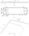
FIG. 1 is a perspective view of a plastic component from a perspective according to an embodiment of the present disclosure. -
FIG. 2 is a perspective view of a plastic component from another perspective according to an embodiment of the present disclosure. -
FIG. 3 is a top view of a plastic component according to an embodiment of the present disclosure. -
FIG. 4 is a cross-sectional view of A-A inFIG. 3 . -
FIG. 5 is a schematic view of a thickness of a body, a depth of a buffer recess, and a depth of a connection piece recess. -
FIG. 6 is a bottom view of a plastic component according to an embodiment of the present disclosure. -
FIG. 7 is a schematic view of a thinned groove of a plastic component according to an embodiment of the present disclosure. -
FIG. 8 is a bottom view of a plastic component according to another embodiment of the present disclosure. -
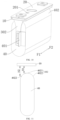
FIG. 9 is a perspective view of a connection piece. -
FIG. 10 is a schematic view of an assembly of a cover plate, a plastic component, a connection piece, and a bare cell. -
FIG. 11 is a schematic view of a relative position between a bare cell and a plastic component. -
plastic component 10,first side surface 1,buffer recess 11, flowguide hole 12,first side wall 13,second side wall 14,third side wall 15,fourth side wall 16,second side surface 2,connection piece recess 21, roundedcorner 211, positioning protrudingpost 212, thinned groove, outer peripheral groove wall 221, groovebottom wall 222, outerperipheral surface 3, pole throughhole 4,cover plate 20,liquid injection hole 201,connection piece 30,pole connection segment 301,tab connection segment 302,bare cell 40,tab 401,protrusion 402,proximal portion 4021,distal portion 4022. - Embodiments of the present disclosure will be described in detail below, and examples of the embodiments are shown in the accompanying drawings, in which identical or similar reference signs denote identical or similar elements or elements with identical or similar functions through the accompanying drawings. The following embodiments described with reference to the drawings are illustrative and intended to explain the present disclosure, rather than being interpreted as limitations on the present disclosure.
- In description of the present disclosure, it should be understood that orientations or positional relationships indicated by terms "longitudinal", "transverse", "length", "width", "thickness", "upper", "lower", "front", "rear", "left", "right", "vertical", "horizontal", "top", "bottom", "inner", "outer", and the like are based on orientations or positional relationships shown in the drawings, and facilitate the description of the present disclosure and simplify the description merely, rather than indicating or implying that the associated apparatus or element must have specific orientations and are constructed and operated in the specific orientations, and thus should not be construed to limit the present disclosure.
- In addition, the terms "first" and "second" are used only for description and shall not be interpreted as an indication or implication of relative importance or an implicit indication of the number of technical features. Thus, features associated with "first" and "second" may include at least one or more such features, either explicitly or implicitly. In the description of the present disclosure, "a plurality of" means two or more, unless otherwise specifically defined.
- In the present disclosure, unless otherwise specifically stated and defined, terms "mounted", "connect", "connect to", "fixed", and the like should be understood broadly. For example, it may be a fixed connection, detachable connection, or integrally formed; it may be a mechanical connection, an electric connection, or a communication; it may be a direct connection, an indirect connection through an intermediary, or a communication between the interiors of two elements or mutual acting relationship between the two elements. For those skilled in the art, the specific meaning of the above-mentioned terms in the embodiments of the present disclosure can be understood according to specific circumstances.
- A
plastic component 10 according to embodiments of the present disclosure will be described in detail with reference toFIG. 1 to FIG. 11 . Theplastic component 10 may be used in a battery. The battery includes a housing and a battery top cover. The housing has a receiving space, and the receiving space is provided with a battery cell. The battery top cover is used for sealing an opening of the receiving space. In some embodiments, theplastic component 10 may be formed as a part of the battery top cover. - Referring to
FIG. 1 to FIG. 6 , theplastic component 10 according to the embodiments of the present disclosure includes a body having afirst side surface 1 and asecond side surface 2 facing away from thefirst side surface 1. In some embodiments, with reference toFIG. 1 , an upper surface of the body is thefirst side surface 1, and a lower surface of the body is thesecond side surface 2. - The
first side surface 1 has abuffer recess 11, and thebuffer recess 11 is recessed towards thesecond side surface 2. As illustrated inFIG. 1 , thebuffer recess 11 is recessed downwards. Thebuffer recess 11 has at least oneflow guide hole 12, and theflow guide hole 12 penetrates the body in a thickness direction of the body. When theplastic component 10 is applied in the battery, an operation of injecting liquid into the battery may be completed through theflow guide hole 12. Thebuffer recess 11 is used as a buffer area of electrolyte, which may effectively prevent excessive liquid injection pressure from damaging a bare cell in a battery housing. Moreover, the internal pressure of the battery cell can be balanced. A recessed structure of thebuffer recess 11 also enhances a mechanical strength of a liquid injection area of the body to some extent. - In some embodiments of the present disclosure, one
flow guide hole 12 is provided, thereby facilitating simplification of processing process of theplastic component 10. Moreover, a liquid injection process is easy to manage when a number of the flow guide holes 12 is small. - In some embodiments of the present disclosure, a plurality of flow guide holes 12 is provided, thereby facilitating an improvement in liquid injection efficiency.
- The
second side surface 2 has aconnection piece recess 21, and theconnection piece recess 21 is recessed towards a direction where thefirst side surface 1 is located. When theplastic component 10 is applied in the battery, a connection piece may be at least partially installed and positioned in theconnection piece recess 21, thereby facilitating a reduction in an overall thickness of the connection piece after the connection piece is connected to theplastic component 10. In addition, a recessed structure of theconnection piece recess 21 strengthens a mechanical strength of a connection piece area of the body to some extent. - In some embodiments of the present disclosure, the
plastic component 10 satisfies at least one of condition 1: 1 mm≤c-e≤2 mm and 1 mm≤c-f≤2 mm, where c is a thickness of the body, f is a depth of thebuffer recess 11, e is a depth of theconnection piece recess 21; and condition 2: 1 mm≤p≤2 mm, p= (a-t*g-r*d) /n, where g represents a length of theconnection piece recess 21, t represents a number of the connection piece recesses 21, r represents a number of the buffer recesses 11, d represents a length of thebuffer recess 11, a represents a length of the body, and p represents a thickness of each of n side walls arranged in a length direction of the body. - For the
plastic component 10 according to the above embodiments, by defining thebuffer recess 11 at thefirst side surface 1 of the body and defining theconnection piece recess 21 at thesecond side surface 2, materials used in theplastic component 10 can be reduced and costs can be saved. Moreover, feasibility of injection molding may be guaranteed by satisfying the at least one of condition 1) and condition 2). - In some embodiments, the
plastic component 10 is generally manufactured by using injection molding process. The injection molding process has a poor molding effect on an injection molded part with a thickness greater than 2 mm. Moreover, the plastic component longitudinally occupies a large space, which may increase a weight of the battery, resulting in a reduced battery energy density. Conversely, in response that the thickness is less than 1 mm, a requirement for a strength of the injection molded part is not satisfied. - In condition 1), a range of 1 mm≤c-e≤2 mm indicates a distance between a bottom surface of the
connection piece recess 21 and thefirst side surface 1, i.e., a wall thickness of the body at theconnection piece recess 21. A range of 1 mm≤c-f≤2 mm represents a distance between a bottom surface of thebuffer recess 11 and thesecond side surface 2, i.e., a wall thickness of the body at thebuffer recess 11. On one hand, the feasibility of injection molding may be assured, and a structural strength of theplastic component 10 at the groove is ensured. On the other hand, it can ensure thebuffer recess 11 can withstand an impact force of the injected electrolyte and a weight of the accommodated electrolyte, and prevent thebuffer recess 11 from being bent and deformed when the battery is exposed to heat or vibration. - In the illustrated implementations, the
first side surface 1 has onebuffer recess 11, and thesecond side surface 2 has two connection piece recesses 21. The two connection piece recesses 21 are located at two ends of thebuffer recess 11 respectively, allowing t=2, r=1, and n=4. With reference toFIG. 4 , in the length direction of the body, four side walls are provided at a bottom of the plastic component 10: from left to right, they are respectively referred to as afirst side wall 13, asecond side wall 14, athird side wall 15, and afourth side wall 16, i.e., n=4. In condition 2), 1 mm≤p≤2 mm, which ensures feasibility of injection molding for each side wall and guarantees quality of the injection molding. In addition, a thickness of each side wall should satisfy an equation p=(a-2g-d)/4, which guarantees equal thickness for the four side walls. Moreover, a side wall thickness is in a range of 1 mm≤p≤2 mm, which may also ensure the structural strength of the plastic component during assembly or when subjected to vibration. Further, equal thickness among the side walls ensures uniform force distribution on each part of the plastic component and reduces deformation of the plastic component when subjected to force. It can be understood that, in other implementations, t, r, and n may also be other numerical values and may be determined as desired, which is not exemplarily limited herein. - The
first side wall 13 is a left side wall of a leftconnection piece recess 21. Thesecond side wall 14 is a right side wall of the leftconnection piece recess 21 and a left side wall of thebuffer recess 11. Thethird side wall 15 is a right side wall of thebuffer recess 11 and a left side wall of a rightconnection piece recess 21. Thefourth side wall 16 is a right side wall of the rightconnection piece recess 21. - Through condition 1) and condition 2), a wall thickness between adjacent structures is ensured to be controlled in a range of 1 mm to 2 mm. In a case where the feasibility of injection molding and structural strength are satisfied, a large amount of production materials are also saved.
- In some examples, c-e may be 1 mm, 1.1 mm, 1.2 mm, 1.5 mm, 1.7 mm, 1.9 mm, or 2 mm. Certainly, c-e may also be other numerical values between 1 mm and 2 mm, which are not listed here.
- In some examples, c-f may be 1 mm, 1.3 mm, 1.4 mm, 1.6 mm, 1.8 mm, or 2 mm. Certainly, c-e may also be other numerical values between 1 mm and 2 mm, which are not listed here.
- In some examples, c-e may be equal to c-f, greater than c-f, or less than c-f.
- In some examples, p may be 1 mm, 1.1 mm, 1.3 mm, 1.7 mm, 1.9 mm, or 2 mm. Certainly, p may also be other numerical values between 1 mm and 2 mm, which are not listed here.
- It can be understood that in other embodiments, the plastic component satisfies one of condition 1) and condition 2).
- Referring to
FIG. 1 to FIG. 6 , a pole throughhole 4 is defined in theconnection piece recess 21 and penetrates the body in the thickness direction of the body. The pole throughhole 4 is used for a pole to pass through, and the connection piece is welded and fixed to the pole. - In some embodiments of the present disclosure, referring to
FIG. 6 , the pole throughhole 4 is located at a center of the body in a width direction of the body, i.e., H1=H2. In this way, a structure of theplastic component 10 is an axisymmetric structure. When theplastic component 10 is installed in the battery, theplastic component 10 has no directivity. Moreover, even if theplastic component 10 is horizontally rotated by 180°, theplastic component 10 is still viable, thereby facilitating saving an assembly time. - In some embodiments of the present disclosure, referring to
FIG. 4 to FIG. 6 , n side walls include afirst side wall 13 and asecond side wall 14. Thefirst side wall 13 is a side wall of theconnection piece recess 21 away from thebuffer recess 11. Thesecond side wall 14 is a side wall of theconnection piece recess 21 close to thebuffer recess 11. A distance between the pole throughhole 4 and thefirst side wall 13 is greater than a distance between the pole throughhole 4 and thesecond side wall 14. It may be noted that "the distance between the pole throughhole 4 and thefirst side wall 13" refers to a distance between a center of the pole throughhole 4 and thefirst side wall 13, "the distance between the pole throughhole 4 and thesecond side wall 14" refers to a distance between the center of the pole throughhole 4 and thesecond side wall 14, and the distance between the center of the pole throughhole 4 and thefirst side wall 13 is greater than the distance between the center of the pole throughhole 4 and thesecond side wall 14, i.e., H3 >H4. In this way, the center of the pole throughhole 4 is far away from an edge of the body, which may reduce a hole cracking risk at the pole throughhole 4. - With the
plastic component 10 according to the embodiments of the present disclosure, thebuffer recess 11 is defined at thefirst side surface 1 of the body, so that the electrolyte may be buffered, and the bare cell in the battery housing may be prevented from being damaged due to excessive liquid injection pressure. Moreover, the material of the body may be decreased. By defining theconnection piece recess 21 at thesecond side surface 2, the overall thickness of the connection piece can be lowed after being connected to theplastic component 10 and further reduce the material of the body. Therefore, the material required for forming theplastic component 10 and the time required for injection molding cooling are saved, which greatly economizes on the cost. - In some embodiments of the present disclosure, projection areas of the
connection piece recess 21 and thebuffer recess 11 on the body are offset from each other. In this way, the thickness of the body is not excessively reduced, which helps keep the body high in strength. - According to some embodiments of the present disclosure, an offset between the projection area of the
connection piece recess 21 on the body and the projection area of thebuffer recess 11 on the body ranges from 1 mm to 2 mm. As illustrated inFIG. 5 , the offset between the projection area of theconnection piece recess 21 on the body and the projection area of thebuffer recess 11 on the body is p, i.e., the thickness of the side wall, and p is greater than or equal to 1 mm and less than or equal to 2 mm. When p is less than 1 mm, a connection strength between theconnection piece recess 21 and thebuffer recess 11 is small, and the body is easy to crack in an area between theconnection piece recess 21 and thebuffer recess 11; and when p is greater than 2 mm, it will result in significant fluctuations in the thickness of the body, consequently leading to an increased level of injection molding difficulty and a decreased success rate of injection molding. Exemplarily, p may be 1 mm, 1.1 mm, 1.3 mm, 1.7 mm, 1.9 mm, 2 mm, or the like. Certainly, p may also be other numerical values in the range of 1 mm and 2 mm. The enumeration of details shall be eschewed henceforth. - In some embodiments of the present disclosure, referring to
FIG. 2, FIG. 4 , andFIG. 6 , thesecond side surface 2 has two connection piece recesses 21, and thefirst side surface 1 has onebuffer recess 11. The two connection piece recesses 21 are located at each of two ends of thebuffer recess 11. In this way, the connection piece area is offset from a liquid injection buffer area, which is beneficial to reasonably utilizing the space. Moreover, the two connection piece recesses 21 facilitate a connection between theplastic component 10 and the two connection pieces respectively. The recessed structure of thebuffer recess 11 enhances a mechanical strength of a middle area of the body to some extent. Moreover, the recessed structure of theconnection piece recess 21 strengthens a mechanical strength of areas at the two ends of the body to some extent. - In some embodiments of the present disclosure, referring to
FIG. 2 andFIG. 7 , the body has a predetermined thickness. Thefirst side surface 1 is connected to thesecond side surface 2 through an outerperipheral surface 3, and thesecond side surface 2 has a thinnedgroove 22 having an outer peripheral groove wall 221 and agroove bottom wall 222. The outer peripheral groove wall 221 is separated from the outerperipheral surface 3, and theconnection piece recess 21 is defined in thegroove bottom wall 222. By defining the thinnedgroove 22, a mechanical strength of thesecond side surface 2 of the body may be enhanced to some extent. The thinnedgroove 22 may also be used as a hot melting area of a polyester film Mylar. In some embodiments, a top of the polyester film Mylar is disposed in the thinnedgroove 22, and a connection between the polyester film Mylar and the body is realized through hot melting process. - According to some embodiments of the present disclosure, referring to
FIG. 8 , theconnection piece recess 21 is provided with apositioning protruding post 212 protruding away from thefirst side surface 1. An end surface of thepositioning protruding post 212 is flush with thegroove bottom wall 222 of the thinnedgroove 22. Thepositioning protruding post 212 is offset from the pole throughhole 4 and may position the connection piece. For example, the connection piece has a positioning hole, and thepositioning protruding post 212 is inserted into the positioning hole. Therefore, positioning of the connection piece in theconnection piece recess 21 is realized, thereby facilitating welding and fixing of the connection piece and the pole in the pole throughhole 4. - In some embodiments of the present disclosure, the body is of a flat plate-like structure and has a length greater than or equal to 300 mm and a width greater than or equal to 100 mm. In this way, it can be guaranteed that the body is matched with the corresponding battery, preventing negative impact on normal use of the body due to its size being too small. Moreover, the thickness of the body is greater than or equal to 4 mm, which may ensure that the strength of the body is excessively reduced because the thickness of the body is too thin. In some embodiments, referring to
FIG. 3 to FIG. 5 , the length of the body is a, where a is greater than or equal to 300 mm, a width of the body is b, where b is greater than or equal to 107 mm, and the thickness of the body is c, where c is greater than or equal to 4 mm. Exemplarily, a may be 300 mm, 310 mm, 320 mm, 330 mm, 340 mm, etc., b may be 100 mm, 105 mm, 110 mm, 113 mm, 116 mm, 119 mm, etc., and c may be 4 mm, 6 mm, 8 mm, 10 mm, 12 mm, etc.. Of course, a, b, and c may also be other numerical values greater than their respective lower limit values, which are not exhaustively listed herein. - In some embodiments of the present disclosure, the thickness of the body is less than or equal to 30 mm, which may ensure that the body is thin, thus saving materials. The thin body is beneficial to improving injection molding efficiency of the
plastic component 10, as well as increasing a success rate of forming theplastic component 10. - In some embodiments of the present disclosure, the length of the
buffer recess 11 is greater than or equal to 285 mm, a width of thebuffer recess 11 is greater than or equal to 96 mm, and the depth of thebuffer recess 11 is greater than or equal to 2.5 mm. In this way, it can be ensured that thebuffer recess 11 is matched with the corresponding battery, with a great area and sufficient depth. Thebuffer recess 11 can well buffer the liquid during liquid injection, avoiding a case where a size of thebuffer recess 11 is too small and affects a buffer effect on the liquid during injection, such as liquid overflow. In some embodiments, referring toFIG. 3 to FIG. 5 , the length of thebuffer recess 11 is d, where d is greater than or equal to 285 mm. The width of thebuffer recess 11 is m, where m is greater than or equal to 96 mm. The depth of thebuffer recess 11 is f, and f is greater than or equal to 2.5 mm. Exemplarily, d may be 2 mm, 4 mm, 5 mm, 6 mm, 10 mm, etc., m may be 96 mm, 100 mm, 104 mm, 108 mm, 112 mm, 116 mm, etc., and f may be 2.5 mm, 2.7 mm, 2.9 mm, 3.1 mm, 3.3 mm, etc. Certainly, d, m, and f may also be other numerical values greater than their respective lower limit values, which will not be exhaustively listed here. - In some embodiments of the present disclosure, a dimension of the
connection piece recess 21 in the length direction of the body is greater than or equal to 50 mm, a dimension of theconnection piece recess 21 in a width direction of the body is greater than or equal to 86 mm, and the depth of theconnection piece recess 21 is greater than or equal to 2.5 mm. In this way, it can be ensured that theconnection piece recess 21 is matched with the corresponding battery, with the great area and sufficient depth, thereby lowering a connection difficulty when theconnection piece recess 21 is connected to the connection piece. In some embodiments, referring toFIG. 5 and FIG. 6 , the dimension of theconnection piece recess 21 in the length direction of the body is g, where g is greater than or equal to 50 mm. The dimension of theconnection piece recess 21 in the width direction of the body is q, where q is greater than or equal to 86 mm. The depth of theconnection piece recess 21 is e, and e is greater than or equal to 2.5 mm. Exemplarily, g may be 50 mm, 52 mm, 54 mm, 56 mm, 58 mm, and so on. Similarly, q may be 86 mm, 88 mm, 90 mm, 92 mm, 94 mm, and so forth. Likewise, e may be 2.5 mm, 2.7 mm, 2.9 mm, 3.0 mm, etc. Certainly, g, q, and e may also be other numerical values greater than their respective lower limit values, which will not be exhaustively listed here. - In some embodiments of the present disclosure, referring to
FIG. 6 , theconnection piece recess 21 has a roundedcorner 211 at a side of theconnection piece recess 21 close to the buffer recess. A fillet radius of therounded corner 211 ranges from 5 mm to 20 mm. A fillet size of therounded corner 211 matches an outer dimension of the connection piece, allowing therounded corner 211 to perform position restriction on the connection piece. In addition, compared with a right angle, the structure of therounded corner 211 may also alleviate a stress concentration phenomenon at the corner of theconnection piece recess 21, avoiding fracture of theplastic component 10. - In some embodiments of the present disclosure, the body may further have a liquid return hole penetrating the body in the thickness direction of the body, allowing the electrolyte at a top of the body to flow back through the liquid return hole when the battery is inverted.
- According to the embodiments in another aspect of the present disclosure, a battery includes the
plastic component 10 according to the above embodiments. - For the battery according to the embodiments of the present disclosure, by defining the
buffer recess 11 at thefirst side surface 1 of the body and defining theconnection piece recess 21 at thesecond side surface 2, the materials in theplastic component 10 can be reduced and the costs can be saved. Moreover, the feasibility of injection molding may be ensured by satisfying the at least one of condition 1) and condition 2). - In some embodiments of the present disclosure, as illustrated in
FIG. 1, FIG. 2 , andFIG. 10 , the battery further includes acover plate 20. Thecover plate 20 is located at a side of afirst side surface 1 of theplastic component 10 and has aliquid injection hole 201. A projection of theliquid injection hole 201 on thefirst side surface 1 is located in abuffer recess 11, and aflow guide hole 12 is offset from theliquid injection hole 201. In this way, after the electrolyte enters thebuffer recess 11 from theliquid injection hole 201, the electrolyte may be fully buffered in thebuffer recess 11, and then enter the battery from theflow guide hole 12, thereby reducing an impact force of the electrolyte on an interior of the battery and allowing the liquid injection process to be more stable. As illustrated inFIG. 1 to FIG. 3 andFIG. 6 , theflow guide hole 12 is located in thebuffer recess 11 and is close to aconnection piece recess 21 at a right end. Certainly, in some embodiments not illustrated in the drawings, theflow guide hole 12 may be located in thebuffer recess 11 and close to aconnection piece recess 21 at a left end, or theflow guide hole 12 may be located at a center position of thebuffer recess 11. - In some embodiments of the present disclosure, as illustrated in
FIG. 1 and FIG. 2 ,FIG. 9 andFIG. 10 , the battery further includes aconnection piece 30 and a pole. The pole passes through the pole throughhole 4. Theconnection piece 30 is located at a side of asecond side 2 of theplastic component 10 and includes apole connection segment 301 and atab connection segment 302. Thepole connection segment 301 is directly connected to thetab connection segment 302, or thepole connection segment 301 is indirectly connected to thetab connection segment 302 through a middle connection segment. Thepole connection segment 301 is located in aconnection piece recess 21 and fixedly connected to the pole. Thetab connection segment 302 extends away from theplastic component 10, and an angle between thetab connection segment 302 and thepole connection segment 301 is in a range of 70° to 110°. Thetab connection segment 302 is adapted to be connected to other parts of the battery (for example, thetab 401 of thebare cell 40 mentioned below), and thetab connection segment 302 and thepole connection segment 301 are located in different planes, which facilitates an arrangement of thetab connection segment 302 at a position convenient for a connection operation, and decreases a lateral size of the battery (i.e., a size of the battery in a F1-F2 direction). Exemplarily, the angle between thetab connection segment 302 and thepole connection segment 301 is 90°, i.e., thetab connection segment 302 is perpendicular to thepole connection segment 301. - In some embodiments of the present disclosure, as illustrated in
FIG. 1 and FIG. 2 ,FIG. 9 andFIG. 10 , the battery further includes at least onebare cell 40 provided at a side of thepole connection segment 301 facing away from theplastic component 10. A longitudinal extending direction of thebare cell 40 is consistent with a length direction of a body. A longitudinal end portion of thebare cell 40 is atab 401, and thetab 401 is connected to thetab connection segment 302. The length direction of the body is the F1-F2 direction illustrated inFIG. 10 , and the longitudinal extending direction of thebare cell 40 is consistent with the length direction of the body, allowing a distance between a plane area of sidewall surface of thebare cell 40 and theflow guide hole 12 on the body to be small. In this way, when the electrolyte enters the battery through theflow guide hole 12, the electrolyte may be in contact with the plane area of sidewall surface of thebare cell 40 more effectively and quickly, thus facilitating faster soak of thebare cell 40 and shortening the idle time. In addition, thetab 401 is located at a side surface, which is convenient for a connection between thetab 401 and thetab connection segment 302. -
FIG. 11 is a schematic diagram of a relative position of abare cell 40 and aplastic component 10 in a cross-section perpendicular to the F1-F2 direction inFIG. 10 . In some embodiments of the present disclosure, as illustrated inFIG. 1 and FIG. 2 ,FIG. 10 and FIG. 11 , thebare cell 40 has aprotrusion 402 protruding towards theplastic component 10. Theprotrusion 402 includes aproximal portion 4021 and adistal portion 4022, and theproximal portion 4021 is closest to theplastic component 10. A distance between thedistal portion 4022 and theplastic component 10 is greater than the distance between theproximal portion 4021 and theplastic component 10. As illustrated inFIG. 11 , the distance between theproximal portion 4021 and theplastic component 10 is H1, the distance between thedistal portion 4022 and theplastic component 10 is H2, and H2>H1. Theproximal portion 4021 is the nearest position of thebare cell 40 from theplastic component 10, which is the highest point of thebare cell 40. A predetermined space is defined between theprotrusion 402 and theplastic component 10, which may reduce obstruction of the electrolyte when passing through the space, and facilitate downward flow and diffusion of the electrolyte. - In an example, an outer surface of the
protrusion 402 may be constructed as a semicylindrical surface, such that theproximal portion 4021 is a generating line of the semicylindrical surface. - In some embodiments, the projection of the
flow guide hole 12 on theprotrusion 402 is located at thedistal portion 4022. In this way, when the electrolyte enters the interior of the battery through theflow guide hole 12, the electrolyte directly drops on thedistal portion 4022 instead of theproximal portion 4021, and thedistal portion 4022 can guide the electrolyte faster to a side surface space of thebare cell 40. - Alternatively, in other embodiments, the
flow guide hole 12 is offset from theprotrusion 402, i.e., theflow guide hole 12 directly faces towards the side surface space of thebare cell 40, and the electrolyte may directly enter the side surface space of thebare cell 40 through theflow guide hole 12. - In some embodiments of the present disclosure, the
buffer recess 11 internally has a plurality of flow guide holes 12 penetrating the body in a thickness direction of the body. Each of two sides of theproximal portion 4021 has the plurality of flow guide holes 12. The plurality of flow guide holes 12 may disperse the electrolyte, thereby reducing the impact force on thebare cell 40 and improving the liquid injection efficiency of the battery. In addition, a soaking speed of the electrolyte on thebare cell 40 is enhanced, and the idle time is reduced. - In an example, two flow guide holes 12 are provided and disposed on the
distal portions 4022 at two sides of theproximal portion 4021, respectively. Alternatively, in another example, the two flow guide holes 12 may be provided and disposed at two sides of thebare cell 40, respectively. - In other embodiments of the present disclosure, one
flow guide hole 12 is provided. - In some embodiments of the present disclosure, the battery includes a plurality of
bare cells 40. Aflow guide hole 12 is located at a center line between two adjacentbare cells 40. In this way, a space below theflow guide hole 12 is great, and the obstruction to the electrolyte may be decreased. - A battery module according to the embodiments in another aspect of the present disclosure includes the battery according to any one of the above embodiments.
- For the battery module according to the embodiments of the present disclosure, the
buffer recess 11 is defined at thefirst side surface 1 of the body, and theconnection piece recess 21 is defined at thesecond side surface 2 of the body, which may reduce the materials used in theplastic component 10 and save the costs. Moreover, the feasibility of injection molding may be ensured by satisfying the at least one of condition 1) and condition 2). - In some embodiments, one battery module may include one or more batteries. The plurality of batteries is electrically connected to each other in a series, parallel, or series-parallel manner. The term plurality may refer to two or more.
- An electric device according to another embodiment of the present disclosure includes the battery module according to the above embodiments.
- For the electric device according to the embodiments of the present disclosure, by defining the
buffer recess 11 at thefirst side surface 1 of the body and theconnection piece recess 21 at thesecond side surface 2, the materials in theplastic component 10 can be reduced and the costs can be saved. Moreover, the feasibility of injection molding may be ensured by satisfying the at least one of condition 1) and condition 2). - In some embodiments, the electric device may include one or more battery modules. The plurality of battery modules may be electrically connected to each other in series, parallel, or series-parallel connection.
- An electric device includes, but is not limited to, an energy storage device and a vehicle. The energy storage device may be an energy storage container. The energy storage container includes a box body and a battery cluster disposed in the box body. The battery cluster includes a cluster frame and a plurality of battery packs, and the plurality of battery modules is installed on the cluster frame. The energy storage device may also be a household energy storage cabinet.
- The battery module may be applied in the vehicle as a power battery pack. The Vehicle includes, but is not limited to, a pure electric vehicle, a hybrid vehicle, an extended-range electric vehicles, and the like.
- In descriptions of this specification, descriptions in the reference terms "an embodiment", "some embodiments", "example", "specific example", "some examples" or the like mean that the specific features, structures, materials or characteristics described in combination with the embodiments or the examples are included in at least one embodiment or example of the present disclosure. In the present specification, the schematic representation of the above terms does not necessarily mean the same embodiment or example. Moreover, the described specific features, structures, materials or characteristics may be combined in any one or more embodiments or examples in a suitable mode. In addition, various embodiments or examples described in the specification, as well as features of various embodiments or examples, may be combined by those skilled in the art.
- Although the embodiments of the present disclosure have been shown and described above, it can be understood that the above-mentioned embodiments are exemplary and should not be construed as limiting the present disclosure. Those of ordinary skill in the art can make changes, modifications, substitutions and modifications to the above-mentioned embodiments within the scope of the present disclosure.
Claims (21)
- A plastic component, comprising a body having a first side surface (1) and a second side surface (2) facing away from the first side surface (1), the first side surface (1) having a buffer recess (11) recessed towards the second side surface (2), the buffer recess (11) having at least one flow guide hole (12) penetrating the body in a thickness direction of the body, the second side surface (2) having at least one connection pieces recess (21) recessed towards the first side surface (1), each of the at least one connection piece recess (21) having a pole through hole (4) penetrating the body in the thickness direction of the body, and the plastic component satisfying at least one of:condition 1): 1 mm≤c-e≤2 mm and 1 mm≤c-f≤2 mm, where c represents a thickness of the body, f represents a depth of the buffer recess (11), e represents a depth of the connection piece recess (21); andcondition 2): 1 mm≤p≤2 mm, p= (a-t*g-r*d) /n, where g represents a length of the connection piece recess (21), t represents a number of the connection piece recesses (21), r represents a number of the buffer recesses (11), d represents a length of the buffer recess (11), a represents a length of the body, and p represents a thickness of each of n side walls arranged in a length direction of the body.
- The plastic component according to claim 1, wherein a projection region of the connection piece recess (21) on the body and a projection region of the buffer recess (11) on the body are offset from each other.
- The plastic component according to claim 1 or 2, wherein the at least one connection piece recess (21) comprises two connection piece recesses (21), and the first side surface (1) has one buffer recess (11), the two connection piece recesses (21) being located at two ends of the buffer recess (11) respectively, where t=2, r=1, and n=4.
- The plastic component according to any one of claims 1 to 3, wherein:the first side surface (1) is connected to the second side surface (2) through an outer peripheral surface (3); andthe second side surface (2) has a thinned groove (22) having an outer peripheral groove wall (221) and a groove bottom wall (222), the outer peripheral groove wall (221) being separated from the outer peripheral surface (3), and the connection piece recess (21) being formed at the groove bottom wall (222).
- The plastic component according to claim 4, wherein the connection piece recess (21) is provided with a positioning protruding post (212) protruding away from the first side surface (1), the positioning protruding post (212) having an end surface flush with the groove bottom wall (222) of the thinned groove (22).
- The plastic component according to any one of claims 1 to 5, wherein the body is of a flat plate-like structure, and has a length greater than or equal to 300 mm, a width greater than or equal to 100 mm, and a thickness greater than or equal to 4 mm.
- The plastic component according to claim 6, wherein the thickness of the body is less than or equal to 30 mm.
- The plastic component according to any one of claims 1 to 7, wherein the length of the buffer recess (11) is greater than or equal to 285 mm, a width of the buffer recess (11) is greater than or equal to 96 mm, and the depth of the buffer recess (11) is greater than or equal to 2.5 mm.
- The plastic component according to any one of claims 1 to 8, wherein:a dimension of the connection piece recess (21) in a length direction of the body is greater than or equal to 50 mm;a dimension of the connection piece recess (21) in a width direction of the body is greater than or equal to 86 mm; anda depth of the connection piece recess (21) is greater than or equal to 2.5 mm.
- The plastic component according to any one of claims 1 to 9, wherein the connection piece recess (21) has a rounded corner (211) at a side of the connection piece recess (21) close to the buffer recess (11), a fillet radius of the rounded corner (211) ranging from 5 mm to 20 mm.
- The plastic component according to any one of claims 1 to 10, wherein the pole through hole (4) is located at a center of the body in a width direction of the body.
- The plastic component according to any one of claims 1 to 11, wherein the n side walls comprise a first side wall (13) and a second side wall (14), the first side wall (13) being a side wall of the connection piece recess (21) away from the buffer recess (11), the second side wall (14) being a side wall of the connection piece recess (21) close to the buffer recess (11), a distance between the pole through hole (4) and the first side wall (13) being greater than a distance between the pole through hole (4) and the second side wall (14).
- A battery, comprising the plastic component according to any one of claims 1 to 12.
- The battery according to claim 13, further comprising a cover plate (20) located at a side of the first side surface (1) of the plastic component and having a liquid injection hole (201), a projection of the liquid injection hole (201) on the first side surface (1) being located at the buffer recess (11), and the at least one flow guide hole (12) being offset from the liquid injection hole (201).
- The battery according to claim 13 or 14, further comprising a connection piece (30) and a pole, the pole passing through the pole through hole (4), the connection sheet (30) being located at a side of the second side surface (2) of the plastic component and comprising a pole connection segment (301) and a tab connection segment (302) connected to the pole connection segment (301), the pole connection segment (301) being located at the connection piece recess (21) and fixedly connected to the pole, the tab connection segment (302) extending away from the plastic component, and an angle between the tab connection segment (302) and the pole connection segment (301) being greater than 70° and less than 110°.
- The battery according to claim 15, further comprising at least one bare cell (40) arranged at a side of the pole connection segment (301) facing away from the plastic component, a longitudinal extending direction of the at least one bare cell (40) being consistent with a length direction of the body, and a longitudinal end of the at least one bare cell (40) being a tab (401) connected to the tab connection segment (302).
- The battery according to claim 16, wherein the at least one bare cell (40) has a protrusion (402) protruding towards the plastic component, the protrusion (402) comprising a proximal portion and a distal portion, the proximal portion being closest to the plastic component, a distance between the distal portion and the plastic component being greater than a distance between the proximal portion and the plastic component, and a projection of the flow guide hole (12) on the protrusion (402) being located at the distal portion, or the flow guide hole (12) being offset from the protrusion (402).
- The battery according to claim 17, wherein the buffer recess (11) internally has a plurality of flow guide holes (12) penetrating the body in a thickness direction of the body and being formed at two sides of the proximal portion.
- The battery according to any one of claims 16 to 18, wherein the at least one bare cell (40) comprises a plurality of bare cells (40), the flow guide hole (12) being located at a center line between two adjacent bare cells (40).
- A battery module, comprising the battery according to any one of claims 13 to 19.
- An electric device, comprising the battery module according to claim 20.
Applications Claiming Priority (2)
| Application Number | Priority Date | Filing Date | Title |
|---|---|---|---|
| CN202211185639.2A CN117832780A (en) | 2022-09-27 | 2022-09-27 | Plastics, batteries, battery modules and electrical equipment |
| PCT/CN2022/143209 WO2024066107A1 (en) | 2022-09-27 | 2022-12-29 | Lower plastic, battery, battery module and electric device |
Publications (2)
| Publication Number | Publication Date |
|---|---|
| EP4379948A1 true EP4379948A1 (en) | 2024-06-05 |
| EP4379948A4 EP4379948A4 (en) | 2025-06-04 |
Family
ID=89573406
Family Applications (1)
| Application Number | Title | Priority Date | Filing Date |
|---|---|---|---|
| EP22944043.3A Pending EP4379948A4 (en) | 2022-09-27 | 2022-12-29 | LOWER PLASTIC, BATTERY, BATTERY MODULE AND ELECTRICAL DEVICE |
Country Status (5)
| Country | Link |
|---|---|
| US (1) | US20240128558A1 (en) |
| EP (1) | EP4379948A4 (en) |
| JP (1) | JP7770430B2 (en) |
| CN (1) | CN117832780A (en) |
| WO (1) | WO2024066107A1 (en) |
Family Cites Families (14)
| Publication number | Priority date | Publication date | Assignee | Title |
|---|---|---|---|---|
| KR100579391B1 (en) * | 2004-03-03 | 2006-05-12 | 삼성에스디아이 주식회사 | Can type secondary battery |
| JP5114063B2 (en) * | 2007-02-02 | 2013-01-09 | Necエナジーデバイス株式会社 | Sealed battery |
| JP5418809B2 (en) | 2008-10-16 | 2014-02-19 | 株式会社Gsユアサ | Battery and manufacturing method thereof |
| JP2011204469A (en) * | 2010-03-25 | 2011-10-13 | Sanyo Electric Co Ltd | Square sealed secondary battery |
| EP2613377B1 (en) | 2010-08-30 | 2019-01-09 | Eliiy Power Co., Ltd. | Battery cover with attached electrode terminal, method for producing battery cover with attached electrode terminal, and airtight battery |
| CN209401756U (en) * | 2018-12-29 | 2019-09-17 | 宁德时代新能源科技股份有限公司 | Secondary batteries and battery modules |
| CN209401664U (en) * | 2018-12-29 | 2019-09-17 | 宁德时代新能源科技股份有限公司 | Secondary batteries and battery modules |
| CN212366148U (en) * | 2020-05-14 | 2021-01-15 | 东莞塔菲尔新能源科技有限公司 | Plastic structure and battery under battery top cap |
| CN114512748A (en) * | 2020-10-26 | 2022-05-17 | 昆山聚创新能源科技有限公司 | Full utmost point ear top cap subassembly and full utmost point ear battery |
| CN114497836A (en) | 2020-10-26 | 2022-05-13 | 昆山聚创新能源科技有限公司 | Full utmost point ear top cap subassembly and full utmost point ear battery |
| CN214153028U (en) * | 2020-12-31 | 2021-09-07 | 蜂巢能源科技有限公司 | Top cap subassembly, electricity core, battery and vehicle |
| CN217009361U (en) * | 2022-03-03 | 2022-07-19 | 厦门海辰新能源科技有限公司 | Lower plastic component, battery top cover, battery and energy storage equipment |
| CN217134507U (en) * | 2022-06-07 | 2022-08-05 | 宁德时代新能源科技股份有限公司 | Battery cells, batteries and electrical devices |
| CN115036652A (en) * | 2022-07-01 | 2022-09-09 | 宁波震裕汽车部件有限公司 | Pole riveting connection method, pole connection structure and battery top cover |
-
2022
- 2022-09-27 CN CN202211185639.2A patent/CN117832780A/en active Pending
- 2022-12-29 EP EP22944043.3A patent/EP4379948A4/en active Pending
- 2022-12-29 WO PCT/CN2022/143209 patent/WO2024066107A1/en not_active Ceased
- 2022-12-29 JP JP2023576015A patent/JP7770430B2/en active Active
-
2023
- 2023-12-08 US US18/533,184 patent/US20240128558A1/en active Pending
Also Published As
| Publication number | Publication date |
|---|---|
| JP2024541785A (en) | 2024-11-13 |
| EP4379948A4 (en) | 2025-06-04 |
| CN117832780A (en) | 2024-04-05 |
| WO2024066107A1 (en) | 2024-04-04 |
| US20240128558A1 (en) | 2024-04-18 |
| JP7770430B2 (en) | 2025-11-14 |
Similar Documents
| Publication | Publication Date | Title |
|---|---|---|
| EP3699976B1 (en) | Battery pack provided with degassing flow channel | |
| EP3062361B1 (en) | Frame for secondary battery and battery module comprising same | |
| EP4435946A1 (en) | Battery box body, battery, electrical device, and manufacturing apparatus | |
| US20190006645A1 (en) | Battery module | |
| KR20240001222A (en) | Batteries and Electronics | |
| US20240405330A1 (en) | End cover assembly, battery cell, battery module, and energy storage device | |
| KR102693863B1 (en) | Battery Pack With Improved Vibration Resistance | |
| EP4203159A2 (en) | Battery module, battery pack including same, and vehicle | |
| KR100993127B1 (en) | Medium and large battery packs with excellent cooling efficiency | |
| US20240154207A1 (en) | Battery module | |
| CN116937050A (en) | Battery case assembly for electric vehicles | |
| CN105765754A (en) | Stirring elements, integrated series of stirring elements and accumulators | |
| US20130202925A1 (en) | Liquid electrolyte battery with mixing device | |
| EP4379948A1 (en) | Lower plastic, battery, battery module and electric device | |
| JP7674048B2 (en) | Battery pack and automobile including same | |
| US20250260133A1 (en) | Isolating plate assembly, battery module, battery pack, and electrical device | |
| EP4376178B1 (en) | Bottom plastic and battery having same | |
| EP4435955A1 (en) | Battery pack | |
| JP5066870B2 (en) | tray | |
| WO2022159749A1 (en) | Battery housing and battery module including the battery housing | |
| KR20220021866A (en) | Battery module | |
| EP4576366A1 (en) | Battery pack and vehicle including same | |
| US12476303B2 (en) | Battery pack | |
| KR20200104621A (en) | Catridge for battery cell having counterbar hole and battery module assembly including the same | |
| US20260066424A1 (en) | Traction battery pack thermal barrier |
Legal Events
| Date | Code | Title | Description |
|---|---|---|---|
| STAA | Information on the status of an ep patent application or granted ep patent |
Free format text: STATUS: UNKNOWN |
|
| STAA | Information on the status of an ep patent application or granted ep patent |
Free format text: STATUS: THE INTERNATIONAL PUBLICATION HAS BEEN MADE |
|
| PUAI | Public reference made under article 153(3) epc to a published international application that has entered the european phase |
Free format text: ORIGINAL CODE: 0009012 |
|
| STAA | Information on the status of an ep patent application or granted ep patent |
Free format text: STATUS: REQUEST FOR EXAMINATION WAS MADE |
|
| 17P | Request for examination filed |
Effective date: 20231207 |
|
| AK | Designated contracting states |
Kind code of ref document: A1 Designated state(s): AL AT BE BG CH CY CZ DE DK EE ES FI FR GB GR HR HU IE IS IT LI LT LU LV MC ME MK MT NL NO PL PT RO RS SE SI SK SM TR |
|
| RAP1 | Party data changed (applicant data changed or rights of an application transferred) |
Owner name: HITHIUM TECH HK LIMITED |
|
| REG | Reference to a national code |
Ref country code: DE Ref legal event code: R079 Free format text: PREVIOUS MAIN CLASS: H01M0050593000 Ipc: H01M0050150000 |
|
| A4 | Supplementary search report drawn up and despatched |
Effective date: 20250507 |
|
| RIC1 | Information provided on ipc code assigned before grant |
Ipc: H01M 50/157 20210101ALI20250429BHEP Ipc: H01M 50/627 20210101ALI20250429BHEP Ipc: H01M 50/533 20210101ALI20250429BHEP Ipc: H01M 50/593 20210101ALI20250429BHEP Ipc: H01M 50/103 20210101ALI20250429BHEP Ipc: H01M 50/15 20210101AFI20250429BHEP |
|
| DAV | Request for validation of the european patent (deleted) | ||
| DAX | Request for extension of the european patent (deleted) | ||
| GRAP | Despatch of communication of intention to grant a patent |
Free format text: ORIGINAL CODE: EPIDOSNIGR1 |
|
| STAA | Information on the status of an ep patent application or granted ep patent |
Free format text: STATUS: GRANT OF PATENT IS INTENDED |
|
| INTG | Intention to grant announced |
Effective date: 20260127 |
|
| GRAS | Grant fee paid |
Free format text: ORIGINAL CODE: EPIDOSNIGR3 |
|
| GRAA | (expected) grant |
Free format text: ORIGINAL CODE: 0009210 |
|
| STAA | Information on the status of an ep patent application or granted ep patent |
Free format text: STATUS: THE PATENT HAS BEEN GRANTED |