EP4379932A1 - Battery pack and device including same - Google Patents
Battery pack and device including same Download PDFInfo
- Publication number
- EP4379932A1 EP4379932A1 EP22890267.2A EP22890267A EP4379932A1 EP 4379932 A1 EP4379932 A1 EP 4379932A1 EP 22890267 A EP22890267 A EP 22890267A EP 4379932 A1 EP4379932 A1 EP 4379932A1
- Authority
- EP
- European Patent Office
- Prior art keywords
- battery
- battery module
- venting
- frame
- flow path
- Prior art date
- Legal status (The legal status is an assumption and is not a legal conclusion. Google has not performed a legal analysis and makes no representation as to the accuracy of the status listed.)
- Pending
Links
- 238000013022 venting Methods 0.000 claims abstract description 70
- 238000007599 discharging Methods 0.000 claims abstract description 5
- 239000007789 gas Substances 0.000 description 23
- 239000002245 particle Substances 0.000 description 16
- 230000000694 effects Effects 0.000 description 6
- 238000004880 explosion Methods 0.000 description 4
- 230000005484 gravity Effects 0.000 description 4
- 229910052751 metal Inorganic materials 0.000 description 4
- 239000002184 metal Substances 0.000 description 4
- BASFCYQUMIYNBI-UHFFFAOYSA-N platinum Chemical compound [Pt] BASFCYQUMIYNBI-UHFFFAOYSA-N 0.000 description 4
- PXHVJJICTQNCMI-UHFFFAOYSA-N Nickel Chemical compound [Ni] PXHVJJICTQNCMI-UHFFFAOYSA-N 0.000 description 3
- 229910052782 aluminium Inorganic materials 0.000 description 3
- 230000008901 benefit Effects 0.000 description 3
- 229910052802 copper Inorganic materials 0.000 description 3
- 239000010949 copper Substances 0.000 description 3
- 229910052744 lithium Inorganic materials 0.000 description 3
- 239000000463 material Substances 0.000 description 3
- RYGMFSIKBFXOCR-UHFFFAOYSA-N Copper Chemical compound [Cu] RYGMFSIKBFXOCR-UHFFFAOYSA-N 0.000 description 2
- WHXSMMKQMYFTQS-UHFFFAOYSA-N Lithium Chemical compound [Li] WHXSMMKQMYFTQS-UHFFFAOYSA-N 0.000 description 2
- BQCADISMDOOEFD-UHFFFAOYSA-N Silver Chemical compound [Ag] BQCADISMDOOEFD-UHFFFAOYSA-N 0.000 description 2
- 239000000956 alloy Substances 0.000 description 2
- 229910045601 alloy Inorganic materials 0.000 description 2
- XAGFODPZIPBFFR-UHFFFAOYSA-N aluminium Chemical compound [Al] XAGFODPZIPBFFR-UHFFFAOYSA-N 0.000 description 2
- QVGXLLKOCUKJST-UHFFFAOYSA-N atomic oxygen Chemical compound [O] QVGXLLKOCUKJST-UHFFFAOYSA-N 0.000 description 2
- 239000011248 coating agent Substances 0.000 description 2
- 238000000576 coating method Methods 0.000 description 2
- 238000013461 design Methods 0.000 description 2
- 238000011161 development Methods 0.000 description 2
- 238000010586 diagram Methods 0.000 description 2
- PCHJSUWPFVWCPO-UHFFFAOYSA-N gold Chemical compound [Au] PCHJSUWPFVWCPO-UHFFFAOYSA-N 0.000 description 2
- 229910052737 gold Inorganic materials 0.000 description 2
- 239000010931 gold Substances 0.000 description 2
- 229910052759 nickel Inorganic materials 0.000 description 2
- 239000001301 oxygen Substances 0.000 description 2
- 229910052760 oxygen Inorganic materials 0.000 description 2
- 229910052697 platinum Inorganic materials 0.000 description 2
- 229910052709 silver Inorganic materials 0.000 description 2
- 239000004332 silver Substances 0.000 description 2
- UFHFLCQGNIYNRP-UHFFFAOYSA-N Hydrogen Chemical compound [H][H] UFHFLCQGNIYNRP-UHFFFAOYSA-N 0.000 description 1
- 238000003915 air pollution Methods 0.000 description 1
- OJIJEKBXJYRIBZ-UHFFFAOYSA-N cadmium nickel Chemical compound [Ni].[Cd] OJIJEKBXJYRIBZ-UHFFFAOYSA-N 0.000 description 1
- 229910052799 carbon Inorganic materials 0.000 description 1
- 238000001816 cooling Methods 0.000 description 1
- 238000010292 electrical insulation Methods 0.000 description 1
- 238000005516 engineering process Methods 0.000 description 1
- 239000002803 fossil fuel Substances 0.000 description 1
- 230000017525 heat dissipation Effects 0.000 description 1
- 239000001257 hydrogen Substances 0.000 description 1
- 229910052739 hydrogen Inorganic materials 0.000 description 1
- 238000009413 insulation Methods 0.000 description 1
- 238000000034 method Methods 0.000 description 1
- 238000012986 modification Methods 0.000 description 1
- 230000004048 modification Effects 0.000 description 1
- QELJHCBNGDEXLD-UHFFFAOYSA-N nickel zinc Chemical compound [Ni].[Zn] QELJHCBNGDEXLD-UHFFFAOYSA-N 0.000 description 1
- 230000001151 other effect Effects 0.000 description 1
- 230000000644 propagated effect Effects 0.000 description 1
- 238000007789 sealing Methods 0.000 description 1
- 238000000926 separation method Methods 0.000 description 1
Images


Classifications
-
- H—ELECTRICITY
- H01—ELECTRIC ELEMENTS
- H01M—PROCESSES OR MEANS, e.g. BATTERIES, FOR THE DIRECT CONVERSION OF CHEMICAL ENERGY INTO ELECTRICAL ENERGY
- H01M50/00—Constructional details or processes of manufacture of the non-active parts of electrochemical cells other than fuel cells, e.g. hybrid cells
- H01M50/30—Arrangements for facilitating escape of gases
- H01M50/394—Gas-pervious parts or elements
-
- H—ELECTRICITY
- H01—ELECTRIC ELEMENTS
- H01M—PROCESSES OR MEANS, e.g. BATTERIES, FOR THE DIRECT CONVERSION OF CHEMICAL ENERGY INTO ELECTRICAL ENERGY
- H01M50/00—Constructional details or processes of manufacture of the non-active parts of electrochemical cells other than fuel cells, e.g. hybrid cells
- H01M50/20—Mountings; Secondary casings or frames; Racks, modules or packs; Suspension devices; Shock absorbers; Transport or carrying devices; Holders
- H01M50/204—Racks, modules or packs for multiple batteries or multiple cells
- H01M50/207—Racks, modules or packs for multiple batteries or multiple cells characterised by their shape
- H01M50/209—Racks, modules or packs for multiple batteries or multiple cells characterised by their shape adapted for prismatic or rectangular cells
-
- H—ELECTRICITY
- H01—ELECTRIC ELEMENTS
- H01M—PROCESSES OR MEANS, e.g. BATTERIES, FOR THE DIRECT CONVERSION OF CHEMICAL ENERGY INTO ELECTRICAL ENERGY
- H01M50/00—Constructional details or processes of manufacture of the non-active parts of electrochemical cells other than fuel cells, e.g. hybrid cells
- H01M50/20—Mountings; Secondary casings or frames; Racks, modules or packs; Suspension devices; Shock absorbers; Transport or carrying devices; Holders
- H01M50/204—Racks, modules or packs for multiple batteries or multiple cells
- H01M50/207—Racks, modules or packs for multiple batteries or multiple cells characterised by their shape
- H01M50/211—Racks, modules or packs for multiple batteries or multiple cells characterised by their shape adapted for pouch cells
-
- H—ELECTRICITY
- H01—ELECTRIC ELEMENTS
- H01M—PROCESSES OR MEANS, e.g. BATTERIES, FOR THE DIRECT CONVERSION OF CHEMICAL ENERGY INTO ELECTRICAL ENERGY
- H01M50/00—Constructional details or processes of manufacture of the non-active parts of electrochemical cells other than fuel cells, e.g. hybrid cells
- H01M50/30—Arrangements for facilitating escape of gases
- H01M50/342—Non-re-sealable arrangements
- H01M50/3425—Non-re-sealable arrangements in the form of rupturable membranes or weakened parts, e.g. pierced with the aid of a sharp member
-
- H—ELECTRICITY
- H01—ELECTRIC ELEMENTS
- H01M—PROCESSES OR MEANS, e.g. BATTERIES, FOR THE DIRECT CONVERSION OF CHEMICAL ENERGY INTO ELECTRICAL ENERGY
- H01M50/00—Constructional details or processes of manufacture of the non-active parts of electrochemical cells other than fuel cells, e.g. hybrid cells
- H01M50/30—Arrangements for facilitating escape of gases
- H01M50/35—Gas exhaust passages comprising elongated, tortuous or labyrinth-shaped exhaust passages
- H01M50/358—External gas exhaust passages located on the battery cover or case
-
- H—ELECTRICITY
- H01—ELECTRIC ELEMENTS
- H01M—PROCESSES OR MEANS, e.g. BATTERIES, FOR THE DIRECT CONVERSION OF CHEMICAL ENERGY INTO ELECTRICAL ENERGY
- H01M2200/00—Safety devices for primary or secondary batteries
- H01M2200/20—Pressure-sensitive devices
-
- Y—GENERAL TAGGING OF NEW TECHNOLOGICAL DEVELOPMENTS; GENERAL TAGGING OF CROSS-SECTIONAL TECHNOLOGIES SPANNING OVER SEVERAL SECTIONS OF THE IPC; TECHNICAL SUBJECTS COVERED BY FORMER USPC CROSS-REFERENCE ART COLLECTIONS [XRACs] AND DIGESTS
- Y02—TECHNOLOGIES OR APPLICATIONS FOR MITIGATION OR ADAPTATION AGAINST CLIMATE CHANGE
- Y02E—REDUCTION OF GREENHOUSE GAS [GHG] EMISSIONS, RELATED TO ENERGY GENERATION, TRANSMISSION OR DISTRIBUTION
- Y02E60/00—Enabling technologies; Technologies with a potential or indirect contribution to GHG emissions mitigation
- Y02E60/10—Energy storage using batteries
Definitions
- the present disclosure relates to a battery pack and a device including the same, and more particularly, to a battery pack that can prevent external ignition phenomena, and a device including the same.
- chargeable/dischargeable secondary batteries are used as a power source for an electric vehicle (EV), a hybrid electric vehicle (HEV), a plug-in hybrid electric vehicle (P-HEV) and the like, in an attempt to solve air pollution and the like caused by existing gasoline vehicles using fossil fuel. Therefore, the demand for development of the secondary battery is growing.
- EV electric vehicle
- HEV hybrid electric vehicle
- P-HEV plug-in hybrid electric vehicle
- the lithium secondary battery has come into the spotlight because they have advantages, for example, being freely charged and discharged, and having very low self-discharge rate and high energy density.
- a secondary battery used for small-sized devices two to three battery cells are used, but in the case of a secondary battery used for a middle or large-sized device such as an automobile, a battery module or a battery pack in which a large number of battery cells are electrically connected is used.
- Fig. 1 shows a state before and after an ignition phenomenon of a mesh formed in a conventional battery pack.
- Battery cells mounted in battery modules or battery packs can generate a large amount of heat in a charge and discharge process. If the temperature becomes higher than the proper temperature due to reasons such as overcharging, performance may deteriorate, and if the temperature rise is excessive, it may cause explosion or ignition. When the battery cell ignites, internal materials of the cell may be ejected along with high-temperature inflammable gas to the outside of the battery module or the battery pack. Such internal materials are mainly materials such as C, Cu, Al, Ni, Co, Mg, and Li, and are ejected in the form of high-temperature particles, that is, sparks.
- a battery pack comprising: a battery module including a plurality of battery cells, and a pack frame that houses the battery module, wherein a venting flow path for discharging gas generated from the battery module is provided between the battery module and the pack frame, and wherein a filter mesh is formed on a lower surface of the venting flow path.
- the filter mesh may be located parallel to the lower surface of the pack frame.
- the venting flow path may be located so as to be spaced apart from the lower surface of the pack frame.
- a venting part is formed on one surface of the battery module, and the battery module may be arranged so that one surface on which the venting part is formed faces the venting flow path.
- a venting part is formed on one surface of the battery module, and the battery module may be arranged so that one surface of the pack frame and the venting part face each other.
- the venting flow path may be located on the upper side of the venting part.
- the filter mesh may be located on the upper side of the venting part.
- the venting part may be in the form of a plate that is broken at a predetermined pressure or higher.
- the venting part may be in the form of a valve that is opened at a predetermined pressure or higher.
- a device comprising at least one battery pack as described above.
- the battery pack of the present disclosure prevents particles from being releases to the outside of the battery pack, thereby preventing ignition phenomena from being propagated to the outside of the battery pack.
- the upper surface/lower surface of a specific member can be determined differently depending on which direction is used for a reference direction.
- 'upper surface' or 'lower surface' is defined as meaning two surfaces facing each other on the z-axis of the member.
- the side surface may mean a surface that is perpendicular to the upper surface or the lower surface.
- planar it means when a target portion is viewed from the upper side
- cross-sectional it means when a target portion is viewed from the side of a cross section cut vertically.
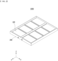
- Fig. 2 is a perspective view of a battery pack according to an embodiment of the present disclosure.
- Fig. 3 is a perspective view of a battery module included in the battery pack according to Fig. 2 .
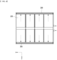
- Fig. 4 is a top view of the battery pack according to Fig. 2 .
- Fig. 5 is a partial cross-sectional view of the battery pack according to Fig. 2 .
- a battery pack 1000 includes at least one battery module 100, a pack frame 200 that houses the at least one battery module 100, and a venting flow path 300 formed between the battery module 100 and the pack frame 200.
- the battery module 100 may include a battery cell stack in which a plurality of battery cells are stacked, a module frame 120 that houses the battery cell stack, a busbar frame that is located on the front surface and/or rear surface of the battery cell stack, a busbar and/or a sensing unit mounted on the busbar frame, and the like.
- the components included in the battery module 100 are not limited thereto, and depending on the design, the battery module 100 may be provided in the state of omitting some of the above-mentioned components, and may be provided in the state of adding other components not mentioned herein.
- the type of battery cells included in the battery module 100 is not particularly limited, and pouch-type, prismatic, or jelly-roll type cylindrical battery cells can all be applied.
- the module frame 120 may include a metal having high thermal conductivity.
- the metal may be aluminum, gold, silver, copper, platinum or an alloy containing these. As the thermal conductivity of the metal is higher, the heat dissipation effect by the module frame improves, so that no specific range for thermal conductivity values is set.
- a venting part 130 may be located on one surface of the module frame 120.
- the venting part 130 can be for discharging gas, sparks, flame, or the like inside the module frame 120.
- the venting part 130 may be located on the lower part of one surface of the module frame 120.
- One surface of the module frame 120 on which the venting part 130 is formed may be a surface facing the electrode leads of the battery cell stack, the busbar frame, or the busbar.
- the shape of the venting part 130 may be varied, and for example, it may be an opening shape.
- the venting part 130 may be in the form of a plate that is broken at a predetermined pressure or higher, such as a rupture disc.
- it may be in the form of a valve that can be opened at a predetermined pressure or higher, such as a relief valve.
- a plurality of battery modules 100 may be provided in the battery pack 1000.
- the plurality of battery modules 100 may be arranged in rows and columns within the pack frame 200.
- the pack frame 200 can be for protecting the battery module 100 and electrical components connected thereto from external physical impact.
- the pack frame 200 may include a lower frame including a lower surface (bottom surface) and a side surface.
- the battery modules 100 are arranged in the inner space of the lower frame formed from the lower surface and the side surface, and then the upper plate or upper frame is coupled with the edge of the lower frame, thereby capable of sealing the pack frame 200.
- the upper plate or upper frame may be interpreted as being included in the pack frame 200, but this is not necessarily the case.
- the pack frame 200 may include a portion having high thermal conductivity in order to quickly dissipate heat generated in the internal space to the outside.
- the pack frame 200 may be made of a metal having high thermal conductivity, and examples thereof may be aluminum, gold, silver, copper, platinum, an alloy containing these, or the like.
- the pack frame 200 may partially have electrical insulation, and an insulating film may be provided at a position where insulation is required, or an insulating coating may be applied.
- a portion of the pack frame 200 to which an insulating film or an insulating coating is applied may be referred to as an insulating portion.
- the venting flow path 300 may be for discharging gas generated from the battery module 100 to the outside of the pack frame 200. As the venting flow path 300 restricts the venting path of gas, it is possible to minimize the influence of the high-temperature gas and the like discharged from the battery module 100 on the adjacent battery module 100.
- the venting flow path 300 may be formed in a separation space between the battery module 100 and the pack frame 200. Flames, gases, and the like discharged from each battery module 100 to the venting flow path 300 move along the venting flow path 300, so that it can be discharged to the outside through a discharge port provided in the pack frame 200.
- the venting flow path 300 may be preferably formed so as to correspond to all battery modules 100 within the battery pack 1000.
- the venting flow path 300 can be formed between the battery modules 100 and the pack frame 200 arranged in each row. Flames, gases, and the like discharged from the battery module 100 may move along the dotted line arrow through the venting flow path 300 to discharged through the discharge port.
- a venting part 130 may be located on one surface of the battery module 100 facing the venting flow path 300.
- the venting part 130 of the battery module 100 may be located toward the venting flow path 300.
- the battery module 100 may be arranged so that one surface on which the venting part 130 is formed faces the venting flow path 300.
- the venting flow path 300 may be formed extendedly along one surface of the pack frame 200 corresponding to the venting part 130.
- the venting flow path 300 is located so as to be spaced apart from the lower surface of the pack frame 200, and an empty space can be formed between the venting flow path 300 and the lower surface of the pack frame 200.
- the venting flow path 300 may be located on an upper side of the venting part 130 of the battery module 100.
- the venting part 130 is located so as to correspond to the empty space, and gas, flame, and the like discharged through the venting part 130 may be discharged into an empty space and then moved to the venting flow path 300 located on the upper side of the empty space.
- a filter mesh 400 may be located in the venting flow path 300.
- the filter mesh 400 may be formed on a lower surface of the venting flow path 300. Gas and flame discharged from the battery module 100 into the empty space may move to the venting flow path 300 through the filter mesh 400.
- the filter mesh 400 may be located parallel to the lower surface of the pack frame 200.
- the filter mesh 400 is arranged parallel to the lower surface of the pack frame 200, the gas and flame discharged from the battery module 100 pass through the filter mesh 400 and move to the venting flow path 300, and the spark may not move through the filter mesh 400.
- the release of high-temperature particles, that is, sparks is restricted by the filter mesh 400, the possibility of the spark coming into contact with external oxygen is lowered, which can prevent further ignition.
- the filter mesh 400 may be spaced apart from the lower surface of the pack frame 200.
- the filter mesh 400 may be located on an upper side of the venting part 130 of the battery module 100.
- the venting flow path 300 of the present embodiment is located on an upper side of the initial movement path of the gas discharged through the venting part 130, and gases and the like discharged from the battery module 100 may move in a direction opposite to gravity and move to the venting flow path 300 via the filter mesh 400. Therefore, particles and the like discharged from the battery module 100 and moved together with the gas can collide with the filter mesh 400 and then fall, thereby being able to prevent the filter mesh 400 from being blocked by particles or the like.
- Figs. 6 and 7 are diagrams for comparing effects according to positions of filters.
- Fig. 6 is an example in which the filter mesh 400 is formed perpendicular to the lower surface of the pack frame 200
- Fig. 7 is an example in which the filter mesh 400 is formed parallel to the lower surface of the pack frame 200.
- the gas or the like discharged from the battery module 100 is moved through the filter mesh 400, and the particles may be restricted in movement by the filter mesh 400 and may not be discharged to the outside.
- the filter mesh 400 of Fig. 6 Since the filter mesh 400 of Fig. 6 is arranged perpendicular to the initial movement direction of the gas discharged from the battery module 100, particles discharged together with the gas can collide with the filter mesh 400 without changing the direction.
- the filter mesh 400 of Fig. 6 has the advantage of effectively collecting a large number of particles, whereas as time passes, the opening of the filter mesh 400 can be blocked by particles, which causes a problem that the gas discharge path is sealed. As the particle closes an opening in the filter mesh 400, internal gas discharge is limited. This, after a predetermined time has elapsed, the opening of the filter mesh 400 may be closed, and the internal pressure of the battery pack 1000 increases, which may cause collapse or explosion of the pack frame 200.
- the filter mesh 400 of Fig. 7 is arranged parallel to the initial movement direction of the gas discharged from the battery module 100, particles discharged together with the gas may rise in a direction opposite to gravity and collide with the filter mesh 400. Therefore, when the filter mesh 400 is formed as shown in Fig. 7 , the particle is unlikely to collide with the filter mesh 400, or even if it collides, it may lose energy and fall.
- the filter mesh 400 of Fig. 7 may be less likely to be blocked by particles than the filter mesh 400 of Fig. 6 , which can minimize collapse or explosion problems of the pack frame 200 due to the closing of the filter mesh 400.
- the filter mesh 400 can be densely formed to have smaller openings.
- the filter mesh 400 may be desirable to form with a slightly large opening to prevent closure, but when it is provided in the form of Fig. 7 , such limitation is not necessary, which is thus advantageous for various designs.
- the battery pack according to one embodiment of the present disclosure may further include a battery management system (BMS) and/or a cooling device that control and manage battery's temperature, voltage, etc.
- BMS battery management system
- a cooling device that control and manage battery's temperature, voltage, etc.
- the battery pack according to an embodiment of the present disclosure can be applied to various devices.
- the device to which the battery pack is applied may be a vehicle means such as an electric bicycle, an electric vehicle, or a hybrid vehicle, but the above-mentioned device is not limited thereto, and the battery pack according to the present embodiment can be used for various devices in addition to the above illustrations, which also falls within the scope of the present disclosure.
Landscapes
- Chemical & Material Sciences (AREA)
- Chemical Kinetics & Catalysis (AREA)
- Electrochemistry (AREA)
- General Chemical & Material Sciences (AREA)
- Battery Mounting, Suspending (AREA)
- Gas Exhaust Devices For Batteries (AREA)
Abstract
A battery pack according to one embodiment of the present disclosure includes a battery module including a plurality of battery cells, and a pack frame that houses the battery module, wherein a venting flow path for discharging gas generated from the battery module is provided between the battery module and the pack frame, and wherein a filter mesh is formed on a lower surface of the venting flow path.
Description
- This application claims the benefit of
Korean Patent Application No. 10-2021-0149627 filed on November 3, 2021 - The present disclosure relates to a battery pack and a device including the same, and more particularly, to a battery pack that can prevent external ignition phenomena, and a device including the same.
- In modern society, as portable devices such as a mobile phone, a notebook computer, a camcorder and a digital camera has been daily used, the development of technologies in the fields related to mobile devices as described above has been activated. In addition, chargeable/dischargeable secondary batteries are used as a power source for an electric vehicle (EV), a hybrid electric vehicle (HEV), a plug-in hybrid electric vehicle (P-HEV) and the like, in an attempt to solve air pollution and the like caused by existing gasoline vehicles using fossil fuel. Therefore, the demand for development of the secondary battery is growing.
- Currently commercialized secondary batteries include a nickel cadmium battery, a nickel hydrogen battery, a nickel zinc battery, and a lithium secondary battery. Among them, the lithium secondary battery has come into the spotlight because they have advantages, for example, being freely charged and discharged, and having very low self-discharge rate and high energy density.
- Meanwhile, in the case of a secondary battery used for small-sized devices, two to three battery cells are used, but in the case of a secondary battery used for a middle or large-sized device such as an automobile, a battery module or a battery pack in which a large number of battery cells are electrically connected is used.
-
Fig. 1 shows a state before and after an ignition phenomenon of a mesh formed in a conventional battery pack. - Battery cells mounted in battery modules or battery packs can generate a large amount of heat in a charge and discharge process. If the temperature becomes higher than the proper temperature due to reasons such as overcharging, performance may deteriorate, and if the temperature rise is excessive, it may cause explosion or ignition. When the battery cell ignites, internal materials of the cell may be ejected along with high-temperature inflammable gas to the outside of the battery module or the battery pack. Such internal materials are mainly materials such as C, Cu, Al, Ni, Co, Mg, and Li, and are ejected in the form of high-temperature particles, that is, sparks.
- Meanwhile, such sparks not only can promote continuous thermal runaway phenomena within the battery module or the battery pack, but also when discharged to the outside, it causes problems of the external ignition phenomena due to contact with a flammable gas or an external oxygen. Therefore, in recent years, attempts have been made to form a mesh on a frame of a battery module or battery pack to minimize the release of particles
- However, even if a mesh is formed in the frame, when a particle closes an opening in the mesh as shown in
Fig. 1 , the release of internal gas is limited, and thus, the internal pressure of the battery module or pack increases rapidly, which causes problems of the explosion or damage to the frame. Therefore, there is a need for an effective frame structure that limits the release of sparks to the outside of the frame. - It is an object of the present disclosure to provide a battery pack having improved durability and safety by preventing external ignition phenomena caused by sparks, and a device including the same.
- However, the problem to be solved by embodiments of the present disclosure is not limited to the above-described problems, and can be variously expanded within the scope of the technical idea included in the present disclosure.
- According to one embodiment of the present disclosure, there is provided a battery pack comprising: a battery module including a plurality of battery cells, and a pack frame that houses the battery module, wherein a venting flow path for discharging gas generated from the battery module is provided between the battery module and the pack frame, and wherein a filter mesh is formed on a lower surface of the venting flow path.
- The filter mesh may be located parallel to the lower surface of the pack frame.
- The venting flow path may be located so as to be spaced apart from the lower surface of the pack frame.
- A venting part is formed on one surface of the battery module, and the battery module may be arranged so that one surface on which the venting part is formed faces the venting flow path.
- A venting part is formed on one surface of the battery module, and the battery module may be arranged so that one surface of the pack frame and the venting part face each other.
- The venting flow path may be located on the upper side of the venting part.
- The filter mesh may be located on the upper side of the venting part.
- The venting part may be in the form of a plate that is broken at a predetermined pressure or higher.
- The venting part may be in the form of a valve that is opened at a predetermined pressure or higher.
- According to another embodiment of the present disclosure, there is provided a device comprising at least one battery pack as described above.
- According to embodiments, the battery pack of the present disclosure prevents particles from being releases to the outside of the battery pack, thereby preventing ignition phenomena from being propagated to the outside of the battery pack.
- The effects of the present disclosure are not limited to the effects mentioned above and additional other effects not described above will be clearly understood from the detailed description and the appended drawings by those skilled in the art.
-
-
Fig. 1 shows a state before and after an ignition phenomenon of a mesh formed in a conventional battery pack; -
Fig. 2 is a perspective view of a battery pack according to an embodiment of the present disclosure; -
Fig. 3 is a perspective view of a battery module included in the battery pack according toFig. 2 ; -
Fig. 4 is a top view of the battery pack according toFig. 2 ; -
Fig. 5 is a partial cross-sectional view of the battery pack according toFig. 2 . -
Figs. 6 and 7 are diagrams for comparing effects according to positions of filters. - Hereinafter, various embodiments of the present disclosure will be described in detail with reference to the accompanying drawings so that those skilled in the art can easily carry out them. The present disclosure may be modified in various different ways, and is not limited to the embodiments set forth herein.
- Portions that are irrelevant to the description will be omitted to clearly describe the present disclosure, and like reference numerals designate like elements throughout the description.
- Further, in the drawings, the size and thickness of each element are arbitrarily illustrated for convenience of description, and the present disclosure is not necessarily limited to those illustrated in the drawings. In the drawings, the thickness of layers, regions, etc. are exaggerated for clarity. In the drawings, for convenience of description, the thicknesses of a part and an area are exaggerated.
- In addition, it will be understood that when an element such as a layer, film, region, or plate is referred to as being "on" or "above" another element, it can be directly on the other element or intervening elements may also be present. In contrast, when an element is referred to as being "directly on" another element, it means that other intervening elements are not present. Further, the word "on" or "above" means arranged on or below a reference portion, and does not necessarily mean being arranged on the upper end of the reference portion toward the opposite direction of gravity. Meanwhile, similarly to the case where it is described as being located "on" or "above" another part, the case where it is described as being located "below" or "under" another part will also be understood with reference to the above-mentioned contents.
- Further, the upper surface/lower surface of a specific member can be determined differently depending on which direction is used for a reference direction. Thus, throughout the description, 'upper surface' or 'lower surface' is defined as meaning two surfaces facing each other on the z-axis of the member. In addition, the side surface may mean a surface that is perpendicular to the upper surface or the lower surface.
- Further, throughout the description, when a portion is referred to as "including" or "comprising" a certain component, it means that the portion can further include other components, without excluding the other components, unless otherwise stated.
- Further, throughout the description, when it is referred to as "planar", it means when a target portion is viewed from the upper side, and when it is referred to as "cross-sectional", it means when a target portion is viewed from the side of a cross section cut vertically.
- Hereinafter, a battery pack according to one embodiment of the present disclosure will be described.
-
Fig. 2 is a perspective view of a battery pack according to an embodiment of the present disclosure.Fig. 3 is a perspective view of a battery module included in the battery pack according toFig. 2 .Fig. 4 is a top view of the battery pack according toFig. 2 .Fig. 5 is a partial cross-sectional view of the battery pack according toFig. 2 . - Referring to
Figs. 2 to 5 , abattery pack 1000 according to one embodiment of the present disclosure includes at least onebattery module 100, apack frame 200 that houses the at least onebattery module 100, and aventing flow path 300 formed between thebattery module 100 and thepack frame 200. - The
battery module 100 according to the present embodiment may include a battery cell stack in which a plurality of battery cells are stacked, amodule frame 120 that houses the battery cell stack, a busbar frame that is located on the front surface and/or rear surface of the battery cell stack, a busbar and/or a sensing unit mounted on the busbar frame, and the like. However, the components included in thebattery module 100 are not limited thereto, and depending on the design, thebattery module 100 may be provided in the state of omitting some of the above-mentioned components, and may be provided in the state of adding other components not mentioned herein. The type of battery cells included in thebattery module 100 is not particularly limited, and pouch-type, prismatic, or jelly-roll type cylindrical battery cells can all be applied. - The
module frame 120 may include a metal having high thermal conductivity. Examples of the metal may be aluminum, gold, silver, copper, platinum or an alloy containing these. As the thermal conductivity of the metal is higher, the heat dissipation effect by the module frame improves, so that no specific range for thermal conductivity values is set. - Meanwhile, a venting
part 130 may be located on one surface of themodule frame 120. When thebattery module 100 ignites, the ventingpart 130 can be for discharging gas, sparks, flame, or the like inside themodule frame 120. The ventingpart 130 may be located on the lower part of one surface of themodule frame 120. One surface of themodule frame 120 on which theventing part 130 is formed may be a surface facing the electrode leads of the battery cell stack, the busbar frame, or the busbar. - The shape of the venting
part 130 may be varied, and for example, it may be an opening shape. As another example, the ventingpart 130 may be in the form of a plate that is broken at a predetermined pressure or higher, such as a rupture disc. As yet another example, it may be in the form of a valve that can be opened at a predetermined pressure or higher, such as a relief valve. - As shown in
Figs. 2 and4 , a plurality ofbattery modules 100 may be provided in thebattery pack 1000. The plurality ofbattery modules 100 may be arranged in rows and columns within thepack frame 200. - The
pack frame 200 according to the present embodiment can be for protecting thebattery module 100 and electrical components connected thereto from external physical impact. Thepack frame 200 may include a lower frame including a lower surface (bottom surface) and a side surface. Thebattery modules 100 are arranged in the inner space of the lower frame formed from the lower surface and the side surface, and then the upper plate or upper frame is coupled with the edge of the lower frame, thereby capable of sealing thepack frame 200. Here, the upper plate or upper frame may be interpreted as being included in thepack frame 200, but this is not necessarily the case. - The
pack frame 200 may include a portion having high thermal conductivity in order to quickly dissipate heat generated in the internal space to the outside. For example, at least a portion of thepack frame 200 may be made of a metal having high thermal conductivity, and examples thereof may be aluminum, gold, silver, copper, platinum, an alloy containing these, or the like. Moreover, thepack frame 200 may partially have electrical insulation, and an insulating film may be provided at a position where insulation is required, or an insulating coating may be applied. A portion of thepack frame 200 to which an insulating film or an insulating coating is applied may be referred to as an insulating portion. - The venting
flow path 300 may be for discharging gas generated from thebattery module 100 to the outside of thepack frame 200. As theventing flow path 300 restricts the venting path of gas, it is possible to minimize the influence of the high-temperature gas and the like discharged from thebattery module 100 on theadjacent battery module 100. The ventingflow path 300 may be formed in a separation space between thebattery module 100 and thepack frame 200. Flames, gases, and the like discharged from eachbattery module 100 to theventing flow path 300 move along the ventingflow path 300, so that it can be discharged to the outside through a discharge port provided in thepack frame 200. - The venting
flow path 300 may be preferably formed so as to correspond to allbattery modules 100 within thebattery pack 1000. For example, as shown inFig. 4 , when thebattery modules 100 are arranged in 2 rows and 4 columns, the ventingflow path 300 can be formed between thebattery modules 100 and thepack frame 200 arranged in each row. Flames, gases, and the like discharged from thebattery module 100 may move along the dotted line arrow through the ventingflow path 300 to discharged through the discharge port. - A venting
part 130 may be located on one surface of thebattery module 100 facing the ventingflow path 300. The ventingpart 130 of thebattery module 100 may be located toward the ventingflow path 300. Thebattery module 100 may be arranged so that one surface on which theventing part 130 is formed faces the ventingflow path 300. As shown inFig. 4 , when the ventingflow path 300 is formed along the edge of thepack frame 200, thebattery module 100 may be arranged so that the ventingpart 130 is located toward thepack frame 200. The ventingflow path 300 may be formed extendedly along one surface of thepack frame 200 corresponding to the ventingpart 130. - Referring to
Fig. 5 , the ventingflow path 300 is located so as to be spaced apart from the lower surface of thepack frame 200, and an empty space can be formed between the ventingflow path 300 and the lower surface of thepack frame 200. The ventingflow path 300 may be located on an upper side of the ventingpart 130 of thebattery module 100. The ventingpart 130 is located so as to correspond to the empty space, and gas, flame, and the like discharged through the ventingpart 130 may be discharged into an empty space and then moved to theventing flow path 300 located on the upper side of the empty space. - A
filter mesh 400 may be located in theventing flow path 300. Thefilter mesh 400 may be formed on a lower surface of the ventingflow path 300. Gas and flame discharged from thebattery module 100 into the empty space may move to theventing flow path 300 through thefilter mesh 400. - The
filter mesh 400 may be located parallel to the lower surface of thepack frame 200. When thefilter mesh 400 is arranged parallel to the lower surface of thepack frame 200, the gas and flame discharged from thebattery module 100 pass through thefilter mesh 400 and move to theventing flow path 300, and the spark may not move through thefilter mesh 400. When the release of high-temperature particles, that is, sparks, is restricted by thefilter mesh 400, the possibility of the spark coming into contact with external oxygen is lowered, which can prevent further ignition. - The
filter mesh 400 may be spaced apart from the lower surface of thepack frame 200. Thefilter mesh 400 may be located on an upper side of the ventingpart 130 of thebattery module 100. When thefilter mesh 400 is formed on the lower surface of thepack frame 200, particles may fall in the direction of gravity and close an opening in thefilter mesh 400. However, the ventingflow path 300 of the present embodiment is located on an upper side of the initial movement path of the gas discharged through the ventingpart 130, and gases and the like discharged from thebattery module 100 may move in a direction opposite to gravity and move to theventing flow path 300 via thefilter mesh 400. Therefore, particles and the like discharged from thebattery module 100 and moved together with the gas can collide with thefilter mesh 400 and then fall, thereby being able to prevent thefilter mesh 400 from being blocked by particles or the like. -
Figs. 6 and 7 are diagrams for comparing effects according to positions of filters.Fig. 6 is an example in which thefilter mesh 400 is formed perpendicular to the lower surface of thepack frame 200, andFig. 7 is an example in which thefilter mesh 400 is formed parallel to the lower surface of thepack frame 200. - Referring to
Figs. 6 and 7 , the gas or the like discharged from thebattery module 100 is moved through thefilter mesh 400, and the particles may be restricted in movement by thefilter mesh 400 and may not be discharged to the outside. - Since the
filter mesh 400 ofFig. 6 is arranged perpendicular to the initial movement direction of the gas discharged from thebattery module 100, particles discharged together with the gas can collide with thefilter mesh 400 without changing the direction. Thefilter mesh 400 ofFig. 6 has the advantage of effectively collecting a large number of particles, whereas as time passes, the opening of thefilter mesh 400 can be blocked by particles, which causes a problem that the gas discharge path is sealed. As the particle closes an opening in thefilter mesh 400, internal gas discharge is limited. This, after a predetermined time has elapsed, the opening of thefilter mesh 400 may be closed, and the internal pressure of thebattery pack 1000 increases, which may cause collapse or explosion of thepack frame 200. - Meanwhile, since the
filter mesh 400 ofFig. 7 is arranged parallel to the initial movement direction of the gas discharged from thebattery module 100, particles discharged together with the gas may rise in a direction opposite to gravity and collide with thefilter mesh 400. Therefore, when thefilter mesh 400 is formed as shown inFig. 7 , the particle is unlikely to collide with thefilter mesh 400, or even if it collides, it may lose energy and fall. Thefilter mesh 400 ofFig. 7 may be less likely to be blocked by particles than thefilter mesh 400 ofFig. 6 , which can minimize collapse or explosion problems of thepack frame 200 due to the closing of thefilter mesh 400. - In addition, since the
filter mesh 400 is provided in the form ofFig. 7 , thefilter mesh 400 can be densely formed to have smaller openings. When thefilter mesh 400 is provided in the form ofFig. 6 , it may be desirable to form with a slightly large opening to prevent closure, but when it is provided in the form ofFig. 7 , such limitation is not necessary, which is thus advantageous for various designs. - Meanwhile, although not specifically mentioned above, the battery pack according to one embodiment of the present disclosure may further include a battery management system (BMS) and/or a cooling device that control and manage battery's temperature, voltage, etc.
- The battery pack according to an embodiment of the present disclosure can be applied to various devices. For example, the device to which the battery pack is applied may be a vehicle means such as an electric bicycle, an electric vehicle, or a hybrid vehicle, but the above-mentioned device is not limited thereto, and the battery pack according to the present embodiment can be used for various devices in addition to the above illustrations, which also falls within the scope of the present disclosure.
- Although preferred embodiments of the present disclosure have been described in detail above, the scope of the present disclosure is not limited thereto, and various modifications and improvements can be made by those skilled in the art using the basic concepts of the present disclosure which are defined in the appended claims, which also fall within the scope of the present disclosure.
-
- 1000: battery pack
- 100: battery module
- 200: pack frame
- 300: venting flow path
- 400: filter mesh
Claims (10)
- A battery pack comprising:a battery module including a plurality of battery cells, anda pack frame that houses the battery module,wherein a venting flow path for discharging gas generated from the battery module is provided between the battery module and the pack frame, andwherein a filter mesh is formed on a lower surface of the venting flow path.
- The battery pack according to claim 1, wherein:
the filter mesh is located parallel to the lower surface of the pack frame. - The battery pack according to claim 1, wherein:
the venting flow path is located so as to be spaced apart from the lower surface of the pack frame. - The battery pack according to claim 1, wherein:
a venting part is formed on one surface of the battery module, and the battery module is arranged so that one surface on which the venting part is formed faces the venting flow path. - The battery pack according to claim 1, wherein:
a venting part is formed on one surface of the battery module, and the battery module is arranged so that one surface of the pack frame and the venting part face each other. - The battery pack according to claim 4, wherein:
the venting flow path is located on the upper side of the venting part. - The battery pack according to claim 4, wherein:
the filter mesh is located on the upper side of the venting part. - The battery pack according to claim 4, wherein:
the venting part is in the form of a plate that is broken at a predetermined pressure or higher. - The battery pack according to claim 4, wherein:
the venting part is in the form of a valve that is opened at a predetermined pressure or higher. - A device comprising at least one battery pack as set forth in claim 1.
Applications Claiming Priority (2)
| Application Number | Priority Date | Filing Date | Title |
|---|---|---|---|
| KR1020210149627A KR20230064247A (en) | 2021-11-03 | 2021-11-03 | Battery pack and device including the same |
| PCT/KR2022/016489 WO2023080532A1 (en) | 2021-11-03 | 2022-10-26 | Battery pack and device including same |
Publications (1)
| Publication Number | Publication Date |
|---|---|
| EP4379932A1 true EP4379932A1 (en) | 2024-06-05 |
Family
ID=86241418
Family Applications (1)
| Application Number | Title | Priority Date | Filing Date |
|---|---|---|---|
| EP22890267.2A Pending EP4379932A1 (en) | 2021-11-03 | 2022-10-26 | Battery pack and device including same |
Country Status (5)
| Country | Link |
|---|---|
| EP (1) | EP4379932A1 (en) |
| JP (1) | JP2024530027A (en) |
| KR (1) | KR20230064247A (en) |
| CN (1) | CN118044046A (en) |
| WO (1) | WO2023080532A1 (en) |
Family Cites Families (6)
| Publication number | Priority date | Publication date | Assignee | Title |
|---|---|---|---|---|
| JP2007035444A (en) * | 2005-07-27 | 2007-02-08 | Toyota Motor Corp | Power pack |
| JP6279834B2 (en) * | 2013-02-20 | 2018-02-14 | ホーチキ株式会社 | Power storage device and moving body or facility using the same |
| KR102330377B1 (en) * | 2018-10-12 | 2021-11-22 | 주식회사 엘지에너지솔루션 | Battery module, battery rack comprising the battery module, and energy storage system comprising the battery rack |
| KR102400818B1 (en) * | 2019-03-06 | 2022-05-20 | 주식회사 엘지에너지솔루션 | A battery module having a structure capable of preventing air inflow into a module when a thermal runaway occurs, and a battery pack comprising the same |
| KR20210091514A (en) * | 2020-01-14 | 2021-07-22 | 주식회사 엘지에너지솔루션 | Gas venting device and battery pack comprising the same |
| KR102365176B1 (en) | 2020-06-01 | 2022-02-21 | 현대자동차 주식회사 | Retracable car seat |
-
2021
- 2021-11-03 KR KR1020210149627A patent/KR20230064247A/en active Search and Examination
-
2022
- 2022-10-26 CN CN202280065713.9A patent/CN118044046A/en active Pending
- 2022-10-26 EP EP22890267.2A patent/EP4379932A1/en active Pending
- 2022-10-26 JP JP2024506983A patent/JP2024530027A/en active Pending
- 2022-10-26 WO PCT/KR2022/016489 patent/WO2023080532A1/en active Application Filing
Also Published As
| Publication number | Publication date |
|---|---|
| KR20230064247A (en) | 2023-05-10 |
| WO2023080532A1 (en) | 2023-05-11 |
| JP2024530027A (en) | 2024-08-14 |
| CN118044046A (en) | 2024-05-14 |
Similar Documents
| Publication | Publication Date | Title |
|---|---|---|
| CN216698555U (en) | Battery module and battery pack including the same | |
| EP4184690A1 (en) | Battery module and battery pack comprising same | |
| JP2023543179A (en) | Battery packs and automobiles containing them | |
| KR20220103629A (en) | Battery module and battery pack including the same | |
| US20230318128A1 (en) | Battery module and battery pack including the same | |
| JP7528253B2 (en) | Battery module, battery pack and automobile including same | |
| EP4379932A1 (en) | Battery pack and device including same | |
| EP4254626A1 (en) | Battery pack and device including same | |
| KR20230070861A (en) | Battery pack and device including the same | |
| JP7528251B2 (en) | Battery module, battery pack and automobile including same | |
| US20240136649A1 (en) | Battery module and battery pack including the same | |
| EP4391184A1 (en) | Battery pack having double top cover with venting gas discharge passage180324 | |
| EP4199230A1 (en) | Flame arrester and battery pack including same | |
| EP4170793A1 (en) | Battery module and battery pack including same | |
| EP4425677A1 (en) | Battery pack and device including same | |
| EP4250452A1 (en) | Battery pack and device including same | |
| EP4164039A1 (en) | Battery pack and device including same | |
| KR20240003516A (en) | Battery module, battery pack and vehicle including the same | |
| KR20230097863A (en) | Battery pack and device including the same | |
| KR20240109837A (en) | Battery pack and device including the same | |
| CN118541850A (en) | Battery module with enhanced safety |
Legal Events
| Date | Code | Title | Description |
|---|---|---|---|
| STAA | Information on the status of an ep patent application or granted ep patent |
Free format text: STATUS: THE INTERNATIONAL PUBLICATION HAS BEEN MADE |
|
| PUAI | Public reference made under article 153(3) epc to a published international application that has entered the european phase |
Free format text: ORIGINAL CODE: 0009012 |
|
| STAA | Information on the status of an ep patent application or granted ep patent |
Free format text: STATUS: REQUEST FOR EXAMINATION WAS MADE |
|
| 17P | Request for examination filed |
Effective date: 20240301 |
|
| AK | Designated contracting states |
Kind code of ref document: A1 Designated state(s): AL AT BE BG CH CY CZ DE DK EE ES FI FR GB GR HR HU IE IS IT LI LT LU LV MC ME MK MT NL NO PL PT RO RS SE SI SK SM TR |