EP4379831A1 - Positive electrode material and battery - Google Patents
Positive electrode material and battery Download PDFInfo
- Publication number
- EP4379831A1 EP4379831A1 EP22849080.1A EP22849080A EP4379831A1 EP 4379831 A1 EP4379831 A1 EP 4379831A1 EP 22849080 A EP22849080 A EP 22849080A EP 4379831 A1 EP4379831 A1 EP 4379831A1
- Authority
- EP
- European Patent Office
- Prior art keywords
- positive electrode
- conductive material
- solid electrolyte
- equal
- active material
- Prior art date
- Legal status (The legal status is an assumption and is not a legal conclusion. Google has not performed a legal analysis and makes no representation as to the accuracy of the status listed.)
- Pending
Links
Images


Classifications
-
- H—ELECTRICITY
- H01—ELECTRIC ELEMENTS
- H01M—PROCESSES OR MEANS, e.g. BATTERIES, FOR THE DIRECT CONVERSION OF CHEMICAL ENERGY INTO ELECTRICAL ENERGY
- H01M4/00—Electrodes
- H01M4/02—Electrodes composed of, or comprising, active material
- H01M4/62—Selection of inactive substances as ingredients for active masses, e.g. binders, fillers
- H01M4/624—Electric conductive fillers
- H01M4/625—Carbon or graphite
-
- H—ELECTRICITY
- H01—ELECTRIC ELEMENTS
- H01M—PROCESSES OR MEANS, e.g. BATTERIES, FOR THE DIRECT CONVERSION OF CHEMICAL ENERGY INTO ELECTRICAL ENERGY
- H01M10/00—Secondary cells; Manufacture thereof
- H01M10/05—Accumulators with non-aqueous electrolyte
- H01M10/056—Accumulators with non-aqueous electrolyte characterised by the materials used as electrolytes, e.g. mixed inorganic/organic electrolytes
- H01M10/0561—Accumulators with non-aqueous electrolyte characterised by the materials used as electrolytes, e.g. mixed inorganic/organic electrolytes the electrolyte being constituted of inorganic materials only
- H01M10/0562—Solid materials
-
- H—ELECTRICITY
- H01—ELECTRIC ELEMENTS
- H01M—PROCESSES OR MEANS, e.g. BATTERIES, FOR THE DIRECT CONVERSION OF CHEMICAL ENERGY INTO ELECTRICAL ENERGY
- H01M10/00—Secondary cells; Manufacture thereof
- H01M10/05—Accumulators with non-aqueous electrolyte
- H01M10/052—Li-accumulators
-
- H—ELECTRICITY
- H01—ELECTRIC ELEMENTS
- H01M—PROCESSES OR MEANS, e.g. BATTERIES, FOR THE DIRECT CONVERSION OF CHEMICAL ENERGY INTO ELECTRICAL ENERGY
- H01M4/00—Electrodes
- H01M4/02—Electrodes composed of, or comprising, active material
- H01M4/13—Electrodes for accumulators with non-aqueous electrolyte, e.g. for lithium-accumulators; Processes of manufacture thereof
- H01M4/131—Electrodes based on mixed oxides or hydroxides, or on mixtures of oxides or hydroxides, e.g. LiCoOx
-
- H—ELECTRICITY
- H01—ELECTRIC ELEMENTS
- H01M—PROCESSES OR MEANS, e.g. BATTERIES, FOR THE DIRECT CONVERSION OF CHEMICAL ENERGY INTO ELECTRICAL ENERGY
- H01M4/00—Electrodes
- H01M4/02—Electrodes composed of, or comprising, active material
- H01M4/36—Selection of substances as active materials, active masses, active liquids
- H01M4/362—Composites
-
- H—ELECTRICITY
- H01—ELECTRIC ELEMENTS
- H01M—PROCESSES OR MEANS, e.g. BATTERIES, FOR THE DIRECT CONVERSION OF CHEMICAL ENERGY INTO ELECTRICAL ENERGY
- H01M4/00—Electrodes
- H01M4/02—Electrodes composed of, or comprising, active material
- H01M4/36—Selection of substances as active materials, active masses, active liquids
- H01M4/362—Composites
- H01M4/366—Composites as layered products
-
- H—ELECTRICITY
- H01—ELECTRIC ELEMENTS
- H01M—PROCESSES OR MEANS, e.g. BATTERIES, FOR THE DIRECT CONVERSION OF CHEMICAL ENERGY INTO ELECTRICAL ENERGY
- H01M4/00—Electrodes
- H01M4/02—Electrodes composed of, or comprising, active material
- H01M4/36—Selection of substances as active materials, active masses, active liquids
- H01M4/48—Selection of substances as active materials, active masses, active liquids of inorganic oxides or hydroxides
- H01M4/50—Selection of substances as active materials, active masses, active liquids of inorganic oxides or hydroxides of manganese
- H01M4/505—Selection of substances as active materials, active masses, active liquids of inorganic oxides or hydroxides of manganese of mixed oxides or hydroxides containing manganese for inserting or intercalating light metals, e.g. LiMn2O4 or LiMn2OxFy
-
- H—ELECTRICITY
- H01—ELECTRIC ELEMENTS
- H01M—PROCESSES OR MEANS, e.g. BATTERIES, FOR THE DIRECT CONVERSION OF CHEMICAL ENERGY INTO ELECTRICAL ENERGY
- H01M4/00—Electrodes
- H01M4/02—Electrodes composed of, or comprising, active material
- H01M4/36—Selection of substances as active materials, active masses, active liquids
- H01M4/48—Selection of substances as active materials, active masses, active liquids of inorganic oxides or hydroxides
- H01M4/52—Selection of substances as active materials, active masses, active liquids of inorganic oxides or hydroxides of nickel, cobalt or iron
- H01M4/525—Selection of substances as active materials, active masses, active liquids of inorganic oxides or hydroxides of nickel, cobalt or iron of mixed oxides or hydroxides containing iron, cobalt or nickel for inserting or intercalating light metals, e.g. LiNiO2, LiCoO2 or LiCoOxFy
-
- H—ELECTRICITY
- H01—ELECTRIC ELEMENTS
- H01M—PROCESSES OR MEANS, e.g. BATTERIES, FOR THE DIRECT CONVERSION OF CHEMICAL ENERGY INTO ELECTRICAL ENERGY
- H01M4/00—Electrodes
- H01M4/02—Electrodes composed of, or comprising, active material
- H01M2004/021—Physical characteristics, e.g. porosity, surface area
-
- H—ELECTRICITY
- H01—ELECTRIC ELEMENTS
- H01M—PROCESSES OR MEANS, e.g. BATTERIES, FOR THE DIRECT CONVERSION OF CHEMICAL ENERGY INTO ELECTRICAL ENERGY
- H01M4/00—Electrodes
- H01M4/02—Electrodes composed of, or comprising, active material
- H01M2004/026—Electrodes composed of, or comprising, active material characterised by the polarity
- H01M2004/028—Positive electrodes
-
- H—ELECTRICITY
- H01—ELECTRIC ELEMENTS
- H01M—PROCESSES OR MEANS, e.g. BATTERIES, FOR THE DIRECT CONVERSION OF CHEMICAL ENERGY INTO ELECTRICAL ENERGY
- H01M2300/00—Electrolytes
- H01M2300/0017—Non-aqueous electrolytes
- H01M2300/0065—Solid electrolytes
- H01M2300/0068—Solid electrolytes inorganic
-
- Y—GENERAL TAGGING OF NEW TECHNOLOGICAL DEVELOPMENTS; GENERAL TAGGING OF CROSS-SECTIONAL TECHNOLOGIES SPANNING OVER SEVERAL SECTIONS OF THE IPC; TECHNICAL SUBJECTS COVERED BY FORMER USPC CROSS-REFERENCE ART COLLECTIONS [XRACs] AND DIGESTS
- Y02—TECHNOLOGIES OR APPLICATIONS FOR MITIGATION OR ADAPTATION AGAINST CLIMATE CHANGE
- Y02E—REDUCTION OF GREENHOUSE GAS [GHG] EMISSIONS, RELATED TO ENERGY GENERATION, TRANSMISSION OR DISTRIBUTION
- Y02E60/00—Enabling technologies; Technologies with a potential or indirect contribution to GHG emissions mitigation
- Y02E60/10—Energy storage using batteries
Definitions
- the present disclosure relates to a positive electrode material and a battery.
- PTL 1 discloses a solid-state battery including a positive electrode containing an active material, a fibrous conductive material, a granular conductive material, and a solid electrolyte.
- the positive electrode has both high energy density and high electron conductivity in the conventional technology.
- a positive electrode material according to an aspect of the present disclosure includes:
- the positive electrode can have both high energy density and high electron conductivity.
- PTL 1 discloses a solid-state battery including a positive electrode containing an active material, a fibrous conductive material, a granular conductive material, and a solid electrolyte.
- the amount of the active material is about 60 parts by mass relative to the total amount, 100 parts by mass, of the active material, the fibrous conductive material, the granular conductive material, and the solid electrolyte.
- the ratio of the volume of the active material to the total volume of the active material, the fibrous conductive material, the granular conductive material, and the solid electrolyte in the positive electrode material in PTL 1 is about 43%.
- the volume ratio of the solid electrolyte having electron-insulating properties is larger than that of the active material.
- the ratio of the electron conductive material may be increased to improve the electron conductivity.
- the energy density of the positive electrode decreases because the ratio of the active material decreases.
- a positive electrode material includes: a mixture of a positive electrode active material, a solid electrolyte, and a conductive material, wherein the conductive material contains a first conductive material having an average major axis diameter of greater than or equal to 1 ⁇ m and a second conductive material having an average particle diameter of less than or equal to 100 nm, and a ratio of a volume of the positive electrode active material to a total volume of the positive electrode active material and the solid electrolyte is greater than or equal to 60% and less than or equal to 90%.
- the volume ratio of the positive electrode active material is larger than that of the solid electrolyte. This can increase the energy density of the positive electrode.
- the first conductive material has an average major axis diameter of greater than or equal to 1 ⁇ m. This allows easy connection between the first conductive material and the second conductive material in the positive electrode. Thus, an electron conduction network can be efficiently formed in the positive electrode. With this configuration, the positive electrode can have both high energy density and high electron conductivity.
- the ratio of the volume of the positive electrode active material to the total volume of the positive electrode active material and the solid electrolyte may be greater than or equal to 65% and less than or equal to 85%. This configuration can further increase the energy density of the positive electrode.
- the ratio of the volume of the positive electrode active material to the total volume of the positive electrode active material and the solid electrolyte may be greater than or equal to 67% and less than or equal to 75%. This configuration can further increase the energy density of the positive electrode.
- a mass ratio of the conductive material may be less than or equal to 3 with a mass ratio of the positive electrode active material being taken as 100. This configuration can reduce the possibility that the conductive material will inhibit lithium-ion conduction between the positive electrode active material and the solid electrolyte.
- a ratio of a mass of the second conductive material to a mass of the conductive material is less than or equal to 80%. This configuration can further improve the electron conductivity of the positive electrode.
- the ratio of the mass of the second conductive material to the mass of the conductive material may be greater than or equal to 5% and less than or equal to 50%. This configuration can further improve the electron conductivity of the positive electrode.
- the ratio of the mass of the second conductive material to the mass of the conductive material may be greater than or equal to 6% and less than or equal to 25%. This configuration can further improve the electron conductivity of the positive electrode.
- the first conductive material may have an average major axis diameter of greater than or equal to 4 ⁇ m. This configuration is likely to allow the first conductive material to form a conduction path that enables long-distance electron conduction in the positive electrode. This can further improve the electron conductivity of the positive electrode.
- the second conductive material may have an average particle diameter of less than or equal to 25 nm. This configuration is more likely to allow the second conductive material to attach to the surface of the positive electrode active material. Thus, an electron conduction network is readily formed in the positive electrode because the first conductive material and the second conductive material are connected to each other.
- the first conductive material and the second conductive material may contain a carbon material. This configuration can further improve the electron conductivity of the positive electrode.
- the first conductive material may contain a fibrous carbon material. This configuration can further improve the electron conductivity of the positive electrode.
- the second conductive material may contain carbon black. This configuration can further improve the electron conductivity of the positive electrode.
- the carbon black may contain acetylene black. This configuration can further improve the electron conductivity of the positive electrode.
- the solid electrolyte may contain at least one selected from the group consisting of a sulfide solid electrolyte and a halide solid electrolyte. This configuration can improve the output properties of the battery.
- the positive electrode active material may have a layered rock-salt structure.
- the layered rock salt structure in which transition metal and lithium are regularly arranged to form a two-dimensional plane allows two-dimensional diffusion of lithium.
- this configuration can increase the energy density of the battery.
- the positive electrode material according to any one of the first to fifteenth aspects may further include a coating layer covering at least a portion of a surface of the positive electrode active material. This configuration can further lower the resistance in the battery.
- a battery according to a seventeenth aspect of the present disclosure includes: a positive electrode containing a positive electrode material according to any one of the first to sixteenth aspects, a negative electrode, and an electrolyte layer disposed between the positive electrode and the negative electrode.
- the above configuration enables the positive electrode to have both high energy density and high electron conductivity. This can increase the energy density of the battery and also can reduce the resistance in the battery.
- the electrolyte layer may contain a sulfide solid electrolyte. This configuration can improve the output properties of the battery.
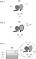
- Fig. 1 is a cross-sectional view illustrating a schematic configuration of a positive electrode material 1000 according to a first embodiment.
- the positive electrode material 1000 contains a mixture of a positive electrode active material 110, a solid electrolyte 100, and a conductive material 140.
- the conductive material 140 contains a first conductive material 150 having an average major axis diameter of greater than or equal to 1 ⁇ m and a second conductive material 160 having an average particle diameter of less than or equal to 100 nm.
- the ratio of the volume of the positive electrode active material 110 to the total volume of the positive electrode active material 110 and the solid electrolyte 100 is greater than or equal to 60% and less than or equal to 90%.
- the volume content of the positive electrode active material 110 is larger than that of the solid electrolyte 100. This can increase the energy density of the positive electrode.
- the first conductive material 150 has an average major axis diameter of greater than or equal to 1 ⁇ m. This allows the first conductive material 150 and the second conductive material 160 to be readily connected in the positive electrode. Thus, an electron conduction network can be efficiently formed in the positive electrode. This enables the positive electrode to have both high energy density and high electron conductivity.
- the average major axis diameter of the first conductive material 150 can be measured, for example, in a SEM image produced by a scanning electron microscope. Specifically, the average major axis diameter is obtained by calculating the average of the major axis diameters of 20 randomly selected particles of the first conductive material 150 in a SEM image.
- the major axis diameter of the first conductive material 150 is defined as a diameter of the smallest-area circle that encloses a particle of the first conductive material 150, in a SEM image of the particles of the first conductive material 150.
- the average particle diameter of the second conductive material 160 can be measured, for example, using a TEM image produced by a transmission electron microscope (TEM). Specifically, the average particle diameter is obtained by calculating the average of the equivalent area diameters of 20 randomly selected particles of the second conductive material 160 in a TEM image.
- TEM transmission electron microscope
- the average major diameter axis of the first conductive material and the average particle diameter of the second conductive material in the positive electrode material can be measured, for example, by the following method.
- the positive electrode material is scraped from the battery without being mixed with the negative electrode material, and thus the positive electrode material is obtained.
- the obtained positive electrode material is mixed with water to dissolve the solid electrolyte and filtered to separate out the active material, the binder, and the conductive material, which are materials other than the solid electrolyte.
- the separated active material, binder, and conductive material are mixed with an organic solvent such as toluene to dissolve the binder and filtered to separate out the active material and the conductive material.
- the separated active material and conductive material are mixed with an acid solution to dissolve the active material and filtered to separate out the conductive material.
- the separated conductive material is then dried.
- the dried conductive material enables the above-described measurement of the average major axis diameter of the first conductive material using a SEM image and the above-described measurement of the average particle diameter of the second conductive material using a TEM image.
- the ratio of the volume of the positive electrode active material 110 to the total volume of the positive electrode active material 110 and the solid electrolyte 100 can be calculated, for example, by the following method.
- the positive electrode active material 110 contained in the positive electrode material 1000 can be separated out, for example, by dissolving only the solid electrolyte 100 in a solvent.
- the total mass of the positive electrode active material 110 and the solid electrolyte 100 and the mass of the positive electrode active material 110 can be obtained from the masses before and after the above dissolution.
- the specific gravity of each of the positive electrode active material 110 and the solid electrolyte 100 can be obtained from literature, for example.
- the ratio of the volume of the positive electrode active material 110 to the total volume of positive electrode active material 110 and the solid electrolyte 100 can be calculated by using these values.
- the ratio of the volume of the positive electrode active material 110 to the total volume of the positive electrode active material 110 and the solid electrolyte 100 may be greater than or equal to 65% and less than or equal to 85%. This configuration can further increase the energy density of the positive electrode.
- the ratio of the volume of the positive electrode active material 110 to the total volume of the positive electrode active material 110 and the solid electrolyte 100 may be greater than or equal to 67% and less than or equal to 75%. This configuration can further increase the energy density of the positive electrode.
- the mass ratio of the conductive material 140 may be less than or equal to 3 with the mass ratio of the positive electrode active material 110 being taken as 100. This configuration can reduce the possibility that the conductive material 140 will inhibit the lithium-ion conduction between the positive electrode active material 110 and the solid electrolyte 100.
- the mass ratio of the conductive material 140 with the mass ratio of the positive electrode active material 110 being taken as 100 can be calculated by the following method.
- the mass of the positive electrode active material 110 contained in the positive electrode material 1000 can be obtained by the method described above.
- the mass of the conductive material 140 in the positive electrode material 1000 can be obtained, for example, from a decrease in mass caused by high-temperature pyrolysis.
- the mass ratio of the conductive material 140 with the mass ratio of the positive electrode active material 110 being taken as 100 can be calculated using these values.
- the ratio of the mass of the second conductive material 160 to the mass of the conductive material 140 may be less than or equal to 80%. This configuration can further improve the electron conductivity of the positive electrode.
- the ratio of the mass of the second conductive material 160 to the mass of the conductive material 140 can be calculated, for example, by the following method.
- the mass of the second conductive material 160 relative to the mass of the conductive material 140 can be obtained by particle size distribution measurement or classification. In this way, the ratio of the mass of the second conductive material 160 to the mass of the conductive material 140 can be calculated.
- the ratio of the mass of the second conductive material 160 to the mass of the conductive material 140 may be greater than or equal to 5% and less than or equal to 50%. This configuration can further improve the electron conductivity of the positive electrode.
- the ratio of the mass of the second conductive material 160 to the mass of the conductive material 140 may be greater than or equal to 6% and less than or equal to 25%. This configuration can further improve the electron conductivity of the positive electrode.
- the first conductive material 150 and the second conductive material 160 may contain a carbon material. This configuration can further improve the electron conductivity of the positive electrode.
- the first conductive material 150 and the second conductive material 160 may be a carbon material. This configuration can further improve the electron conductivity of the positive electrode.
- the first conductive material 150 may contain a fibrous carbon material. This configuration can further improve the electron conductivity of the positive electrode.
- the first conductive material 150 may be a fibrous carbon material. This configuration can further improve the electron conductivity of the positive electrode.
- the fibrous carbon material examples include fibrous carbons such as vapor grown carbon fibers, carbon nanotubes, and carbon nanofibers. If the first conductive material 150 contains a fibrous carbon material, the first conductive material 150 may contain any one of the above materials or two or more of the above materials. When the first conductive material 150 is a fibrous carbon material, the first conductive material 150 may be composed of any one of the above materials or two or more of the above materials.
- the second conductive material 160 may contain carbon black. This configuration can further improve the electron conductivity of the positive electrode.
- the second conductive material 160 may be carbon black. This configuration can further improve the electron conductivity of the positive electrode.
- the carbon black examples include acetylene black and Ketjen black.
- the second conductive material 160 may contain acetylene black or Ketjen black.
- the second conductive material 160 may contain any of acetylene black and Ketjen black.
- the carbon black that contains acetylene black can further improve the electron conductivity of the positive electrode.
- the second conductive material 160 may be carbon black, the second conductive material 160 may be acetylene black or Ketjen black.
- the second conductive material 160 may be composed of acetylene black and Ketjen black.
- the first conductive material 150 is a fibrous carbon material
- the first conductive material 150 that contains the fibrous carbon material as a main component may further contain inevitable impurities, starting raw materials used in synthesis of the fibrous carbon material, by-products, degraded products, or the like.
- the "main component” means a component most abundant by mass.
- the first conductive material 150 may, for example, contain a fibrous carbon material in a mass ratio of 100% to the whole first conductive material 150, excluding inevitable impurities.
- the first conductive material 150 may be composed solely of the fibrous carbon material.
- the second conductive material 160 is carbon black
- the second conductive material 160 that contains carbon black as a main component may further contain inevitable impurities, starting raw materials used in synthesis of the carbon black, by-products, degraded products, or the like.
- the second conductive material 160 may, for example, contain carbon black in a mass ratio of 100% to the whole second conductive material 160, excluding inevitable impurities.
- the second conductive material 160 may be composed solely of carbon black.
- the first conductive material 150 may have an average major axis diameter of greater than or equal to 4 ⁇ m. This configuration is likely to allow the first conductive material 150 to form a conduction path that enables long-distance electron conduction in the positive electrode. This can further improve the electron conductivity of the positive electrode.
- the second conductive material 160 may have an average particle diameter of less than or equal to 25 nm. This configuration allows the second conductive material 160 to readily attach to the surface of the positive electrode active material 110. Thus, an electron conduction network is readily formed in the positive electrode because the first conductive material 150 and the second conductive material 160 are connected to each other.
- the first conductive material 150 may have any shape that has an average major axis diameter of greater than or equal to 1 ⁇ m.
- the first conductive material 150 may be, for example, fibrous or acicular.
- the shape of the first conductive material 150 may be fibrous.
- the second conductive material 160 may have any shape that has the average particle diameter of less than or equal to 100 nm.
- the second conductive material 160 may be, for example, spherical or ellipsoidal.
- the shape of the second conductive material 160 may be spherical.
- the conductive material 140 may contain a conductive material different from the first conductive material 150 and the second conductive material 160.
- a conductive material include graphites such as natural graphite and artificial graphite, metal fibers, fluorocarbons, metal powders such as aluminum, conductive whiskers such as zinc oxide and potassium titanate, conductive metal oxides such as titanium oxide, and conductive polymer compounds such as polyaniline, polypyrrole, and polythiophene. This configuration can further improve the electron conductivity of the positive electrode.
- the conductive material 140 may be composed only of the first conductive material 150 and the second conductive material 160. In other words, the conductive material 140 does not have to contain a conductive material different from the first conductive material 150 and the second conductive material 160.
- the positive electrode active material 110 a material that can be used as a positive electrode active material of all-solid-state lithium-ion batteries may be used.
- the positive electrode active material 110 include LiCoO 2 , LiNi x Me 1-x O 2 , LiNi x Co 1-x O 2 , LiNi 1/3 Co 1/3 Mn 1/3 O 2 , LiMnO 2 , different- element substituted Li-Mn spinel, lithium titanate, lithium metal phosphate, and transition metal oxide.
- LiNi x Me 1-x O 2 x satisfies 0.5 ⁇ x ⁇ 1 and Me contains at least one selected from the group consisting of Co, Mn, and Al.
- LiNi x Co 1-x O 2 x satisfies 0 ⁇ x ⁇ 0.5.
- Examples of different-element substituted Li-Mn spinel include LiMn 1.5 Ni 0.5 O 4 , LiMn 1.5 Al 0.5 O 4 , LiMn 1.5 Mg 0.5 O 4 , LiMn 1.5 Co 0.5 O 4 , LiMn 1.5 Fe 0.5 O 4 , and LiMn 1.5 Zn 0.5 O 4 .
- An example of lithium titanate is Li 4 Ti 5 O 12 .
- lithium metal phosphate include LiFePO 4 , LiMnPO 4 , LiCoPO 4 , and LiNiPO 4 .
- Examples of transition metal oxide include V 2 O 5 and MoO 3 .
- the positive electrode active material 110 may be a lithium-containing composite oxide selected from the group consisting of LiCoO 2 , LiNi x Me 1-x O 2 , LiNi x Co 1-x O 2 , LiNi 1/3 Co 1/3 Mn 1/3 O 2 , LiMnO 2 , different-element substituted Li-Mn spinel, and lithium metal phosphate.
- the positive electrode active material 110 is a lithium-containing composite oxide
- the positive electrode active material 110 may have a layered rock-salt structure.
- the layered rock salt structure in which transition metal and lithium are regularly arranged to form a two-dimensional plane allows two-dimensional diffusion of lithium. Thus, this configuration can increase the energy density of the battery.
- the solid electrolyte 100 may contain at least one selected from the group consisting of a sulfide solid electrolyte and a halide solid electrolyte. This configuration can improve the output properties of the battery.
- Examples of the sulfide solid electrolyte include Li 2 S-P 2 S 5 , Li 2 S-SiS 2 , Li 2 S-B 2 S 3 , Li 2 S-GeS 2 , Li 3.25 Ge 0 . 25 P 0.75 S 4 , and Li 10 GeP 2 S 12 .
- the sulfide solid electrolyte may be Argyrodite sulfide solid electrolyte such as Li 6 PS 5 Cl, Li 6 PS 5 Br, and Li 6 PS 5 I.
- the sulfide solid electrolytes may additionally contain LiX, Li 2 O, MO q , or Li p MO q , for example.
- X represents at least one selected from the group consisting of F, Cl, Br, and I.
- M represents at least one selected from the group consisting of P, Si, Ge, B, Al, Ga, In, Fe, and Zn.
- Each of p and q represents a natural number.
- One or more sulfide solid electrolytes selected from the above materials may be used.
- the above configuration can further improve the ionic conductivity of the sulfide solid electrolyte. This can improve the charge and discharge efficiency of the battery.
- the halide solid electrolyte may be represented by Formula 1 below. Li ⁇ M ⁇ X ⁇ Formula (1)
- M includes at least one element selected from the group consisting of metallic elements other than Li and metalloid elements.
- X includes at least one selected from the group consisting of F, Cl, Br, and I.
- the "metalloid elements” include B, Si, Ge, As, Sb, and Te.
- the “metallic elements” include all elements of group 1 to group 12 of the periodic table except for hydrogen and all elements of group 13 to group 16 of the periodic table except for B, Si, Ge, As, Sb, Te, C, N, P, O, S, and Se.
- “metalloid elements” or “metallic elements” are elements that can become a cation when forming an inorganic compound with a halogen compound.
- Halide solid electrolytes represented by Formula 1 have higher ionic conductivity than halide solid electrolytes such as LiI, which are composed of Li and a halogen element. Thus, the halide solid electrolyte represented by Formula 1 can have further higher ionic conductivity.
- M may represent at least one element selected from the group consisting of metallic elements other than Li and metalloid elements.
- X may represent at least one selected from the group consisting of F, Cl, Br, and I.
- M may include Y, or yttrium.
- the halide solid electrolyte may contain Y as a metallic element. This configuration can further improve the ionic conductivity of the halide solid electrolyte.
- Me may represent, for example, at least one selected from the group consisting of Mg, Ca, Sr, Ba, Zn, Sc, Al, Ga, Bi, Zr, Hf, Ti, Sn, Ta, and Nb.
- the above configuration can further improve the ionic conductivity of the halide solid electrolyte.
- the following materials may be used, for example.
- the following configuration can further improve the ionic conductivity of the halide solid electrolyte.
- the halide solid electrolyte may be a material represented by Formula A1 below. Li 6-3d Y d X e Formula (A1)
- X represents at least one selected from the group consisting of F, Cl, Br, and I. Furthermore, 0 ⁇ d ⁇ 2 is satisfied.
- the halide solid electrolyte may be a material represented by Formula A2 below. Li 3 YX 6 Formula (A2)
- X represents at least one selected from the group consisting of F, Cl, Br, and I.
- the halide solid electrolyte may be a material represented by Formula A3 below. Li 3-3 ⁇ Y 1+ ⁇ Cl 6 Formula (A3)
- the halide solid electrolyte may be a material represented by Formula A4 below. Li 3-3 ⁇ Y 1+ ⁇ Br 6 Formula (A4)
- the halide solid electrolyte may be a material represented by Formula A5 below. Li 3-3 ⁇ +a Y 1+ ⁇ -a Me a Cl 6-x-y Br x I y Formula (A5)
- Me contains at least one selected from the group consisting of Mg, Ca, Sr, Ba, and Zn. Me may be at least one selected from the group consisting of Mg, Ca, Sr, Ba, and Zn.
- the halide solid electrolyte may be a material represented by Formula A6 below. Li 3-3 ⁇ Y 1+ ⁇ -a Me a Cl 6-x-y Br x I y Formula (A6)
- Me contains at least one selected from the group consisting of Al, Sc, Ga, and Bi. Me may be at least one selected from the group consisting of Al, Sc, Ga, and Bi.
- the halide solid electrolyte may be a material represented by Formula A7 below. Li 3-3 ⁇ -a Y 1+ ⁇ -a Me a Cl 6-x-y Br x I y Formula (A7)
- Me contains at least one selected from the group consisting of Zr, Hf and Ti. Me may be at least one selected from the group consisting of Zr, Hf, and Ti.
- the halide solid electrolyte may be a material represented by Formula A8 below. Li 3-3 ⁇ -2a Y 1+ ⁇ -a Me a Cl 6-x-y Br x I y Formula (A8)
- Me contains at least one selected from the group consisting of Ta and Nb. Me may be at least one selected from the group consisting of Ta and Nb.
- halide solid electrolyte examples include Li 3 YX 6 , Li 2 MgX 4 , Li 2 FeX 4 , Li(Al,Ga,In)X 4 , and Li 3 (Al,Ga,In)X 6 .
- X represents at least one selected from the group consisting of F, Cl, Br, and I.
- (A,B,C) in a formula means "at least one selected from the group consisting of A, B, and C".
- (Al,Ga,In) is synonymous with “at least one selected from the group consisting of Al, Ga, and In”. The same holds for the other elements.
- the solid electrolyte material does not have to contain sulfur. This configuration can reduce generation of hydrogen sulfide gas. Thus, safer batteries can be produced.
- the solid electrolyte 100 may have any shape.
- the shape of the solid electrolyte 100 may be, for example, acicular, spherical, or ellipsoidal.
- the shape of the solid electrolyte 100 may be particulate.
- the median diameter of the solid electrolyte 100 may be less than or equal to 100 ⁇ m.
- the positive electrode active material 110 and the solid electrolyte 100 can be favorably dispersed in the positive electrode material 1000. This improves the charge and discharge properties of the battery.
- the median diameter of the solid electrolyte 100 may be less than or equal to 10 ⁇ m. With this configuration, the positive electrode active material 110 and the solid electrolyte 100 can be favorably dispersed in the positive electrode material 1000.
- the median diameter of the solid electrolyte 100 may be smaller than that of the positive electrode active material 110. With this configuration, the positive electrode active material 110 and the solid electrolyte 100 can be more favorably dispersed in the positive electrode material 1000.
- the median diameter of the positive electrode active material 110 may be greater than or equal to 0.1 ⁇ m and less than or equal to 100 ⁇ m. When the median diameter of the positive electrode active material 110 is greater than or equal to 0.1 ⁇ m, the positive electrode active material 110 and the solid electrolyte 100 can be favorably dispersed in the positive electrode material 1000. This improves the charge and discharge properties of the battery.
- the positive electrode active material 110 having the median diameter of less than or equal to 100 ⁇ m allows the lithium diffusion rate in the positive electrode active material 110 to be sufficiently high. This enables the battery to operate with a high output.
- the median diameter of the positive electrode active material 110 may be larger than that of the solid electrolyte 100. With this configuration, the positive electrode active material 110 and the solid electrolyte 100 can be favorably dispersed.
- the "median diameter” means a particle diameter (d50) at which the cumulative volume is 50% in the volume-based particle size distribution.
- the volume-based particle size distribution is measured using, for example, a laser diffraction measurement apparatus or an image analyzer.
- the solid electrolyte 100 and the positive electrode active material 110 may be in contact with each other.
- the amount of the solid electrolyte 100 and the amount of the positive electrode active material 110 in the positive electrode material 1000 may be equal or different from each other.
- the positive electrode material 1000 may contain multiple conductive materials 140.
- the positive electrode material 1000 may be produced by the following method.
- the positive electrode active material 110, the solid electrolyte 100, and the conductive material 140 are mixed to produce a mixture of these materials.
- the conductive material 140 contains the first conductive material 150 and the second conductive material 160.
- a solvent and the conductive material 140 may be provided first, and the conductive material 140 is mixed into the solvent to produce a mixture.
- the positive electrode active material 110 and the solid electrolyte 100 may be added and mixed into the mixture. In this way, the positive electrode material 1000 containing the mixture of the positive electrode active material 110, the solid electrolyte 100, and the conductive material 140 is produced.
- the method of mixing the positive electrode active material 110, the solid electrolyte 100, and the conductive material 140 is not limited.
- these materials may be mixed using a machine such as a homogenizer.
- a homogenizer can form a uniform mixture.
- the mixing ratio of the positive electrode active material 110 to the solid electrolyte 100 is not limited.
- Fig. 2 is a cross-sectional view illustrating a schematic configuration of a positive electrode material 1001 according to a first modification.
- the positive electrode material 1001 further includes a coating layer 120 that covers at least a portion of the surface of the positive electrode active material 110.
- the positive electrode active material 110 whose surface is at least partially covered by the coating layer 120 is referred to as a "coated positive electrode active material 130".
- the positive electrode material 1001 may further include a coating layer 120 that covers at least a portion of the surface of the positive electrode active material 110. This configuration can further lower the resistance in the battery.
- the coating layer 120 is in direct contact with the positive electrode active material 110.
- the coated positive electrode active material 130 in the second embodiment contains the positive electrode active material 110 and a coating material.
- the coating material on at least a portion of the surface of the positive electrode active material 110 forms the coating layer 120.
- the coating layer 120 may uniformly cover the positive electrode active material 110. In this configuration, the positive electrode active material 110 and the coating layer 120 are in close contact with each other, further reducing the resistance in the battery.
- the coating layer 120 may cover only a portion of the surface of the positive electrode active material 110. Direct contact between the particles of the positive electrode active material 110 through the portions not covered by the coating layer 120 improves the electron conductivity between the particles of the positive electrode active material 110. This enables the battery to operate with a high output.
- the covering of the positive electrode active material 110 by the coating layer 120 prevents formation of an oxide film caused by oxidative degradation of another solid electrolyte during battery charging. This improves the charge and discharge efficiency of the battery.
- Another solid electrolyte is the solid electrolyte 100.
- the coating material may contain Li and at least one selected from the group consisting of O, F and Cl.
- the coating material may include at least one selected from the group consisting of lithium niobate, lithium phosphate, lithium titanate, lithium tungstate, lithium fluorozirconate, lithium fluoroaluminate, lithium fluorotitanate, and lithium fluoromagnesate.
- the coating material may be lithium niobate (LiNbO 3 ).
- the positive electrode material 1001 can be produced by the method of producing the positive electrode material 1000 described in the first embodiment in which the positive electrode active material 110 is replaced with the coated positive electrode active material 130.
- the coated positive electrode active material 130 can be produced, for example, by the following method.
- a coating layer 120 is formed on surfaces of the particles of the positive electrode active material 110.
- the method of forming the coating layer 120 is not limited. Examples of the method of forming the coating layer 120 include a liquid-phase coating method and a gas-phase coating method.
- the precursor solution can be a mixed solution (sol solution) of a solvent, lithium alkoxide, and niobium alkoxide.
- a solvent for example, alcohol such as ethanol.
- the amounts of lithium alkoxide and niobium alkoxide are adjusted so that the coating layer 120 has the target composition. Water may be added to the precursor solution as needed.
- the precursor solution may be acidic or alkaline.
- the method of applying the precursor solution to the surface of the positive electrode active material 110 is not limited.
- the precursor solution can be applied to the surface of the positive electrode active material 110 using a tumbling fluidized bed granulating-coating machine.
- a tumbling fluidized bed granulating-coating machine is capable of spraying the precursor solution to the positive electrode active material 110 while tumbling and fluidizing the positive electrode active material 110, and thus the precursor solution is applied to the surface of the positive electrode active material 110.
- This forms a precursor film on the surface of the positive electrode active material 110.
- the positive electrode active material 110 covered by the precursor film is then heat-treated. The heat treatment causes gelation of the precursor film, forming the coating layer 120. In this way, the coated positive electrode active material 130 is produced.
- the coating layer 120 covers substantially the entire surface of the positive electrode active material 110.
- the thickness of the coating layer 120 is substantially uniform.
- the gas-phase coating method examples include pulsed laser deposition (PLD), vacuum deposition, sputtering, thermal chemical vapor deposition (CVD), and plasma chemical vapor deposition.
- PLD pulsed laser deposition
- CVD thermal chemical vapor deposition
- plasma chemical vapor deposition examples include plasma chemical vapor deposition.
- the ion-conducting material as a target is irradiated with a pulsed laser with high energy (e.g., KrF Excimer Laser, wavelength of 248 nm) to deposit the sublimated ion-conducting material on the surface of the positive electrode active material 110.
- high energy e.g., KrF Excimer Laser, wavelength of 248 nm
- densely sintered LiNbO 3 is used as a target.
- Fig. 3 is a cross-sectional view illustrating a schematic configuration of a battery 2000 according to the second embodiment.
- the battery 2000 according to the second embodiment includes a positive electrode 201, an electrolyte layer 202, and a negative electrode 203.
- the positive electrode 201 contains the positive electrode material of the first embodiment or the first modification.
- the electrolyte layer 202 is disposed between the positive electrode 201 and the negative electrode 203.
- the positive electrode material 1000 is illustrated as an example of the positive electrode material contained in the positive electrode 201.
- the above configuration enables the positive electrode 201 to have both high energy density and high electron conductivity. This can increase the energy density of the battery 2000 and decrease the resistance in the battery 2000.
- the volume ratio "v1:(100 - v1)" between the positive electrode active material 110 and the solid electrolyte 100 in the positive electrode 201 may satisfy 30 ⁇ v1 ⁇ 95.
- v1 represents the volume ratio of the positive electrode active material 110 with the total volume of the positive electrode active material 110 and the solid electrolyte 100 in the positive electrode 201 being taken as 100.
- the battery 2000 can have sufficient energy density.
- v1 ⁇ 95 the battery 2000 can operate with a high output.
- the volume ratio "v11:(100 - v11)" between the coated positive electrode active material 130 and the solid electrolyte 100 of the positive electrode 201 may satisfy 30 ⁇ v11 ⁇ 95.
- v11 represents the volume ratio of the coated positive electrode active material 130 with the total volume of the coated positive electrode active material 130 and the solid electrolyte 100 in the positive electrode 201 being taken as 100.
- the battery 2000 can have sufficient energy density.
- v11 ⁇ 95 the battery 2000 can operate with a high output.
- the thickness of the positive electrode 201 may be greater than or equal to 10 ⁇ m and less than or equal to 500 ⁇ m. When the thickness of the positive electrode 201 is greater than or equal to 10 ⁇ m, the battery 2000 can have sufficient energy density. When the thickness of the positive electrode 201 is less than or equal to 500 ⁇ m, the battery 2000 can operate with a high output.
- the electrolyte layer 202 is a layer containing an electrolyte.
- the electrolyte is, for example, a solid electrolyte.
- the electrolyte layer 202 may be a solid electrolyte layer.
- the materials listed as the examples of the solid electrolyte 100 in the first embodiment may be used as the solid electrolyte contained in the electrolyte layer 202.
- the electrolyte layer 202 may contain the solid electrolyte that has the same composition as the composition of the solid electrolyte 100. This configuration can further improve the charge and discharge efficiency of the battery 2000.
- the electrolyte layer 202 may contain a halide solid electrolyte having a composition different from that of the solid electrolyte 100.
- the electrolyte layer 202 may contain a sulfide solid electrolyte.
- the electrolyte layer 202 may contain only one solid electrolyte selected from the materials listed as the examples of the solid electrolyte.
- the electrolyte layer 202 may contain two or more solid electrolytes selected from the materials listed as the examples of the solid electrolyte. In this case, the solid electrolytes have different compositions from each other.
- the electrolyte layer 202 may contain a halide solid electrolyte and a sulfide solid electrolyte.
- the thickness of the electrolyte layer 202 may be greater than or equal to 1 ⁇ m and less than or equal to 300 ⁇ m. When the thickness of the electrolyte layer 202 is greater than or equal to 1 ⁇ m, a short circuit is less likely to occur between the positive electrode 201 and the negative electrode 203. When the thickness of the electrolyte layer 202 is less than or equal to 300 ⁇ m, the battery 2000 can operate with a high output.
- the negative electrode 203 contains a material capable of occluding and releasing metal ions (for example, lithium ions).
- the negative electrode 203 contains, for example, a negative electrode active material.
- Examples of the negative electrode active material may include metal materials, carbon materials, oxides, nitrides, tin compounds, and silicon compounds.
- the metal material may be an elemental metal.
- the metal material may be an alloy.
- Examples of the metal material include lithium metal and a lithium alloy.
- Examples of the carbon material include natural graphite, coke, graphitizing carbon, carbon fibers, spherical carbon, artificial graphite, and amorphous carbon. When Silicon (Si), tin (Sn), a silicon compound, or a tin compound is used, capacity density can be increased.
- the negative electrode 203 may contain a solid electrolyte. This configuration can improve the lithium-ion conductivity in the negative electrode 203, enabling the battery 2000 to operate with a high output.
- the materials listed as the examples of the solid electrolyte 100 in the first embodiment may be used as the solid electrolyte contained in the negative electrode 203.
- the negative electrode 203 may contain a solid electrolyte having the same composition as the composition of the solid electrolyte 100.
- the solid electrolyte contained in the negative electrode 203 in the second embodiment may have any shape.
- the shape of the solid electrolyte in the negative electrode 203 may be, for example, acicular, spherical, or ellipsoidal.
- the shape of the solid electrolyte in the negative electrode 203 may be particulate.
- the median diameter of the solid electrolyte may be less than or equal to 100 ⁇ m.
- the negative electrode active material and the solid electrolyte can be favorably dispersed in the negative electrode 203. This improves the charge and discharge properties of the battery 2000.
- the median diameter of the solid electrolyte in the negative electrode 203 may be less than or equal to 10 ⁇ m, or less than or equal to 1 ⁇ m. With this configuration, the negative electrode active material and the solid electrolyte can be favorably dispersed in the negative electrode 203.
- the median diameter of the solid electrolyte in the negative electrode 203 may be smaller than that of the negative electrode active material. With this configuration, the negative electrode active material and the solid electrolyte can be further favorably dispersed in the negative electrode 203.
- the negative electrode active material in the second embodiment may have any shape.
- the shape of the negative electrode active material may be, for example, acicular, spherical, or ellipsoidal.
- the shape of the negative electrode active material may be particulate.
- the median diameter of the negative electrode active material may be greater than or equal to 0.1 ⁇ m and less than or equal to 100 ⁇ m.
- the median diameter of the negative electrode active material is greater than or equal to 0.1 ⁇ m, the negative electrode active material and the solid electrolyte can be favorably dispersed in the negative electrode 203. This improves the charge and discharge properties of the battery 2000.
- the median diameter of the negative electrode active material is less than or equal to 100 ⁇ m, the lithium diffusion rate in the negative electrode active material is sufficiently high. This enables the battery 2000 to operate with a high output.
- the median diameter of the negative electrode active material may be larger than the median diameter of the solid electrolyte contained in the negative electrode 203. With this configuration, the negative electrode active material and the solid electrolyte can be favorably dispersed.
- the volume ratio "v2:(100 - v2)" between the negative electrode active material and the solid electrolyte in the negative electrode 203 may satisfy 30 ⁇ v2 ⁇ 95.
- v2 represents the volume ratio of the negative electrode active material with the total volume of the negative electrode active material and the solid electrolyte in the negative electrode 203 being taken as 100.
- the battery 2000 can have sufficient energy density.
- v2 ⁇ 95 is satisfied, the battery 2000 can operate with a high output.
- the thickness of the negative electrode 203 may be greater than or equal to 10 ⁇ m and less than or equal to 500 ⁇ m. When the thickness of the negative electrode 203 is greater than or equal to 10 ⁇ m, the battery 2000 can have sufficient energy density. When the thickness of the negative electrode 203 is less than or equal to 500 ⁇ m, the battery 2000 can operate with a high output.
- At least one selected from the group consisting of the positive electrode 201, the electrolyte layer 202, and the negative electrode 203 may contain a binder to improve adhesion between particles.
- the binder is used to improve the strength of bond between the materials that constitute the electrode.
- binder examples include polyvinylidene fluoride, polytetrafluoroethylene, polyethylene, polypropylene, aramid resin, polyamide, polyimide, polyamide-imide, polyacrylonitrile, polyacrylic acid, polyacrylic acid methyl ester, polyacrylic acid ethyl ester, polyacrylic acid hexyl ester, polymethacrylic acid, polymethacrylic acid methyl ester, polymethacrylic acid ethyl ester, polymethacrylic acid hexyl ester, polyvinyl acetate, polyvinyl pyrrolidone, polyether, polyethersulfone, hexafluoropolypropylene, styrene-butadiene rubber, and carboxymethylcellulose.
- the binder may be a copolymer of two or more materials selected from the group consisting of tetrafluoroethylene, hexafluoroethylene, hexafluoropropylene, perfluoroalkyl vinyl ether, vinylidene fluoride, chlorotrifluoroethylene, ethylene, propylene, pentafluoropropylene, fluoromethyl vinyl ether, acrylic acid, and hexadiene.
- a mixture of two or more of the above materials may also be used as a binder.
- the negative electrode 203 may contain a conductive additive to improve electron conductivity.
- the conductive additive include graphites such as natural graphite and artificial graphite, carbon blacks such as acetylene black and Ketjen black, conductive fibers such as carbon fibers and metal fibers, fluorocarbons, metal powders such as aluminum, conductive whiskers such as zinc oxide and potassium titanate, conductive metal oxides such as titanium oxide, and conductive polymer compounds such as polyaniline, polypyrrole, and polythiophene.
- the cost can be lowered.
- the battery 2000 of the second embodiment may have a coin-like shape, a cylindrical shape, a rectangular shape, a sheet-like shape, a button-like shape, a flat shape, or a multilayer shape.
- the raw material powders were pulverized and mixed in a mortar to produce a mixture.
- the mixture was subj ected to a milling treatment at 510 rpm for 10 hours by using a planetary ball mill (Model P-7 manufactured by Fritsch).
- a glassy solid electrolyte was produced.
- the produced solid electrolyte was heat-treated in an inert atmosphere at 270°C for 2 hours.
- glass-ceramic Li 2 S-P 2 S 5 (hereafter referred to as LPS), which is a sulfide solid electrolyte, was produced.
- NCM LiNi 0.8 (Co,Mn) 0.2 O 2
- the coating material was LiNbO 3 .
- the coating layer containing LiNbO 3 was formed by a liquid-phase coating method. Specifically, a precursor solution of an ion-conducting material was first applied to the surface of the NCM. Thus, a precursor film was formed on the surface of the NCM. The NCM covered by the precursor film was then heat-treated. The heat treatment caused gelation of the precursor film, forming the coating layer composed of LiNbO 3 . In this way, the coated positive electrode active material (hereafter referred to as Nb-NCM) was produced.
- Nb-NCM coated positive electrode active material
- a carbon fiber (VGCF-H manufactured by Showa Denko K.K.) was used as the first conductive material.
- the average major axis diameter of VGCF-H was 6 ⁇ m.
- Acetylene black having an average particle diameter of 23 nm was used as the second conductive material.
- a binder, a solvent, VGCF-H, and acetylene black were mixed and dispersed using a homogenizer. Thus, a mixture of a binder, a solvent, VGCF-H, and acetylene black was produced.
- the mixing ratio of VGCF-H to acetylene black was 2:0.125 by mass.
- Nb-NCM as the coated active material and LPS as the solid electrolyte were added to the mixture and mixed, and then dispersed by a homogenizer to produce a slurry containing a positive electrode material.
- the mixing ratio of Nb-NCM to LPS was 70:30 by volume.
- VGCF is a registered trademark of Showa Denko K.K.
- the produced slurry was applied on a current collector and dried on a hot plate to produce a positive electrode.
- Example 2 In the process of producing a positive electrode material, the mixing ratio of VGCF-H to acetylene black was 2:0.3 by mass.
- the positive electrode of Example 2 was produced in the same way as that of Example 1, except for this.
- Example 3 In the process of producing the positive electrode material, the mixing ratio of VGCF-H to acetylene black was 2:0.4 by mass.
- the positive electrode of Example 3 was produced in the same way as that of Example 1, except for this.
- Example 4 In the process of producing the positive electrode material, the mixing ratio of VGCF-H to acetylene black was 2:0.475 by mass.
- the positive electrode of Example 4 was produced in the same way as that of Example 1, except for this.
- Example 5 In the process of producing the positive electrode material, the mixing ratio of VGCF-H to acetylene black was 1.6:0.475 by mass.
- the positive electrode of Example 5 was produced in the same way as that of Example 1, except for this.
- Example 6 In the process of producing the positive electrode material, the mixing ratio of VGCF-H to acetylene black was 2:0.65 by mass.
- the positive electrode of Example 6 was produced in the same way as that of Example 1, except for this.
- Example 7 In the process of producing the positive electrode material, the mixing ratio of VGCF-H to acetylene black was 1.5:0.475 by mass. The mixing ratio of Nb-NCM to LPS was 67:33 by volume. The positive electrode of Example 7 was produced in the same way as that of Example 1, except for these.
- Example 8 In the process of producing the positive electrode material, the mixing ratio of VGCF-H to acetylene black was 2:0.3 by mass. The mixing ratio of Nb-NCM to LPS was 72:28 by volume. The positive electrode of Example 8 was produced in the same way as that of Example 1, except for these.
- Example 9 In the process of producing the positive electrode material, the mixing ratio of VGCF-H to acetylene black was 2:0.3 by mass. The mixing ratio of Nb-NCM to LPS was 75:25 by volume. The positive electrode of Example 9 was produced in the same way as that of Example 1, except for these.
- the mixing ratio of VGCF-H to acetylene black was 2.4:0 by mass.
- the conductive material in Comparative Example 1 includes only VGCF-H.
- the positive electrode of Comparative Example 1 was produced in the same way as that of Example 1, except for this.
- the mixing ratio of VGCF-H to acetylene black was 2:0 by mass.
- the conductive material in Comparative Example 2 includes only VGCF-H.
- the positive electrode of Comparative Example 2 was produced in the same way as that of Example 1, except for this.
- the mixing ratio of VGCF-H to acetylene black was 1.6:0 by mass.
- the conductive material in Comparative Example 3 includes only VGCF-H.
- the positive electrode of Comparative Example 3 was produced in the same way as that of Example 1, except for this.
- the mixing ratio of VGCF-H to acetylene black was 0.8:0 by mass.
- the conductive material in Comparative Example 4 includes only VGCF-H.
- the positive electrode of Comparative Example 4 was produced in the same way as that of Example 1, except for this.
- the mixing ratio of VGCF-H to acetylene black was 0:0.65 by mass.
- the conductive material in Comparative Example 5 includes only acetylene black.
- the positive electrode of Comparative Example 5 was produced in the same way as that of Example 1, except for this.
- Fig. 4 illustrates how the electron conductivity of a positive electrode is evaluated.
- the electron conductivity of the positive electrode was evaluated at 25°C using an opposing positive electrode 3000 illustrated in Fig. 4 .
- a stack that includes two plates of positive electrodes 201 facing each other and current collectors 204 that are placed on outer surfaces of the stack were pressed together at high pressure to produce the opposing positive electrode 3000.
- An Al foil was used as the current collector 204.
- a potentiostat 400 was connected to the opposing positive electrode 3000, and the electronic resistance was measured by the following procedure.
- Fig. 5 is a graph indicating a correlation between voltage and current value of the opposing positive electrode 3000 of Example 1. The current values were linearly approximated by Ohm's law. The slope of the approximate straight line indicates DC resistance.
- Equation 2 S represents the surface area of the positive electrode, R represents the value of DC resistance obtained from the slope of the approximate straight line, t represents the thickness of the positive electrode.
- the "thickness of the positive electrode” means the thickness of the positive electrode 201 in Fig. 4 .
- VGCF-H (mass %) represents the mass ratio of VGCF-H with the mass of the positive electrode active material being taken as 100%.
- Acetylene black (mass %) represents the mass ratio of acetylene black with the mass of the positive electrode active material being taken as 100%.
- the total conductive material (mass %) represents the total mass ratio of VGCF-H and acetylene black with the mass of the positive electrode active material being taken as 100%.
- VGCF-H (mass %) represents the mass ratio of VGCF-H to the total mass of VGCF-H and acetylene black.
- Acetylene black represents the mass ratio of acetylene black to the total mass of VGCF-H and acetylene black.
- Examples 1 to 9 which contain both VGCF-H and acetylene black as the conductive material, showed a tendency in which the electron conductivities of the positive electrodes become high compared to Comparative Examples 1 to 5, which contain only one of VGCF-H and acetylene black.
- Fig. 6 is a graph indicating the electron conductivities of the positive electrodes of Examples 1 to 9 and Comparative Examples 1 to 5.
- the vertical axis indicates the calculated electron conductivity.
- the horizontal axis indicates the mass ratio of the conductive material with the mass of the coated positive electrode active material being taken as 100%.
- the mass ratio of the conductive material of Example 3 was the same as that of Comparative Example 1. However, the electron conductivity of Example 3 was more than twice that of Comparative Example 1. This shows that, when the mass ratios of the conductive material are substantially the same, one containing both VGCF-H and acetylene black was able to have much larger electron conductivity.
- Example 7 The electron conductivity of Example 7 was substantially the same as that of Comparative Example 1. However, the mass ratio of the conductive material in Example 7 was smaller than that in Comparative Example 1. This shows that, when the electron conductivities are substantially the same, one containing both VGCF-H and acetylene black required the conductive material in a smaller ratio. This seems to have resulted from that the conductive material contains VGCF-H and acetylene black. VGCF-H and acetylene black are readily connected to each other, efficiently forming an electron conduction network in the positive electrode.
- Example 2 the mass ratio of the conductive material was the same.
- the volume ratio of the coated positive electrode active material and the electron conductivity in Example 2 were the largest, followed in order by those in Example 8 and those in Example 9. This shows that the electron conductivity increased as the volume ratio of the positive electrode active material increased.
- the electron conductivity increased as the mass ratio of acetylene black to the total conductive material increased.
- the batteries of the present disclosure can be used, for example, as all-solid-state lithium secondary batteries.
Landscapes
- Chemical & Material Sciences (AREA)
- Chemical Kinetics & Catalysis (AREA)
- Electrochemistry (AREA)
- General Chemical & Material Sciences (AREA)
- Inorganic Chemistry (AREA)
- Engineering & Computer Science (AREA)
- Composite Materials (AREA)
- Manufacturing & Machinery (AREA)
- Materials Engineering (AREA)
- Condensed Matter Physics & Semiconductors (AREA)
- General Physics & Mathematics (AREA)
- Physics & Mathematics (AREA)
- Secondary Cells (AREA)
- Battery Electrode And Active Subsutance (AREA)
Abstract
Description
- The present disclosure relates to a positive electrode material and a battery.
-
PTL 1 discloses a solid-state battery including a positive electrode containing an active material, a fibrous conductive material, a granular conductive material, and a solid electrolyte. - PTL 1: International Publication No.
2020/130069 - It is desired that the positive electrode has both high energy density and high electron conductivity in the conventional technology.
- A positive electrode material according to an aspect of the present disclosure includes:
- a mixture of a positive electrode active material, a solid electrolyte, and a conductive material, wherein
- the conductive material contains a first conductive material having an average major axis diameter of greater than or equal to 1 µm and a second conductive material having an average particle diameter of less than or equal to 100 nm, and
- a ratio of a volume of the positive electrode active material to a total volume of the positive electrode active material and the solid electrolyte is greater than or equal to 60% and less than or equal to 90%.
- According to the present disclosure, the positive electrode can have both high energy density and high electron conductivity.
-
- [
Fig. 1] Fig. 1 is a cross-sectional view illustrating a schematic configuration of a positive electrode material according to a first embodiment. - [
Fig. 2] Fig. 2 is a cross-sectional view illustrating a schematic configuration of a positive electrode material according to a first modification. - [
Fig. 3] Fig. 3 is a cross-sectional view illustrating a schematic configuration of a battery according to a second embodiment. - [
Fig. 4] Fig. 4 illustrates how the electron conductivity of the positive electrode is evaluated. - [
Fig. 5] Fig. 5 is a graph indicating a correlation between voltage and current value in the opposing positive electrode in Example 1. - [
Fig. 6] Fig. 6 is a graph indicating the electron conductivities of the positive electrodes of Examples 1 to 9 and Comparative Examples 1 to 5. -
PTL 1 discloses a solid-state battery including a positive electrode containing an active material, a fibrous conductive material, a granular conductive material, and a solid electrolyte.PTL 1 discloses that, in the positive electrode material, the amount of the active material is about 60 parts by mass relative to the total amount, 100 parts by mass, of the active material, the fibrous conductive material, the granular conductive material, and the solid electrolyte. In other words, the ratio of the volume of the active material to the total volume of the active material, the fibrous conductive material, the granular conductive material, and the solid electrolyte in the positive electrode material inPTL 1 is about 43%. Thus, in the positive electrode material ofPTL 1, the volume ratio of the solid electrolyte having electron-insulating properties is larger than that of the active material. Thus, it is difficult for the positive electrode to have sufficient electron conductivity when including the positive electrode material ofPTL 1. The ratio of the electron conductive material may be increased to improve the electron conductivity. However, in such a case, the energy density of the positive electrode decreases because the ratio of the active material decreases. - The inventors conducted a comprehensive study on how to lower resistance in all-solid lithium-ion batteries. As a result, the inventors found that the resistance in the battery is lowered when the electron conductivity of the positive electrode is improved. This seems to be largely affected by the resistance between the positive electrode and the current collector. The inventors also found that, if the ratio of the conductive material is increased too much to improve the electron conductivity, the excess conductive material decreases the energy density of the battery and also inhibits lithium-ion conduction between the positive electrode active material and the solid electrolyte. The inhibition of lithium-ion conduction increases the reaction resistance of the positive electrode active material. Based on the above findings, the inventors found a positive electrode material that can have both high energy density and high electron conductivity in the positive electrode.
- A positive electrode material according to a first aspect of the present disclosure includes: a mixture of a positive electrode active material, a solid electrolyte, and a conductive material, wherein the conductive material contains a first conductive material having an average major axis diameter of greater than or equal to 1 µm and a second conductive material having an average particle diameter of less than or equal to 100 nm, and a ratio of a volume of the positive electrode active material to a total volume of the positive electrode active material and the solid electrolyte is greater than or equal to 60% and less than or equal to 90%.
- In the above configuration, the volume ratio of the positive electrode active material is larger than that of the solid electrolyte. This can increase the energy density of the positive electrode. Furthermore, the first conductive material has an average major axis diameter of greater than or equal to 1 µm. This allows easy connection between the first conductive material and the second conductive material in the positive electrode. Thus, an electron conduction network can be efficiently formed in the positive electrode. With this configuration, the positive electrode can have both high energy density and high electron conductivity.
- According to a second aspect of the present disclosure, for example, in the positive electrode material according to the first aspect, the ratio of the volume of the positive electrode active material to the total volume of the positive electrode active material and the solid electrolyte may be greater than or equal to 65% and less than or equal to 85%. This configuration can further increase the energy density of the positive electrode.
- According to a third aspect of the present disclosure, for example, in the positive electrode material according to the first aspect, the ratio of the volume of the positive electrode active material to the total volume of the positive electrode active material and the solid electrolyte may be greater than or equal to 67% and less than or equal to 75%. This configuration can further increase the energy density of the positive electrode.
- According to a fourth aspect of the present disclosure, for example, in the positive electrode material according to any one of the first to third aspects, a mass ratio of the conductive material may be less than or equal to 3 with a mass ratio of the positive electrode active material being taken as 100. This configuration can reduce the possibility that the conductive material will inhibit lithium-ion conduction between the positive electrode active material and the solid electrolyte.
- According to a fifth aspect of the present disclosure, for example, in the positive electrode material according to any one of the first to fourth aspects, a ratio of a mass of the second conductive material to a mass of the conductive material is less than or equal to 80%. This configuration can further improve the electron conductivity of the positive electrode.
- According to a sixth aspect of the present disclosure, for example, in the positive electrode material according to the fifth aspect, the ratio of the mass of the second conductive material to the mass of the conductive material may be greater than or equal to 5% and less than or equal to 50%. This configuration can further improve the electron conductivity of the positive electrode.
- According to a seventh aspect of the present disclosure, for example, in the positive electrode material according to the fifth aspect, the ratio of the mass of the second conductive material to the mass of the conductive material may be greater than or equal to 6% and less than or equal to 25%. This configuration can further improve the electron conductivity of the positive electrode.
- According to an eighth aspect of the present disclosure, for example, in the positive electrode material according to any one of the first to seventh aspects, the first conductive material may have an average major axis diameter of greater than or equal to 4 µm. This configuration is likely to allow the first conductive material to form a conduction path that enables long-distance electron conduction in the positive electrode. This can further improve the electron conductivity of the positive electrode.
- According to a ninth aspect of the present disclosure, for example, in the positive electrode material according to the eighth aspect, the second conductive material may have an average particle diameter of less than or equal to 25 nm. This configuration is more likely to allow the second conductive material to attach to the surface of the positive electrode active material. Thus, an electron conduction network is readily formed in the positive electrode because the first conductive material and the second conductive material are connected to each other.
- According to a tenth aspect of the present disclosure, for example, in the positive electrode material according to any one of the first to ninth aspects, the first conductive material and the second conductive material may contain a carbon material. This configuration can further improve the electron conductivity of the positive electrode.
- According to an eleventh aspect of the present disclosure, for example, in the positive electrode material according to any one of the first to tenth aspects, the first conductive material may contain a fibrous carbon material. This configuration can further improve the electron conductivity of the positive electrode.
- According to a twelfth aspect of the present disclosure, for example, in the positive electrode material according to any one of the first to eleventh aspects, the second conductive material may contain carbon black. This configuration can further improve the electron conductivity of the positive electrode.
- According to a thirteenth aspect of the present disclosure, for example, in the positive electrode material according to the twelfth aspect, the carbon black may contain acetylene black. This configuration can further improve the electron conductivity of the positive electrode.
- According to a fourteenth aspect of the present disclosure, for example, in the positive electrode material according to any one of the first to thirteenth aspects, the solid electrolyte may contain at least one selected from the group consisting of a sulfide solid electrolyte and a halide solid electrolyte. This configuration can improve the output properties of the battery.
- According to a fifteenth aspect of the present disclosure, for example, in the positive electrode material according to any one of the first to fourteenth aspects, the positive electrode active material may have a layered rock-salt structure. The layered rock salt structure in which transition metal and lithium are regularly arranged to form a two-dimensional plane allows two-dimensional diffusion of lithium. Thus, this configuration can increase the energy density of the battery.
- According to a sixteenth aspect of the present disclosure, for example, the positive electrode material according to any one of the first to fifteenth aspects may further include a coating layer covering at least a portion of a surface of the positive electrode active material. This configuration can further lower the resistance in the battery.
- A battery according to a seventeenth aspect of the present disclosure includes: a positive electrode containing a positive electrode material according to any one of the first to sixteenth aspects, a negative electrode, and an electrolyte layer disposed between the positive electrode and the negative electrode.
- The above configuration enables the positive electrode to have both high energy density and high electron conductivity. This can increase the energy density of the battery and also can reduce the resistance in the battery.
- According to an eighteenth aspect of the present disclosure, for example, in the battery according to the seventeenth aspect, the electrolyte layer may contain a sulfide solid electrolyte. This configuration can improve the output properties of the battery.
- Hereafter, embodiments of the present disclosure will be described with reference to the drawings.
-
Fig. 1 is a cross-sectional view illustrating a schematic configuration of apositive electrode material 1000 according to a first embodiment. - The
positive electrode material 1000 contains a mixture of a positive electrodeactive material 110, asolid electrolyte 100, and aconductive material 140. Theconductive material 140 contains a firstconductive material 150 having an average major axis diameter of greater than or equal to 1 µm and a secondconductive material 160 having an average particle diameter of less than or equal to 100 nm. The ratio of the volume of the positive electrodeactive material 110 to the total volume of the positive electrodeactive material 110 and thesolid electrolyte 100 is greater than or equal to 60% and less than or equal to 90%. - In the above configuration, the volume content of the positive electrode
active material 110 is larger than that of thesolid electrolyte 100. This can increase the energy density of the positive electrode. Furthermore, the firstconductive material 150 has an average major axis diameter of greater than or equal to 1 µm. This allows the firstconductive material 150 and the secondconductive material 160 to be readily connected in the positive electrode. Thus, an electron conduction network can be efficiently formed in the positive electrode. This enables the positive electrode to have both high energy density and high electron conductivity. - The average major axis diameter of the first
conductive material 150 can be measured, for example, in a SEM image produced by a scanning electron microscope. Specifically, the average major axis diameter is obtained by calculating the average of the major axis diameters of 20 randomly selected particles of the firstconductive material 150 in a SEM image. Here, the major axis diameter of the firstconductive material 150 is defined as a diameter of the smallest-area circle that encloses a particle of the firstconductive material 150, in a SEM image of the particles of the firstconductive material 150. - The average particle diameter of the second
conductive material 160 can be measured, for example, using a TEM image produced by a transmission electron microscope (TEM). Specifically, the average particle diameter is obtained by calculating the average of the equivalent area diameters of 20 randomly selected particles of the secondconductive material 160 in a TEM image. - Here, the average major diameter axis of the first conductive material and the average particle diameter of the second conductive material in the positive electrode material can be measured, for example, by the following method. First, the positive electrode material is scraped from the battery without being mixed with the negative electrode material, and thus the positive electrode material is obtained. The obtained positive electrode material is mixed with water to dissolve the solid electrolyte and filtered to separate out the active material, the binder, and the conductive material, which are materials other than the solid electrolyte. Next, the separated active material, binder, and conductive material are mixed with an organic solvent such as toluene to dissolve the binder and filtered to separate out the active material and the conductive material. Furthermore, the separated active material and conductive material are mixed with an acid solution to dissolve the active material and filtered to separate out the conductive material. The separated conductive material is then dried. The dried conductive material enables the above-described measurement of the average major axis diameter of the first conductive material using a SEM image and the above-described measurement of the average particle diameter of the second conductive material using a TEM image.
- The ratio of the volume of the positive electrode
active material 110 to the total volume of the positive electrodeactive material 110 and thesolid electrolyte 100 can be calculated, for example, by the following method. The positive electrodeactive material 110 contained in thepositive electrode material 1000 can be separated out, for example, by dissolving only thesolid electrolyte 100 in a solvent. The total mass of the positive electrodeactive material 110 and thesolid electrolyte 100 and the mass of the positive electrodeactive material 110 can be obtained from the masses before and after the above dissolution. The specific gravity of each of the positive electrodeactive material 110 and thesolid electrolyte 100 can be obtained from literature, for example. The ratio of the volume of the positive electrodeactive material 110 to the total volume of positive electrodeactive material 110 and thesolid electrolyte 100 can be calculated by using these values. - The ratio of the volume of the positive electrode
active material 110 to the total volume of the positive electrodeactive material 110 and thesolid electrolyte 100 may be greater than or equal to 65% and less than or equal to 85%. This configuration can further increase the energy density of the positive electrode. - The ratio of the volume of the positive electrode
active material 110 to the total volume of the positive electrodeactive material 110 and thesolid electrolyte 100 may be greater than or equal to 67% and less than or equal to 75%. This configuration can further increase the energy density of the positive electrode. - The mass ratio of the
conductive material 140 may be less than or equal to 3 with the mass ratio of the positive electrodeactive material 110 being taken as 100. This configuration can reduce the possibility that theconductive material 140 will inhibit the lithium-ion conduction between the positive electrodeactive material 110 and thesolid electrolyte 100. - The mass ratio of the
conductive material 140 with the mass ratio of the positive electrodeactive material 110 being taken as 100 can be calculated by the following method. The mass of the positive electrodeactive material 110 contained in thepositive electrode material 1000 can be obtained by the method described above. The mass of theconductive material 140 in thepositive electrode material 1000 can be obtained, for example, from a decrease in mass caused by high-temperature pyrolysis. The mass ratio of theconductive material 140 with the mass ratio of the positive electrodeactive material 110 being taken as 100 can be calculated using these values. - The ratio of the mass of the second
conductive material 160 to the mass of theconductive material 140 may be less than or equal to 80%. This configuration can further improve the electron conductivity of the positive electrode. - The ratio of the mass of the second
conductive material 160 to the mass of theconductive material 140 can be calculated, for example, by the following method. For theconductive material 140 separated out by the method described above, the mass of the secondconductive material 160 relative to the mass of theconductive material 140 can be obtained by particle size distribution measurement or classification. In this way, the ratio of the mass of the secondconductive material 160 to the mass of theconductive material 140 can be calculated. - The ratio of the mass of the second
conductive material 160 to the mass of theconductive material 140 may be greater than or equal to 5% and less than or equal to 50%. This configuration can further improve the electron conductivity of the positive electrode. - The ratio of the mass of the second
conductive material 160 to the mass of theconductive material 140 may be greater than or equal to 6% and less than or equal to 25%. This configuration can further improve the electron conductivity of the positive electrode. - The first
conductive material 150 and the secondconductive material 160 may contain a carbon material. This configuration can further improve the electron conductivity of the positive electrode. - The first
conductive material 150 and the secondconductive material 160 may be a carbon material. This configuration can further improve the electron conductivity of the positive electrode. - The first
conductive material 150 may contain a fibrous carbon material. This configuration can further improve the electron conductivity of the positive electrode. - The first
conductive material 150 may be a fibrous carbon material. This configuration can further improve the electron conductivity of the positive electrode. - Examples of the fibrous carbon material include fibrous carbons such as vapor grown carbon fibers, carbon nanotubes, and carbon nanofibers. If the first
conductive material 150 contains a fibrous carbon material, the firstconductive material 150 may contain any one of the above materials or two or more of the above materials. When the firstconductive material 150 is a fibrous carbon material, the firstconductive material 150 may be composed of any one of the above materials or two or more of the above materials. - The second
conductive material 160 may contain carbon black. This configuration can further improve the electron conductivity of the positive electrode. - The second
conductive material 160 may be carbon black. This configuration can further improve the electron conductivity of the positive electrode. - Examples of the carbon black include acetylene black and Ketjen black. When the second
conductive material 160 contains carbon black, the secondconductive material 160 may contain acetylene black or Ketjen black. The secondconductive material 160 may contain any of acetylene black and Ketjen black. The carbon black that contains acetylene black can further improve the electron conductivity of the positive electrode. When the secondconductive material 160 is carbon black, the secondconductive material 160 may be acetylene black or Ketjen black. The secondconductive material 160 may be composed of acetylene black and Ketjen black. - When the first
conductive material 150 is a fibrous carbon material, the firstconductive material 150 that contains the fibrous carbon material as a main component may further contain inevitable impurities, starting raw materials used in synthesis of the fibrous carbon material, by-products, degraded products, or the like. In this disclosure, the "main component" means a component most abundant by mass. - The first
conductive material 150 may, for example, contain a fibrous carbon material in a mass ratio of 100% to the whole firstconductive material 150, excluding inevitable impurities. - As above, the first
conductive material 150 may be composed solely of the fibrous carbon material. - When the second
conductive material 160 is carbon black, the secondconductive material 160 that contains carbon black as a main component may further contain inevitable impurities, starting raw materials used in synthesis of the carbon black, by-products, degraded products, or the like. - The second
conductive material 160 may, for example, contain carbon black in a mass ratio of 100% to the whole secondconductive material 160, excluding inevitable impurities. - As above, the second
conductive material 160 may be composed solely of carbon black. - The first
conductive material 150 may have an average major axis diameter of greater than or equal to 4 µm. This configuration is likely to allow the firstconductive material 150 to form a conduction path that enables long-distance electron conduction in the positive electrode. This can further improve the electron conductivity of the positive electrode. - The second
conductive material 160 may have an average particle diameter of less than or equal to 25 nm. This configuration allows the secondconductive material 160 to readily attach to the surface of the positive electrodeactive material 110. Thus, an electron conduction network is readily formed in the positive electrode because the firstconductive material 150 and the secondconductive material 160 are connected to each other. - The first
conductive material 150 may have any shape that has an average major axis diameter of greater than or equal to 1 µm. The firstconductive material 150 may be, for example, fibrous or acicular. The shape of the firstconductive material 150 may be fibrous. - The second
conductive material 160 may have any shape that has the average particle diameter of less than or equal to 100 nm. The secondconductive material 160 may be, for example, spherical or ellipsoidal. The shape of the secondconductive material 160 may be spherical. - The
conductive material 140 may contain a conductive material different from the firstconductive material 150 and the secondconductive material 160. Examples of such a conductive material include graphites such as natural graphite and artificial graphite, metal fibers, fluorocarbons, metal powders such as aluminum, conductive whiskers such as zinc oxide and potassium titanate, conductive metal oxides such as titanium oxide, and conductive polymer compounds such as polyaniline, polypyrrole, and polythiophene. This configuration can further improve the electron conductivity of the positive electrode. - The
conductive material 140 may be composed only of the firstconductive material 150 and the secondconductive material 160. In other words, theconductive material 140 does not have to contain a conductive material different from the firstconductive material 150 and the secondconductive material 160. - As the positive electrode
active material 110, a material that can be used as a positive electrode active material of all-solid-state lithium-ion batteries may be used. Examples of the positive electrodeactive material 110 include LiCoO2, LiNixMe1-xO2, LiNixCo1-xO2, LiNi1/3Co1/3Mn1/3O2, LiMnO2, different- element substituted Li-Mn spinel, lithium titanate, lithium metal phosphate, and transition metal oxide. In LiNixMe1-xO2, x satisfies 0.5 ≤ x < 1 and Me contains at least one selected from the group consisting of Co, Mn, and Al. In LiNixCo1-xO2, x satisfies 0 < x < 0.5. Examples of different-element substituted Li-Mn spinel include LiMn1.5Ni0.5O4, LiMn1.5Al0.5O4, LiMn1.5Mg0.5O4, LiMn1.5Co0.5O4, LiMn1.5Fe0.5O4, and LiMn1.5Zn0.5O4. An example of lithium titanate is Li4Ti5O12. Examples of lithium metal phosphate include LiFePO4, LiMnPO4, LiCoPO4, and LiNiPO4. Examples of transition metal oxide include V2O5 and MoO3. - The positive electrode
active material 110 may be a lithium-containing composite oxide selected from the group consisting of LiCoO2, LiNixMe1-xO2, LiNixCo1-xO2, LiNi1/3Co1/3Mn1/3O2, LiMnO2, different-element substituted Li-Mn spinel, and lithium metal phosphate. - If the positive electrode
active material 110 is a lithium-containing composite oxide, the positive electrodeactive material 110 may have a layered rock-salt structure. The layered rock salt structure in which transition metal and lithium are regularly arranged to form a two-dimensional plane allows two-dimensional diffusion of lithium. Thus, this configuration can increase the energy density of the battery. - The
solid electrolyte 100 may contain at least one selected from the group consisting of a sulfide solid electrolyte and a halide solid electrolyte. This configuration can improve the output properties of the battery. - The
solid electrolyte 100 may be a mixture of a sulfide solid electrolyte and a halide solid electrolyte. - Examples of the sulfide solid electrolyte include Li2S-P2S5, Li2S-SiS2, Li2S-B2S3, Li2S-GeS2, Li3.25Ge0.25P0.75S4, and Li10GeP2S12. The sulfide solid electrolyte may be Argyrodite sulfide solid electrolyte such as Li6PS5Cl, Li6PS5Br, and Li6PS5I. The sulfide solid electrolytes may additionally contain LiX, Li2O, MOq, or LipMOq, for example. Here, X represents at least one selected from the group consisting of F, Cl, Br, and I. Furthermore, M represents at least one selected from the group consisting of P, Si, Ge, B, Al, Ga, In, Fe, and Zn. Each of p and q represents a natural number. One or more sulfide solid electrolytes selected from the above materials may be used.
- The above configuration can further improve the ionic conductivity of the sulfide solid electrolyte. This can improve the charge and discharge efficiency of the battery.
- The halide solid electrolyte may be represented by
Formula 1 below.
LiαMβXγ Formula (1)
- In
Formula 1, α, β, and γ each represent an independent value that is greater than 0. M includes at least one element selected from the group consisting of metallic elements other than Li and metalloid elements. X includes at least one selected from the group consisting of F, Cl, Br, and I. - In this disclosure, the "metalloid elements" include B, Si, Ge, As, Sb, and Te. The "metallic elements" include all elements of
group 1 to group 12 of the periodic table except for hydrogen and all elements of group 13 to group 16 of the periodic table except for B, Si, Ge, As, Sb, Te, C, N, P, O, S, and Se. In other words, "metalloid elements" or "metallic elements" are elements that can become a cation when forming an inorganic compound with a halogen compound. - Halide solid electrolytes represented by
Formula 1 have higher ionic conductivity than halide solid electrolytes such as LiI, which are composed of Li and a halogen element. Thus, the halide solid electrolyte represented byFormula 1 can have further higher ionic conductivity. - In
Formula 1, M may represent at least one element selected from the group consisting of metallic elements other than Li and metalloid elements. - In
Formula 1, X may represent at least one selected from the group consisting of F, Cl, Br, and I. - Formula 2 may satisfy 2.5 ≤ α ≤ 3, 1 ≤ β ≤ 1.1, and γ = 6. This configuration can further improve the ionic conductivity of the halide solid electrolyte.
- In
Formula 1, M may include Y, or yttrium. In other words, the halide solid electrolyte may contain Y as a metallic element. This configuration can further improve the ionic conductivity of the halide solid electrolyte. - The halide solid electrolyte containing Y may be, for example, a compound represented by the formula LiaMebYcX6. Here, a + mb + 3c = 6 and c > 0 are satisfied. Me represents at least one element selected from the group consisting of metallic elements other than Li and Y and metalloid elements. m represents the valence of the element Me. X represents at least one selected from the group consisting of F, Cl, Br, and I.
- Me may represent, for example, at least one selected from the group consisting of Mg, Ca, Sr, Ba, Zn, Sc, Al, Ga, Bi, Zr, Hf, Ti, Sn, Ta, and Nb.
- The above configuration can further improve the ionic conductivity of the halide solid electrolyte.
- As the halide solid electrolyte, the following materials may be used, for example. The following configuration can further improve the ionic conductivity of the halide solid electrolyte.
- The halide solid electrolyte may be a material represented by Formula A1 below.
Li6-3dYdXe Formula (A1)
- In Formula A1, X represents at least one selected from the group consisting of F, Cl, Br, and I. Furthermore, 0 < d < 2 is satisfied.
- The halide solid electrolyte may be a material represented by Formula A2 below.
Li3YX6 Formula (A2)
- In Formula A2, X represents at least one selected from the group consisting of F, Cl, Br, and I.
- The halide solid electrolyte may be a material represented by Formula A3 below.
Li3-3δY1+δCl6 Formula (A3)
- In Formula A3, 0 < δ ≤ 0.15 is satisfied.
- The halide solid electrolyte may be a material represented by Formula A4 below.
Li3-3δY1+δBr6 Formula (A4)
- In Formula A4, 0 < δ ≤ 0.25 is satisfied.
- The halide solid electrolyte may be a material represented by Formula A5 below.
Li3-3δ+aY1+δ-aMeaCl6-x-yBrxIy Formula (A5)
- In Formula A5, Me contains at least one selected from the group consisting of Mg, Ca, Sr, Ba, and Zn. Me may be at least one selected from the group consisting of Mg, Ca, Sr, Ba, and Zn.
- In Formula A5, -1 < δ < 2, 0 < a < 3, 0 < (3 - 3δ + a), 0 < (1 + δ - a), 0 ≤ x ≤ 6, 0 ≤ y ≤ 6, and (x + y) ≤ 6 are satisfied.
- The halide solid electrolyte may be a material represented by Formula A6 below.
Li3-3δY1+δ-aMeaCl6-x-yBrxIy Formula (A6)
- In Formula A6, Me contains at least one selected from the group consisting of Al, Sc, Ga, and Bi. Me may be at least one selected from the group consisting of Al, Sc, Ga, and Bi.
- In Formula A6, -1 < δ < 1,0 <a < 2, 0 < (1 + δ - a), 0 ≤ x ≤ 6, 0 ≤ y ≤ 6, and (x + y) ≤ 6 are satisfied.
- The halide solid electrolyte may be a material represented by Formula A7 below.
Li3-3δ-aY1+δ-aMeaCl6-x-yBrxIy Formula (A7)
- In Formula A7, Me contains at least one selected from the group consisting of Zr, Hf and Ti. Me may be at least one selected from the group consisting of Zr, Hf, and Ti.
- In Formula A7, -1 < δ < 1,0 < a< 1.5, 0< (3 - 3δ - a), 0 < (1 + δ - a), 0 ≤ x ≤ 6, 0 ≤ y ≤ 6, and (x + y) ≤ 6 are satisfied.
- The halide solid electrolyte may be a material represented by Formula A8 below.
Li3-3δ-2aY1+δ-aMeaCl6-x-yBrxIy Formula (A8)
- In Formula A8, Me contains at least one selected from the group consisting of Ta and Nb. Me may be at least one selected from the group consisting of Ta and Nb.
- In Formula A8, -1 < δ < 1,0 < a < 1.2, 0 < (3 - 3δ - 2a), 0 < (1 + δ - a), 0 ≤ x ≤ 6, 0 ≤ y ≤ 6, and (x + y) ≤ 6 are satisfied.
- Specific examples of the halide solid electrolyte include Li3YX6, Li2MgX4, Li2FeX4, Li(Al,Ga,In)X4, and Li3(Al,Ga,In)X6. Here, X represents at least one selected from the group consisting of F, Cl, Br, and I.
- In this disclosure, "(A,B,C)" in a formula means "at least one selected from the group consisting of A, B, and C". For example, "(Al,Ga,In)" is synonymous with "at least one selected from the group consisting of Al, Ga, and In". The same holds for the other elements.
- The solid electrolyte material does not have to contain sulfur. This configuration can reduce generation of hydrogen sulfide gas. Thus, safer batteries can be produced.
- The
solid electrolyte 100 may have any shape. The shape of thesolid electrolyte 100 may be, for example, acicular, spherical, or ellipsoidal. For example, the shape of thesolid electrolyte 100 may be particulate. - For example, when the shape of the
solid electrolyte 100 is particulate (e.g., spherical), the median diameter of thesolid electrolyte 100 may be less than or equal to 100 µm. When the median diameter of thesolid electrolyte 100 is less than or equal to 100 µm, the positive electrodeactive material 110 and thesolid electrolyte 100 can be favorably dispersed in thepositive electrode material 1000. This improves the charge and discharge properties of the battery. - The median diameter of the
solid electrolyte 100 may be less than or equal to 10 µm. With this configuration, the positive electrodeactive material 110 and thesolid electrolyte 100 can be favorably dispersed in thepositive electrode material 1000. - The median diameter of the
solid electrolyte 100 may be smaller than that of the positive electrodeactive material 110. With this configuration, the positive electrodeactive material 110 and thesolid electrolyte 100 can be more favorably dispersed in thepositive electrode material 1000. - The positive electrode
active material 110 may have any shape. The shape of the positive electrodeactive material 110 may be, for example, acicular, spherical, or ellipsoidal. For example, the shape of the positive electrodeactive material 110 may be particulate. - The median diameter of the positive electrode
active material 110 may be greater than or equal to 0.1 µm and less than or equal to 100 µm. When the median diameter of the positive electrodeactive material 110 is greater than or equal to 0.1 µm, the positive electrodeactive material 110 and thesolid electrolyte 100 can be favorably dispersed in thepositive electrode material 1000. This improves the charge and discharge properties of the battery. The positive electrodeactive material 110 having the median diameter of less than or equal to 100 µm allows the lithium diffusion rate in the positive electrodeactive material 110 to be sufficiently high. This enables the battery to operate with a high output. - The median diameter of the positive electrode
active material 110 may be larger than that of thesolid electrolyte 100. With this configuration, the positive electrodeactive material 110 and thesolid electrolyte 100 can be favorably dispersed. - In this disclosure, the "median diameter" means a particle diameter (d50) at which the cumulative volume is 50% in the volume-based particle size distribution. The volume-based particle size distribution is measured using, for example, a laser diffraction measurement apparatus or an image analyzer.
- In the
positive electrode material 1000, thesolid electrolyte 100 and the positive electrodeactive material 110 may be in contact with each other. - The
positive electrode material 1000 may contain particles of multiplesolid electrolytes 100 and particles of multiple positive electrodeactive materials 110. - The amount of the
solid electrolyte 100 and the amount of the positive electrodeactive material 110 in thepositive electrode material 1000 may be equal or different from each other. - The
positive electrode material 1000 may contain multipleconductive materials 140. - The
positive electrode material 1000 may contain multiple firstconductive materials 150 and multiple secondconductive materials 160. - The
positive electrode material 1000 may be produced by the following method. - The positive electrode
active material 110, thesolid electrolyte 100, and theconductive material 140 are mixed to produce a mixture of these materials. Theconductive material 140 contains the firstconductive material 150 and the secondconductive material 160. For example, a solvent and theconductive material 140 may be provided first, and theconductive material 140 is mixed into the solvent to produce a mixture. Then, the positive electrodeactive material 110 and thesolid electrolyte 100 may be added and mixed into the mixture. In this way, thepositive electrode material 1000 containing the mixture of the positive electrodeactive material 110, thesolid electrolyte 100, and theconductive material 140 is produced. - The method of mixing the positive electrode
active material 110, thesolid electrolyte 100, and theconductive material 140 is not limited. For example, these materials may be mixed using a machine such as a homogenizer. A homogenizer can form a uniform mixture. The mixing ratio of the positive electrodeactive material 110 to thesolid electrolyte 100 is not limited. -
Fig. 2 is a cross-sectional view illustrating a schematic configuration of apositive electrode material 1001 according to a first modification. Thepositive electrode material 1001 further includes acoating layer 120 that covers at least a portion of the surface of the positive electrodeactive material 110. The positive electrodeactive material 110 whose surface is at least partially covered by thecoating layer 120 is referred to as a "coated positive electrodeactive material 130". As above, thepositive electrode material 1001 may further include acoating layer 120 that covers at least a portion of the surface of the positive electrodeactive material 110. This configuration can further lower the resistance in the battery. - The
coating layer 120 is in direct contact with the positive electrodeactive material 110. - Hereinafter, the material constituting the
coating layer 120 is referred to as a "coating material". The coated positive electrodeactive material 130 in the second embodiment contains the positive electrodeactive material 110 and a coating material. The coating material on at least a portion of the surface of the positive electrodeactive material 110 forms thecoating layer 120. - The
coating layer 120 may uniformly cover the positive electrodeactive material 110. In this configuration, the positive electrodeactive material 110 and thecoating layer 120 are in close contact with each other, further reducing the resistance in the battery. - The
coating layer 120 may cover only a portion of the surface of the positive electrodeactive material 110. Direct contact between the particles of the positive electrodeactive material 110 through the portions not covered by thecoating layer 120 improves the electron conductivity between the particles of the positive electrodeactive material 110. This enables the battery to operate with a high output. - The covering of the positive electrode
active material 110 by thecoating layer 120 prevents formation of an oxide film caused by oxidative degradation of another solid electrolyte during battery charging. This improves the charge and discharge efficiency of the battery. An example of another solid electrolyte is thesolid electrolyte 100. - The coating material may contain Li and at least one selected from the group consisting of O, F and Cl.
- The coating material may include at least one selected from the group consisting of lithium niobate, lithium phosphate, lithium titanate, lithium tungstate, lithium fluorozirconate, lithium fluoroaluminate, lithium fluorotitanate, and lithium fluoromagnesate.
- The coating material may be lithium niobate (LiNbO3).
- The
positive electrode material 1001 can be produced by the method of producing thepositive electrode material 1000 described in the first embodiment in which the positive electrodeactive material 110 is replaced with the coated positive electrodeactive material 130. - Here, the coated positive electrode
active material 130 can be produced, for example, by the following method. First, acoating layer 120 is formed on surfaces of the particles of the positive electrodeactive material 110. The method of forming thecoating layer 120 is not limited. Examples of the method of forming thecoating layer 120 include a liquid-phase coating method and a gas-phase coating method. - For example, in the liquid-phase coating method, a precursor solution of the ion conductive material is applied to the surface of the positive electrode
active material 110. In the formation of thecoating layer 120 containing LiNbO3, the precursor solution can be a mixed solution (sol solution) of a solvent, lithium alkoxide, and niobium alkoxide. An example of lithium alkoxide includes lithium ethoxide. An example of niobium alkoxide includes niobium ethoxide. The solvent is, for example, alcohol such as ethanol. The amounts of lithium alkoxide and niobium alkoxide are adjusted so that thecoating layer 120 has the target composition. Water may be added to the precursor solution as needed. The precursor solution may be acidic or alkaline. - The method of applying the precursor solution to the surface of the positive electrode
active material 110 is not limited. For example, the precursor solution can be applied to the surface of the positive electrodeactive material 110 using a tumbling fluidized bed granulating-coating machine. A tumbling fluidized bed granulating-coating machine is capable of spraying the precursor solution to the positive electrodeactive material 110 while tumbling and fluidizing the positive electrodeactive material 110, and thus the precursor solution is applied to the surface of the positive electrodeactive material 110. This forms a precursor film on the surface of the positive electrodeactive material 110. The positive electrodeactive material 110 covered by the precursor film is then heat-treated. The heat treatment causes gelation of the precursor film, forming thecoating layer 120. In this way, the coated positive electrodeactive material 130 is produced. At this point, thecoating layer 120 covers substantially the entire surface of the positive electrodeactive material 110. The thickness of thecoating layer 120 is substantially uniform. - Examples of the gas-phase coating method include pulsed laser deposition (PLD), vacuum deposition, sputtering, thermal chemical vapor deposition (CVD), and plasma chemical vapor deposition. For example, in the PLD, the ion-conducting material as a target is irradiated with a pulsed laser with high energy (e.g., KrF Excimer Laser, wavelength of 248 nm) to deposit the sublimated ion-conducting material on the surface of the positive electrode
active material 110. In the formation of thecoating layer 120 containing LiNbO3, densely sintered LiNbO3 is used as a target. - Hereinafter, a second embodiment will be described. The features identical to those in the first embodiment will not be described as appropriate.
-
Fig. 3 is a cross-sectional view illustrating a schematic configuration of abattery 2000 according to the second embodiment. - The
battery 2000 according to the second embodiment includes apositive electrode 201, anelectrolyte layer 202, and anegative electrode 203. Thepositive electrode 201 contains the positive electrode material of the first embodiment or the first modification. Theelectrolyte layer 202 is disposed between thepositive electrode 201 and thenegative electrode 203. InFig. 3 , thepositive electrode material 1000 is illustrated as an example of the positive electrode material contained in thepositive electrode 201. - The above configuration enables the
positive electrode 201 to have both high energy density and high electron conductivity. This can increase the energy density of thebattery 2000 and decrease the resistance in thebattery 2000. - When the positive electrode material is the
positive electrode material 1000, the volume ratio "v1:(100 - v1)" between the positive electrodeactive material 110 and thesolid electrolyte 100 in thepositive electrode 201 may satisfy 30 ≤ v1 ≤ 95. Here, v1 represents the volume ratio of the positive electrodeactive material 110 with the total volume of the positive electrodeactive material 110 and thesolid electrolyte 100 in thepositive electrode 201 being taken as 100. When 30 ≤ v1 is satisfied, thebattery 2000 can have sufficient energy density. When v1 ≤ 95 is satisfied, thebattery 2000 can operate with a high output. - When the positive electrode material is the
positive electrode material 1001, the volume ratio "v11:(100 - v11)" between the coated positive electrodeactive material 130 and thesolid electrolyte 100 of thepositive electrode 201 may satisfy 30 ≤ v11 ≤ 95. Here, v11 represents the volume ratio of the coated positive electrodeactive material 130 with the total volume of the coated positive electrodeactive material 130 and thesolid electrolyte 100 in thepositive electrode 201 being taken as 100. When 30 ≤ v11 is satisfied, thebattery 2000 can have sufficient energy density. When v11 ≤ 95 is satisfied, thebattery 2000 can operate with a high output. - The thickness of the
positive electrode 201 may be greater than or equal to 10 µm and less than or equal to 500 µm. When the thickness of thepositive electrode 201 is greater than or equal to 10 µm, thebattery 2000 can have sufficient energy density. When the thickness of thepositive electrode 201 is less than or equal to 500 µm, thebattery 2000 can operate with a high output. - The
electrolyte layer 202 is a layer containing an electrolyte. The electrolyte is, for example, a solid electrolyte. In other words, theelectrolyte layer 202 may be a solid electrolyte layer. The materials listed as the examples of thesolid electrolyte 100 in the first embodiment may be used as the solid electrolyte contained in theelectrolyte layer 202. In other words, theelectrolyte layer 202 may contain the solid electrolyte that has the same composition as the composition of thesolid electrolyte 100. This configuration can further improve the charge and discharge efficiency of thebattery 2000. - The
electrolyte layer 202 may contain a halide solid electrolyte having a composition different from that of thesolid electrolyte 100. - For example, the
electrolyte layer 202 may contain a sulfide solid electrolyte. - The
electrolyte layer 202 may contain only one solid electrolyte selected from the materials listed as the examples of the solid electrolyte. - The
electrolyte layer 202 may contain two or more solid electrolytes selected from the materials listed as the examples of the solid electrolyte. In this case, the solid electrolytes have different compositions from each other. For example, theelectrolyte layer 202 may contain a halide solid electrolyte and a sulfide solid electrolyte. - The thickness of the
electrolyte layer 202 may be greater than or equal to 1 µm and less than or equal to 300 µm. When the thickness of theelectrolyte layer 202 is greater than or equal to 1 µm, a short circuit is less likely to occur between thepositive electrode 201 and thenegative electrode 203. When the thickness of theelectrolyte layer 202 is less than or equal to 300 µm, thebattery 2000 can operate with a high output. - The
negative electrode 203 contains a material capable of occluding and releasing metal ions (for example, lithium ions). Thenegative electrode 203 contains, for example, a negative electrode active material. - Examples of the negative electrode active material may include metal materials, carbon materials, oxides, nitrides, tin compounds, and silicon compounds. The metal material may be an elemental metal. The metal material may be an alloy. Examples of the metal material include lithium metal and a lithium alloy. Examples of the carbon material include natural graphite, coke, graphitizing carbon, carbon fibers, spherical carbon, artificial graphite, and amorphous carbon. When Silicon (Si), tin (Sn), a silicon compound, or a tin compound is used, capacity density can be increased.
- The
negative electrode 203 may contain a solid electrolyte. This configuration can improve the lithium-ion conductivity in thenegative electrode 203, enabling thebattery 2000 to operate with a high output. The materials listed as the examples of thesolid electrolyte 100 in the first embodiment may be used as the solid electrolyte contained in thenegative electrode 203. In other words, thenegative electrode 203 may contain a solid electrolyte having the same composition as the composition of thesolid electrolyte 100. - The solid electrolyte contained in the
negative electrode 203 in the second embodiment may have any shape. The shape of the solid electrolyte in thenegative electrode 203 may be, for example, acicular, spherical, or ellipsoidal. For example, the shape of the solid electrolyte in thenegative electrode 203 may be particulate. - When the shape of the solid electrolyte in the
negative electrode 203 is particulate (e.g., spherical), the median diameter of the solid electrolyte may be less than or equal to 100 µm. When the median diameter of the solid electrolyte is less than or equal to 100 µm, the negative electrode active material and the solid electrolyte can be favorably dispersed in thenegative electrode 203. This improves the charge and discharge properties of thebattery 2000. - The median diameter of the solid electrolyte in the
negative electrode 203 may be less than or equal to 10 µm, or less than or equal to 1 µm. With this configuration, the negative electrode active material and the solid electrolyte can be favorably dispersed in thenegative electrode 203. - The median diameter of the solid electrolyte in the
negative electrode 203 may be smaller than that of the negative electrode active material. With this configuration, the negative electrode active material and the solid electrolyte can be further favorably dispersed in thenegative electrode 203. - The negative electrode active material in the second embodiment may have any shape. The shape of the negative electrode active material may be, for example, acicular, spherical, or ellipsoidal. For example, the shape of the negative electrode active material may be particulate.
- The median diameter of the negative electrode active material may be greater than or equal to 0.1 µm and less than or equal to 100 µm. When the median diameter of the negative electrode active material is greater than or equal to 0.1 µm, the negative electrode active material and the solid electrolyte can be favorably dispersed in the
negative electrode 203. This improves the charge and discharge properties of thebattery 2000. When the median diameter of the negative electrode active material is less than or equal to 100 µm, the lithium diffusion rate in the negative electrode active material is sufficiently high. This enables thebattery 2000 to operate with a high output. - The median diameter of the negative electrode active material may be larger than the median diameter of the solid electrolyte contained in the
negative electrode 203. With this configuration, the negative electrode active material and the solid electrolyte can be favorably dispersed. - The volume ratio "v2:(100 - v2)" between the negative electrode active material and the solid electrolyte in the
negative electrode 203 may satisfy 30 ≤ v2 ≤ 95. Here, v2 represents the volume ratio of the negative electrode active material with the total volume of the negative electrode active material and the solid electrolyte in thenegative electrode 203 being taken as 100. When 30 ≤ v2 is satisfied, thebattery 2000 can have sufficient energy density. When v2 ≤ 95 is satisfied, thebattery 2000 can operate with a high output. - The thickness of the
negative electrode 203 may be greater than or equal to 10 µm and less than or equal to 500 µm. When the thickness of thenegative electrode 203 is greater than or equal to 10 µm, thebattery 2000 can have sufficient energy density. When the thickness of thenegative electrode 203 is less than or equal to 500 µm, thebattery 2000 can operate with a high output. - At least one selected from the group consisting of the
positive electrode 201, theelectrolyte layer 202, and thenegative electrode 203 may contain a binder to improve adhesion between particles. The binder is used to improve the strength of bond between the materials that constitute the electrode. Examples of the binder include polyvinylidene fluoride, polytetrafluoroethylene, polyethylene, polypropylene, aramid resin, polyamide, polyimide, polyamide-imide, polyacrylonitrile, polyacrylic acid, polyacrylic acid methyl ester, polyacrylic acid ethyl ester, polyacrylic acid hexyl ester, polymethacrylic acid, polymethacrylic acid methyl ester, polymethacrylic acid ethyl ester, polymethacrylic acid hexyl ester, polyvinyl acetate, polyvinyl pyrrolidone, polyether, polyethersulfone, hexafluoropolypropylene, styrene-butadiene rubber, and carboxymethylcellulose. Furthermore, the binder may be a copolymer of two or more materials selected from the group consisting of tetrafluoroethylene, hexafluoroethylene, hexafluoropropylene, perfluoroalkyl vinyl ether, vinylidene fluoride, chlorotrifluoroethylene, ethylene, propylene, pentafluoropropylene, fluoromethyl vinyl ether, acrylic acid, and hexadiene. A mixture of two or more of the above materials may also be used as a binder. - The
negative electrode 203 may contain a conductive additive to improve electron conductivity. Examples of the conductive additive include graphites such as natural graphite and artificial graphite, carbon blacks such as acetylene black and Ketjen black, conductive fibers such as carbon fibers and metal fibers, fluorocarbons, metal powders such as aluminum, conductive whiskers such as zinc oxide and potassium titanate, conductive metal oxides such as titanium oxide, and conductive polymer compounds such as polyaniline, polypyrrole, and polythiophene. When a carbon conductive additive is used, the cost can be lowered. - The
battery 2000 of the second embodiment may have a coin-like shape, a cylindrical shape, a rectangular shape, a sheet-like shape, a button-like shape, a flat shape, or a multilayer shape. - Hereinafter, this disclosure will be explained in detail below using Examples 1 to 9 and Comparative Examples 1 to 5.
- In an argon glove box having a dew point of lower than or equal to -60°C, Li2S and P2S5 as raw material powders were weighed to be in a molar ratio of Li2S:P2S5 = 75:25. The raw material powders were pulverized and mixed in a mortar to produce a mixture. Then, the mixture was subj ected to a milling treatment at 510 rpm for 10 hours by using a planetary ball mill (Model P-7 manufactured by Fritsch). In this way, a glassy solid electrolyte was produced. The produced solid electrolyte was heat-treated in an inert atmosphere at 270°C for 2 hours. In this way, glass-ceramic Li2S-P2S5 (hereafter referred to as LPS), which is a sulfide solid electrolyte, was produced.
- LiNi0.8(Co,Mn)0.2O2 (hereinafter referred to as NCM) was used as the positive electrode active material. The coating material was LiNbO3. The coating layer containing LiNbO3 was formed by a liquid-phase coating method. Specifically, a precursor solution of an ion-conducting material was first applied to the surface of the NCM. Thus, a precursor film was formed on the surface of the NCM. The NCM covered by the precursor film was then heat-treated. The heat treatment caused gelation of the precursor film, forming the coating layer composed of LiNbO3. In this way, the coated positive electrode active material (hereafter referred to as Nb-NCM) was produced.
- A carbon fiber (VGCF-H manufactured by Showa Denko K.K.) was used as the first conductive material. The average major axis diameter of VGCF-H was 6 µm. Acetylene black having an average particle diameter of 23 nm was used as the second conductive material. In an argon glove box having a dew point of less than or equal to - 60°C, a binder, a solvent, VGCF-H, and acetylene black were mixed and dispersed using a homogenizer. Thus, a mixture of a binder, a solvent, VGCF-H, and acetylene black was produced. The mixing ratio of VGCF-H to acetylene black was 2:0.125 by mass. Nb-NCM as the coated active material and LPS as the solid electrolyte were added to the mixture and mixed, and then dispersed by a homogenizer to produce a slurry containing a positive electrode material. The mixing ratio of Nb-NCM to LPS was 70:30 by volume. "VGCF" is a registered trademark of Showa Denko K.K.
- The produced slurry was applied on a current collector and dried on a hot plate to produce a positive electrode.
- In the process of producing a positive electrode material, the mixing ratio of VGCF-H to acetylene black was 2:0.3 by mass. The positive electrode of Example 2 was produced in the same way as that of Example 1, except for this.
- In the process of producing the positive electrode material, the mixing ratio of VGCF-H to acetylene black was 2:0.4 by mass. The positive electrode of Example 3 was produced in the same way as that of Example 1, except for this.
- In the process of producing the positive electrode material, the mixing ratio of VGCF-H to acetylene black was 2:0.475 by mass. The positive electrode of Example 4 was produced in the same way as that of Example 1, except for this.
- In the process of producing the positive electrode material, the mixing ratio of VGCF-H to acetylene black was 1.6:0.475 by mass. The positive electrode of Example 5 was produced in the same way as that of Example 1, except for this.
- In the process of producing the positive electrode material, the mixing ratio of VGCF-H to acetylene black was 2:0.65 by mass. The positive electrode of Example 6 was produced in the same way as that of Example 1, except for this.
- In the process of producing the positive electrode material, the mixing ratio of VGCF-H to acetylene black was 1.5:0.475 by mass. The mixing ratio of Nb-NCM to LPS was 67:33 by volume. The positive electrode of Example 7 was produced in the same way as that of Example 1, except for these.
- In the process of producing the positive electrode material, the mixing ratio of VGCF-H to acetylene black was 2:0.3 by mass. The mixing ratio of Nb-NCM to LPS was 72:28 by volume. The positive electrode of Example 8 was produced in the same way as that of Example 1, except for these.
- In the process of producing the positive electrode material, the mixing ratio of VGCF-H to acetylene black was 2:0.3 by mass. The mixing ratio of Nb-NCM to LPS was 75:25 by volume. The positive electrode of Example 9 was produced in the same way as that of Example 1, except for these.
- In the process of producing the positive electrode material, the mixing ratio of VGCF-H to acetylene black was 2.4:0 by mass. In other words, the conductive material in Comparative Example 1 includes only VGCF-H. The positive electrode of Comparative Example 1 was produced in the same way as that of Example 1, except for this.
- In the process of producing the positive electrode material, the mixing ratio of VGCF-H to acetylene black was 2:0 by mass. In other words, the conductive material in Comparative Example 2 includes only VGCF-H. The positive electrode of Comparative Example 2 was produced in the same way as that of Example 1, except for this.
- In the process of producing the positive electrode material, the mixing ratio of VGCF-H to acetylene black was 1.6:0 by mass. In other words, the conductive material in Comparative Example 3 includes only VGCF-H. The positive electrode of Comparative Example 3 was produced in the same way as that of Example 1, except for this.
- In the process of producing the positive electrode material, the mixing ratio of VGCF-H to acetylene black was 0.8:0 by mass. In other words, the conductive material in Comparative Example 4 includes only VGCF-H. The positive electrode of Comparative Example 4 was produced in the same way as that of Example 1, except for this.
- In the process of producing the positive electrode material, the mixing ratio of VGCF-H to acetylene black was 0:0.65 by mass. In other words, the conductive material in Comparative Example 5 includes only acetylene black. The positive electrode of Comparative Example 5 was produced in the same way as that of Example 1, except for this.
- The positive electrodes of Examples 1 to 9 and Comparative Examples 1 to 5 were subjected to evaluation of electron conductivity under the following conditions.
-
Fig. 4 illustrates how the electron conductivity of a positive electrode is evaluated. The electron conductivity of the positive electrode was evaluated at 25°C using an opposingpositive electrode 3000 illustrated inFig. 4 . A stack that includes two plates ofpositive electrodes 201 facing each other andcurrent collectors 204 that are placed on outer surfaces of the stack were pressed together at high pressure to produce the opposingpositive electrode 3000. An Al foil was used as thecurrent collector 204. Apotentiostat 400 was connected to the opposingpositive electrode 3000, and the electronic resistance was measured by the following procedure. - Voltages of 0.3 V, 0.2 V, -0.2 V, and -0.3 V were applied for 1 minute each by the
potentiostat 400, and current values for the voltages were read.Fig. 5 is a graph indicating a correlation between voltage and current value of the opposingpositive electrode 3000 of Example 1. The current values were linearly approximated by Ohm's law. The slope of the approximate straight line indicates DC resistance. - Using the value of DC resistance obtained from the slope of the approximate straight line, the electron conductivity σ of the positive electrode of Example 1 was calculated by Equation 2 below. The calculated electron conductivities are indicated in Table 1.

- In Equation 2, S represents the surface area of the positive electrode, R represents the value of DC resistance obtained from the slope of the approximate straight line, t represents the thickness of the positive electrode. The "thickness of the positive electrode" means the thickness of the
positive electrode 201 inFig. 4 . - The electron conductivities of the positive electrodes of Examples 2 to 9 and Comparative Examples 1 to 5 were calculated by the same method as above. The calculated electron conductivities are indicated in Table 1. In Table 1, VGCF-H (mass %) represents the mass ratio of VGCF-H with the mass of the positive electrode active material being taken as 100%. Acetylene black (mass %) represents the mass ratio of acetylene black with the mass of the positive electrode active material being taken as 100%. The total conductive material (mass %) represents the total mass ratio of VGCF-H and acetylene black with the mass of the positive electrode active material being taken as 100%. In Table 1, VGCF-H (mass %) represents the mass ratio of VGCF-H to the total mass of VGCF-H and acetylene black. Acetylene black (mass %) represents the mass ratio of acetylene black to the total mass of VGCF-H and acetylene black.
[Table 1] Coated Positive Electrode Active Material (volume %) Solid Electrolyte (volume %) VGCF-H (mass %)* Acetylene Black (mass %)* Total Conductive Material (mass %)* VGCF-H (mass %) Acetylene Black (mass %) Electron Conductivity of Positive Electrode (mS/cm) Ex. 1 70 30 2 0.125 2.125 94 6 8.8 Ex. 2 70 30 2 0.3 2.3 87 13 11.7 Ex. 3 70 30 2 0.4 2.4 83 17 14.8 Ex. 4 70 30 2 0.475 2.475 81 19 21 Ex. 5 70 30 1.6 0.475 2.075 77 23 7.4 Ex. 6 70 30 2 0.65 2.65 75 25 30.6 Ex. 7 67 33 1.5 0.475 1.975 76 24 5.7 Ex. 8 72 28 2 0.3 2.3 87 13 17.6 Ex. 9 75 25 2 0.3 2.3 87 13 24.8 Com. Ex. 1 70 30 2.4 0 2.4 100 0 6.0 Com. Ex. 2 70 30 2 0 2 100 0 2.8 Com. Ex. 3 70 30 1.6 0 1.6 100 0 0.9 Com. Ex. 4 70 30 0.8 0 0.8 100 0 0.5 Com. Ex. 5 70 30 0 0.65 0.65 0 100 0.7 *mass ratio of conductive material with mass of coated positive electrode active material being taken as 100% - Examples 1 to 9, which contain both VGCF-H and acetylene black as the conductive material, showed a tendency in which the electron conductivities of the positive electrodes become high compared to Comparative Examples 1 to 5, which contain only one of VGCF-H and acetylene black.
-
Fig. 6 is a graph indicating the electron conductivities of the positive electrodes of Examples 1 to 9 and Comparative Examples 1 to 5. InFig. 6 , the vertical axis indicates the calculated electron conductivity. The horizontal axis indicates the mass ratio of the conductive material with the mass of the coated positive electrode active material being taken as 100%. - The mass ratio of the conductive material of Example 3 was the same as that of Comparative Example 1. However, the electron conductivity of Example 3 was more than twice that of Comparative Example 1. This shows that, when the mass ratios of the conductive material are substantially the same, one containing both VGCF-H and acetylene black was able to have much larger electron conductivity.
- The electron conductivity of Example 7 was substantially the same as that of Comparative Example 1. However, the mass ratio of the conductive material in Example 7 was smaller than that in Comparative Example 1. This shows that, when the electron conductivities are substantially the same, one containing both VGCF-H and acetylene black required the conductive material in a smaller ratio. This seems to have resulted from that the conductive material contains VGCF-H and acetylene black. VGCF-H and acetylene black are readily connected to each other, efficiently forming an electron conduction network in the positive electrode.
- In Examples 2, 8 and 9, the mass ratio of the conductive material was the same. The volume ratio of the coated positive electrode active material and the electron conductivity in Example 2 were the largest, followed in order by those in Example 8 and those in Example 9. This shows that the electron conductivity increased as the volume ratio of the positive electrode active material increased.
- As indicated by Examples 2 to 6, the electron conductivity increased as the mass ratio of acetylene black to the total conductive material increased.
- The batteries of the present disclosure can be used, for example, as all-solid-state lithium secondary batteries.
-
- 1000, 1001 positive electrode material
- 100 solid electrolyte
- 110 positive electrode active material
- 120 coating layer
- 130 coated positive electrode active material
- 140 conductive material
- 150 first conductive material
- 160 second conductive material
- 2000 battery
- 201 positive electrode
- 202 electrolyte layer
- 203 negative electrode
- 204 current collector
- 3000 opposing positive electrode
- 400 potentiostat
Claims (18)
- A positive electrode material comprising:a mixture of a positive electrode active material, a solid electrolyte, and a conductive material, whereinthe conductive material contains a first conductive material having an average major axis diameter of greater than or equal to 1 µm and a second conductive material having an average particle diameter of less than or equal to 100 nm, anda ratio of a volume of the positive electrode active material to a total volume of the positive electrode active material and the solid electrolyte is greater than or equal to 60% and less than or equal to 90%.
- The positive electrode material according to claim 1, wherein the ratio of the volume of the positive electrode active material to the total volume of the positive electrode active material and the solid electrolyte is greater than or equal to 65% and less than or equal to 85%.
- The positive electrode material according to claim 1, wherein the ratio of the volume of the positive electrode active material to the total volume of the positive electrode active material and the solid electrolyte is greater than or equal to 67% and less than or equal to 75%.
- The positive electrode material according to any one of claims 1 to 3, wherein a mass ratio of the conductive material is less than or equal to 3 with a mass ratio of the positive electrode active material being taken as 100.
- The positive electrode material according to any one of claims 1 to 4, wherein a ratio of a mass of the second conductive material to a mass of the conductive material is less than or equal to 80%.
- The positive electrode material according to claim 5, wherein the ratio of the mass of the second conductive material to the mass of the conductive material is greater than or equal to 5% and less than or equal to 50%.
- The positive electrode material according to claim 5, wherein the ratio of the mass of the second conductive material to the mass of the conductive material is greater than or equal to 6% and less than or equal to 25%.
- The positive electrode material according to any one of claims 1 to 7, wherein the first conductive material has an average major axis diameter of greater than or equal to 4 µm.
- The positive electrode material according to claim 8, wherein the second conductive material has an average particle diameter of less than or equal to 25 nm.
- The positive electrode material according to any one of claims 1 to 9, wherein the first conductive material and the second conductive material contain a carbon material.
- The positive electrode material according to any one of claims 1 to 10, wherein the first conductive material contains a fibrous carbon material.
- The positive electrode material according to any one of claims 1 to 11, wherein the second conductive material contains carbon black.
- The positive electrode material according to claim 12, wherein the carbon black contains acetylene black.
- The positive electrode material according to any one of claims 1 to 13, wherein the solid electrolyte contains at least one selected from the group consisting of a sulfide solid electrolyte and a halide solid electrolyte.
- The positive electrode material according to any one of claims 1 to 14, wherein the positive electrode active material has a layered rock-salt structure.
- The positive electrode material according to any one of claims 1 to 15, further comprising a coating layer covering at least a portion of a surface of the positive electrode active material.
- A battery comprising:a positive electrode containing the positive electrode material according to any one of claims 1 to 16;a negative electrode; andan electrolyte layer disposed between the positive electrode and the negative electrode.
- The battery according to claim 17, wherein the electrolyte layer contains a sulfide solid electrolyte.
Applications Claiming Priority (2)
| Application Number | Priority Date | Filing Date | Title |
|---|---|---|---|
| JP2021122768 | 2021-07-27 | ||
| PCT/JP2022/025012 WO2023008005A1 (en) | 2021-07-27 | 2022-06-23 | Positive electrode material and battery |
Publications (2)
| Publication Number | Publication Date |
|---|---|
| EP4379831A1 true EP4379831A1 (en) | 2024-06-05 |
| EP4379831A4 EP4379831A4 (en) | 2025-07-16 |
Family
ID=85087861
Family Applications (1)
| Application Number | Title | Priority Date | Filing Date |
|---|---|---|---|
| EP22849080.1A Pending EP4379831A4 (en) | 2021-07-27 | 2022-06-23 | POSITIVE ELECTRODE MATERIAL AND BATTERY |
Country Status (5)
| Country | Link |
|---|---|
| US (1) | US20240145725A1 (en) |
| EP (1) | EP4379831A4 (en) |
| JP (1) | JP7780725B2 (en) |
| CN (1) | CN117693828A (en) |
| WO (1) | WO2023008005A1 (en) |
Family Cites Families (5)
| Publication number | Priority date | Publication date | Assignee | Title |
|---|---|---|---|---|
| JP2016009679A (en) * | 2014-06-26 | 2016-01-18 | 三星電子株式会社Samsung Electronics Co.,Ltd. | All-solid-state lithium secondary battery |
| JP6070661B2 (en) * | 2014-09-10 | 2017-02-01 | トヨタ自動車株式会社 | Positive electrode mixture, positive electrode, solid state battery, and production method thereof |
| JP6737090B2 (en) * | 2016-09-09 | 2020-08-05 | 日産自動車株式会社 | Positive electrode for electric device and lithium ion battery using the same |
| WO2020130069A1 (en) | 2018-12-20 | 2020-06-25 | 昭和電工株式会社 | Electrode layer of solid-state battery and solid-state battery |
| JP7156095B2 (en) * | 2019-03-05 | 2022-10-19 | トヨタ自動車株式会社 | Method for producing positive electrode slurry, method for producing positive electrode, method for producing all-solid battery, and positive electrode and all-solid battery |
-
2022
- 2022-06-23 EP EP22849080.1A patent/EP4379831A4/en active Pending
- 2022-06-23 WO PCT/JP2022/025012 patent/WO2023008005A1/en not_active Ceased
- 2022-06-23 CN CN202280051178.1A patent/CN117693828A/en active Pending
- 2022-06-23 JP JP2023538337A patent/JP7780725B2/en active Active
-
2024
- 2024-01-05 US US18/405,033 patent/US20240145725A1/en active Pending
Also Published As
| Publication number | Publication date |
|---|---|
| JPWO2023008005A1 (en) | 2023-02-02 |
| JP7780725B2 (en) | 2025-12-05 |
| WO2023008005A1 (en) | 2023-02-02 |
| US20240145725A1 (en) | 2024-05-02 |
| EP4379831A4 (en) | 2025-07-16 |
| CN117693828A (en) | 2024-03-12 |
Similar Documents
| Publication | Publication Date | Title |
|---|---|---|
| CN111566848B (en) | Negative electrode material and battery using same | |
| CN111566865B (en) | Battery cell | |
| US20220367845A1 (en) | Positive electrode material and battery | |
| CN111557057B (en) | Positive electrode material and battery using same | |
| WO2019135322A1 (en) | Positive electrode material and battery | |
| WO2019135346A1 (en) | Positive electrode material and battery | |
| JPWO2019146236A1 (en) | Positive electrode material and battery | |
| WO2019135323A1 (en) | Battery | |
| EP4404295A1 (en) | Coated active material, method for producing coated active material, positive electrode material and battery | |
| EP4159686B1 (en) | Positive electrode active material, positive electrode material, battery, and method for producing positive electrode active material | |
| EP4105179A1 (en) | Coated positive electrode active substance, positive electrode material, battery, and method for producing coated positive electrode active substance | |
| EP4404303A1 (en) | Coated active material, method for producing coated active material, positive electrode material and battery | |
| EP4134350A1 (en) | Positive electrode material and battery | |
| US20230197960A1 (en) | Positive-electrode material and battery | |
| EP4131489A1 (en) | Coated positive electrode active material and battery using same | |
| WO2022244445A1 (en) | Coated cathode active substance, cathode material, and battery | |
| US20240145726A1 (en) | Cathode, battery, and method for manufacturing cathode | |
| EP4379831A1 (en) | Positive electrode material and battery | |
| JP7759624B2 (en) | solid state battery | |
| CN118556307A (en) | Battery cell | |
| EP4462494A1 (en) | Positive electrode material and battery | |
| EP4462493A1 (en) | Positive electrode material and battery | |
| EP4362135A1 (en) | Positive electrode active substance, coated positive electrode active substance, positive electrode material, and battery | |
| US20240088360A1 (en) | Coated active material, electrode material, and battery | |
| EP4734182A1 (en) | Electrode material and battery |
Legal Events
| Date | Code | Title | Description |
|---|---|---|---|
| STAA | Information on the status of an ep patent application or granted ep patent |
Free format text: STATUS: THE INTERNATIONAL PUBLICATION HAS BEEN MADE |
|
| PUAI | Public reference made under article 153(3) epc to a published international application that has entered the european phase |
Free format text: ORIGINAL CODE: 0009012 |
|
| STAA | Information on the status of an ep patent application or granted ep patent |
Free format text: STATUS: REQUEST FOR EXAMINATION WAS MADE |
|
| 17P | Request for examination filed |
Effective date: 20240122 |
|
| AK | Designated contracting states |
Kind code of ref document: A1 Designated state(s): AL AT BE BG CH CY CZ DE DK EE ES FI FR GB GR HR HU IE IS IT LI LT LU LV MC MK MT NL NO PL PT RO RS SE SI SK SM TR |
|
| DAV | Request for validation of the european patent (deleted) | ||
| DAX | Request for extension of the european patent (deleted) | ||
| A4 | Supplementary search report drawn up and despatched |
Effective date: 20250618 |
|
| RIC1 | Information provided on ipc code assigned before grant |
Ipc: H01M 4/13 20100101AFI20250612BHEP Ipc: H01M 4/36 20060101ALI20250612BHEP Ipc: H01M 4/62 20060101ALI20250612BHEP Ipc: H01M 10/052 20100101ALI20250612BHEP Ipc: H01M 10/0562 20100101ALI20250612BHEP Ipc: H01M 4/02 20060101ALI20250612BHEP Ipc: H01M 4/131 20100101ALI20250612BHEP Ipc: H01M 4/505 20100101ALI20250612BHEP Ipc: H01M 4/525 20100101ALI20250612BHEP |