EP4379476A1 - Dispositif de remontage débrayable, notamment d'un barillet d'horlogerie, muni d'un rouage de remontage coulissant - Google Patents
Dispositif de remontage débrayable, notamment d'un barillet d'horlogerie, muni d'un rouage de remontage coulissant Download PDFInfo
- Publication number
- EP4379476A1 EP4379476A1 EP22210934.0A EP22210934A EP4379476A1 EP 4379476 A1 EP4379476 A1 EP 4379476A1 EP 22210934 A EP22210934 A EP 22210934A EP 4379476 A1 EP4379476 A1 EP 4379476A1
- Authority
- EP
- European Patent Office
- Prior art keywords
- winding
- gear
- barrel
- winding gear
- mobile
- Prior art date
- Legal status (The legal status is an assumption and is not a legal conclusion. Google has not performed a legal analysis and makes no representation as to the accuracy of the status listed.)
- Pending
Links
Images


Classifications
-
- G—PHYSICS
- G04—HOROLOGY
- G04B—MECHANICALLY-DRIVEN CLOCKS OR WATCHES; MECHANICAL PARTS OF CLOCKS OR WATCHES IN GENERAL; TIME PIECES USING THE POSITION OF THE SUN, MOON OR STARS
- G04B9/00—Supervision of the state of winding, e.g. indicating the amount of winding
- G04B9/02—Devices controlled by such state, e.g. device affording protection means against overwinding
-
- G—PHYSICS
- G04—HOROLOGY
- G04B—MECHANICALLY-DRIVEN CLOCKS OR WATCHES; MECHANICAL PARTS OF CLOCKS OR WATCHES IN GENERAL; TIME PIECES USING THE POSITION OF THE SUN, MOON OR STARS
- G04B5/00—Automatic winding up
- G04B5/24—Protecting means preventing overwinding
-
- G—PHYSICS
- G04—HOROLOGY
- G04B—MECHANICALLY-DRIVEN CLOCKS OR WATCHES; MECHANICAL PARTS OF CLOCKS OR WATCHES IN GENERAL; TIME PIECES USING THE POSITION OF THE SUN, MOON OR STARS
- G04B1/00—Driving mechanisms
- G04B1/10—Driving mechanisms with mainspring
- G04B1/18—Constructions for connecting the ends of the mainsprings with the barrel or the arbor
- G04B1/20—Protecting arrangements against rupture or overwinding of the mainspring located in the barrel or attached to the barrel
-
- G—PHYSICS
- G04—HOROLOGY
- G04B—MECHANICALLY-DRIVEN CLOCKS OR WATCHES; MECHANICAL PARTS OF CLOCKS OR WATCHES IN GENERAL; TIME PIECES USING THE POSITION OF THE SUN, MOON OR STARS
- G04B11/00—Click devices; Stop clicks; Clutches
- G04B11/02—Devices allowing the motion of a rotatable part in only one direction
- G04B11/022—Devices allowing the motion of a rotatable part in only one direction with a ratchet which makes contact with the rotating member by means of teeth
-
- G—PHYSICS
- G04—HOROLOGY
- G04B—MECHANICALLY-DRIVEN CLOCKS OR WATCHES; MECHANICAL PARTS OF CLOCKS OR WATCHES IN GENERAL; TIME PIECES USING THE POSITION OF THE SUN, MOON OR STARS
- G04B13/00—Gearwork
Definitions
- the invention relates to a disengageable winding device, in particular a watch barrel, provided with a sliding winding train.
- the invention also relates to a watch movement comprising such a disengageable winding device.
- Most current mechanical watches with automatic winding generally include an oscillating mass driving a gear train by gravity, the rotation of which makes it possible to arm a leaf spring, the barrel spring, wound in a drum around an axis, by drive of said axis. Rotation is usually forced in one direction, and is prevented from going backwards by a ratchet.
- such barrels generally have a system for limiting the winding of the barrel spring.
- This limitation is generally carried out by sliding the last external leaf of the spring against the internal wall of the drum. When the spring is fully cocked and wound around the barrel winding shaft, the last wound turn presses against the outer wall of the drum.
- the aim of the present invention is to overcome all or part of the drawbacks cited above by proposing a winding device provided with a system for limiting the winding of a spring, which replaces a system based on the sliding of a spring. a blade against notches in an internal wall of the drum.
- the invention relates to a disengageable winding device, in particular a barrel equipped with a spring, comprising a ratchet mounted integrally on a winding shaft, the winding shaft being for example a winding shaft of the barrel whose rotation arms the barrel, and a winding gear meshing with the ratchet, the rotation of the winding gear causing the rotation of the ratchet and that of the winding shaft, the winding device comprising an actuating mobile for actuating the winding gear by application of a torque on the winding gear, the actuating mobile meshing with the winding gear in an engaged position.
- the invention is remarkable in that the winding train is slidably mounted to be able to exit the engaged position, when the torque applied to the winding train is significantly greater than a threshold value, in particular when the barrel is fully cocked.
- the winding gear can come out of the engaged position, so that the ratchet is no longer driven by the winding gear.
- the winding gear is no longer engaged by the actuating mobile.
- the torque applied to the winding train by the actuating mobile is too high, in particular when the barrel is fully cocked, the winding train slides and no longer transmits the rotational torque to the ratchet, so that the ratchet no longer turns.
- the risks of premature wear of the barrel are avoided, because the limiting device is arranged upstream and outside the barrel.
- the winding train and the actuation mobile are superimposed.
- the actuating mobile is mounted integral with said rotating shaft.
- the actuating mobile does not mesh with the winding gear when the winding gear slides.
- the winding device comprises return means exerting an axial return force on the winding gear in the direction of the actuating mobile, to maintain it in the engaged position.
- the return means comprise a spring arranged above the winding train.
- the winding gear slides, when the torque applied to the winding gear generates an axial force greater and opposite to the force exerted by the return means.
- the actuating mobile and the winding gear each comprise wolf-tooth teeth, the two wolf-tooth teeth cooperating with one another.
- the invention also relates to a watch movement comprising a barrel, the watch movement comprising such a disengageable winding device for the barrel.
- THE figures 1 to 5 represent an embodiment of a winding device 10, here a watch barrel 2, according to the invention.
- the winding device 10 of the barrel 2 comprises a ratchet 3 and a winding gear 40.
- the winding gear 40 meshes with the ratchet 3, so that when the winding gear 40 is rotated in a first direction, the ratchet 3 is rotated in a second direction opposite to the first direction.
- the ratchet 3 is mounted integrally on a winding shaft, the winding shaft allowing the winding of the barrel 2.
- the winding shaft is preferably cylindrical.
- the winding shaft is the winding shaft of the barrel 2, the ratchet 3 being arranged on the barrel 2.
- the ratchet 3 comprises a hub 7 mounted integrally on the winding shaft.
- the winding shaft is not mounted on the barrel, the winding shaft comprising a pinion meshing with a mobile driving the winding shaft of the barrel to arm the spring, if the ratchet is not mounted on the barrel.
- the winding gear 40 is arranged next to the ratchet 3, and preferably extends in the same plane as the ratchet 3.
- the ratchet 3 comprises a first external toothing 11 distributed around the ratchet 3.
- the first toothing 11 cooperates with a second peripheral toothing 22 arranged on a first wheel 28 of the winding gear 40.
- the winding gear 40 comprises a third toothing 25 arranged under the first wheel.
- the barrel 2 includes a spiral spring (not shown in the figures), arranged inside the barrel 2, which must be armed, either by an automatic winding system, or by a manual winding system.
- the winding device 1 further comprises a system of cogs 23, for example driven by an automatic winding mass (not shown in the figures) of the watch movement.
- the cog system 23 can also be driven by a winding stem (not shown in the figures) operable by means of a crown, in the case of manual winding.
- An actuation mobile 31 for winding the cog system 23 actuates the winding cog 40.
- the actuation mobile 31 comprises a second wheel 29 provided with a fourth peripheral toothing 27 cooperating with another mobile 32 of the cog system 23
- the actuating wheel 31 comprises a fifth toothing 24 arranged on the second wheel 29, and meshing with the third toothing 25 of the winding gear 40 in the engaged position.
- a torque is applied to the ratchet 3, which transmits it at least in part to the winding shaft, via the winding cog 40 driven by the actuation mobile 31 .
- the rotation of the actuating mobile 31 and the winding gear 40 generates the rotation of the ratchet 3, and therefore of the winding shaft, during the winding of the barrel 2.
- the winding gear 40 is mobile from an engaged position in which it drives the ratchet 3.
- the disengageable winding device 10 comprises a rotating shaft 26, on which the winding gear 40 is slidably mounted around said rotating shaft 26.
- the actuating mobile 31 is mounted integrally on the rotating shaft 26.
- the winding gear 40 meshes with the winding actuation mobile 31, when it is in the engaged position, and it does not mesh with the winding actuation mobile 31, when it slides along the shaft rotary 26.
- the actuating mobile 31 drives the winding gear 40, and the winding gear 40 drives the ratchet 3.
- the winding gear 40 and the actuation mobile 31 are superposed, one above the other.
- the winding gear 40 is arranged above the actuation mobile 31, so that the fifth toothing 24 of the actuating mobile 31 cooperates with the third toothing 25 of the winding gear 40 in the engaged position.
- the third 25 and the fifth toothing 25 preferably have teeth in the shape of wolf teeth. In other words, one side of each tooth is less steep than the other side. Thus, the teeth can slide more easily over each other in a preferred direction of rotation, if they are not kept sufficiently pressed against each other.
- the winding gear 40 can slide axially along the axis of the rotating shaft 26. Thus, the winding gear 40 can perform an axial movement from the engaged position, and vice versa.
- the winding gear 40 and the actuating mobile 31 are in contact via the third 25 and the fifth 24 teeth, which mesh with each other.
- the actuating mobile 31 drives the winding gear 4, and therefore the ratchet 3.
- the second toothing 22 of the winding gear 40 no longer meshes with the first toothing 11 of the ratchet 3, when the winding gear 40 is disengaged. Indeed, as the winding gear 40 has slid along the rotating shaft 26, the second toothing 22 has shifted beyond the first toothing 11.
- the winding device 40 further comprises return means 50 exerting an axial return force on the winding gear 40 in the direction of the actuating mobile 31, to maintain it in the engaged position.
- the return means comprise a spring (30) arranged above the winding gear (40).
- the winding gear 40 is mounted on the spring 30, which exerts an axial force on the winding gear 40 to maintain it in the engaged position.
- the spring 30 has the form of a flexible collar assembled to the rotating shaft 26, above the winding gear 40.
- the flexible collar is curved or folded over the winding gear 40 to press on it.
- the flexible collar exerts an axial restoring force on the winding gear 40 in the direction of the actuating mobile 31, so that the third 25 and the fifth 24 teeth cooperate in the engaged position.
- winding gear 40 slides around the winding shaft 26, when the torque applied to the winding gear 40 generates an axial force opposite and greater than the force exerted by the return means 50.
- the torque applied to the winding gear 40 generates a force pushing the winding gear 40 in a direction opposite to the force produced by the spring 30.
- the winding gear 40 slides around the rotating shaft 26 to exit the engaged position.
- the winding gear 40 slides by making a substantially rectilinear axial movement around the rotating shaft 26 from the engaged position at a certain distance from the actuating mobile 31.
- the winding torque exerted on the winding gear 40 by the actuating mobile 31 is less than the threshold value, so that the flexible flange does not change shape.
- the first toothing 12 and the ratchet 3 are driven by the winding gear 40.
- the barrel 2 further comprises a sixth peripheral toothing 18 configured to cooperate with a seventh toothing of a mobile part of the watch movement.
- the mobile is for example an average wheel. Once armed, barrel 2 provides the energy necessary for the operation of the clock movement via the mobile.
- the invention also relates to a watch movement, not shown in the figures, the movement comprising a barrel and a device for winding the barrel as described above.
Landscapes
- Physics & Mathematics (AREA)
- General Physics & Mathematics (AREA)
- Electromechanical Clocks (AREA)
- Storing, Repeated Paying-Out, And Re-Storing Of Elongated Articles (AREA)
Abstract
Description
- L'invention se rapporte à un dispositif de remontage débrayable, notamment d'un barillet d'horlogerie, muni d'un rouage de remontage coulissant.
- L'invention se rapporte également à un mouvement d'horlogerie comportant un tel dispositif de remontage débrayable.
- La plupart des montres mécaniques actuelles à remontage automatique comportent en général une masse oscillante entraînant un rouage par gravité, dont la rotation permet d'armer une lame-ressort, le ressort de barillet, enroulé dans un tambour autour d'un axe, par entraînement dudit axe. La rotation est généralement forcée dans un seul sens, et est empêchée de revenir en arrière par un cliquet.
- Cependant, lorsque le ressort est complètement armé, il faut éviter un sur-armage susceptible de provoquer une casse du ressort, ou un rebat de l'oscillateur, durant lequel l'amplitude d'oscillation augmentant au point que le balancier vient en butée contre les cornes de l'ancre, et provoque une dérive de marche due au rebond du balancier contre ces butées.
- Pour éviter ces risques, de tels barillets possèdent en général un système de limitation de l'armage du ressort de barillet.
- Cette limitation s'opère en général par glissement de la dernière lame externe du ressort contre la paroi interne du tambour. Lorsque le ressort est complètement armé et enroulé autour de l'arbre de remontage du barillet, la dernière spire enroulée appuie contre la paroi externe du tambour.
- Ainsi, lorsque le couple d'armage dépasse le couple de frottement contre la paroi de la dernière spire, cette dernière se met à glisser. Pour éviter un glissement incontrôlé, des encoches permettent à l'extrémité de lame d'interrompre son glissement, dès que le couple d'armage a suffisamment baissé.
- Néanmoins, l'inconvénient d'un tel système réside dans le processus de glissement-frottement de la dernière spire à l'intérieur du tambour. En effet, lorsque le mécanisme à entraîner requiert un couple important, les efforts d'appui et le frottement de la lame du ressort contre la paroi sont accentués, ce qui conduit à de l'usure et une dégradation des performances du barillet, même en présence de graisse, qui se retrouve évacuée hors de la piste de frottement après un certain temps.
- En outre, au sein d'un barillet automatique, il est nécessaire de répondre à des critères contradictoires pour maximiser le rendement, tels des frottements réduits entre les spires, et des frottements importants entre le ressort et le tambour pour garantir un bon couple d'armage.
- Il faut encore éviter les détériorations sur le tambour, telles que l'arrachement du revêtement, la formation de cambouis, l'usure des parois sous la pression de la lame du ressort complètement armée.
- Le but de la présente invention est de pallier tout ou partie des inconvénients cités précédemment en proposant un dispositif de remontage muni d'un système de limitation de l'armage d'un ressort, qui se substitue à un système basé sur le glissement d'une lame contre des encoches d'une paroi interne du tambour.
- A cet effet, l'invention se rapporte à un dispositif de remontage débrayable, notamment d'un barillet doté d'un ressort, comprenant un rochet monté solidaire sur un arbre de remontage, l'arbre de remontage étant par exemple un arbre de remontage du barillet dont la rotation arme le barillet, et un rouage de remontage engrenant avec le rochet, la rotation du rouage de remontage entraînant la rotation du rochet et celui de l'arbre de remontage, le dispositif de remontage comprenant un mobile d'actionnement pour actionner le rouage de remontage par application d'un couple sur le rouage de remontage, le mobile d'actionnement engrenant avec le rouage de remontage dans une position embrayée.
- L'invention est remarquable en ce que le rouage de remontage est monté coulissant pour pouvoir sortir de la position embrayée, lorsque le couple appliqué sur le rouage de remontage est sensiblement supérieur à une valeur seuil, en particulier lorsque le barillet est complètement armé.
- Ainsi, le rouage de remontage peut sortir de la position embrayée, de sorte que le rochet n'est plus entraîné par le rouage de remontage. En effet, le rouage de remontage n'est plus engrené par le mobile d'actionnement. Par exemple, lorsque le couple appliqué sur le rouage de remontage par le mobile d'actionnement est trop élevé, en particulier quand le barillet est complètement armé, le rouage de remontage coulisse et ne transmet plus le couple de rotation au rochet, de sorte que le rochet ne tourne plus.
- Grâce à l'invention, on évite les risques d'usure prématurée du barillet, car le dispositif de limitation est agencé en amont et à l'extérieure du barillet. De plus, on évite d'utiliser les dispositifs de limitation de remontage classiques, basés sur un frottement du ressort à l'intérieur du barillet.
- Selon une forme de réalisation particulière de l'invention, le rouage de remontage et le mobile d'actionnement sont superposés.
- Selon une forme de réalisation particulière de l'invention, le mobile d'actionnement est monté solidaire dudit arbre rotatif.
- Selon une forme de réalisation particulière de l'invention, le mobile d'actionnement n'engrène pas avec le rouage de remontage, lorsque le rouage de remontage coulisse.
- Selon une forme de réalisation particulière de l'invention, le dispositif de remontage comprend des moyens de rappel exerçant une force de rappel axiale sur le rouage de remontage en direction du mobile d'actionnement, pour le maintenir dans la position embrayée.
- Selon une forme de réalisation particulière de l'invention, les moyens de rappel comportent un ressort agencé au-dessus du rouage de remontage.
- Selon une forme de réalisation particulière de l'invention, le rouage de remontage coulisse, lorsque le couple appliqué sur le rouage de remontage engendre une force axiale supérieure et opposée à la force exercée par les moyens de rappel.
- Selon une forme de réalisation particulière de l'invention, le mobile d'actionnement et le rouage de remontage comportent chacun une denture en dents de loup, les deux dentures en dents de loup coopérant l'une avec l'autre.
- L'invention se rapporte également à un mouvement horloger comprenant un barillet, le mouvement horloger comportant un tel dispositif de remontage débrayable du barillet.
- Les buts, avantages et caractéristiques de la présente invention apparaîtront à la lecture de plusieurs formes de réalisation données uniquement à titre d'exemples non limitatifs, en référence aux dessins annexés dans lesquels :
- la
figure 1 représente schématiquement une vue en coupe d'un dispositif de remontage débrayable selon un mode de réalisation de l'invention, en position embrayée, - la
figure 2 représente schématiquement une vue en coupe du dispositif de remontage débrayable selon le mode de réalisation de l'invention de lafigure 1 , qui est débrayé, - la
figure 3 représente schématiquement une vue en perspective du dispositif de remontage débrayable selon le mode de réalisation de l'invention de lafigure 1 , en position embrayée, - la
figure 4 représente schématiquement une vue en perspective du dispositif de remontage débrayable selon le mode de réalisation de l'invention de lafigure 1 , qui est débrayé, notamment lorsque le ressort du barillet est complètement armé, et - la
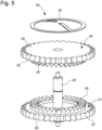
figure 5 représente schématiquement une vue en perspective éclatée du dispositif de remontage débrayable selon le mode de réalisation de l'invention de lafigure 1 . - Les
figures 1 à 5 représentent un mode de réalisation d'un dispositif de remontage 10, ici d'un barillet 2 d'horlogerie, selon l'invention. - Le dispositif de remontage 10 du barillet 2 comprend un rochet 3 et un rouage de remontage 40. Le rouage de remontage 40 engrène avec le rochet 3, de sorte que lorsque le rouage de remontage 40 est mis en rotation dans un premier sens, le rochet 3 est entraîné en rotation dans un deuxième sens inverse du premier sens.
- Le rochet 3 est monté solidaire sur un arbre de remontage, l'arbre de remontage permettant le remontage du barillet 2. L'arbre de remontage est de préférence cylindrique.
- Dans l'exemple, l'arbre de remontage est l'arbre de remontage du barillet 2, le rochet 3 étant agencé sur le barillet 2. Le rochet 3 comprend un moyeu 7 monté solidaire sur l'arbre de remontage.
- Dans une variante, non représentée sur les figures, l'arbre de remontage n'est pas monté sur le barillet, l'arbre de remontage comprenant un pignon engrenant avec un mobile entraînant l'arbre de remontage du barillet pour armer le ressort, si le rochet n'est pas monté sur le barillet.
- Le rouage de remontage 40 est agencé à côté du rochet 3, et s'étend de préférence dans le même plan que le rochet 3.
- Le rochet 3 comprend une première denture 11 externe répartie autour du rochet 3. La première denture 11 coopère avec une deuxième denture 22 périphérique agencée sur une première roue 28 du rouage de remontage 40. Le rouage de remontage 40 comprend une troisième denture 25 agencée sous la première roue.
- Le barillet 2 comporte un ressort spiral (non représenté sur les figures), agencé à l'intérieur du barillet 2, qui doit être armé, soit par un système de remontage automatique, soit par un système de remontage manuel.
- A cette fin, le dispositif de remontage 1 comprend en outre un système de rouages 23, par exemple entraîné par une masse de remontage automatique (non représentée sur les figures) du mouvement d'horlogerie. Le système de rouages 23 peut aussi être entraîné par une tige de remontoir (non représentée sur les figures) actionnable au moyen d'une couronne, dans la cas d'un remontage manuel.
- Un mobile d'actionnement 31 du remontage du système de rouages 23 actionne le rouage de remontage 40. Le mobile d'actionnement 31 comprend une deuxième roue 29 munie d'une quatrième denture 27 périphérique coopérant avec un autre mobile 32 du système de rouages 23. Le mobile d'actionnement 31 comprend une cinquième denture 24 agencée sur la deuxième roue 29, et engrenant avec la troisième denture 25 du rouage de remontage 40 en position embrayée.
- Ainsi, en actionnant le système de rouages 23, on applique un couple sur le rochet 3, qui le transmet au moins en partie à l'arbre de remontage, par l'intermédiaire du rouage de remontage 40 entraîné par le mobile d'actionnement 31.
- La rotation du mobile d'actionnement 31 et du rouage de remontage 40 engendre la rotation du rochet 3, et donc de l'arbre de remontage, lors du remontage du barillet 2.
- Pour éviter de sur-armer le barillet 2, le rouage de remontage 40 est mobile depuis une position embrayée dans laquelle il entraîne le rochet 3.
- Dans ce mode de réalisation, le dispositif de remontage débrayable 10 comprend un arbre rotatif 26, sur lequel le rouage de remontage 40 est monté coulissant atour dudit arbre rotatif 26. Le mobile d'actionnement 31 est monté solidaire sur l'arbre rotatif 26.
- Le rouage de remontage 40 engrène avec le mobile d'actionnement 31 du remontage, lorsqu'il est en position embrayée, et il n'engrène pas avec le mobile d'actionnement 31 du remontage, lorsqu'il coulisse le long de l'arbre rotatif 26.
- Ainsi, en position embrayée, le mobile d'actionnement 31 entraîne le rouage de remontage 40, et le rouage de remontage 40 entraîne le rochet 3.
- Tandis qu'après le coulissement du rouage de remontage 40, le mobile d'actionnement 31 tourne à vide et n'entraîne pas le rouage de remontage 40, qui est à distance du mobile d'actionnement 31. Ainsi, le rochet 3 n'est plus entraîné par le rouage de remontage 40.
- Le rouage de remontage 40 et le mobile d'actionnement 31 sont superposés, l'un au-dessus de l'autre. Le rouage de remontage 40 est agencé au-dessus du mobile d'actionnement 31, de sorte que la cinquième denture 24 du mobile d'actionnement 31 coopère avec la troisième denture 25 du rouage de remontage 40 en position embrayée.
- La troisième 25 et la cinquième denture 25 ont de préférence des dents en forme de dents de loups. Autrement dit, un côté de chaque dent est moins pentu que l'autre côté. Ainsi, les dentures peuvent glisser plus facilement l'une sur l'autre dans un sens de rotation préféré, si elles ne sont pas maintenues suffisamment pressées l'une contre l'autre.
- Le rouage de remontage 40 peut coulisser axialement selon l'axe de l'arbre rotatif 26. Ainsi, le rouage de remontage 40 peut effectuer un déplacement axial depuis la position embrayée, et réciproquement.
- En position embrayée, le rouage de remontage 40 et le mobile d'actionnement 31 sont en contact par la troisième 25 et la cinquième 24 denture, qui s'engrènent l'une avec l'autre. Ainsi, le mobile d'actionnement 31 entraîne le rouage de remontage 4, et donc le rochet 3.
- Tandis qu'en configuration débrayée, le rouage de remontage 40 et le mobile d'actionnement 31 sont plus éloignés l'un de l'autre, de sorte que la troisième 25 et la cinquième 24 denture ne s'engrènent entre elles. Ainsi, le mobile d'actionnement 31 n'entraîne pas le rouage de remontage 4, ni le rochet 3.
- En outre, la deuxième denture 22 du rouage de remontage 40 n'engrène plus avec la première denture 11 du rochet 3, lorsque le rouage de remontage 40 est débrayé. En effet, comme le rouage de remontage 40 a coulissé le long de l'arbre rotatif 26, la deuxième denture 22 s'est décalé au-delà de la première denture 11.
- Le dispositif de remontage 40 comprend en outre des moyens de rappel 50 exerçant une force de rappel axiale sur le rouage de remontage 40 en direction du mobile d'actionnement 31, pour le maintenir dans la position embrayée.
- Les moyens de rappel comportent un ressort (30) agencé au-dessus du rouage de remontage (40).
- Le rouage de remontage 40 est monté sur le ressort 30, qui exerce une force axiale sur le rouage de remontage 40 pour le maintenir dans la position embrayée.
- Le ressort 30 a une forme de collerette flexible assemblée à l'arbre rotatif 26, au-dessus du rouage de remontage 40. La collerette flexible est courbée ou repliée sur le rouage de remontage 40 pour appuyer dessus.
- La collerette flexible exerce une force de rappel axiale sur le rouage de remontage 40 en direction du mobile d'actionnement 31, de sorte que la troisième 25 et la cinquième 24 denture coopèrent en position embrayée.
- En outre, le rouage de remontage 40 coulisse autour de l'arbre de remontage 26, lorsque le couple appliqué sur le rouage de remontage 40 engendre une force axiale opposée et supérieure à la force exercée par les moyens de rappel 50.
- En effet, grâce à la forme des dents de loup des troisième 25 et cinquième 24 dentures, le couple appliqué sur le rouage de remontage 40 engendre une force repoussant le rouage de remontage 40 dans une direction opposée à la force produite par le ressort 30.
- Ainsi, lorsque le couple dépasse sensiblement une valeur seuil, le rouage de remontage 40 coulisse autour de l'arbre rotatif 26 pour sortir de la position embrayée. Le rouage de remontage 40 coulisse en effectuant un déplacement axial sensiblement rectiligne autour de l'arbre rotatif 26 depuis la position embrayée à une certaine distance du mobile d'actionnement 31.
- Au-delà de la valeur seuil, lorsque le couple demandé pour faire tourner le rochet 3 est plus élevé que celui demandé pour déplier la collerette flexible 26 vers le haut, le rouage de remontage 40 est poussé par le mobile d'actionnement 31 grâce à la troisième 25 et la cinquième 24 denture, en particulier grâce aux dentures 24, 25 en dents de loup.
- Autrement dit, lorsque le mobile d'actionnement 31 appuie fortement sur le rouage de remontage 40, la troisième 25 et la cinquième denture 24 en dent de loup glissent l'une sur l'autre sans s'engrener et le rouage de remontage 40 se déplace car la collerette flexible s'étend en remontant le long de l'arbre rotatif 26.
- Par conséquent, le mobile d'actionnement 31 continue de tourner, mais le rouage de remontage 40 et le rochet 3 ne tournent plus.
- Sur les
figures 1 et3 , en configuration de remontage, le couple de remontage exercé sur le rouage de remontage 40 par le mobile d'actionnement 31 est inférieur à la valeur seuil, de sorte que la collerette flexible ne change pas de forme. Ainsi, la première denture 12 et le rochet 3 sont entraînés par le rouage de remontage 40. - Sur les
figures 2 et4 , lorsque le barillet 2 est complètement armé, le couple de remontage exercé sur le rouage de remontage 40 par le mobile d'actionnement 31 est supérieur à la valeur seuil, de sorte que la collerette flexible se déplie et le rouage de remontage 40 se déplace vers le haut. Autrement dit, le couple demandé pour faire tourner le rochet 3 est trop important pour la collerette flexible, qui ne peut rester dans sa forme initiale. - Ces moyens de débrayage permettent de protéger le barillet 2 d'un sur-armage, et évite une usure prématurée à l'intérieur du barillet 2. On peut ainsi bloquer l'arbre de remontage lorsque le ressort du barillet est complètement armé, sans risquer de casser le ressort du barillet 2.
- Le barillet 2 comporte en outre une sixième denture 18 périphérique configurée pour coopérer avec une septième denture d'un mobile du mouvement d'horlogerie. Le mobile est par exemple une roue de moyenne. Une fois armé, le barillet 2 fournit l'énergie nécessaire au fonctionnement du mouvement d'horlogerie par l'intermédiaire du mobile.
- L'invention se rapporte également à un mouvement d'horlogerie, non représenté sur les figures, le mouvement comprenant un barillet et un dispositif de remontage du barillet tel que décrit précédemment.
- Naturellement, l'invention n'est pas limitée aux modes de réalisation décrits en référence aux figures et des variantes pourraient être envisagées sans sortir du cadre de l'invention.
Claims (10)
- Dispositif de remontage débrayable (10), notamment d'un barillet (2) doté d'un ressort, comprenant un rochet (3) monté solidaire sur un arbre de remontage, l'arbre de remontage étant par exemple un arbre de remontage du barillet (2) dont la rotation arme le barillet (2), et un rouage de remontage (40) engrenant avec le rochet (3), la rotation du rouage de remontage (40) entraînant la rotation du rochet (3) et celui de l'arbre de remontage, le dispositif de remontage (10) comprenant un mobile d'actionnement (31) pour entraîner le rouage de remontage (40) par application d'un couple sur le rouage de remontage (40), le mobile d'actionnement (31) engrenant avec le rouage de remontage (40) dans une position embrayée, le rouage de remontage (40) étant monté coulissant autour d'un arbre rotatif (26) pour pouvoir sortir de la position embrayée, lorsque le couple appliqué sur le rouage de remontage (40) est sensiblement supérieur à une valeur seuil, en particulier lorsque le barillet (2) est complètement armé.
- Dispositif de remontage selon la revendication 1, caractérisé en ce que le rouage de remontage (40) et le mobile d'actionnement (31) sont superposés en position embrayée.
- Dispositif de remontage selon la revendication 1 ou 2, caractérisé en ce que le mobile d'actionnement (31) est monté solidaire dudit arbre rotatif (26).
- Dispositif de remontage selon l'une, quelconque, des revendications précédentes, caractérisé en ce que le mobile d'actionnement (31) n'engrène pas avec le rouage de remontage (40), lorsque le rouage de remontage (4) coulisse.
- Dispositif de remontage selon l'une, quelconque, des revendications précédentes, caractérisé en ce qu'il comprend des moyens de rappel (50) exerçant une force de rappel axiale sur le rouage de remontage (40) en direction du mobile d'actionnement (31), pour le maintenir dans la position embrayée.
- Dispositif de remontage selon la revendication 5, dans lequel les moyens de rappel comportent un ressort (30) agencé au-dessus du rouage de remontage (40).
- Dispositif de remontage selon la revendication 5 ou 6, dans lequel le rouage de remontage (40) coulisse, lorsque le couple appliqué sur le rouage de remontage (40) engendre une force axiale opposée et supérieure à la force exercée par les moyens de rappel (50).
- Dispositif de remontage selon l'une, quelconque, des revendications précédentes, caractérisé en ce que le mobile d'actionnement (31) et le rouage de remontage (40) comportent chacun une denture (24, 25) en dents de loup, les deux dentures (24, 25) en dents de loup coopérant l'une avec l'autre.
- Dispositif de remontage selon la revendication 8, dans lequel le rouage de remontage (40) et le mobile d'actionnement (31) comprennent chacun une deuxième denture radiale (22, 27).
- Mouvement d'horlogerie comprenant un barillet (2) et un dispositif de remontage (10) du barillet (2) selon l'une, quelconque, des revendications précédentes.
Priority Applications (4)
| Application Number | Priority Date | Filing Date | Title |
|---|---|---|---|
| EP22210934.0A EP4379476A1 (fr) | 2022-12-01 | 2022-12-01 | Dispositif de remontage débrayable, notamment d'un barillet d'horlogerie, muni d'un rouage de remontage coulissant |
| US18/516,483 US20240184248A1 (en) | 2022-12-01 | 2023-11-21 | Disengageable winding device, in particular for a horological barrel, provided with a sliding winding gear train |
| CN202311559653.9A CN118131587A (zh) | 2022-12-01 | 2023-11-22 | 特别用于钟表发条盒的设有滑动上条轮系的上条装置 |
| JP2023198869A JP7671828B2 (ja) | 2022-12-01 | 2023-11-24 | 特に計時器用バレルのための、摺動式巻きギア列を備える係合解除可能な巻きデバイス |
Applications Claiming Priority (1)
| Application Number | Priority Date | Filing Date | Title |
|---|---|---|---|
| EP22210934.0A EP4379476A1 (fr) | 2022-12-01 | 2022-12-01 | Dispositif de remontage débrayable, notamment d'un barillet d'horlogerie, muni d'un rouage de remontage coulissant |
Publications (1)
| Publication Number | Publication Date |
|---|---|
| EP4379476A1 true EP4379476A1 (fr) | 2024-06-05 |
Family
ID=84370423
Family Applications (1)
| Application Number | Title | Priority Date | Filing Date |
|---|---|---|---|
| EP22210934.0A Pending EP4379476A1 (fr) | 2022-12-01 | 2022-12-01 | Dispositif de remontage débrayable, notamment d'un barillet d'horlogerie, muni d'un rouage de remontage coulissant |
Country Status (4)
| Country | Link |
|---|---|
| US (1) | US20240184248A1 (fr) |
| EP (1) | EP4379476A1 (fr) |
| JP (1) | JP7671828B2 (fr) |
| CN (1) | CN118131587A (fr) |
Citations (2)
| Publication number | Priority date | Publication date | Assignee | Title |
|---|---|---|---|---|
| FR1207713A (fr) * | 1957-08-20 | 1960-02-18 | Otero | Mécanisme de remontage automatique, notamment pour montres-bracelets |
| US3878673A (en) * | 1973-01-20 | 1975-04-22 | Bifora Uhren | Automatic watch |
Family Cites Families (2)
| Publication number | Priority date | Publication date | Assignee | Title |
|---|---|---|---|---|
| EP1845425B1 (fr) | 2006-04-12 | 2011-07-13 | Montres Breguet S.A. | Pièce d'horlogerie à sonnerie comportant un seul barillet |
| CH702924B1 (fr) | 2010-06-03 | 2011-10-14 | Patek Philippe Sa Geneve | Mobile à embrayage unidirectionnel, mécanisme de remontage et pièce d'horlogerie comportant ledit mobile. |
-
2022
- 2022-12-01 EP EP22210934.0A patent/EP4379476A1/fr active Pending
-
2023
- 2023-11-21 US US18/516,483 patent/US20240184248A1/en active Pending
- 2023-11-22 CN CN202311559653.9A patent/CN118131587A/zh active Pending
- 2023-11-24 JP JP2023198869A patent/JP7671828B2/ja active Active
Patent Citations (2)
| Publication number | Priority date | Publication date | Assignee | Title |
|---|---|---|---|---|
| FR1207713A (fr) * | 1957-08-20 | 1960-02-18 | Otero | Mécanisme de remontage automatique, notamment pour montres-bracelets |
| US3878673A (en) * | 1973-01-20 | 1975-04-22 | Bifora Uhren | Automatic watch |
Also Published As
| Publication number | Publication date |
|---|---|
| US20240184248A1 (en) | 2024-06-06 |
| CN118131587A (zh) | 2024-06-04 |
| JP2024080641A (ja) | 2024-06-13 |
| JP7671828B2 (ja) | 2025-05-02 |
Similar Documents
| Publication | Publication Date | Title |
|---|---|---|
| EP2350745B1 (fr) | Organe moteur pour mouvement horloger | |
| EP1404968B1 (fr) | Demarreur pour vehicule automobile | |
| EP1528443B1 (fr) | Dispositif de force constante pour une montre | |
| EP0881652A1 (fr) | Mécanisme d'entrainement à ressort pour un appareil de commutation, en particulier un disjoncteur | |
| FR2984433A1 (fr) | Embrayage a rattrapage d'usure, notamment pour vehicule automobile | |
| FR2809147A1 (fr) | Embrayage a friction a dispositif de rattrapage de jeu pilote pour vehicule automobile | |
| EP3220206A1 (fr) | Dispositif horloger de transmission | |
| EP1978419B1 (fr) | Dispositif de remontage comprenant un accouplement à sens unique | |
| EP2735919B1 (fr) | Mouvement de montre comportant une fusée | |
| CH720292A2 (fr) | Dispositif de remontage débrayable, notamment d'un barillet d'horlogerie, muni d'un rouage de remontage coulissant | |
| EP4379475A1 (fr) | Dispositif de remontage, notamment d'un barillet d' horlogerie, muni d'un rouage de remontage debrayable | |
| CH720293A2 (fr) | Dispositif de remontage, notamment d'un barillet d'horlogerie, muni d'un rouage de remontage débrayable | |
| EP4375756A1 (fr) | Dispositif de remontage, notamment d'un barillet d'horlogerie, muni d'un rochet débrayable | |
| CH720260A2 (fr) | Dispositif de remontage, notamment d'un barillet d'horlogerie, muni d'un rochet débrayable | |
| EP4375757B1 (fr) | Dispositif de remontage d'un barillet d horlogerie, muni de moyens de débrayage | |
| EP2244138B1 (fr) | Dispositif de remontage d'une montre automatique comportant un système de débrayage | |
| CH720258A2 (fr) | Dispositif de remontage, notamment d'un barillet d'horlogerie, muni de moyens de débrayage | |
| CH707271A2 (fr) | Mouvement de montre comportant une fusée. | |
| EP1119707B1 (fr) | Demarreur de vehicule automobile du type a entrainement par friction | |
| EP4075204A1 (fr) | Cliquet d'arret pour mouvement d'horlogerie | |
| EP3686694B1 (fr) | Mécanisme de réveil et pièce d'horlogerie comportant un tel mécanisme | |
| EP4513274A1 (fr) | Mouvement horloger | |
| EP1461528B1 (fr) | Demareur electrique de vehicule automobile equipe d un lance ur a cannelures perfectionnees | |
| WO2017207917A1 (fr) | Actionneur pour un embrayage, notamment de vehicule automobile | |
| FR3136266A3 (fr) | Dispositif et procédé d’embrayage unidirectionnel |
Legal Events
| Date | Code | Title | Description |
|---|---|---|---|
| PUAI | Public reference made under article 153(3) epc to a published international application that has entered the european phase |
Free format text: ORIGINAL CODE: 0009012 |
|
| STAA | Information on the status of an ep patent application or granted ep patent |
Free format text: STATUS: THE APPLICATION HAS BEEN PUBLISHED |
|
| AK | Designated contracting states |
Kind code of ref document: A1 Designated state(s): AL AT BE BG CH CY CZ DE DK EE ES FI FR GB GR HR HU IE IS IT LI LT LU LV MC ME MK MT NL NO PL PT RO RS SE SI SK SM TR |
|
| P01 | Opt-out of the competence of the unified patent court (upc) registered |
Free format text: CASE NUMBER: APP_50336/2024 Effective date: 20240905 |
|
| STAA | Information on the status of an ep patent application or granted ep patent |
Free format text: STATUS: REQUEST FOR EXAMINATION WAS MADE |
|
| 17P | Request for examination filed |
Effective date: 20241202 |
|
| RBV | Designated contracting states (corrected) |
Designated state(s): AL AT BE BG CH CY CZ DE DK EE ES FI FR GB GR HR HU IE IS IT LI LT LU LV MC ME MK MT NL NO PL PT RO RS SE SI SK SM TR |
|
| GRAP | Despatch of communication of intention to grant a patent |
Free format text: ORIGINAL CODE: EPIDOSNIGR1 |
|
| STAA | Information on the status of an ep patent application or granted ep patent |
Free format text: STATUS: GRANT OF PATENT IS INTENDED |
|
| INTG | Intention to grant announced |
Effective date: 20260212 |