EP4379351A1 - Systems and methods for optical particle detection - Google Patents
Systems and methods for optical particle detection Download PDFInfo
- Publication number
- EP4379351A1 EP4379351A1 EP23212060.0A EP23212060A EP4379351A1 EP 4379351 A1 EP4379351 A1 EP 4379351A1 EP 23212060 A EP23212060 A EP 23212060A EP 4379351 A1 EP4379351 A1 EP 4379351A1
- Authority
- EP
- European Patent Office
- Prior art keywords
- chamber
- light
- particle
- velocity
- openings
- Prior art date
- Legal status (The legal status is an assumption and is not a legal conclusion. Google has not performed a legal analysis and makes no representation as to the accuracy of the status listed.)
- Pending
Links
Images




Classifications
-
- G—PHYSICS
- G01—MEASURING; TESTING
- G01N—INVESTIGATING OR ANALYSING MATERIALS BY DETERMINING THEIR CHEMICAL OR PHYSICAL PROPERTIES
- G01N15/00—Investigating characteristics of particles; Investigating permeability, pore-volume or surface-area of porous materials
- G01N15/10—Investigating individual particles
- G01N15/14—Optical investigation techniques, e.g. flow cytometry
- G01N15/1434—Optical arrangements
-
- G—PHYSICS
- G01—MEASURING; TESTING
- G01N—INVESTIGATING OR ANALYSING MATERIALS BY DETERMINING THEIR CHEMICAL OR PHYSICAL PROPERTIES
- G01N15/00—Investigating characteristics of particles; Investigating permeability, pore-volume or surface-area of porous materials
- G01N15/10—Investigating individual particles
- G01N15/14—Optical investigation techniques, e.g. flow cytometry
- G01N15/1456—Optical investigation techniques, e.g. flow cytometry without spatial resolution of the texture or inner structure of the particle, e.g. processing of pulse signals
- G01N15/1459—Optical investigation techniques, e.g. flow cytometry without spatial resolution of the texture or inner structure of the particle, e.g. processing of pulse signals the analysis being performed on a sample stream
-
- G—PHYSICS
- G01—MEASURING; TESTING
- G01N—INVESTIGATING OR ANALYSING MATERIALS BY DETERMINING THEIR CHEMICAL OR PHYSICAL PROPERTIES
- G01N15/00—Investigating characteristics of particles; Investigating permeability, pore-volume or surface-area of porous materials
- G01N2015/0023—Investigating dispersion of liquids
- G01N2015/003—Investigating dispersion of liquids in liquids, e.g. emulsion
-
- G—PHYSICS
- G01—MEASURING; TESTING
- G01N—INVESTIGATING OR ANALYSING MATERIALS BY DETERMINING THEIR CHEMICAL OR PHYSICAL PROPERTIES
- G01N15/00—Investigating characteristics of particles; Investigating permeability, pore-volume or surface-area of porous materials
- G01N2015/0042—Investigating dispersion of solids
- G01N2015/0053—Investigating dispersion of solids in liquids, e.g. trouble
-
- G—PHYSICS
- G01—MEASURING; TESTING
- G01N—INVESTIGATING OR ANALYSING MATERIALS BY DETERMINING THEIR CHEMICAL OR PHYSICAL PROPERTIES
- G01N15/00—Investigating characteristics of particles; Investigating permeability, pore-volume or surface-area of porous materials
- G01N15/10—Investigating individual particles
- G01N2015/1027—Determining speed or velocity of a particle
-
- G—PHYSICS
- G01—MEASURING; TESTING
- G01N—INVESTIGATING OR ANALYSING MATERIALS BY DETERMINING THEIR CHEMICAL OR PHYSICAL PROPERTIES
- G01N15/00—Investigating characteristics of particles; Investigating permeability, pore-volume or surface-area of porous materials
- G01N15/10—Investigating individual particles
- G01N15/14—Optical investigation techniques, e.g. flow cytometry
- G01N15/1434—Optical arrangements
- G01N2015/1447—Spatial selection
-
- G—PHYSICS
- G01—MEASURING; TESTING
- G01N—INVESTIGATING OR ANALYSING MATERIALS BY DETERMINING THEIR CHEMICAL OR PHYSICAL PROPERTIES
- G01N15/00—Investigating characteristics of particles; Investigating permeability, pore-volume or surface-area of porous materials
- G01N15/10—Investigating individual particles
- G01N15/14—Optical investigation techniques, e.g. flow cytometry
- G01N2015/1493—Particle size
Definitions
- Examples of the present disclosure generally relates to debris or particle detection systems, including liquid debris or particle detection systems that may include a fiber optic sensor and which may be used to detect metals and non-metals.
- the technology relates to a particle detection system including a light source configured to generate a light beam, a first collimator lens outside a chamber and configured to channel the generated light beam from the light source into the chamber through a first sidewall of the chamber, the chamber being configured to hold fluid therein and including a plurality of openings on a second sidewall thereof, the second sidewall being opposite the first sidewall, and a second collimator lens on an opposite side of the chamber from the first collimator lens, the second collimator lens being configured to channel light received from the plurality of openings to a light detector.
- the first sidewall is transparent to the generated light beam, and the second sidewall is opaque to the generated light beam.
- the system further includes a controller configured to control the light generator and the light detector, wherein the controller and the plurality of openings constitute one or more velocity measurement systems.
- the plurality of openings include one or more pairs of openings, and each velocity measurement system includes one pair of openings including an upper opening and a lower opening.
- the controller is configured to measure a timing of passage of one or more particles flowing through the chamber based on a detected light transmitted through one of the pairs of openings.
- the one or more velocity measurement systems include a first velocity measurement system including a first upper opening and a first lower opening, and a second velocity measurement system including a second upper opening and a second lower opening.
- the controller is configured to measure a first velocity of the particle at the first velocity measurement system and a second velocity of the particle at the second velocity measurement system.
- the controller is configured to determine a size of the one or more particles based on a comparison of the first velocity and the second velocity.
- the system further includes one or more sensors configured to measure a fluid flow through the chamber, wherein the controller is coupled to the one or more sensors.
- at least one of the light source and the light detector includes a fiber optic cable, the fiber optic cable including one of a single optical fiber and a plurality of optical fibers.
- each of the light source and the light detector includes one of an LED, a photo sensor, and a fiber optic cable.
- the system further includes a receptable configured to collect the particles flowing through the chamber, the receptable being located downstream from the chamber in a direction of the particle.
- the technology in another aspect, relates to a method for detecting one or more particles flowing through a chamber, the method including generating a light beam at a light source, channeling the generated light beam into the chamber via a first collimator lens outside a first sidewall of the chamber, detecting light escaped from the chamber via a plurality of openings, the plurality of openings being formed at a second sidewall of the chamber opposite the first sidewall, at a light detector via a second collimator lens located outside the second sidewall, and determining one or more parameters of the one or more particles flowing through the chamber based on the received escaped light.
- detecting the escaped light via the plurality of openings includes receiving the escaped light via a plurality of pairs of openings. In other examples, detecting the escaped light via the plurality of openings includes receiving the escaped light via one of one pair of openings and two pairs of openings. In further examples, detecting the escaped light includes receiving the escaped light via a first pair of openings including a first upper opening and a first lower opening, and via a second pair of openings including a second upper opening and a second lower opening. In addition examples, determining the one or more parameters includes determining one or more of a size of the one or more particles, and a type of material of the one or more particles. In further examples, determining the one or more parameters includes determining a velocity of a particle based on determined a timing of the particle between openings of one of the pairs of openings.
- generating the light beam at the light source includes generating the light beam at one of a first fiber optic cable, a first LED, and a first photo sensor
- detecting the light escaped from the chamber includes detecting the escaped light at a second fiber optic cable, a second LED, and a second photo sensor.
- channeling the generated light beam into the chamber includes channeling the generated light beam through a first transparent sidewall of the chamber.
- detecting the light escaped from the chamber includes detecting the light escaped from a second opaque sidewall of the chamber, the second opaque sidewall including the plurality of openings.
- the method further includes collecting the one or more particles that flowed through the chamber in a receptable.
- Debris monitoring systems can, for example, be used to detect the presence of wear particles in lubricating oils that may be transferred from, e.g., oil-wetted surfaces of gears and bearings under mechanical stress.
- Automatic debris monitoring is often preferred from a maintenance perspective, as debris monitoring may eliminate the need for certain routine inspections, and may preempt potential failure should a crack or other failure deteriorate faster than an inspection interval.
- the aerospace industry is trending towards "on-condition" maintenance, which means that the Line Replaceable Unit (LRU) may not require routine maintenance or inspections, and may preferably fail in a "soft" manner (i.e., the LRU will signal when it needs calibration or service, while maintaining some level of degraded operability).
- LRU Line Replaceable Unit
- Capturing monitors or sensors may, for example, employ a high-strength magnet to attract ferrous particles and detects particles via inductive principles. The particles can then be inspected and further tested to determine if they are representative of gear or bearing steel, or if they are nuisance debris.
- a potential challenge with capturing type sensors is that the build-up of particles may affect the accuracy of size discrimination and eventually the sensor could become "saturated" and unresponsive to additional particle captures, and may therefore require routine maintenance.
- Flow-through debris monitors generally work on the principle of induction and may respond to both ferrous and non-ferrous debris. Since flow-through debris monitors do not capture particles they generally do not require routine maintenance. However, particle inspections are not necessarily a feature or capability.
- hybrid bearings e.g., steel races with ceramic rolling elements
- DN velocity bearing diameter multiplied by the operating velocity
- temperature operation higher temperature operation
- centrifugal forces due to lighter weight
- hybrid bearings may, among other things, require a viable technology that may need to be approved for various applications such as, e.g., flight applications, and that can detect non-metals. Accordingly, there is a technical problem in determining an appropriate debris monitoring technique for hybrid bearings and hybrid systems. Consequently, there is a need for solutions/options that address one or more of the aforementioned challenges.
- the foregoing discussion is intended only to illustrate examples of the present field and should not be taken as a disavowal of scope.
- a technical solution to the above technical problem includes the use of optical techniques to detect the presence of particles, as well to determine their respective sizes and material types.
- FIGS. 1A-1C are schematic views of a particle detection system, according to examples of the present disclosure.
- FIG. 1A generally illustrates a debris detection system, or debris detector, 10 according to examples of the present disclosure.
- the debris detection system 10 may be used in various mechanical-fluid configurations, such as, e.g., a gearbox for various vehicles.
- the debris detection system 10 may include a chamber 20.
- the chamber 20 may include a first sidewall 22 that is transparent to light, and a second sidewall 24, opposite the first sidewall 22, that is opaque to light but that includes a plurality of openings 92 and 94.
- the chamber 20 may be a flow-through chamber, where the particles 30 flow therethrough, and may be configured to hold a fluid therein, the fluid including the particles 30 flowing from one end of the chamber 20 such as, e.g., a top end, to another end of the chamber 20 such as, e.g., a bottom end thereof under the driving force of, e.g., gravity.
- the system 10 may include one or more optical fibers 40, and collimator lenses 60 and 70.
- a first collimator lens 60 is configured to channel a light beam 65 generated from a light source 45 and provided through an optical fiber 40 into the chamber 20.
- a second collimator lens 70 is configured to channel light escaping from chamber 20 via, e.g., the openings 92 and 94, to a light receiver 48 through another optical fiber 42.
- the system 10 may include the plurality of openings 92 and 94 through which light that entered the chamber 20 can escape therethrough and transmit onto the light receiver 48 via the second collimator lens 70 and the optic cable 42.
- examples of the present disclosure may be provided without a prism.
- a debris particle 30 held in the fluid (not shown) and passing through the chamber 20 may block a light path between the chamber 20 and the second collimator 70, and may alternatively block light and allow light to pass through the openings 92 and 94 as it travels downward.
- debris size may be detected by the system, for example, by measuring the light transmitted through the chamber 20 by measuring the light signal amplitude that is blocked by the particulate 30.
- the amplitude of the light signal escaping from the chamber 20 onto the collimator lens 70 is proportional to the amount of light that is blocked by the particle 30.
- a 100% amplitude means that no light is blocked by the particle 30, and that the particle 30 has thus passed by the corresponding opening 92 or 94.
- an amplitude of, e.g., 30% means that only 30% of the light that would have been transmitted to an opening had the particle 30 not been present is being transmitted due to the blocking presence of the particle 30 in front of the opening 92 or 94.
- the existence of particles and attributes thereof such as, e.g., particle size, may be detected without regard to the particle's inherent material composition.
- changes in light transmitted to the second collimator lens 70 may be correlated to aspects or attributes associated with one or more of the particles 30.
- the particle 30 travels through the chamber 20 from a top end thereof to a bottom end thereof, e.g., under the driving force of gravity, and as the particle passes in front of the first opening 92, progressively blocks the light and progressively prevents the light from escaping through the first opening 92 until it completely blocks the light form escaping through the first opening 92.
- the particle 30 may pass by the first opening 92, no longer blocking the light therethrough, and may then pass in front of the second opening 94, thereby progressively blocking the light and progressively preventing the light from escaping through the opening 94 at it progresses downwards.
- the time that the particle takes to pass through by openings 92 and 94 may provide sufficient information to determine the velocity of the particle flowing through the fluid present in the chamber 20.
- the velocity of the particle may be measured as the distance between each opening 92 and 94 divided by the amount of time taken by the particle to travel that distance, as further discussed below with respect to the description of FIG. 1C .
- the system 10 may also include a receptable 80 located under the chamber 20 and configured to collect the particles 30 after they flow through the chamber 20.
- the particles 30 that are collected at the receptable 80 may be analyzed, inspected and further tested to determine, e.g., if they are representative of gear or bearing steel, or if they are nuisance debris.
- the chamber 20, light generator 45 and light receiver 48 may be coupled to a processor 85 similar to the processors and controllers further discussed below with respect to FIG. 7 .
- FIG. 1B illustrates a chamber 20' that may be part of a particle detection system such as system 10 discussed above with respect to FIG. 1A .
- the chamber 20' includes, in addition to a first pair of openings 92 and 94, a second pair of openings 92' and 94'.
- the particle 30 travels through the chamber 20 from a top end thereof to a bottom end thereof, e.g., under the driving force of gravity, and as the particle passes in front of the first opening 92, progressively blocks the light and progressively prevents the light from escaping through the first opening 92.
- the particle 30 may pass by the first opening 92, no longer blocking the light therethrough, and pass in front of the second opening 94, thereby also progressively blocking the light and progressively preventing the light from escaping through the opening 94.
- the particle 30 continues to travel through the chamber 20 e.g., under the driving force of gravity, below both openings 92 and 94 and in front of opening 92'. For example, the particle passes in front of the first opening 92', progressively blocks the light and progressively prevents the light from escaping through the first opening 92'.
- the particle 30 may pass by the first opening 92', no longer blocking the light therethrough, and pass in front of the second opening 94', thereby progressively blocking the light and progressively preventing the light from escaping through the opening 94'.
- various parameters relative to the particle such as, e.g., the velocity of the particle and the size of the particle.
- additional parameters relative to the particle 30 may be derived such as, e.g., the type of material, or the density of the particle 30, as discussed in greater detail below with respect to the description of FIG. 5 .
- FIG. 1C illustrates a path of a particle 30 as it travels through the chamber 20, in various examples, as well as various types of information that may be determined based on the timing of travel of the particle 30 along the direction 50 from a top portion to a bottom portion of the chamber 20.
- the leading edge 34 of the particle 30 may pass in front of the first opening 92 and progressively block the light passing therethrough. Accordingly, for a period of time, as the leading edge 34 of the particle 30 travels the distance "h" corresponding to the size of the opening 92, light is progressively blocked until no light passes through the opening 92.
- the period between the time at which the leading edge 34 of the particle 30 reaches the beginning of the opening 92 and the time at which the trailing edge 32 of the particle 30 leaves the end of the opening 92, which constitutes a period during which no light passes through the opening 92, may be measured.
- another period may be measured between the time where the leading edge 34 reaches the end of the opening 92 and the time at which the leading edge 34 reaches the end of the second opening 94, which corresponds to the distance "H" between the first opening 92 and the second opening 94.
- the time at which the leading edge 34 reaches the end of the opening 92 may be indicated by the time at which a total blocking of the light passing through the opening 92, e.g., 0% of the light passes through the opening 92.
- the time at which the leading edge 34 reaches the end of the second opening 94 may also be determined as the time at which the light passing through the second opening 94 is also blocked, e.g., 0% of the light passes through the opening 94.
- the distance between the end of the first opening 92 and the end of the second opening 94 is known as "H.”
- V is the velocity
- H is the distance between the end of the first opening 92 and the end of the second opening 94
- T LE is the time it takes for the leading edge 34 of the particle 30 to travel between the end of the first opening 92 and the end of the second opening 94.
- Equation (2) L is the length of the particle in the direction 50, V is the velocity as, e.g., calculated via Equation (1) above, and "T" is the period of time between the time at which the leading edge 34 of the particle 30 reaches the end of the first opening 92 and the time at which the trailing edge 32 of the particle 30 leaves the end of the first opening 92.
- the length of the particle L corresponds to the diameter of the particle.
- the time at which the leading edge 34 of the particle 30 reaches the end of the first opening 92 may be determined as the time at which the light transmitted through the first opening 92 is completely blocked, or in other words that the signal amplitude is equal to 0% of what it was prior to the particle 30 entering the chamber 20.
- the time at which the trailing edge 32 of the particle 30 leaves the end of the first opening 92 is the time at which the signal amplitude of the light transmitted through the first opening 92 is back to being equal to 100% of what it was prior to the particle 30 entering the chamber 20. Accordingly, by calculating the period of time "T" as discussed above, it is possible to estimate the size, or length "L,” of the particle 30 in the direction 50.
- Equations (1) and (2) may be performed for each pair of openings 92/94 and 92'/94'. Performing the same calculation for both pairs of openings may allow to determine a terminal velocity of the particle when the velocity calculated for the first pair of openings 92/94 is equal to the velocity calculated for the second pair of openings 92'/94'. Such calculation may also provide a level of redundancy in calculating the size of the particle based on Equations (1) and (2) above.
- FIG. 2 is a look-up table that can be used to determine a type of material of the flowing particles 30, according to examples of the disclosure.
- the table illustrated in FIG. 2 represents a material discrimination algorithm based on trop testing data of, e.g., ferrous and ceramic debris particles, at elevated temperatures.
- the material discrimination algorithm is based on the temperature of the fluid, the velocity of the particles, and the amplitude or amount of light that is blocked by the particle 30 when passing in front of openings 92/94 or 92'/94'.
- the larger the particle the higher the attenuation of light escaping through the openings 92/94 or 92'/94'.
- Equation (3) for each temperature T, y is the computed velocity of the particle, and A is the measured 30% amplitude, or the amount of light when 30% of the opening 92/94 is blocked by the particle 30.
- y is the computed velocity of the particle
- A is the measured 30% amplitude, or the amount of light when 30% of the opening 92/94 is blocked by the particle 30.
- amplitude sizing may be used.
- amplitude sizing is the determination of the type of material of the particle by taking into account the size of the particle and the velocity of the particle.
- the particle when a particle is small and the velocity thereof is large, it may be deduced that the particle is a heavy particle and is likely to have a higher density such as, e.g., steel, silver, lead, or other high-density metal.
- the material of the particle if the particle is large and the velocity thereof is low, then it may be deduced that the material of the particle has a low density and may be, e.g., a ceramic, polyether ether ketone (PEEK), or aluminum.
- PEEK polyether ether ketone
- the temperature T is between 75°C and 90°C, then if the velocity V is greater than the measured velocity "y," the type of material of the particle is metal. If the velocity V is equal to or smaller than the measured velocity "y,” then the type of material of the particle is ceramic.
- the temperature T is equal to 90° or more and lower than 110°
- the velocity V is greater than the measured velocity "y”
- the type of material of the particle is metal. If the velocity V is equal to or smaller than the measured velocity "y,” then the type of material of the particle is ceramic.
- the temperature T is equal to 110°C or more and lower than 130°C
- the velocity V is greater than the measured velocity "y”
- the type of material of the particle is metal. If the velocity V is equal to or smaller than the measured velocity "y,” then the type of material of the particle is ceramic.
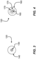
- FIGS. 3 and 4 are cross-sectional views generally illustrating examples of a single fiber configuration and a multiple fiber configuration, respectively.
- FIG. 3 generally illustrates an example of a single fiber configuration, or single fiber optic cable 120.
- the single fiber configuration/cable 120 may include a single optical fiber 130 and a fiber supporting structure or structural member 140.
- the single optical fiber 130 may include an emitter or a detector based on whether the optical fiber 130 is an emitting optical fiber such as, e.g., the light emitter 40/45 discussed above with respect to FIG. 1A , or a light receiver such, e.g., the light receiver 42/48 discussed above with respect to FIG. 1A .
- FIG. 4 generally illustrates an example of a multiple fiber configuration, or multiple fiber cable 150.
- the multiple fiber optic configuration, or multiple fiber optic cable 150 may include a first optical fiber (e.g., light emitter or light receiver) 160, a plurality of second optical fibers (e.g., light emitters or light detectors) 170, and a fiber supporting structure (or structural member) 180.
- the first optical fiber 160 may include a central optical fiber that may be configured to be a light emitter or light receiver
- the second optical fibers 170 may include light detectors or light emitters and may be arranged or clustered about the first optical fiber 160 (e.g., in a planetary arrangement).
- the fiber supporting structure 180 may encase both a first optical fiber 160 and a plurality of second optical fibers 170.
- a single cable whether having a single fiber (e.g., single fiber optic cable 120) or a multiple fibers (e.g., multiple fiber optic cable 150), may be employed.
- the multiple fiber cable 150 may include light emitters or lights detectors based on whether the multiple fiber cable 150 is an emitting optical device such as, e.g., the light emitter 40/45 discussed above with respect to FIG. 1A , or a light receiving device such, e.g., the light receiver 42/48 discussed above with respect to FIG. 1A .
- Examples of debris detection systems such as disclosed may provide various advantages. For example and without limitation, such systems: (a) may function in an "on-condition” mode and may be employed "in-line” or in an active/constant fluid stream; (b) may provide independence from debris material or composition (e.g., making it irrelevant if the particle or debris material is comprised of a metal or non-metal (such as, without limitation, a ceramic)); (c) may provide independence (e.g., inherent independence) from temperature; (d) may provide or permit high temperature functionality and capabilities; (e) may be used in conjunction with cyclonic or other forms of separators (e.g., as a supplemental system); and/or may have a single fiber or multiple fiber configuration.
- a metal or non-metal such as, without limitation, a ceramic
- FIG. 5 is a representation of an example of a cyclonic debris separator system configuration.
- FIG. 5 is a representation of an example of a cyclonic debris separator system 500 and is described, e.g., in U.S. Patent No. 7,288,139 , which is incorporated herein by reference in its entirety.
- a mixture of materials to be separated is introduced in the debris separator 500 via inlet 510, and thereafter flows in a helical vortex that spirals downward through the separator 500 through a debris passage 520 and into a chamber 20 such as, e.g., the chamber 20 discussed above with respect to FIG. 1A .
- the separated particles 30 may travel through the chamber 20 from a top portion thereof to a bottom portion thereof.
- the particles 30 may pass in front of a light emitting system 62.
- the light emitting system 62 may include a light source and a collimator lens such as, e.g., the light source 45 including the optical fiber 40 and the collimator lens 60 illustrated above with respect to FIG. 1A .
- the cyclonic debris separator 500 also includes a light receiving system 64.
- the light reciting system 64 may include a light receiver and a collimator lens such as, e.g., the light receiver 48 including the optical fiber 42 and the collimator lens 70 illustrated above with respect to FIG. 1A .
- the particles 30 may be collected at a receptable such as, e.g., the receptable 80 illustrated above with respect to FIG. 1A .
- FIG. 6 is a flow chart illustrating a method for detecting one or more particles flowing through a chamber, according to various examples of the disclosure.
- the method 600 includes operation 610, during which a light beam is generated at a light source.
- generating the light beam at the light source may include generating the light beam at one of a first fiber optic cable, a first LED, and a first photo sensor.
- operation 610 includes generating the light beam 65 at the light source 45 via optical fiber 40.
- operation 620 includes channeling the light beam into a chamber, e.g., via a first collimator lens located outside a sidewall of the chamber.
- channeling the generated light beam into the chamber may include channeling the generated light beam through a transparent sidewall of the chamber.
- operation 620 includes channeling the light beam 65 into chamber 20 via collimator lens 60 located outside sidewall 22 of the chamber 20.
- operation 630 includes detecting light that escaped from the chamber via, e.g., a plurality of openings formed at another sidewall of the chamber that is opposite from the transparent sidewall through which the light entered the chamber.
- the other sidewall is an opaque sidewall and the light escapes from the chamber via the openings formed in the opaque sidewall.
- the escaped light from the chamber may be detected after passing through a second collimator lens located outside the chamber on an opposite side of the chamber from the first collimator lens.
- detecting the escaped light via the plurality of openings may include receiving the escaped light via a plurality of pairs of openings, and in other examples detecting the escaped light via the plurality of openings may include receiving the escaped light via a one or two pairs of openings.
- detecting the escaped light may include receiving the escaped light via a first pair of openings including a first upper opening and a first lower opening, and via a second pair of openings including a second upper opening and a second lower opening.
- detecting the light escaped from the chamber may include detecting the escaped light at a second fiber optic cable, a second LED, and a second photo sensor.
- operation 630 includes detecting light that escaped from the chamber 20 via openings 92 and 94 formed at sidewall 24 of the chamber 20.
- operation 640 includes determining one or more parameters of the one or more particles flowing through the chamber based on the received escaped light using, e.g., any one of Equations (1)-(3).
- determining the one or more parameters may include determining a size of the one or more particles, or a type of material of the one or more particles.
- determining the one or more parameters may include determining a velocity of a particle based on determined a timing of the particle between openings of one of the pairs of openings.
- operation 640 may further include determining a length of the particle based on Equation (2) discussed above.
- the one or more particles that flow through the chamber may be collected at, e.g., a receptacle.
- the collected particles may be further analyzed, inspected and further tested to determine, e.g., if they are representative of gear or bearing steel, or if they are nuisance debris.
- FIG. 7 depicts one example of a suitable operating environment 700 in which one or more of the present examples can be implemented.
- This operating environment may be incorporated directly into the controller for a mass spectrometry or other mass analysis system, e.g., such as the controller 85 depicted in FIG. 1A .
- operating environment 700 typically includes at least one processing unit 702 and memory 704.
- memory 704 can be volatile (such as RAM), non-volatile (such as ROM, flash memory, etc.), or some combination of the two.
- This most basic configuration is illustrated in FIG. 7 by dashed line 706.
- environment 700 can also include storage devices (removable, 708, and/or non-removable, 710) including, but not limited to, magnetic or optical disks or tape.
- environment 700 can also have input device(s) 714 such as touch screens, keyboard, mouse, pen, voice input, etc., and/or output device(s) 716 such as a display, speakers, printer, etc. Also included in the environment can be one or more communication connections 712, such as LAN, WAN, point to point, Bluetooth, RF, etc.
- input device(s) 714 such as touch screens, keyboard, mouse, pen, voice input, etc.
- output device(s) 716 such as a display, speakers, printer, etc.
- communication connections 712 such as LAN, WAN, point to point, Bluetooth, RF, etc.
- Operating environment 700 typically includes at least some form of computer readable media.
- Computer readable media can be any available media that can be accessed by processing unit 702 or other devices having the operating environment.
- Computer readable media can include computer storage media and communication media.
- Computer storage media includes volatile and nonvolatile, removable and non-removable media implemented in any method or technology for storage of information such as computer readable instructions, data structures, program modules or other data.
- Computer storage media includes, RAM, ROM, EEPROM, flash memory or other memory technology, CD-ROM, digital versatile disks (DVD) or other optical storage, magnetic cassettes, magnetic tape, magnetic disk storage or other magnetic storage devices, solid state storage, or any other tangible medium which can be used to store the desired information.
- Communication media embodies computer readable instructions, data structures, program modules, or other data in a modulated data signal such as a carrier wave or other transport mechanism and includes any information delivery media.
- modulated data signal means a signal that has one or more of its characteristics set or changed in such a manner as to encode information in the signal.
- communication media includes wired media such as a wired network or direct-wired connection, and wireless media such as acoustic, RF, infrared and other wireless media. Combinations of the any of the above should also be included within the scope of computer readable media.
- a computer-readable device is a hardware device incorporating computer storage media.
- the operating environment 700 can be a single computer operating in a networked environment using logical connections to one or more remote computers.
- the remote computer can be a personal computer, a server, a router, a network PC, a peer device or other common network node, and typically includes many or all of the elements described above as well as others not so mentioned.
- the logical connections can include any method supported by available communications media.
- Such networking environments are commonplace in offices, enterprise-wide computer networks, intranets and the Internet.
- the components described herein include such modules or instructions executable by computer system 700 that can be stored on computer storage medium and other tangible mediums and transmitted in communication media.
- Computer storage media includes volatile and non-volatile, removable and non- removable media implemented in any method or technology for storage of information such as computer readable instructions, data structures, program modules, or other data. Combinations of any of the above should also be included within the scope of readable media.
- computer system 700 is part of a network that stores data in remote storage media for use by the computer system 700.
- Examples of this disclosure may include the following aspects.
- a particle detection system including a light source configured to generate a light beam, a first collimator lens outside a chamber and configured to channel the generated light beam from the light source into the chamber through a first sidewall of the chamber, the chamber being configured to hold fluid therein and including a plurality of openings on a second sidewall thereof, the second sidewall being opposite the first sidewall, and a second collimator lens on an opposite side of the chamber from the first collimator lens, the second collimator lens being configured to channel light received from the plurality of openings to a light detector.
- Aspect 2 The system of aspect 1, wherein the first sidewall is transparent to the generated light beam, and the second sidewall is opaque to the generated light beam.
- Aspect 3 The system of aspect 1 or aspect 2, further including a controller configured to control the light generator and the light detector, wherein the controller and the plurality of openings constitute one or more velocity measurement systems.
- Aspect 4 The system of aspect 3, wherein the plurality of openings include one or more pairs of openings, and each velocity measurement system includes one pair of openings including an upper opening and a lower opening.
- Aspect 5 The system of aspect 4, wherein the controller is configured to measure a timing of passage of one or more particles flowing through the chamber based on a detected light transmitted through one of the pairs of openings.
- Aspect 7 The system of aspect 6, wherein the controller is configured to measure a first velocity of the particle at the first velocity measurement system and a second velocity of the particle at the second velocity measurement system.
- Aspect 8 The system of aspect 7, wherein the controller is configured to determine a size of the one or more particles based on a comparison of the first velocity and the second velocity.
- Aspect 9 The system of any one of aspects 3-8, further including one or more sensors configured to measure a fluid flow through the chamber, wherein the controller is coupled to the one or more sensors.
- Aspect 11 The system of aspect 10, wherein at least one of the light source and the light detector includes a fiber optic cable, the fiber optic cable including one of a single optical fiber and a plurality of optical fibers.
- Aspect 12 The system of aspect 10 or aspect 11, wherein each of the light source and the light detector includes one of an LED, a photo sensor, and a fiber optic cable.
- Aspect 13 The system of any one of aspects 1-12, further including a receptable configured to collect the particles flowing through the chamber, the receptable being located downstream from the chamber in a direction of the particle.
- a method for detecting one or more particles flowing through a chamber including generating a light beam at a light source, channeling the generated light beam into the chamber via a first collimator lens outside a first sidewall of the chamber, detecting light escaped from the chamber via a plurality of openings, the plurality of openings being formed at a second sidewall of the chamber opposite the first sidewall, at a light detector via a second collimator lens located outside the second sidewall, and determining one or more parameters of the one or more particles flowing through the chamber based on the received escaped light.
- Aspect 15 The method of aspect 14, wherein detecting the escaped light via the plurality of openings includes receiving the escaped light via a plurality of pairs of openings.
- Aspect 16 The method of aspect 15, wherein detecting the escaped light via the plurality of openings includes receiving the escaped light via one of one pair of openings and two pairs of openings.
- Aspect 17 The method of aspect 16, wherein detecting the escaped light includes receiving the escaped light via a first pair of openings including a first upper opening and a first lower opening, and via a second pair of openings including a second upper opening and a second lower opening.
- Aspect 18 The method of any one of aspects 14-17, wherein determining the one or more parameters includes determining one or more of a size of the one or more particles, and a type of material of the one or more particles.
- Aspect 19 The method of any one of aspects 15-18, wherein determining the one or more parameters includes determining a velocity of a particle based on determined a timing of the particle between openings of one of the pairs of openings.
- Aspect 21 The method of any one of aspects 14-20, wherein generating the light beam at the light source includes generating the light beam at one of a first fiber optic cable, a first LED, and a first photo sensor, detecting the light escaped from the chamber includes detecting the escaped light at a second fiber optic cable, a second LED, and a second photo sensor.
- Aspect 22 The method of any one of aspects 14-21, wherein channeling the generated light beam into the chamber includes channeling the generated light beam through a first transparent sidewall of the chamber.
- Aspect 23 The method of any one of aspects 14-22, wherein detecting the light escaped from the chamber includes detecting the light escaped from a second opaque sidewall of the chamber, the second opaque sidewall including the plurality of openings.
- Aspect 24 The method of any one of aspects 14-23, further including collecting the one or more particles that flowed through the chamber in a receptable.
Landscapes
- Chemical & Material Sciences (AREA)
- Dispersion Chemistry (AREA)
- Physics & Mathematics (AREA)
- Health & Medical Sciences (AREA)
- Life Sciences & Earth Sciences (AREA)
- Analytical Chemistry (AREA)
- Biochemistry (AREA)
- General Health & Medical Sciences (AREA)
- General Physics & Mathematics (AREA)
- Immunology (AREA)
- Pathology (AREA)
- Investigating Or Analysing Materials By Optical Means (AREA)
Abstract
A particle detection system includes a light source configured to generate a light beam, a first collimator lens configured to channel the light beam into the chamber through a first sidewall, the chamber including openings on a second sidewall opposite the first sidewall, and a second collimator lens configured to channel light received from the openings to a light detector. A method for detecting particles flowing through a chamber includes generating a light beam, channeling the light beam into the chamber via a first collimator lens, detecting light escaped from the chamber via a plurality of openings formed at a second sidewall of the chamber opposite the first sidewall, at a light detector via a second collimator lens located outside the second sidewall, and determining parameters of the one or more particles flowing through the chamber based on the received escaped light.
Description
- This application claims priority to and the benefit of
U.S. Provisional Patent Application No. 63/385,552, filed on November 30, 2022 - Examples of the present disclosure generally relates to debris or particle detection systems, including liquid debris or particle detection systems that may include a fiber optic sensor and which may be used to detect metals and non-metals.
- In one aspect, the technology relates to a particle detection system including a light source configured to generate a light beam, a first collimator lens outside a chamber and configured to channel the generated light beam from the light source into the chamber through a first sidewall of the chamber, the chamber being configured to hold fluid therein and including a plurality of openings on a second sidewall thereof, the second sidewall being opposite the first sidewall, and a second collimator lens on an opposite side of the chamber from the first collimator lens, the second collimator lens being configured to channel light received from the plurality of openings to a light detector.
- In an example of the above aspect, the first sidewall is transparent to the generated light beam, and the second sidewall is opaque to the generated light beam. In another example, the system further includes a controller configured to control the light generator and the light detector, wherein the controller and the plurality of openings constitute one or more velocity measurement systems. For example, the plurality of openings include one or more pairs of openings, and each velocity measurement system includes one pair of openings including an upper opening and a lower opening. In another example, the controller is configured to measure a timing of passage of one or more particles flowing through the chamber based on a detected light transmitted through one of the pairs of openings.
- In yet other examples, the one or more velocity measurement systems include a first velocity measurement system including a first upper opening and a first lower opening, and a second velocity measurement system including a second upper opening and a second lower opening. For example, the controller is configured to measure a first velocity of the particle at the first velocity measurement system and a second velocity of the particle at the second velocity measurement system. In further examples, the controller is configured to determine a size of the one or more particles based on a comparison of the first velocity and the second velocity. In other examples, the system further includes one or more sensors configured to measure a fluid flow through the chamber, wherein the controller is coupled to the one or more sensors.
- In another example of the above aspect, the controller is configured to calculate a length of a particle as L = V x T, wherein L is a length of the particle, V is a velocity of the particle passing through one of the first velocity measurement system and the second velocity measurement system, and T a period between a time at which a leading edge of the particle reaches an end of a first opening of the one of the first velocity measurement system and the second velocity measurement system, and a time at which the leading edge of the particles reaches an end of a second opening of the one of the first velocity measurement system and the second velocity measurement system. For example, at least one of the light source and the light detector includes a fiber optic cable, the fiber optic cable including one of a single optical fiber and a plurality of optical fibers. In another example, each of the light source and the light detector includes one of an LED, a photo sensor, and a fiber optic cable. In yet another example, the system further includes a receptable configured to collect the particles flowing through the chamber, the receptable being located downstream from the chamber in a direction of the particle.
- In another aspect, the technology relates to a method for detecting one or more particles flowing through a chamber, the method including generating a light beam at a light source, channeling the generated light beam into the chamber via a first collimator lens outside a first sidewall of the chamber, detecting light escaped from the chamber via a plurality of openings, the plurality of openings being formed at a second sidewall of the chamber opposite the first sidewall, at a light detector via a second collimator lens located outside the second sidewall, and determining one or more parameters of the one or more particles flowing through the chamber based on the received escaped light.
- In examples of the above aspect, detecting the escaped light via the plurality of openings includes receiving the escaped light via a plurality of pairs of openings. In other examples, detecting the escaped light via the plurality of openings includes receiving the escaped light via one of one pair of openings and two pairs of openings. In further examples, detecting the escaped light includes receiving the escaped light via a first pair of openings including a first upper opening and a first lower opening, and via a second pair of openings including a second upper opening and a second lower opening. In addition examples, determining the one or more parameters includes determining one or more of a size of the one or more particles, and a type of material of the one or more particles. In further examples, determining the one or more parameters includes determining a velocity of a particle based on determined a timing of the particle between openings of one of the pairs of openings.
- In other examples of the above aspect, the method further includes determining a length of the particle as L = V x T, wherein L is a length of the particle, V is a velocity of the particle passing through one of the first velocity measurement system and the second velocity measurement system, and T a period between a time at which a leading edge of the particle reaches an end of a first opening of the one of the first velocity measurement system and the second velocity measurement system, and a time at which the leading edge of the particles reaches an end of a second opening of the one of the first velocity measurement system and the second velocity measurement system. In examples, generating the light beam at the light source includes generating the light beam at one of a first fiber optic cable, a first LED, and a first photo sensor, detecting the light escaped from the chamber includes detecting the escaped light at a second fiber optic cable, a second LED, and a second photo sensor.
- In yet another example, channeling the generated light beam into the chamber includes channeling the generated light beam through a first transparent sidewall of the chamber. In another example, detecting the light escaped from the chamber includes detecting the light escaped from a second opaque sidewall of the chamber, the second opaque sidewall including the plurality of openings. In a further example, the method further includes collecting the one or more particles that flowed through the chamber in a receptable.
-
-
FIGS. 1A-1C are schematic views of a particle detection system, according to examples of the present disclosure. -
FIG. 2 is a look-up table to determine a type of material of the flowing particles, according to examples of the disclosure. -
FIGS. 3 and 4 are cross-sectional views generally illustrating examples of a single fiber configuration and a multiple fiber configuration, respectively. -
FIG. 5 is a representation of an example of a cyclonic debris separator system configuration. -
FIG. 6 is a flow chart illustrating a method for detecting one or more particles flowing through a chamber, according to various examples of the disclosure. -
FIG. 7 depicts an example of a suitable operating environment in which one or more of the present examples can be implemented. - Debris monitoring systems can, for example, be used to detect the presence of wear particles in lubricating oils that may be transferred from, e.g., oil-wetted surfaces of gears and bearings under mechanical stress. Automatic debris monitoring is often preferred from a maintenance perspective, as debris monitoring may eliminate the need for certain routine inspections, and may preempt potential failure should a crack or other failure deteriorate faster than an inspection interval. For example, the aerospace industry is trending towards "on-condition" maintenance, which means that the Line Replaceable Unit (LRU) may not require routine maintenance or inspections, and may preferably fail in a "soft" manner (i.e., the LRU will signal when it needs calibration or service, while maintaining some level of degraded operability).
- There are two general classes of debris monitors: (1) capturing monitors and (2) flow-through monitors. Capturing monitors or sensors may, for example, employ a high-strength magnet to attract ferrous particles and detects particles via inductive principles. The particles can then be inspected and further tested to determine if they are representative of gear or bearing steel, or if they are nuisance debris. A potential challenge with capturing type sensors is that the build-up of particles may affect the accuracy of size discrimination and eventually the sensor could become "saturated" and unresponsive to additional particle captures, and may therefore require routine maintenance.
- Flow-through debris monitors generally work on the principle of induction and may respond to both ferrous and non-ferrous debris. Since flow-through debris monitors do not capture particles they generally do not require routine maintenance. However, particle inspections are not necessarily a feature or capability.
- With the introduction of metal/non-metal hybrid bearings (e.g., steel races with ceramic rolling elements), determining a most appropriate debris monitoring technique, and there is currently a need for the detection of non-metals in the aerospace industry. That is, hybrid bearings are now in use in many industries. Hybrid bearing have many important features or qualities that can improve engine efficiencies. Among other things, employing hybrid bearings may provide lower weight, higher DN velocity (bearing diameter multiplied by the operating velocity), higher temperature operation, less dependence on lubrication, and lower centrifugal forces (due to lighter weight), which may permit their operation at higher velocities.
- However, the deployment of hybrid bearings may, among other things, require a viable technology that may need to be approved for various applications such as, e.g., flight applications, and that can detect non-metals. Accordingly, there is a technical problem in determining an appropriate debris monitoring technique for hybrid bearings and hybrid systems. Consequently, there is a need for solutions/options that address one or more of the aforementioned challenges. The foregoing discussion is intended only to illustrate examples of the present field and should not be taken as a disavowal of scope. A technical solution to the above technical problem includes the use of optical techniques to detect the presence of particles, as well to determine their respective sizes and material types.
-
FIGS. 1A-1C are schematic views of a particle detection system, according to examples of the present disclosure.FIG. 1A generally illustrates a debris detection system, or debris detector, 10 according to examples of the present disclosure. For example and without limitation, thedebris detection system 10 may be used in various mechanical-fluid configurations, such as, e.g., a gearbox for various vehicles. In examples, thedebris detection system 10 may include achamber 20. In an example, thechamber 20 may include afirst sidewall 22 that is transparent to light, and asecond sidewall 24, opposite thefirst sidewall 22, that is opaque to light but that includes a plurality ofopenings chamber 20 may be a flow-through chamber, where theparticles 30 flow therethrough, and may be configured to hold a fluid therein, the fluid including theparticles 30 flowing from one end of thechamber 20 such as, e.g., a top end, to another end of thechamber 20 such as, e.g., a bottom end thereof under the driving force of, e.g., gravity. - In various examples, the
system 10 may include one or moreoptical fibers 40, andcollimator lenses first collimator lens 60 is configured to channel alight beam 65 generated from alight source 45 and provided through anoptical fiber 40 into thechamber 20. In examples, asecond collimator lens 70 is configured to channel light escaping fromchamber 20 via, e.g., theopenings light receiver 48 through anotheroptical fiber 42. In other examples, thesystem 10 may include the plurality ofopenings chamber 20 can escape therethrough and transmit onto thelight receiver 48 via thesecond collimator lens 70 and theoptic cable 42. In contrast with some optical systems that may require a prism, examples of the present disclosure may be provided without a prism. - In various examples, a
debris particle 30 held in the fluid (not shown) and passing through thechamber 20 may block a light path between thechamber 20 and thesecond collimator 70, and may alternatively block light and allow light to pass through theopenings chamber 20 by measuring the light signal amplitude that is blocked by the particulate 30. For example, the amplitude of the light signal escaping from thechamber 20 onto thecollimator lens 70 is proportional to the amount of light that is blocked by theparticle 30. For example, a 100% amplitude means that no light is blocked by theparticle 30, and that theparticle 30 has thus passed by thecorresponding opening particle 30 not been present is being transmitted due to the blocking presence of theparticle 30 in front of theopening second collimator lens 70 may be correlated to aspects or attributes associated with one or more of theparticles 30. - In various examples, in operation, the
particle 30 travels through thechamber 20 from a top end thereof to a bottom end thereof, e.g., under the driving force of gravity, and as the particle passes in front of thefirst opening 92, progressively blocks the light and progressively prevents the light from escaping through thefirst opening 92 until it completely blocks the light form escaping through thefirst opening 92. As theparticle 30 continues to travel downward, theparticle 30 may pass by thefirst opening 92, no longer blocking the light therethrough, and may then pass in front of thesecond opening 94, thereby progressively blocking the light and progressively preventing the light from escaping through theopening 94 at it progresses downwards. In various examples, the time that the particle takes to pass through byopenings chamber 20. For example, the velocity of the particle may be measured as the distance between each opening 92 and 94 divided by the amount of time taken by the particle to travel that distance, as further discussed below with respect to the description ofFIG. 1C . - In examples, the
system 10 may also include a receptable 80 located under thechamber 20 and configured to collect theparticles 30 after they flow through thechamber 20. For example, theparticles 30 that are collected at the receptable 80 may be analyzed, inspected and further tested to determine, e.g., if they are representative of gear or bearing steel, or if they are nuisance debris. In other examples, thechamber 20,light generator 45 andlight receiver 48 may be coupled to aprocessor 85 similar to the processors and controllers further discussed below with respect toFIG. 7 . -
FIG. 1B illustrates a chamber 20' that may be part of a particle detection system such assystem 10 discussed above with respect toFIG. 1A . In various examples, the chamber 20' includes, in addition to a first pair ofopenings particle 30 travels through thechamber 20 from a top end thereof to a bottom end thereof, e.g., under the driving force of gravity, and as the particle passes in front of thefirst opening 92, progressively blocks the light and progressively prevents the light from escaping through thefirst opening 92. As theparticle 30 continues to travel downward, theparticle 30 may pass by thefirst opening 92, no longer blocking the light therethrough, and pass in front of thesecond opening 94, thereby also progressively blocking the light and progressively preventing the light from escaping through theopening 94. In further examples, in operation, theparticle 30 continues to travel through thechamber 20 e.g., under the driving force of gravity, below bothopenings particle 30 continues to travel downward, theparticle 30 may pass by the first opening 92', no longer blocking the light therethrough, and pass in front of the second opening 94', thereby progressively blocking the light and progressively preventing the light from escaping through the opening 94'. Based on a timing of the passage of theparticle 30 in front of both pairs ofopenings 92/94 and 92'/94', it may be possible to calculate various parameters relative to the particle such as, e.g., the velocity of the particle and the size of the particle. In other examples, additional parameters relative to theparticle 30 may be derived such as, e.g., the type of material, or the density of theparticle 30, as discussed in greater detail below with respect to the description ofFIG. 5 . -
FIG. 1C illustrates a path of aparticle 30 as it travels through thechamber 20, in various examples, as well as various types of information that may be determined based on the timing of travel of theparticle 30 along thedirection 50 from a top portion to a bottom portion of thechamber 20. In example, the leadingedge 34 of theparticle 30 may pass in front of thefirst opening 92 and progressively block the light passing therethrough. Accordingly, for a period of time, as the leadingedge 34 of theparticle 30 travels the distance "h" corresponding to the size of theopening 92, light is progressively blocked until no light passes through theopening 92. In examples, the period between the time at which the leadingedge 34 of theparticle 30 reaches the beginning of theopening 92 and the time at which the trailingedge 32 of theparticle 30 leaves the end of theopening 92, which constitutes a period during which no light passes through theopening 92, may be measured. - In other examples, another period may be measured between the time where the leading
edge 34 reaches the end of theopening 92 and the time at which the leadingedge 34 reaches the end of thesecond opening 94, which corresponds to the distance "H" between thefirst opening 92 and thesecond opening 94. For example, the time at which the leadingedge 34 reaches the end of theopening 92 may be indicated by the time at which a total blocking of the light passing through theopening 92, e.g., 0% of the light passes through theopening 92. In a further example, the time at which the leadingedge 34 reaches the end of thesecond opening 94 may also be determined as the time at which the light passing through thesecond opening 94 is also blocked, e.g., 0% of the light passes through theopening 94. In other example, the distance between the end of thefirst opening 92 and the end of thesecond opening 94 is known as "H." As such, the velocity of theparticle 30 traveling betweenopenings 
- In Equation (1) above, V is the velocity, H is the distance between the end of the
first opening 92 and the end of thesecond opening 94, and TLE is the time it takes for theleading edge 34 of theparticle 30 to travel between the end of thefirst opening 92 and the end of thesecond opening 94. - In other examples of the above aspect, based on the above determination of the velocity V, the size or length of the
particle 30 in thedirection 50 may be determined according to Equation (2) below:
- In Equation (2), L is the length of the particle in the
direction 50, V is the velocity as, e.g., calculated via Equation (1) above, and "T" is the period of time between the time at which the leadingedge 34 of theparticle 30 reaches the end of thefirst opening 92 and the time at which the trailingedge 32 of theparticle 30 leaves the end of thefirst opening 92. In the case of a spherical particle, the length of the particle L corresponds to the diameter of the particle. In various examples, the time at which the leadingedge 34 of theparticle 30 reaches the end of thefirst opening 92 may be determined as the time at which the light transmitted through thefirst opening 92 is completely blocked, or in other words that the signal amplitude is equal to 0% of what it was prior to theparticle 30 entering thechamber 20. In further examples, the time at which the trailingedge 32 of theparticle 30 leaves the end of thefirst opening 92 is the time at which the signal amplitude of the light transmitted through thefirst opening 92 is back to being equal to 100% of what it was prior to theparticle 30 entering thechamber 20. Accordingly, by calculating the period of time "T" as discussed above, it is possible to estimate the size, or length "L," of theparticle 30 in thedirection 50. - In other examples, and referring back to
FIG. 1B , the calculations expressed in Equations (1) and (2) may be performed for each pair ofopenings 92/94 and 92'/94'. Performing the same calculation for both pairs of openings may allow to determine a terminal velocity of the particle when the velocity calculated for the first pair ofopenings 92/94 is equal to the velocity calculated for the second pair of openings 92'/94'. Such calculation may also provide a level of redundancy in calculating the size of the particle based on Equations (1) and (2) above. -
FIG. 2 is a look-up table that can be used to determine a type of material of the flowingparticles 30, according to examples of the disclosure. In examples, the table illustrated inFIG. 2 represents a material discrimination algorithm based on trop testing data of, e.g., ferrous and ceramic debris particles, at elevated temperatures. For example, the material discrimination algorithm is based on the temperature of the fluid, the velocity of the particles, and the amplitude or amount of light that is blocked by theparticle 30 when passing in front ofopenings 92/94 or 92'/94'. In examples, the larger the particle, the higher the attenuation of light escaping through theopenings 92/94 or 92'/94'. In various examples, the velocity of the particle such as, e.g., theparticle 30 discussed, moving through the fluid in thechamber 20 discussed above, may be calculated via Equation (3) below:
- In Equation (3), for each temperature T, y is the computed velocity of the particle, and A is the measured 30% amplitude, or the amount of light when 30% of the
opening 92/94 is blocked by theparticle 30. In example, based on Equation (3), it is then possible to determine the slope "m" and the intercept "b." In other examples, based on the table illustrated inFIG. 2 , it is then possible to obtain an indication of the material of the particle passing through the chamber. For example, inFIG. 2 , when the temperature T is lower than 75°C, then amplitude sizing may be used. For example, amplitude sizing is the determination of the type of material of the particle by taking into account the size of the particle and the velocity of the particle. For example, when a particle is small and the velocity thereof is large, it may be deduced that the particle is a heavy particle and is likely to have a higher density such as, e.g., steel, silver, lead, or other high-density metal. On the other hand, if the particle is large and the velocity thereof is low, then it may be deduced that the material of the particle has a low density and may be, e.g., a ceramic, polyether ether ketone (PEEK), or aluminum. In another example, when the temperature T is between 75°C and 90°C, then if the velocity V is greater than the measured velocity "y," the type of material of the particle is metal. If the velocity V is equal to or smaller than the measured velocity "y," then the type of material of the particle is ceramic. - In another example, when the temperature T is equal to 90° or more and lower than 110°, then if the velocity V is greater than the measured velocity "y," then the type of material of the particle is metal. If the velocity V is equal to or smaller than the measured velocity "y," then the type of material of the particle is ceramic.
- In a further example, when the temperature T is equal to 110°C or more and lower than 130°C, then if the velocity V is greater than the measured velocity "y," then the type of material of the particle is metal. If the velocity V is equal to or smaller than the measured velocity "y," then the type of material of the particle is ceramic.
- In yet another example, when the temperature T is equal to 130°C or more and lower than 140°C, then if the velocity V is greater than the measured velocity "y," then the type of material of the particle is metal. If the velocity V is equal to or smaller than the measured velocity "y," then the type of material of the particle is ceramic.
- Accordingly, in various examples, it may be possible to obtain an indication of the type of material of the particles that flows through the chamber based on the measured temperature, measured velocity, and the computed velocity based on the table illustrated in
FIG. 2 . -
FIGS. 3 and 4 are cross-sectional views generally illustrating examples of a single fiber configuration and a multiple fiber configuration, respectively.FIG. 3 generally illustrates an example of a single fiber configuration, or singlefiber optic cable 120. The single fiber configuration/cable 120 may include a singleoptical fiber 130 and a fiber supporting structure orstructural member 140. In examples, the singleoptical fiber 130 may include an emitter or a detector based on whether theoptical fiber 130 is an emitting optical fiber such as, e.g., thelight emitter 40/45 discussed above with respect toFIG. 1A , or a light receiver such, e.g., thelight receiver 42/48 discussed above with respect toFIG. 1A .FIG. 4 generally illustrates an example of a multiple fiber configuration, ormultiple fiber cable 150. The multiple fiber optic configuration, or multiplefiber optic cable 150, may include a first optical fiber (e.g., light emitter or light receiver) 160, a plurality of second optical fibers (e.g., light emitters or light detectors) 170, and a fiber supporting structure (or structural member) 180. In examples, the firstoptical fiber 160 may include a central optical fiber that may be configured to be a light emitter or light receiver, and the secondoptical fibers 170 may include light detectors or light emitters and may be arranged or clustered about the first optical fiber 160 (e.g., in a planetary arrangement). Thefiber supporting structure 180 may encase both a firstoptical fiber 160 and a plurality of secondoptical fibers 170. With examples ofsystems 10, a single cable, whether having a single fiber (e.g., single fiber optic cable 120) or a multiple fibers (e.g., multiple fiber optic cable 150), may be employed. In examples, themultiple fiber cable 150 may include light emitters or lights detectors based on whether themultiple fiber cable 150 is an emitting optical device such as, e.g., thelight emitter 40/45 discussed above with respect toFIG. 1A , or a light receiving device such, e.g., thelight receiver 42/48 discussed above with respect toFIG. 1A . - Examples of debris detection systems such as disclosed may provide various advantages. For example and without limitation, such systems: (a) may function in an "on-condition" mode and may be employed "in-line" or in an active/constant fluid stream; (b) may provide independence from debris material or composition (e.g., making it irrelevant if the particle or debris material is comprised of a metal or non-metal (such as, without limitation, a ceramic)); (c) may provide independence (e.g., inherent independence) from temperature; (d) may provide or permit high temperature functionality and capabilities; (e) may be used in conjunction with cyclonic or other forms of separators (e.g., as a supplemental system); and/or may have a single fiber or multiple fiber configuration.
-
FIG. 5 is a representation of an example of a cyclonic debris separator system configuration.FIG. 5 is a representation of an example of a cyclonicdebris separator system 500 and is described, e.g., inU.S. Patent No. 7,288,139 , which is incorporated herein by reference in its entirety. In examples, a mixture of materials to be separated is introduced in thedebris separator 500 viainlet 510, and thereafter flows in a helical vortex that spirals downward through theseparator 500 through adebris passage 520 and into achamber 20 such as, e.g., thechamber 20 discussed above with respect toFIG. 1A . As the separatedparticles 30 reach thechamber 20, theparticles 30 may travel through thechamber 20 from a top portion thereof to a bottom portion thereof. As the separatedparticles 30 fall through thechamber 20, theparticles 30 may pass in front of alight emitting system 62. In various examples, thelight emitting system 62 may include a light source and a collimator lens such as, e.g., thelight source 45 including theoptical fiber 40 and thecollimator lens 60 illustrated above with respect toFIG. 1A . In other examples, thecyclonic debris separator 500 also includes alight receiving system 64. In various examples, thelight reciting system 64 may include a light receiver and a collimator lens such as, e.g., thelight receiver 48 including theoptical fiber 42 and thecollimator lens 70 illustrated above with respect toFIG. 1A . In other examples, theparticles 30 may be collected at a receptable such as, e.g., thereceptable 80 illustrated above with respect toFIG. 1A . -
FIG. 6 is a flow chart illustrating a method for detecting one or more particles flowing through a chamber, according to various examples of the disclosure. In examples, themethod 600 includesoperation 610, during which a light beam is generated at a light source. In examples, generating the light beam at the light source may include generating the light beam at one of a first fiber optic cable, a first LED, and a first photo sensor. With reference toFIG. 1A ,operation 610 includes generating thelight beam 65 at thelight source 45 viaoptical fiber 40. In other examples,operation 620 includes channeling the light beam into a chamber, e.g., via a first collimator lens located outside a sidewall of the chamber. In various examples, channeling the generated light beam into the chamber may include channeling the generated light beam through a transparent sidewall of the chamber. With reference toFIG. 1A ,operation 620 includes channeling thelight beam 65 intochamber 20 viacollimator lens 60 located outsidesidewall 22 of thechamber 20. - In other examples,
operation 630 includes detecting light that escaped from the chamber via, e.g., a plurality of openings formed at another sidewall of the chamber that is opposite from the transparent sidewall through which the light entered the chamber. In examples, the other sidewall is an opaque sidewall and the light escapes from the chamber via the openings formed in the opaque sidewall. In another example, the escaped light from the chamber may be detected after passing through a second collimator lens located outside the chamber on an opposite side of the chamber from the first collimator lens. For example, detecting the escaped light via the plurality of openings may include receiving the escaped light via a plurality of pairs of openings, and in other examples detecting the escaped light via the plurality of openings may include receiving the escaped light via a one or two pairs of openings. In further examples, detecting the escaped light may include receiving the escaped light via a first pair of openings including a first upper opening and a first lower opening, and via a second pair of openings including a second upper opening and a second lower opening. In various examples, detecting the light escaped from the chamber may include detecting the escaped light at a second fiber optic cable, a second LED, and a second photo sensor. With reference toFIG. 1A ,operation 630 includes detecting light that escaped from thechamber 20 viaopenings sidewall 24 of thechamber 20. - In further examples,
operation 640 includes determining one or more parameters of the one or more particles flowing through the chamber based on the received escaped light using, e.g., any one of Equations (1)-(3). For example, determining the one or more parameters may include determining a size of the one or more particles, or a type of material of the one or more particles. In other examples, determining the one or more parameters may include determining a velocity of a particle based on determined a timing of the particle between openings of one of the pairs of openings. For example,operation 640 may further include determining a length of the particle based on Equation (2) discussed above. In yet another example, the one or more particles that flow through the chamber may be collected at, e.g., a receptacle. For example, the collected particles may be further analyzed, inspected and further tested to determine, e.g., if they are representative of gear or bearing steel, or if they are nuisance debris. -
FIG. 7 depicts one example of a suitable operating environment 700 in which one or more of the present examples can be implemented. This operating environment may be incorporated directly into the controller for a mass spectrometry or other mass analysis system, e.g., such as thecontroller 85 depicted inFIG. 1A . This is only one example of a suitable operating environment and is not intended to suggest any limitation as to the scope of use or functionality. Other well-known computing systems, environments, and/or configurations that can be suitable for use include, but are not limited to, personal computers, server computers, hand-held or laptop devices, multiprocessor systems, microprocessor-based systems, programmable consumer electronics such as smart phones, network PCs, minicomputers, mainframe computers, tablets, distributed computing environments that include any of the above systems or devices, and the like. - In its most basic configuration, operating environment 700 typically includes at least one processing unit 702 and
memory 704. Depending on the exact configuration and type of computing device, memory 704 (storing, among other things, instructions to eject samples, create an ejection time log, identify a known peak shape, etc., or perform other methods disclosed herein) can be volatile (such as RAM), non-volatile (such as ROM, flash memory, etc.), or some combination of the two. This most basic configuration is illustrated inFIG. 7 by dashedline 706. Further, environment 700 can also include storage devices (removable, 708, and/or non-removable, 710) including, but not limited to, magnetic or optical disks or tape. Similarly, environment 700 can also have input device(s) 714 such as touch screens, keyboard, mouse, pen, voice input, etc., and/or output device(s) 716 such as a display, speakers, printer, etc. Also included in the environment can be one ormore communication connections 712, such as LAN, WAN, point to point, Bluetooth, RF, etc. - Operating environment 700 typically includes at least some form of computer readable media. Computer readable media can be any available media that can be accessed by processing unit 702 or other devices having the operating environment. By way of example, and not limitation, computer readable media can include computer storage media and communication media. Computer storage media includes volatile and nonvolatile, removable and non-removable media implemented in any method or technology for storage of information such as computer readable instructions, data structures, program modules or other data. Computer storage media includes, RAM, ROM, EEPROM, flash memory or other memory technology, CD-ROM, digital versatile disks (DVD) or other optical storage, magnetic cassettes, magnetic tape, magnetic disk storage or other magnetic storage devices, solid state storage, or any other tangible medium which can be used to store the desired information. Communication media embodies computer readable instructions, data structures, program modules, or other data in a modulated data signal such as a carrier wave or other transport mechanism and includes any information delivery media. The term "modulated data signal" means a signal that has one or more of its characteristics set or changed in such a manner as to encode information in the signal. By way of example, and not limitation, communication media includes wired media such as a wired network or direct-wired connection, and wireless media such as acoustic, RF, infrared and other wireless media. Combinations of the any of the above should also be included within the scope of computer readable media. A computer-readable device is a hardware device incorporating computer storage media.
- The operating environment 700 can be a single computer operating in a networked environment using logical connections to one or more remote computers. The remote computer can be a personal computer, a server, a router, a network PC, a peer device or other common network node, and typically includes many or all of the elements described above as well as others not so mentioned. The logical connections can include any method supported by available communications media. Such networking environments are commonplace in offices, enterprise-wide computer networks, intranets and the Internet.
- In some examples, the components described herein include such modules or instructions executable by computer system 700 that can be stored on computer storage medium and other tangible mediums and transmitted in communication media. Computer storage media includes volatile and non-volatile, removable and non- removable media implemented in any method or technology for storage of information such as computer readable instructions, data structures, program modules, or other data. Combinations of any of the above should also be included within the scope of readable media. In some examples, computer system 700 is part of a network that stores data in remote storage media for use by the computer system 700.
- Examples of this disclosure may include the following aspects.
- Aspect 1: A particle detection system, including a light source configured to generate a light beam, a first collimator lens outside a chamber and configured to channel the generated light beam from the light source into the chamber through a first sidewall of the chamber, the chamber being configured to hold fluid therein and including a plurality of openings on a second sidewall thereof, the second sidewall being opposite the first sidewall, and a second collimator lens on an opposite side of the chamber from the first collimator lens, the second collimator lens being configured to channel light received from the plurality of openings to a light detector.
- Aspect 2: The system of aspect 1, wherein the first sidewall is transparent to the generated light beam, and the second sidewall is opaque to the generated light beam.
- Aspect 3: The system of aspect 1 or aspect 2, further including a controller configured to control the light generator and the light detector, wherein the controller and the plurality of openings constitute one or more velocity measurement systems.
- Aspect 4: The system of aspect 3, wherein the plurality of openings include one or more pairs of openings, and each velocity measurement system includes one pair of openings including an upper opening and a lower opening.
- Aspect 5: The system of aspect 4, wherein the controller is configured to measure a timing of passage of one or more particles flowing through the chamber based on a detected light transmitted through one of the pairs of openings.
- Aspect 6: The system of aspect 4 or aspect 5, wherein the one or more velocity measurement systems include a first velocity measurement system including a first upper opening and a first lower opening, and a second velocity measurement system including a second upper opening and a second lower opening.
- Aspect 7: The system of aspect 6, wherein the controller is configured to measure a first velocity of the particle at the first velocity measurement system and a second velocity of the particle at the second velocity measurement system.
- Aspect 8: The system of aspect 7, wherein the controller is configured to determine a size of the one or more particles based on a comparison of the first velocity and the second velocity.
- Aspect 9: The system of any one of aspects 3-8, further including one or more sensors configured to measure a fluid flow through the chamber, wherein the controller is coupled to the one or more sensors.
- Aspect 10: The system of any one of aspects 6-9, wherein the controller is configured to calculate a length of a particle as L = V x T, wherein L is a length of the particle, V is a velocity of the particle passing through one of the first velocity measurement system and the second velocity measurement system, and T a period between a time at which a leading edge of the particle reaches an end of a first opening of the one of the first velocity measurement system and the second velocity measurement system, and a time at which the leading edge of the particles reaches an end of a second opening of the one of the first velocity measurement system and the second velocity measurement system.
- Aspect 11: The system of
aspect 10, wherein at least one of the light source and the light detector includes a fiber optic cable, the fiber optic cable including one of a single optical fiber and a plurality of optical fibers. - Aspect 12: The system of
aspect 10 or aspect 11, wherein each of the light source and the light detector includes one of an LED, a photo sensor, and a fiber optic cable. - Aspect 13: The system of any one of aspects 1-12, further including a receptable configured to collect the particles flowing through the chamber, the receptable being located downstream from the chamber in a direction of the particle.
- Aspect 14: A method for detecting one or more particles flowing through a chamber, the method including generating a light beam at a light source, channeling the generated light beam into the chamber via a first collimator lens outside a first sidewall of the chamber, detecting light escaped from the chamber via a plurality of openings, the plurality of openings being formed at a second sidewall of the chamber opposite the first sidewall, at a light detector via a second collimator lens located outside the second sidewall, and determining one or more parameters of the one or more particles flowing through the chamber based on the received escaped light.
- Aspect 15: The method of aspect 14, wherein detecting the escaped light via the plurality of openings includes receiving the escaped light via a plurality of pairs of openings.
- Aspect 16: The method of aspect 15, wherein detecting the escaped light via the plurality of openings includes receiving the escaped light via one of one pair of openings and two pairs of openings.
- Aspect 17: The method of aspect 16, wherein detecting the escaped light includes receiving the escaped light via a first pair of openings including a first upper opening and a first lower opening, and via a second pair of openings including a second upper opening and a second lower opening.
- Aspect 18: The method of any one of aspects 14-17, wherein determining the one or more parameters includes determining one or more of a size of the one or more particles, and a type of material of the one or more particles.
- Aspect 19: The method of any one of aspects 15-18, wherein determining the one or more parameters includes determining a velocity of a particle based on determined a timing of the particle between openings of one of the pairs of openings.
- Aspect 20: The method of aspect 19, further including determining a length of the particle as L = V x T, wherein L is a length of the particle, V is a velocity of the particle passing through one of the first velocity measurement system and the second velocity measurement system, and T a period between a time at which a leading edge of the particle reaches an end of a first opening of the one of the first velocity measurement system and the second velocity measurement system, and a time at which the leading edge of the particles reaches an end of a second opening of the one of the first velocity measurement system and the second velocity measurement system.
- Aspect 21: The method of any one of aspects 14-20, wherein generating the light beam at the light source includes generating the light beam at one of a first fiber optic cable, a first LED, and a first photo sensor, detecting the light escaped from the chamber includes detecting the escaped light at a second fiber optic cable, a second LED, and a second photo sensor.
- Aspect 22: The method of any one of aspects 14-21, wherein channeling the generated light beam into the chamber includes channeling the generated light beam through a first transparent sidewall of the chamber.
- Aspect 23: The method of any one of aspects 14-22, wherein detecting the light escaped from the chamber includes detecting the light escaped from a second opaque sidewall of the chamber, the second opaque sidewall including the plurality of openings.
- Aspect 24: The method of any one of aspects 14-23, further including collecting the one or more particles that flowed through the chamber in a receptable.
- This disclosure described some examples of the present technology with reference to the accompanying drawings, in which only some of the possible examples were shown. Other aspects can, however, be embodied in many different forms and should not be construed as limited to the examples set forth herein. Rather, these examples were provided so that this disclosure was thorough and complete and fully conveyed the scope of the possible examples to those skilled in the art.
- Although specific examples were described herein, the scope of the technology is not limited to those specific examples. One skilled in the art will recognize other examples or improvements that are within the scope of the present technology. Therefore, the specific structure, acts, or media are disclosed only as illustrative examples. Examples according to the technology may also combine elements or components of those that are disclosed in general but not expressly exemplified in combination, unless otherwise stated herein. The scope of the technology is defined by the following claims and any equivalents therein.
Claims (13)
- A particle detection system, comprising:a light source configured to generate a light beam;a first collimator lens outside a chamber and configured to channel the generated light beam from the light source into the chamber through a first sidewall of the chamber;the chamber being configured to hold fluid therein and comprising a plurality of openings on a second sidewall thereof, the second sidewall being opposite the first sidewall; anda second collimator lens on an opposite side of the chamber from the first collimator lens, the second collimator lens being configured to channel light received from the plurality of openings to a light detector.
- The system of claim 1, wherein:the first sidewall is transparent to the generated light beam; andthe second sidewall is opaque to the generated light beam.
- The system of claim 1 or claim 2, further comprising a controller configured to control the light generator and the light detector, wherein the controller and the plurality of openings constitute one or more velocity measurement systems.
- The system of claim 3, wherein:the plurality of openings comprise one or more pairs of openings; andeach velocity measurement system comprises one pair of openings comprising an upper opening and a lower opening.
- The system of claim 4, wherein the controller is configured to measure a timing of passage of one or more particles flowing through the chamber based on a detected light transmitted through one of the pairs of openings.
- The system of claim 4 or claim 5, wherein the one or more velocity measurement systems comprise a first velocity measurement system comprising a first upper opening and a first lower opening, and a second velocity measurement system comprising a second upper opening and a second lower opening.
- The system of claim 6, wherein the controller is configured to measure a first velocity of the particle at the first velocity measurement system and a second velocity of the particle at the second velocity measurement system.
- The system of claim 7, wherein the controller is configured to determine a size of the one or more particles based on a comparison of the first velocity and the second velocity.
- The system of any one of claims 3-8, further comprising one or more sensors configured to measure a fluid flow through the chamber, wherein the controller is coupled to the one or more sensors.
- The system of any one of claims 6-9, wherein the controller is configured to calculate a length of a particle as L = V x T;
wherein L is a length of the particle, V is a velocity of the particle passing through one of the first velocity measurement system and the second velocity measurement system, and T a period between a time at which a leading edge of the particle reaches an end of a first opening of the one of the first velocity measurement system and the second velocity measurement system, and a time at which the leading edge of the particles reaches an end of a second opening of the one of the first velocity measurement system and the second velocity measurement system. - The system of claim 10, wherein at least one of the light source and the light detector comprises a fiber optic cable, the fiber optic cable comprising one of a single optical fiber and a plurality of optical fibers.
- The system of claim 10 or claim 11, wherein each of the light source and the light detector comprises one of an LED, a photo sensor, and a fiber optic cable.
- The system of any one of claims 1-12, further comprising a receptable configured to collect the particles flowing through the chamber, the receptable being located downstream from the chamber in a direction of the particle.
Applications Claiming Priority (1)
| Application Number | Priority Date | Filing Date | Title |
|---|---|---|---|
| US202263385552P | 2022-11-30 | 2022-11-30 |
Publications (1)
| Publication Number | Publication Date |
|---|---|
| EP4379351A1 true EP4379351A1 (en) | 2024-06-05 |
Family
ID=88969541
Family Applications (1)
| Application Number | Title | Priority Date | Filing Date |
|---|---|---|---|
| EP23212060.0A Pending EP4379351A1 (en) | 2022-11-30 | 2023-11-24 | Systems and methods for optical particle detection |
Country Status (2)
| Country | Link |
|---|---|
| US (1) | US12535400B2 (en) |
| EP (1) | EP4379351A1 (en) |
Cited By (1)
| Publication number | Priority date | Publication date | Assignee | Title |
|---|---|---|---|---|
| US12535400B2 (en) | 2022-11-30 | 2026-01-27 | Eaton Intelligent Power Limited | Systems and methods for optical particle detection |
Citations (5)
| Publication number | Priority date | Publication date | Assignee | Title |
|---|---|---|---|---|
| US20060244964A1 (en) * | 2005-04-29 | 2006-11-02 | Honeywell International Inc. | Particle parameter determination system |
| US7288139B1 (en) | 2006-09-06 | 2007-10-30 | Eaton Corporation | Three-phase cyclonic fluid separator with a debris trap |
| US20100225913A1 (en) * | 2004-03-06 | 2010-09-09 | Michael Trainer | Methods and apparatus for determining characteristics of particles |
| US20130037726A1 (en) * | 2011-08-09 | 2013-02-14 | Palo Alto Research Center Incorporated | Compact analyzer with spatial modulation and multiple intensity modulated excitation sources |
| US20130137087A1 (en) * | 2010-07-23 | 2013-05-30 | Beckman Coulter, Inc. | System and method including analytical units |
Family Cites Families (3)
| Publication number | Priority date | Publication date | Assignee | Title |
|---|---|---|---|---|
| US7193694B2 (en) | 2005-05-02 | 2007-03-20 | William Underwood | Method for grading gemstone cut and symmetry |
| US11313779B2 (en) | 2019-03-26 | 2022-04-26 | Eaton Intelligent Power Limited | Liquid debris sensor and system |
| US12535400B2 (en) | 2022-11-30 | 2026-01-27 | Eaton Intelligent Power Limited | Systems and methods for optical particle detection |
-
2023
- 2023-11-22 US US18/517,296 patent/US12535400B2/en active Active
- 2023-11-24 EP EP23212060.0A patent/EP4379351A1/en active Pending
Patent Citations (6)
| Publication number | Priority date | Publication date | Assignee | Title |
|---|---|---|---|---|
| US20100225913A1 (en) * | 2004-03-06 | 2010-09-09 | Michael Trainer | Methods and apparatus for determining characteristics of particles |
| US20060244964A1 (en) * | 2005-04-29 | 2006-11-02 | Honeywell International Inc. | Particle parameter determination system |
| US7288139B1 (en) | 2006-09-06 | 2007-10-30 | Eaton Corporation | Three-phase cyclonic fluid separator with a debris trap |
| WO2008029262A2 (en) * | 2006-09-06 | 2008-03-13 | Eaton Corporation | Three-phase cyclonic separator with a debris trap |
| US20130137087A1 (en) * | 2010-07-23 | 2013-05-30 | Beckman Coulter, Inc. | System and method including analytical units |
| US20130037726A1 (en) * | 2011-08-09 | 2013-02-14 | Palo Alto Research Center Incorporated | Compact analyzer with spatial modulation and multiple intensity modulated excitation sources |
Cited By (1)
| Publication number | Priority date | Publication date | Assignee | Title |
|---|---|---|---|---|
| US12535400B2 (en) | 2022-11-30 | 2026-01-27 | Eaton Intelligent Power Limited | Systems and methods for optical particle detection |
Also Published As
| Publication number | Publication date |
|---|---|
| US12535400B2 (en) | 2026-01-27 |
| US20240175799A1 (en) | 2024-05-30 |
Similar Documents
| Publication | Publication Date | Title |
|---|---|---|
| JP4965561B2 (en) | Cytometer cell counting and sizing system | |
| US10883916B2 (en) | Cell analyzer and sorting method therefor | |
| EP3001174B1 (en) | Blood analyzer and blood analyzing method | |
| DK174197B1 (en) | Particle Analyzer and Method for Particle Analysis | |
| EP2167946B1 (en) | Method and apparatus for compensating for variations in particle trajectories in electrostatic sorter for flowcell cytometer | |
| EP2430465B1 (en) | Particulate detection and calibration of sensors | |
| US12535400B2 (en) | Systems and methods for optical particle detection | |
| TW201316292A (en) | Particle detector with dust rejection | |
| EP3715830B1 (en) | System for detection of particles in fluids | |
| CN108426806A (en) | particulate matter measuring apparatus and its operating method | |
| CN104297135B (en) | Recognizing method and recognizing system of particles in blood sample and blood cell analytic instrument | |
| CN102187206A (en) | Methods and equipment for analyzing materials | |
| JP2014190902A (en) | Particulate detecting device and particulate detecting method | |
| US12578276B2 (en) | Method and system for mapping elemental composition in dynamic and heterogenous material | |
| CA3178173C (en) | Method and device for determining the concentration of analyte in whole blood | |
| Wang et al. | On-line oil monitoring sensors fusion for aircraft health management | |
| Yanshan et al. | On-line Oil Monitoring Sensors Fusion for Aircraft Health Management | |
| JPS61254807A (en) | Analyzer for ground grain |
Legal Events
| Date | Code | Title | Description |
|---|---|---|---|
| PUAI | Public reference made under article 153(3) epc to a published international application that has entered the european phase |
Free format text: ORIGINAL CODE: 0009012 |
|
| STAA | Information on the status of an ep patent application or granted ep patent |
Free format text: STATUS: REQUEST FOR EXAMINATION WAS MADE |
|
| 17P | Request for examination filed |
Effective date: 20231124 |
|
| AK | Designated contracting states |
Kind code of ref document: A1 Designated state(s): AL AT BE BG CH CY CZ DE DK EE ES FI FR GB GR HR HU IE IS IT LI LT LU LV MC ME MK MT NL NO PL PT RO RS SE SI SK SM TR |