EP4379223A1 - Hydraulic unit - Google Patents
Hydraulic unit Download PDFInfo
- Publication number
- EP4379223A1 EP4379223A1 EP22867081.6A EP22867081A EP4379223A1 EP 4379223 A1 EP4379223 A1 EP 4379223A1 EP 22867081 A EP22867081 A EP 22867081A EP 4379223 A1 EP4379223 A1 EP 4379223A1
- Authority
- EP
- European Patent Office
- Prior art keywords
- heat exchanger
- hydraulic
- motor
- hydraulic oil
- pipe
- Prior art date
- Legal status (The legal status is an assumption and is not a legal conclusion. Google has not performed a legal analysis and makes no representation as to the accuracy of the status listed.)
- Pending
Links
Images















Classifications
-
- F—MECHANICAL ENGINEERING; LIGHTING; HEATING; WEAPONS; BLASTING
- F04—POSITIVE - DISPLACEMENT MACHINES FOR LIQUIDS; PUMPS FOR LIQUIDS OR ELASTIC FLUIDS
- F04B—POSITIVE-DISPLACEMENT MACHINES FOR LIQUIDS; PUMPS
- F04B23/00—Pumping installations or systems
- F04B23/02—Pumping installations or systems having reservoirs
-
- F—MECHANICAL ENGINEERING; LIGHTING; HEATING; WEAPONS; BLASTING
- F15—FLUID-PRESSURE ACTUATORS; HYDRAULICS OR PNEUMATICS IN GENERAL
- F15B—SYSTEMS ACTING BY MEANS OF FLUIDS IN GENERAL; FLUID-PRESSURE ACTUATORS, e.g. SERVOMOTORS; DETAILS OF FLUID-PRESSURE SYSTEMS, NOT OTHERWISE PROVIDED FOR
- F15B21/00—Common features of fluid actuator systems; Fluid-pressure actuator systems or details thereof, not covered by any other group of this subclass
- F15B21/04—Special measures taken in connection with the properties of the fluid
- F15B21/042—Controlling the temperature of the fluid
- F15B21/0423—Cooling
-
- F—MECHANICAL ENGINEERING; LIGHTING; HEATING; WEAPONS; BLASTING
- F04—POSITIVE - DISPLACEMENT MACHINES FOR LIQUIDS; PUMPS FOR LIQUIDS OR ELASTIC FLUIDS
- F04B—POSITIVE-DISPLACEMENT MACHINES FOR LIQUIDS; PUMPS
- F04B39/00—Component parts, details, or accessories, of pumps or pumping systems specially adapted for elastic fluids, not otherwise provided for in, or of interest apart from, groups F04B25/00 - F04B37/00
- F04B39/06—Cooling; Heating; Prevention of freezing
-
- F—MECHANICAL ENGINEERING; LIGHTING; HEATING; WEAPONS; BLASTING
- F04—POSITIVE - DISPLACEMENT MACHINES FOR LIQUIDS; PUMPS FOR LIQUIDS OR ELASTIC FLUIDS
- F04B—POSITIVE-DISPLACEMENT MACHINES FOR LIQUIDS; PUMPS
- F04B49/00—Control, e.g. of pump delivery, or pump pressure of, or safety measures for, machines, pumps, or pumping installations, not otherwise provided for, or of interest apart from, groups F04B1/00 - F04B47/00
- F04B49/02—Stopping, starting, unloading or idling control
- F04B49/03—Stopping, starting, unloading or idling control by means of valves
- F04B49/035—Bypassing
-
- F—MECHANICAL ENGINEERING; LIGHTING; HEATING; WEAPONS; BLASTING
- F04—POSITIVE - DISPLACEMENT MACHINES FOR LIQUIDS; PUMPS FOR LIQUIDS OR ELASTIC FLUIDS
- F04B—POSITIVE-DISPLACEMENT MACHINES FOR LIQUIDS; PUMPS
- F04B53/00—Component parts, details or accessories not provided for in, or of interest apart from, groups F04B1/00 - F04B23/00 or F04B39/00 - F04B47/00
- F04B53/08—Cooling; Heating; Preventing freezing
-
- F—MECHANICAL ENGINEERING; LIGHTING; HEATING; WEAPONS; BLASTING
- F15—FLUID-PRESSURE ACTUATORS; HYDRAULICS OR PNEUMATICS IN GENERAL
- F15B—SYSTEMS ACTING BY MEANS OF FLUIDS IN GENERAL; FLUID-PRESSURE ACTUATORS, e.g. SERVOMOTORS; DETAILS OF FLUID-PRESSURE SYSTEMS, NOT OTHERWISE PROVIDED FOR
- F15B21/00—Common features of fluid actuator systems; Fluid-pressure actuator systems or details thereof, not covered by any other group of this subclass
- F15B21/04—Special measures taken in connection with the properties of the fluid
- F15B21/042—Controlling the temperature of the fluid
- F15B21/0427—Heating
-
- F—MECHANICAL ENGINEERING; LIGHTING; HEATING; WEAPONS; BLASTING
- F15—FLUID-PRESSURE ACTUATORS; HYDRAULICS OR PNEUMATICS IN GENERAL
- F15B—SYSTEMS ACTING BY MEANS OF FLUIDS IN GENERAL; FLUID-PRESSURE ACTUATORS, e.g. SERVOMOTORS; DETAILS OF FLUID-PRESSURE SYSTEMS, NOT OTHERWISE PROVIDED FOR
- F15B1/00—Installations or systems with accumulators; Supply reservoir or sump assemblies
- F15B1/26—Supply reservoir or sump assemblies
-
- F—MECHANICAL ENGINEERING; LIGHTING; HEATING; WEAPONS; BLASTING
- F15—FLUID-PRESSURE ACTUATORS; HYDRAULICS OR PNEUMATICS IN GENERAL
- F15B—SYSTEMS ACTING BY MEANS OF FLUIDS IN GENERAL; FLUID-PRESSURE ACTUATORS, e.g. SERVOMOTORS; DETAILS OF FLUID-PRESSURE SYSTEMS, NOT OTHERWISE PROVIDED FOR
- F15B11/00—Servomotor systems without provision for follow-up action; Circuits therefor
- F15B11/02—Systems essentially incorporating special features for controlling the speed or actuating force of an output member
- F15B11/04—Systems essentially incorporating special features for controlling the speed or actuating force of an output member for controlling the speed
- F15B11/042—Systems essentially incorporating special features for controlling the speed or actuating force of an output member for controlling the speed by means in the feed line, i.e. "meter in"
- F15B11/0423—Systems essentially incorporating special features for controlling the speed or actuating force of an output member for controlling the speed by means in the feed line, i.e. "meter in" by controlling pump output or bypass, other than to maintain constant speed
-
- F—MECHANICAL ENGINEERING; LIGHTING; HEATING; WEAPONS; BLASTING
- F15—FLUID-PRESSURE ACTUATORS; HYDRAULICS OR PNEUMATICS IN GENERAL
- F15B—SYSTEMS ACTING BY MEANS OF FLUIDS IN GENERAL; FLUID-PRESSURE ACTUATORS, e.g. SERVOMOTORS; DETAILS OF FLUID-PRESSURE SYSTEMS, NOT OTHERWISE PROVIDED FOR
- F15B2211/00—Circuits for servomotor systems
- F15B2211/20—Fluid pressure source, e.g. accumulator or variable axial piston pump
- F15B2211/205—Systems with pumps
- F15B2211/20507—Type of prime mover
- F15B2211/20515—Electric motor
-
- F—MECHANICAL ENGINEERING; LIGHTING; HEATING; WEAPONS; BLASTING
- F15—FLUID-PRESSURE ACTUATORS; HYDRAULICS OR PNEUMATICS IN GENERAL
- F15B—SYSTEMS ACTING BY MEANS OF FLUIDS IN GENERAL; FLUID-PRESSURE ACTUATORS, e.g. SERVOMOTORS; DETAILS OF FLUID-PRESSURE SYSTEMS, NOT OTHERWISE PROVIDED FOR
- F15B2211/00—Circuits for servomotor systems
- F15B2211/20—Fluid pressure source, e.g. accumulator or variable axial piston pump
- F15B2211/205—Systems with pumps
- F15B2211/2053—Type of pump
- F15B2211/20538—Type of pump constant capacity
-
- F—MECHANICAL ENGINEERING; LIGHTING; HEATING; WEAPONS; BLASTING
- F15—FLUID-PRESSURE ACTUATORS; HYDRAULICS OR PNEUMATICS IN GENERAL
- F15B—SYSTEMS ACTING BY MEANS OF FLUIDS IN GENERAL; FLUID-PRESSURE ACTUATORS, e.g. SERVOMOTORS; DETAILS OF FLUID-PRESSURE SYSTEMS, NOT OTHERWISE PROVIDED FOR
- F15B2211/00—Circuits for servomotor systems
- F15B2211/20—Fluid pressure source, e.g. accumulator or variable axial piston pump
- F15B2211/205—Systems with pumps
- F15B2211/20576—Systems with pumps with multiple pumps
- F15B2211/20584—Combinations of pumps with high and low capacity
-
- F—MECHANICAL ENGINEERING; LIGHTING; HEATING; WEAPONS; BLASTING
- F15—FLUID-PRESSURE ACTUATORS; HYDRAULICS OR PNEUMATICS IN GENERAL
- F15B—SYSTEMS ACTING BY MEANS OF FLUIDS IN GENERAL; FLUID-PRESSURE ACTUATORS, e.g. SERVOMOTORS; DETAILS OF FLUID-PRESSURE SYSTEMS, NOT OTHERWISE PROVIDED FOR
- F15B2211/00—Circuits for servomotor systems
- F15B2211/40—Flow control
- F15B2211/405—Flow control characterised by the type of flow control means or valve
- F15B2211/40515—Flow control characterised by the type of flow control means or valve with variable throttles or orifices
-
- F—MECHANICAL ENGINEERING; LIGHTING; HEATING; WEAPONS; BLASTING
- F15—FLUID-PRESSURE ACTUATORS; HYDRAULICS OR PNEUMATICS IN GENERAL
- F15B—SYSTEMS ACTING BY MEANS OF FLUIDS IN GENERAL; FLUID-PRESSURE ACTUATORS, e.g. SERVOMOTORS; DETAILS OF FLUID-PRESSURE SYSTEMS, NOT OTHERWISE PROVIDED FOR
- F15B2211/00—Circuits for servomotor systems
- F15B2211/40—Flow control
- F15B2211/415—Flow control characterised by the connections of the flow control means in the circuit
- F15B2211/41563—Flow control characterised by the connections of the flow control means in the circuit being connected to a pressure source and a return line
-
- F—MECHANICAL ENGINEERING; LIGHTING; HEATING; WEAPONS; BLASTING
- F15—FLUID-PRESSURE ACTUATORS; HYDRAULICS OR PNEUMATICS IN GENERAL
- F15B—SYSTEMS ACTING BY MEANS OF FLUIDS IN GENERAL; FLUID-PRESSURE ACTUATORS, e.g. SERVOMOTORS; DETAILS OF FLUID-PRESSURE SYSTEMS, NOT OTHERWISE PROVIDED FOR
- F15B2211/00—Circuits for servomotor systems
- F15B2211/40—Flow control
- F15B2211/415—Flow control characterised by the connections of the flow control means in the circuit
- F15B2211/4159—Flow control characterised by the connections of the flow control means in the circuit being connected to a pressure source, an output member and a return line
-
- F—MECHANICAL ENGINEERING; LIGHTING; HEATING; WEAPONS; BLASTING
- F15—FLUID-PRESSURE ACTUATORS; HYDRAULICS OR PNEUMATICS IN GENERAL
- F15B—SYSTEMS ACTING BY MEANS OF FLUIDS IN GENERAL; FLUID-PRESSURE ACTUATORS, e.g. SERVOMOTORS; DETAILS OF FLUID-PRESSURE SYSTEMS, NOT OTHERWISE PROVIDED FOR
- F15B2211/00—Circuits for servomotor systems
- F15B2211/40—Flow control
- F15B2211/42—Flow control characterised by the type of actuation
- F15B2211/426—Flow control characterised by the type of actuation electrically or electronically
- F15B2211/427—Flow control characterised by the type of actuation electrically or electronically with signal modulation, e.g. using pulse width modulation [PWM]
-
- F—MECHANICAL ENGINEERING; LIGHTING; HEATING; WEAPONS; BLASTING
- F15—FLUID-PRESSURE ACTUATORS; HYDRAULICS OR PNEUMATICS IN GENERAL
- F15B—SYSTEMS ACTING BY MEANS OF FLUIDS IN GENERAL; FLUID-PRESSURE ACTUATORS, e.g. SERVOMOTORS; DETAILS OF FLUID-PRESSURE SYSTEMS, NOT OTHERWISE PROVIDED FOR
- F15B2211/00—Circuits for servomotor systems
- F15B2211/40—Flow control
- F15B2211/45—Control of bleed-off flow, e.g. control of bypass flow to the return line
-
- F—MECHANICAL ENGINEERING; LIGHTING; HEATING; WEAPONS; BLASTING
- F15—FLUID-PRESSURE ACTUATORS; HYDRAULICS OR PNEUMATICS IN GENERAL
- F15B—SYSTEMS ACTING BY MEANS OF FLUIDS IN GENERAL; FLUID-PRESSURE ACTUATORS, e.g. SERVOMOTORS; DETAILS OF FLUID-PRESSURE SYSTEMS, NOT OTHERWISE PROVIDED FOR
- F15B2211/00—Circuits for servomotor systems
- F15B2211/50—Pressure control
- F15B2211/505—Pressure control characterised by the type of pressure control means
- F15B2211/50509—Pressure control characterised by the type of pressure control means the pressure control means controlling a pressure upstream of the pressure control means
- F15B2211/50518—Pressure control characterised by the type of pressure control means the pressure control means controlling a pressure upstream of the pressure control means using pressure relief valves
-
- F—MECHANICAL ENGINEERING; LIGHTING; HEATING; WEAPONS; BLASTING
- F15—FLUID-PRESSURE ACTUATORS; HYDRAULICS OR PNEUMATICS IN GENERAL
- F15B—SYSTEMS ACTING BY MEANS OF FLUIDS IN GENERAL; FLUID-PRESSURE ACTUATORS, e.g. SERVOMOTORS; DETAILS OF FLUID-PRESSURE SYSTEMS, NOT OTHERWISE PROVIDED FOR
- F15B2211/00—Circuits for servomotor systems
- F15B2211/60—Circuit components or control therefor
- F15B2211/61—Secondary circuits
- F15B2211/611—Diverting circuits, e.g. for cooling or filtering
-
- F—MECHANICAL ENGINEERING; LIGHTING; HEATING; WEAPONS; BLASTING
- F15—FLUID-PRESSURE ACTUATORS; HYDRAULICS OR PNEUMATICS IN GENERAL
- F15B—SYSTEMS ACTING BY MEANS OF FLUIDS IN GENERAL; FLUID-PRESSURE ACTUATORS, e.g. SERVOMOTORS; DETAILS OF FLUID-PRESSURE SYSTEMS, NOT OTHERWISE PROVIDED FOR
- F15B2211/00—Circuits for servomotor systems
- F15B2211/60—Circuit components or control therefor
- F15B2211/62—Cooling or heating means
-
- F—MECHANICAL ENGINEERING; LIGHTING; HEATING; WEAPONS; BLASTING
- F15—FLUID-PRESSURE ACTUATORS; HYDRAULICS OR PNEUMATICS IN GENERAL
- F15B—SYSTEMS ACTING BY MEANS OF FLUIDS IN GENERAL; FLUID-PRESSURE ACTUATORS, e.g. SERVOMOTORS; DETAILS OF FLUID-PRESSURE SYSTEMS, NOT OTHERWISE PROVIDED FOR
- F15B2211/00—Circuits for servomotor systems
- F15B2211/60—Circuit components or control therefor
- F15B2211/63—Electronic controllers
- F15B2211/6303—Electronic controllers using input signals
- F15B2211/6306—Electronic controllers using input signals representing a pressure
- F15B2211/6309—Electronic controllers using input signals representing a pressure the pressure being a pressure source supply pressure
-
- F—MECHANICAL ENGINEERING; LIGHTING; HEATING; WEAPONS; BLASTING
- F15—FLUID-PRESSURE ACTUATORS; HYDRAULICS OR PNEUMATICS IN GENERAL
- F15B—SYSTEMS ACTING BY MEANS OF FLUIDS IN GENERAL; FLUID-PRESSURE ACTUATORS, e.g. SERVOMOTORS; DETAILS OF FLUID-PRESSURE SYSTEMS, NOT OTHERWISE PROVIDED FOR
- F15B2211/00—Circuits for servomotor systems
- F15B2211/60—Circuit components or control therefor
- F15B2211/63—Electronic controllers
- F15B2211/6303—Electronic controllers using input signals
- F15B2211/6343—Electronic controllers using input signals representing a temperature
-
- F—MECHANICAL ENGINEERING; LIGHTING; HEATING; WEAPONS; BLASTING
- F15—FLUID-PRESSURE ACTUATORS; HYDRAULICS OR PNEUMATICS IN GENERAL
- F15B—SYSTEMS ACTING BY MEANS OF FLUIDS IN GENERAL; FLUID-PRESSURE ACTUATORS, e.g. SERVOMOTORS; DETAILS OF FLUID-PRESSURE SYSTEMS, NOT OTHERWISE PROVIDED FOR
- F15B2211/00—Circuits for servomotor systems
- F15B2211/60—Circuit components or control therefor
- F15B2211/665—Methods of control using electronic components
- F15B2211/6651—Control of the prime mover, e.g. control of the output torque or rotational speed
-
- F—MECHANICAL ENGINEERING; LIGHTING; HEATING; WEAPONS; BLASTING
- F15—FLUID-PRESSURE ACTUATORS; HYDRAULICS OR PNEUMATICS IN GENERAL
- F15B—SYSTEMS ACTING BY MEANS OF FLUIDS IN GENERAL; FLUID-PRESSURE ACTUATORS, e.g. SERVOMOTORS; DETAILS OF FLUID-PRESSURE SYSTEMS, NOT OTHERWISE PROVIDED FOR
- F15B2211/00—Circuits for servomotor systems
- F15B2211/60—Circuit components or control therefor
- F15B2211/665—Methods of control using electronic components
- F15B2211/6654—Flow rate control
Definitions
- the present disclosure relates to a hydraulic unit.
- a known hydraulic unit includes a motor that drives a hydraulic pump and an air-cooling cooler that cools a hydraulic oil.
- the motor and the air-cooling cooler are cooled by means of an air flow generated by a fan (see, for example, JP 2008-8252 A (Patent Literature 1)).
- Patent Literature 1 JP 2008-8252 A
- the present disclosure proposes a hydraulic unit capable of increasing performance of cooling a hydraulic oil.
- a hydraulic unit includes:
- the first heat exchanger causes the hydraulic oil returning to the oil tank through the first return pipe and the coolant to exchange heat with each other, so that it is possible to increase performance of cooling the hydraulic oil even under an environment where an ambient temperature is high.
- a hydraulic unit according to a second aspect of the present disclosure is based on the hydraulic unit according to the first aspect and further includes a relief valve connected to the discharge port of the hydraulic pump, in which the first return pipe includes a pipe through which the hydraulic oil is returned to the oil tank through the relief valve.
- the first heat exchanger causes the hydraulic oil returning to the oil tank through the first return pipe and the coolant to exchange heat with each other, so that it is possible to further increase the performance of cooling the hydraulic oil.
- a hydraulic unit according to a third aspect of the present disclosure is based on the hydraulic unit according to the first aspect or the second aspect, in which the first heat exchanger includes a double pipe having an inner pipe with a multi-lobed cross section and an outer pipe accommodating the inner pipe.
- the use of the first heat exchanger of double-pipe structure having the inner pipe with a multi-lobed cross section and the outer pipe accommodating the inner pipe allows an increase in the performance of cooling the hydraulic oil in the first heat exchanger that can be downsized. That is, even if the first heat exchanger is downsized, the first heat exchanger allows an increase in the performance of cooling the hydraulic oil.
- a hydraulic unit according to a fourth aspect of the present disclosure is based on the hydraulic unit according to any one of the first aspect to the third aspect and further includes a second return pipe through which the hydraulic oil discharged from the actuator is returned to the oil tank, in which the first heat exchanger causes the hydraulic oil returning to the oil tank through the first return pipe and the coolant to exchange heat with each other, and causes the hydraulic oil returning to the oil tank through the second return pipe and the coolant to exchange heat with each other.
- the first heat exchanger cools not only the hydraulic oil returning from the flow path between the discharge port of the hydraulic pump and the actuator to the oil tank through the relief valve but also the hydraulic oil discharged from the actuator, so that it is possible to further increase the performance of cooling the hydraulic oil.
- a hydraulic unit according to a fifth aspect of the present disclosure is based on the hydraulic unit according to any one of the first aspect to the fourth aspect and further includes:
- the second heat exchanger causes the device that drives the motor and the coolant to exchange heat with each other, so that it is possible to increase performance of cooling the device as compared with air cooling.
- a hydraulic unit according to a sixth aspect of the present disclosure is based on the hydraulic unit according to any one of the first aspect to the fourth aspect and further includes:
- the third heat exchanger causes the motor that drives the hydraulic pump and the coolant to exchange heat with each other, so that it is possible to increase performance of cooling the motor as compared with air cooling.
- a hydraulic unit according to a seventh aspect of the present disclosure is based on the hydraulic unit according to any one of the first aspect to the fourth aspect and further includes:
- the first heat exchanger can cool the hydraulic oil
- the second and third heat exchangers can cool the device and the motor. It is further possible to simplify, by connecting the first heat exchanger, the second heat exchanger, and the third heat exchanger in series, a piping configuration for the coolant. It is further possible to cause the flow rate control valve to simultaneously regulate the flow rate of the coolant supplied to the first heat exchanger, the second heat exchanger, and the third heat exchanger. For example, it is possible to optimize the flow rate of the coolant flowing through the first heat exchanger, the second heat exchanger, and the third heat exchanger in accordance with the temperature of the hydraulic oil, the temperature of the device, and the temperature of the motor.
- a hydraulic unit according to an eighth aspect of the present disclosure is based on the hydraulic unit according to the seventh aspect, in which the control unit controls an opening degree of the flow rate control valve so as to make a temperature Td of the device of the control unit higher than or equal to a predetermined first device temperature Td1 and lower than or equal to a predetermined second device temperature Td2 (> Td1).
- control unit can keep the device at an appropriate temperature by controlling the opening degree of the flow rate control valve to regulate the flow rate of the coolant flowing through the second heat exchanger, so as to make the temperature Td of the device higher than or equal to the predetermined first device temperature Td1 and lower than or equal to the predetermined second device temperature Td2 (> Td1).
- a hydraulic unit according to a ninth aspect of the present disclosure is based on any one of the first aspect to the fourth aspect and further includes:
- the first heat exchanger can increase the performance of cooling the hydraulic oil
- the second and third heat exchangers can increase the performance of cooling the device and the motor.
- the first flow rate control valve can regulate the flow rate of the coolant supplied to the first heat exchanger
- the second flow rate control valve can regulate the flow rate of the coolant supplied to the second heat exchanger
- the third flow rate control valve can regulate the flow rate of the coolant supplied to the third heat exchanger. For example, it is possible to optimize the flow rate of the coolant flowing through each of the first heat exchanger, the second heat exchanger, and the third heat exchanger in accordance with the temperature of the hydraulic oil, the temperature of the device, and the temperature of the motor.
- a hydraulic unit according to a tenth aspect of the present disclosure is based on the hydraulic unit according to the ninth aspect, in which the control unit controls an opening degree of the first flow rate control valve so as to make a temperature To of the hydraulic oil in the oil tank higher than or equal to a predetermined first hydraulic oil temperature To1 and lower than or equal to a predetermined second hydraulic oil temperature To2 (> To 1), controls an opening degree of the second flow rate control valve so as to make a temperature Td of the device of the control unit higher than or equal to a predetermined first device temperature Td1 and lower than or equal to a predetermined second device temperature Td2 (> Td1), and controls an opening degree of the third flow rate control valve so as to make a temperature Tm of the motor higher than or equal to a predetermined first motor temperature Tm1 and lower than or equal to a predetermined second motor temperature Tm2 (> Tm1).
- control unit can keep the hydraulic oil at an appropriate temperature by controlling the opening degree of the first flow rate control valve to regulate the flow rate of the coolant flowing through the first heat exchanger, so as to make the temperature To of the hydraulic oil higher than or equal to the predetermined first hydraulic oil temperature To1 and lower than or equal to the predetermined second hydraulic oil temperature To2 (> To 1).
- the control unit can keep the device at an appropriate temperature by controlling the opening degree of the second flow rate control valve to regulate the flow rate of the coolant flowing through the second heat exchanger, so as to make the temperature Td of the device higher than or equal to the predetermined first device temperature Td1 and lower than or equal to the predetermined second device temperature Td2 (> Td1).
- the control unit can keep the motor at an appropriate temperature by controlling the opening degree of the third flow rate control valve to regulate the flow rate of the coolant flowing through the third heat exchanger, so as to make the temperature Tm of the motor higher than or equal to the predetermined first motor temperature Tm1 and lower than or equal to the predetermined second motor temperature Tm2 (> Tm1).
- a hydraulic unit according to an eleventh aspect of the present disclosure is based on the hydraulic unit according to any one of the first aspect to the fourth aspect and further includes:
- At least one of the motor or the device of the control unit is cooled by the air supplied from the fan, so that it is possible to make the configuration simple as compared with a case where a heat exchanger for cooling is provided in the motor and the device of the control unit.
- a hydraulic unit according to a twelfth aspect of the present disclosure is based on the hydraulic unit according to any one of the first aspect to the third aspect and further includes:
- the second heat exchanger can cool the device of the control unit by using the hydraulic oil flowing through the first return pipe downstream of the first heat exchanger, and can suppress the occurrence of water condensation due to excessive cooling.
- a hydraulic unit according to a thirteenth aspect of the present disclosure is based on the hydraulic unit according to any one of the first aspect to the third aspect and further includes:
- the third heat exchanger can cool the motor by using the hydraulic oil flowing through the first return pipe downstream of the first heat exchanger, and can suppress the occurrence of water condensation due to excessive cooling.
- a hydraulic unit according to a fourteenth aspect of the present disclosure is based on the hydraulic unit according to the twelfth aspect or the thirteenth aspect and further includes a second return pipe through which the hydraulic oil discharged from the actuator is returned to the oil tank.
- a hydraulic unit according to a fifteenth aspect of the present disclosure is based on the hydraulic unit according to the fourteenth aspect and further includes a fourth heat exchanger that causes the hydraulic oil returning to the oil tank through the second return pipe and the coolant to exchange heat with each other.
- the fourth heat exchanger cools the hydraulic oil discharged from the actuator, so that it is possible to further increase the performance of cooling the hydraulic oil.
- a hydraulic unit according to a sixteenth aspect of the present disclosure is based on the hydraulic unit according to the fifteenth aspect, in which the first heat exchanger causes the hydraulic oil returning to the oil tank through the first return pipe and the coolant to exchange heat with each other, and causes the hydraulic oil returning to the oil tank through the second return pipe and the coolant to exchange heat with each other.
- a hydraulic unit according to a seventeenth aspect of the present disclosure is based on the hydraulic unit according to any one of the first aspect to the third aspect and further includes:
- the fourth heat exchanger cools the hydraulic oil discharged from the actuator, so that it is possible to further increase the performance of cooling the hydraulic oil.
- a hydraulic unit according to an eighteenth aspect of the present disclosure is based on the hydraulic unit according to the fifteenth aspect or the seventeenth aspect, in which the first heat exchanger causes the hydraulic oil returning to the oil tank through the first return pipe and the coolant to exchange heat with each other, and causes the hydraulic oil from the fourth heat exchanger and the coolant to exchange heat with each other.
- the fourth heat exchanger cools the hydraulic oil discharged from the actuator, and the first heat exchanger cools the hydraulic oil heat exchanger and the hydraulic oil, the hydraulic oil being cooled by the fourth heat exchanger, the hydraulic oil returning from the flow path between the discharge port of the hydraulic pump and the actuator to the oil tank through the relief valve.
- the fourth heat exchanger cools the hydraulic oil discharged from the actuator
- the first heat exchanger cools the hydraulic oil heat exchanger and the hydraulic oil, the hydraulic oil being cooled by the fourth heat exchanger, the hydraulic oil returning from the flow path between the discharge port of the hydraulic pump and the actuator to the oil tank through the relief valve.
- a left-right direction is defined as an X-axis direction
- a front-rear direction is defined as a Y-axis direction
- an up-down direction is defined as a Z-axis direction.
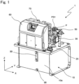
- Fig. 1 is a perspective view of a front side of a hydraulic unit 1 according to a first embodiment of the present disclosure as viewed obliquely from above
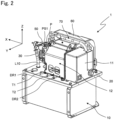
- Fig. 2 is a perspective view of a rear side of the hydraulic unit 1 as viewed obliquely from above.
- the hydraulic unit 1 is used in an industrial machine (main machine) such as an injection molding machine, a press machine, or a machine tool (the same applies to hydraulic units 2 to 6 according to second to sixth embodiments).
- the hydraulic unit 1 includes an oil tank 10 that stores a hydraulic oil (fluid), a base 20 attached to an upper portion of the oil tank 10, a hydraulic pump 30, a motor 40 (illustrated in Fig. 3 ) that drives the hydraulic pump 30, a relief valve 50 connected to a discharge port 30a (illustrated in Fig. 14 ) of the hydraulic pump 30, and a controller 60 that controls the motor 40 and the like.
- the hydraulic pump 30, the motor 40, the relief valve 50, and the controller 60 are mounted on the base 20.
- An oil level gauge 99 is attached to a side wall 10a on a front side of the oil tank 10.
- An oil-drain port 98 is provided below the oil level gauge 99 on the side wall 10a of the oil tank 10.
- the controller 60 is an example of a control unit.
- Fig. 2 11 denotes a first protection cover that covers a side of the motor 40 remote from the hydraulic pump 30, an electromagnetic valve V1 (illustrated in Fig. 3 ), and the like, 12 denotes a second protection cover that covers a main part of the motor 40, and 70 denotes a first heat exchanger that cools the hydraulic oil.
- L10 denotes a drain hose
- P denotes a pump port
- T1 and T2 denote tank ports
- DR1 and DR2 denote drain ports.
- the electromagnetic valve V1 is an example of a flow rate control valve.
- Fig. 3 is a perspective view of the hydraulic unit 1 with the first and second protection covers 11 and 12 removed
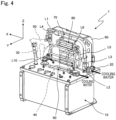
- Fig. 4 is a perspective view of the hydraulic unit 1 with the first and second protection covers 11 and 12, the motor 40, the hydraulic pump 30, and the like removed.
- 90 denotes a third heat exchanger that is in thermal contact with a housing 40a of the motor 40
- V1 denotes the electromagnetic valve.
- Fig. 5 is a perspective view of the hydraulic unit 1 with the first and second protection covers 11 and 12 removed, as viewed from the rear side and obliquely from above
- Fig. 6 is a perspective view of the hydraulic unit 1 with the first and second protection covers 11 and 12, the motor 40, the hydraulic pump 30, and the like removed.
- L7 denotes a drain pipe connected to an outlet of the electromagnetic valve V1.
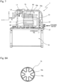
- Fig. 7 is a rear view of the hydraulic unit 1 with the first and second protection covers 11 and 12, the motor 40, the hydraulic pump 30, and the like removed.
- the third heat exchanger 90 is not illustrated in Fig. 7 .
- the first heat exchanger 70 cools the hydraulic oil by causing cooling water to exchange heat with the hydraulic oil returning to the oil tank 10 through pipes L1 and L2.
- the pipes L1 and L2 are examples of a first return pipe.
- the controller 60 includes a device (an element, a part, or a component) 61 of an inverter circuit (not illustrated) and a heat sink 62 thermally coupled to the device 61, the device 61 driving the motor 40.
- a pipe L5 into which the cooling water flows from a pipe L4 is in thermal contact with the heat sink 62.
- the pipe L5 and the heat sink 62 constitute a second heat exchanger 80.
- the controller 60 includes a central processing unit (CPU), a memory, and an input/output circuit.
- the device 61 is a power semiconductor such as an insulated gate bipolar transistor (IGBT).
- the cooling water from the second heat exchanger 80 flows into a pipe L6 that is in thermal contact with the housing 40a of the motor 40.
- the pipe L6 and the housing 40a of the motor 40 constitute the third heat exchanger 90.
- the hydraulic oil from the hydraulic pump 30 flows into a flow path between an outer peripheral surface of an inner pipe 70a and an inner peripheral surface of an outer pipe 70b through the pipe L1.
- the hydraulic oil returns from the flow path to the oil tank 10 through the pipe L2.
- the cooling water supplied from an external supply source flows into the inner pipe 70a of the first heat exchanger 70 through the pipe L3.
- the cooling water from the inner pipe 70a flows out through the pipe L4.
- the cooling water may flow between the outer peripheral surface of the inner pipe 70a and the inner peripheral surface of the outer pipe 70b of the first heat exchanger 70.
- the cooling water from the pipe L4 flows into the pipe L5 of the second heat exchanger 80 to cause the second heat exchanger 80 to cool the heat sink 62 of the controller 60. Accordingly, the device 61 thermally coupled to the heat sink 62 is cooled.
- the cooling water from the second heat exchanger 80 flows into the pipe L6 of the third heat exchanger 90 to cause the third heat exchanger 90 to cool the motor 40. Then, the cooling water from the third heat exchanger 90 is discharged to the outside through the electromagnetic valve V1 and the drain pipe L7.
- the cooling water given herein is an example of a coolant, and in this embodiment, industrial water is used.
- the coolant for example, cooling water supplied from a cooling water circulation device or the like may be used.
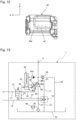
- the first heat exchanger 70 is a double pipe including an inner pipe 70a with a multi-lobed cross section and an outer pipe 70b with a circular cross section that accommodates the inner pipe 70a.
- the inner pipe 70a with a multi-lobed cross section is twisted so as to increase heat exchange efficiency.
- the first heat exchanger 70 has a longitudinal dimension of 300 mm, and the inner pipe 70a is twisted at intervals of 300 mm to 600 mm.
- a first heat exchanger 170 of double-pipe structure including an inner pipe 170a with a circular cross section and an outer pipe 170b with a circular cross section that accommodates the inner pipe 170a, and the first heat exchange unit may be a plate heat exchanger or the like.
- Fig. 9 is a perspective view of the hydraulic unit 1 as viewed from the rear side and obliquely below.
- 31 denotes a suction pipe 31 having an upper end connected to an inlet port of the hydraulic pump 30
- 32 denotes a suction strainer attached to a lower end of the suction pipe 31
- 33 denotes a partition wall.
- L41 denotes a pipe having an upper end connected to the tank port T1
- L42 denotes a pipe having an upper end connected to the tank port T2.
- Fig. 10 is a side view of the motor 40 of the hydraulic unit 1
- Fig. 11 is a top view of the motor 40 with the pipe L6 removed
- Fig. 12 is a bottom view of the motor with the pipe L6 removed.
- the pipe L6 meanders and is in thermal contact with the housing 40a of the motor 40.
- a U-shaped groove 41 in which the pipe L6 is partially fitted is provided in an upper portion of the housing 40a.
- a U-shaped groove 42 in which the pipe L6 is partially fitted is provided in the bottom portion of the housing 40a.
- the pipe L6 is fixed to the grooves 41 and 42 of the housing 40a using heat transfer cement.
- the pipe L6 is fitted in the grooves 41 and 42 of the housing 40a of the motor 40 to increase a contact area between the housing 40a of the motor 40 and the pipe L6, so as to increase the heat exchange efficiency.
- Fig. 13 is a circuit diagram of the hydraulic unit 1.
- the hydraulic unit 1 includes the hydraulic pump 30 of a fixed displacement type, the motor 40 of a variable speed type, the relief valve 50, a pressure sensor PS1, the controller 60, and the oil tank 10.
- the hydraulic pump 30 supplies the hydraulic oil to an actuator (for example, a hydraulic cylinder) belonging to the main machine.
- the motor 40 drives the hydraulic pump 30.
- the relief valve 50 is connected to the discharge port 30a of the hydraulic pump 30.
- the pressure sensor PS1 detects a discharge pressure of the hydraulic pump 30.
- the controller 60 controls the number of rotations of the motor 40.
- the oil tank 10 stores the hydraulic oil.
- the hydraulic unit 1 has the pump port P connected to the main machine through a pipe (not illustrated). Although not illustrated, the hydraulic unit 1 has a tank ports Tland T2 connected to the main machine through pipes.
- the hydraulic pump 30 sucks the hydraulic oil in the oil tank 10 through the suction strainer 32 and the suction pipe 31, and discharges the hydraulic oil from the discharge port 30a.
- the hydraulic oil is returned to the oil tank 10 through the relief valve 50 and the drain hose L10.
- the hydraulic oil is returned from a flow path between the discharge port 30a of the hydraulic pump 30 and the actuator to the oil tank 10 through a throttle 51 and the pipes L1 and L2.
- the pipes L1 and L2 are examples of the first return pipe.
- the hydraulic oil is returned to the oil tank 10 through the relief valve 50 and the drain hose L10, or alternatively, the outlet of the relief valve 50 may be connected to the inlet of the hydraulic pump 30 through a pipe.
- the controller 60 controls the number of rotations of the motor 40 and opens and closes the electromagnetic valve V1 on the basis of a pressure command signal or a flow rate command signal from the main machine, a pressure signal from the pressure sensor PS1, or the like.
- the hydraulic pump 30 of a fixed displacement type is used, or alternatively, a hydraulic pump of a variable displacement type may be used.
- the electromagnetic valve V1 is in a closed state.
- the cooling water supplied from the external supply source flows into the first heat exchanger 70, the second heat exchanger 80, and the third heat exchanger 90 in this order to cool the hydraulic oil, the device 61, and the motor 40. Then, the cooling water from the third heat exchanger 90 is discharged to the outside through the electromagnetic valve V1.
- the first heat exchanger 70 causes the coolant to exchange heat with the hydraulic oil returning to the oil tank 10 through the pipes L1 and L2. Therefore, it is possible to increase performance of cooling the hydraulic oil even under an environment where the ambient temperature is high.
- the first heat exchanger 70 of double-pipe structure includes the inner pipe 70a with a multi-lobed cross section and the outer pipe 70b accommodating the inner pipe 70a.
- the use of the first heat exchanger 70 allows an increase in the performance of cooling the hydraulic oil in the first heat exchanger 70 that can be downsized.
- the second heat exchanger 80 causesthe coolant to exchange heat with the device 61 that drives the motor 40, so that it is possible to increase performance of cooling the device 61 as compared with air cooling.
- the third heat exchanger 90 causes the coolant to exchange heat with the motor 40 that drives the hydraulic pump 30, so that it is possible to increase performance of cooling the motor 40 as compared with air cooling.
- the first heat exchanger 70 can cool the hydraulic oil, and the second and third heat exchangers 80 and 90 can cool the device 61 and the motor 40. It is further possible to simplify, by connecting the first heat exchanger 70, the second heat exchanger 80, and the third heat exchanger 90 in series, a piping configuration for the coolant. It is further possible to cause the electromagnetic valve V1 (flow rate control valve) to simultaneously regulate the flow rate of the coolant supplied to the first heat exchanger 70, the second heat exchanger 80, and the third heat exchanger 90. The first heat exchanger 70, the second heat exchanger 80, and the third heat exchanger 90 are connected in series in the order of the first heat exchanger 70, the second heat exchanger 80, and the third heat exchanger 90.
- V1 flow rate control valve
- the first heat exchanger 70 first cools the hydraulic oil to increase the temperature of the coolant so that the second and third heat exchangers 80 and 90 have temperatures at which the device 61 and the motor 40 are prevented from suffering from water condensation.
- Closing the electromagnetic valve V1 (flow rate control valve) prevents the cooling water from flowing to the second and third heat exchangers 80 and 90, so that it is possible to prevent the device 61 and the motor 40 from suffering from water condensation due to excessive cooling.
- the hydraulic unit 1 includes a first temperature sensor (not illustrated) that detects the temperature of the hydraulic oil in the oil tank 10, a second temperature sensor (not illustrated) that detects the temperature of the device 61, and a third temperature sensor (not illustrated) that detects the temperature of the motor 40.
- the controller 60 can optimize the flow rate of the coolant flowing through the first heat exchanger 70, the second heat exchanger 80, and the third heat exchanger 90 by controlling to open and close the electromagnetic valve V1 in accordance with the temperature of the hydraulic oil detected by the first temperature sensor, the temperature of the device 61 detected by the second temperature sensor, and the temperature of the motor 40 detected by the third temperature sensor.
- the electromagnetic valve V1 is controlled on the basis of pulse width modulation (PWM) control.
- the third temperature sensor may detect the temperature of the housing 40a of the motor 40, the temperature of a coil, or the like.
- the above-described hydraulic unit 1 can realize liquid cooling of the hydraulic oil, the device 61 of the controller 60, and the motor 40 while suppressing the occurrence of water condensation with a size equivalent to the size of a known air-cooled hydraulic unit.
- the flow rate of the coolant supplied to the first heat exchanger 70, the second heat exchanger 80, and the third heat exchanger 90 is regulated by the electromagnetic valve V1, or alternatively, a flow rate control valve capable of controlling the opening degree continuously or in multiple levels may be used instead of the electromagnetic valve V1.
- the opening degree of the flow rate control valve is controlled in accordance with the temperature of the hydraulic oil, the temperature of the device 61, and the temperature of the motor 40.
- the outlet of the relief valve 50 may be connected to one end of a pipe L8, and the pipe L1 may be connected to the other end of the pipe L8. This causes the hydraulic oil from the relief valve 50 and the hydraulic oil from the throttle 51 to merge with and be cooled by the first heat exchanger 70.
- the pipe L8 is an example of the first return pipe.
- the first heat exchanger 70 when the hydraulic oil is returned from the flow path between the discharge port 30a of the hydraulic pump 30 and the actuator to the oil tank 10 through the relief valve 50, the first heat exchanger 70 causes the coolant to exchange heat with the hydraulic oil returning to the oil tank 10 through the pipe L8, so that it is possible to further increase the performance of cooling the hydraulic oil. Since the first heat exchanger 70 of double-pipe configuration has no joint and thus has high strength as compared with an oil cooler of the known air-cooled hydraulic unit, the first heat exchanger 70 can cool the hydraulic oil flowing through the pipe L8.
- the pipe L8 is a flow path in which surge pressure is generated.
- the second heat exchanger 80 and the third heat exchanger 90 may be connected in parallel, and the first heat exchanger 70 may be connected in series to the second heat exchanger 80 and the third heat exchanger 90 connected in parallel.
- Fig. 16 is a circuit diagram of a hydraulic unit 2 according to a second embodiment of the present disclosure.
- the hydraulic unit 2 according to the second embodiment is identical in configuration to the hydraulic unit 1 illustrated in Fig. 14 as a modification of the first embodiment except for the connection configuration of the first heat exchanger 70, the second heat exchanger 80, and the third heat exchanger 90, and electromagnetic valves V11, V12, and V13.
- the hydraulic unit 2 includes the electromagnetic valve V11 (first flow rate control valve) that controls the flow rate of the coolant supplied to the first heat exchanger 70, the electromagnetic valve V12 (second flow rate control valve) that controls the flow rate of the coolant supplied to the second heat exchanger 80, and the electromagnetic valve V13 (third flow rate control valve) that controls the flow rate of the coolant supplied to the third heat exchanger 90.
- the cooling water supplied from the external supply source flows into the first heat exchanger 70 through the electromagnetic valve V11 and a pipe L13, and flows out from the first heat exchanger 70 through a pipe L14.
- the cooling water supplied from the external supply source flows into the second heat exchanger 80 through a pipe L17, and flows out from the second heat exchanger 80 through a pipe L18 and the electromagnetic valve V12.
- the cooling water supplied from the external supply source flows into the third heat exchanger 90 through a pipe L15, and flows out from the third heat exchanger 90 through a pipe L16 and the electromagnetic valve V13.
- the hydraulic unit 2 according to the second embodiment has the same effect as the hydraulic unit 1 of the first embodiment has.
- the electromagnetic valve V11 can regulate the flow rate of the coolant supplied to the first heat exchanger 70
- the electromagnetic valve V12 can regulate the flow rate of the coolant supplied to the second heat exchanger 80
- the electromagnetic valve V13 can regulate the flow rate of the coolant supplied to the third heat exchanger 90.
- the hydraulic unit 2 includes a first temperature sensor (not illustrated) that detects the temperature of the hydraulic oil in the oil tank 10, a second temperature sensor (not illustrated) that detects the temperature of the device 61, and a third temperature sensor (not illustrated) that detects the temperature of the motor 40.
- the controller 60 can optimize the flow rate of the coolant flowing through the first heat exchanger 70, the second heat exchanger 80, and the third heat exchanger 90 by controlling to open and close the electromagnetic valve V11, V12, and V13 in accordance with the temperature of the hydraulic oil detected by the first temperature sensor, the temperature of the device 61 detected by the second temperature sensor, and the temperature of the motor 40 detected by the third temperature sensor.
- the controller 60 can keep the hydraulic oil at an appropriate temperature by controlling the electromagnetic valve V11 (first flow rate control valve) to regulate the flow rate of the coolant flowing through the first heat exchanger 70, so as to make a temperature To of the hydraulic oil higher than or equal to a predetermined first hydraulic oil temperature To1 and lower than or equal to a predetermined second hydraulic oil temperature To2 (> To1).
- V11 first flow rate control valve
- the controller 60 can keep the device 61 at an appropriate temperature by controlling the electromagnetic valve V12 (second flow rate control valve) to regulate the flow rate of the coolant flowing through the second heat exchanger 80, so as to make a temperature Td of the device 61 higher than or equal to a predetermined first device temperature Td1 and lower than or equal to a predetermined second device temperature Td2 (> Td1).
- the controller 60 can keep the motor 40 at an appropriate temperature by controlling the electromagnetic valve V13 (third flow rate control valve) to regulate the flow rate of the coolant flowing through the third heat exchanger 90, so as to make a temperature Tm of the motor 40 higher than or equal to a predetermined first motor temperature Tm1 and lower than or equal to a predetermined second motor temperature Tm2 (> Tm1).Setting the device 61 at the predetermined second device temperature Td2 makes it possible to suppress heat-induced deterioration. Setting the motor 40 at the predetermined second motor temperature Tm2 makes it possible to suppress heat-induced deterioration.
- the first device temperature Td1 is a temperature at which the device 61 is prevented from suffering from water condensation
- the first motor temperature Tm1 is a temperature at which the motor 40 is prevented from suffering from water condensation.
- the above-described hydraulic unit 2 according to the second embodiment has the same effect as the hydraulic unit 1 of the first embodiment has.
- Fig. 17 is a circuit diagram of a hydraulic unit 3 according to a third embodiment of the present disclosure.
- 55 denotes a filter.
- the hydraulic unit 3 includes a pair of hydraulic pumps 30A and 30B that supply the hydraulic oil to the actuator (for example, a hydraulic cylinder) belonging to the main machine, the motor 40 of a variable speed type that drives the hydraulic pump 30A and 30B, a relief valve 50A connected to a discharge port 30Aa of the hydraulic pump 30A, a relief valve 50B connected to a discharge port 30Ba of the hydraulic pump 30B, the pressure sensor PS1 that detects a discharge pressure of the hydraulic pumps 30A and 30B, the controller 60 that controls the number of rotations of the motor 40, and the oil tank 10 that stores the hydraulic oil.
- the hydraulic pump 30A is a large-capacity fixed displacement pump
- the hydraulic pump 30B is a small-capacity fixed displacement pump.
- the hydraulic unit 3 includes a flow path switching valve V2 that switches whether the discharge port 30Aa of the hydraulic pump 30A is connected to a pipe close the discharge port 30Ba of the hydraulic pump 30B or the discharge port 30Aa of the hydraulic pump 30A is connected to a pipe L1B.
- a check valve 53 that regulates the flow of the hydraulic oil toward the hydraulic pump 30B is provided between the discharge port 30Ba of the hydraulic pump 30B and the pump port P.
- a throttle 54 is connected in parallel to the check valve 53.
- the flow path switching valve V2 switches whether to cause the hydraulic pump 30B to solely control the pressure and flow rate at the pump port P or to cause both the hydraulic pump 30A and the hydraulic pump 30B to control the pressure and flow rate at the pump port P.
- the pump port P of the hydraulic unit 3 is connected to the main machine through a pipe (not illustrated).
- the tank ports T1 and T2 of the hydraulic unit 3 is connected to the main machine through pipes (not illustrated).
- the hydraulic pump 30A sucks the hydraulic oil in the oil tank 10 through the suction strainer 32 and the suction pipe 31, and discharges the hydraulic oil from the discharge port 30Aa.
- the hydraulic pump 30B sucks the hydraulic oil in the oil tank 10 through the suction strainer 32 and the suction pipe 31, and discharges the hydraulic oil from the discharge port 30Ba.
- the suction pipe 31 branches off at its upper side to connect to the respective inlet ports of the hydraulic pumps 30A and 30B.
- the hydraulic oil is returned from a flow path between the discharge port 30Aa of the hydraulic pump 30A and the actuator to the oil tank 10 through the relief valve 50A, the pipe L1B, a heat exchanger 70B, and a pipe L2B.
- the hydraulic oil is returned from a flow path between the discharge port 30Ba of the hydraulic pump 30B and the actuator to the oil tank 10 through the relief valve 50B, the pipe L1B, the heat exchanger 70B, and the pipe L2B.
- the hydraulic oil is returned from a flow path between the discharge port 30Ba of the hydraulic pump 30B and the actuator to the oil tank 10 through a throttle 52, a pipe L1A, a heat exchanger 70A, and a pipe L2A.
- the pipes L1A, L1B, L2A, and L2B are examples of the first return pipe.
- the heat exchangers 70A and 70B are examples of the first heat exchanger.
- the cooling water supplied from the external supply source flows into the heat exchanger 70A through an electromagnetic valve V21A and a pipe L11A, and flows out from the heat exchanger 70A through a pipe L12A.
- the cooling water supplied from the external supply source flows into the heat exchanger 70B through an electromagnetic valve V21B and a pipe L11B, and flows out from the heat exchanger 70B through a pipe L12B.
- the cooling water supplied from the external supply source flows into the second heat exchanger 80 through an electromagnetic valve V22 and a pipe L21, and flows out from the second heat exchanger 80 through a pipe L22.
- the cooling water supplied from the external supply source flows into the third heat exchanger 90 through an electromagnetic valve V23 and a pipe L31, and flows out from the third heat exchanger 90 through a pipe L32.
- the controller 60 controls the number of rotations of the motor 40 and opens and closes the electromagnetic valve V21A, V21B, V22, or V23 on the basis of the pressure command signal or the flow rate command signal from the main machine, the pressure signal from the pressure sensor PS 1, or the like.
- the hydraulic pumps 30A and 30B of a fixed displacement type is used, or alternatively, a hydraulic pump of a variable displacement type may be used.
- the heat exchangers 70A and 70B cause the coolant to exchange heat with the hydraulic oil returning to the oil tank 10 through the pipes L1A, L1B, L2A, and L2B.
- the heat exchangers 70A and 70B cause the coolant to exchange heat with the hydraulic oil returning to the oil tank 10 through the pipes L1A, L1B, L2A, and L2B.
- the heat exchangers 70A and 70B can cool the hydraulic oil flowing through the pipe L1B, which is a flow path in which surge pressure is generated.
- the second heat exchanger 80 causes the coolant to exchange heat with the device 61 that drives the motor 40, so that it is possible to increase the performance of cooling the device 61 as compared with air cooling.
- the third heat exchanger 90 causes the coolant to exchange heat with the motor 40 that drives the hydraulic pumps 30A and 30B, so that it is possible to increase the performance of cooling the motor 40 as compared with air cooling.
- the hydraulic unit 3 can cause the electromagnetic valve V21A (first flow rate control valve) to regulate the flow rate of the coolant supplied to the heat exchanger 70A, cause the electromagnetic valve V21B (first flow rate control valve) to regulate the flow rate of the coolant supplied to the heat exchanger 70B, cause the electromagnetic valve V22 (second flow rate control valve) to regulate the flow rate of the coolant supplied to the second heat exchanger 80, and cause the electromagnetic valve V23 (third flow rate control valve) to regulate the flow rate of the coolant supplied to the third heat exchanger 90.
- first flow rate control valve first flow rate control valve
- the hydraulic unit 3 includes a first temperature sensor (not illustrated) that detects the temperature of the hydraulic oil in the oil tank 10, a second temperature sensor (not illustrated) that detects the temperature of the device 61, and a third temperature sensor (not illustrated) that detects the temperature of the motor 40.
- the controller 60 can optimize the flow rate of the coolant flowing through the first heat exchanger 70, the second heat exchanger 80, and the third heat exchanger 90 by controlling to open and close the electromagnetic valves V21A, V21B, V22, and V23 in accordance with the temperature of the hydraulic oil detected by the first temperature sensor, the temperature of the device 61 detected by the second temperature sensor, and the temperature of the motor 40 detected by the third temperature sensor.
- the controller 60 can keep the hydraulic oil at an appropriate temperature by controlling the electromagnetic valves V21A and V21B (first flow rate control valve) to regulate the flow rate of the coolant flowing through the first heat exchangers 70A and 70B, so as to make the temperature To of the hydraulic oil higher than or equal to the predetermined first hydraulic oil temperature To1 and lower than or equal to the predetermined second hydraulic oil temperature To2 (> To1).
- the controller 60 can keep the device 61 at an appropriate temperature by controlling the electromagnetic valve V22 to regulate the flow rate of the coolant flowing through the second heat exchanger 80, so as to make the temperature Td of the device 61 higher than or equal to the predetermined first device temperature Td1 and lower than or equal to the predetermined second device temperature Td2 (> Td1).
- the controller 60 can keep the motor 40 at an appropriate temperature by controlling the electromagnetic valve V22 to regulate the flow rate of the coolant flowing through the third heat exchanger 90, so as to make the temperature Tm of the motor 40 higher than or equal to the predetermined first motor temperature Tm1 and lower than or equal to the predetermined second motor temperature Tm2 (> Tm1).
- the first device temperature Td1 is a temperature at which the device 61 is prevented from suffering from water condensation
- the first motor temperature Tm1 is a temperature at which the motor 40 is prevented from suffering from water condensation.
- the flow rate of the coolant supplied to each of the heat exchangers 70A and 70B, the second heat exchanger 80, and the third heat exchanger 90 is regulated by controlling to open and close the electromagnetic valves V21A, V21B, V22, and V23, or alternatively, a flow rate control valve capable of controlling the opening degree continuously or in a multiple levels may be used instead of the electromagnetic valves V21A, V21B, V22, and V23.
- the two heat exchangers 70A and 70B are used as the first heat exchanger, or alternatively, as illustrated in Fig. 18 , the hydraulic oil may be cooled by a single first heat exchanger 70 instead of the heat exchangers 70A and 70B.
- the hydraulic oil is returned from a flow path between the discharge port 30Aa of the hydraulic pump 30A and the actuator to the oil tank 10 through the relief valve 50A, the pipe L1B, the first heat exchanger 70, and the pipe L2.
- the hydraulic oil is returned from a flow path between the discharge port 30Ba of the hydraulic pump 30B and the actuator to the oil tank 10 through the relief valve 50B, the pipe L1B, the first heat exchanger 70, and the pipe L2B.
- the hydraulic oil is returned from a flow path between the discharge port 30Ba of the hydraulic pump 30B and the actuator to the oil tank 10 through the throttle 52, the pipe L1A, the first heat exchanger 70, and the pipe L2.
- the pipes L1A, L1B, and L2 are examples of the first return pipe.
- Fig. 19 is a circuit diagram of a hydraulic unit 4 according to a fourth embodiment of the present disclosure.
- the hydraulic unit 4 according to the fourth embodiment is identical in configuration to the hydraulic unit 1 according to the first embodiment except that the second and third heat exchangers 80 and 90 are not provided and that a fan F is further provided.
- L41 denotes a pipe that guides the hydraulic oil from the tank port T1 to the oil tank 10
- L42 denotes a pipe that guides the hydraulic oil from the tank port T2 to the oil tank
- L43 denotes a pipe that guides the hydraulic oil from the drain port DR1 to the oil tank 10
- L44 denotes a pipe that guides the hydraulic oil from the drain port DR2 to the oil tank 10.
- the hydraulic unit 4 includes the fan F that supplies cooling air to both the motor 40 and the heat sink 62 of the controller 60 (control unit).
- the heat sink 62 is cooled by the air supplied from the fan F so as to cool the device 61 thermally coupled to the heat sink 62.
- the hydraulic unit 4 includes a first temperature sensor (not illustrated) that detects the temperature of the hydraulic oil in the oil tank 10.
- the controller 60 can optimize the flow rate of the coolant flowing through the first heat exchanger 70 by controlling to open and close the electromagnetic valve V1 in accordance with the temperature of the hydraulic oil detected by the first temperature sensor.
- the controller 60 can keep the hydraulic oil at an appropriate temperature by controlling the electromagnetic valve V1 to regulate the flow rate of the coolant flowing through the first heat exchanger 70, so as to make the temperature To of the hydraulic oil higher than or equal to the predetermined first hydraulic oil temperature To1 and lower than or equal to the predetermined second hydraulic oil temperature To2 (> To1).
- both the motor 40 and the device 61 of the controller 60 are cooled by the air supplied from the fan F, so that it is possible to make the configuration simple as compared with a case where a heat exchanger for cooling is provided in the motor 40 or the device 61 of the controller 60.
- either one of the motor 40 and the device 61 of the controller 60 (control unit) may be cooled by the air supplied from the fan F, and the other of the motor 40 and the device 61 of the controller 60 (control unit) may be cooled by liquid in a manner similar to the first to third embodiments.
- the hydraulic oil is returned to the oil tank 10 through the relief valve 50 and the drain hose L10, or alternatively, as illustrated in Fig. 20 , the hydraulic oil from the relief valve 50 and the tank ports T1 and T2 may be guided to the first heat exchanger 70 for cooling.
- the pipe L8 has one end connected to the outlet of the relief valve 50 and has the other end connected to the pipe L1, the tank port T1 is connected to the pipe L8 through the pipe L41, and the tank port T2 is connected to the pipe L41 through the pipe L42.
- the pipe L8 is an example of the first return pipe, and the pipes L41 and L42 are examples of a second return pipe.
- the first heat exchanger 70 causes the coolant to exchange heat with the hydraulic oil returning to the oil tank 10 through the pipes L41 and L42. This causes the first heat exchanger 70 to cool not only the hydraulic oil returning from a flow path between the discharge port 30a of the hydraulic pump 30 and the actuator to the oil tank 10 through the relief valve 50 but also the hydraulic oil discharged from the actuator, so that it is possible to further increase the performance of cooling the hydraulic oil.
- the hydraulic oil is guided from the drain port DR1 to the oil tank 10 through the pipe L43, and the hydraulic oil is guided from the drain port DR2 to the oil tank 10 through the pipe L44, or alternatively, as illustrated in Fig. 21 , the hydraulic oil from the drain ports DR1 and DR2 may be guided to the first heat exchanger 70 for cooling.
- the drain port DR1 is connected to the pipe L1 through the pipe L43
- the drain port DR2 is connected to the pipe L43 through the pipe L44.
- the pipes L1 and L2 are examples of the first return pipe, and the pipes L43 and L 44 are examples of the second return pipe.
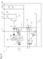
- Fig. 22 is a circuit diagram of a hydraulic unit 5 according to a fifth embodiment of the present disclosure.
- the hydraulic unit 5 according to the fifth embodiment is identical in configuration to a modification of the hydraulic unit 4, illustrated in Fig. 21 , according to the fourth embodiment except that the fan F is not provided and that second and third heat exchangers 180, 190 using the hydraulic oil cooled by the first heat exchanger 70 as a coolant are further provided.
- the hydraulic unit 5 causes the second heat exchanger 180 to cool the device 61 of the controller 60 with the hydraulic oil cooled by the first heat exchanger 70.
- the second heat exchanger 180 cools the motor 40 with the hydraulic oil from the second heat exchanger 180.
- the hydraulic oil from the third heat exchanger 190 returns to the oil tank 10 through a pipe L2c.
- the hydraulic oil flows from the second heat exchanger 180 to the third heat exchanger 190 in this order, or alternatively, the hydraulic oil may flow from the third heat exchanger 190 to the second heat exchanger 180 in this order.
- the hydraulic unit 5 includes a temperature sensor (not illustrated) that detects the temperature of the hydraulic oil in the oil tank 10.
- the controller 60 can optimize the flow rate of the coolant flowing through the first heat exchanger 70 by controlling to open and close the electromagnetic valve V1 in accordance with the temperature of the hydraulic oil detected by the temperature sensor.
- the controller 60 can keep the hydraulic oil at an appropriate temperature by controlling the electromagnetic valve V1 to regulate the flow rate of the coolant flowing through the first heat exchanger 70, so as to make the temperature To of the hydraulic oil higher than or equal to the predetermined first hydraulic oil temperature To1 and lower than or equal to the predetermined second hydraulic oil temperature To2 (> To1).
- the hydraulic oil cooled by the first heat exchanger 70 be kept at about 40°C, which makes it possible to cool the motor 40 and the device 61 of the controller 60 to the extent that the motor 40 and the device 61 are prevented from suffering from water condensation due to excessive cooling.
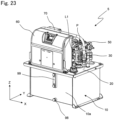
- Fig. 23 is a perspective view of a front side of the hydraulic unit 5 as viewed obliquely from above
- Fig. 24 is a perspective view of a rear side of the hydraulic unit 5 as viewed obliquely from above
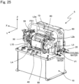
- Fig. 25 is a perspective view of the hydraulic unit 5 with the first and second protection covers 11 and 12 removed
- Fig. 26 is a perspective view of the hydraulic unit 5 with the first and second protection covers 11 and 12, the motor 40, the hydraulic pump 30, and the like removed.
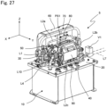
- Fig. 27 is a perspective view of the hydraulic unit 5 with the first and second protection covers 11 and 12 removed, as viewed from the rear side and obliquely from above
- Fig. 28 is a perspective view of the hydraulic unit 5 with the first and second protection covers 11 and 12, the motor 40, the hydraulic pump 30, and the like removed.
- Fig. 29 is a rear view of the hydraulic unit 5 with the first and second protection covers 11 and 12, the motor 40, the hydraulic pump 30, and the like removed.
- the first heat exchanger 70 cools the hydraulic oil by causing the hydraulic oil returning to the oil tank 10 through the pipes L1, L2a, L2b, and L2c and the cooling water to exchange heat with each other.
- the pipes L1, L2a, L2b, and L2c are examples of the first return pipe.
- the controller 60 includes the device 61 of an inverter circuit (not illustrated) that drives the motor 40 and the heat sink 62 thermally coupled to the device 61.
- the pipe L2a into which the cooled hydraulic oil from the first heat exchanger 70 flows is in thermal contact with the heat sink 62.
- the pipe L2a and the heat sink 62 constitute the second heat exchanger 180.
- the hydraulic oil from the second heat exchanger 180 flows into the pipe L2b that is in thermal contact with the housing 40a of the motor 40.
- the pipe L2b and the housing 40a of the motor 40 constitute the third heat exchanger 190.
- the hydraulic oil from the hydraulic pump 30 flows into a flow path between the outer peripheral surface of the inner pipe 70a (illustrated in Fig. 8A ) of the first heat exchanger 70 and the inner peripheral surface of the outer pipe 70b (illustrated in Fig. 8A ) of the first heat exchanger 70 through the pipe L1, and the hydraulic oil from the flow path returns to the oil tank 10 through the second and third heat exchangers 180 and 190.
- the cooling water supplied from the external supply source flows into the inner pipe 70a of the first heat exchanger 70 through the pipe L3, and the cooling water from the inner pipe 70a flows out through the pipe L4.
- the cooling water may flow between the outer peripheral surface of the inner pipe 70a of the first heat exchanger 70 and the inner peripheral surface of the outer pipe 70b of the first heat exchanger 70.
- the cooling water from the first heat exchanger 70 is discharged to the outside through the electromagnetic valve V1 and the drain pipe L7.
- the hydraulic unit 5 according to the fifth embodiment has the same effect as the hydraulic unit 1 of the first embodiment has.
- the second heat exchanger 180 can cool the device 61 of the controller 60 with the hydraulic oil flowing through the first return pipes (L2a, L2b, and L2c) downstream of the first heat exchanger 70 so as to prevent device 61 from suffering from water condensation due to excessive cooling.
- the third heat exchanger 190 can cool the motor 40 with the hydraulic oil flowing through the first return pipes (L2a, L2b, and L2c) downstream of the first heat exchanger 70 so as to prevent the motor 40 from suffering from water condensation due to excessive cooling.
- the hydraulic oil from the drain ports DR1 and DR2 is guided to the first heat exchanger 70 for cooling, or alternatively, the hydraulic oil from the drain ports DR1 and DR2 may be directly returned to the oil tank 10 through the pipes L43 and L44.
- Fig. 30 is a circuit diagram of a hydraulic unit 6 according to a sixth embodiment of the present disclosure.
- the hydraulic unit 6 according to the sixth embodiment is identical in configuration to the hydraulic unit 5 according to the fifth embodiment except for the connection structure of drain ports DR2, DR3, and DR4 and that a fourth heat exchanger 200 is further provided.
- the hydraulic unit 6 causes the second heat exchanger 180 to cool the device 61 of the controller 60 and causes the third heat exchanger 190 to cool the motor 40 with the hydraulic oil cooled by the first heat exchanger 70.
- the fourth heat exchanger 200 cools the hydraulic oil flowing into the drain ports DR3 and DR4.
- the fourth heat exchanger 200 is identical in configuration to the first heat exchanger 70.
- the hydraulic oil discharged from the actuator for example, a hydraulic cylinder
- the like belonging to the main machine flows into the drain ports DR3 and DR4.
- the drain port DR3 is connected to one end of a pipe L45
- the hydraulic oil inlet of the fourth heat exchanger 200 is connected to the other end of the pipe L45
- the drain port DR4 is connected to one end of a pipe L46
- the pipe L45 is connected to the other end of the pipe L46.
- the hydraulic oil outlet of the fourth heat exchanger 200 is connected to one end of a pipe L47
- the pipe L1 is connected to the other end of the pipe L47.
- the pipe L45 and the drain port DR2 are connected through a check valve 56.
- the check valve 56 restricts the flow of the hydraulic oil from the drain port DR2 toward the pipe L45, and opens when the pressure applied to the pipe L45 becomes higher than or equal to a predetermined pressure to allow the hydraulic oil to flow from the pipe L45 toward the drain port DR2.
- the hydraulic unit 6 includes a temperature sensor (not illustrated) that detects the temperature of the hydraulic oil in the oil tank 10.
- the controller 60 can optimize the flow rate of the coolant flowing through the first heat exchanger 70 by controlling to open and close the electromagnetic valve V1 in accordance with the temperature of the hydraulic oil detected by the temperature sensor.
- the controller 60 can keep the hydraulic oil at an appropriate temperature by controlling the electromagnetic valve V1 to regulate the flow rate of the coolant flowing through the first heat exchanger 70, so as to make the temperature To of the hydraulic oil higher than or equal to the predetermined first hydraulic oil temperature To1 and lower than or equal to the predetermined second hydraulic oil temperature To2 (> To1).
- the hydraulic oil cooled by the first heat exchanger 70 be kept at about 40°C, which makes it possible to cool the motor 40 and the device 61 of the controller 60 to the extent that the motor 40 and the device 61 are prevented from suffering from water condensation due to excessive cooling.
- Fig. 31 is a perspective view of a front side of the hydraulic unit 6 as viewed obliquely from above
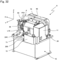
- Fig. 32 is a perspective view of a rear side of the hydraulic unit 6 as viewed obliquely from above
- Fig. 33 is a perspective view of the hydraulic unit 6 with the first and second protection covers 11 and 12 removed
- Fig. 34 is a perspective view of the hydraulic unit 6 with the first and second protection covers 11 and 12, the motor 40, the hydraulic pump 30, and the like removed.
- Fig. 35 is a perspective view of the hydraulic unit 6 with the first and second protection covers 11 and 12 removed, as viewed from the rear side and obliquely from above
- Fig. 36 is a perspective view of the hydraulic unit 6 with the first and second protection covers 11 and 12, the motor 40, the hydraulic pump 30, and the like removed.
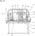
- Fig. 37 is a rear view of the hydraulic unit 6 with the first and second protection covers 11 and 12, the motor 40, the hydraulic pump 30, and the like removed.
- the first heat exchanger 70 cools the hydraulic oil by causing the hydraulic oil returning to the oil tank 10 through the pipes L1, L2a, L2b, and L2c and the cooling water to exchange heat with each other.
- the pipes L1, L2a, L2b, and L2c are examples of the first return pipe.
- the controller 60 includes the device 61 of an inverter circuit (not illustrated) that drives the motor 40 and the heat sink 62 thermally coupled to the device 61.
- the pipe L2a into which the cooled hydraulic oil from the first heat exchanger 70 flows is in thermal contact with the heat sink 62.
- the pipe L2a and the heat sink 62 constitute the second heat exchanger 180.
- the hydraulic oil from the second heat exchanger 180 flows into the pipe L2b that is in thermal contact with the housing 40a of the motor 40.
- the pipe L2b and the housing 40a of the motor 40 constitute the third heat exchanger 190.
- the fourth heat exchanger 200 cools the hydraulic oil by causing the hydraulic oil returning to the oil tank 10 through the pipes L45, L46, and L47 and the cooling water to exchange heat with each other.
- the pipes L45, L46, and L47 are examples of the second return pipe.
- the hydraulic oil from the hydraulic pump 30 flows into a flow path between the outer peripheral surface of the inner pipe 70a (illustrated in Fig. 8A ) and the inner peripheral surface of the outer pipe 70b (illustrated in Fig. 8A ) of the first heat exchanger 70 through the pipe L1, and the hydraulic oil from the flow path returns to the oil tank 10 through the second and third heat exchangers 180 and 190.
- the hydraulic oil from the drain ports DR3 and DR4 returns to the oil tank 10 through the fourth heat exchanger 200 and the first heat exchanger 70.
- the cooling water supplied from the external supply source flows into the inner pipe 70a of the first heat exchanger 70 through the pipe L3, and the cooling water from the inner pipe 70a flows into the fourth heat exchanger 200 through the pipe L4. Then, the cooling water from the fourth heat exchanger 200 is discharged to the outside through the pipe L5, the electromagnetic valve V1, and the drain pipe L7.
- the above-described hydraulic unit 6 according to the sixth embodiment has the same effect as the hydraulic unit 5 of the fifth embodiment has.
- the hydraulic oil from the drain ports DR3 and DR4 is returned to the oil tank 10 through the fourth heat exchanger 200 and the first heat exchanger 70, or alternatively, the hydraulic oil from the drain ports DR3 and DR4 may be directly returned to the oil tank 10 through the fourth heat exchanger 200. This case also allows an increase in the performance of cooling the hydraulic oil.
- the hydraulic oil cooled by the first heat exchanger 70 is returned to the oil tank 10 through the second and third heat exchangers 180 and 190, or alternatively, the hydraulic oil cooled by the first heat exchanger 70 may be directly returned to the oil tank 10 without passing through the second and third heat exchangers 180 and 190, and cooling air may be supplied from the fan to both the motor 40 and the heat sink 62 of the controller 60 (control unit) as in the fourth embodiment.
- Fig. 38 is a circuit diagram of a hydraulic unit 7 according to a seventh embodiment of the present disclosure.
- the hydraulic unit 7 according to the seventh embodiment is identical in configuration to the hydraulic unit 6 according to the sixth embodiment except for the connection structure of the drain ports DR2, DR3, and DR4 and the connection structure of the fourth heat exchanger 200.
- the hydraulic unit 7 causes the second heat exchanger 180 to cool the device 61 of the controller 60 and causes the third heat exchanger 190 to cool the motor 40 with the hydraulic oil cooled by the first heat exchanger 70.
- the fourth heat exchanger 200 cools the hydraulic oil flowing into the drain port DR4.
- the fourth heat exchanger 200 is identical in configuration to the first heat exchanger 70.
- the drain port DR3 is connected to the pipe L1 through the pipe L45.
- the hydraulic oil from the drain port DR3 is guided to the first heat exchanger 70 for cooling.
- the hydraulic oil discharged from the actuator for example, a hydraulic cylinder
- the like belonging to the main machine flows into the drain ports DR3 and DR4.
- the pipe L46 has one end connected to the drain port DR4 and has the other end connected to the hydraulic oil inlet of the fourth heat exchanger 200.
- the hydraulic oil is guided from the hydraulic oil outlet of the fourth heat exchanger 200 into the oil tank 10 through the pipe L47.
- the hydraulic unit 7 includes a temperature sensor (not illustrated) that detects the temperature of the hydraulic oil in the oil tank 10.
- the controller 60 can optimize the flow rate of the coolant flowing through the first heat exchanger 70 by controlling to open and close the electromagnetic valve V1 in accordance with the temperature of the hydraulic oil detected by the temperature sensor.
- the controller 60 can keep the hydraulic oil at an appropriate temperature by controlling the electromagnetic valve V1 to regulate the flow rate of the coolant flowing through the first heat exchanger 70, so as to make the temperature To of the hydraulic oil higher than or equal to the predetermined first hydraulic oil temperature To1 and lower than or equal to the predetermined second hydraulic oil temperature To2 (> To1).
- the hydraulic oil cooled by the first heat exchanger 70 be kept at about 40°C, which makes it possible to cool the motor 40 and the device 61 of the controller 60 to the extent that the motor 40 and the device 61 are prevented from suffering from water condensation due to excessive cooling.
- the hydraulic oil from the hydraulic pump 30 flows into a flow path between the outer peripheral surface of the inner pipe 70a (illustrated in Fig. 8A ) and the inner peripheral surface of the outer pipe 70b (illustrated in Fig. 8A ) of the first heat exchanger 70 through the pipe L1, and the hydraulic oil from the flow path returns to the oil tank 10 through the second and third heat exchangers 180 and 190.
- the hydraulic oil from the drain port DR4 returns to the oil tank 10 through the fourth heat exchanger 200.
- the hydraulic unit 7 according to the seventh embodiment can make the flow rate of the hydraulic oil in the first heat exchanger 70 lower to reduce pressure loss as compared with the sixth embodiment.
- the cooling water supplied from the external supply source flows into the inner pipe 70a of the first heat exchanger 70 through the pipe L3, and the cooling water from the inner pipe 70a flows into the fourth heat exchanger 200 through the pipe L4. Then, the cooling water from the fourth heat exchanger 200 is discharged to the outside through the pipe L5, the electromagnetic valve V1, and the drain pipe L7.
- the above-described hydraulic unit 7 according to the seventh embodiment has the same effect as the hydraulic unit 6 of the sixth embodiment has.
- a hydraulic unit includes:
- the first heat exchanger causes the hydraulic oil returning to the oil tank through the first return pipe and the coolant to exchange heat with each other, so that it is possible to increase performance of cooling the hydraulic oil even under an environment where an ambient temperature is high.
- a hydraulic unit according to a second aspect of the present disclosure is based on the hydraulic unit according to the first aspect and further includes a relief valve connected to the discharge port of the hydraulic pump, in which the first return pipe includes a pipe through which the hydraulic oil is returned to the oil tank through the relief valve.
- the first heat exchanger causes the hydraulic oil returning to the oil tank through the first return pipe and the coolant to exchange heat with each other, so that it is possible to further increase the performance of cooling the hydraulic oil.
- a hydraulic unit according to a third aspect of the present disclosure is based on the hydraulic unit according to the first aspect or the second aspect and further includes a second return pipe through which the hydraulic oil discharged from the actuator is returned to the oil tank, in which the first heat exchanger causes the hydraulic oil returning to the oil tank through the first return pipe and the coolant to exchange heat with each other, and causes the hydraulic oil returning to the oil tank through the second return pipe and the coolant to exchange heat with each other.
- the first heat exchanger cools not only the hydraulic oil returning from the flow path between the discharge port of the hydraulic pump and the actuator to the oil tank through the relief valve but also the hydraulic oil discharged from the actuator, so that it is possible to further increase the performance of cooling the hydraulic oil.
- a hydraulic unit according to a fourth aspect of the present disclosure is based on the hydraulic unit according to any one of the first aspect to the third aspect, in which the first heat exchanger includes a double pipe having an inner pipe with a multi-lobed cross section and an outer pipe accommodating the inner pipe.
- the use of the first heat exchanger of double-pipe structure having the inner pipe with a multi-lobed cross section and the outer pipe accommodating the inner pipe allows an increase in the performance of cooling the hydraulic oil in the first heat exchanger that can be downsized.
- a hydraulic unit according to a fifth aspect of the present disclosure is based on the hydraulic unit according to any one of the first aspect to the fourth aspect and further includes:
- the second heat exchanger causes the device that drives the motor and the coolant to exchange heat with each other, so that it is possible to increase performance of cooling the device as compared with air cooling.
- a hydraulic unit according to a sixth aspect of the present disclosure is based on the hydraulic unit according to any one of the first aspect to the fourth aspect and further includes:
- the third heat exchanger causes the motor that drives the hydraulic pump and the coolant to exchange heat with each other, so that it is possible to increase performance of cooling the motor as compared with air cooling.
- a hydraulic unit according to a seventh aspect of the present disclosure is based on the hydraulic unit according to any one of the first aspect to the fourth aspect and further includes:
- the first heat exchanger can cool the hydraulic oil
- the second and third heat exchangers can cool the device and the motor. It is further possible to simplify, by connecting the first heat exchanger, the second heat exchanger, and the third heat exchanger in series, a piping configuration for the coolant. It is further possible to cause the flow rate control valve to simultaneously regulate the flow rate of the coolant supplied to the first heat exchanger, the second heat exchanger, and the third heat exchanger. For example, it is possible to optimize the flow rate of the coolant flowing through the first heat exchanger, the second heat exchanger, and the third heat exchanger in accordance with the temperature of the hydraulic oil, the temperature of the device, and the temperature of the motor.
- a hydraulic unit according to an eighth aspect of the present disclosure is based on the hydraulic unit according to the seventh aspect, in which the control unit controls an opening degree of the flow rate control valve so as to make a temperature Td of the device of the control unit higher than or equal to a predetermined first device temperature Td1 and lower than or equal to a predetermined second device temperature Td2 (> Td1).
- control unit can keep the device at an appropriate temperature by controlling the opening degree of the flow rate control valve to regulate the flow rate of the coolant flowing through the second heat exchanger, so as to make the temperature Td of the device higher than or equal to the predetermined first device temperature Td1 and lower than or equal to the predetermined second device temperature Td2 (> Td1).
- a hydraulic unit according to a ninth aspect of the present disclosure is based on any one of the first aspect to the fourth aspect and further includes:
- the first heat exchanger can increase the performance of cooling the hydraulic oil
- the second and third heat exchangers can increase the performance of cooling the device and the motor.
- the first flow rate control valve can regulate the flow rate of the coolant supplied to the first heat exchanger
- the second flow rate control valve can regulate the flow rate of the coolant supplied to the second heat exchanger
- the third flow rate control valve can regulate the flow rate of the coolant supplied to the third heat exchanger. For example, it is possible to optimize the flow rate of the coolant flowing through each of the first heat exchanger, the second heat exchanger, and the third heat exchanger in accordance with the temperature of the hydraulic oil, the temperature of the device, and the temperature of the motor.
- a hydraulic unit according to a tenth aspect of the present disclosure is based on the hydraulic unit according to the ninth aspect, in which the control unit controls an opening degree of the first flow rate control valve so as to make a temperature To of the hydraulic oil in the oil tank higher than or equal to a predetermined first hydraulic oil temperature To1 and lower than or equal to a predetermined second hydraulic oil temperature To2 (> To1), controls an opening degree of the second flow rate control valve so as to make a temperature Td of the device of the control unit higher than or equal to a predetermined first device temperature Td1 and lower than or equal to a predetermined second device temperature Td2 (> Td1), and controls an opening degree of the third flow rate control valve so as to make a temperature Tm of the motor higher than or equal to a predetermined first motor temperature Tm1 and lower than or equal to a predetermined second motor temperature Tm2 (> Tm1).
- the control unit can keep the hydraulic oil at an appropriate temperature by controlling the opening degree of the first flow rate control valve to regulate the flow rate of the coolant flowing through the first heat exchanger, so as to make the temperature To of the hydraulic oil higher than or equal to the predetermined first hydraulic oil temperature To1 and lower than or equal to the predetermined second hydraulic oil temperature To2 (> To1).
- the control unit can keep the device at an appropriate temperature by controlling the opening degree of the second flow rate control valve to regulate the flow rate of the coolant flowing through the second heat exchanger, so as to make the temperature Td of the device higher than or equal to the predetermined first device temperature Td1 and lower than or equal to the predetermined second device temperature Td2 (> Td1).
- the control unit can keep the motor at an appropriate temperature by controlling the opening degree of the third flow rate control valve to regulate the flow rate of the coolant flowing through the third heat exchanger, so as to make the temperature Tm of the motor higher than or equal to the predetermined first motor temperature Tm1 and lower than or equal to the predetermined second motor temperature Tm2 (> Tm1).
- a hydraulic unit according to an eleventh aspect of the present disclosure is based on the hydraulic unit according to any one of the first aspect to the fourth aspect and further includes:
- At least one of the motor or the device of the control unit is cooled by the air supplied from the fan, so that it is possible to make the configuration simple as compared with a case where a heat exchanger for cooling is provided in the motor and the device of the control unit.
- a hydraulic unit according to a twelfth aspect of the present disclosure is based on the hydraulic unit according to the first aspect or the second aspect and further includes:
- the second heat exchanger can cool the device of the control unit using the hydraulic oil flowing through the first return pipe downstream of the first heat exchanger, and can suppress the occurrence of water condensation due to excessive cooling.
- a hydraulic unit according to a thirteenth aspect of the present disclosure is based on the hydraulic unit according to the first aspect or the second aspect and further includes:
- the third heat exchanger can cool the motor using the hydraulic oil flowing through the first return pipe downstream of the first heat exchanger, and can suppress the occurrence of water condensation due to excessive cooling.
- a hydraulic unit according to a fourteenth aspect of the present disclosure is based on the hydraulic unit according to the first aspect, the second aspect, the twelfth aspect, or the thirteenth aspect and further includes:
- the fourth heat exchanger cools the hydraulic oil discharged from the actuator
- the first heat exchanger cools the hydraulic oil cooled by the fourth heat exchanger and the hydraulic oil returning from the flow path between the discharge port of the hydraulic pump and the actuator to the oil tank through the relief valve, so that it is possible to further increase the performance of cooling the hydraulic oil.
- a hydraulic unit according to a fifteenth aspect of the present disclosure is based on the hydraulic unit according to the twelfth aspect or the thirteenth aspect and further includes a second return pipe through which the hydraulic oil discharged from the actuator is returned to the oil tank.
- a hydraulic unit according to a fifteenth aspect of the present disclosure is based on the hydraulic unit according to the first aspect or the second aspect and further includes:
- the fourth heat exchanger cools the hydraulic oil discharged from the actuator, so that it is possible to further increase the performance of cooling the hydraulic oil.
Landscapes
- Engineering & Computer Science (AREA)
- Mechanical Engineering (AREA)
- General Engineering & Computer Science (AREA)
- Chemical & Material Sciences (AREA)
- Analytical Chemistry (AREA)
- Physics & Mathematics (AREA)
- Fluid Mechanics (AREA)
- Fluid-Pressure Circuits (AREA)
- Details Of Reciprocating Pumps (AREA)
- Control Of Positive-Displacement Pumps (AREA)
- Connection Of Motors, Electrical Generators, Mechanical Devices, And The Like (AREA)
Abstract
Description
- The present disclosure relates to a hydraulic unit.
- A known hydraulic unit includes a motor that drives a hydraulic pump and an air-cooling cooler that cools a hydraulic oil. The motor and the air-cooling cooler are cooled by means of an air flow generated by a fan (see, for example,
JP 2008-8252 A - Patent Literature 1:
JP 2008-8252 A - In the above-described hydraulic unit, when an ambient temperature increases, the hydraulic oil becomes higher in temperature, thereby causing a decrease in performance of cooling the air-cooling cooler.
- The present disclosure proposes a hydraulic unit capable of increasing performance of cooling a hydraulic oil.
- A hydraulic unit according to a first aspect of the present disclosure includes:
- an oil tank that stores a hydraulic oil;
- a hydraulic pump that supplies the hydraulic oil in the oil tank to an actuator;
- a first return pipe through which the hydraulic oil is returned from a flow path between a discharge port of the hydraulic pump and the actuator to the oil tank; and
- a first heat exchanger that causes the hydraulic oil returning to the oil tank through the first return pipe and a coolant to exchange heat with each other.
- According to the present disclosure, when the hydraulic oil is returned from the flow path between the discharge port of the hydraulic pump and the actuator to the oil tank through the first return pipe, the first heat exchanger causes the hydraulic oil returning to the oil tank through the first return pipe and the coolant to exchange heat with each other, so that it is possible to increase performance of cooling the hydraulic oil even under an environment where an ambient temperature is high.
- A hydraulic unit according to a second aspect of the present disclosure is based on the hydraulic unit according to the first aspect and further includes a relief valve connected to the discharge port of the hydraulic pump, in which the first return pipe includes a pipe through which the hydraulic oil is returned to the oil tank through the relief valve.
- According to the present disclosure, when the hydraulic oil is returned from the flow path between the discharge port of the hydraulic pump and the actuator to the oil tank through the relief valve, the first heat exchanger causes the hydraulic oil returning to the oil tank through the first return pipe and the coolant to exchange heat with each other, so that it is possible to further increase the performance of cooling the hydraulic oil.
- A hydraulic unit according to a third aspect of the present disclosure is based on the hydraulic unit according to the first aspect or the second aspect, in which the first heat exchanger includes a double pipe having an inner pipe with a multi-lobed cross section and an outer pipe accommodating the inner pipe.
- According to the present disclosure, the use of the first heat exchanger of double-pipe structure having the inner pipe with a multi-lobed cross section and the outer pipe accommodating the inner pipe allows an increase in the performance of cooling the hydraulic oil in the first heat exchanger that can be downsized. That is, even if the first heat exchanger is downsized, the first heat exchanger allows an increase in the performance of cooling the hydraulic oil.
- A hydraulic unit according to a fourth aspect of the present disclosure is based on the hydraulic unit according to any one of the first aspect to the third aspect and further includes a second return pipe through which the hydraulic oil discharged from the actuator is returned to the oil tank, in which the first heat exchanger causes the hydraulic oil returning to the oil tank through the first return pipe and the coolant to exchange heat with each other, and causes the hydraulic oil returning to the oil tank through the second return pipe and the coolant to exchange heat with each other.
- According to the present disclosure, the first heat exchanger cools not only the hydraulic oil returning from the flow path between the discharge port of the hydraulic pump and the actuator to the oil tank through the relief valve but also the hydraulic oil discharged from the actuator, so that it is possible to further increase the performance of cooling the hydraulic oil.
- A hydraulic unit according to a fifth aspect of the present disclosure is based on the hydraulic unit according to any one of the first aspect to the fourth aspect and further includes:
- a motor that drives the hydraulic pump;
- a control unit including a device that drives the motor; and
- a second heat exchanger that causes the device of the control unit and the coolant to exchange heat with each other.
- According to the present disclosure, the second heat exchanger causes the device that drives the motor and the coolant to exchange heat with each other, so that it is possible to increase performance of cooling the device as compared with air cooling.
- A hydraulic unit according to a sixth aspect of the present disclosure is based on the hydraulic unit according to any one of the first aspect to the fourth aspect and further includes:
- a motor that drives the hydraulic pump; and
- a third heat exchanger that causes the motor and the coolant to exchange heat with each other.
- According to the present disclosure, the third heat exchanger causes the motor that drives the hydraulic pump and the coolant to exchange heat with each other, so that it is possible to increase performance of cooling the motor as compared with air cooling.
- A hydraulic unit according to a seventh aspect of the present disclosure is based on the hydraulic unit according to any one of the first aspect to the fourth aspect and further includes:
- a motor that drives the hydraulic pump;
- a control unit including a device that drives the motor;
- a second heat exchanger that causes the device of the control unit and the coolant to exchange heat with each other;
- a third heat exchanger that causes the motor and the coolant to exchange heat with each other, the first heat exchanger, the second heat exchanger, and the third heat exchanger being connected in series; and
- a flow rate control valve that controls a flow rate of the coolant supplied to the first heat exchanger, the second heat exchanger, and the third heat exchanger.
- According to the present disclosure, the first heat exchanger can cool the hydraulic oil, and the second and third heat exchangers can cool the device and the motor. It is further possible to simplify, by connecting the first heat exchanger, the second heat exchanger, and the third heat exchanger in series, a piping configuration for the coolant. It is further possible to cause the flow rate control valve to simultaneously regulate the flow rate of the coolant supplied to the first heat exchanger, the second heat exchanger, and the third heat exchanger. For example, it is possible to optimize the flow rate of the coolant flowing through the first heat exchanger, the second heat exchanger, and the third heat exchanger in accordance with the temperature of the hydraulic oil, the temperature of the device, and the temperature of the motor.
- A hydraulic unit according to an eighth aspect of the present disclosure is based on the hydraulic unit according to the seventh aspect, in which the control unit controls an opening degree of the flow rate control valve so as to make a temperature Td of the device of the control unit higher than or equal to a predetermined first device temperature Td1 and lower than or equal to a predetermined second device temperature Td2 (> Td1).
- According to the present disclosure, the control unit can keep the device at an appropriate temperature by controlling the opening degree of the flow rate control valve to regulate the flow rate of the coolant flowing through the second heat exchanger, so as to make the temperature Td of the device higher than or equal to the predetermined first device temperature Td1 and lower than or equal to the predetermined second device temperature Td2 (> Td1).
- A hydraulic unit according to a ninth aspect of the present disclosure is based on any one of the first aspect to the fourth aspect and further includes:
- a motor that drives the hydraulic pump;
- a control unit including a device that drives the motor;
- a second heat exchanger that causes the device of the control unit and the coolant to exchange heat with each other;
- a third heat exchanger that causes the motor and the coolant to exchange heat with each other;
- a first flow rate control valve that controls a flow rate of the coolant supplied to the first heat exchanger;
- a second flow rate control valve that controls a flow rate of the coolant supplied to the second heat exchanger; and
- a third flow rate control valve that controls a flow rate of the coolant supplied to the third heat exchanger.
- According to the present disclosure, the first heat exchanger can increase the performance of cooling the hydraulic oil, and the second and third heat exchangers can increase the performance of cooling the device and the motor. Furthermore, the first flow rate control valve can regulate the flow rate of the coolant supplied to the first heat exchanger, the second flow rate control valve can regulate the flow rate of the coolant supplied to the second heat exchanger, and the third flow rate control valve can regulate the flow rate of the coolant supplied to the third heat exchanger. For example, it is possible to optimize the flow rate of the coolant flowing through each of the first heat exchanger, the second heat exchanger, and the third heat exchanger in accordance with the temperature of the hydraulic oil, the temperature of the device, and the temperature of the motor.
- A hydraulic unit according to a tenth aspect of the present disclosure is based on the hydraulic unit according to the ninth aspect, in which the control unit controls an opening degree of the first flow rate control valve so as to make a temperature To of the hydraulic oil in the oil tank higher than or equal to a predetermined first hydraulic oil temperature To1 and lower than or equal to a predetermined second hydraulic oil temperature To2 (> To 1), controls an opening degree of the second flow rate control valve so as to make a temperature Td of the device of the control unit higher than or equal to a predetermined first device temperature Td1 and lower than or equal to a predetermined second device temperature Td2 (> Td1), and controls an opening degree of the third flow rate control valve so as to make a temperature Tm of the motor higher than or equal to a predetermined first motor temperature Tm1 and lower than or equal to a predetermined second motor temperature Tm2 (> Tm1).
- According to the present disclosure, the control unit can keep the hydraulic oil at an appropriate temperature by controlling the opening degree of the first flow rate control valve to regulate the flow rate of the coolant flowing through the first heat exchanger, so as to make the temperature To of the hydraulic oil higher than or equal to the predetermined first hydraulic oil temperature To1 and lower than or equal to the predetermined second hydraulic oil temperature To2 (> To 1). The control unit can keep the device at an appropriate temperature by controlling the opening degree of the second flow rate control valve to regulate the flow rate of the coolant flowing through the second heat exchanger, so as to make the temperature Td of the device higher than or equal to the predetermined first device temperature Td1 and lower than or equal to the predetermined second device temperature Td2 (> Td1).The control unit can keep the motor at an appropriate temperature by controlling the opening degree of the third flow rate control valve to regulate the flow rate of the coolant flowing through the third heat exchanger, so as to make the temperature Tm of the motor higher than or equal to the predetermined first motor temperature Tm1 and lower than or equal to the predetermined second motor temperature Tm2 (> Tm1).
- A hydraulic unit according to an eleventh aspect of the present disclosure is based on the hydraulic unit according to any one of the first aspect to the fourth aspect and further includes:
- a motor that drives the hydraulic pump;
- a control unit including a device that drives the motor; and
- a fan that supplies air for cooling at least one of the motor or the device of the control unit.
- According to the present disclosure, at least one of the motor or the device of the control unit is cooled by the air supplied from the fan, so that it is possible to make the configuration simple as compared with a case where a heat exchanger for cooling is provided in the motor and the device of the control unit.
- A hydraulic unit according to a twelfth aspect of the present disclosure is based on the hydraulic unit according to any one of the first aspect to the third aspect and further includes:
- a motor that drives the hydraulic pump;
- a control unit including a device that drives the motor; and
- a second heat exchanger that causes the device of the control unit and the hydraulic oil flowing through the first return pipe downstream of the first heat exchanger to exchange heat with each other.
- According to the present disclosure, the second heat exchanger can cool the device of the control unit by using the hydraulic oil flowing through the first return pipe downstream of the first heat exchanger, and can suppress the occurrence of water condensation due to excessive cooling.
- A hydraulic unit according to a thirteenth aspect of the present disclosure is based on the hydraulic unit according to any one of the first aspect to the third aspect
and further includes: - a motor that drives the hydraulic pump;
- a third heat exchanger that causes the motor and the hydraulic oil flowing through the first return pipe downstream of the first heat exchanger to exchange heat with each other.
- According to the present disclosure, the third heat exchanger can cool the motor by using the hydraulic oil flowing through the first return pipe downstream of the first heat exchanger, and can suppress the occurrence of water condensation due to excessive cooling.
- A hydraulic unit according to a fourteenth aspect of the present disclosure is based on the hydraulic unit according to the twelfth aspect or the thirteenth aspect and further includes a second return pipe through which the hydraulic oil discharged from the actuator is returned to the oil tank.
- A hydraulic unit according to a fifteenth aspect of the present disclosure is based on the hydraulic unit according to the fourteenth aspect and further includes a fourth heat exchanger that causes the hydraulic oil returning to the oil tank through the second return pipe and the coolant to exchange heat with each other.
- According to the present disclosure, the fourth heat exchanger cools the hydraulic oil discharged from the actuator, so that it is possible to further increase the performance of cooling the hydraulic oil.
- A hydraulic unit according to a sixteenth aspect of the present disclosure is based on the hydraulic unit according to the fifteenth aspect, in which the first heat exchanger causes the hydraulic oil returning to the oil tank through the first return pipe and the coolant to exchange heat with each other, and causes the hydraulic oil returning to the oil tank through the second return pipe and the coolant to exchange heat with each other.
- According to the present disclosure, it is possible to make the flow rate of the hydraulic oil in the first heat exchanger lower to reduce pressure loss.
- A hydraulic unit according to a seventeenth aspect of the present disclosure is based on the hydraulic unit according to any one of the first aspect to the third aspect and further includes:
- a second return pipe through which the hydraulic oil discharged from the actuator is returned to the oil tank; and
- a fourth heat exchanger that causes the hydraulic oil returning to the oil tank through the second return pipe and the coolant to exchange heat with each other.
- According to the present disclosure, the fourth heat exchanger cools the hydraulic oil discharged from the actuator, so that it is possible to further increase the performance of cooling the hydraulic oil.
- A hydraulic unit according to an eighteenth aspect of the present disclosure is based on the hydraulic unit according to the fifteenth aspect or the seventeenth aspect, in which the first heat exchanger causes the hydraulic oil returning to the oil tank through the first return pipe and the coolant to exchange heat with each other, and causes the hydraulic oil from the fourth heat exchanger and the coolant to exchange heat with each other.
- According to the present disclosure, the fourth heat exchanger cools the hydraulic oil discharged from the actuator, and the first heat exchanger cools the hydraulic oil heat exchanger and the hydraulic oil, the hydraulic oil being cooled by the fourth heat exchanger, the hydraulic oil returning from the flow path between the discharge port of the hydraulic pump and the actuator to the oil tank through the relief valve. Thus, it is possible to further increase the performance of cooling the hydraulic oil.
-
-
Fig. 1 is a perspective view of a front side of a hydraulic unit according to a first embodiment of the present disclosure as viewed obliquely from above. -
Fig. 2 is a perspective view of a rear side of the hydraulic unit according to the first embodiment as viewed obliquely from above. -
Fig. 3 is a perspective view of the hydraulic unit according to the first embodiment with first and second protection covers removed. -
Fig. 4 is a perspective view of the hydraulic unit according to the first embodiment with the first and second protection covers, a motor, a hydraulic pump, and the like removed. -
Fig. 5 is a perspective view of the hydraulic unit according to the first embodiment with the first and second protection covers removed, as viewed from the rear side and obliquely from above. -
Fig. 6 is a perspective view of the hydraulic unit according to the first embodiment with the first and second protection covers, the motor, the hydraulic pump, and the like removed. -
Fig. 7 is a rear view of the hydraulic unit according to the first embodiment with the first and second protection covers, the motor, the hydraulic pump, and the like removed. -
Fig. 8A is a cross-sectional view of a first heat exchanger of the hydraulic unit according to the first embodiment. -
Fig. 8B is a cross-sectional view of a first heat exchanger according to another example of the first embodiment. -
Fig. 9 is a perspective view of the hydraulic unit according to the first embodiment as viewed from the rear side and obliquely below. -
Fig. 10 is a side view of the motor of the hydraulic unit according to the first embodiment. -
Fig. 11 is a top view of the motor with a pipe according to the first embodiment removed. -
Fig. 12 is a bottom view of the motor with the pipe according to the first embodiment removed. -
Fig. 13 is a circuit diagram of the hydraulic unit according to the first embodiment. -
Fig. 14 is a circuit diagram of a hydraulic unit according to a modification of the first embodiment. -
Fig. 15 is a circuit diagram of the hydraulic unit according to the modification of the first embodiment. -
Fig. 16 is a circuit diagram of a hydraulic unit according to a second embodiment of the present disclosure. -
Fig. 17 is a circuit diagram of a hydraulic unit according to a third embodiment of the present disclosure. -
Fig. 18 is a circuit diagram of a hydraulic unit according to a modification of the third embodiment. -
Fig. 19 is a circuit diagram of a hydraulic unit according to a fourth embodiment of the present disclosure. -
Fig. 20 is a circuit diagram of a hydraulic unit according to a modification of the fourth embodiment. -
Fig. 21 is a circuit diagram of the hydraulic unit according to the modification of the fourth embodiment. -
Fig. 22 is a circuit diagram of a hydraulic unit according to a fifth embodiment of the present disclosure. -
Fig. 23 is a perspective view of a front side of the hydraulic unit according to the fifth embodiment as viewed obliquely from above. -
Fig. 24 is a perspective view of a rear side of the hydraulic unit according to the fifth embodiment as viewed obliquely from above. -
Fig. 25 is a perspective view of the hydraulic unit according to the fifth embodiment with the first and second protection covers removed. -
Fig. 26 is a perspective view of the hydraulic unit according to the fifth embodiment with the first and second protection covers, the motor, the hydraulic pump, and the like removed. -
Fig. 27 is a perspective view of the hydraulic unit according to the fifth embodiment with the first and second protection covers removed, as viewed from the rear side and obliquely from above. -
Fig. 28 is a perspective view of the hydraulic unit according to the fifth embodiment with the first and second protection covers, the motor, the hydraulic pump, and the like removed. -
Fig. 29 is a rear view of the hydraulic unit according to the fifth embodiment with the first and second protection covers, the motor, the hydraulic pump, and the like removed. -
Fig. 30 is a circuit diagram of a hydraulic unit according to a sixth embodiment of the present disclosure. -
Fig. 31 is a perspective view of a front side of the hydraulic unit according to the sixth embodiment as viewed obliquely from above. -
Fig. 32 is a perspective view of a rear side of the hydraulic unit according to the sixth embodiment as viewed obliquely from above. -
Fig. 33 is a perspective view of the hydraulic unit according to the sixth embodiment with the first and second protection covers removed. -
Fig. 34 is a perspective view of the hydraulic unit according to the sixth embodiment with the first and second protection covers, the motor, the hydraulic pump, and the like removed. -
Fig. 35 is a perspective view of the hydraulic unit according to the sixth embodiment with the first and second protection covers removed, as viewed from the rear side and obliquely from above. -
Fig. 36 is a perspective view of the hydraulic unit according to the sixth embodiment with the first and second protection covers, the motor, the hydraulic pump, and the like removed. -
Fig. 37 is a rear view of the hydraulic unit according to the sixth embodiment with the first and second protection covers, the motor, the hydraulic pump, and the like removed. -
Fig. 38 is a circuit diagram of a hydraulic unit according to a seventh embodiment of the present disclosure. - Embodiments will be described below. In the drawings, the same reference numerals represent the same or corresponding parts. In addition, the dimensions on the drawings, such as lengths, widths, thicknesses, and depths, are appropriately changed from actual scales for clarity and simplification of the drawings, and do not represent actual relative dimensions. In the drawings, a left-right direction is defined as an X-axis direction, a front-rear direction is defined as a Y-axis direction, and an up-down direction is defined as a Z-axis direction.
-
Fig. 1 is a perspective view of a front side of ahydraulic unit 1 according to a first embodiment of the present disclosure as viewed obliquely from above, andFig. 2 is a perspective view of a rear side of thehydraulic unit 1 as viewed obliquely from above. Thehydraulic unit 1 is used in an industrial machine (main machine) such as an injection molding machine, a press machine, or a machine tool (the same applies tohydraulic units 2 to 6 according to second to sixth embodiments). - As illustrated in
Figs. 1 and2 , thehydraulic unit 1 includes anoil tank 10 that stores a hydraulic oil (fluid), a base 20 attached to an upper portion of theoil tank 10, ahydraulic pump 30, a motor 40 (illustrated inFig. 3 ) that drives thehydraulic pump 30, arelief valve 50 connected to adischarge port 30a (illustrated inFig. 14 ) of thehydraulic pump 30, and acontroller 60 that controls themotor 40 and the like. Thehydraulic pump 30, themotor 40, therelief valve 50, and thecontroller 60 are mounted on thebase 20. Anoil level gauge 99 is attached to aside wall 10a on a front side of theoil tank 10. An oil-drain port 98 is provided below theoil level gauge 99 on theside wall 10a of theoil tank 10. Thecontroller 60 is an example of a control unit. - In
Fig. 2 ,11 denotes a first protection cover that covers a side of themotor 40 remote from thehydraulic pump 30, an electromagnetic valve V1 (illustrated inFig. 3 ), and the like, 12 denotes a second protection cover that covers a main part of themotor -
Fig. 3 is a perspective view of thehydraulic unit 1 with the first and second protection covers 11 and 12 removed, andFig. 4 is a perspective view of thehydraulic unit 1 with the first and second protection covers 11 and 12, themotor 40, thehydraulic pump 30, and the like removed. InFigs. 3 and4 , 90 denotes a third heat exchanger that is in thermal contact with ahousing 40a of themotor 40, and V1 denotes the electromagnetic valve. -
Fig. 5 is a perspective view of thehydraulic unit 1 with the first and second protection covers 11 and 12 removed, as viewed from the rear side and obliquely from above, andFig. 6 is a perspective view of thehydraulic unit 1 with the first and second protection covers 11 and 12, themotor 40, thehydraulic pump 30, and the like removed. InFigs. 5 and6 , L7 denotes a drain pipe connected to an outlet of the electromagnetic valve V1. -
Fig. 7 is a rear view of thehydraulic unit 1 with the first and second protection covers 11 and 12, themotor 40, thehydraulic pump 30, and the like removed. For simplicity, thethird heat exchanger 90 is not illustrated inFig. 7 . - As illustrated in
Figs. 2 to 7 , thefirst heat exchanger 70 cools the hydraulic oil by causing cooling water to exchange heat with the hydraulic oil returning to theoil tank 10 through pipes L1 and L2. The pipes L1 and L2 are examples of a first return pipe. - The
controller 60 includes a device (an element, a part, or a component) 61 of an inverter circuit (not illustrated) and aheat sink 62 thermally coupled to thedevice 61, thedevice 61 driving themotor 40. A pipe L5 into which the cooling water flows from a pipe L4 is in thermal contact with theheat sink 62. The pipe L5 and theheat sink 62 constitute asecond heat exchanger 80. Thecontroller 60 includes a central processing unit (CPU), a memory, and an input/output circuit. Thedevice 61 is a power semiconductor such as an insulated gate bipolar transistor (IGBT). - The cooling water from the
second heat exchanger 80 flows into a pipe L6 that is in thermal contact with thehousing 40a of themotor 40. The pipe L6 and thehousing 40a of themotor 40 constitute thethird heat exchanger 90. - In the
first heat exchanger 70, the hydraulic oil from thehydraulic pump 30 flows into a flow path between an outer peripheral surface of aninner pipe 70a and an inner peripheral surface of anouter pipe 70b through the pipe L1. The hydraulic oil returns from the flow path to theoil tank 10 through the pipe L2. - The cooling water supplied from an external supply source flows into the
inner pipe 70a of thefirst heat exchanger 70 through the pipe L3. The cooling water from theinner pipe 70a flows out through the pipe L4. Alternatively, the cooling water may flow between the outer peripheral surface of theinner pipe 70a and the inner peripheral surface of theouter pipe 70b of thefirst heat exchanger 70. - Next, the cooling water from the pipe L4 flows into the pipe L5 of the
second heat exchanger 80 to cause thesecond heat exchanger 80 to cool theheat sink 62 of thecontroller 60. Accordingly, thedevice 61 thermally coupled to theheat sink 62 is cooled. - Next, the cooling water from the
second heat exchanger 80 flows into the pipe L6 of thethird heat exchanger 90 to cause thethird heat exchanger 90 to cool themotor 40. Then, the cooling water from thethird heat exchanger 90 is discharged to the outside through the electromagnetic valve V1 and the drain pipe L7. - The cooling water given herein is an example of a coolant, and in this embodiment, industrial water is used. As the coolant, for example, cooling water supplied from a cooling water circulation device or the like may be used.
- As illustrated in
Fig. 8A , thefirst heat exchanger 70 is a double pipe including aninner pipe 70a with a multi-lobed cross section and anouter pipe 70b with a circular cross section that accommodates theinner pipe 70a. Here, theinner pipe 70a with a multi-lobed cross section is twisted so as to increase heat exchange efficiency. In this embodiment, thefirst heat exchanger 70 has a longitudinal dimension of 300 mm, and theinner pipe 70a is twisted at intervals of 300 mm to 600 mm. - Alternatively, as illustrated in
Fig. 8B , there may be provided afirst heat exchanger 170 of double-pipe structure including aninner pipe 170a with a circular cross section and anouter pipe 170b with a circular cross section that accommodates theinner pipe 170a, and the first heat exchange unit may be a plate heat exchanger or the like. -
Fig. 9 is a perspective view of thehydraulic unit 1 as viewed from the rear side and obliquely below. InFig. 9 ,31 denotes asuction pipe 31 having an upper end connected to an inlet port of thehydraulic pump suction pipe -
Fig. 10 is a side view of themotor 40 of thehydraulic unit 1,Fig. 11 is a top view of themotor 40 with the pipe L6 removed, andFig. 12 is a bottom view of the motor with the pipe L6 removed. - As illustrated in
Fig. 10 , the pipe L6 meanders and is in thermal contact with thehousing 40a of themotor 40. As illustrated inFig. 11 , aU-shaped groove 41 in which the pipe L6 is partially fitted is provided in an upper portion of thehousing 40a. As illustrated inFig. 12 , aU-shaped groove 42 in which the pipe L6 is partially fitted is provided in the bottom portion of thehousing 40a. The pipe L6 is fixed to thegrooves housing 40a using heat transfer cement. The pipe L6 is fitted in thegrooves housing 40a of themotor 40 to increase a contact area between thehousing 40a of themotor 40 and the pipe L6, so as to increase the heat exchange efficiency. -
Fig. 13 is a circuit diagram of thehydraulic unit 1. As illustrated inFig. 13 , thehydraulic unit 1 includes thehydraulic pump 30 of a fixed displacement type, themotor 40 of a variable speed type, therelief valve 50, a pressure sensor PS1, thecontroller 60, and theoil tank 10. Thehydraulic pump 30 supplies the hydraulic oil to an actuator (for example, a hydraulic cylinder) belonging to the main machine. Themotor 40 drives thehydraulic pump 30. Therelief valve 50 is connected to thedischarge port 30a of thehydraulic pump 30. The pressure sensor PS1 detects a discharge pressure of thehydraulic pump 30. Thecontroller 60 controls the number of rotations of themotor 40. Theoil tank 10 stores the hydraulic oil. - The
hydraulic unit 1 has the pump port P connected to the main machine through a pipe (not illustrated). Although not illustrated, thehydraulic unit 1 has a tank ports Tland T2 connected to the main machine through pipes. Thehydraulic pump 30 sucks the hydraulic oil in theoil tank 10 through thesuction strainer 32 and thesuction pipe 31, and discharges the hydraulic oil from thedischarge port 30a. - The hydraulic oil is returned to the
oil tank 10 through therelief valve 50 and the drain hose L10. The hydraulic oil is returned from a flow path between thedischarge port 30a of thehydraulic pump 30 and the actuator to theoil tank 10 through athrottle 51 and the pipes L1 and L2. The pipes L1 and L2 are examples of the first return pipe. - In the present embodiment, the hydraulic oil is returned to the
oil tank 10 through therelief valve 50 and the drain hose L10, or alternatively, the outlet of therelief valve 50 may be connected to the inlet of thehydraulic pump 30 through a pipe. - The
controller 60 controls the number of rotations of themotor 40 and opens and closes the electromagnetic valve V1 on the basis of a pressure command signal or a flow rate command signal from the main machine, a pressure signal from the pressure sensor PS1, or the like. In the present embodiment, thehydraulic pump 30 of a fixed displacement type is used, or alternatively, a hydraulic pump of a variable displacement type may be used. - Since how the
first heat exchanger 70, thesecond heat exchanger 80, and thethird heat exchanger 90 are connected has been described with reference toFigs. 6 and7 , no description will be given below of the connection. - In
Fig. 13 , the electromagnetic valve V1 is in a closed state. When opened by thecontroller 60, the cooling water supplied from the external supply source flows into thefirst heat exchanger 70, thesecond heat exchanger 80, and thethird heat exchanger 90 in this order to cool the hydraulic oil, thedevice 61, and themotor 40. Then, the cooling water from thethird heat exchanger 90 is discharged to the outside through the electromagnetic valve V1. - With the
hydraulic unit 1 configured as described above, when the hydraulic oil is returned from a flow path between thedischarge port 30a of thehydraulic pump 30 and the actuator to theoil tank 10 through the pipes L1 and L2 (first return pipe), thefirst heat exchanger 70 causes the coolant to exchange heat with the hydraulic oil returning to theoil tank 10 through the pipes L1 and L2. Therefore, it is possible to increase performance of cooling the hydraulic oil even under an environment where the ambient temperature is high. - The
first heat exchanger 70 of double-pipe structure includes theinner pipe 70a with a multi-lobed cross section and theouter pipe 70b accommodating theinner pipe 70a. Thus, the use of thefirst heat exchanger 70 allows an increase in the performance of cooling the hydraulic oil in thefirst heat exchanger 70 that can be downsized. - The
second heat exchanger 80 causesthe coolant to exchange heat with thedevice 61 that drives themotor 40, so that it is possible to increase performance of cooling thedevice 61 as compared with air cooling. - The
third heat exchanger 90 causes the coolant to exchange heat with themotor 40 that drives thehydraulic pump 30, so that it is possible to increase performance of cooling themotor 40 as compared with air cooling. - The
first heat exchanger 70 can cool the hydraulic oil, and the second andthird heat exchangers device 61 and themotor 40. It is further possible to simplify, by connecting thefirst heat exchanger 70, thesecond heat exchanger 80, and thethird heat exchanger 90 in series, a piping configuration for the coolant. It is further possible to cause the electromagnetic valve V1 (flow rate control valve) to simultaneously regulate the flow rate of the coolant supplied to thefirst heat exchanger 70, thesecond heat exchanger 80, and thethird heat exchanger 90. Thefirst heat exchanger 70, thesecond heat exchanger 80, and thethird heat exchanger 90 are connected in series in the order of thefirst heat exchanger 70, thesecond heat exchanger 80, and thethird heat exchanger 90. - The
first heat exchanger 70 first cools the hydraulic oil to increase the temperature of the coolant so that the second andthird heat exchangers device 61 and themotor 40 are prevented from suffering from water condensation. Closing the electromagnetic valve V1 (flow rate control valve) prevents the cooling water from flowing to the second andthird heat exchangers device 61 and themotor 40 from suffering from water condensation due to excessive cooling. - The
hydraulic unit 1 includes a first temperature sensor (not illustrated) that detects the temperature of the hydraulic oil in theoil tank 10, a second temperature sensor (not illustrated) that detects the temperature of thedevice 61, and a third temperature sensor (not illustrated) that detects the temperature of themotor 40. Thecontroller 60 can optimize the flow rate of the coolant flowing through thefirst heat exchanger 70, thesecond heat exchanger 80, and thethird heat exchanger 90 by controlling to open and close the electromagnetic valve V1 in accordance with the temperature of the hydraulic oil detected by the first temperature sensor, the temperature of thedevice 61 detected by the second temperature sensor, and the temperature of themotor 40 detected by the third temperature sensor. Here, the electromagnetic valve V1 is controlled on the basis of pulse width modulation (PWM) control. Alternatively, the third temperature sensor may detect the temperature of thehousing 40a of themotor 40, the temperature of a coil, or the like. - The above-described
hydraulic unit 1 can realize liquid cooling of the hydraulic oil, thedevice 61 of thecontroller 60, and themotor 40 while suppressing the occurrence of water condensation with a size equivalent to the size of a known air-cooled hydraulic unit. - In this embodiment, the flow rate of the coolant supplied to the
first heat exchanger 70, thesecond heat exchanger 80, and thethird heat exchanger 90 is regulated by the electromagnetic valve V1, or alternatively, a flow rate control valve capable of controlling the opening degree continuously or in multiple levels may be used instead of the electromagnetic valve V1. In this case, the opening degree of the flow rate control valve is controlled in accordance with the temperature of the hydraulic oil, the temperature of thedevice 61, and the temperature of themotor 40. - Alternatively, as illustrated in
Fig. 14 , instead of the drain hose L10, the outlet of therelief valve 50 may be connected to one end of a pipe L8, and the pipe L1 may be connected to the other end of the pipe L8. This causes the hydraulic oil from therelief valve 50 and the hydraulic oil from thethrottle 51 to merge with and be cooled by thefirst heat exchanger 70. The pipe L8 is an example of the first return pipe. - In
Fig. 14 , when the hydraulic oil is returned from the flow path between thedischarge port 30a of thehydraulic pump 30 and the actuator to theoil tank 10 through therelief valve 50, thefirst heat exchanger 70 causes the coolant to exchange heat with the hydraulic oil returning to theoil tank 10 through the pipe L8, so that it is possible to further increase the performance of cooling the hydraulic oil. Since thefirst heat exchanger 70 of double-pipe configuration has no joint and thus has high strength as compared with an oil cooler of the known air-cooled hydraulic unit, thefirst heat exchanger 70 can cool the hydraulic oil flowing through the pipe L8. Here, the pipe L8 is a flow path in which surge pressure is generated. - Alternatively, as illustrated in
Fig. 15 , thesecond heat exchanger 80 and thethird heat exchanger 90 may be connected in parallel, and thefirst heat exchanger 70 may be connected in series to thesecond heat exchanger 80 and thethird heat exchanger 90 connected in parallel. -
Fig. 16 is a circuit diagram of ahydraulic unit 2 according to a second embodiment of the present disclosure. Thehydraulic unit 2 according to the second embodiment is identical in configuration to thehydraulic unit 1 illustrated inFig. 14 as a modification of the first embodiment except for the connection configuration of thefirst heat exchanger 70, thesecond heat exchanger 80, and thethird heat exchanger 90, and electromagnetic valves V11, V12, and V13. - In the
hydraulic unit 1 according to the first embodiment illustrated inFigs. 13 and14 , thefirst heat exchanger 70, thesecond heat exchanger 80, and thethird heat exchanger 90 are connected in series; on the other hand, in thehydraulic unit 2 according to the second embodiment, thefirst heat exchanger 70, thesecond heat exchanger 80, and thethird heat exchanger 90 are not connected in series. Thehydraulic unit 2 includes the electromagnetic valve V11 (first flow rate control valve) that controls the flow rate of the coolant supplied to thefirst heat exchanger 70, the electromagnetic valve V12 (second flow rate control valve) that controls the flow rate of the coolant supplied to thesecond heat exchanger 80, and the electromagnetic valve V13 (third flow rate control valve) that controls the flow rate of the coolant supplied to thethird heat exchanger 90. - The cooling water supplied from the external supply source flows into the
first heat exchanger 70 through the electromagnetic valve V11 and a pipe L13, and flows out from thefirst heat exchanger 70 through a pipe L14. - The cooling water supplied from the external supply source flows into the
second heat exchanger 80 through a pipe L17, and flows out from thesecond heat exchanger 80 through a pipe L18 and the electromagnetic valve V12. - The cooling water supplied from the external supply source flows into the
third heat exchanger 90 through a pipe L15, and flows out from thethird heat exchanger 90 through a pipe L16 and the electromagnetic valve V13. - The
hydraulic unit 2 according to the second embodiment has the same effect as thehydraulic unit 1 of the first embodiment has. The electromagnetic valve V11 can regulate the flow rate of the coolant supplied to thefirst heat exchanger 70, the electromagnetic valve V12 can regulate the flow rate of the coolant supplied to thesecond heat exchanger 80, and the electromagnetic valve V13 can regulate the flow rate of the coolant supplied to thethird heat exchanger 90. - The
hydraulic unit 2 includes a first temperature sensor (not illustrated) that detects the temperature of the hydraulic oil in theoil tank 10, a second temperature sensor (not illustrated) that detects the temperature of thedevice 61, and a third temperature sensor (not illustrated) that detects the temperature of themotor 40. Thecontroller 60 can optimize the flow rate of the coolant flowing through thefirst heat exchanger 70, thesecond heat exchanger 80, and thethird heat exchanger 90 by controlling to open and close the electromagnetic valve V11, V12, and V13 in accordance with the temperature of the hydraulic oil detected by the first temperature sensor, the temperature of thedevice 61 detected by the second temperature sensor, and the temperature of themotor 40 detected by the third temperature sensor. - Specifically, the
controller 60 can keep the hydraulic oil at an appropriate temperature by controlling the electromagnetic valve V11 (first flow rate control valve) to regulate the flow rate of the coolant flowing through thefirst heat exchanger 70, so as to make a temperature To of the hydraulic oil higher than or equal to a predetermined first hydraulic oil temperature To1 and lower than or equal to a predetermined second hydraulic oil temperature To2 (> To1). Thecontroller 60 can keep thedevice 61 at an appropriate temperature by controlling the electromagnetic valve V12 (second flow rate control valve) to regulate the flow rate of the coolant flowing through thesecond heat exchanger 80, so as to make a temperature Td of thedevice 61 higher than or equal to a predetermined first device temperature Td1 and lower than or equal to a predetermined second device temperature Td2 (> Td1).Thecontroller 60 can keep themotor 40 at an appropriate temperature by controlling the electromagnetic valve V13 (third flow rate control valve) to regulate the flow rate of the coolant flowing through thethird heat exchanger 90, so as to make a temperature Tm of themotor 40 higher than or equal to a predetermined first motor temperature Tm1 and lower than or equal to a predetermined second motor temperature Tm2 (> Tm1).Setting thedevice 61 at the predetermined second device temperature Td2 makes it possible to suppress heat-induced deterioration. Setting themotor 40 at the predetermined second motor temperature Tm2 makes it possible to suppress heat-induced deterioration. - Here, the first device temperature Td1 is a temperature at which the
device 61 is prevented from suffering from water condensation, and the first motor temperature Tm1 is a temperature at which themotor 40 is prevented from suffering from water condensation. - The above-described
hydraulic unit 2 according to the second embodiment has the same effect as thehydraulic unit 1 of the first embodiment has. -
Fig. 17 is a circuit diagram of ahydraulic unit 3 according to a third embodiment of the present disclosure. InFig. 17 , 55 denotes a filter. - As illustrated in
Fig. 17 , thehydraulic unit 3 includes a pair ofhydraulic pumps motor 40 of a variable speed type that drives thehydraulic pump relief valve 50A connected to a discharge port 30Aa of thehydraulic pump 30A, arelief valve 50B connected to a discharge port 30Ba of thehydraulic pump 30B, the pressure sensor PS1 that detects a discharge pressure of thehydraulic pumps controller 60 that controls the number of rotations of themotor 40, and theoil tank 10 that stores the hydraulic oil. Thehydraulic pump 30A is a large-capacity fixed displacement pump, and thehydraulic pump 30B is a small-capacity fixed displacement pump. - The
hydraulic unit 3 includes a flow path switching valve V2 that switches whether the discharge port 30Aa of thehydraulic pump 30A is connected to a pipe close the discharge port 30Ba of thehydraulic pump 30B or the discharge port 30Aa of thehydraulic pump 30A is connected to a pipe L1B. Acheck valve 53 that regulates the flow of the hydraulic oil toward thehydraulic pump 30B is provided between the discharge port 30Ba of thehydraulic pump 30B and the pump port P. Athrottle 54 is connected in parallel to thecheck valve 53. - The flow path switching valve V2 switches whether to cause the
hydraulic pump 30B to solely control the pressure and flow rate at the pump port P or to cause both thehydraulic pump 30A and thehydraulic pump 30B to control the pressure and flow rate at the pump port P. - The pump port P of the
hydraulic unit 3 is connected to the main machine through a pipe (not illustrated). The tank ports T1 and T2 of thehydraulic unit 3 is connected to the main machine through pipes (not illustrated). Thehydraulic pump 30A sucks the hydraulic oil in theoil tank 10 through thesuction strainer 32 and thesuction pipe 31, and discharges the hydraulic oil from the discharge port 30Aa. Thehydraulic pump 30B sucks the hydraulic oil in theoil tank 10 through thesuction strainer 32 and thesuction pipe 31, and discharges the hydraulic oil from the discharge port 30Ba. Thesuction pipe 31 branches off at its upper side to connect to the respective inlet ports of thehydraulic pumps - The hydraulic oil is returned from a flow path between the discharge port 30Aa of the
hydraulic pump 30A and the actuator to theoil tank 10 through therelief valve 50A, the pipe L1B, aheat exchanger 70B, and a pipe L2B. The hydraulic oil is returned from a flow path between the discharge port 30Ba of thehydraulic pump 30B and the actuator to theoil tank 10 through therelief valve 50B, the pipe L1B, theheat exchanger 70B, and the pipe L2B. The hydraulic oil is returned from a flow path between the discharge port 30Ba of thehydraulic pump 30B and the actuator to theoil tank 10 through athrottle 52, a pipe L1A, aheat exchanger 70A, and a pipe L2A. The pipes L1A, L1B, L2A, and L2B are examples of the first return pipe. Theheat exchangers - The cooling water supplied from the external supply source flows into the
heat exchanger 70A through an electromagnetic valve V21A and a pipe L11A, and flows out from theheat exchanger 70A through a pipe L12A. The cooling water supplied from the external supply source flows into theheat exchanger 70B through an electromagnetic valve V21B and a pipe L11B, and flows out from theheat exchanger 70B through a pipe L12B. - The cooling water supplied from the external supply source flows into the
second heat exchanger 80 through an electromagnetic valve V22 and a pipe L21, and flows out from thesecond heat exchanger 80 through a pipe L22. - The cooling water supplied from the external supply source flows into the
third heat exchanger 90 through an electromagnetic valve V23 and a pipe L31, and flows out from thethird heat exchanger 90 through a pipe L32. - The
controller 60 controls the number of rotations of themotor 40 and opens and closes the electromagnetic valve V21A, V21B, V22, or V23 on the basis of the pressure command signal or the flow rate command signal from the main machine, the pressure signal from thepressure sensor PS 1, or the like. In the present embodiment, thehydraulic pumps - With the hydraulic unit configured as described above, when the hydraulic oil is returned from a flow path between the discharge ports 30Aa and 30Ba of the
hydraulic pumps oil tank 10 through the pipes L1A, L1B, L2A, and L2B (first return pipes), theheat exchangers oil tank 10 through the pipes L1A, L1B, L2A, and L2B. Thus, it is possible to increase the performance of cooling the hydraulic oil even under an environment where the ambient temperature is high. Since theheat exchangers heat exchanger 70B can cool the hydraulic oil flowing through the pipe L1B, which is a flow path in which surge pressure is generated. - It is possible to increase the heat exchange efficiency of the
heat exchangers heat exchangers inner pipe 70a with a multi-lobed cross section and theouter pipe 70b accommodating theinner pipe 70a illustrated inFig. 8A . - The
second heat exchanger 80 causes the coolant to exchange heat with thedevice 61 that drives themotor 40, so that it is possible to increase the performance of cooling thedevice 61 as compared with air cooling. - The
third heat exchanger 90 causes the coolant to exchange heat with themotor 40 that drives thehydraulic pumps motor 40 as compared with air cooling. - The
hydraulic unit 3 according to the third embodiment can cause the electromagnetic valve V21A (first flow rate control valve) to regulate the flow rate of the coolant supplied to theheat exchanger 70A, cause the electromagnetic valve V21B (first flow rate control valve) to regulate the flow rate of the coolant supplied to theheat exchanger 70B, cause the electromagnetic valve V22 (second flow rate control valve) to regulate the flow rate of the coolant supplied to thesecond heat exchanger 80, and cause the electromagnetic valve V23 (third flow rate control valve) to regulate the flow rate of the coolant supplied to thethird heat exchanger 90. - The
hydraulic unit 3 includes a first temperature sensor (not illustrated) that detects the temperature of the hydraulic oil in theoil tank 10, a second temperature sensor (not illustrated) that detects the temperature of thedevice 61, and a third temperature sensor (not illustrated) that detects the temperature of themotor 40. Thecontroller 60 can optimize the flow rate of the coolant flowing through thefirst heat exchanger 70, thesecond heat exchanger 80, and thethird heat exchanger 90 by controlling to open and close the electromagnetic valves V21A, V21B, V22, and V23 in accordance with the temperature of the hydraulic oil detected by the first temperature sensor, the temperature of thedevice 61 detected by the second temperature sensor, and the temperature of themotor 40 detected by the third temperature sensor. - Specifically, the
controller 60 can keep the hydraulic oil at an appropriate temperature by controlling the electromagnetic valves V21A and V21B (first flow rate control valve) to regulate the flow rate of the coolant flowing through thefirst heat exchangers controller 60 can keep thedevice 61 at an appropriate temperature by controlling the electromagnetic valve V22 to regulate the flow rate of the coolant flowing through thesecond heat exchanger 80, so as to make the temperature Td of thedevice 61 higher than or equal to the predetermined first device temperature Td1 and lower than or equal to the predetermined second device temperature Td2 (> Td1). Thecontroller 60 can keep themotor 40 at an appropriate temperature by controlling the electromagnetic valve V22 to regulate the flow rate of the coolant flowing through thethird heat exchanger 90, so as to make the temperature Tm of themotor 40 higher than or equal to the predetermined first motor temperature Tm1 and lower than or equal to the predetermined second motor temperature Tm2 (> Tm1). - Here, the first device temperature Td1 is a temperature at which the
device 61 is prevented from suffering from water condensation, and the first motor temperature Tm1 is a temperature at which themotor 40 is prevented from suffering from water condensation. - In this embodiment, the flow rate of the coolant supplied to each of the
heat exchangers second heat exchanger 80, and thethird heat exchanger 90 is regulated by controlling to open and close the electromagnetic valves V21A, V21B, V22, and V23, or alternatively, a flow rate control valve capable of controlling the opening degree continuously or in a multiple levels may be used instead of the electromagnetic valves V21A, V21B, V22, and V23. - In the third embodiment, the two
heat exchangers Fig. 18 , the hydraulic oil may be cooled by a singlefirst heat exchanger 70 instead of theheat exchangers - In
Fig. 18 , the hydraulic oil is returned from a flow path between the discharge port 30Aa of thehydraulic pump 30A and the actuator to theoil tank 10 through therelief valve 50A, the pipe L1B, thefirst heat exchanger 70, and the pipe L2. The hydraulic oil is returned from a flow path between the discharge port 30Ba of thehydraulic pump 30B and the actuator to theoil tank 10 through therelief valve 50B, the pipe L1B, thefirst heat exchanger 70, and the pipe L2B. The hydraulic oil is returned from a flow path between the discharge port 30Ba of thehydraulic pump 30B and the actuator to theoil tank 10 through thethrottle 52, the pipe L1A, thefirst heat exchanger 70, and the pipe L2. The pipes L1A, L1B, and L2 are examples of the first return pipe. -
Fig. 19 is a circuit diagram of ahydraulic unit 4 according to a fourth embodiment of the present disclosure. Thehydraulic unit 4 according to the fourth embodiment is identical in configuration to thehydraulic unit 1 according to the first embodiment except that the second andthird heat exchangers Fig. 19 , L41 denotes a pipe that guides the hydraulic oil from the tank port T1 to theoil tank 10, L42 denotes a pipe that guides the hydraulic oil from the tank port T2 to theoil tank 10, L43 denotes a pipe that guides the hydraulic oil from the drain port DR1 to theoil tank 10, and L44 denotes a pipe that guides the hydraulic oil from the drain port DR2 to theoil tank 10. - As illustrated in
Fig. 19 , thehydraulic unit 4 according to the fourth embodiment includes the fan F that supplies cooling air to both themotor 40 and theheat sink 62 of the controller 60 (control unit). Theheat sink 62 is cooled by the air supplied from the fan F so as to cool thedevice 61 thermally coupled to theheat sink 62. - The
hydraulic unit 4 includes a first temperature sensor (not illustrated) that detects the temperature of the hydraulic oil in theoil tank 10. Thecontroller 60 can optimize the flow rate of the coolant flowing through thefirst heat exchanger 70 by controlling to open and close the electromagnetic valve V1 in accordance with the temperature of the hydraulic oil detected by the first temperature sensor. - Specifically, the
controller 60 can keep the hydraulic oil at an appropriate temperature by controlling the electromagnetic valve V1 to regulate the flow rate of the coolant flowing through thefirst heat exchanger 70, so as to make the temperature To of the hydraulic oil higher than or equal to the predetermined first hydraulic oil temperature To1 and lower than or equal to the predetermined second hydraulic oil temperature To2 (> To1). - In the
hydraulic unit 4 configured as described above, both themotor 40 and thedevice 61 of the controller 60 (control unit) are cooled by the air supplied from the fan F, so that it is possible to make the configuration simple as compared with a case where a heat exchanger for cooling is provided in themotor 40 or thedevice 61 of thecontroller 60. Alternatively, either one of themotor 40 and thedevice 61 of the controller 60 (control unit) may be cooled by the air supplied from the fan F, and the other of themotor 40 and thedevice 61 of the controller 60 (control unit) may be cooled by liquid in a manner similar to the first to third embodiments. - In the
hydraulic unit 4 of the fourth embodiment, the hydraulic oil is returned to theoil tank 10 through therelief valve 50 and the drain hose L10, or alternatively, as illustrated inFig. 20 , the hydraulic oil from therelief valve 50 and the tank ports T1 and T2 may be guided to thefirst heat exchanger 70 for cooling. InFig. 20 , the pipe L8 has one end connected to the outlet of therelief valve 50 and has the other end connected to the pipe L1, the tank port T1 is connected to the pipe L8 through the pipe L41, and the tank port T2 is connected to the pipe L41 through the pipe L42. - This causes the hydraulic oil from the
relief valve 50, the hydraulic oil from thethrottle 51, and the hydraulic oil from the tank ports T1 and T2 to merge with each other and be cooled by thefirst heat exchanger 70. The pipe L8 is an example of the first return pipe, and the pipes L41 and L42 are examples of a second return pipe. - When the hydraulic oil discharged from the actuator is returned to the
oil tank 10 through the pipes L41 and L42 (second return pipe), thefirst heat exchanger 70 causes the coolant to exchange heat with the hydraulic oil returning to theoil tank 10 through the pipes L41 and L42. This causes thefirst heat exchanger 70 to cool not only the hydraulic oil returning from a flow path between thedischarge port 30a of thehydraulic pump 30 and the actuator to theoil tank 10 through therelief valve 50 but also the hydraulic oil discharged from the actuator, so that it is possible to further increase the performance of cooling the hydraulic oil. - In the
hydraulic unit 4 according to the fourth embodiment, the hydraulic oil is guided from the drain port DR1 to theoil tank 10 through the pipe L43, and the hydraulic oil is guided from the drain port DR2 to theoil tank 10 through the pipe L44, or alternatively, as illustrated inFig. 21 , the hydraulic oil from the drain ports DR1 and DR2 may be guided to thefirst heat exchanger 70 for cooling. InFig. 21 , the drain port DR1 is connected to the pipe L1 through the pipe L43, and the drain port DR2 is connected to the pipe L43 through the pipe L44. - This causes the
first heat exchanger 70 to cool the hydraulic oil from thethrottle 51 and cool the hydraulic oil from the drain ports DR1 and DR2. The pipes L1 and L2 are examples of the first return pipe, and the pipes L43 and L 44 are examples of the second return pipe. -
Fig. 22 is a circuit diagram of ahydraulic unit 5 according to a fifth embodiment of the present disclosure. Thehydraulic unit 5 according to the fifth embodiment is identical in configuration to a modification of thehydraulic unit 4, illustrated inFig. 21 , according to the fourth embodiment except that the fan F is not provided and that second andthird heat exchangers first heat exchanger 70 as a coolant are further provided. - As illustrated in
Fig. 22 , thehydraulic unit 5 according to the fifth embodiment causes thesecond heat exchanger 180 to cool thedevice 61 of thecontroller 60 with the hydraulic oil cooled by thefirst heat exchanger 70. Thesecond heat exchanger 180 cools themotor 40 with the hydraulic oil from thesecond heat exchanger 180. Then, the hydraulic oil from thethird heat exchanger 190 returns to theoil tank 10 through a pipe L2c. In the present embodiment, the hydraulic oil flows from thesecond heat exchanger 180 to thethird heat exchanger 190 in this order, or alternatively, the hydraulic oil may flow from thethird heat exchanger 190 to thesecond heat exchanger 180 in this order. - The
hydraulic unit 5 includes a temperature sensor (not illustrated) that detects the temperature of the hydraulic oil in theoil tank 10. Thecontroller 60 can optimize the flow rate of the coolant flowing through thefirst heat exchanger 70 by controlling to open and close the electromagnetic valve V1 in accordance with the temperature of the hydraulic oil detected by the temperature sensor. - Specifically, the
controller 60 can keep the hydraulic oil at an appropriate temperature by controlling the electromagnetic valve V1 to regulate the flow rate of the coolant flowing through thefirst heat exchanger 70, so as to make the temperature To of the hydraulic oil higher than or equal to the predetermined first hydraulic oil temperature To1 and lower than or equal to the predetermined second hydraulic oil temperature To2 (> To1). For example, it is desirable that the hydraulic oil cooled by thefirst heat exchanger 70 be kept at about 40°C, which makes it possible to cool themotor 40 and thedevice 61 of thecontroller 60 to the extent that themotor 40 and thedevice 61 are prevented from suffering from water condensation due to excessive cooling. -
Fig. 23 is a perspective view of a front side of thehydraulic unit 5 as viewed obliquely from above, andFig. 24 is a perspective view of a rear side of thehydraulic unit 5 as viewed obliquely from above.Fig. 25 is a perspective view of thehydraulic unit 5 with the first and second protection covers 11 and 12 removed, andFig. 26 is a perspective view of thehydraulic unit 5 with the first and second protection covers 11 and 12, themotor 40, thehydraulic pump 30, and the like removed. -
Fig. 27 is a perspective view of thehydraulic unit 5 with the first and second protection covers 11 and 12 removed, as viewed from the rear side and obliquely from above, andFig. 28 is a perspective view of thehydraulic unit 5 with the first and second protection covers 11 and 12, themotor 40, thehydraulic pump 30, and the like removed. -
Fig. 29 is a rear view of thehydraulic unit 5 with the first and second protection covers 11 and 12, themotor 40, thehydraulic pump 30, and the like removed. - As illustrated in
Figs. 25 to 29 , thefirst heat exchanger 70 cools the hydraulic oil by causing the hydraulic oil returning to theoil tank 10 through the pipes L1, L2a, L2b, and L2c and the cooling water to exchange heat with each other. The pipes L1, L2a, L2b, and L2c are examples of the first return pipe. - The
controller 60 includes thedevice 61 of an inverter circuit (not illustrated) that drives themotor 40 and theheat sink 62 thermally coupled to thedevice 61. The pipe L2a into which the cooled hydraulic oil from thefirst heat exchanger 70 flows is in thermal contact with theheat sink 62. The pipe L2a and theheat sink 62 constitute thesecond heat exchanger 180. - The hydraulic oil from the
second heat exchanger 180 flows into the pipe L2b that is in thermal contact with thehousing 40a of themotor 40. The pipe L2b and thehousing 40a of themotor 40 constitute thethird heat exchanger 190. - The hydraulic oil from the
hydraulic pump 30 flows into a flow path between the outer peripheral surface of theinner pipe 70a (illustrated inFig. 8A ) of thefirst heat exchanger 70 and the inner peripheral surface of theouter pipe 70b (illustrated inFig. 8A ) of thefirst heat exchanger 70 through the pipe L1, and the hydraulic oil from the flow path returns to theoil tank 10 through the second andthird heat exchangers - The cooling water supplied from the external supply source flows into the
inner pipe 70a of thefirst heat exchanger 70 through the pipe L3, and the cooling water from theinner pipe 70a flows out through the pipe L4. Alternatively, the cooling water may flow between the outer peripheral surface of theinner pipe 70a of thefirst heat exchanger 70 and the inner peripheral surface of theouter pipe 70b of thefirst heat exchanger 70. Next, the cooling water from thefirst heat exchanger 70 is discharged to the outside through the electromagnetic valve V1 and the drain pipe L7. - The
hydraulic unit 5 according to the fifth embodiment has the same effect as thehydraulic unit 1 of the first embodiment has. - The
second heat exchanger 180 can cool thedevice 61 of thecontroller 60 with the hydraulic oil flowing through the first return pipes (L2a, L2b, and L2c) downstream of thefirst heat exchanger 70 so as to preventdevice 61 from suffering from water condensation due to excessive cooling. - The
third heat exchanger 190 can cool themotor 40 with the hydraulic oil flowing through the first return pipes (L2a, L2b, and L2c) downstream of thefirst heat exchanger 70 so as to prevent themotor 40 from suffering from water condensation due to excessive cooling. - In the fifth embodiment, the hydraulic oil from the drain ports DR1 and DR2 is guided to the
first heat exchanger 70 for cooling, or alternatively, the hydraulic oil from the drain ports DR1 and DR2 may be directly returned to theoil tank 10 through the pipes L43 and L44. -
Fig. 30 is a circuit diagram of ahydraulic unit 6 according to a sixth embodiment of the present disclosure. Thehydraulic unit 6 according to the sixth embodiment is identical in configuration to thehydraulic unit 5 according to the fifth embodiment except for the connection structure of drain ports DR2, DR3, and DR4 and that afourth heat exchanger 200 is further provided. - As illustrated in
Fig. 30 , thehydraulic unit 6 according to the sixth embodiment causes thesecond heat exchanger 180 to cool thedevice 61 of thecontroller 60 and causes thethird heat exchanger 190 to cool themotor 40 with the hydraulic oil cooled by thefirst heat exchanger 70. Thefourth heat exchanger 200 cools the hydraulic oil flowing into the drain ports DR3 and DR4. Thefourth heat exchanger 200 is identical in configuration to thefirst heat exchanger 70. Here, the hydraulic oil discharged from the actuator (for example, a hydraulic cylinder) or the like belonging to the main machine flows into the drain ports DR3 and DR4. - The drain port DR3 is connected to one end of a pipe L45, the hydraulic oil inlet of the
fourth heat exchanger 200 is connected to the other end of the pipe L45, the drain port DR4 is connected to one end of a pipe L46, and the pipe L45 is connected to the other end of the pipe L46. The hydraulic oil outlet of thefourth heat exchanger 200 is connected to one end of a pipe L47, and the pipe L1 is connected to the other end of the pipe L47. - The pipe L45 and the drain port DR2 are connected through a
check valve 56. Thecheck valve 56 restricts the flow of the hydraulic oil from the drain port DR2 toward the pipe L45, and opens when the pressure applied to the pipe L45 becomes higher than or equal to a predetermined pressure to allow the hydraulic oil to flow from the pipe L45 toward the drain port DR2. - The
hydraulic unit 6 includes a temperature sensor (not illustrated) that detects the temperature of the hydraulic oil in theoil tank 10. Thecontroller 60 can optimize the flow rate of the coolant flowing through thefirst heat exchanger 70 by controlling to open and close the electromagnetic valve V1 in accordance with the temperature of the hydraulic oil detected by the temperature sensor. - Specifically, the
controller 60 can keep the hydraulic oil at an appropriate temperature by controlling the electromagnetic valve V1 to regulate the flow rate of the coolant flowing through thefirst heat exchanger 70, so as to make the temperature To of the hydraulic oil higher than or equal to the predetermined first hydraulic oil temperature To1 and lower than or equal to the predetermined second hydraulic oil temperature To2 (> To1). For example, it is desirable that the hydraulic oil cooled by thefirst heat exchanger 70 be kept at about 40°C, which makes it possible to cool themotor 40 and thedevice 61 of thecontroller 60 to the extent that themotor 40 and thedevice 61 are prevented from suffering from water condensation due to excessive cooling. -
Fig. 31 is a perspective view of a front side of thehydraulic unit 6 as viewed obliquely from above, andFig. 32 is a perspective view of a rear side of thehydraulic unit 6 as viewed obliquely from above.Fig. 33 is a perspective view of thehydraulic unit 6 with the first and second protection covers 11 and 12 removed, andFig. 34 is a perspective view of thehydraulic unit 6 with the first and second protection covers 11 and 12, themotor 40, thehydraulic pump 30, and the like removed. -
Fig. 35 is a perspective view of thehydraulic unit 6 with the first and second protection covers 11 and 12 removed, as viewed from the rear side and obliquely from above, andFig. 36 is a perspective view of thehydraulic unit 6 with the first and second protection covers 11 and 12, themotor 40, thehydraulic pump 30, and the like removed. -
Fig. 37 is a rear view of thehydraulic unit 6 with the first and second protection covers 11 and 12, themotor 40, thehydraulic pump 30, and the like removed. - As illustrated in
Figs. 32 to 37 , thefirst heat exchanger 70 cools the hydraulic oil by causing the hydraulic oil returning to theoil tank 10 through the pipes L1, L2a, L2b, and L2c and the cooling water to exchange heat with each other. The pipes L1, L2a, L2b, and L2c are examples of the first return pipe. - The
controller 60 includes thedevice 61 of an inverter circuit (not illustrated) that drives themotor 40 and theheat sink 62 thermally coupled to thedevice 61. The pipe L2a into which the cooled hydraulic oil from thefirst heat exchanger 70 flows is in thermal contact with theheat sink 62. The pipe L2a and theheat sink 62 constitute thesecond heat exchanger 180. - The hydraulic oil from the
second heat exchanger 180 flows into the pipe L2b that is in thermal contact with thehousing 40a of themotor 40. The pipe L2b and thehousing 40a of themotor 40 constitute thethird heat exchanger 190. - The
fourth heat exchanger 200 cools the hydraulic oil by causing the hydraulic oil returning to theoil tank 10 through the pipes L45, L46, and L47 and the cooling water to exchange heat with each other. The pipes L45, L46, and L47 are examples of the second return pipe. - The hydraulic oil from the
hydraulic pump 30 flows into a flow path between the outer peripheral surface of theinner pipe 70a (illustrated inFig. 8A ) and the inner peripheral surface of theouter pipe 70b (illustrated inFig. 8A ) of thefirst heat exchanger 70 through the pipe L1, and the hydraulic oil from the flow path returns to theoil tank 10 through the second andthird heat exchangers oil tank 10 through thefourth heat exchanger 200 and thefirst heat exchanger 70. - The cooling water supplied from the external supply source flows into the
inner pipe 70a of thefirst heat exchanger 70 through the pipe L3, and the cooling water from theinner pipe 70a flows into thefourth heat exchanger 200 through the pipe L4. Then, the cooling water from thefourth heat exchanger 200 is discharged to the outside through the pipe L5, the electromagnetic valve V1, and the drain pipe L7. - The above-described
hydraulic unit 6 according to the sixth embodiment has the same effect as thehydraulic unit 5 of the fifth embodiment has. - In the sixth embodiment, the hydraulic oil from the drain ports DR3 and DR4 is returned to the
oil tank 10 through thefourth heat exchanger 200 and thefirst heat exchanger 70, or alternatively, the hydraulic oil from the drain ports DR3 and DR4 may be directly returned to theoil tank 10 through thefourth heat exchanger 200. This case also allows an increase in the performance of cooling the hydraulic oil. - In the sixth embodiment, the hydraulic oil cooled by the
first heat exchanger 70 is returned to theoil tank 10 through the second andthird heat exchangers first heat exchanger 70 may be directly returned to theoil tank 10 without passing through the second andthird heat exchangers motor 40 and theheat sink 62 of the controller 60 (control unit) as in the fourth embodiment. -
Fig. 38 is a circuit diagram of ahydraulic unit 7 according to a seventh embodiment of the present disclosure. Thehydraulic unit 7 according to the seventh embodiment is identical in configuration to thehydraulic unit 6 according to the sixth embodiment except for the connection structure of the drain ports DR2, DR3, and DR4 and the connection structure of thefourth heat exchanger 200. - As illustrated in
Fig. 38 , thehydraulic unit 7 according to the seventh embodiment causes thesecond heat exchanger 180 to cool thedevice 61 of thecontroller 60 and causes thethird heat exchanger 190 to cool themotor 40 with the hydraulic oil cooled by thefirst heat exchanger 70. Thefourth heat exchanger 200 cools the hydraulic oil flowing into the drain port DR4. Thefourth heat exchanger 200 is identical in configuration to thefirst heat exchanger 70. The drain port DR3 is connected to the pipe L1 through the pipe L45. The hydraulic oil from the drain port DR3 is guided to thefirst heat exchanger 70 for cooling. Here, the hydraulic oil discharged from the actuator (for example, a hydraulic cylinder) or the like belonging to the main machine flows into the drain ports DR3 and DR4. - The pipe L46 has one end connected to the drain port DR4 and has the other end connected to the hydraulic oil inlet of the
fourth heat exchanger 200. The hydraulic oil is guided from the hydraulic oil outlet of thefourth heat exchanger 200 into theoil tank 10 through the pipe L47. - The
hydraulic unit 7 includes a temperature sensor (not illustrated) that detects the temperature of the hydraulic oil in theoil tank 10. Thecontroller 60 can optimize the flow rate of the coolant flowing through thefirst heat exchanger 70 by controlling to open and close the electromagnetic valve V1 in accordance with the temperature of the hydraulic oil detected by the temperature sensor. - Specifically, the
controller 60 can keep the hydraulic oil at an appropriate temperature by controlling the electromagnetic valve V1 to regulate the flow rate of the coolant flowing through thefirst heat exchanger 70, so as to make the temperature To of the hydraulic oil higher than or equal to the predetermined first hydraulic oil temperature To1 and lower than or equal to the predetermined second hydraulic oil temperature To2 (> To1). For example, it is desirable that the hydraulic oil cooled by thefirst heat exchanger 70 be kept at about 40°C, which makes it possible to cool themotor 40 and thedevice 61 of thecontroller 60 to the extent that themotor 40 and thedevice 61 are prevented from suffering from water condensation due to excessive cooling. - The hydraulic oil from the
hydraulic pump 30 flows into a flow path between the outer peripheral surface of theinner pipe 70a (illustrated inFig. 8A ) and the inner peripheral surface of theouter pipe 70b (illustrated inFig. 8A ) of thefirst heat exchanger 70 through the pipe L1, and the hydraulic oil from the flow path returns to theoil tank 10 through the second andthird heat exchangers oil tank 10 through thefourth heat exchanger 200. Thehydraulic unit 7 according to the seventh embodiment can make the flow rate of the hydraulic oil in thefirst heat exchanger 70 lower to reduce pressure loss as compared with the sixth embodiment. - The cooling water supplied from the external supply source flows into the
inner pipe 70a of thefirst heat exchanger 70 through the pipe L3, and the cooling water from theinner pipe 70a flows into thefourth heat exchanger 200 through the pipe L4. Then, the cooling water from thefourth heat exchanger 200 is discharged to the outside through the pipe L5, the electromagnetic valve V1, and the drain pipe L7. - The above-described
hydraulic unit 7 according to the seventh embodiment has the same effect as thehydraulic unit 6 of the sixth embodiment has. - Although specific embodiments of the present disclosure have been described, the present disclosure is not limited to the first to seventh embodiments, and various modifications can be made within the scope of the present disclosure. For example, an appropriate combination of the contents described in the first to seventh embodiments may be regarded as an embodiment of the present disclosure.
- A hydraulic unit according to a first aspect of the present disclosure includes:
- an oil tank that stores a hydraulic oil;
- a hydraulic pump that supplies the hydraulic oil in the oil tank to an actuator;
- a first return pipe through which the hydraulic oil is returned from a flow path between a discharge port of the hydraulic pump and the actuator to the oil tank; and
- a first heat exchanger that causes the hydraulic oil returning to the oil tank through the first return pipe and a coolant to exchange heat with each other.
- According to the present disclosure, when the hydraulic oil is returned from the flow path between the discharge port of the hydraulic pump and the actuator to the oil tank through the first return pipe, the first heat exchanger causes the hydraulic oil returning to the oil tank through the first return pipe and the coolant to exchange heat with each other, so that it is possible to increase performance of cooling the hydraulic oil even under an environment where an ambient temperature is high.
- A hydraulic unit according to a second aspect of the present disclosure is based on the hydraulic unit according to the first aspect and further includes a relief valve connected to the discharge port of the hydraulic pump, in which the first return pipe includes a pipe through which the hydraulic oil is returned to the oil tank through the relief valve.
- According to the present disclosure, when the hydraulic oil is returned from the flow path between the discharge port of the hydraulic pump and the actuator to the oil tank through the relief valve, the first heat exchanger causes the hydraulic oil returning to the oil tank through the first return pipe and the coolant to exchange heat with each other, so that it is possible to further increase the performance of cooling the hydraulic oil.
- A hydraulic unit according to a third aspect of the present disclosure is based on the hydraulic unit according to the first aspect or the second aspect and further includes a second return pipe through which the hydraulic oil discharged from the actuator is returned to the oil tank, in which the first heat exchanger causes the hydraulic oil returning to the oil tank through the first return pipe and the coolant to exchange heat with each other, and causes the hydraulic oil returning to the oil tank through the second return pipe and the coolant to exchange heat with each other.
- According to the present disclosure, the first heat exchanger cools not only the hydraulic oil returning from the flow path between the discharge port of the hydraulic pump and the actuator to the oil tank through the relief valve but also the hydraulic oil discharged from the actuator, so that it is possible to further increase the performance of cooling the hydraulic oil.
- A hydraulic unit according to a fourth aspect of the present disclosure is based on the hydraulic unit according to any one of the first aspect to the third aspect, in which the first heat exchanger includes a double pipe having an inner pipe with a multi-lobed cross section and an outer pipe accommodating the inner pipe.
- According to the present disclosure, the use of the first heat exchanger of double-pipe structure having the inner pipe with a multi-lobed cross section and the outer pipe accommodating the inner pipe allows an increase in the performance of cooling the hydraulic oil in the first heat exchanger that can be downsized.
- A hydraulic unit according to a fifth aspect of the present disclosure is based on the hydraulic unit according to any one of the first aspect to the fourth aspect and further includes:
- a motor that drives the hydraulic pump;
- a control unit including a device that drives the motor; and
- a second heat exchanger that causes the device of the control unit and the coolant to exchange heat with each other.
- According to the present disclosure, the second heat exchanger causes the device that drives the motor and the coolant to exchange heat with each other, so that it is possible to increase performance of cooling the device as compared with air cooling.
- A hydraulic unit according to a sixth aspect of the present disclosure is based on the hydraulic unit according to any one of the first aspect to the fourth aspect and further includes:
- a motor that drives the hydraulic pump; and
- a third heat exchanger that causes the motor and the coolant to exchange heat with each other.
- According to the present disclosure, the third heat exchanger causes the motor that drives the hydraulic pump and the coolant to exchange heat with each other, so that it is possible to increase performance of cooling the motor as compared with air cooling.
- A hydraulic unit according to a seventh aspect of the present disclosure is based on the hydraulic unit according to any one of the first aspect to the fourth aspect and further includes:
- a motor that drives the hydraulic pump;
- a control unit including a device that drives the motor;
- a second heat exchanger that causes the device of the control unit and the coolant to exchange heat with each other;
- a third heat exchanger that causes the motor and the coolant to exchange heat with each other, the first heat exchanger, the second heat exchanger, and the third heat exchanger being connected in series; and
- a flow rate control valve that controls a flow rate of the coolant supplied to the first heat exchanger, the second heat exchanger, and the third heat exchanger.
- According to the present disclosure, the first heat exchanger can cool the hydraulic oil, and the second and third heat exchangers can cool the device and the motor. It is further possible to simplify, by connecting the first heat exchanger, the second heat exchanger, and the third heat exchanger in series, a piping configuration for the coolant. It is further possible to cause the flow rate control valve to simultaneously regulate the flow rate of the coolant supplied to the first heat exchanger, the second heat exchanger, and the third heat exchanger. For example, it is possible to optimize the flow rate of the coolant flowing through the first heat exchanger, the second heat exchanger, and the third heat exchanger in accordance with the temperature of the hydraulic oil, the temperature of the device, and the temperature of the motor.
- A hydraulic unit according to an eighth aspect of the present disclosure is based on the hydraulic unit according to the seventh aspect, in which the control unit controls an opening degree of the flow rate control valve so as to make a temperature Td of the device of the control unit higher than or equal to a predetermined first device temperature Td1 and lower than or equal to a predetermined second device temperature Td2 (> Td1).
- According to the present disclosure, the control unit can keep the device at an appropriate temperature by controlling the opening degree of the flow rate control valve to regulate the flow rate of the coolant flowing through the second heat exchanger, so as to make the temperature Td of the device higher than or equal to the predetermined first device temperature Td1 and lower than or equal to the predetermined second device temperature Td2 (> Td1).
- A hydraulic unit according to a ninth aspect of the present disclosure is based on any one of the first aspect to the fourth aspect and further includes:
- a motor that drives the hydraulic pump;
- a control unit including a device that drives the motor;
- a second heat exchanger that causes the device of the control unit and the coolant to exchange heat with each other;
- a third heat exchanger that causes the motor and the coolant to exchange heat with each other;
- a first flow rate control valve that controls a flow rate of the coolant supplied to the first heat exchanger;
- a second flow rate control valve that controls a flow rate of the coolant supplied to the second heat exchanger; and
- a third flow rate control valve that controls a flow rate of the coolant supplied to the third heat exchanger.
- According to the present disclosure, the first heat exchanger can increase the performance of cooling the hydraulic oil, and the second and third heat exchangers can increase the performance of cooling the device and the motor. Furthermore, the first flow rate control valve can regulate the flow rate of the coolant supplied to the first heat exchanger, the second flow rate control valve can regulate the flow rate of the coolant supplied to the second heat exchanger, and the third flow rate control valve can regulate the flow rate of the coolant supplied to the third heat exchanger. For example, it is possible to optimize the flow rate of the coolant flowing through each of the first heat exchanger, the second heat exchanger, and the third heat exchanger in accordance with the temperature of the hydraulic oil, the temperature of the device, and the temperature of the motor.
- A hydraulic unit according to a tenth aspect of the present disclosure is based on the hydraulic unit according to the ninth aspect, in which the control unit controls an opening degree of the first flow rate control valve so as to make a temperature To of the hydraulic oil in the oil tank higher than or equal to a predetermined first hydraulic oil temperature To1 and lower than or equal to a predetermined second hydraulic oil temperature To2 (> To1), controls an opening degree of the second flow rate control valve so as to make a temperature Td of the device of the control unit higher than or equal to a predetermined first device temperature Td1 and lower than or equal to a predetermined second device temperature Td2 (> Td1), and controls an opening degree of the third flow rate control valve so as to make a temperature Tm of the motor higher than or equal to a predetermined first motor temperature Tm1 and lower than or equal to a predetermined second motor temperature Tm2 (> Tm1).
- According to the present disclosure, the control unit can keep the hydraulic oil at an appropriate temperature by controlling the opening degree of the first flow rate control valve to regulate the flow rate of the coolant flowing through the first heat exchanger, so as to make the temperature To of the hydraulic oil higher than or equal to the predetermined first hydraulic oil temperature To1 and lower than or equal to the predetermined second hydraulic oil temperature To2 (> To1). The control unit can keep the device at an appropriate temperature by controlling the opening degree of the second flow rate control valve to regulate the flow rate of the coolant flowing through the second heat exchanger, so as to make the temperature Td of the device higher than or equal to the predetermined first device temperature Td1 and lower than or equal to the predetermined second device temperature Td2 (> Td1). The control unit can keep the motor at an appropriate temperature by controlling the opening degree of the third flow rate control valve to regulate the flow rate of the coolant flowing through the third heat exchanger, so as to make the temperature Tm of the motor higher than or equal to the predetermined first motor temperature Tm1 and lower than or equal to the predetermined second motor temperature Tm2 (> Tm1).
- A hydraulic unit according to an eleventh aspect of the present disclosure is based on the hydraulic unit according to any one of the first aspect to the fourth aspect and further includes:
- a motor that drives the hydraulic pump;
- a control unit including a device that drives the motor; and
- a fan that supplies air for cooling at least one of the motor or the device of the control unit.
- According to the present disclosure, at least one of the motor or the device of the control unit is cooled by the air supplied from the fan, so that it is possible to make the configuration simple as compared with a case where a heat exchanger for cooling is provided in the motor and the device of the control unit.
- A hydraulic unit according to a twelfth aspect of the present disclosure is based on the hydraulic unit according to the first aspect or the second aspect and further includes:
- a motor that drives the hydraulic pump;
- a control unit including a device that drives the motor; and
- a second heat exchanger that causes the device of the control unit and the hydraulic oil flowing through the first return pipe downstream of the first heat exchanger to exchange heat with each other.
- According to the present disclosure, the second heat exchanger can cool the device of the control unit using the hydraulic oil flowing through the first return pipe downstream of the first heat exchanger, and can suppress the occurrence of water condensation due to excessive cooling.
- A hydraulic unit according to a thirteenth aspect of the present disclosure is based on the hydraulic unit according to the first aspect or the second aspect
and further includes: - a motor that drives the hydraulic pump;
- a third heat exchanger that causes the motor and the hydraulic oil flowing through the first return pipe downstream of the first heat exchanger to exchange heat with each other.
- According to the present disclosure, the third heat exchanger can cool the motor using the hydraulic oil flowing through the first return pipe downstream of the first heat exchanger, and can suppress the occurrence of water condensation due to excessive cooling.
- A hydraulic unit according to a fourteenth aspect of the present disclosure is based on the hydraulic unit according to the first aspect, the second aspect, the twelfth aspect, or the thirteenth aspect and further includes:
- a second return pipe through which the hydraulic oil discharged from the actuator is returned to the oil tank; and
- a fourth heat exchanger that causes the hydraulic oil returning to the oil tank through the second return pipe and the coolant to exchange heat with each other, in which the first heat exchanger causes the hydraulic oil returning to the oil tank through the first return pipe and the coolant to exchange heat with each other, and causes the hydraulic oil from the fourth heat exchanger and the coolant to exchange heat with each other.
- According to the present disclosure, the fourth heat exchanger cools the hydraulic oil discharged from the actuator, and the first heat exchanger cools the hydraulic oil cooled by the fourth heat exchanger and the hydraulic oil returning from the flow path between the discharge port of the hydraulic pump and the actuator to the oil tank through the relief valve, so that it is possible to further increase the performance of cooling the hydraulic oil.
- A hydraulic unit according to a fifteenth aspect of the present disclosure is based on the hydraulic unit according to the twelfth aspect or the thirteenth aspect and further includes a second return pipe through which the hydraulic oil discharged from the actuator is returned to the oil tank.
- A hydraulic unit according to a fifteenth aspect of the present disclosure is based on the hydraulic unit according to the first aspect or the second aspect and further includes:
- a second return pipe through which the hydraulic oil discharged from the actuator is returned to the oil tank; and
- a fourth heat exchanger that causes the hydraulic oil returning to the oil tank through the second return pipe and the coolant to exchange heat with each other.
- According to the present disclosure, the fourth heat exchanger cools the hydraulic oil discharged from the actuator, so that it is possible to further increase the performance of cooling the hydraulic oil.
-
- 1, 2, 3, 4, 5, 6, 7 hydraulic unit
- 10 oil tank
- 10a side wall
- 11 first protection cover
- 12 second protection cover
- 20 base
- 30, 30A, 30B hydraulic pump
- 30a, 30Aa, 30Ba discharge port
- 31 suction pipe
- 32 suction strainer
- 40 motor
- 40a housing
- 50, 50A, 50B relief valve
- 51 throttle
- 52 throttle
- 53 check valve
- 54 throttle
- 55 filter
- 56 check valve
- 60 controller (control unit)
- 70, 170 first heat exchanger
- 70a, 170a inner pipe
- 70b, 170b outer pipe
- 70A, 70B heat exchanger (first heat exchanger)
- 80, 180 second heat exchanger
- 90, 190 third heat exchanger
- 98 oil-drain port
- 99 oil level gauge
- 200 fourth heat exchanger
- DR1, DR2, DR3, DR4 drain port
- L1, L2, L2a, L2b, L2c pipe (first return pipe)
- L1A, L1B, L2A, L2B pipe (first return pipe)
- L3, L4, L5, L6, L11, L11A, L11B, L12, L12A, L12B, L21, L22, L31, L32 pipe
- L7 drain pipe
- L8 pipe (first return pipe)
- L10 drain hose
- L41, L42, L43, L44, L45, L46, L47 pipe (second return pipe)
- P pump port
- PS1 pressure sensor
- T1, T2 tank port
- V1, V11, V12, V13, V21A, V21B, V22, V23 electromagnetic valve (flow rate control valve)
- V2 flow path switching valve
Claims (18)
- A hydraulic unit comprising:an oil tank (10) that stores a hydraulic oil;a hydraulic pump (30, 30A, 30B) that supplies the hydraulic oil in the oil tank (10) to an actuator;a first return pipe (L1, L2, L2a, L2b, L2c, L1A, L1B, L2A, L2B, L8) through which the hydraulic oil is returned from a flow path between a discharge port (30a, 30Aa, 30Ba) of the hydraulic pump (30, 30A, 30B) and the actuator to the oil tank (10); anda first heat exchanger (70, 70A, 70B) that causes a coolant to exchange heat with the hydraulic oil returning to the oil tank (10) through the first return pipe (L1, L2, L2a, L2b, L2c, L1A, L1B, L2A, L2B, L8).
- The hydraulic unit according to claim 1, further comprisinga relief valve (50, 50A, 50B) connected to the discharge port (30a, 30Aa, 30Ba) of the hydraulic pump (30, 30A, 30B), whereinthe first return pipe (L1, L2, L1A, L1B, L2A, L2B, L8) includes a pipe (L8) through which the hydraulic oil is returned to the oil tank (10) through the relief valve (50, 50A, 50B).
- The hydraulic unit according to claim 1 or 2, wherein
the first heat exchanger (70, 70A, 70B) includes a double pipe having an inner pipe (70a) with a multi-lobed cross section and an outer pipe (70b) accommodating the inner pipe (70a). - The hydraulic unit according to any one of claims 1 to 3, further comprisinga second return pipe (L41, L42, L43, L44) through which the hydraulic oil discharged from the actuator is returned to the oil tank (10), whereinthe first heat exchanger (70, 70A, 70B)causes the coolant to exchange heat with the hydraulic oil returning to the oil tank (10) through the first return pipe (L1, L2, L1A, L1B, L2A, L2B, L8), andcauses the coolant to exchange heat with the hydraulic oil returning to the oil tank (10) through the second return pipe (L41, L42, L43, L44).
- The hydraulic unit according to any one of claims 1 to 4, further comprising:a motor (40) that drives the hydraulic pump (30, 30A, 30B);a control unit (60) including a device (61) that drives the motor (40); anda second heat exchanger (80) that causes the coolant to exchange heat with the device (61) of the control unit (60).
- The hydraulic unit according to any one of claims 1 to 4, further comprising:a motor (40) that drives the hydraulic pump (30, 30A, 30B); anda third heat exchanger (90) that causes the coolant to exchange heat the motor (40).
- The hydraulic unit according to any one of claims 1 to 4, further comprising:a motor (40) that drives the hydraulic pump (30, 30A, 30B);a control unit (60) including a device (61) that drives the motor (40);a second heat exchanger (80) that causes the coolant to exchange heat with the device (61) of the control unit (60);a third heat exchanger (90) that causes the coolant to exchange heat with the motor (40), the first heat exchanger (70), the second heat exchanger (80), and the third heat exchanger (90) being connected in series; anda flow rate control valve (V1) that controls a flow rate of the coolant supplied to the first heat exchanger (70), the second heat exchanger (80), and the third heat exchanger (90).
- The hydraulic unit according to claim 7, wherein
the control unit (60) is configured to control an opening degree of the flow rate control valve (V1) so as to make a temperature Td of the device (61) of the control unit (60) higher than or equal to a predetermined first device temperature Td1 and lower than or equal to a predetermined second device temperature Td2 (> Td1). - The hydraulic unit according to any one of claims 1 to 4, further comprising:a motor (40) that drives the hydraulic pump (30, 30A, 30B);a control unit (60) including a device (61) that drives the motor (40);a second heat exchanger (80) that causes the coolant to exchange heat with the device (61) of the control unit (60);a third heat exchanger (90) that causes the coolant to exchange heat with the motor (40);a first flow rate control valve (V11, V21A, V21B) that controls a flow rate of the coolant supplied to the first heat exchanger (70, 70A, 70B);a second flow rate control valve (V12, V22) that controls a flow rate of the coolant supplied to the second heat exchanger (80); anda third flow rate control valve (V13, V23) that controls a flow rate of the coolant supplied to the third heat exchanger (90).
- The hydraulic unit according to claim 9, wherein
the control unit (60) is configured tocontrol an opening degree of the first flow rate control valve (V11, V21A, V21B) so as to make a temperature To of the hydraulic oil in the oil tank (10) higher than or equal to a predetermined first hydraulic oil temperature To1 and lower than or equal to a predetermined second hydraulic oil temperature To2 (> To1),control an opening degree of the second flow rate control valve (V12, V22) so as to make a temperature Td of the device (61) of the control unit (60) higher than or equal to a predetermined first device temperature Td1 and lower than or equal to a predetermined second device temperature Td2 (> Td1), andcontrol an opening degree of the third flow rate control valve (V13, V23) so as to make a temperature Tm of the motor (40) higher than or equal to a predetermined first motor temperature Tm1 and lower than or equal to a predetermined second motor temperature Tm2 (> Tm1). - The hydraulic unit according to any one of claims 1 to 4, further comprising:a motor (40) that drives the hydraulic pump (30, 30A, 30B);a control unit (60) including a device (61) that drives the motor (40); anda fan (F) that supplies air for cooling at least one of the motor (40) or the device (61) of the control unit (60).
- The hydraulic unit according to any one of claims 1 to 3, further comprising:a motor (40) that drives the hydraulic pump (30);a control unit (60) including a device (61) that drives the motor (40); anda second heat exchanger (180) that causes the device (61) of the control unit (60) to exchange heat with the hydraulic oil flowing through the first return pipe (L1, L2a, L2b, L2c) downstream of the first heat exchanger (70).
- The hydraulic unit according to any one of claims 1 to 3, further comprising:a motor (40) that drives the hydraulic pump (30);a third heat exchanger (190) that causes the motor (40) to exchange heat with the hydraulic oil flowing through the first return pipe (L1, L2a, L2b, L2c) downstream of the first heat exchanger (70).
- The hydraulic unit according to claim 12 or 13, further comprising a second return pipe (L43, L44, L45, L46, L47) through which the hydraulic oil discharged from the actuator is returned to the oil tank (10).
- The hydraulic unit according to claim 14, further comprising
a fourth heat exchanger (200) that causes the hydraulic oil returning to the oil tank (10) through the second return pipe (L45, L46, L47) and the coolant to exchange heat with each other. - The hydraulic unit according to claim 15, wherein
the first heat exchanger (70)causes the coolant to exchange heat with the hydraulic oil returning to the oil tank (10) through the first return pipe (L1, L2a, L2b, L2c), andcauses the coolant to exchange heat with the hydraulic oil returning to the oil tank (10) through the second return pipe (L45). - The hydraulic unit according to any one of claims 1 to 3, further comprising:a second return pipe (L45, L46, L47) through which the hydraulic oil discharged from the actuator is returned to the oil tank (10); anda fourth heat exchanger (200) that causes the coolant to exchange heat the hydraulic oil returning to the oil tank (10) through the second return pipe (L45, L46, L47).
- The hydraulic unit according to claim 15 or 17, wherein
the first heat exchanger (70)causes the coolant to exchange heat with the hydraulic oil returning to the oil tank (10) through the first return pipe (L1, L2a, L2b, L2c), andcauses the coolant to exchange heat with the hydraulic oil from the fourth heat exchanger (200).
Applications Claiming Priority (2)
| Application Number | Priority Date | Filing Date | Title |
|---|---|---|---|
| JP2021145508 | 2021-09-07 | ||
| PCT/JP2022/027398 WO2023037759A1 (en) | 2021-09-07 | 2022-07-12 | Hydraulic unit |
Publications (2)
| Publication Number | Publication Date |
|---|---|
| EP4379223A1 true EP4379223A1 (en) | 2024-06-05 |
| EP4379223A4 EP4379223A4 (en) | 2024-11-13 |
Family
ID=85506513
Family Applications (1)
| Application Number | Title | Priority Date | Filing Date |
|---|---|---|---|
| EP22867081.6A Pending EP4379223A4 (en) | 2021-09-07 | 2022-07-12 | Hydraulic unit |
Country Status (5)
| Country | Link |
|---|---|
| US (1) | US12584504B2 (en) |
| EP (1) | EP4379223A4 (en) |
| JP (1) | JP7256430B2 (en) |
| CN (1) | CN117581030B (en) |
| WO (1) | WO2023037759A1 (en) |
Families Citing this family (1)
| Publication number | Priority date | Publication date | Assignee | Title |
|---|---|---|---|---|
| EP4194617A1 (en) * | 2021-12-10 | 2023-06-14 | Sandvik Mining and Construction Oy | Hydraulic system, working vehicle and method |
Family Cites Families (24)
| Publication number | Priority date | Publication date | Assignee | Title |
|---|---|---|---|---|
| JPH058278A (en) * | 1991-06-28 | 1993-01-19 | Ube Ind Ltd | Hydraulic oil temperature control method for hydraulic system for injection molding machine |
| JPH05312199A (en) * | 1992-05-11 | 1993-11-22 | Seikenshiya:Kk | Oil pressure generator |
| JPH08281760A (en) * | 1995-04-14 | 1996-10-29 | Japan Steel Works Ltd:The | Control method for hydraulic oil temperature of hydraulic circuits such as injection molding machines |
| WO2002053880A2 (en) * | 2001-01-05 | 2002-07-11 | Ingersoll-Rand Company | Hydraulic valve system |
| JP4440574B2 (en) | 2003-08-04 | 2010-03-24 | 株式会社ティラド | Double tube heat exchanger and manufacturing method thereof |
| JP4684070B2 (en) * | 2005-09-30 | 2011-05-18 | 松本重工業株式会社 | Heat exchanger |
| JP4166804B2 (en) | 2006-06-26 | 2008-10-15 | 三菱電機株式会社 | Controller-integrated rotating electrical machine |
| JP4983116B2 (en) | 2006-06-30 | 2012-07-25 | 株式会社不二越 | Air-cooled hydraulic generator |
| AT506086B1 (en) * | 2008-03-11 | 2009-06-15 | Bhdt Gmbh | COOLING DEVICE FOR A WORKFLUID |
| US8668467B2 (en) * | 2009-07-16 | 2014-03-11 | Parker Hannifin Corporation | Integrated fluid handling apparatus |
| CN201517534U (en) * | 2009-09-29 | 2010-06-30 | 江阴兴澄特种钢铁有限公司 | Hydraulic system media oil cooling device |
| JP5373691B2 (en) | 2010-04-19 | 2013-12-18 | 株式会社荏原製作所 | Dry vacuum pump device |
| TWI491804B (en) * | 2010-04-19 | 2015-07-11 | Ebara Corp | Dry vacuum pump apparatus and method of cooling the same |
| JP5442581B2 (en) * | 2010-11-01 | 2014-03-12 | 日精樹脂工業株式会社 | Hydraulic oil cooling method for injection molding machine |
| WO2012091942A1 (en) * | 2010-12-29 | 2012-07-05 | Eaton Corporation | Case flow augmenting arrangement for cooling variable speed electric motor-pumps |
| JP5254387B2 (en) | 2011-03-14 | 2013-08-07 | 株式会社小松製作所 | Electric motor cooling medium discharge structure and electric motor |
| CN102645340B (en) * | 2012-04-10 | 2014-04-16 | 浙江大学 | Automobile radiator pressure pulse test platform |
| JP6132273B2 (en) * | 2014-07-28 | 2017-05-24 | 日立建機株式会社 | Hybrid work machine |
| JP6831711B2 (en) * | 2017-02-01 | 2021-02-17 | 川崎重工業株式会社 | Hydraulic drive system |
| JP6820051B2 (en) * | 2017-04-14 | 2021-01-27 | 株式会社クボタ | Motor cooling device |
| JP6521009B2 (en) * | 2017-09-19 | 2019-05-29 | ダイキン工業株式会社 | hydraulic unit |
| KR102010301B1 (en) * | 2018-06-15 | 2019-08-13 | 엘지전자 주식회사 | Electric motor for electri vehicle |
| DE102018214753B4 (en) * | 2018-08-30 | 2020-07-09 | Hanon Systems Efp Deutschland Gmbh | Hydraulic circuit and method for operating a hydraulic circuit |
| CN110701148B (en) * | 2019-10-18 | 2021-07-02 | 徐州宝美工程机械有限公司 | Water evaporation type physical heat dissipation hydraulic pumping station |
-
2022
- 2022-07-11 JP JP2022111217A patent/JP7256430B2/en active Active
- 2022-07-12 CN CN202280045548.0A patent/CN117581030B/en active Active
- 2022-07-12 EP EP22867081.6A patent/EP4379223A4/en active Pending
- 2022-07-12 WO PCT/JP2022/027398 patent/WO2023037759A1/en not_active Ceased
-
2024
- 2024-03-05 US US18/596,408 patent/US12584504B2/en active Active
Also Published As
| Publication number | Publication date |
|---|---|
| US12584504B2 (en) | 2026-03-24 |
| CN117581030B (en) | 2024-07-09 |
| JP7256430B2 (en) | 2023-04-12 |
| EP4379223A4 (en) | 2024-11-13 |
| US20240263652A1 (en) | 2024-08-08 |
| CN117581030A (en) | 2024-02-20 |
| JP2023038900A (en) | 2023-03-17 |
| WO2023037759A1 (en) | 2023-03-16 |
Similar Documents
| Publication | Publication Date | Title |
|---|---|---|
| US6899162B2 (en) | Device for cooling and heating a motor vehicle | |
| US20220217869A1 (en) | Vehicle Temperature Control System | |
| CN212979863U (en) | Cooling water comprehensive heat management device for vehicle | |
| US9709344B2 (en) | Heat exchanger | |
| KR20130056707A (en) | Heat exchanger for vehicle | |
| AU2018206712A1 (en) | Temperature control system for machine and method of operating same | |
| CN112127985B (en) | Coolant circuit of a drive device and method for operating a coolant circuit | |
| ITVI20080106A1 (en) | COOLING PLATE FOR A FREQUENCY CONVERTER AND COMPRESSOR USING SUCH A COOLING PLATE | |
| WO2020152734A1 (en) | Cooling device for hybrid vehicles | |
| US12584504B2 (en) | Hydraulic unit | |
| RU2384713C2 (en) | Optimised oil cooling system for internal combustion engine | |
| WO2024130891A1 (en) | Engineering vehicle cooling system, engineering vehicle and cooling method therefor | |
| US20160273854A1 (en) | Device for regulating the circulation of a coolant liquid for a heat exchanger, particularly for a motor vehicle engine charge air cooler | |
| JP2004084882A (en) | Oil temperature controller of transmission | |
| CN115431750A (en) | Cooling and lubricating system and control method for electric drive system of pure electric vehicle | |
| CN106151470B (en) | A transmission cooling system | |
| KR20180133428A (en) | Layout structure of construction equipment cooling system | |
| CN208503153U (en) | Double cooling structures, drilling machine and its hydraulic system | |
| KR101565167B1 (en) | Fan motor control system of construction machinery | |
| KR101338441B1 (en) | Heat exchanger for vehicle | |
| JP2024048900A (en) | hydraulic unit | |
| KR20120041103A (en) | An internal combustion engine | |
| CN115793747A (en) | High-precision water-cooling temperature control equipment for full-frequency-domain filtering under large flow | |
| CN111206980B (en) | Engine water jacket and engine cooling system with same | |
| KR20130058432A (en) | Heat exchanger for vehicle and cooling system having the same |
Legal Events
| Date | Code | Title | Description |
|---|---|---|---|
| STAA | Information on the status of an ep patent application or granted ep patent |
Free format text: STATUS: THE INTERNATIONAL PUBLICATION HAS BEEN MADE |
|
| PUAI | Public reference made under article 153(3) epc to a published international application that has entered the european phase |
Free format text: ORIGINAL CODE: 0009012 |
|
| STAA | Information on the status of an ep patent application or granted ep patent |
Free format text: STATUS: REQUEST FOR EXAMINATION WAS MADE |
|
| 17P | Request for examination filed |
Effective date: 20240301 |
|
| AK | Designated contracting states |
Kind code of ref document: A1 Designated state(s): AL AT BE BG CH CY CZ DE DK EE ES FI FR GB GR HR HU IE IS IT LI LT LU LV MC MK MT NL NO PL PT RO RS SE SI SK SM TR |
|
| P01 | Opt-out of the competence of the unified patent court (upc) registered |
Free format text: CASE NUMBER: APP_38525/2024 Effective date: 20240627 |
|
| REG | Reference to a national code |
Ref country code: DE Ref legal event code: R079 Free format text: PREVIOUS MAIN CLASS: F15B0021042300 Ipc: F04B0023020000 |
|
| A4 | Supplementary search report drawn up and despatched |
Effective date: 20241015 |
|
| RIC1 | Information provided on ipc code assigned before grant |
Ipc: F15B 11/042 20060101ALN20241009BHEP Ipc: F15B 1/26 20060101ALN20241009BHEP Ipc: F04B 49/035 20060101ALI20241009BHEP Ipc: F15B 21/0423 20190101ALI20241009BHEP Ipc: F04B 53/08 20060101ALI20241009BHEP Ipc: F04B 23/02 20060101AFI20241009BHEP |
|
| DAV | Request for validation of the european patent (deleted) | ||
| DAX | Request for extension of the european patent (deleted) | ||
| STAA | Information on the status of an ep patent application or granted ep patent |
Free format text: STATUS: EXAMINATION IS IN PROGRESS |
|
| 17Q | First examination report despatched |
Effective date: 20250630 |