EP4379205B1 - Übergang von verbundmateriallaminaten mit variabler dicke einer modularen schaufel - Google Patents
Übergang von verbundmateriallaminaten mit variabler dicke einer modularen schaufel Download PDFInfo
- Publication number
- EP4379205B1 EP4379205B1 EP21951728.1A EP21951728A EP4379205B1 EP 4379205 B1 EP4379205 B1 EP 4379205B1 EP 21951728 A EP21951728 A EP 21951728A EP 4379205 B1 EP4379205 B1 EP 4379205B1
- Authority
- EP
- European Patent Office
- Prior art keywords
- transition
- laminate
- blade
- laminates
- composite material
- Prior art date
- Legal status (The legal status is an assumption and is not a legal conclusion. Google has not performed a legal analysis and makes no representation as to the accuracy of the status listed.)
- Active
Links
Images


Classifications
-
- F—MECHANICAL ENGINEERING; LIGHTING; HEATING; WEAPONS; BLASTING
- F03—MACHINES OR ENGINES FOR LIQUIDS; WIND, SPRING, OR WEIGHT MOTORS; PRODUCING MECHANICAL POWER OR A REACTIVE PROPULSIVE THRUST, NOT OTHERWISE PROVIDED FOR
- F03D—WIND MOTORS
- F03D1/00—Wind motors with rotation axis substantially parallel to the air flow entering the rotor
- F03D1/06—Rotors
-
- B—PERFORMING OPERATIONS; TRANSPORTING
- B32—LAYERED PRODUCTS
- B32B—LAYERED PRODUCTS, i.e. PRODUCTS BUILT-UP OF STRATA OF FLAT OR NON-FLAT, e.g. CELLULAR OR HONEYCOMB, FORM
- B32B3/00—Layered products comprising a layer with external or internal discontinuities or unevennesses, or a layer of non-planar shape; Layered products comprising a layer having particular features of form
- B32B3/26—Layered products comprising a layer with external or internal discontinuities or unevennesses, or a layer of non-planar shape; Layered products comprising a layer having particular features of form characterised by a particular shape of the outline of the cross-section of a continuous layer; characterised by a layer with cavities or internal voids ; characterised by an apertured layer
- B32B3/263—Layered products comprising a layer with external or internal discontinuities or unevennesses, or a layer of non-planar shape; Layered products comprising a layer having particular features of form characterised by a particular shape of the outline of the cross-section of a continuous layer; characterised by a layer with cavities or internal voids ; characterised by an apertured layer characterised by a layer having non-uniform thickness
-
- B—PERFORMING OPERATIONS; TRANSPORTING
- B32—LAYERED PRODUCTS
- B32B—LAYERED PRODUCTS, i.e. PRODUCTS BUILT-UP OF STRATA OF FLAT OR NON-FLAT, e.g. CELLULAR OR HONEYCOMB, FORM
- B32B21/00—Layered products comprising a layer of wood, e.g. wood board, veneer, wood particle board
- B32B21/04—Layered products comprising a layer of wood, e.g. wood board, veneer, wood particle board comprising wood as the main or only constituent of a layer, which is next to another layer of the same or of a different material
-
- B—PERFORMING OPERATIONS; TRANSPORTING
- B32—LAYERED PRODUCTS
- B32B—LAYERED PRODUCTS, i.e. PRODUCTS BUILT-UP OF STRATA OF FLAT OR NON-FLAT, e.g. CELLULAR OR HONEYCOMB, FORM
- B32B5/00—Layered products characterised by the non- homogeneity or physical structure, i.e. comprising a fibrous, filamentary, particulate or foam layer; Layered products characterised by having a layer differing constitutionally or physically in different parts
- B32B5/18—Layered products characterised by the non- homogeneity or physical structure, i.e. comprising a fibrous, filamentary, particulate or foam layer; Layered products characterised by having a layer differing constitutionally or physically in different parts characterised by features of a layer of foamed material
-
- F—MECHANICAL ENGINEERING; LIGHTING; HEATING; WEAPONS; BLASTING
- F01—MACHINES OR ENGINES IN GENERAL; ENGINE PLANTS IN GENERAL; STEAM ENGINES
- F01D—NON-POSITIVE DISPLACEMENT MACHINES OR ENGINES, e.g. STEAM TURBINES
- F01D5/00—Blades; Blade-carrying members; Heating, heat-insulating, cooling or antivibration means on the blades or the members
- F01D5/12—Blades
- F01D5/28—Selecting particular materials; Particular measures relating thereto; Measures against erosion or corrosion
- F01D5/282—Selecting composite materials, e.g. blades with reinforcing filaments
-
- B—PERFORMING OPERATIONS; TRANSPORTING
- B32—LAYERED PRODUCTS
- B32B—LAYERED PRODUCTS, i.e. PRODUCTS BUILT-UP OF STRATA OF FLAT OR NON-FLAT, e.g. CELLULAR OR HONEYCOMB, FORM
- B32B2307/00—Properties of the layers or laminate
- B32B2307/50—Properties of the layers or laminate having particular mechanical properties
- B32B2307/51—Elastic
-
- B—PERFORMING OPERATIONS; TRANSPORTING
- B32—LAYERED PRODUCTS
- B32B—LAYERED PRODUCTS, i.e. PRODUCTS BUILT-UP OF STRATA OF FLAT OR NON-FLAT, e.g. CELLULAR OR HONEYCOMB, FORM
- B32B2307/00—Properties of the layers or laminate
- B32B2307/50—Properties of the layers or laminate having particular mechanical properties
- B32B2307/514—Oriented
- B32B2307/516—Oriented mono-axially
-
- B—PERFORMING OPERATIONS; TRANSPORTING
- B32—LAYERED PRODUCTS
- B32B—LAYERED PRODUCTS, i.e. PRODUCTS BUILT-UP OF STRATA OF FLAT OR NON-FLAT, e.g. CELLULAR OR HONEYCOMB, FORM
- B32B2307/00—Properties of the layers or laminate
- B32B2307/50—Properties of the layers or laminate having particular mechanical properties
- B32B2307/514—Oriented
- B32B2307/518—Oriented bi-axially
-
- B—PERFORMING OPERATIONS; TRANSPORTING
- B32—LAYERED PRODUCTS
- B32B—LAYERED PRODUCTS, i.e. PRODUCTS BUILT-UP OF STRATA OF FLAT OR NON-FLAT, e.g. CELLULAR OR HONEYCOMB, FORM
- B32B2307/00—Properties of the layers or laminate
- B32B2307/70—Other properties
- B32B2307/732—Dimensional properties
- B32B2307/737—Dimensions, e.g. volume or area
- B32B2307/7375—Linear, e.g. length, distance or width
- B32B2307/7376—Thickness
-
- B—PERFORMING OPERATIONS; TRANSPORTING
- B32—LAYERED PRODUCTS
- B32B—LAYERED PRODUCTS, i.e. PRODUCTS BUILT-UP OF STRATA OF FLAT OR NON-FLAT, e.g. CELLULAR OR HONEYCOMB, FORM
- B32B2603/00—Vanes, blades, propellers, rotors with blades
-
- F—MECHANICAL ENGINEERING; LIGHTING; HEATING; WEAPONS; BLASTING
- F05—INDEXING SCHEMES RELATING TO ENGINES OR PUMPS IN VARIOUS SUBCLASSES OF CLASSES F01-F04
- F05B—INDEXING SCHEME RELATING TO WIND, SPRING, WEIGHT, INERTIA OR LIKE MOTORS, TO MACHINES OR ENGINES FOR LIQUIDS COVERED BY SUBCLASSES F03B, F03D AND F03G
- F05B2280/00—Materials; Properties thereof
- F05B2280/60—Properties or characteristics given to material by treatment or manufacturing
- F05B2280/6003—Composites; e.g. fibre-reinforced
-
- Y—GENERAL TAGGING OF NEW TECHNOLOGICAL DEVELOPMENTS; GENERAL TAGGING OF CROSS-SECTIONAL TECHNOLOGIES SPANNING OVER SEVERAL SECTIONS OF THE IPC; TECHNICAL SUBJECTS COVERED BY FORMER USPC CROSS-REFERENCE ART COLLECTIONS [XRACs] AND DIGESTS
- Y02—TECHNOLOGIES OR APPLICATIONS FOR MITIGATION OR ADAPTATION AGAINST CLIMATE CHANGE
- Y02E—REDUCTION OF GREENHOUSE GAS [GHG] EMISSIONS, RELATED TO ENERGY GENERATION, TRANSMISSION OR DISTRIBUTION
- Y02E10/00—Energy generation through renewable energy sources
- Y02E10/70—Wind energy
- Y02E10/72—Wind turbines with rotation axis in wind direction
Definitions
- the invention is included within the field of parts used in a modular blade, and more specifically, the solution provided to the eccentricity produced due to the increase in thickness of the beam flange (cap) necessary to house inserts or joining elements that do not fit in the original cap.
- the modular connection of a blade made of laminated composite material includes a thickening in the joining area where the metal elements that form part of the connection of the blade are housed.
- the thickness of this joining area is very large to accommodate these elements and it decreases to complete its transition with the cap of the original blade, which is thinner.
- a transition occurs between a "thin” laminate belonging to the cap to a "thick” laminate belonging to the joint, which produces an eccentricity in the load of said transition.
- Thickness changes can occur in different composite material structures and their transitions are made with typical slopes of 1:100. In this way, the eccentricity of the load causes a small moment and certain secondary reactions transverse to the plane of the laminate. However, being generally of small magnitude, these secondary loads can be supported by the laminate itself over the length resulting from its slope. (State of the art).
- Patent WO2019036270 describes the joining of a staggered spar cap between two modules. It presents various solutions providing an inclination to the laminates of the joint, maintaining the continuous laminate, but ending its sheets in a bevel that as a whole presents an inclined plane or maintaining the continuous laminate by staggering the end of each sheet with respect to the adjacent sheet (being lower or higher). However, by not housing any additional insert or joining element, the change in thickness and associated eccentricity are minimal, therefore not presenting the problem faced in this new invention.
- Patent WO2020086080 presents a spar cap that decreases in thickness as it gains width, presenting in the transition zone a decrease in the laminate that forms an inclined plane.
- the change in thickness seen in Fig. 7 of said patent is of a much lower magnitude and therefore its eccentricity can be addressed with typical slopes of 1:100 or similar.
- Patent CN111094740A describes a method for managing the transition of variable thicknesses in composite material laminates. With the precise arrangement of fibers and the placement of resins, and using advanced manufacturing techniques, a progressive and controlled transition in the thicknesses of the blade is achieved.
- Patent US 2014/271217A1 describes an approach focusing on the fiber placement strategy within the laminate, with specific alignment methods. It describes the use of hybrid materials and combinations of fibers to adjust the mechanical properties according to structural needs.
- Patent US 2018/171968A1 describes an advanced energy management system that integrates smart materials into a structural design to optimize performance under dynamic loads.
- Thickness changes can occur in different composite material structures and their transitions are made with typical slopes of 1:100. However, it is not common for a main load path to have a change in thickness of between 50 and 400% as can occur in modular blades. If the usual slopes are used in such an abrupt change in thickness, an eccentricity occurs in the centroid of the load that causes a moment and a movement outside the plane of the compound, of a magnitude much greater than the usual ones, which could cause the collapse of the structure.
- a modular blade there are two modules facing each other (root module and tip module) and each of them incorporates an abrupt change in thickness in the composite material in the area of the upper shell and another in the lower shell (or caps of the respective beams that run through the central part of the shells).
- Said laminate is very thick on its front face to accommodate the metal elements of the joint and its width narrows and its thickness decreases from the front face to the area of the original cap of the beam.
- ⁇ h occurs between the thicknesses of both pieces.
- the centroids of both pieces are not aligned, when pulling on the ends, the centroids tend to align and a moment M is created. This moment must be reacted by the laminate itself with loads perpendicular to it.
- these loads are of relevant magnitude, as occurs in abrupt changes in thickness, they can cause out-of-plane movements to affect: (a) overlapping joints of the same laminate, (b) joints of the laminate of the beam flange with its web (web or vertical panel that typically supports the flanges of wind blade beams), (c) transverse joints of the cap with the rest of the shell, etc.
- these loads which are usually secondary, can cause the collapse of the structure because their great magnitude causes greater effects than those caused by the primary loads.
- These thickness transitions can be made by thickening the material of the cap panel, or by means of a transition through an overlap or similar between two laminates; the proposed solution is valid for both situations.
- the blade cap In the first transition the blade cap is placed with the usual slope of 1:100, assuming a very short reaction length of the load derived from the eccentricity.
- the solution proposed in the present invention is presented: adding a non-structural material to the mould face that allows modifying the centroid to increase the reaction length without the need to add structural material.
- This filling material can be cheap and light, like the foams common in the industry. If for other reasons such as inspectability it is desired that the material has a resin with behaviour similar to that of the structural laminate of the cap, laminates with a low elastic modulus could be added, such as mats, biaxial or 90° fibers, or cores with sufficient density to allow inspection using NDT methods (ultrasound, etc.).
- the last transition proposed as an alternative solution would be the modification of the aerodynamic surface of the blade and therefore of the face of the mould so that the variation of the centroid is smooth and also has sufficient length to react to the secondary loads.
- Another important advantage is inspectability; since it is a modular blade, the transition can be comfortably inspected from the inside of the blade.
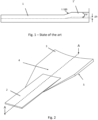
- Figure 1 shows the transition of varying thicknesses of composite laminates.
- the most used transition in the state of the art raises a laminate of thickness (1) to a laminate of thickness (1'), which represents a transition of 1:100.
- the increase in height ( ⁇ h) produces a moment (M).
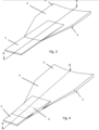
- Figure 2 shows the specific embodiment of a modular blade.
- it is an overlapping union of a cap (2) and a preform (3).
- the object of the invention is also valid for manufacturing with a thickening of the cap without the need to use a preform.
- the laminate of this union has a pocket face (4) which is the face of the laminate towards the interior of the blade and a mould face (5) which is the aerodynamic surface of the blade.
Landscapes
- Engineering & Computer Science (AREA)
- Chemical & Material Sciences (AREA)
- Materials Engineering (AREA)
- Mechanical Engineering (AREA)
- General Engineering & Computer Science (AREA)
- Life Sciences & Earth Sciences (AREA)
- Composite Materials (AREA)
- Wood Science & Technology (AREA)
- Sustainable Development (AREA)
- Sustainable Energy (AREA)
- Combustion & Propulsion (AREA)
- Laminated Bodies (AREA)
Claims (7)
- Modulares Rotorblatt für eine Windkraftanlage, umfassend einen Verbundwerkstofflaminat, dadurch gekennzeichnet, dass:- das Verbundlaminat im Bereich der Blattverbindung einen longitudinalen Dickenübergang aufweist, welcher als Anpassungsgefälle zwischen der ursprünglichen Dicke des Blatpanels und der zur Integration der Verbindung erforderlichen Dicke ausgebildet ist, wodurch der Dickenunterschied zwischen beiden Bereichen aufgenommen wird, und- das Verbundmaterial ein Laminat/Kern aus nicht-strukturellem Material (10) enthält, das am unteren Teil des Verbindungsstücks des Blatts, auf der Formseite (5), angeordnet ist, wobei diese Anordnung die Lage des Schwerpunkts des Laminats zwischen dem ursprünglichen Bereich des Blatpanels und dem Verbindungsbereich ausrichtet und geometrische Gradienten verringert, die unerwünschte Spannungs-konzentrationen verursachen.
- Modulares Rotorblatt nach Anspruch 1 mit einem Dickenübergang aus variablen Lagenstärken des Verbundlaminats, wobei das nicht-strukturelle Material (10) ein Laminat mit niedrigem Elastizitätsmodul (biaxial oder unidirektional bei 90º) oder ein Kern aus Schaumstoff, Balsaholz oder ähnlichem ist.
- Modulares Rotorblatt nach Anspruch 1 mit einem Dickenübergang aus variablen Lagenstärken des Verbundmaterials, wobei das nicht-strukturelle Material (10) die gesamte Breite der Basis des behandelten Verbundmaterials abdeckt und dessen vertikaler Schnitt dreieckig oder trapezförmig ausgebildet sein kann, um den Schwerpunkt anzuheben.
- Modulares Rotorblatt nach Anspruch 1 mit einem Dickenübergang aus variablen Lagenstärken des Verbundmaterials, wobei das nicht-strukturelle Material (10) als vorgehärtetes oder frisches Laminat in das Laminat integriert ist, im Fall der Verwendung von Laminaten mit niedrigem Modul.
- Modulares Rotorblatt nach Anspruch 4 mit einem Dickenübergang aus variablen Lagenstärken des Verbundmaterials, wobei das nicht-strukturelle Material (10) als eine der ersten Lagen des vorgefertigten Laminatpakets eingebracht ist, im Fall eines Schaumkerns, Balsaholzes oder ähnlichem.
- Modulares Rotorblatt nach Anspruch 1 mit einem Dickenübergang aus variablen Lagenstärken des Verbundmaterials, wobei der Bereich des nicht-strukturellen Materials (10) durch Modifikation der aerodynamischen Oberfläche des Blatts erzielt wird, ohne zusätzliches Material hinzuzufügen.
- Modulares Rotorblatt nach Anspruch 1 mit einem Dickenübergang aus variablen Lagenstärken des Verbundmaterials, wobei die innere Struktur des Blatts, insbesondere die Klebefugen, sowohl von innen als auch von außen inspizierbar ist, da das nicht-strukturelle Material (10) eine ausreichende Dichte für die Durchlässigkeit von Ultraschall aufweist.
Applications Claiming Priority (1)
| Application Number | Priority Date | Filing Date | Title |
|---|---|---|---|
| PCT/ES2021/070579 WO2023007038A1 (es) | 2021-07-29 | 2021-07-29 | Transicion de espesores variables de laminados de material compuesto de una pala modular |
Publications (4)
| Publication Number | Publication Date |
|---|---|
| EP4379205A1 EP4379205A1 (de) | 2024-06-05 |
| EP4379205A4 EP4379205A4 (de) | 2024-11-13 |
| EP4379205B1 true EP4379205B1 (de) | 2025-07-09 |
| EP4379205C0 EP4379205C0 (de) | 2025-07-09 |
Family
ID=85087625
Family Applications (1)
| Application Number | Title | Priority Date | Filing Date |
|---|---|---|---|
| EP21951728.1A Active EP4379205B1 (de) | 2021-07-29 | 2021-07-29 | Übergang von verbundmateriallaminaten mit variabler dicke einer modularen schaufel |
Country Status (6)
| Country | Link |
|---|---|
| US (1) | US20250074030A1 (de) |
| EP (1) | EP4379205B1 (de) |
| CN (1) | CN117881883A (de) |
| AU (1) | AU2021458504A1 (de) |
| ES (1) | ES3037638T3 (de) |
| WO (1) | WO2023007038A1 (de) |
Family Cites Families (10)
| Publication number | Priority date | Publication date | Assignee | Title |
|---|---|---|---|---|
| EP1486415A1 (de) | 2003-06-12 | 2004-12-15 | SSP Technology A/S | Windturbinenflügel und Verfahren zur Herstellung einer Turbinenflügelwurzel |
| DK2358998T3 (en) * | 2008-12-05 | 2017-10-30 | Vestas Wind Sys As | EFFICIENT WINDOWS, WINDOWS, AND ASSOCIATED SYSTEMS AND PROCEDURES FOR MANUFACTURING, INSTALLING AND USING |
| US20140271217A1 (en) * | 2013-03-15 | 2014-09-18 | Modular Wind Energy, Inc. | Efficient wind turbine blade design and associated manufacturing methods using rectangular spars and segmented shear web |
| ES2683273T3 (es) * | 2013-07-12 | 2018-09-25 | Lm Wind Power International Technology Ii Aps | Método y herramientas para fabricar una pala de aerogenerador |
| GB201509991D0 (en) * | 2015-06-09 | 2015-07-22 | Vestas Wind Sys As | Modular wind turbine blades |
| US20180051672A1 (en) * | 2016-08-19 | 2018-02-22 | General Electric Company | Jointed rotor blade for wind turbine |
| US10920743B2 (en) * | 2017-08-17 | 2021-02-16 | General Electric Company | Misaligned spar cap scarf joint connection |
| US11396154B2 (en) * | 2017-12-21 | 2022-07-26 | Vestas Wind Systems A/S | Modular wind turbine blade and associated method of manufacture |
| ES2876420T3 (es) * | 2018-04-05 | 2021-11-12 | Siemens Gamesa Renewable Energy As | Tira compuesta fibrosa pultruida con extremos ahusados en ancho y grosor para tapas de larguero de turbinas eólicas |
| DK3870834T3 (da) | 2018-10-25 | 2024-09-30 | Lm Wind Power As | Bjælkeflangekonstruktion til en sammenføjet vindmøllevinge |
-
2021
- 2021-07-29 EP EP21951728.1A patent/EP4379205B1/de active Active
- 2021-07-29 AU AU2021458504A patent/AU2021458504A1/en active Pending
- 2021-07-29 US US18/293,141 patent/US20250074030A1/en active Pending
- 2021-07-29 ES ES21951728T patent/ES3037638T3/es active Active
- 2021-07-29 CN CN202180101928.7A patent/CN117881883A/zh active Pending
- 2021-07-29 WO PCT/ES2021/070579 patent/WO2023007038A1/es not_active Ceased
Also Published As
| Publication number | Publication date |
|---|---|
| AU2021458504A1 (en) | 2024-02-15 |
| CN117881883A (zh) | 2024-04-12 |
| WO2023007038A1 (es) | 2023-02-02 |
| US20250074030A1 (en) | 2025-03-06 |
| EP4379205C0 (de) | 2025-07-09 |
| ES3037638T3 (en) | 2025-10-03 |
| EP4379205A4 (de) | 2024-11-13 |
| EP4379205A1 (de) | 2024-06-05 |
Similar Documents
| Publication | Publication Date | Title |
|---|---|---|
| EP2153979B1 (de) | Aus verbundwerkstoff hergestellter torsionskasten mit mehreren holmen | |
| EP2487106B1 (de) | Verbundstoffmaterialstruktur, sowie flugzeugtragfläche und damit ausgestatteter flugzeugrumpf | |
| EP2139761B1 (de) | Verfahren und systeme für verbundfachwerk | |
| CN101589227B (zh) | 用于风力涡轮机的加强叶片 | |
| EP2591229B1 (de) | Verbundfuge mit dezimierter kerbe | |
| EP2376328B1 (de) | Tragflächenaufbau mit gewelltem verstärkungsteil | |
| CN102066747A (zh) | 具有成角度的梁的风力涡轮机叶片 | |
| EP3077194B1 (de) | Zusammengefügte und anpassbare verbundanordnung | |
| US9701391B2 (en) | Aircraft structure comprising a skin panel | |
| CN101878367A (zh) | 风车翼及使用该风车翼的风力发电装置 | |
| US11994100B2 (en) | Manufacturing of segmented wind turbine blade | |
| KR20110100192A (ko) | 풍력 터빈 날개 및 이를 사용하는 풍력 터빈 발전장치 | |
| US11009008B2 (en) | Canopy structure and a wind turbine | |
| US20150252780A1 (en) | Wind turbine blade spar web having enhanced buckling strength | |
| US12049865B2 (en) | Wind turbine blade with a plurality of shear webs | |
| JP2019038517A (ja) | 共硬化した桁および縦通材の中央ウイングボックス | |
| WO2022099922A1 (zh) | 腹板及其成型方法、腹板组件及其成型方法、叶片以及风力发电机组 | |
| CN111630267B (zh) | 用于风力涡轮机的分段式叶片、分段式叶片的连接梁和端肋以及制造连接梁和端肋的方法 | |
| EP4379205A1 (de) | Übergang von verbundmateriallaminaten mit variabler dicke einer modularen schaufel | |
| US20240254960A1 (en) | Manufacturing of segmented wind turbine blade | |
| CN222141431U (zh) | 风力发电机组的叶片和风力发电机组 | |
| JP2020176538A (ja) | 風車ブレード及び風力発電システム | |
| Collier et al. | Ares V interstage composite panel concept and ringframe spacing trade studies | |
| EP4453409B1 (de) | Modulare windturbinenschaufel | |
| EP4634518A1 (de) | Windturbinenschaufel |
Legal Events
| Date | Code | Title | Description |
|---|---|---|---|
| STAA | Information on the status of an ep patent application or granted ep patent |
Free format text: STATUS: THE INTERNATIONAL PUBLICATION HAS BEEN MADE |
|
| PUAI | Public reference made under article 153(3) epc to a published international application that has entered the european phase |
Free format text: ORIGINAL CODE: 0009012 |
|
| STAA | Information on the status of an ep patent application or granted ep patent |
Free format text: STATUS: REQUEST FOR EXAMINATION WAS MADE |
|
| 17P | Request for examination filed |
Effective date: 20240205 |
|
| AK | Designated contracting states |
Kind code of ref document: A1 Designated state(s): AL AT BE BG CH CY CZ DE DK EE ES FI FR GB GR HR HU IE IS IT LI LT LU LV MC MK MT NL NO PL PT RO RS SE SI SK SM TR |
|
| STAA | Information on the status of an ep patent application or granted ep patent |
Free format text: STATUS: EXAMINATION IS IN PROGRESS |
|
| DAV | Request for validation of the european patent (deleted) | ||
| DAX | Request for extension of the european patent (deleted) | ||
| A4 | Supplementary search report drawn up and despatched |
Effective date: 20241016 |
|
| RIC1 | Information provided on ipc code assigned before grant |
Ipc: F03D 1/06 20060101AFI20241010BHEP |
|
| 17Q | First examination report despatched |
Effective date: 20241028 |
|
| RAP3 | Party data changed (applicant data changed or rights of an application transferred) |
Owner name: NABRAWIND TECHNOLOGIES, S.L. |
|
| GRAP | Despatch of communication of intention to grant a patent |
Free format text: ORIGINAL CODE: EPIDOSNIGR1 |
|
| STAA | Information on the status of an ep patent application or granted ep patent |
Free format text: STATUS: GRANT OF PATENT IS INTENDED |
|
| GRAS | Grant fee paid |
Free format text: ORIGINAL CODE: EPIDOSNIGR3 |
|
| GRAA | (expected) grant |
Free format text: ORIGINAL CODE: 0009210 |
|
| STAA | Information on the status of an ep patent application or granted ep patent |
Free format text: STATUS: THE PATENT HAS BEEN GRANTED |
|
| INTG | Intention to grant announced |
Effective date: 20250508 |
|
| AK | Designated contracting states |
Kind code of ref document: B1 Designated state(s): AL AT BE BG CH CY CZ DE DK EE ES FI FR GB GR HR HU IE IS IT LI LT LU LV MC MK MT NL NO PL PT RO RS SE SI SK SM TR |
|
| REG | Reference to a national code |
Ref country code: GB Ref legal event code: FG4D |
|
| REG | Reference to a national code |
Ref country code: CH Ref legal event code: EP |
|
| REG | Reference to a national code |
Ref country code: IE Ref legal event code: FG4D |
|
| REG | Reference to a national code |
Ref country code: DE Ref legal event code: R096 Ref document number: 602021034013 Country of ref document: DE |
|
| U01 | Request for unitary effect filed |
Effective date: 20250710 |
|
| U07 | Unitary effect registered |
Designated state(s): AT BE BG DE DK EE FI FR IT LT LU LV MT NL PT RO SE SI Effective date: 20250717 |
|
| U20 | Renewal fee for the european patent with unitary effect paid |
Year of fee payment: 5 Effective date: 20250714 |
|
| REG | Reference to a national code |
Ref country code: ES Ref legal event code: FG2A Ref document number: 3037638 Country of ref document: ES Kind code of ref document: T3 Effective date: 20251003 |
|
| PGFP | Annual fee paid to national office [announced via postgrant information from national office to epo] |
Ref country code: ES Payment date: 20250804 Year of fee payment: 5 |
|
| PG25 | Lapsed in a contracting state [announced via postgrant information from national office to epo] |
Ref country code: IS Free format text: LAPSE BECAUSE OF FAILURE TO SUBMIT A TRANSLATION OF THE DESCRIPTION OR TO PAY THE FEE WITHIN THE PRESCRIBED TIME-LIMIT Effective date: 20251109 |
|
| PG25 | Lapsed in a contracting state [announced via postgrant information from national office to epo] |
Ref country code: NO Free format text: LAPSE BECAUSE OF FAILURE TO SUBMIT A TRANSLATION OF THE DESCRIPTION OR TO PAY THE FEE WITHIN THE PRESCRIBED TIME-LIMIT Effective date: 20251009 |
|
| PG25 | Lapsed in a contracting state [announced via postgrant information from national office to epo] |
Ref country code: HR Free format text: LAPSE BECAUSE OF FAILURE TO SUBMIT A TRANSLATION OF THE DESCRIPTION OR TO PAY THE FEE WITHIN THE PRESCRIBED TIME-LIMIT Effective date: 20250709 |
|
| PG25 | Lapsed in a contracting state [announced via postgrant information from national office to epo] |
Ref country code: GR Free format text: LAPSE BECAUSE OF FAILURE TO SUBMIT A TRANSLATION OF THE DESCRIPTION OR TO PAY THE FEE WITHIN THE PRESCRIBED TIME-LIMIT Effective date: 20251010 |
|
| PG25 | Lapsed in a contracting state [announced via postgrant information from national office to epo] |
Ref country code: PL Free format text: LAPSE BECAUSE OF FAILURE TO SUBMIT A TRANSLATION OF THE DESCRIPTION OR TO PAY THE FEE WITHIN THE PRESCRIBED TIME-LIMIT Effective date: 20250709 |
|
| PG25 | Lapsed in a contracting state [announced via postgrant information from national office to epo] |
Ref country code: RS Free format text: LAPSE BECAUSE OF FAILURE TO SUBMIT A TRANSLATION OF THE DESCRIPTION OR TO PAY THE FEE WITHIN THE PRESCRIBED TIME-LIMIT Effective date: 20251009 |
|
| REG | Reference to a national code |
Ref country code: CH Ref legal event code: H13 Free format text: ST27 STATUS EVENT CODE: U-0-0-H10-H13 (AS PROVIDED BY THE NATIONAL OFFICE) Effective date: 20260224 |
|
| PG25 | Lapsed in a contracting state [announced via postgrant information from national office to epo] |
Ref country code: SM Free format text: LAPSE BECAUSE OF FAILURE TO SUBMIT A TRANSLATION OF THE DESCRIPTION OR TO PAY THE FEE WITHIN THE PRESCRIBED TIME-LIMIT Effective date: 20250709 |
|
| PG25 | Lapsed in a contracting state [announced via postgrant information from national office to epo] |
Ref country code: CH Free format text: LAPSE BECAUSE OF NON-PAYMENT OF DUE FEES Effective date: 20250731 Ref country code: CZ Free format text: LAPSE BECAUSE OF FAILURE TO SUBMIT A TRANSLATION OF THE DESCRIPTION OR TO PAY THE FEE WITHIN THE PRESCRIBED TIME-LIMIT Effective date: 20250709 |
|
| PG25 | Lapsed in a contracting state [announced via postgrant information from national office to epo] |
Ref country code: SK Free format text: LAPSE BECAUSE OF FAILURE TO SUBMIT A TRANSLATION OF THE DESCRIPTION OR TO PAY THE FEE WITHIN THE PRESCRIBED TIME-LIMIT Effective date: 20250709 |
|
| PLBE | No opposition filed within time limit |
Free format text: ORIGINAL CODE: 0009261 |
|
| STAA | Information on the status of an ep patent application or granted ep patent |
Free format text: STATUS: NO OPPOSITION FILED WITHIN TIME LIMIT |