EP4378847A1 - Liquid container and liquid container with content liquid - Google Patents
Liquid container and liquid container with content liquid Download PDFInfo
- Publication number
- EP4378847A1 EP4378847A1 EP22849116.3A EP22849116A EP4378847A1 EP 4378847 A1 EP4378847 A1 EP 4378847A1 EP 22849116 A EP22849116 A EP 22849116A EP 4378847 A1 EP4378847 A1 EP 4378847A1
- Authority
- EP
- European Patent Office
- Prior art keywords
- liquid
- nozzle
- tube
- recovery channel
- wall
- Prior art date
- Legal status (The legal status is an assumption and is not a legal conclusion. Google has not performed a legal analysis and makes no representation as to the accuracy of the status listed.)
- Pending
Links
Images










Classifications
-
- B—PERFORMING OPERATIONS; TRANSPORTING
- B65—CONVEYING; PACKING; STORING; HANDLING THIN OR FILAMENTARY MATERIAL
- B65D—CONTAINERS FOR STORAGE OR TRANSPORT OF ARTICLES OR MATERIALS, e.g. BAGS, BARRELS, BOTTLES, BOXES, CANS, CARTONS, CRATES, DRUMS, JARS, TANKS, HOPPERS, FORWARDING CONTAINERS; ACCESSORIES, CLOSURES, OR FITTINGS THEREFOR; PACKAGING ELEMENTS; PACKAGES
- B65D23/00—Details of bottles or jars not otherwise provided for
- B65D23/06—Integral drip catchers or drip-preventing means
-
- B—PERFORMING OPERATIONS; TRANSPORTING
- B29—WORKING OF PLASTICS; WORKING OF SUBSTANCES IN A PLASTIC STATE IN GENERAL
- B29C—SHAPING OR JOINING OF PLASTICS; SHAPING OF MATERIAL IN A PLASTIC STATE, NOT OTHERWISE PROVIDED FOR; AFTER-TREATMENT OF THE SHAPED PRODUCTS, e.g. REPAIRING
- B29C49/00—Blow-moulding, i.e. blowing a preform or parison to a desired shape within a mould; Apparatus therefor
- B29C49/071—Preforms or parisons characterised by their configuration, e.g. geometry, dimensions or physical properties
-
- B—PERFORMING OPERATIONS; TRANSPORTING
- B65—CONVEYING; PACKING; STORING; HANDLING THIN OR FILAMENTARY MATERIAL
- B65D—CONTAINERS FOR STORAGE OR TRANSPORT OF ARTICLES OR MATERIALS, e.g. BAGS, BARRELS, BOTTLES, BOXES, CANS, CARTONS, CRATES, DRUMS, JARS, TANKS, HOPPERS, FORWARDING CONTAINERS; ACCESSORIES, CLOSURES, OR FITTINGS THEREFOR; PACKAGING ELEMENTS; PACKAGES
- B65D1/00—Rigid or semi-rigid containers having bodies formed in one piece, e.g. by casting metallic material, by moulding plastics, by blowing vitreous material, by throwing ceramic material, by moulding pulped fibrous material or by deep-drawing operations performed on sheet material
- B65D1/02—Bottles or similar containers with necks or like restricted apertures, designed for pouring contents
- B65D1/0223—Bottles or similar containers with necks or like restricted apertures, designed for pouring contents characterised by shape
- B65D1/023—Neck construction
-
- B—PERFORMING OPERATIONS; TRANSPORTING
- B65—CONVEYING; PACKING; STORING; HANDLING THIN OR FILAMENTARY MATERIAL
- B65D—CONTAINERS FOR STORAGE OR TRANSPORT OF ARTICLES OR MATERIALS, e.g. BAGS, BARRELS, BOTTLES, BOXES, CANS, CARTONS, CRATES, DRUMS, JARS, TANKS, HOPPERS, FORWARDING CONTAINERS; ACCESSORIES, CLOSURES, OR FITTINGS THEREFOR; PACKAGING ELEMENTS; PACKAGES
- B65D1/00—Rigid or semi-rigid containers having bodies formed in one piece, e.g. by casting metallic material, by moulding plastics, by blowing vitreous material, by throwing ceramic material, by moulding pulped fibrous material or by deep-drawing operations performed on sheet material
- B65D1/02—Bottles or similar containers with necks or like restricted apertures, designed for pouring contents
- B65D1/0223—Bottles or similar containers with necks or like restricted apertures, designed for pouring contents characterised by shape
- B65D1/023—Neck construction
- B65D1/0246—Closure retaining means, e.g. beads, screw-threads
-
- B—PERFORMING OPERATIONS; TRANSPORTING
- B65—CONVEYING; PACKING; STORING; HANDLING THIN OR FILAMENTARY MATERIAL
- B65D—CONTAINERS FOR STORAGE OR TRANSPORT OF ARTICLES OR MATERIALS, e.g. BAGS, BARRELS, BOTTLES, BOXES, CANS, CARTONS, CRATES, DRUMS, JARS, TANKS, HOPPERS, FORWARDING CONTAINERS; ACCESSORIES, CLOSURES, OR FITTINGS THEREFOR; PACKAGING ELEMENTS; PACKAGES
- B65D25/00—Details of other kinds or types of rigid or semi-rigid containers
- B65D25/38—Devices for discharging contents
- B65D25/40—Nozzles or spouts
- B65D25/42—Integral or attached nozzles or spouts
-
- B—PERFORMING OPERATIONS; TRANSPORTING
- B65—CONVEYING; PACKING; STORING; HANDLING THIN OR FILAMENTARY MATERIAL
- B65D—CONTAINERS FOR STORAGE OR TRANSPORT OF ARTICLES OR MATERIALS, e.g. BAGS, BARRELS, BOTTLES, BOXES, CANS, CARTONS, CRATES, DRUMS, JARS, TANKS, HOPPERS, FORWARDING CONTAINERS; ACCESSORIES, CLOSURES, OR FITTINGS THEREFOR; PACKAGING ELEMENTS; PACKAGES
- B65D25/00—Details of other kinds or types of rigid or semi-rigid containers
- B65D25/54—Inspection openings or windows
-
- B—PERFORMING OPERATIONS; TRANSPORTING
- B65—CONVEYING; PACKING; STORING; HANDLING THIN OR FILAMENTARY MATERIAL
- B65D—CONTAINERS FOR STORAGE OR TRANSPORT OF ARTICLES OR MATERIALS, e.g. BAGS, BARRELS, BOTTLES, BOXES, CANS, CARTONS, CRATES, DRUMS, JARS, TANKS, HOPPERS, FORWARDING CONTAINERS; ACCESSORIES, CLOSURES, OR FITTINGS THEREFOR; PACKAGING ELEMENTS; PACKAGES
- B65D41/00—Caps, e.g. crown caps or crown seals, i.e. members having parts arranged for engagement with the external periphery of a neck or wall defining a pouring opening or discharge aperture; Protective cap-like covers for closure members, e.g. decorative covers of metal foil or paper
- B65D41/32—Caps or cap-like covers with lines of weakness, tearing-strips, tags, or like opening or removal devices, e.g. to facilitate formation of pouring openings
- B65D41/56—Caps or cap-like covers serving as, or incorporating, drinking or measuring vessels
- B65D41/565—Caps or cap-like covers serving as, or incorporating, drinking or measuring vessels with integral internal sealing means
-
- B—PERFORMING OPERATIONS; TRANSPORTING
- B65—CONVEYING; PACKING; STORING; HANDLING THIN OR FILAMENTARY MATERIAL
- B65D—CONTAINERS FOR STORAGE OR TRANSPORT OF ARTICLES OR MATERIALS, e.g. BAGS, BARRELS, BOTTLES, BOXES, CANS, CARTONS, CRATES, DRUMS, JARS, TANKS, HOPPERS, FORWARDING CONTAINERS; ACCESSORIES, CLOSURES, OR FITTINGS THEREFOR; PACKAGING ELEMENTS; PACKAGES
- B65D47/00—Closures with filling and discharging, or with discharging, devices
- B65D47/04—Closures with discharging devices other than pumps
- B65D47/06—Closures with discharging devices other than pumps with pouring spouts or tubes; with discharge nozzles or passages
- B65D47/12—Closures with discharging devices other than pumps with pouring spouts or tubes; with discharge nozzles or passages having removable closures
- B65D47/122—Threaded caps
-
- B—PERFORMING OPERATIONS; TRANSPORTING
- B29—WORKING OF PLASTICS; WORKING OF SUBSTANCES IN A PLASTIC STATE IN GENERAL
- B29C—SHAPING OR JOINING OF PLASTICS; SHAPING OF MATERIAL IN A PLASTIC STATE, NOT OTHERWISE PROVIDED FOR; AFTER-TREATMENT OF THE SHAPED PRODUCTS, e.g. REPAIRING
- B29C2949/00—Indexing scheme relating to blow-moulding
- B29C2949/07—Preforms or parisons characterised by their configuration
- B29C2949/0715—Preforms or parisons characterised by their configuration the preform having one end closed
-
- B—PERFORMING OPERATIONS; TRANSPORTING
- B29—WORKING OF PLASTICS; WORKING OF SUBSTANCES IN A PLASTIC STATE IN GENERAL
- B29C—SHAPING OR JOINING OF PLASTICS; SHAPING OF MATERIAL IN A PLASTIC STATE, NOT OTHERWISE PROVIDED FOR; AFTER-TREATMENT OF THE SHAPED PRODUCTS, e.g. REPAIRING
- B29C2949/00—Indexing scheme relating to blow-moulding
- B29C2949/07—Preforms or parisons characterised by their configuration
- B29C2949/076—Preforms or parisons characterised by their configuration characterised by the shape
- B29C2949/0768—Preforms or parisons characterised by their configuration characterised by the shape characterised by the shape of specific parts of preform
- B29C2949/077—Preforms or parisons characterised by their configuration characterised by the shape characterised by the shape of specific parts of preform characterised by the neck
-
- B—PERFORMING OPERATIONS; TRANSPORTING
- B29—WORKING OF PLASTICS; WORKING OF SUBSTANCES IN A PLASTIC STATE IN GENERAL
- B29C—SHAPING OR JOINING OF PLASTICS; SHAPING OF MATERIAL IN A PLASTIC STATE, NOT OTHERWISE PROVIDED FOR; AFTER-TREATMENT OF THE SHAPED PRODUCTS, e.g. REPAIRING
- B29C2949/00—Indexing scheme relating to blow-moulding
- B29C2949/07—Preforms or parisons characterised by their configuration
- B29C2949/076—Preforms or parisons characterised by their configuration characterised by the shape
- B29C2949/0768—Preforms or parisons characterised by their configuration characterised by the shape characterised by the shape of specific parts of preform
- B29C2949/0778—Preforms or parisons characterised by their configuration characterised by the shape characterised by the shape of specific parts of preform characterised by the flange
-
- B—PERFORMING OPERATIONS; TRANSPORTING
- B29—WORKING OF PLASTICS; WORKING OF SUBSTANCES IN A PLASTIC STATE IN GENERAL
- B29C—SHAPING OR JOINING OF PLASTICS; SHAPING OF MATERIAL IN A PLASTIC STATE, NOT OTHERWISE PROVIDED FOR; AFTER-TREATMENT OF THE SHAPED PRODUCTS, e.g. REPAIRING
- B29C2949/00—Indexing scheme relating to blow-moulding
- B29C2949/07—Preforms or parisons characterised by their configuration
- B29C2949/079—Auxiliary parts or inserts
- B29C2949/0794—Dispensing spout
-
- B—PERFORMING OPERATIONS; TRANSPORTING
- B29—WORKING OF PLASTICS; WORKING OF SUBSTANCES IN A PLASTIC STATE IN GENERAL
- B29C—SHAPING OR JOINING OF PLASTICS; SHAPING OF MATERIAL IN A PLASTIC STATE, NOT OTHERWISE PROVIDED FOR; AFTER-TREATMENT OF THE SHAPED PRODUCTS, e.g. REPAIRING
- B29C49/00—Blow-moulding, i.e. blowing a preform or parison to a desired shape within a mould; Apparatus therefor
- B29C49/08—Biaxial stretching during blow-moulding
- B29C49/10—Biaxial stretching during blow-moulding using mechanical means for prestretching
-
- B—PERFORMING OPERATIONS; TRANSPORTING
- B29—WORKING OF PLASTICS; WORKING OF SUBSTANCES IN A PLASTIC STATE IN GENERAL
- B29L—INDEXING SCHEME ASSOCIATED WITH SUBCLASS B29C, RELATING TO PARTICULAR ARTICLES
- B29L2031/00—Other particular articles
- B29L2031/712—Containers; Packaging elements or accessories, Packages
- B29L2031/7158—Bottles
Definitions
- This disclosure relates to a liquid container including a container body and a nozzle, and a liquid container with content liquid.
- liquid containers that contain content liquid with relatively high viscosity such as liquid laundry detergent or fabric softener
- liquid containers that include a nozzle at an opening of a container body with an accommodation space for content liquid and a nozzle cap attached thereto are known (see, for example, Patent Literature (PTL) 1).
- the nozzle is generally formed in the shape of a gutter, supported by a bulkhead of the nozzle cap, and disposed so that its tip protrudes outward from a tip opening of the nozzle cap. This allows the content liquid to be easily poured out through the nozzle to a targeted position.
- the disclosure aims to solve such a problem. It would be helpful to provide a liquid container and a liquid container with content liquid that are easy to sort and dispose of, while preventing dripping of the liquid from a nozzle to the outside.
- a liquid container according to the disclosure is
- a liquid container and a liquid container with content liquid that are easy to sort and dispose of, while preventing dripping of the liquid from a nozzle to the outside.
- a liquid container 100 according to a first embodiment of the disclosure illustrated in FIG. 1 is suitable for containing content liquid with relatively high viscosity, such as, for example, liquid laundry detergent or fabric softener, and has a container body 10, a nozzle 20, and an outer tube 30.
- content liquid with relatively high viscosity such as, for example, liquid laundry detergent or fabric softener
- the side on which the nozzle 20 is located is referred to as an upper side (upper side in FIG. 1 )
- the side on which a bottom portion 12 of the container body 10 is located is referred to as a lower side (lower side in FIG. 1 ).
- a radial outside is referred to as a direction away from the central axis O of the liquid container 100 extending in a vertical direction in FIG.
- the central axis O in FIG. 1 is used to define the radial outside and the radial inside, and does not mean that every component of the liquid container 100 in the present embodiment is always formed axisymmetrically around this central axis O.
- integral molding means one molded as a single piece with a die, including one molded as a single piece by insert molding, two-color molding, or the like, but does not include one that is made by integrating separate members molded with separate dies in a subsequent process that does not involve resin molding such as adhesion.
- the container body 10 is formed in the shape of a bottle with a body portion 11 that compartmentally forms an accommodation space S for the content liquid inside, the bottom portion 12 that closes a lower end of the body portion 11, and a cylindrical opening portion 15 that is connected to an upper end of the body portion 11 via a shoulder portion 13, so that the content liquid (not illustrated) can be contained in the accommodation space S.
- the container body 10 can be made of synthetic resin, such as polyethylene (PE), polypropylene (PP), polystyrene (PS), or polyethylene terephthalate (PET).
- the opening portion 15 is not limited to a cylindrical shape, but can be formed in other shapes as long as the opening portion 15 is tubular, such as an oval tubular or square tubular.
- the nozzle 20 is integrally molded with the container body 10 so as to be connected to an upper end of the opening portion 15 of the container body 10.
- the nozzle 20 is formed in the shape of the letter C in cross section, i.e. the shape of a gutter, with a notch 22 extending from one end to the other end along an axial direction at one circumferential point of an approximately cylindrical tube wall 21, and a beveled portion 23 is formed at a circumferential edge forming the notch 22 at an upper portion of the tube wall 21.
- This configuration allows the content liquid contained in the accommodation space S of the container body 10 to be easily poured out at a desired position through the nozzle 20.
- the nozzle 20 protrudes upward from the upper end of the opening portion 15 and is formed of the same synthetic resin material as the container body 10.
- a tip of the nozzle 20 is not limited to the shape with the inclined beveled portion 23, but can be of various shapes, such as a shape cut to be rounded when viewed from the side.
- An outer tube 30 to attach a cap 40 is provided on the radial outside of the nozzle 20 (see FIG. 4 ).
- the outer tube 30 is integrally molded with the container body 10 so as to be connected to the upper end of the opening portion 15 of the container body 10.
- the outer tube 30 includes an approximately cylindrical peripheral wall 31, an annular neck ring 32 protruding radially outward at a lower portion of the peripheral wall 31, and a bottom wall 33 inclined radially inward and downward from a lower end of the peripheral wall 31.
- An inner peripheral edge of the bottom wall 33 is connected to the upper end of the opening portion 15 of the container body 10.
- the container body 10, the nozzle 20, and the outer tube 30 are integrally molded of the same synthetic resin material.
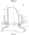
- the area enclosed by the tube wall 21 of the nozzle 20, the peripheral wall 31 of the outer tube 30, and the bottom wall 33 of the outer tube 30 functions as a liquid recovery channel R that returns the content liquid that has leaked to the radial outside of the nozzle 20 into the accommodation space S.
- the bottom wall 33 extending radially inward and downward from the lower end of the peripheral wall 31 of the outer tube 30 functions as a bottom wall 33 of the liquid recovery channel R.
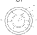
- FIGS. 2 and 3 An upper surface of the bottom wall 33 of the liquid recovery channel R is formed, in FIGS. 2 and 3 , so that a left end is the highest and a right end, at which the notch 22 is provided, is the lowest.
- the bottom wall 33 is inclined downward from the left end to the right end so as to be gradually lower along the channel.
- the liquid recovery channel R has two paths, one from the left end to the right end clockwise along the channel and the other from the left end to the right end counterclockwise along the channel. In either path, the upper surface of the bottom wall 33 is inclined so as to be gradually lower from the left end to the right end.
- the upper surface of the bottom wall 33 of the liquid recovery channel R is formed spirally over a half-circumference from the left end to the right end.
- the bottom wall 33 is inclined downward from the radial outside to the radial inside at the same circumferential position.
- the upper surface of the bottom wall 33 gradually lowering from the left end to the right end in FIGS. 2 and 3 means that the upper surface of the bottom wall 33 gradually lowers from the left end to the right end at the same radial position (same widthwise position of the channel).
- a lower end of the notch 22 provided at one circumferential point of the nozzle 20 constitutes a connecting passage 35 that connects the liquid recovery channel R with the accommodation space S.
- the content liquid that has leaked to the radial outside of the nozzle 20 enters the liquid recovery channel R and moves to a low direction from the left end to the right end of the bottom wall 33 in FIGS. 2 and 3 .
- the content liquid that has moved within the liquid recovery channel R to the right end of the bottom wall 33 moves further radially inward, and is returned through the connecting passage 35 (see FIGS. 2 and 3 ) to the accommodation space S of the container body 10.
- the bottom wall 33 of the liquid recovery channel R is made thinner at an area excluding an outer edge portion 34 by providing a thinned portion 33a that is recessed upward from a lower surface of the bottom wall 33.
- the wall thickness of the bottom wall 33 at the area that is made thinner by wall-thinning is approximately constant in a direction along the channel.
- the thickness of the bottom wall 33 at the area that is made thinner by wall-thinning is also approximately constant in a radial direction.
- the thinned area in the bottom wall 33 of the liquid recovery channel R is, at the lower surface, as well as at the upper surface through which the content liquid flows, inclined downward from the left end to the right end of FIGS. 2 and 3 and downward radially inward.
- the thinned portion 33a in the bottom wall 33 of the liquid recovery channel R so that the thickness is configured to be made uniform at the thinned area especially in a circumferential direction, when a preform 200 (see FIG. 5 ) described below is integrally molded to manufacture the liquid container 100, a molten resin can easily flow evenly around an area corresponding to the bottom wall 133 in a die, which prevents the occurrence of a molding defect such as a sink mark. Note that, a configuration without providing the thinned portion 33a may be adopted.
- the lower surface of the bottom wall 33 may be configured to be tapered with approximately the same height in the circumferential direction, so that the thickness of the bottom wall 33 gradually becomes thinner in the circumferential direction.
- a lower surface of the outer edge portion 34 of the bottom wall 33 which is not provided with the thinned portion 33a, is configured to extend approximately horizontally over the circumferential direction.
- the lower surface of the outer edge portion 34 is formed to be of almost the same height regardless of circumferential position.
- an upper or lower surface of the neck ring 32 may be butted against the reference plane of the blow molding die to secure the preform 200.
- the bottom wall 33 is configured to be thinned at the area excluding the outer edge portion 34 and to be butted at the outer edge portion 34 against the reference plane of the blow molding die, but is not limited to this aspect.
- the bottom wall 33 may be configured to be thinned at an area excluding an inner edge portion and to be butted at the inner edge portion against the reference plane of the die.
- An outer peripheral surface of an upper portion of the peripheral wall 31 of the outer tube 30 is provided with a male thread 31a for attaching the cap 40 described below by screw engagement.
- a male thread 31a for attaching the cap 40 described below by screw engagement.
- an annular protrusion may be provided on the peripheral wall 31 for attaching the cap 40 by stopper engagement.
- the cap 40 includes an outer peripheral wall 41 that covers the nozzle 20 from the radial outside, a top wall 43 that closes an upper end of the outer peripheral wall 41, a flange portion 44 that protrudes radially outward from a lower end of the outer peripheral wall 41, an attachment tube 45 that hangs down from an outer edge of the flange portion 44, a sealing wall 46 that hangs down from a lower surface of the flange portion 44 on the radial inside of the attachment tube 45 and contacts an inner surface of the peripheral wall 31 for sealing in a liquid-tight manner, and an inner tube 47 that hangs down from the lower surface of the flange portion 44 on the radial inside of the sealing wall 46.
- a female thread 45a that is screwed into the male thread 31a formed in the peripheral wall 31 of the outer tube 30 is formed.
- the cap 40 plays the role of preventing the content liquid from leaking out of a nozzle opening 21a, which is compartmentally formed by the nozzle 20.
- the cap 40 can also function as a measuring cap by attaching a scale for measuring, indicated by ribbed projections or printing, for example, on the outer peripheral wall 41.
- the cap 40 can be made of transparent or translucent resin to facilitate measuring the content liquid.
- the liquid can be measured by using the cap 40 in a posture such that the top wall 43 of the cap 40, which is formed into a flat plate, is on a lower side and an opening of the cap 40 is on an upper side.
- the cap 40 is turned around the central axis O to release the screw engagement between the cap 40 and the outer tube 30 so that the cap 40 can be moved upward against the container body 10.
- the cap 40 can then be removed from the outer tube 30 by pulling the cap 40 upward with the screw engagement completely disengaged.
- the container body 10 With the cap 40 removed from the outer tube 30 and the nozzle 20 exposed, the container body 10 can be tilted from an upright position with the tip of the nozzle 20 facing upward to an inclined position with the notch 22 facing upward, in order to pour the content liquid out of the accommodation space S through the nozzle opening 21a from the tip of the nozzle 20. At this time, the content liquid in the accommodation space S of the container body 10 is guided along the nozzle 20, which is formed in the shape of a gutter, and is poured out from the tip of the nozzle 20.
- the nozzle 20 can be closed by attaching the cap 40 by screwing the female thread 45a of the cap 40 back into the male thread 31a of the outer tube 30.
- the preform 200 illustrated in FIG. 5 is integrally molded by injection molding or the like. Then, an outer edge portion 134 of a bottom wall 133 of the liquid recovery channel R is butted against the reference plane of the blow molding die so as to secure the preform 200 to the die, and biaxial stretch blow molding is performed.
- the preform 200 includes a main body 110 having the shape of a test tube, and a nozzle 120 and an outer tube 130 that are integrally molded at an upper end of the main body 110.
- the main body 110 includes a cylindrical body portion 111, and an approximately hemispherical bottom portion 112 that closes a lower end of the body portion 111.
- the main body 110 is a portion that forms the opening portion 15, the shoulder portion 13, the body portion 11, and the bottom portion 12 of the liquid container 100 by biaxial stretch blow molding of the preform 200, and has an interior space S2.
- the nozzle 120 and the outer tube 130 of the preform 200 have the same shapes as the nozzle 20 and the outer tube 30 of the liquid container 100, and are parts that do not expand during biaxial stretch blow molding.
- the nozzle 120 is formed in the shape of the letter C in cross section, i.e. the shape of a gutter, with a notch 122 extending from one end to the other end along an axial direction at one circumferential point of an approximately cylindrical tube wall 121, and a beveled portion 123 is formed at a circumferential edge forming the notch 122 at an upper portion of the tube wall 121.
- the outer tube 130 of the preform 200 includes an approximately cylindrical peripheral wall 131, an annular neck ring 132 protruding radially outward at a lower portion of the peripheral wall 131, and a bottom wall 133 inclined radially inward and downward from a lower end of the peripheral wall 131.
- An inner peripheral edge of the bottom wall 133 is connected to an upper end of the main body 110.
- the area enclosed by the tube wall 121 of the nozzle 120, the peripheral wall 131 of the outer tube 130, and the bottom wall 133 of the outer tube 130 forms the liquid recovery channel R.
- a thinned portion 133a that is recessed upward is formed in a lower surface of the bottom wall 133, and an outer edge portion 134 of the bottom wall 133, which is not thinned, extends to approximately the same height in a circumferential direction.
- the outer edge portion 134 of the bottom wall 133 of the preform 200 is butted against and secured to the reference plane of the blow molding die, and a pressurized fluid is supplied to the interior of the preform 200, while the main body 110 is stretched axially by a stretch rod, to perform biaxial stretch blow molding.
- the main body 110 is axially and radially stretched by blow molding to form the liquid container 100 by forming the opening portion 15, the shoulder portion 13, the body portion 11, and the bottom portion 12 illustrated in FIG. 1 .
- the liquid container 100 in which the container body 10, the nozzle 20, and the outer tube 30 are integrally molded can be formed by expanding only the main body 110 of the preform 200, in which the main body 110, the nozzle 120, and the outer tube 130 are integrally molded, by biaxial stretch blow molding. Since the liquid recovery channel R is compartmentally formed by the nozzle 20 and the outer tube 30, the liquid container 100 is a container in which the container body 10, the nozzle 20, and the liquid recovery channel R are integrally molded.
- the container body 10 that compartmentally forms the accommodation space S for the content liquid
- the cylindrical nozzle 20 that is connected to an upper portion of the container body 10 and guides the content liquid to the outside
- the liquid recovery channel R that returns the content liquid on the radial outside of the nozzle 20 into the accommodation space S are configured to be formed by integral molding.
- the liquid recovery channel R is configured to be inclined downward toward the circumferential direction, and the connecting passage 35 that connects the liquid recovery channel R with the accommodation space S is configured to be provided at the lower end of the liquid recovery channel R.
- the bottom wall 33 of the liquid recovery channel R is configured to have the thinned portion 33a that is recessed upward from the lower surface of the bottom wall 33, and the thickness of the bottom wall 33 at the area with the thinned portion is configured to be approximately constant in the direction along the channel.
- the bottom wall 33 of the liquid recovery channel R is configured to have the thinned portion 33a that is recessed upward from the lower surface of the bottom wall 33, and the area excluding the thinned portion 33a in the lower surface of the bottom wall 33 is configured to extend horizontally over the circumferential direction.
- the upper surface of the bottom wall 33 of the liquid recovery channel R is configured to be inclined downward from the radial outside to the radial inside.
- the outer tube 30 is configured to be formed on the radial outside of the nozzle 20, and the liquid recovery channel R is configured to be formed at a radial position between the nozzle 20 and the outer tube 30.
- liquid container 300 according to a second embodiment of the disclosure will be exemplarily described in more detail with reference to the drawings.
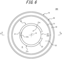
- the liquid container 300 according to the second embodiment of the disclosure illustrated in FIGS. 6 and 7 has a container body 10, a nozzle 20, and an outer tube 30.
- the definitions of "vertical direction”, “radial direction”, “central axis”, and “integrally molding” are the same as in the first embodiment, so further explanation here is omitted.
- a side on which an upper end of the nozzle 20 is located may be described as a tip side. Since the configuration of the container body 10 is the same as in the first embodiment, an illustration of an entire diagram of the liquid container 300, including a bottom portion 12 of the container body 10, is omitted. Components that have the same functions as in the first embodiment will be described with the same reference signs as in the first embodiment.
- the nozzle 20 is integrally molded with the container body 10 so as to be connected to an upper end of an opening portion 15 of the container body 10.
- the nozzle 20 is formed in the shape of the letter C in cross section, i.e. the shape of a gutter, with a notch 22 extending from one end to the other end along an axial direction at one circumferential point of a cylindrical tube wall 21.
- a beveled portion 23 that is cut to be rounded when viewed from the side is formed.
- This configuration allows content liquid contained in an accommodation space S of the container body 10 to be easily poured out at a desired position through the nozzle 20.
- the nozzle 20 protrudes upward from the upper end of the opening portion 15 and is formed of the same synthetic resin material as the container body 10.
- an outer peripheral surface 21c of the tube wall 21 is in the shape of an arc of a regular circle in plan view.
- the tube wall 21 is not in the shape of a perfect regular circle in plan view due to the provision of the notch 22, the tube wall 21 is in the shape of an arc, which is part of a regular circle.
- the outer peripheral surface 21c of the tube wall 21 may constitute a complete regular circle in plan view without the notch 22.
- the outer peripheral surface 21c of the tube wall 21 may have the same diameter from the bottom to the top as illustrated in the example in FIG. 7 , or may have a diameter that is reduced or expanded from the bottom to the top.
- the outer peripheral surface 21c of the tube wall 21 is located on a regular circle at all areas in plan view.
- the outer peripheral surface 21c of the tube wall 21 refers to an outer surface that extends in a circumferential direction in the tube wall 21.
- radially extending surfaces that are formed by the provision of the notch 22 are not included in the outer peripheral surface 21c of the tube wall 21.
- Conventional nozzles are configured so that the tip of the nozzle protrudes radially outward, allowing content liquid to be discharged at a desired position through the protruding portion.
- the outer peripheral surface 21c of the nozzle 20 is configured to be located on a regular circle in plan view in order to increase the accuracy of the liquid container 300, so the conventional configuration cannot be adopted. Therefore, in order to discharge the content liquid from the nozzle 20 to a desired position, a pouring groove 21b that guides the content liquid to the desired position is provided at part of an inner peripheral surface of the tube wall 21 of the nozzle 20 in the circumferential direction.
- the pouring groove 21b is provided at a circumferential position opposite the notch 22 in the inner peripheral surface of the tube wall 21 of the nozzle 20.
- the pouring groove 21b is recessed radially outward from the inner peripheral surface of the tube wall 21 as illustrated in FIGS. 6 and 7 , and extends to an upper end (tip) of the tube wall 21 as illustrated in FIG. 7 .
- the pouring groove 21b is configured so that the amount of a radially outward recess increases, as well as a circumferential width increases, as the pouring groove 21b nears the upper end.
- the pouring groove 21b is in the shape of an inverted triangular pyramid in which circumferential and radial widths increase as the pouring groove 21b nears the upper end.
- This configuration allows the content liquid that has been guided along the inner peripheral surface of the tube wall 21 to be gradually guided radially outward in the pouring groove 21b, thereby facilitating precisely discharging the liquid at the desired position. It can also provide good drainage when pouring out the content liquid.
- the tip of the nozzle 20 is not limited to the beveled portion 23 that is cut to be rounded when viewed from the side, but can be of various shapes, such as straight inclined beveled portions.
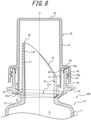
- the outer tube 30 for attaching a cap 40 (see FIG. 8 ) is provided on the radial outside of the nozzle 20, the outer tube 30 for attaching a cap 40 (see FIG. 8 ) is provided.
- the outer tube 30 is integrally molded with the container body 10 so as to be connected to the upper end of the opening portion 15 of the container body 10.
- the outer tube 30 includes an approximately cylindrical peripheral wall 31, an annular neck ring 32 protruding radially outward at a lower portion of the peripheral wall 31, and a bottom wall 33 inclined radially inward and downward from a lower end of the peripheral wall 31.
- An inner peripheral edge of the bottom wall 33 is connected to the upper end of the opening portion 15 of the container body 10.
- the container body 10, the nozzle 20, and the outer tube 30 are integrally molded of the same synthetic resin material.
- the area enclosed by the tube wall 21 of the nozzle 20, the peripheral wall 31 of the outer tube 30, and the bottom wall 33 of the outer tube 30 functions as a liquid recovery channel R that returns the content liquid that has leaked to the radial outside of the nozzle 20 into the accommodation space S.
- the bottom wall 33 extending radially inward and downward from the lower end of the peripheral wall 31 of the outer tube 30 functions as a bottom wall 33 of the liquid recovery channel R.
- the configuration of the liquid recovery channel R, the notch 22, the connecting passage 35, the thinned portion 33a, the peripheral wall 31, and the cap 40 is similar to that of the first embodiment, so a detailed description here is omitted.
- the cap 40 is turned around a central axis O to release the screw engagement between the cap 40 and the outer tube 30 so that the cap 40 can be moved upward against the container body 10.
- the cap 40 can then be removed from the outer tube 30 by pulling the cap 40 upward with the screw engagement completely disengaged.
- the container body 10 With the cap 40 removed from the outer tube 30 and the nozzle 20 exposed, the container body 10 can be tilted from an upright position with the tip of the nozzle 20 facing upward to an inclined position with the notch 22 facing upward. This allows the pouring groove 21b to be oriented downward, so the content liquid in the accommodation space S can be guided into the tube wall 21 through the nozzle opening 21a, and then poured out through the pouring groove 21b provided on the tip side of the tube wall 21.
- the pouring groove 21b is configured so that the amount of the radially outward recess increases, as well as the circumferential width increases, as the pouring groove 21b nears the tip side.
- This configuration allows the content liquid that has been guided along the inner peripheral surface of the tube wall 21 to be gradually guided radially outward in the pouring groove 21b, thereby facilitating precisely discharging the content liquid at a desired position. It can also provide good drainage when pouring out the content liquid.
- the nozzle 20 can be closed by attaching the cap 40 by screwing a female thread 45a of the cap 40 back into a male thread 31a of the outer tube 30.
- a preform 400 illustrated in FIG. 9 is integrally molded by injection molding or the like. Then, an outer edge portion 134 of a bottom wall 133 of the liquid recovery channel R is butted against a reference plane of a blow molding die so as to secure the preform 400 to the die, and biaxial stretch blow molding is performed.
- the preform 400 includes a main body 110 having the shape of a test tube, and a nozzle 120 and an outer tube 130 that are integrally molded at an upper end of the main body 110.
- the main body 110 includes a cylindrical body portion 111, and an approximately hemispherical bottom portion 112 that closes a lower end of the body portion 111.
- the main body 110 is a portion that forms the opening portion 15, a shoulder portion 13, a body portion 11, and the bottom portion 12 of the liquid container 300 by biaxial stretch blow molding of the preform 400, and has an interior space S2.
- the nozzle 120 and the outer tube 130 of the preform 400 have the same shapes as the nozzle 20 and the outer tube 30 of the liquid container 300, and are parts that do not deform (expand) during biaxial stretch blow molding.
- the nozzle 120 is formed in the shape of the letter C in cross section, i.e. the shape of a gutter, with a notch 122 extending from one end to the other end along an axial direction at one circumferential point of a cylindrical tube wall 121.
- a beveled portion 123 that is cut to be rounded when viewed from the side is formed at a circumferential edge forming the notch 122 at an upper portion of the tube wall 121.
- an outer peripheral surface 121c of the tube wall 121 is in the shape of an arc of a regular circle in plan view.
- the tube wall 121 is not in the shape of a perfect regular circle in plan view due to the provision of the notch 122, the tube wall 121 is in the shape of an arc, which is part of a regular circle.
- the outer peripheral surface 121c of the tube wall 121 may constitute a complete regular circle in plan view without the notch 122. With the above configuration, the outer peripheral surface 121c of the tube wall 121 is located on a regular circle at all areas in plan view.
- the outer peripheral surface 121c of the tube wall 121 refers to an outer surface that extends in a circumferential direction in the tube wall 121, and radially extending surfaces that are formed by the provision of the notch 122 are not included in the outer peripheral surface 121c of the tube wall 121.
- a pouring groove 121b that guides the content liquid to a desired position is provided in part of an inner peripheral surface of the tube wall 121 of the nozzle 120 in a circumferential direction.
- the pouring groove 121b is provided at a circumferential position opposite the notch 122 in the inner peripheral surface of the tube wall 121 of the nozzle 120.
- the pouring groove 121b is recessed radially outward from the inner peripheral surface of the tube wall 121 as illustrated in FIG. 9 , and extends to an upper end of the tube wall 121.
- the pouring groove 121b is configured so that the amount of a radially outward recess increases, as well as a circumferential width increases, as the pouring groove 121b nears the upper end (tip).
- This configuration allows the content liquid that has been guided along the inner peripheral surface of the tube wall 21 of the liquid container 300 to be gradually guided radially outward in the pouring groove 21b, thereby facilitating precisely discharging the content liquid at a desired position. It can also provide good drainage when pouring out the content liquid.
- the outer tube 130 of the preform 400 includes an approximately cylindrical peripheral wall 131, an annular neck ring 132 protruding radially outward at a lower portion of the peripheral wall 131, and a bottom wall 133 inclined radially inward and downward from a lower end of the peripheral wall 131.
- An inner peripheral edge of the bottom wall 133 is connected to an upper end of the main body 110.
- the area enclosed by the tube wall 121 of the nozzle 120, the peripheral wall 131 of the outer tube 130, and the bottom wall 133 of the outer tube 130 forms the liquid recovery channel R.
- a thinned portion 133a that is recessed upward is formed in a lower surface of the bottom wall 133, and an outer edge portion 134 of the bottom wall 133, which is not thinned, extends to approximately the same height in the circumferential direction.
- the outer edge portion 134 of the bottom wall 133 of the preform 400 is butted against and secured to the reference plane of the blow molding die, and a pressurized fluid is supplied to the interior of the preform 400, while the main body 110 is stretched axially by a stretch rod, to perform biaxial stretch blow molding.
- the main body 110 is axially and radially stretched by blow molding to form the liquid container 300 by forming the opening portion 15, the shoulder portion 13, and the body portion 11 illustrated in FIG. 7 , and the not-illustrated bottom portion.
- the liquid container 300 in which the container body 10, the nozzle 20, and the outer tube 30 are integrally molded can be formed by expanding only the main body 110 of the preform 400, in which the main body 110, the nozzle 120, and the outer tube 130 are integrally molded, by biaxial stretch blow molding. Since the liquid recovery channel R is compartmentally formed by the nozzle 20 and the outer tube 30, the liquid container 300 is a container in which the container body 10, the nozzle 20, and the liquid recovery channel R are integrally molded.
- the present embodiment is the liquid container 300 including the container body 10 that compartmentally forms the accommodation space S for the content liquid, the cylindrical nozzle 20 that is connected to an upper portion of the container body 10 and guides the content liquid to the outside, and the liquid recovery channel R that returns the content liquid on the radial outside of the nozzle 20 into the accommodation space S.
- the container body 10, the nozzle 20, and the liquid recovery channel R are formed by integral molding.
- the pouring groove 21b At part of the inner peripheral surface of the tube wall 21 of the nozzle 20 in the circumferential direction, the pouring groove 21b that is recessed radially outward and extends to the upper end of the tube wall 21 is provided.
- the outer peripheral surface 21c of the tube wall 21 of the nozzle 20 is configured to be located on a regular circle in plan view.
- sort and disposal become easier means that the nozzle cap and the container body can be disposed of together, eliminating the need to separate the nozzle cap from the container.
- the outer peripheral surface 21c of the tube wall 21 is located on a regular circle in plan view.
- a die part for molding the nozzle 120 and a die part for molding the main body 110 can both include a regular circular shape or an arc shape of a regular circle. Therefore, since matching surfaces of the die parts can be made into the shapes of regular circles, the molding accuracy of each die part can be increased, and eccentricity can be prevented due to increase in the alignment accuracy of the die part for molding the main body 110 with respect to the die part for molding the nozzle 120. Therefore, it is possible to prevent eccentricity of the container body 10 in the liquid container 300.
- the pouring groove 21b is provided at the circumferential position opposite the notch 22 in the inner peripheral surface of the tube wall 21 of the nozzle 20, so the content liquid that has been guided along the inner peripheral surface of the tube wall 21 can be collected into the pouring groove 21b, thus facilitating accurately discharging the content liquid to a desired position. It can also provide good drainage when pouring out the content liquid.
- the pouring groove 21b is configured so that the amount of the radially outward recess increases, as well as the circumferential width increases, as the pouring groove 21b nears the upper end.
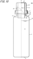
- the liquid container 500 according to the third embodiment of the disclosure illustrated in FIG. 10 has a container body 10, a nozzle 20, an outer tube 30, and a cap 40.
- the definitions of "vertical direction”, “radial direction”, “central axis”, and “integrally molding” are the same as in the first embodiment, so further explanation here is omitted. Components that have the same functions as in the first embodiment will be described with the same reference signs as in the first embodiment.
- a side on which an upper end of the nozzle 20 is located may be described as a tip side.
- a lower end of a measuring tube 47a of the cap 40 may be described as a tip.
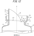
- FIGS. 10 , 12 , and 13 illustrate a state in which an accommodation space S of the container body 10 is filled with content liquid.
- the container body 10 is formed in the shape of a bottle with a body portion 11 that compartmentally forms the accommodation space S for the content liquid inside, a bottom portion 12 that closes a lower end of the body portion 11, and a cylindrical neck portion 15a that is connected to an upper end of the body portion 11 via a shoulder portion 13, so that the content liquid (not illustrated) can be contained in the accommodation space S.
- the container body 10 can be made of synthetic resin, such as polyethylene (PE), polypropylene (PP), polystyrene (PS), or polyethylene terephthalate (PET).
- the nozzle 20 is integrally molded with the container body 10 so as to be connected to an upper end of the neck portion 15a of the container body 10.
- the nozzle 20 is formed in the shape of the letter C in cross section, i.e. the shape of a gutter, with a notch 22 extending from one end to the other end along an axial direction at one circumferential point of a cylindrical tube wall 21.
- a beveled portion 23 that is cut to be rounded when viewed from the side is formed.
- This configuration allows the content liquid contained in the accommodation space S of the container body 10 to be easily poured out at a desired position through the nozzle 20.
- the nozzle 20 protrudes upward from the upper end of the neck portion 15a and is formed of the same synthetic resin material as the container body 10.
- an outer peripheral surface 21c of the tube wall 21 is in the shape of an arc of a regular circle in plan view.
- the tube wall 21 is not in the shape of a perfect regular circle in plan view due to the provision of the notch 22, the tube wall 21 is in the shape of an arc, which is part of a regular circle.
- the outer peripheral surface 21c of the tube wall 21 may have the same diameter from the bottom to the top as illustrated in the example in FIG. 12 , or may have a diameter that is reduced or expanded from the bottom to the top.
- the outer peripheral surface 21c of the tube wall 21 is not necessarily in the shape of an arc of a regular circular.
- a pouring groove that guides the content liquid to a desired position may be provided at part of the inner peripheral surface of the tube wall 21 in a circumferential direction.
- a tip of the nozzle 20 is not limited to the beveled portion 23 that is cut to be rounded when viewed from the side, but can be of various shapes, such as straight inclined beveled portions.
- the outer tube 30 for attaching the cap 40 (see FIG. 13 ) is provided on the radial outside of the nozzle 20, the outer tube 30 for attaching the cap 40 (see FIG. 13 ) is provided.
- the outer tube 30 is integrally molded with the container body 10 so as to be connected to the upper end of the neck portion 15a of the container body 10.
- the outer tube 30 includes a cylindrical peripheral wall (outer peripheral wall) 31, an annular neck ring 32 protruding radially outward at a lower portion of the peripheral wall 31, and a bottom wall 33 inclined radially inward and downward from a lower end of the peripheral wall 31.
- An inner peripheral edge of the bottom wall 33 is connected to the upper end of the neck portion 15a of the container body 10.
- the container body 10, the nozzle 20, and the outer tube 30 (including the peripheral wall 31 and the bottom wall 33) are integrally molded of the same synthetic resin material.
- the area enclosed by the tube wall 21 of the nozzle 20, the peripheral wall 31 of the outer tube 30, and the bottom wall 33 of the outer tube 30 functions as a liquid recovery channel R that returns the content liquid that has leaked to the radial outside of the nozzle 20 into the accommodation space S.
- the bottom wall 33 extending radially inward and downward from the lower end of the peripheral wall 31 of the outer tube 30 functions as a bottom wall 33 of the liquid recovery channel R
- the peripheral wall 31 of the outer tube 30 functions as an outer peripheral wall of the liquid recovery channel R.
- the configuration of the liquid recovery channel R, the notch 22, a connecting passage 35, the peripheral wall 31, and the cap 40 is similar to that of the first embodiment, although there are some portions with slightly different shapes, so a detailed description here is omitted.
- a lower surface of the bottom wall 33 of the liquid recovery channel R is provided approximately in parallel with an upper surface of the bottom wall 33 so as to have a constant thickness.
- the preform 600 can be mounted on a blow molding die without tilting the preform 600, by butting and securing a horizontal plane of the lower surface of the bottom wall 133 against a reference plane of the blow molding die, without the need for precisely aligning the preform 600 with the blow molding die in the circumferential direction.
- the cap 40 includes an outer peripheral wall 41 that covers the nozzle 20 from the radial outside, a top wall 43 that closes an upper end of the outer peripheral wall 41, a flange portion 44 that protrudes radially outward from a lower end of the outer peripheral wall 41, an attachment tube 45 that hangs down from an outer edge of the flange portion 44, a sealing wall 46 that hangs down from a lower surface of the flange portion 44 on the radial inside of the attachment tube 45 and contacts an inner surface of the peripheral wall 31 for sealing in a liquid-tight manner, and a measuring tube 47a that hangs down from the radial inside of the outer peripheral wall 41 in the top wall 43.
- a female thread 45a that is screwed into a male thread 31a formed in the peripheral wall 31 of the outer tube 30 is formed.
- the cap 40 plays the role of preventing the content liquid from leaking out of a nozzle opening 21a, which is compartmentally formed by the nozzle 20, but can also function as a measuring cap by attaching a scale for measuring, indicated by ribbed projections or printing, for example, on the measuring tube 47a.
- the cap 40 can be made of transparent or translucent resin to facilitate measuring the content liquid.
- the content liquid can be poured into the measuring tube 47a and measured with the cap 40 in a posture such that the top wall 43 of the cap 40, which is formed into a flat plate, is on a lower side and the lower end (tip) of the measuring tube 47a is on an upper side.
- the measuring tube 47a in the shape of a cylinder with a top is disposed on the radial inside of the nozzle 20.
- the lower end (tip) of the measuring tube 47a extends downward beyond a lower end of the nozzle 20, enters into the interior of the container body 10.
- the accommodation space S of the body portion 11 of the container body 10 is filled with the content liquid, and the lower end of the measuring tube 47a extends to an area of a headspace HS, which is not filled with the content liquid.
- the headspace HS is a space above a liquid level and below the upper end of the neck portion 15a when the accommodation space S is filled with the maximum amount of the content liquid, as illustrated in FIG. 10 .
- the volume of the headspace HS varies depending on the shape of the liquid container 500, the type of the content liquid, and the like, but is generally on the order of 10% to 40% of the accommodation space S.
- the percentage of the headspace HS to the accommodation space S is not limited to the range described above.
- the measuring tube 47a is configured to be disposed on the radial inside of the nozzle 20.
- a vertical distance RH see FIG. 13
- the lower end of the measuring tube 47a only penetrates deeply into the body portion 11 of the container body 10 and does not interfere with other components. Therefore, the vertical distance RH between the lower end of the measuring tube 47a and the lower end of the attachment tube 45 can be determined in consideration of the ease of use for users, without increasing the overall length of the liquid container 500.
- the vertical distance RH described above is approximately 15.4 millimeters, which is longer than a vertical distance NH (approximately 15.0 millimeters) between an upper end of the peripheral wall 31 and the upper end of the nozzle 20 in FIG. 13 .
- the vertical distance NH between the upper end of the peripheral wall 31 and the upper end of the nozzle 20 is an index length for the ease of pouring and the avoidance of dripping when the content liquid is poured out from the nozzle 20.
- the vertical distance RH between the lower end of the measuring tube 47a and the lower end of the attachment tube 45 can be made longer than the vertical distance NH between the upper end of the peripheral wall 31 and the upper end of the nozzle 20, the ease of pouring and the avoidance of dripping can be improved not only when the content liquid is poured out from the nozzle 20, but also when the content liquid is poured out from the measuring tube 47a of the cap 40.
- the lower end of the measuring tube 47a extends downward beyond the lower end of the nozzle 20, but only to the area (see FIG. 13 ) of the headspace HS, which is not filled with the content liquid. Therefore, it is possible to prevent the content liquid from adhering to the lower end of the measuring tube 47a when the liquid container 500 is stored. Therefore, when the content liquid is measured with the cap 40 in a posture such that the top wall 43 of the cap 40 is on the lower side and the lower end (tip) of the measuring tube 47a is on the upper side, no content liquid is on the tip of the measuring tube 47a, so it is possible to prevent the content liquid from leaking out of the measuring tube 47a.
- a gap G (see FIG. 13 ) between an outer peripheral surface of the measuring tube 47a and an inner peripheral surface of the neck portion 15a is configured to be 1 millimeter or more and 3 millimeters or less.
- the gap G By setting the gap G to 1 millimeter or more, the liquid can be smoothly recovered through the gap G.
- the gap G by setting the gap G to 3 millimeters or less, the width of the liquid recovery channel R and the inner diameter of the measuring tube 47a can be easily secured sufficiently. In other words, when the width of the liquid recovery channel R is not changed, the inner diameter of the measuring tube 47a can be easily secured large enough. When the inner diameter of the measuring tube 47a is not changed, the width of the liquid recovery channel R can be secured large enough.
- the lower end (tip) of the measuring tube 47a is configured to be of approximately the same height over the circumferential direction, but it is not limited to this aspect.
- the lower end of the measuring tube 47a may be configured with a beveled portion, as in the nozzle 20, so that metered content liquid can be easily poured out through the measuring tube 47a to a desired position.
- the radial width of the liquid recovery channel R is configured to be 3 millimeters or more. With this configuration, the content liquid that has leaked out of the nozzle 20 can be recovered into the liquid recovery channel R, without leaking to the outside of the peripheral wall 31.
- the cap 40 is turned around a central axis O to release the screw engagement between the cap 40 and the outer tube 30 so that the cap 40 can be moved upward against the container body 10.
- the cap 40 can then be removed from the outer tube 30 by pulling the cap 40 upward with the screw engagement completely disengaged.
- the container body 10 With the cap 40 removed from the outer tube 30 and the nozzle 20 exposed, the container body 10 is tilted from an upright position with the tip of the nozzle 20 facing upward to an inclined position with the notch 22 facing upward. Thereby, the content liquid in the accommodation space S can be guided into the tube wall 21 through the nozzle opening 21a and poured out.
- the nozzle 20 can be closed by attaching the cap 40 by screwing a female thread 45a of the cap 40 back into a male thread 31a of the outer tube 30.
- a preform 600 illustrated in FIG. 14 is integrally molded by injection molding or the like. Then, a reference plane provided in a neck ring 132 or the like of the preform 600 is butted against a reference plane of a blow molding die so as to secure the preform 600 to the die, and biaxial stretch blow molding is performed.
- the preform 600 includes a main body 110 having the shape of a test tube, and a nozzle 120 and an outer tube 130 that are integrally molded at an upper end of the main body 110.
- the main body 110 includes a cylindrical body portion 111, and an approximately hemispherical bottom portion 112 that closes a lower end of the body portion 111.
- the main body 110 is a portion that forms the neck portion 15a, the shoulder portion 13, the body portion 11, and the bottom portion 12 of the liquid container 500 by biaxial stretch blow molding of the preform 600, and has an interior space S2.
- the nozzle 120 and the outer tube 130 of the preform 600 have the same shapes as the nozzle 20 and the outer tube 30 of the liquid container 500, and are parts that do not deform (expand) during biaxial stretch blow molding.
- the nozzle 120 is formed in the shape of the letter C in cross section, i.e. the shape of a gutter, with a notch 122 extending from one end to the other end along an axial direction at one circumferential point of a cylindrical tube wall 121.
- a beveled portion 123 that is cut to be rounded when viewed from the side is formed at a circumferential edge forming the notch 122 at an upper portion of the tube wall 121.
- the outer tube 130 of the preform 600 includes an approximately cylindrical peripheral wall 131, an annular neck ring 132 protruding radially outward at a lower portion of the peripheral wall 131, and a bottom wall 133 inclined radially inward and downward from a lower end of the peripheral wall 131.
- An inner peripheral edge of the bottom wall 133 is connected to an upper end of the main body 110.
- the area enclosed by the tube wall 121 of the nozzle 120, the peripheral wall 131 of the outer tube 130, and the bottom wall 133 of the outer tube 130 forms the liquid recovery channel R.
- the reference plane such as the neck ring 132 of the preform 600 is butted against and secured to the reference plane of the blow molding die, and a pressurized fluid is supplied to the interior of the preform 600, while the main body 110 is stretched axially by a stretch rod, to perform biaxial stretch blow molding.
- the main body 110 is axially and radially stretched by blow molding to form the liquid container 500 by forming the neck portion 15a, the shoulder portion 13, the body portion 11, and the bottom portion 12 illustrated in FIG. 10 .
- the liquid container 500 in which the container body 10, the nozzle 20, and the outer tube 30 (including the peripheral wall 31 and the bottom wall 33) are integrally molded can be formed by expanding only the main body 110 of the preform 600, in which the main body 110, the nozzle 120, and the outer tube 130 (including the peripheral wall 131 and the bottom wall 133) are integrally molded, by biaxial stretch blow molding. Since the liquid recovery channel R is compartmentally formed by the nozzle 20 and the outer tube 30, the liquid container 500 is a container in which the container body 10, the nozzle 20, and the liquid recovery channel R are integrally molded.
- the present embodiment is the liquid container 500 including the container body 10 that compartmentally forms the accommodation space S for the content liquid, the cylindrical nozzle 20 that is connected to an upper portion of the container body 10 and guides the content liquid to the outside, the liquid recovery channel R that returns the content liquid on the radial outside of the nozzle 20 into the accommodation space S, and the cap 40 that covers the nozzle 20 from above.
- the container body 10, the nozzle 20, and the liquid recovery channel R are formed by integral molding.
- the cap 40 has the measuring tube 47a in the shape of a cylinder with a top. When the cap 40 is attached, the measuring tube 47a is configured to be disposed on the radial inside of the nozzle 20.
- the measuring tube 47a is disposed on the radial inside of the nozzle 20, even if the vertical distance RH (see FIG. 13 ) between the lower end of the measuring tube 47a and the lower end of the attachment tube 45 is lengthened in order to improve the ease of pouring and the avoidance of dripping, there is no interference with other components, such as the liquid recovery channel R. Therefore, it is possible to improve the ease of pouring the content liquid and the avoidance of dripping, by determining the vertical distance RH between the lower end of the measuring tube 47a and the lower end of the attachment tube 45 in consideration of the ease of use for users, without increasing the overall length of the liquid container 500. By increasing the axial length of the measuring tube 47a, the volume of the measuring tube 47a can be secured while maintaining the slim shape without enlarging the liquid container 500 in the radial direction.
- the lower end of the measuring tube 47a when the cap 40 is attached, the lower end of the measuring tube 47a is configured to extend downward beyond the nozzle 20 and be disposed inside the container body 10.
- the vertical length of the measuring tube 47a can be extended beyond the vertical distance between the top wall 43 and the bottom wall 33 of the liquid recovery channel R. Therefore, the ease of pouring the content liquid and the avoidance of dripping can be further improved.
- the container body 10 has the body portion 11 that compartmentally forms the accommodation space S for the content liquid, the bottom portion 12 that closes the lower end of the body portion 11, and the neck portion 15a that is connected to the upper end of the body portion 11 and has a reduced diameter than the body portion 11.
- the radial distance (gap G in FIG. 13 ) between the outer peripheral surface of the measuring tube 47a and the inner peripheral surface of the neck portion 15a is configured to be 1 millimeter or more and 3 millimeters or less.
- the cap 40 further has the attachment tube 45 that is attached to the outer peripheral wall (peripheral wall 31) of the liquid recovery channel R.
- the vertical distance from the lower end of the attachment tube 45 to the lower end of the measuring tube 47a is configured to be greater than the vertical distance from the upper end of the outer peripheral wall of the liquid recovery channel R to the upper end of the nozzle 20.
- the radial width of the liquid recovery channel R is configured to be 3 millimeters or more.
- the liquid container 500 is a liquid container with content liquid contained in the accommodation space S.
- the lower end of the measuring tube 47a is configured to be located, in the container body 10, inside the headspace HS in which no content liquid is contained.
- liquid container 700 according to a fourth embodiment of the disclosure will be exemplarily described in more detail with reference to the drawings.
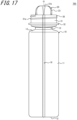
- the liquid container 700 according to the fourth embodiment of the disclosure illustrated in FIG. 15 has a container body 10, a nozzle 20, and an outer tube 30.
- the definitions of "vertical direction”, “radial direction”, “central axis”, and “integrally molding” are the same as in the first embodiment, so further explanation here is omitted. Components that have the same functions as in the first embodiment will be described with the same reference signs as in the first embodiment.
- a side on which the nozzle 20 is located may be described as a tip side.
- the container body 10 is formed in the shape of a bottle with a body portion 11 that compartmentally forms an accommodation space S for content liquid inside, a bottom portion 12 that closes a lower end of the body portion 11, and a cylindrical opening portion 15 that is connected to an upper end of the body portion 11 via a shoulder portion 13, so that the content liquid (not illustrated) can be contained in the accommodation space S.
- the container body 10 includes, at part in a circumferential direction, a window portion 18 through which the content liquid in the accommodation space S is visible.
- the window portion 18 is provided in the shape of a vertical strip extending from an upper end of the outer tube 30 to the bottom portion 12 of the container body 10, as described later.
- the container body 10 has a transparent resin layer TT, which forms the window portion 18, and an opaque resin layer OP, which has light-shielding properties, arranged adjacent to each other in the circumferential direction.
- the container body 10 can be made of synthetic resin, such as polyethylene terephthalate (PET), polyethylene (PE), polypropylene (PP), or polystyrene (PS).
- PET polyethylene terephthalate
- PE polyethylene
- PP polypropylene
- PS polystyrene
- the structure is not limited to a single-layer structure, but can also be laminated with, for example, ethylene vinyl alcohol copolymer (EVOH) resin, nylon resin, or the like with high gas barrier properties.
- EVOH ethylene vinyl alcohol copolymer
- the nozzle 20 is integrally molded with the container body 10 so as to be connected to an upper end of the opening portion 15 of the container body 10.
- the nozzle 20 is formed in the shape of the letter C in cross section, i.e. the shape of a gutter, with a notch 22 extending from one end to the other end along an axial direction at one circumferential point of a cylindrical tube wall 21.
- a beveled portion 23 that is cut to be rounded when viewed from the side is formed.
- the nozzle 20 protrudes upward from the upper end of the opening portion 15 and is formed of the same synthetic resin material as the container body 10.
- the nozzle 20 is made of the opaque resin layer OP (see FIG. 18 ).
- the nozzle 20 is provided with the notch 22 at a circumferential position at which the window portion 18 is provided in the container body 10. That is, the nozzle 20 is not provided with a window portion 18.
- an outer peripheral surface 21c of the tube wall 21 is in the shape of an arc of a regular circle in plan view.
- the tube wall 21 is not in the shape of a perfect regular circle in plan view due to the provision of the notch 22, the tube wall 21 is in the shape of an arc, which is part of a regular circle.
- the outer peripheral surface 21c of the tube wall 21 may have the same diameter from the bottom to the top as illustrated in the example in FIG. 15 , or may have a diameter that is reduced or expanded from the bottom to the top.
- the tube wall 21 may have a shape other than a regular circle, such as an oval shape in plan view.
- a pouring groove 21b that guides the content liquid to the desired position is provided at part of an inner peripheral surface of the tube wall 21 of the nozzle 20 in the circumferential direction.
- the configuration of the pouring groove 21b is similar to that of the second embodiment, so further explanation here is omitted.
- the tip of the nozzle 20 is not limited to the beveled portion 23 that is cut to be rounded when viewed from the side, but can be of various shapes, such as straight inclined beveled portions.
- the outer tube 30 for attaching a cap 40 (see FIG. 19 ) is provided on the radial outside of the nozzle 20, the outer tube 30 for attaching a cap 40 (see FIG. 19 ) is provided.
- the outer tube 30 is integrally molded with the container body 10 so as to be connected to the upper end of the opening portion 15 of the container body 10.
- the outer tube 30 includes an approximately cylindrical peripheral wall 31, an annular neck ring 32 protruding radially outward at a lower portion of the peripheral wall 31, and a bottom wall 33 inclined radially inward and downward from a lower end of the peripheral wall 31.
- An inner peripheral edge of the bottom wall 33 is connected to the upper end of the opening portion 15 of the container body 10.
- the container body 10, the nozzle 20, and the outer tube 30 (including the peripheral wall 31 and the bottom wall 33) are integrally molded of the same synthetic resin material.
- the area enclosed by the tube wall 21 of the nozzle 20, the peripheral wall 31 of the outer tube 30, and the bottom wall 33 of the outer tube 30 functions as a liquid recovery channel R that returns the content liquid that has leaked to the radial outside of the nozzle 20 into the accommodation space S.
- the bottom wall 33 extending radially inward and downward from the lower end of the peripheral wall 31 of the outer tube 30 functions as a bottom wall 33 of the liquid recovery channel R.
- a window portion 18 is formed similarly at a circumferential position at which the window portion 18 is formed in the container body 10.
- the vertical strip-shaped window portion 18 is formed, at a circumferential position at which the notch 22 is provided in the nozzle 20, so as to extend from the bottom portion 12 of the container body 10 to the upper end of the outer tube 30.
- This configuration prevents, in a case in which the liquid container 700 is formed by biaxial stretch blow molding of a preform 800 illustrated in FIG. 20 , for example, the opaque resin layer OP adjacent to a flow of the transparent resin layer TT forming the vertical strip-shaped window portion 18 from mixing with the flow of the transparent resin layer TT during molding of the preform 800, as described below. Therefore, a window portion 118 of the preform 800 is not distorted, thus allowing improvement of the appearance of the liquid container 700 after biaxial stretch blow molding.
- the circumferential position at which the window portion 18 is provided is configured to be completely contained within the circumferential position at which the notch 22 is provided. This configuration can prevent the opaque resin layer OP from mixing with the transparent resin layer TT that constitutes the window portion 18.
- the configuration of the liquid recovery channel R, the notch 22, a connecting passage 35, a thinned portion 33a, and the peripheral wall 31 is similar to that of the first embodiment, except that the window portion 18 is provided in part, so a detailed description here is omitted.
- the configuration of the cap 40 is also similar to that of the first embodiment, so a detailed description here is omitted.
- the cap 40 is formed of transparent resin, but is not limited to this aspect, and may be formed using resin with light-shielding properties by coloring or the like.
- a transparent window may be provided at a circumferential position with a scale in order to facilitate measuring the content liquid.
- the cap 40 is turned around a central axis O to release the screw engagement between the cap 40 and the outer tube 30 so that the cap 40 can be moved upward against the container body 10.
- the cap 40 can then be removed from the outer tube 30 by pulling the cap 40 upward with the screw engagement completely disengaged.
- the container body 10 With the cap 40 removed from the outer tube 30 and the nozzle 20 exposed, the container body 10 can be tilted from an upright position with the tip of the nozzle 20 facing upward to an inclined position with the notch 22 facing upward. This allows the pouring groove 21b to be oriented downward, so the content liquid in the accommodation space S can be guided into the tube wall 21 through a nozzle opening 21a, and then poured out through the pouring groove 21b provided on the tip side of the tube wall 21.
- the pouring groove 21b is configured so that the amount of a radially outward recess increases, as well as a circumferential width increases, as the pouring groove 21b nears the tip side.
- This configuration allows the content liquid that has been guided along the inner peripheral surface of the tube wall 21 to be gradually guided radially outward in the pouring groove 21b, thereby facilitating precisely discharging the content liquid at a desired position. It can also provide good drainage when pouring out the content liquid.
- the nozzle 20 can be closed by attaching the cap 40 by screwing a female thread 45a of the cap 40 back into a male thread 31a of the outer tube 30.
- the preform 800 illustrated in FIG. 20 is integrally molded by injection molding or the like. Then, an outer edge portion 134 of a bottom wall 133 of the liquid recovery channel R is butted against a reference plane of a blow molding die so as to secure the preform 800 to the die, and biaxial stretch blow molding is performed.
- the preform 800 includes a main body 110 having the shape of a test tube, and a nozzle 120 and an outer tube 130 that are integrally molded at an upper end of the main body 110.
- the main body 110 includes a cylindrical body portion 111, and an approximately hemispherical bottom portion 112 that closes a lower end of the body portion 111.
- the main body 110 is a portion that forms the opening portion 15, the shoulder portion 13, the body portion 11, and the bottom portion 12 of the liquid container 700 by biaxial stretch blow molding of the preform 800, and has an interior space S2.
- the main body 110 of the preform 800 as with the container body 10 of the liquid container 700, has a window portion 118 made of transparent resin in part in a circumferential direction.
- the window portion 118 is provided in the shape of a vertical strip extending from an upper end of the outer tube 130 to the bottom portion 112 of the main body 110.
- the main body 110 includes a transparent resin layer TT portion that forms the window portion 118 and an opaque resin layer OP portion that has light-shielding properties.
- the nozzle 120 and the outer tube 130 of the preform 800 have the same shapes as the nozzle 20 and the outer tube 30 of the liquid container 700, and are parts that do not deform (expand) during biaxial stretch blow molding.
- the nozzle 120 is formed in the shape of the letter C in cross section, i.e. the shape of a gutter, with a notch 122 extending from one end to the other end along an axial direction at one circumferential point of the cylindrical tube wall 121.
- a beveled portion 123 that is cut to be rounded when viewed from the side is formed at a circumferential edge forming the notch 122 at an upper portion of the tube wall 121.
- the nozzle 120 is provided with the notch 122 at the circumferential position at which the window portion 118 is provided in the main body 110, and the nozzle 120 is not provided with a window portion 118.
- an outer peripheral surface 121c of the tube wall 121 is in the shape of an arc of a regular circle in plan view.
- the tube wall 121 is not in the shape of a perfect regular circle in plan view due to the provision of the notch 122, the tube wall 121 is in the shape of an arc, which is part of a regular circle.
- the outer peripheral surface 121c of the tube wall 121 is located on a regular circle at all areas in plan view.
- a die part for molding the nozzle 120 and a die part for molding the main body 110 can both include a regular circular shape or an arc shape of a regular circle. Therefore, since matching surfaces of the die parts can be made into the shapes of regular circles, the molding accuracy of each die part can be increased, and eccentricity can be prevented due to increase in the alignment accuracy of the die part for molding the main body 110 with respect to the die part for molding the nozzle 120. Therefore, it is possible to prevent eccentricity of the container body 10 in the liquid container 700.
- a pouring groove 121b that guides the content liquid to a desired position is provided in part of an inner peripheral surface of the tube wall 121 of the nozzle 120 in the circumferential direction.
- the pouring groove 121b is provided at a circumferential position opposite the notch 122 in the inner peripheral surface of the tube wall 121 of the nozzle 120.
- the pouring groove 121b is recessed radially outward from the inner peripheral surface of the tube wall 121 as illustrated in FIG. 20 , and extends to an upper end of the tube wall 121.
- the pouring groove 121b is configured so that the amount of a radially outward recess increases, as well as a circumferential width increases, as the pouring groove 121b nears the upper end (tip).
- This configuration allows the content liquid that has been guided along the inner peripheral surface of the tube wall 21 of the liquid container 700 to be gradually guided radially outward in the pouring groove 21b, thereby facilitating precisely discharging the content liquid at a desired position. It can also provide good drainage when pouring out the content liquid.
- the outer tube 130 of the preform 800 includes an approximately cylindrical peripheral wall 131, an annular neck ring 132 protruding radially outward at a lower portion of the peripheral wall 131, and a bottom wall 133 inclined radially inward and downward from a lower end of the peripheral wall 131.
- An inner peripheral edge of the bottom wall 133 is connected to an upper end of the main body 110.
- a window portion 118 is formed similarly at a circumferential position at which the window portion 118 is provided in the main body 110.
- the vertical strip-shaped window portion 118 is formed, at a circumferential position at which the notch 122 is provided in the nozzle 120, so as to extend from the bottom portion 112 of the main body 110 to the upper end of the outer tube 130.
- This configuration prevents the occurrence of turbulence in a flow of the vertical strip-shaped transparent resin layer TT during the manufacture of the preform 800, thus preventing distortion of the window portion 118 of the preform 800 and improving the appearance of the liquid container 700 after biaxial stretch blow molding.
- a cylindrical molten resin body with a transparent resin forming the window portion 118 and an opaque resin that is adjacent to the transparent resin in a circumferential direction is injected into a cavity from a nozzle portion of an injection molding machine for the preform 800.
- This molten resin body has the transparent resin, which corresponds to the window portion 118 of the preform 800, at one point in the circumferential direction.
- the vertical strip-shaped transparent resin formed within the molten resin body injected into the cavity proceeds through the cavity in a direction from the bottom portion 112 to an opening portion of the preform 800, and forms the window portion 118.
- the preform 800 according to the present embodiment is configured so that the circumferential position at which the notch 122 is provided contains the circumferential position at which the window portion 118 is formed. In other words, at the circumferential position at which the window portion 118 is formed, the nozzle 120 is not present by being cut out by the notch 122. Therefore, when the vertical strip-shaped transparent resin injected from a gate reaches the upper end of the main body 110 in FIG. 20 , the transparent resin does not flow to the side of the nozzle 120, but reaches the upper end of the outer tube 130 through the bottom wall 133 and the peripheral wall 131 of the outer tube 130.
- the transparent resin layer TT forming the window portion 118 does not flow to the side of the nozzle 120 at the upper end of the main body 110, but flows on the side of the outer tube 130 to the upper end.
- the transparent resin layer TT forming the window portion 118 is not divided into two paths at the upper end of the main body 110, the flow of molten resin is stabilized and formed into the shape of a vertical strip without mixing of the opaque resin layer OP adjacent thereto.
- the transparent resin that has reached the upper end of the main body 110 is divided into and flows to the side of the outer tube 130 and the side of the nozzle 120. This tends to cause the opaque resin to mix irregularly with the transparent resin. Also, the transparent resin flowing in the nozzle 120 tends to flow at an angle along the beveled portion 123 (to the tip of the nozzle 120).
- the transparent resin forming the window portion 118 does not flow to the side of the nozzle 120, and the transparent resin layer TT can be formed into the shape of a vertical strip to maintain a good appearance.
- the area enclosed by the tube wall 121 of the nozzle 120, the peripheral wall 131 of the outer tube 130, and the bottom wall 133 of the outer tube 130 forms the liquid recovery channel R.
- a thinned portion 133a that is recessed upward is formed in a lower surface of the bottom wall 133, and an outer edge portion 134 of the bottom wall 133, which is not thinned, extends to approximately the same height in the circumferential direction.
- the outer edge portion 134 of the bottom wall 133 of the preform 800 is butted against and secured to the reference plane of the blow molding die, and a pressurized fluid is supplied to the interior of the preform 800, while the main body 110 is stretched axially by a stretch rod, to perform biaxial stretch blow molding.
- the main body 110 is axially and radially stretched by blow molding to form the liquid container 700 by forming the opening portion 15, the shoulder portion 13, the body portion 11, and the bottom portion 12 illustrated in FIG. 15 .
- the liquid container 700 in which the container body 10, the nozzle 20, and the outer tube 30 (including the peripheral wall 31 and the bottom wall 33) are integrally molded can be formed by expanding only the main body 110 of the preform 800, in which the main body 110, the nozzle 120, and the outer tube 130 (including the peripheral wall 131 and the bottom wall 133) are integrally molded, by biaxial stretch blow molding. Since the liquid recovery channel R is compartmentally formed by the nozzle 20 and the outer tube 30, the liquid container 700 is a container in which the container body 10, the nozzle 20, and the liquid recovery channel R are integrally molded.
- the present embodiment is the liquid container 700 including the container body 10 that compartmentally forms the accommodation space S for the content liquid, the cylindrical nozzle 20 that is connected to an upper portion of the container body 10 and guides the content liquid to the outside, and the liquid recovery channel R that returns the content liquid on the radial outside of the nozzle 20 into the accommodation space S through the notch 22 provided at part of the nozzle 20 in the circumferential direction.
- the container body 10, the nozzle 20, and the liquid recovery channel R are formed by integral molding.
- the container body 10 and the liquid recovery channel R are configured to include, at part in the circumferential direction, the vertical strip-shaped window portion 18 through which the content liquid in the accommodation space S is visible.
- the circumferential position at which the notch 22 is provided is configured to contain the circumferential position at which the window portion 18 is provided.
- the present embodiment is configured with the vertical strip-shaped window portion 18 through which the content liquid in the accommodation space S of the container body 10 is visible, users can easily check the amount of the content liquid remaining in the accommodation space S through the window portion 18.
- the opaque resin adjacent to the vertical strip-shaped transparent resin is less likely to be irregularly mixed with the transparent resin during the manufacture of the preform 800 for blow molding the liquid container 700, so the window portion 118 of the preform 800 is not distorted, thus allowing improvement of the appearance of the liquid container 700 after biaxial stretch blow molding.
- the notch 22 provided in the nozzle 20 is configured to constitute the connecting passage 35 that connects the liquid recovery channel R with the accommodation space S, but is not limited to this aspect.
- the tube wall 21 of the nozzle 20 or the liquid recovery channel R may be configured with a connecting hole that connects the liquid recovery channel R with the accommodation space S.
- the bottom wall 33 of the liquid recovery channel R is configured to be provided with the thinned portion 33a that is recessed upward from the lower surface on the radial inside of the bottom wall 33, but is not limited to this aspect.
- the bottom wall 33 may be provided with no thinned portion 33a, or the thinned portion 33a on the radial outside or radial middle of the bottom wall 33.
- the pouring groove 21b is configured so that the amount of the radially outward recess increases, as well as the circumferential width increases, as the pouring groove 21b nears the upper end, but is not limited to this aspect.
- the circumferential width and the amount of the radially outward recess of the pouring groove 21b can be set arbitrarily, as long as the pouring groove 21b is a groove provided at part of the inner peripheral surface of the tube wall 21 of the nozzle 20 in the circumferential direction.
- the lower end of the measuring tube 47a is configured to extend downward beyond the nozzle 20 and into the headspace HS in the container body 10, but is not limited to this aspect.
- the lower end of the measuring tube 47a may be positioned above the lower end of the nozzle 20 or may be immersed in the content liquid beyond the headspace HS.
- the vertical distance RH from the lower end of the attachment tube 45 to the lower end of the measuring tube 47a is configured to be greater than the vertical distance NH from the upper end of the outer peripheral wall of the liquid recovery channel R to the upper end of the nozzle 20, but is not limited to this aspect.
- the vertical distance RH may be less than or equal to the vertical distance NH.
- the window portion 18 has the single-layer structure constituted of the transparent resin layer TT, but is not limited to this aspect.
- the window portion 18 may have a laminated structure with other functional layers.
- the window portion 18 does not necessarily need to be composed of a completely transparent resin layer, but may be composed of a translucent resin layer, as long as the window portion 18 has enough transparency and visible light transmittance to allow viewing of the remaining amount of the content liquid.
- the area excluding the window portion 18 is configured to have the single-layer structure constituted of the opaque resin layer OP, but is not limited to this aspect.
- the area excluding the window portion 18 may have a laminated structure of two or more layers. In the case of a laminated structure, at least one layer is preferably made of opaque resin to ensure light-shielding properties.
Landscapes
- Engineering & Computer Science (AREA)
- Mechanical Engineering (AREA)
- Ceramic Engineering (AREA)
- Physics & Mathematics (AREA)
- Geometry (AREA)
- Manufacturing & Machinery (AREA)
- Closures For Containers (AREA)
Abstract
Description
- This application claims priority to
Japanese Patent Application No. 2021-125840 filed on July 30, 2021 Japanese Patent Application No. 2021-178247 filed on October 29, 2021 Japanese Patent Application No. 2022-12391 filed on January 28, 2022 Japanese Patent Application No. 2022-30499 filed on February 28, 2022 - This disclosure relates to a liquid container including a container body and a nozzle, and a liquid container with content liquid.
- Conventionally, as containers that contain content liquid with relatively high viscosity, such as liquid laundry detergent or fabric softener, liquid containers that include a nozzle at an opening of a container body with an accommodation space for content liquid and a nozzle cap attached thereto are known (see, for example, Patent Literature (PTL) 1).
- In such liquid containers, the nozzle is generally formed in the shape of a gutter, supported by a bulkhead of the nozzle cap, and disposed so that its tip protrudes outward from a tip opening of the nozzle cap. This allows the content liquid to be easily poured out through the nozzle to a targeted position.
- PTL 1:
Japanese Patent No. 5094620 - However, there is room for improvement in the above conventional liquid containers in that the nozzle cap, which is a separate component, is attached to the container body that contains the content liquid, which makes sorting and disposal complicated.
- The disclosure aims to solve such a problem. It would be helpful to provide a liquid container and a liquid container with content liquid that are easy to sort and dispose of, while preventing dripping of the liquid from a nozzle to the outside.
- To solve the above problem, a liquid container according to the disclosure is
- [1]
a liquid container including:- a container body configured to compartmentally form an accommodation space for content liquid;
- a tubular nozzle configured to be connected to an upper portion of the container body and guide the content liquid to the outside; and
- a liquid recovery channel configured to return the content liquid on the radial outside of the nozzle into the accommodation space,
- wherein the container body, the nozzle, and the liquid recovery channel are formed by integral molding.
- [2]
in the configuration described in above [1], the liquid recovery channel is preferably inclined downward toward a circumferential direction, and a connecting passage that connects the liquid recovery channel with the accommodation space is preferably provided at a lower end of the liquid recovery channel.
According to the liquid container of the disclosure, - [3]
in the configuration described in above [1] or [2], a bottom wall of the liquid recovery channel preferably has a thinned portion that is recessed upward from a lower surface of the bottom wall, and the thickness of the bottom wall at an area with the thinned portion is preferably substantially constant in a direction along the liquid recovery channel.
According to the liquid container of the disclosure, - [4]
in the configuration described in any of above [1] to [3], a bottom wall of the liquid recovery channel preferably has a thinned portion that is recessed upward from a lower surface of the bottom wall, and an area excluding the thinned portion in the lower surface of the bottom wall preferably extends horizontally over a circumferential direction.
According to the liquid container of the disclosure, - [5]
in the configuration described in any of above [1] to [4], an upper surface of a bottom wall of the liquid recovery channel is preferably inclined downward from the radial outside to the radial inside.
According to the liquid container of the disclosure, - [6]
in the configuration described in any of above [1] to [5], an outer tube is preferably formed on the radial outside of the nozzle, and the liquid recovery channel is preferably formed at a radial position between the nozzle and the outer tube.
According to the liquid container of the disclosure, - [7]
- in the configuration described in above [1],
- a pouring groove that is recessed radially outward and extends to an upper end of a tube wall of the nozzle is preferably provided at part of an inner peripheral surface of the tube wall of the nozzle in the circumferential direction, and
- an outer peripheral surface of the tube wall of the nozzle is preferably located on a regular circle in plan view.
- [8]
in the configuration described in above [7], the amount of a radially outward recess of the pouring groove preferably increases, as well as the circumferential width of the pouring groove preferably increases, as the pouring groove nears the upper end.
According to the liquid container of the disclosure, - [9]
- in the configuration described in above [1], the liquid container further includes a cap configured to cover the nozzle from above,
- wherein
- the cap preferably has a measuring tube in the shape of a cylinder with a top, and
- when the cap is attached, the measuring tube is preferably disposed on the radial inside of the nozzle.
- [10]
in the configuration described in above [9], when the cap is attached, a lower end of the measuring tube preferably extends downward beyond the nozzle and is preferably disposed inside the container body.
According to the liquid container of the disclosure, - [11]
- in the configuration described in above [9] or [10],
- the container body preferably includes a body portion configured to compartmentally form the accommodation space for the content liquid, a bottom portion configured to close a lower end of the body portion, and a neck portion configured to be connected to an upper end of the body portion and have a reduced diameter than the body portion, and
- the radial distance between an outer peripheral surface of the measuring tube and an inner peripheral surface of the neck portion is preferably 1 millimeter or more and 3 millimeters or less.
- [12]
in the configuration described in any of above [9] to [11], the cap preferably further includes an attachment tube configured to be attached to an outer peripheral wall of the liquid recovery channel, and the vertical distance from a lower end of the attachment tube to a lower end of the measuring tube is preferably greater than the vertical distance from an upper end of the outer peripheral wall of the liquid recovery channel to an upper end of the nozzle.
According to the liquid container of the disclosure, - [13]
in the configuration described in any of above [9] or [12], the radial width of the liquid recovery channel is preferably 3 millimeters or more.
A liquid container with content liquid according to the disclosure is - [14]
- a liquid container with content liquid including content liquid contained in the accommodation space in the liquid container described in above [10],
- wherein when the cap is attached, the lower end of the measuring tube is located, in the container body, inside a headspace in which no content liquid is contained.
- [15]
- in the configuration described in above [1], the liquid recovery channel is preferably configured to return the content liquid on the radial outside of the nozzle into the accommodation space through a notch provided at part of the nozzle in a circumferential direction,
- the container body and the liquid recovery channel preferably have, at part in the circumferential direction, a vertical strip-shaped window portion through which the content liquid in the accommodation space is visible, and
- a circumferential position at which the notch is provided preferably contains a circumferential position at which the window portion is provided.
- According to the disclosure, it is possible to provide a liquid container and a liquid container with content liquid that are easy to sort and dispose of, while preventing dripping of the liquid from a nozzle to the outside.
- In the accompanying drawings:
-
FIG. 1 is a front half cross-sectional view of a liquid container according to a first embodiment of the disclosure; -
FIG. 2 is a plan view of the liquid container according to the first embodiment of the disclosure; -
FIG. 3 is a cross-sectional view along the section A-A ofFIG. 2 ; -
FIG. 4 is an enlarged front cross-sectional view illustrating a state in which a nozzle ofFIG. 3 is covered with a cap; -
FIG. 5 is a front half cross-sectional view of a preform used in the manufacture of the liquid container according to the first embodiment of the disclosure; -
FIG. 6 is a plan view of a liquid container according to a second embodiment of the disclosure; -
FIG. 7 is a cross-sectional view along the section B-B ofFIG. 6 ; -
FIG. 8 is an enlarged front cross-sectional view illustrating a state in which a nozzle ofFIG. 7 is covered with a cap; -
FIG. 9 is a front half cross-sectional view of a preform used in the manufacture of the liquid container according to the second embodiment of the disclosure; -
FIG. 10 is a front half cross-sectional view of a liquid container with content liquid according to a third embodiment of the disclosure; -
FIG. 11 is a plan view of a container body, a nozzle, and a liquid recovery channel that constitute the liquid container according to the third embodiment of the disclosure; -
FIG. 12 is a cross-sectional view along the section C-C ofFIG. 11 ; -
FIG. 13 is an enlarged front cross-sectional view of the nozzle, the liquid recovery channel, and a cap inFIG. 10 ; -
FIG. 14 is a front half cross-sectional view of a preform used in the manufacture of the liquid container according to the third embodiment of the disclosure; -
FIG. 15 is a front cross-sectional view of a liquid container according to a fourth embodiment of the disclosure; -
FIG. 16A is a plan view of the liquid container according to the fourth embodiment of the disclosure; -
FIG. 16B is a cross-sectional view along the section D-D ofFIG. 15 ; -
FIG. 17 is a side view of a liquid container according to a fourth embodiment of the disclosure; -
FIG. 18 is a cross-sectional view along the section E-E ofFIG. 16A ; -
FIG. 19 is an enlarged front cross-sectional view illustrating a state in which a nozzle ofFIG. 18 is covered with a cap; and -
FIG. 20 is a front cross-sectional view of a preform used in the manufacture of the liquid container according to the fourth embodiment of the disclosure. - The disclosure will be exemplarily described below in more detail with reference to the drawings.
- A
liquid container 100 according to a first embodiment of the disclosure illustrated inFIG. 1 is suitable for containing content liquid with relatively high viscosity, such as, for example, liquid laundry detergent or fabric softener, and has acontainer body 10, anozzle 20, and anouter tube 30. In this specification, claims, abstract, and drawings, the side on which thenozzle 20 is located is referred to as an upper side (upper side inFIG. 1 ), and the side on which abottom portion 12 of thecontainer body 10 is located is referred to as a lower side (lower side inFIG. 1 ). A radial outside is referred to as a direction away from the central axis O of theliquid container 100 extending in a vertical direction inFIG. 1 , along a straight line that passes the central axis O and is perpendicular to the central axis O. A radial inside is referred to as a direction toward the central axis O along the straight line. The central axis O inFIG. 1 is used to define the radial outside and the radial inside, and does not mean that every component of theliquid container 100 in the present embodiment is always formed axisymmetrically around this central axis O. - In this specification, claims, abstract, and drawings, "integral molding" means one molded as a single piece with a die, including one molded as a single piece by insert molding, two-color molding, or the like, but does not include one that is made by integrating separate members molded with separate dies in a subsequent process that does not involve resin molding such as adhesion.
- The
container body 10 is formed in the shape of a bottle with abody portion 11 that compartmentally forms an accommodation space S for the content liquid inside, thebottom portion 12 that closes a lower end of thebody portion 11, and acylindrical opening portion 15 that is connected to an upper end of thebody portion 11 via ashoulder portion 13, so that the content liquid (not illustrated) can be contained in the accommodation space S. Thecontainer body 10 can be made of synthetic resin, such as polyethylene (PE), polypropylene (PP), polystyrene (PS), or polyethylene terephthalate (PET). The openingportion 15 is not limited to a cylindrical shape, but can be formed in other shapes as long as the openingportion 15 is tubular, such as an oval tubular or square tubular. - As illustrated in
FIGS. 1 and3 , thenozzle 20 is integrally molded with thecontainer body 10 so as to be connected to an upper end of the openingportion 15 of thecontainer body 10. In the present embodiment, thenozzle 20 is formed in the shape of the letter C in cross section, i.e. the shape of a gutter, with anotch 22 extending from one end to the other end along an axial direction at one circumferential point of an approximatelycylindrical tube wall 21, and abeveled portion 23 is formed at a circumferential edge forming thenotch 22 at an upper portion of thetube wall 21. This configuration allows the content liquid contained in the accommodation space S of thecontainer body 10 to be easily poured out at a desired position through thenozzle 20. Thenozzle 20 protrudes upward from the upper end of the openingportion 15 and is formed of the same synthetic resin material as thecontainer body 10. - A tip of the
nozzle 20 is not limited to the shape with the inclinedbeveled portion 23, but can be of various shapes, such as a shape cut to be rounded when viewed from the side. - An
outer tube 30 to attach acap 40 is provided on the radial outside of the nozzle 20 (seeFIG. 4 ). As with thenozzle 20, theouter tube 30 is integrally molded with thecontainer body 10 so as to be connected to the upper end of the openingportion 15 of thecontainer body 10. Theouter tube 30 includes an approximately cylindricalperipheral wall 31, anannular neck ring 32 protruding radially outward at a lower portion of theperipheral wall 31, and abottom wall 33 inclined radially inward and downward from a lower end of theperipheral wall 31. An inner peripheral edge of thebottom wall 33 is connected to the upper end of the openingportion 15 of thecontainer body 10. In the present embodiment, thecontainer body 10, thenozzle 20, and theouter tube 30 are integrally molded of the same synthetic resin material. - In the present embodiment, the area enclosed by the
tube wall 21 of thenozzle 20, theperipheral wall 31 of theouter tube 30, and thebottom wall 33 of theouter tube 30 functions as a liquid recovery channel R that returns the content liquid that has leaked to the radial outside of thenozzle 20 into the accommodation space S. In other words, thebottom wall 33 extending radially inward and downward from the lower end of theperipheral wall 31 of theouter tube 30 functions as abottom wall 33 of the liquid recovery channel R. - An upper surface of the
bottom wall 33 of the liquid recovery channel R is formed, inFIGS. 2 and3 , so that a left end is the highest and a right end, at which thenotch 22 is provided, is the lowest. In other words, thebottom wall 33 is inclined downward from the left end to the right end so as to be gradually lower along the channel. InFIG. 2 , the liquid recovery channel R has two paths, one from the left end to the right end clockwise along the channel and the other from the left end to the right end counterclockwise along the channel. In either path, the upper surface of thebottom wall 33 is inclined so as to be gradually lower from the left end to the right end. In other words, the upper surface of thebottom wall 33 of the liquid recovery channel R is formed spirally over a half-circumference from the left end to the right end. Thebottom wall 33 is inclined downward from the radial outside to the radial inside at the same circumferential position. The upper surface of thebottom wall 33 gradually lowering from the left end to the right end inFIGS. 2 and3 means that the upper surface of thebottom wall 33 gradually lowers from the left end to the right end at the same radial position (same widthwise position of the channel). - In the present embodiment, a lower end of the
notch 22 provided at one circumferential point of thenozzle 20 constitutes a connectingpassage 35 that connects the liquid recovery channel R with the accommodation space S. The content liquid that has leaked to the radial outside of thenozzle 20 enters the liquid recovery channel R and moves to a low direction from the left end to the right end of thebottom wall 33 inFIGS. 2 and3 . The content liquid that has moved within the liquid recovery channel R to the right end of thebottom wall 33 moves further radially inward, and is returned through the connecting passage 35 (seeFIGS. 2 and3 ) to the accommodation space S of thecontainer body 10. - In the present embodiment, as illustrated in
FIG. 3 and the like, thebottom wall 33 of the liquid recovery channel R is made thinner at an area excluding anouter edge portion 34 by providing a thinnedportion 33a that is recessed upward from a lower surface of thebottom wall 33. The wall thickness of thebottom wall 33 at the area that is made thinner by wall-thinning is approximately constant in a direction along the channel. The thickness of thebottom wall 33 at the area that is made thinner by wall-thinning is also approximately constant in a radial direction. In other words, the thinned area in thebottom wall 33 of the liquid recovery channel R is, at the lower surface, as well as at the upper surface through which the content liquid flows, inclined downward from the left end to the right end ofFIGS. 2 and3 and downward radially inward. - As described above, by providing the thinned
portion 33a in thebottom wall 33 of the liquid recovery channel R so that the thickness is configured to be made uniform at the thinned area especially in a circumferential direction, when a preform 200 (seeFIG. 5 ) described below is integrally molded to manufacture theliquid container 100, a molten resin can easily flow evenly around an area corresponding to thebottom wall 133 in a die, which prevents the occurrence of a molding defect such as a sink mark. Note that, a configuration without providing the thinnedportion 33a may be adopted. In the case of not providing the thinnedportion 33a, for example, the lower surface of thebottom wall 33 may be configured to be tapered with approximately the same height in the circumferential direction, so that the thickness of thebottom wall 33 gradually becomes thinner in the circumferential direction. - In the present embodiment, a lower surface of the
outer edge portion 34 of thebottom wall 33, which is not provided with the thinnedportion 33a, is configured to extend approximately horizontally over the circumferential direction. In other words, the lower surface of theouter edge portion 34 is formed to be of almost the same height regardless of circumferential position. This configuration allows, for example, when forming theliquid container 100 by biaxial stretch blow molding of thepreform 200 as described below, to mount thepreform 200 on a blow molding die without tilting thepreform 200, by butting and securing a lower end of theouter edge portion 34 of thebottom wall 33 against a reference plane of the blow molding die, without the need for precisely aligning thepreform 200 with the blow molding die in the circumferential direction. - Instead of the
outer edge portion 34 of thebottom wall 33, an upper or lower surface of theneck ring 32 may be butted against the reference plane of the blow molding die to secure thepreform 200. - In the present embodiment, the
bottom wall 33 is configured to be thinned at the area excluding theouter edge portion 34 and to be butted at theouter edge portion 34 against the reference plane of the blow molding die, but is not limited to this aspect. For example, thebottom wall 33 may be configured to be thinned at an area excluding an inner edge portion and to be butted at the inner edge portion against the reference plane of the die. - An outer peripheral surface of an upper portion of the
peripheral wall 31 of theouter tube 30 is provided with amale thread 31a for attaching thecap 40 described below by screw engagement. Instead of themale thread 31a, an annular protrusion may be provided on theperipheral wall 31 for attaching thecap 40 by stopper engagement. - As illustrated in
FIG. 4 , thecap 40 includes an outerperipheral wall 41 that covers thenozzle 20 from the radial outside, atop wall 43 that closes an upper end of the outerperipheral wall 41, aflange portion 44 that protrudes radially outward from a lower end of the outerperipheral wall 41, anattachment tube 45 that hangs down from an outer edge of theflange portion 44, a sealingwall 46 that hangs down from a lower surface of theflange portion 44 on the radial inside of theattachment tube 45 and contacts an inner surface of theperipheral wall 31 for sealing in a liquid-tight manner, and aninner tube 47 that hangs down from the lower surface of theflange portion 44 on the radial inside of the sealingwall 46. - In an inner surface of the
attachment tube 45, afemale thread 45a that is screwed into themale thread 31a formed in theperipheral wall 31 of theouter tube 30 is formed. As illustrated inFIG. 4 , by screwing thefemale thread 45a of thecap 40 into themale thread 31a of theouter tube 30, making a sealingprotrusion 44a on the lower surface of theflange portion 44 in contact with an upper end surface of theperipheral wall 31, and making the sealingwall 46 in contact with the inner surface of theperipheral wall 31, a liquid-tight seal can be provided against the outside. - In the present embodiment, the
cap 40 plays the role of preventing the content liquid from leaking out of anozzle opening 21a, which is compartmentally formed by thenozzle 20. Thecap 40 can also function as a measuring cap by attaching a scale for measuring, indicated by ribbed projections or printing, for example, on the outerperipheral wall 41. When thecap 40 is used as a measuring cap, for example, thecap 40 can be made of transparent or translucent resin to facilitate measuring the content liquid. - When the
cap 40 is also used as a measuring cap, the liquid can be measured by using thecap 40 in a posture such that thetop wall 43 of thecap 40, which is formed into a flat plate, is on a lower side and an opening of thecap 40 is on an upper side. - From a state illustrated in
FIG. 4 in which thenozzle 20 is covered with thecap 40, thecap 40 is turned around the central axis O to release the screw engagement between thecap 40 and theouter tube 30 so that thecap 40 can be moved upward against thecontainer body 10. Thecap 40 can then be removed from theouter tube 30 by pulling thecap 40 upward with the screw engagement completely disengaged. - With the
cap 40 removed from theouter tube 30 and thenozzle 20 exposed, thecontainer body 10 can be tilted from an upright position with the tip of thenozzle 20 facing upward to an inclined position with thenotch 22 facing upward, in order to pour the content liquid out of the accommodation space S through thenozzle opening 21a from the tip of thenozzle 20. At this time, the content liquid in the accommodation space S of thecontainer body 10 is guided along thenozzle 20, which is formed in the shape of a gutter, and is poured out from the tip of thenozzle 20. When thecontainer body 10 is returned to the upright position after pouring out the content liquid, even if the content liquid adhering to the tip of thenozzle 20 drips down along an outer peripheral surface of thenozzle 20, the content liquid does not drip down to the outside of theouter tube 30, but drips downward along thenozzle 20 and is received by thebottom wall 33 of the liquid recovery channel R. The content liquid that has dripped down into the liquid recovery channel R moves along the inclination of the upper surface of thebottom wall 33 and is returned to the accommodation space S of thecontainer body 10 via the connectingpassage 35. Therefore, thisliquid container 100 can prevent dripping of the content liquid to the outside, while pouring out the content liquid from thenozzle 20. - After use, the
nozzle 20 can be closed by attaching thecap 40 by screwing thefemale thread 45a of thecap 40 back into themale thread 31a of theouter tube 30. - To form the
liquid container 100 according to the present embodiment, for example, thepreform 200 illustrated inFIG. 5 is integrally molded by injection molding or the like. Then, anouter edge portion 134 of abottom wall 133 of the liquid recovery channel R is butted against the reference plane of the blow molding die so as to secure thepreform 200 to the die, and biaxial stretch blow molding is performed. - The
preform 200 includes amain body 110 having the shape of a test tube, and anozzle 120 and anouter tube 130 that are integrally molded at an upper end of themain body 110. Themain body 110 includes acylindrical body portion 111, and an approximatelyhemispherical bottom portion 112 that closes a lower end of thebody portion 111. Themain body 110 is a portion that forms the openingportion 15, theshoulder portion 13, thebody portion 11, and thebottom portion 12 of theliquid container 100 by biaxial stretch blow molding of thepreform 200, and has an interior space S2. - The
nozzle 120 and theouter tube 130 of thepreform 200 have the same shapes as thenozzle 20 and theouter tube 30 of theliquid container 100, and are parts that do not expand during biaxial stretch blow molding. As illustrated inFIG. 5 , thenozzle 120 is formed in the shape of the letter C in cross section, i.e. the shape of a gutter, with anotch 122 extending from one end to the other end along an axial direction at one circumferential point of an approximatelycylindrical tube wall 121, and abeveled portion 123 is formed at a circumferential edge forming thenotch 122 at an upper portion of thetube wall 121. - The
outer tube 130 of thepreform 200 includes an approximately cylindricalperipheral wall 131, anannular neck ring 132 protruding radially outward at a lower portion of theperipheral wall 131, and abottom wall 133 inclined radially inward and downward from a lower end of theperipheral wall 131. An inner peripheral edge of thebottom wall 133 is connected to an upper end of themain body 110. - In the present embodiment, the area enclosed by the
tube wall 121 of thenozzle 120, theperipheral wall 131 of theouter tube 130, and thebottom wall 133 of theouter tube 130 forms the liquid recovery channel R. A thinnedportion 133a that is recessed upward is formed in a lower surface of thebottom wall 133, and anouter edge portion 134 of thebottom wall 133, which is not thinned, extends to approximately the same height in a circumferential direction. - When forming the
liquid container 100 using thepreform 200 illustrated inFIG. 5 , theouter edge portion 134 of thebottom wall 133 of thepreform 200 is butted against and secured to the reference plane of the blow molding die, and a pressurized fluid is supplied to the interior of thepreform 200, while themain body 110 is stretched axially by a stretch rod, to perform biaxial stretch blow molding. In the present embodiment, only themain body 110 is axially and radially stretched by blow molding to form theliquid container 100 by forming the openingportion 15, theshoulder portion 13, thebody portion 11, and thebottom portion 12 illustrated inFIG. 1 . In this method of manufacturing theliquid container 100, theliquid container 100 in which thecontainer body 10, thenozzle 20, and theouter tube 30 are integrally molded can be formed by expanding only themain body 110 of thepreform 200, in which themain body 110, thenozzle 120, and theouter tube 130 are integrally molded, by biaxial stretch blow molding. Since the liquid recovery channel R is compartmentally formed by thenozzle 20 and theouter tube 30, theliquid container 100 is a container in which thecontainer body 10, thenozzle 20, and the liquid recovery channel R are integrally molded. - As described above, in the present embodiment, the
container body 10 that compartmentally forms the accommodation space S for the content liquid, thecylindrical nozzle 20 that is connected to an upper portion of thecontainer body 10 and guides the content liquid to the outside, and the liquid recovery channel R that returns the content liquid on the radial outside of thenozzle 20 into the accommodation space S are configured to be formed by integral molding. By adopting such a configuration, it is possible to effectively prevent dripping of the content liquid to the outside, while pouring out the content liquid from thenozzle 20. In addition, since thecontainer body 10, thenozzle 20, and the liquid recovery channel R are integrally molded, the amount of resin used can be reduced, and since there is no need to separate the nozzle cap from the container body, sort and disposal become easier. - In the present embodiment, the liquid recovery channel R is configured to be inclined downward toward the circumferential direction, and the connecting
passage 35 that connects the liquid recovery channel R with the accommodation space S is configured to be provided at the lower end of the liquid recovery channel R. By adopting such a configuration, the content liquid that has leaked out of thenozzle 20 can be efficiently returned into the accommodation space S by using the inclined surface of the liquid recovery channel R. - In the present embodiment, the
bottom wall 33 of the liquid recovery channel R is configured to have the thinnedportion 33a that is recessed upward from the lower surface of thebottom wall 33, and the thickness of thebottom wall 33 at the area with the thinned portion is configured to be approximately constant in the direction along the channel. By adopting such a configuration, when thepreform 200 for manufacturing theliquid container 100 is integrally molded, the molten resin can easily flow evenly around the area corresponding to thebottom wall 133 in the die, thereby preventing the occurrence of a molding defect such as a sink mark. - In the present embodiment, the
bottom wall 33 of the liquid recovery channel R is configured to have the thinnedportion 33a that is recessed upward from the lower surface of thebottom wall 33, and the area excluding the thinnedportion 33a in the lower surface of thebottom wall 33 is configured to extend horizontally over the circumferential direction. By adopting such a configuration, thepreform 200 can be mounted on the blow molding die without tilting thepreform 200, by butting and securing the area excluding the thinnedportion 33a of thebottom wall 33 against the reference plane of the blow molding die, without the need for precisely aligning thepreform 200 with the blow molding die in the circumferential direction. - In the present embodiment, the upper surface of the
bottom wall 33 of the liquid recovery channel R is configured to be inclined downward from the radial outside to the radial inside. By adopting such a configuration, the content liquid in the liquid recovery channel R can be collected to the radial inside, and the content liquid can be easily returned into the accommodation space S using thenotch 22 of thenozzle 20, as the connectingpassage 35. - In the present embodiment, the
outer tube 30 is configured to be formed on the radial outside of thenozzle 20, and the liquid recovery channel R is configured to be formed at a radial position between thenozzle 20 and theouter tube 30. By adopting such a configuration, since a space between theouter tube 30, to which thecap 40 is attached to prevent leakage of the content liquid, and thenozzle 20 can be used as the liquid recovery channel R, it is possible to prevent leakage of the liquid from theliquid container 100 while maintaining a compact configuration. - Next, a
liquid container 300 according to a second embodiment of the disclosure will be exemplarily described in more detail with reference to the drawings. - The
liquid container 300 according to the second embodiment of the disclosure illustrated inFIGS. 6 and7 has acontainer body 10, anozzle 20, and anouter tube 30. The definitions of "vertical direction", "radial direction", "central axis", and "integrally molding" are the same as in the first embodiment, so further explanation here is omitted. In a description of an inclined posture of theliquid container 300, a side on which an upper end of thenozzle 20 is located may be described as a tip side. Since the configuration of thecontainer body 10 is the same as in the first embodiment, an illustration of an entire diagram of theliquid container 300, including abottom portion 12 of thecontainer body 10, is omitted. Components that have the same functions as in the first embodiment will be described with the same reference signs as in the first embodiment. - As illustrated in
FIG. 7 , thenozzle 20 is integrally molded with thecontainer body 10 so as to be connected to an upper end of anopening portion 15 of thecontainer body 10. In the present embodiment, thenozzle 20 is formed in the shape of the letter C in cross section, i.e. the shape of a gutter, with anotch 22 extending from one end to the other end along an axial direction at one circumferential point of acylindrical tube wall 21. At a circumferential edge forming thenotch 22 at an upper portion of thetube wall 21, abeveled portion 23 that is cut to be rounded when viewed from the side is formed. This configuration allows content liquid contained in an accommodation space S of thecontainer body 10 to be easily poured out at a desired position through thenozzle 20. Thenozzle 20 protrudes upward from the upper end of the openingportion 15 and is formed of the same synthetic resin material as thecontainer body 10. - In the present embodiment, as illustrated in
FIG. 6 , an outerperipheral surface 21c of thetube wall 21 is in the shape of an arc of a regular circle in plan view. In other words, although thetube wall 21 is not in the shape of a perfect regular circle in plan view due to the provision of thenotch 22, thetube wall 21 is in the shape of an arc, which is part of a regular circle. The outerperipheral surface 21c of thetube wall 21 may constitute a complete regular circle in plan view without thenotch 22. The outerperipheral surface 21c of thetube wall 21 may have the same diameter from the bottom to the top as illustrated in the example inFIG. 7 , or may have a diameter that is reduced or expanded from the bottom to the top. With the above configuration, the outerperipheral surface 21c of thetube wall 21 is located on a regular circle at all areas in plan view. The outerperipheral surface 21c of thetube wall 21 refers to an outer surface that extends in a circumferential direction in thetube wall 21. InFIG. 6 , radially extending surfaces that are formed by the provision of thenotch 22 are not included in the outerperipheral surface 21c of thetube wall 21. - Conventional nozzles are configured so that the tip of the nozzle protrudes radially outward, allowing content liquid to be discharged at a desired position through the protruding portion. In the present embodiment, since the outer
peripheral surface 21c of thenozzle 20 is configured to be located on a regular circle in plan view in order to increase the accuracy of theliquid container 300, so the conventional configuration cannot be adopted. Therefore, in order to discharge the content liquid from thenozzle 20 to a desired position, a pouringgroove 21b that guides the content liquid to the desired position is provided at part of an inner peripheral surface of thetube wall 21 of thenozzle 20 in the circumferential direction. - As illustrated in
FIGS. 6 and7 , the pouringgroove 21b according to the present embodiment is provided at a circumferential position opposite thenotch 22 in the inner peripheral surface of thetube wall 21 of thenozzle 20. The pouringgroove 21b is recessed radially outward from the inner peripheral surface of thetube wall 21 as illustrated inFIGS. 6 and7 , and extends to an upper end (tip) of thetube wall 21 as illustrated inFIG. 7 . In the present embodiment, the pouringgroove 21b is configured so that the amount of a radially outward recess increases, as well as a circumferential width increases, as the pouringgroove 21b nears the upper end. In other words, the pouringgroove 21b is in the shape of an inverted triangular pyramid in which circumferential and radial widths increase as the pouringgroove 21b nears the upper end. This configuration allows the content liquid that has been guided along the inner peripheral surface of thetube wall 21 to be gradually guided radially outward in the pouringgroove 21b, thereby facilitating precisely discharging the liquid at the desired position. It can also provide good drainage when pouring out the content liquid. - The tip of the
nozzle 20 is not limited to thebeveled portion 23 that is cut to be rounded when viewed from the side, but can be of various shapes, such as straight inclined beveled portions. - On the radial outside of the
nozzle 20, theouter tube 30 for attaching a cap 40 (seeFIG. 8 ) is provided. As with thenozzle 20, theouter tube 30 is integrally molded with thecontainer body 10 so as to be connected to the upper end of the openingportion 15 of thecontainer body 10. Theouter tube 30 includes an approximately cylindricalperipheral wall 31, anannular neck ring 32 protruding radially outward at a lower portion of theperipheral wall 31, and abottom wall 33 inclined radially inward and downward from a lower end of theperipheral wall 31. An inner peripheral edge of thebottom wall 33 is connected to the upper end of the openingportion 15 of thecontainer body 10. In the present embodiment, thecontainer body 10, thenozzle 20, and theouter tube 30 are integrally molded of the same synthetic resin material. - In the present embodiment, the area enclosed by the
tube wall 21 of thenozzle 20, theperipheral wall 31 of theouter tube 30, and thebottom wall 33 of theouter tube 30 functions as a liquid recovery channel R that returns the content liquid that has leaked to the radial outside of thenozzle 20 into the accommodation space S. In other words, thebottom wall 33 extending radially inward and downward from the lower end of theperipheral wall 31 of theouter tube 30 functions as abottom wall 33 of the liquid recovery channel R. - The configuration of the liquid recovery channel R, the
notch 22, the connectingpassage 35, the thinnedportion 33a, theperipheral wall 31, and thecap 40 is similar to that of the first embodiment, so a detailed description here is omitted. - From a state illustrated in
FIG. 8 in which thenozzle 20 is covered with thecap 40, thecap 40 is turned around a central axis O to release the screw engagement between thecap 40 and theouter tube 30 so that thecap 40 can be moved upward against thecontainer body 10. Thecap 40 can then be removed from theouter tube 30 by pulling thecap 40 upward with the screw engagement completely disengaged. - With the
cap 40 removed from theouter tube 30 and thenozzle 20 exposed, thecontainer body 10 can be tilted from an upright position with the tip of thenozzle 20 facing upward to an inclined position with thenotch 22 facing upward. This allows the pouringgroove 21b to be oriented downward, so the content liquid in the accommodation space S can be guided into thetube wall 21 through thenozzle opening 21a, and then poured out through the pouringgroove 21b provided on the tip side of thetube wall 21. - The pouring
groove 21b according to the present embodiment is configured so that the amount of the radially outward recess increases, as well as the circumferential width increases, as the pouringgroove 21b nears the tip side. This configuration allows the content liquid that has been guided along the inner peripheral surface of thetube wall 21 to be gradually guided radially outward in the pouringgroove 21b, thereby facilitating precisely discharging the content liquid at a desired position. It can also provide good drainage when pouring out the content liquid. - When the
container body 10 is returned to the upright position after pouring out the content liquid, even if the content liquid adhering to the tip of thenozzle 20 drips down along the outerperipheral surface 21c of thenozzle 20, the content liquid does not drip down to the outside of theouter tube 30, but drips downward along thenozzle 20 and is received by thebottom wall 33 of the liquid recovery channel R. The content liquid that has dripped down into the liquid recovery channel R moves along the inclination of the upper surface of thebottom wall 33 and is returned to the accommodation space S of thecontainer body 10 via the connectingpassage 35. Therefore, thisliquid container 300 can prevent dripping of the content liquid to the outside, while pouring out the content liquid from thenozzle 20. - After use, the
nozzle 20 can be closed by attaching thecap 40 by screwing afemale thread 45a of thecap 40 back into amale thread 31a of theouter tube 30. - To form the
liquid container 300 according to the present embodiment, for example, apreform 400 illustrated inFIG. 9 is integrally molded by injection molding or the like. Then, anouter edge portion 134 of abottom wall 133 of the liquid recovery channel R is butted against a reference plane of a blow molding die so as to secure thepreform 400 to the die, and biaxial stretch blow molding is performed. - The
preform 400 includes amain body 110 having the shape of a test tube, and anozzle 120 and anouter tube 130 that are integrally molded at an upper end of themain body 110. Themain body 110 includes acylindrical body portion 111, and an approximatelyhemispherical bottom portion 112 that closes a lower end of thebody portion 111. Themain body 110 is a portion that forms the openingportion 15, ashoulder portion 13, abody portion 11, and thebottom portion 12 of theliquid container 300 by biaxial stretch blow molding of thepreform 400, and has an interior space S2. - The
nozzle 120 and theouter tube 130 of thepreform 400 have the same shapes as thenozzle 20 and theouter tube 30 of theliquid container 300, and are parts that do not deform (expand) during biaxial stretch blow molding. As illustrated inFIG. 9 , thenozzle 120 is formed in the shape of the letter C in cross section, i.e. the shape of a gutter, with anotch 122 extending from one end to the other end along an axial direction at one circumferential point of acylindrical tube wall 121. Abeveled portion 123 that is cut to be rounded when viewed from the side is formed at a circumferential edge forming thenotch 122 at an upper portion of thetube wall 121. - In the present embodiment, an outer
peripheral surface 121c of thetube wall 121 is in the shape of an arc of a regular circle in plan view. In other words, although thetube wall 121 is not in the shape of a perfect regular circle in plan view due to the provision of thenotch 122, thetube wall 121 is in the shape of an arc, which is part of a regular circle. The outerperipheral surface 121c of thetube wall 121 may constitute a complete regular circle in plan view without thenotch 122. With the above configuration, the outerperipheral surface 121c of thetube wall 121 is located on a regular circle at all areas in plan view. The outerperipheral surface 121c of thetube wall 121 refers to an outer surface that extends in a circumferential direction in thetube wall 121, and radially extending surfaces that are formed by the provision of thenotch 122 are not included in the outerperipheral surface 121c of thetube wall 121. With this configuration, when thenozzle 120 and themain body 110 of thepreform 400 are integrally molded with a die, a die part for molding thenozzle 120 and a die part for molding themain body 110 can both include a regular circular shape or an arc shape of a regular circle. Therefore, since matching surfaces of the die parts can be made into the shapes of regular circles, the molding accuracy of each die part can be increased, and eccentricity can be prevented due to increase in the alignment accuracy of the die part for molding themain body 110 with respect to the die part for molding thenozzle 120. Therefore, it is possible to prevent eccentricity of thecontainer body 10 in theliquid container 300. - In the present embodiment, a pouring
groove 121b that guides the content liquid to a desired position is provided in part of an inner peripheral surface of thetube wall 121 of thenozzle 120 in a circumferential direction. - As illustrated in
FIG. 9 , the pouringgroove 121b according to the present embodiment is provided at a circumferential position opposite thenotch 122 in the inner peripheral surface of thetube wall 121 of thenozzle 120. The pouringgroove 121b is recessed radially outward from the inner peripheral surface of thetube wall 121 as illustrated inFIG. 9 , and extends to an upper end of thetube wall 121. In the present embodiment, the pouringgroove 121b is configured so that the amount of a radially outward recess increases, as well as a circumferential width increases, as the pouringgroove 121b nears the upper end (tip). This configuration allows the content liquid that has been guided along the inner peripheral surface of thetube wall 21 of theliquid container 300 to be gradually guided radially outward in the pouringgroove 21b, thereby facilitating precisely discharging the content liquid at a desired position. It can also provide good drainage when pouring out the content liquid. - The
outer tube 130 of thepreform 400 includes an approximately cylindricalperipheral wall 131, anannular neck ring 132 protruding radially outward at a lower portion of theperipheral wall 131, and abottom wall 133 inclined radially inward and downward from a lower end of theperipheral wall 131. An inner peripheral edge of thebottom wall 133 is connected to an upper end of themain body 110. - In the present embodiment, the area enclosed by the
tube wall 121 of thenozzle 120, theperipheral wall 131 of theouter tube 130, and thebottom wall 133 of theouter tube 130 forms the liquid recovery channel R. A thinnedportion 133a that is recessed upward is formed in a lower surface of thebottom wall 133, and anouter edge portion 134 of thebottom wall 133, which is not thinned, extends to approximately the same height in the circumferential direction. - When forming the
liquid container 300 using thepreform 400 illustrated inFIG. 9 , theouter edge portion 134 of thebottom wall 133 of thepreform 400 is butted against and secured to the reference plane of the blow molding die, and a pressurized fluid is supplied to the interior of thepreform 400, while themain body 110 is stretched axially by a stretch rod, to perform biaxial stretch blow molding. In the present embodiment, only themain body 110 is axially and radially stretched by blow molding to form theliquid container 300 by forming the openingportion 15, theshoulder portion 13, and thebody portion 11 illustrated inFIG. 7 , and the not-illustrated bottom portion. - In this method of manufacturing the
liquid container 300, theliquid container 300 in which thecontainer body 10, thenozzle 20, and theouter tube 30 are integrally molded can be formed by expanding only themain body 110 of thepreform 400, in which themain body 110, thenozzle 120, and theouter tube 130 are integrally molded, by biaxial stretch blow molding. Since the liquid recovery channel R is compartmentally formed by thenozzle 20 and theouter tube 30, theliquid container 300 is a container in which thecontainer body 10, thenozzle 20, and the liquid recovery channel R are integrally molded. - As described above, the present embodiment is the
liquid container 300 including thecontainer body 10 that compartmentally forms the accommodation space S for the content liquid, thecylindrical nozzle 20 that is connected to an upper portion of thecontainer body 10 and guides the content liquid to the outside, and the liquid recovery channel R that returns the content liquid on the radial outside of thenozzle 20 into the accommodation space S. Thecontainer body 10, thenozzle 20, and the liquid recovery channel R are formed by integral molding. At part of the inner peripheral surface of thetube wall 21 of thenozzle 20 in the circumferential direction, the pouringgroove 21b that is recessed radially outward and extends to the upper end of thetube wall 21 is provided. The outerperipheral surface 21c of thetube wall 21 of thenozzle 20 is configured to be located on a regular circle in plan view. By adopting such a configuration, it is possible to effectively prevent dripping of the content liquid to the outside, while pouring out the content liquid from thenozzle 20. In addition, since thecontainer body 10, thenozzle 20, and the liquid recovery channel R are integrally molded, the amount of resin used can be reduced, and since there is no need to separate the nozzle cap from the container body, sort and disposal become easier. - The term "sort and disposal become easier" here means that the nozzle cap and the container body can be disposed of together, eliminating the need to separate the nozzle cap from the container.
- In particular, in the present embodiment, the outer
peripheral surface 21c of thetube wall 21 is located on a regular circle in plan view. By adopting such a configuration, when thenozzle 120 and the main body 110 (seeFIG. 9 ) of thepreform 400, which is a precursor of theliquid container 300, are integrally molded with a die, a die part for molding thenozzle 120 and a die part for molding themain body 110 can both include a regular circular shape or an arc shape of a regular circle. Therefore, since matching surfaces of the die parts can be made into the shapes of regular circles, the molding accuracy of each die part can be increased, and eccentricity can be prevented due to increase in the alignment accuracy of the die part for molding themain body 110 with respect to the die part for molding thenozzle 120. Therefore, it is possible to prevent eccentricity of thecontainer body 10 in theliquid container 300. - Furthermore, in the present embodiment, the pouring
groove 21b is provided at the circumferential position opposite thenotch 22 in the inner peripheral surface of thetube wall 21 of thenozzle 20, so the content liquid that has been guided along the inner peripheral surface of thetube wall 21 can be collected into the pouringgroove 21b, thus facilitating accurately discharging the content liquid to a desired position. It can also provide good drainage when pouring out the content liquid. - In the present embodiment, the pouring
groove 21b is configured so that the amount of the radially outward recess increases, as well as the circumferential width increases, as the pouringgroove 21b nears the upper end. By adopting such a configuration, the content liquid that has been guided along the inner peripheral surface of thetube wall 21 can be gradually guided radially outward in the pouringgroove 21b, thereby facilitating precisely discharging the content liquid at a desired position. It can also provide good drainage when pouring out the content liquid. - Next, a
liquid container 500 according to a third embodiment of the disclosure, will be exemplarily described in more detail with reference to the drawings. - The
liquid container 500 according to the third embodiment of the disclosure illustrated inFIG. 10 has acontainer body 10, anozzle 20, anouter tube 30, and acap 40. The definitions of "vertical direction", "radial direction", "central axis", and "integrally molding" are the same as in the first embodiment, so further explanation here is omitted. Components that have the same functions as in the first embodiment will be described with the same reference signs as in the first embodiment. In a description of an inclined posture of theliquid container 500, a side on which an upper end of thenozzle 20 is located may be described as a tip side. In addition, in a description of a state of detaching thecap 40, a lower end of a measuringtube 47a of thecap 40 may be described as a tip.FIGS. 10 ,12 , and13 illustrate a state in which an accommodation space S of thecontainer body 10 is filled with content liquid. - The
container body 10 is formed in the shape of a bottle with abody portion 11 that compartmentally forms the accommodation space S for the content liquid inside, abottom portion 12 that closes a lower end of thebody portion 11, and acylindrical neck portion 15a that is connected to an upper end of thebody portion 11 via ashoulder portion 13, so that the content liquid (not illustrated) can be contained in the accommodation space S. Thecontainer body 10 can be made of synthetic resin, such as polyethylene (PE), polypropylene (PP), polystyrene (PS), or polyethylene terephthalate (PET). - As illustrated in
FIG. 12 , thenozzle 20 is integrally molded with thecontainer body 10 so as to be connected to an upper end of theneck portion 15a of thecontainer body 10. In the present embodiment, as illustrated inFIGS. 11 and12 , thenozzle 20 is formed in the shape of the letter C in cross section, i.e. the shape of a gutter, with anotch 22 extending from one end to the other end along an axial direction at one circumferential point of acylindrical tube wall 21. At a circumferential edge forming thenotch 22 at an upper portion of thetube wall 21, abeveled portion 23 that is cut to be rounded when viewed from the side is formed. This configuration allows the content liquid contained in the accommodation space S of thecontainer body 10 to be easily poured out at a desired position through thenozzle 20. Thenozzle 20 protrudes upward from the upper end of theneck portion 15a and is formed of the same synthetic resin material as thecontainer body 10. - In the present embodiment, as illustrated in
FIG. 11 , an outerperipheral surface 21c of thetube wall 21 is in the shape of an arc of a regular circle in plan view. In other words, although thetube wall 21 is not in the shape of a perfect regular circle in plan view due to the provision of thenotch 22, thetube wall 21 is in the shape of an arc, which is part of a regular circle. The outerperipheral surface 21c of thetube wall 21 may have the same diameter from the bottom to the top as illustrated in the example inFIG. 12 , or may have a diameter that is reduced or expanded from the bottom to the top. The outerperipheral surface 21c of thetube wall 21 is not necessarily in the shape of an arc of a regular circular. - A pouring groove that guides the content liquid to a desired position may be provided at part of the inner peripheral surface of the
tube wall 21 in a circumferential direction. - A tip of the
nozzle 20 is not limited to thebeveled portion 23 that is cut to be rounded when viewed from the side, but can be of various shapes, such as straight inclined beveled portions. - On the radial outside of the
nozzle 20, theouter tube 30 for attaching the cap 40 (seeFIG. 13 ) is provided. As with thenozzle 20, theouter tube 30 is integrally molded with thecontainer body 10 so as to be connected to the upper end of theneck portion 15a of thecontainer body 10. Theouter tube 30 includes a cylindrical peripheral wall (outer peripheral wall) 31, anannular neck ring 32 protruding radially outward at a lower portion of theperipheral wall 31, and abottom wall 33 inclined radially inward and downward from a lower end of theperipheral wall 31. An inner peripheral edge of thebottom wall 33 is connected to the upper end of theneck portion 15a of thecontainer body 10. In the present embodiment, thecontainer body 10, thenozzle 20, and the outer tube 30 (including theperipheral wall 31 and the bottom wall 33) are integrally molded of the same synthetic resin material. - In the present embodiment, the area enclosed by the
tube wall 21 of thenozzle 20, theperipheral wall 31 of theouter tube 30, and thebottom wall 33 of theouter tube 30 functions as a liquid recovery channel R that returns the content liquid that has leaked to the radial outside of thenozzle 20 into the accommodation space S. In other words, thebottom wall 33 extending radially inward and downward from the lower end of theperipheral wall 31 of theouter tube 30 functions as abottom wall 33 of the liquid recovery channel R, and theperipheral wall 31 of theouter tube 30 functions as an outer peripheral wall of the liquid recovery channel R. - The configuration of the liquid recovery channel R, the
notch 22, a connectingpassage 35, theperipheral wall 31, and thecap 40 is similar to that of the first embodiment, although there are some portions with slightly different shapes, so a detailed description here is omitted. - In the present embodiment, as illustrated in
FIG. 12 and the like, a lower surface of thebottom wall 33 of the liquid recovery channel R is provided approximately in parallel with an upper surface of thebottom wall 33 so as to have a constant thickness. By configuring the thickness of thebottom wall 33 of the liquid recovery channel R to be uniform, especially in the circumferential direction, when a preform 600 (seeFIG. 14 ), which is described below, for manufacturing theliquid container 500 is integrally molded, molten resin can easily flow evenly around an area corresponding to thebottom wall 133 in a die, thereby preventing the occurrence of a molding defect such as a sink mark. However, the disclosure is not limited to this aspect. For example, when at least part of the lower surface of thebottom wall 33 is configured to be of approximately the same height horizontally and theliquid container 500 is formed by biaxial stretch blow molding of the preform 600 (FIG. 14 ) as described below, thepreform 600 can be mounted on a blow molding die without tilting thepreform 600, by butting and securing a horizontal plane of the lower surface of thebottom wall 133 against a reference plane of the blow molding die, without the need for precisely aligning thepreform 600 with the blow molding die in the circumferential direction. - As illustrated in
FIG. 13 , thecap 40 includes an outerperipheral wall 41 that covers thenozzle 20 from the radial outside, atop wall 43 that closes an upper end of the outerperipheral wall 41, aflange portion 44 that protrudes radially outward from a lower end of the outerperipheral wall 41, anattachment tube 45 that hangs down from an outer edge of theflange portion 44, a sealingwall 46 that hangs down from a lower surface of theflange portion 44 on the radial inside of theattachment tube 45 and contacts an inner surface of theperipheral wall 31 for sealing in a liquid-tight manner, and a measuringtube 47a that hangs down from the radial inside of the outerperipheral wall 41 in thetop wall 43. - In an inner surface of the
attachment tube 45, afemale thread 45a that is screwed into amale thread 31a formed in theperipheral wall 31 of theouter tube 30 is formed. As illustrated inFIG. 13 , by screwing thefemale thread 45a of thecap 40 into themale thread 31a of theouter tube 30, making a sealingprotrusion 44a on the lower surface of theflange portion 44 in contact with an upper end surface of theperipheral wall 31, and making the sealingwall 46 in contact with the inner surface of theperipheral wall 31, a liquid-tight seal can be provided against the outside. - In the present embodiment, the
cap 40 plays the role of preventing the content liquid from leaking out of anozzle opening 21a, which is compartmentally formed by thenozzle 20, but can also function as a measuring cap by attaching a scale for measuring, indicated by ribbed projections or printing, for example, on the measuringtube 47a. When thecap 40 is used as a measuring cap, for example, thecap 40 can be made of transparent or translucent resin to facilitate measuring the content liquid. - When the
cap 40 is also used as a measuring cap, the content liquid can be poured into the measuringtube 47a and measured with thecap 40 in a posture such that thetop wall 43 of thecap 40, which is formed into a flat plate, is on a lower side and the lower end (tip) of the measuringtube 47a is on an upper side. - In the present embodiment, as illustrated in
FIG. 13 , when theattachment tube 45 of thecap 40 is attached to theperipheral wall 31 of theouter tube 30, the measuringtube 47a in the shape of a cylinder with a top is disposed on the radial inside of thenozzle 20. At this time, the lower end (tip) of the measuringtube 47a extends downward beyond a lower end of thenozzle 20, enters into the interior of thecontainer body 10. InFIG. 13 , the accommodation space S of thebody portion 11 of thecontainer body 10 is filled with the content liquid, and the lower end of the measuringtube 47a extends to an area of a headspace HS, which is not filled with the content liquid. The headspace HS is a space above a liquid level and below the upper end of theneck portion 15a when the accommodation space S is filled with the maximum amount of the content liquid, as illustrated inFIG. 10 . The volume of the headspace HS varies depending on the shape of theliquid container 500, the type of the content liquid, and the like, but is generally on the order of 10% to 40% of the accommodation space S. However, the percentage of the headspace HS to the accommodation space S is not limited to the range described above. - In the present embodiment, as described above, the measuring
tube 47a is configured to be disposed on the radial inside of thenozzle 20. With this configuration, even if a vertical distance RH (seeFIG. 13 ) between the lower end (tip) of the measuringtube 47a and a lower end of theattachment tube 45 is lengthened in order to improve the ease of pouring and the avoidance of dripping when the content liquid is poured out from the measuringtube 47a (ease of pouring when the content liquid is poured from the tip of the measuringtube 47a while avoiding adhesion of the content liquid to the attachment tube 45), the lower end of the measuringtube 47a only penetrates deeply into thebody portion 11 of thecontainer body 10 and does not interfere with other components. Therefore, the vertical distance RH between the lower end of the measuringtube 47a and the lower end of theattachment tube 45 can be determined in consideration of the ease of use for users, without increasing the overall length of theliquid container 500. - In the present embodiment, the vertical distance RH described above is approximately 15.4 millimeters, which is longer than a vertical distance NH (approximately 15.0 millimeters) between an upper end of the
peripheral wall 31 and the upper end of thenozzle 20 inFIG. 13 . Here, the vertical distance NH between the upper end of theperipheral wall 31 and the upper end of thenozzle 20 is an index length for the ease of pouring and the avoidance of dripping when the content liquid is poured out from thenozzle 20. Thus, by making the vertical distance RH between the lower end of the measuringtube 47a and the lower end of theattachment tube 45 longer than the vertical distance NH between the upper end of theperipheral wall 31 and the upper end of thenozzle 20, the ease of pouring and the avoidance of dripping can be improved not only when the content liquid is poured out from thenozzle 20, but also when the content liquid is poured out from the measuringtube 47a of thecap 40. - In the present embodiment, the lower end of the measuring
tube 47a extends downward beyond the lower end of thenozzle 20, but only to the area (seeFIG. 13 ) of the headspace HS, which is not filled with the content liquid. Therefore, it is possible to prevent the content liquid from adhering to the lower end of the measuringtube 47a when theliquid container 500 is stored. Therefore, when the content liquid is measured with thecap 40 in a posture such that thetop wall 43 of thecap 40 is on the lower side and the lower end (tip) of the measuringtube 47a is on the upper side, no content liquid is on the tip of the measuringtube 47a, so it is possible to prevent the content liquid from leaking out of the measuringtube 47a. - In the present embodiment, a gap G (see
FIG. 13 ) between an outer peripheral surface of the measuringtube 47a and an inner peripheral surface of theneck portion 15a is configured to be 1 millimeter or more and 3 millimeters or less. By setting the gap G to 1 millimeter or more, the liquid can be smoothly recovered through the gap G. Also, by setting the gap G to 3 millimeters or less, the width of the liquid recovery channel R and the inner diameter of the measuringtube 47a can be easily secured sufficiently. In other words, when the width of the liquid recovery channel R is not changed, the inner diameter of the measuringtube 47a can be easily secured large enough. When the inner diameter of the measuringtube 47a is not changed, the width of the liquid recovery channel R can be secured large enough. - In the present embodiment, the lower end (tip) of the measuring
tube 47a is configured to be of approximately the same height over the circumferential direction, but it is not limited to this aspect. The lower end of the measuringtube 47a may be configured with a beveled portion, as in thenozzle 20, so that metered content liquid can be easily poured out through the measuringtube 47a to a desired position. - In the present embodiment, the radial width of the liquid recovery channel R is configured to be 3 millimeters or more. With this configuration, the content liquid that has leaked out of the
nozzle 20 can be recovered into the liquid recovery channel R, without leaking to the outside of theperipheral wall 31. - From a state illustrated in
FIG. 13 in which thenozzle 20 is covered with thecap 40, thecap 40 is turned around a central axis O to release the screw engagement between thecap 40 and theouter tube 30 so that thecap 40 can be moved upward against thecontainer body 10. Thecap 40 can then be removed from theouter tube 30 by pulling thecap 40 upward with the screw engagement completely disengaged. - With the
cap 40 removed from theouter tube 30 and thenozzle 20 exposed, thecontainer body 10 is tilted from an upright position with the tip of thenozzle 20 facing upward to an inclined position with thenotch 22 facing upward. Thereby, the content liquid in the accommodation space S can be guided into thetube wall 21 through thenozzle opening 21a and poured out. - When the
container body 10 is returned to the upright position after pouring out the content liquid, even if the content liquid adhering to the tip of thenozzle 20 drips down along the outerperipheral surface 21c of thenozzle 20, the content liquid does not drip down to the outside of theouter tube 30, but drips downward along thenozzle 20 and is received by thebottom wall 33 of the liquid recovery channel R. The content liquid that has dripped down into the liquid recovery channel R moves along the inclination of the upper surface of thebottom wall 33 and is returned to the accommodation space S of thecontainer body 10 via the connectingpassage 35. Therefore, thisliquid container 500 can prevent dripping of the content liquid to the outside, while pouring out the content liquid from thenozzle 20. - After use, the
nozzle 20 can be closed by attaching thecap 40 by screwing afemale thread 45a of thecap 40 back into amale thread 31a of theouter tube 30. - To form the
container body 10, thenozzle 20, and the liquid recovery channel R of theliquid container 500 according to the present embodiment, for example, apreform 600 illustrated inFIG. 14 is integrally molded by injection molding or the like. Then, a reference plane provided in aneck ring 132 or the like of thepreform 600 is butted against a reference plane of a blow molding die so as to secure thepreform 600 to the die, and biaxial stretch blow molding is performed. - The
preform 600 includes amain body 110 having the shape of a test tube, and anozzle 120 and anouter tube 130 that are integrally molded at an upper end of themain body 110. Themain body 110 includes acylindrical body portion 111, and an approximatelyhemispherical bottom portion 112 that closes a lower end of thebody portion 111. Themain body 110 is a portion that forms theneck portion 15a, theshoulder portion 13, thebody portion 11, and thebottom portion 12 of theliquid container 500 by biaxial stretch blow molding of thepreform 600, and has an interior space S2. - The
nozzle 120 and theouter tube 130 of thepreform 600 have the same shapes as thenozzle 20 and theouter tube 30 of theliquid container 500, and are parts that do not deform (expand) during biaxial stretch blow molding. As illustrated inFIG. 14 , thenozzle 120 is formed in the shape of the letter C in cross section, i.e. the shape of a gutter, with anotch 122 extending from one end to the other end along an axial direction at one circumferential point of acylindrical tube wall 121. Abeveled portion 123 that is cut to be rounded when viewed from the side is formed at a circumferential edge forming thenotch 122 at an upper portion of thetube wall 121. - The
outer tube 130 of thepreform 600 includes an approximately cylindricalperipheral wall 131, anannular neck ring 132 protruding radially outward at a lower portion of theperipheral wall 131, and abottom wall 133 inclined radially inward and downward from a lower end of theperipheral wall 131. An inner peripheral edge of thebottom wall 133 is connected to an upper end of themain body 110. - In the present embodiment, the area enclosed by the
tube wall 121 of thenozzle 120, theperipheral wall 131 of theouter tube 130, and thebottom wall 133 of theouter tube 130 forms the liquid recovery channel R. - When forming the
liquid container 500 using thepreform 600 illustrated inFIG. 14 , the reference plane such as theneck ring 132 of thepreform 600 is butted against and secured to the reference plane of the blow molding die, and a pressurized fluid is supplied to the interior of thepreform 600, while themain body 110 is stretched axially by a stretch rod, to perform biaxial stretch blow molding. In the present embodiment, only themain body 110 is axially and radially stretched by blow molding to form theliquid container 500 by forming theneck portion 15a, theshoulder portion 13, thebody portion 11, and thebottom portion 12 illustrated inFIG. 10 . - In this method of manufacturing the
liquid container 500, theliquid container 500 in which thecontainer body 10, thenozzle 20, and the outer tube 30 (including theperipheral wall 31 and the bottom wall 33) are integrally molded can be formed by expanding only themain body 110 of thepreform 600, in which themain body 110, thenozzle 120, and the outer tube 130 (including theperipheral wall 131 and the bottom wall 133) are integrally molded, by biaxial stretch blow molding. Since the liquid recovery channel R is compartmentally formed by thenozzle 20 and theouter tube 30, theliquid container 500 is a container in which thecontainer body 10, thenozzle 20, and the liquid recovery channel R are integrally molded. - As described above, the present embodiment is the
liquid container 500 including thecontainer body 10 that compartmentally forms the accommodation space S for the content liquid, thecylindrical nozzle 20 that is connected to an upper portion of thecontainer body 10 and guides the content liquid to the outside, the liquid recovery channel R that returns the content liquid on the radial outside of thenozzle 20 into the accommodation space S, and thecap 40 that covers thenozzle 20 from above. Thecontainer body 10, thenozzle 20, and the liquid recovery channel R are formed by integral molding. Thecap 40 has the measuringtube 47a in the shape of a cylinder with a top. When thecap 40 is attached, the measuringtube 47a is configured to be disposed on the radial inside of thenozzle 20. By adopting such a configuration, it is possible to effectively prevent dripping of the content liquid to the outside, while pouring out the content liquid from thenozzle 20. In addition, since thecontainer body 10, thenozzle 20, and the liquid recovery channel R are integrally molded, the amount of resin used can be reduced, and since there is no need to separate the nozzle cap from the container body, sort and disposal become easier. - The term "sort and disposal become easier" here is used as the same meaning as in the second embodiment.
- In particular, in the present embodiment, since the measuring
tube 47a is disposed on the radial inside of thenozzle 20, even if the vertical distance RH (seeFIG. 13 ) between the lower end of the measuringtube 47a and the lower end of theattachment tube 45 is lengthened in order to improve the ease of pouring and the avoidance of dripping, there is no interference with other components, such as the liquid recovery channel R. Therefore, it is possible to improve the ease of pouring the content liquid and the avoidance of dripping, by determining the vertical distance RH between the lower end of the measuringtube 47a and the lower end of theattachment tube 45 in consideration of the ease of use for users, without increasing the overall length of theliquid container 500. By increasing the axial length of the measuringtube 47a, the volume of the measuringtube 47a can be secured while maintaining the slim shape without enlarging theliquid container 500 in the radial direction. - In the present embodiment, when the
cap 40 is attached, the lower end of the measuringtube 47a is configured to extend downward beyond thenozzle 20 and be disposed inside thecontainer body 10. By adopting such a configuration, the vertical length of the measuringtube 47a can be extended beyond the vertical distance between thetop wall 43 and thebottom wall 33 of the liquid recovery channel R. Therefore, the ease of pouring the content liquid and the avoidance of dripping can be further improved. - In the present embodiment, the
container body 10 has thebody portion 11 that compartmentally forms the accommodation space S for the content liquid, thebottom portion 12 that closes the lower end of thebody portion 11, and theneck portion 15a that is connected to the upper end of thebody portion 11 and has a reduced diameter than thebody portion 11. The radial distance (gap G inFIG. 13 ) between the outer peripheral surface of the measuringtube 47a and the inner peripheral surface of theneck portion 15a is configured to be 1 millimeter or more and 3 millimeters or less. By adopting such a configuration, setting the gap G to 1 millimeter or more allows smooth recovery of the content liquid through the gap G. Also, setting the gap G to 3 millimeters or less facilitates sufficiently securing the width of the liquid recovery channel R and the inner diameter of the measuringtube 47a. - In the present embodiment, the
cap 40 further has theattachment tube 45 that is attached to the outer peripheral wall (peripheral wall 31) of the liquid recovery channel R. The vertical distance from the lower end of theattachment tube 45 to the lower end of the measuringtube 47a is configured to be greater than the vertical distance from the upper end of the outer peripheral wall of the liquid recovery channel R to the upper end of thenozzle 20. By adopting such a configuration, the ease of pouring and the avoidance of dripping can be improved not only when the content liquid is poured out from thenozzle 20, but also when the content liquid is poured out from the measuringtube 47a of thecap 40. - In the present embodiment, the radial width of the liquid recovery channel R is configured to be 3 millimeters or more. By adopting such a configuration, the content liquid that has leaked out of the
nozzle 20 can be contained in the liquid recovery channel R, without leaking to the outside of theperipheral wall 31. - In the present embodiment, the
liquid container 500 is a liquid container with content liquid contained in the accommodation space S. When thecap 40 is attached, the lower end of the measuringtube 47a is configured to be located, in thecontainer body 10, inside the headspace HS in which no content liquid is contained. By adopting such a configuration, when theliquid container 500 is stored with thecap 40 attached, the content liquid does not adhere to the lower end of the measuringtube 47a. Therefore, when the content liquid is measured with thecap 40 in a posture such that thetop wall 43 of thecap 40 is on the lower side and the lower end (tip) of the measuringtube 47a is on the upper side, no content liquid is on the tip of the measuringtube 47a, so it is possible to prevent the content liquid from leaking out of the measuringtube 47a. - Next, a
liquid container 700 according to a fourth embodiment of the disclosure will be exemplarily described in more detail with reference to the drawings. - The
liquid container 700 according to the fourth embodiment of the disclosure illustrated inFIG. 15 has acontainer body 10, anozzle 20, and anouter tube 30. The definitions of "vertical direction", "radial direction", "central axis", and "integrally molding" are the same as in the first embodiment, so further explanation here is omitted. Components that have the same functions as in the first embodiment will be described with the same reference signs as in the first embodiment. In a description of an inclined posture of theliquid container 700, a side on which thenozzle 20 is located may be described as a tip side. - The
container body 10 is formed in the shape of a bottle with abody portion 11 that compartmentally forms an accommodation space S for content liquid inside, abottom portion 12 that closes a lower end of thebody portion 11, and acylindrical opening portion 15 that is connected to an upper end of thebody portion 11 via ashoulder portion 13, so that the content liquid (not illustrated) can be contained in the accommodation space S. - In the present embodiment, as illustrated in
FIG. 16B , thecontainer body 10 includes, at part in a circumferential direction, awindow portion 18 through which the content liquid in the accommodation space S is visible. As illustrated inFIG. 15 and the like, thewindow portion 18 is provided in the shape of a vertical strip extending from an upper end of theouter tube 30 to thebottom portion 12 of thecontainer body 10, as described later. - As illustrated in
FIG. 16B , thecontainer body 10 has a transparent resin layer TT, which forms thewindow portion 18, and an opaque resin layer OP, which has light-shielding properties, arranged adjacent to each other in the circumferential direction. - The
container body 10 can be made of synthetic resin, such as polyethylene terephthalate (PET), polyethylene (PE), polypropylene (PP), or polystyrene (PS). The structure is not limited to a single-layer structure, but can also be laminated with, for example, ethylene vinyl alcohol copolymer (EVOH) resin, nylon resin, or the like with high gas barrier properties. - As illustrated in
FIGS. 15 and18 , thenozzle 20 is integrally molded with thecontainer body 10 so as to be connected to an upper end of the openingportion 15 of thecontainer body 10. In the present embodiment, thenozzle 20 is formed in the shape of the letter C in cross section, i.e. the shape of a gutter, with anotch 22 extending from one end to the other end along an axial direction at one circumferential point of acylindrical tube wall 21. At a circumferential edge forming thenotch 22 at an upper portion of thetube wall 21, abeveled portion 23 that is cut to be rounded when viewed from the side is formed. This configuration allows the content liquid contained in the accommodation space S of thecontainer body 10 to be easily poured out at a desired position through thenozzle 20. Thenozzle 20 protrudes upward from the upper end of the openingportion 15 and is formed of the same synthetic resin material as thecontainer body 10. In the present embodiment, thenozzle 20 is made of the opaque resin layer OP (seeFIG. 18 ). Thenozzle 20 is provided with thenotch 22 at a circumferential position at which thewindow portion 18 is provided in thecontainer body 10. That is, thenozzle 20 is not provided with awindow portion 18. - In the present embodiment, as illustrated in
FIG. 16A , an outerperipheral surface 21c of thetube wall 21 is in the shape of an arc of a regular circle in plan view. In other words, although thetube wall 21 is not in the shape of a perfect regular circle in plan view due to the provision of thenotch 22, thetube wall 21 is in the shape of an arc, which is part of a regular circle. The outerperipheral surface 21c of thetube wall 21 may have the same diameter from the bottom to the top as illustrated in the example inFIG. 15 , or may have a diameter that is reduced or expanded from the bottom to the top. Thetube wall 21 may have a shape other than a regular circle, such as an oval shape in plan view. - In the present embodiment, in order to discharge the content liquid from the
nozzle 20 to a desired position, a pouringgroove 21b that guides the content liquid to the desired position is provided at part of an inner peripheral surface of thetube wall 21 of thenozzle 20 in the circumferential direction. The configuration of the pouringgroove 21b is similar to that of the second embodiment, so further explanation here is omitted. - The tip of the
nozzle 20 is not limited to thebeveled portion 23 that is cut to be rounded when viewed from the side, but can be of various shapes, such as straight inclined beveled portions. - On the radial outside of the
nozzle 20, theouter tube 30 for attaching a cap 40 (seeFIG. 19 ) is provided. As with thenozzle 20, theouter tube 30 is integrally molded with thecontainer body 10 so as to be connected to the upper end of the openingportion 15 of thecontainer body 10. Theouter tube 30 includes an approximately cylindricalperipheral wall 31, anannular neck ring 32 protruding radially outward at a lower portion of theperipheral wall 31, and abottom wall 33 inclined radially inward and downward from a lower end of theperipheral wall 31. An inner peripheral edge of thebottom wall 33 is connected to the upper end of the openingportion 15 of thecontainer body 10. In the present embodiment, thecontainer body 10, thenozzle 20, and the outer tube 30 (including theperipheral wall 31 and the bottom wall 33) are integrally molded of the same synthetic resin material. - In the present embodiment, the area enclosed by the
tube wall 21 of thenozzle 20, theperipheral wall 31 of theouter tube 30, and thebottom wall 33 of theouter tube 30 functions as a liquid recovery channel R that returns the content liquid that has leaked to the radial outside of thenozzle 20 into the accommodation space S. In other words, thebottom wall 33 extending radially inward and downward from the lower end of theperipheral wall 31 of theouter tube 30 functions as abottom wall 33 of the liquid recovery channel R. - In the present embodiment, in the
outer tube 30, awindow portion 18 is formed similarly at a circumferential position at which thewindow portion 18 is formed in thecontainer body 10. - Thus, as illustrated in
FIGS. 15 and17 , in theliquid container 700 according to the present embodiment, the vertical strip-shapedwindow portion 18 is formed, at a circumferential position at which thenotch 22 is provided in thenozzle 20, so as to extend from thebottom portion 12 of thecontainer body 10 to the upper end of theouter tube 30. This configuration prevents, in a case in which theliquid container 700 is formed by biaxial stretch blow molding of apreform 800 illustrated inFIG. 20 , for example, the opaque resin layer OP adjacent to a flow of the transparent resin layer TT forming the vertical strip-shapedwindow portion 18 from mixing with the flow of the transparent resin layer TT during molding of thepreform 800, as described below. Therefore, awindow portion 118 of thepreform 800 is not distorted, thus allowing improvement of the appearance of theliquid container 700 after biaxial stretch blow molding. - In the present embodiment, as illustrated in
FIG. 16A , the circumferential position at which thewindow portion 18 is provided is configured to be completely contained within the circumferential position at which thenotch 22 is provided. This configuration can prevent the opaque resin layer OP from mixing with the transparent resin layer TT that constitutes thewindow portion 18. - The configuration of the liquid recovery channel R, the
notch 22, a connectingpassage 35, a thinnedportion 33a, and theperipheral wall 31 is similar to that of the first embodiment, except that thewindow portion 18 is provided in part, so a detailed description here is omitted. The configuration of thecap 40 is also similar to that of the first embodiment, so a detailed description here is omitted. - In the present embodiment, it is assumed that the
cap 40 is formed of transparent resin, but is not limited to this aspect, and may be formed using resin with light-shielding properties by coloring or the like. In such a case, a transparent window may be provided at a circumferential position with a scale in order to facilitate measuring the content liquid. - From a state illustrated in
FIG. 19 in which thenozzle 20 is covered with thecap 40, thecap 40 is turned around a central axis O to release the screw engagement between thecap 40 and theouter tube 30 so that thecap 40 can be moved upward against thecontainer body 10. Thecap 40 can then be removed from theouter tube 30 by pulling thecap 40 upward with the screw engagement completely disengaged. - With the
cap 40 removed from theouter tube 30 and thenozzle 20 exposed, thecontainer body 10 can be tilted from an upright position with the tip of thenozzle 20 facing upward to an inclined position with thenotch 22 facing upward. This allows the pouringgroove 21b to be oriented downward, so the content liquid in the accommodation space S can be guided into thetube wall 21 through anozzle opening 21a, and then poured out through the pouringgroove 21b provided on the tip side of thetube wall 21. - The pouring
groove 21b according to the present embodiment is configured so that the amount of a radially outward recess increases, as well as a circumferential width increases, as the pouringgroove 21b nears the tip side. This configuration allows the content liquid that has been guided along the inner peripheral surface of thetube wall 21 to be gradually guided radially outward in the pouringgroove 21b, thereby facilitating precisely discharging the content liquid at a desired position. It can also provide good drainage when pouring out the content liquid. - When the
container body 10 is returned to the upright position after pouring out the content liquid, even if the content liquid adhering to the tip of thenozzle 20 drips down along the outerperipheral surface 21c of thenozzle 20, the content liquid does not drip down to the outside of theouter tube 30, but drips downward along thenozzle 20 and is received by thebottom wall 33 of the liquid recovery channel R. The content liquid that has dripped down into the liquid recovery channel R moves along the inclination of the upper surface of thebottom wall 33 and is returned to the accommodation space S of thecontainer body 10 via the connectingpassage 35. Therefore, thisliquid container 700 can prevent dripping of the content liquid to the outside, while pouring out the content liquid from thenozzle 20. - After use, the
nozzle 20 can be closed by attaching thecap 40 by screwing afemale thread 45a of thecap 40 back into amale thread 31a of theouter tube 30. - To form the
liquid container 700 according to the present embodiment, for example, thepreform 800 illustrated inFIG. 20 is integrally molded by injection molding or the like. Then, anouter edge portion 134 of abottom wall 133 of the liquid recovery channel R is butted against a reference plane of a blow molding die so as to secure thepreform 800 to the die, and biaxial stretch blow molding is performed. - The
preform 800 includes amain body 110 having the shape of a test tube, and anozzle 120 and anouter tube 130 that are integrally molded at an upper end of themain body 110. Themain body 110 includes acylindrical body portion 111, and an approximatelyhemispherical bottom portion 112 that closes a lower end of thebody portion 111. Themain body 110 is a portion that forms the openingportion 15, theshoulder portion 13, thebody portion 11, and thebottom portion 12 of theliquid container 700 by biaxial stretch blow molding of thepreform 800, and has an interior space S2. - As illustrated in
FIG. 20 , themain body 110 of thepreform 800, as with thecontainer body 10 of theliquid container 700, has awindow portion 118 made of transparent resin in part in a circumferential direction. As illustrated inFIG. 20 , thewindow portion 118 is provided in the shape of a vertical strip extending from an upper end of theouter tube 130 to thebottom portion 112 of themain body 110. - The
main body 110 includes a transparent resin layer TT portion that forms thewindow portion 118 and an opaque resin layer OP portion that has light-shielding properties. - The
nozzle 120 and theouter tube 130 of thepreform 800 have the same shapes as thenozzle 20 and theouter tube 30 of theliquid container 700, and are parts that do not deform (expand) during biaxial stretch blow molding. As illustrated inFIG. 20 , thenozzle 120 is formed in the shape of the letter C in cross section, i.e. the shape of a gutter, with anotch 122 extending from one end to the other end along an axial direction at one circumferential point of thecylindrical tube wall 121. Abeveled portion 123 that is cut to be rounded when viewed from the side is formed at a circumferential edge forming thenotch 122 at an upper portion of thetube wall 121. - In the present embodiment, the
nozzle 120 is provided with thenotch 122 at the circumferential position at which thewindow portion 118 is provided in themain body 110, and thenozzle 120 is not provided with awindow portion 118. - In the present embodiment, an outer
peripheral surface 121c of thetube wall 121 is in the shape of an arc of a regular circle in plan view. In other words, although thetube wall 121 is not in the shape of a perfect regular circle in plan view due to the provision of thenotch 122, thetube wall 121 is in the shape of an arc, which is part of a regular circle. With the above configuration, the outerperipheral surface 121c of thetube wall 121 is located on a regular circle at all areas in plan view. With this configuration, when thenozzle 120 and themain body 110 of thepreform 800 are integrally molded with a die, a die part for molding thenozzle 120 and a die part for molding themain body 110 can both include a regular circular shape or an arc shape of a regular circle. Therefore, since matching surfaces of the die parts can be made into the shapes of regular circles, the molding accuracy of each die part can be increased, and eccentricity can be prevented due to increase in the alignment accuracy of the die part for molding themain body 110 with respect to the die part for molding thenozzle 120. Therefore, it is possible to prevent eccentricity of thecontainer body 10 in theliquid container 700. - In the present embodiment, a pouring
groove 121b that guides the content liquid to a desired position is provided in part of an inner peripheral surface of thetube wall 121 of thenozzle 120 in the circumferential direction. - As illustrated in
FIG. 20 , the pouringgroove 121b according to the present embodiment is provided at a circumferential position opposite thenotch 122 in the inner peripheral surface of thetube wall 121 of thenozzle 120. The pouringgroove 121b is recessed radially outward from the inner peripheral surface of thetube wall 121 as illustrated inFIG. 20 , and extends to an upper end of thetube wall 121. In the present embodiment, the pouringgroove 121b is configured so that the amount of a radially outward recess increases, as well as a circumferential width increases, as the pouringgroove 121b nears the upper end (tip). This configuration allows the content liquid that has been guided along the inner peripheral surface of thetube wall 21 of theliquid container 700 to be gradually guided radially outward in the pouringgroove 21b, thereby facilitating precisely discharging the content liquid at a desired position. It can also provide good drainage when pouring out the content liquid. - The
outer tube 130 of thepreform 800 includes an approximately cylindricalperipheral wall 131, anannular neck ring 132 protruding radially outward at a lower portion of theperipheral wall 131, and abottom wall 133 inclined radially inward and downward from a lower end of theperipheral wall 131. An inner peripheral edge of thebottom wall 133 is connected to an upper end of themain body 110. - In the present embodiment, in the
outer tube 130, awindow portion 118 is formed similarly at a circumferential position at which thewindow portion 118 is provided in themain body 110. - As illustrated in
FIG. 20 , in thepreform 800, the vertical strip-shapedwindow portion 118 is formed, at a circumferential position at which thenotch 122 is provided in thenozzle 120, so as to extend from thebottom portion 112 of themain body 110 to the upper end of theouter tube 130. This configuration prevents the occurrence of turbulence in a flow of the vertical strip-shaped transparent resin layer TT during the manufacture of thepreform 800, thus preventing distortion of thewindow portion 118 of thepreform 800 and improving the appearance of theliquid container 700 after biaxial stretch blow molding. - The reason why the
window portion 18 of thepreform 800 is less prone to distortion will be described below. - A cylindrical molten resin body with a transparent resin forming the
window portion 118 and an opaque resin that is adjacent to the transparent resin in a circumferential direction is injected into a cavity from a nozzle portion of an injection molding machine for thepreform 800. This molten resin body has the transparent resin, which corresponds to thewindow portion 118 of thepreform 800, at one point in the circumferential direction. - The vertical strip-shaped transparent resin formed within the molten resin body injected into the cavity proceeds through the cavity in a direction from the
bottom portion 112 to an opening portion of thepreform 800, and forms thewindow portion 118. As illustrated inFIG. 20 , thepreform 800 according to the present embodiment is configured so that the circumferential position at which thenotch 122 is provided contains the circumferential position at which thewindow portion 118 is formed. In other words, at the circumferential position at which thewindow portion 118 is formed, thenozzle 120 is not present by being cut out by thenotch 122. Therefore, when the vertical strip-shaped transparent resin injected from a gate reaches the upper end of themain body 110 inFIG. 20 , the transparent resin does not flow to the side of thenozzle 120, but reaches the upper end of theouter tube 130 through thebottom wall 133 and theperipheral wall 131 of theouter tube 130. - Thus, in the present embodiment, the transparent resin layer TT forming the
window portion 118 does not flow to the side of thenozzle 120 at the upper end of themain body 110, but flows on the side of theouter tube 130 to the upper end. With this configuration, since the transparent resin layer TT forming thewindow portion 118 is not divided into two paths at the upper end of themain body 110, the flow of molten resin is stabilized and formed into the shape of a vertical strip without mixing of the opaque resin layer OP adjacent thereto. - On the other hand, if the
nozzle 120 is not provided with thenotch 122 or if the circumferential positions of thenotch 122 and thewindow portion 118 are misaligned, the transparent resin that has reached the upper end of themain body 110 is divided into and flows to the side of theouter tube 130 and the side of thenozzle 120. This tends to cause the opaque resin to mix irregularly with the transparent resin. Also, the transparent resin flowing in thenozzle 120 tends to flow at an angle along the beveled portion 123 (to the tip of the nozzle 120). On the other hand, in the present embodiment, since thenotch 122 of thenozzle 120 is provided at the circumferential position at which the transparent resin flows, the transparent resin forming thewindow portion 118 does not flow to the side of thenozzle 120, and the transparent resin layer TT can be formed into the shape of a vertical strip to maintain a good appearance. - In the present embodiment, the area enclosed by the
tube wall 121 of thenozzle 120, theperipheral wall 131 of theouter tube 130, and thebottom wall 133 of theouter tube 130 forms the liquid recovery channel R. A thinnedportion 133a that is recessed upward is formed in a lower surface of thebottom wall 133, and anouter edge portion 134 of thebottom wall 133, which is not thinned, extends to approximately the same height in the circumferential direction. - When forming the
liquid container 700 using thepreform 800 illustrated inFIG. 20 , theouter edge portion 134 of thebottom wall 133 of thepreform 800 is butted against and secured to the reference plane of the blow molding die, and a pressurized fluid is supplied to the interior of thepreform 800, while themain body 110 is stretched axially by a stretch rod, to perform biaxial stretch blow molding. In the present embodiment, only themain body 110 is axially and radially stretched by blow molding to form theliquid container 700 by forming the openingportion 15, theshoulder portion 13, thebody portion 11, and thebottom portion 12 illustrated inFIG. 15 . - In this method of manufacturing the
liquid container 700, theliquid container 700 in which thecontainer body 10, thenozzle 20, and the outer tube 30 (including theperipheral wall 31 and the bottom wall 33) are integrally molded can be formed by expanding only themain body 110 of thepreform 800, in which themain body 110, thenozzle 120, and the outer tube 130 (including theperipheral wall 131 and the bottom wall 133) are integrally molded, by biaxial stretch blow molding. Since the liquid recovery channel R is compartmentally formed by thenozzle 20 and theouter tube 30, theliquid container 700 is a container in which thecontainer body 10, thenozzle 20, and the liquid recovery channel R are integrally molded. - As described above, the present embodiment is the
liquid container 700 including thecontainer body 10 that compartmentally forms the accommodation space S for the content liquid, thecylindrical nozzle 20 that is connected to an upper portion of thecontainer body 10 and guides the content liquid to the outside, and the liquid recovery channel R that returns the content liquid on the radial outside of thenozzle 20 into the accommodation space S through thenotch 22 provided at part of thenozzle 20 in the circumferential direction. Thecontainer body 10, thenozzle 20, and the liquid recovery channel R are formed by integral molding. Thecontainer body 10 and the liquid recovery channel R are configured to include, at part in the circumferential direction, the vertical strip-shapedwindow portion 18 through which the content liquid in the accommodation space S is visible. The circumferential position at which thenotch 22 is provided is configured to contain the circumferential position at which thewindow portion 18 is provided. By adopting such a configuration, it is possible to effectively prevent dripping of the content liquid to the outside, while pouring out the content liquid from thenozzle 20. In addition, since thecontainer body 10, thenozzle 20, and the liquid recovery channel R are integrally molded, the amount of resin used can be reduced, and since there is no need to separate the nozzle cap from the container body, sort and disposal become easier. - The term "sort and disposal become easier" here is used as the same meaning as in the second embodiment.
- In addition, since the present embodiment is configured with the vertical strip-shaped
window portion 18 through which the content liquid in the accommodation space S of thecontainer body 10 is visible, users can easily check the amount of the content liquid remaining in the accommodation space S through thewindow portion 18. - In particular, in the present embodiment, the opaque resin adjacent to the vertical strip-shaped transparent resin is less likely to be irregularly mixed with the transparent resin during the manufacture of the
preform 800 for blow molding theliquid container 700, so thewindow portion 118 of thepreform 800 is not distorted, thus allowing improvement of the appearance of theliquid container 700 after biaxial stretch blow molding. - Although the disclosure has been described based on the drawings and examples, it should be noted that one skilled in the art can easily make various variations and modifications based on the disclosure. Accordingly, it should be noted that these variations and modifications are included in the disclosure. For example, functions and the like included in each component can be rearranged in a logically consistent manner, and multiple components can be combined into one or divided. It should be understood that these are also included in the disclosure.
- For example, in the first to fourth embodiments, the
notch 22 provided in thenozzle 20 is configured to constitute the connectingpassage 35 that connects the liquid recovery channel R with the accommodation space S, but is not limited to this aspect. Thetube wall 21 of thenozzle 20 or the liquid recovery channel R may be configured with a connecting hole that connects the liquid recovery channel R with the accommodation space S. - In the first, second, and fourth embodiments, the
bottom wall 33 of the liquid recovery channel R is configured to be provided with the thinnedportion 33a that is recessed upward from the lower surface on the radial inside of thebottom wall 33, but is not limited to this aspect. Thebottom wall 33 may be provided with no thinnedportion 33a, or the thinnedportion 33a on the radial outside or radial middle of thebottom wall 33. - In the second and fourth embodiments, the pouring
groove 21b is configured so that the amount of the radially outward recess increases, as well as the circumferential width increases, as the pouringgroove 21b nears the upper end, but is not limited to this aspect. The circumferential width and the amount of the radially outward recess of the pouringgroove 21b can be set arbitrarily, as long as the pouringgroove 21b is a groove provided at part of the inner peripheral surface of thetube wall 21 of thenozzle 20 in the circumferential direction. - In the third embodiment, the lower end of the measuring
tube 47a is configured to extend downward beyond thenozzle 20 and into the headspace HS in thecontainer body 10, but is not limited to this aspect. The lower end of the measuringtube 47a may be positioned above the lower end of thenozzle 20 or may be immersed in the content liquid beyond the headspace HS. - In the third embodiment, the vertical distance RH from the lower end of the
attachment tube 45 to the lower end of the measuringtube 47a is configured to be greater than the vertical distance NH from the upper end of the outer peripheral wall of the liquid recovery channel R to the upper end of thenozzle 20, but is not limited to this aspect. The vertical distance RH may be less than or equal to the vertical distance NH. - In the fourth embodiment, the
window portion 18 has the single-layer structure constituted of the transparent resin layer TT, but is not limited to this aspect. Thewindow portion 18 may have a laminated structure with other functional layers. Thewindow portion 18 does not necessarily need to be composed of a completely transparent resin layer, but may be composed of a translucent resin layer, as long as thewindow portion 18 has enough transparency and visible light transmittance to allow viewing of the remaining amount of the content liquid. - In the fourth embodiment, the area excluding the
window portion 18 is configured to have the single-layer structure constituted of the opaque resin layer OP, but is not limited to this aspect. The area excluding thewindow portion 18 may have a laminated structure of two or more layers. In the case of a laminated structure, at least one layer is preferably made of opaque resin to ensure light-shielding properties. -
- 10
- container body
- 11
- body portion
- 12
- bottom portion
- 13
- shoulder portion
- 15
- opening portion
- 15a
- neck portion
- 18
- window portion
- 20
- nozzle
- 21
- tube wall
- 21a
- nozzle opening
- 21b
- pouring groove
- 21c
- outer peripheral surface of tube wall
- 22
- notch
- 23
- beveled portion
- 30
- outer tube
- 31
- peripheral wall (outer peripheral wall)
- 31a
- male thread
- 32
- neck ring
- 33
- bottom wall
- 33a
- thinned portion
- 34
- outer edge portion
- 35
- connecting passage
- 40
- cap
- 41
- outer peripheral wall
- 43
- top wall
- 44
- flange portion
- 44a
- sealing protrusion
- 45
- attachment tube
- 45a
- female thread
- 46
- sealing wall
- 47
- inner tube
- 47a
- measuring tube
- 100, 300, 500, 700
- liquid container
- 110
- main body
- 111
- body portion
- 112
- bottom portion
- 120
- nozzle
- 121
- tube wall
- 121b
- pouring groove
- 121c
- outer peripheral surface of tube wall
- 122
- notch
- 123
- beveled portion
- 130
- outer tube
- 131
- peripheral wall
- 132
- neck ring
- 133
- bottom wall
- 133a
- thinned portion
- 134
- outer edge portion
- 200, 400, 600, 800
- preform
- HS
- headspace
- O
- central axis
- OP
- opaque resin layer
- R
- liquid recovery channel
- S
- accommodation space
- S2
- interior space
- TT
- transparent resin layer
Claims (15)
- A liquid container comprising:a container body configured to compartmentally form an accommodation space for content liquid;a tubular nozzle configured to be connected to an upper portion of the container body and guide the content liquid to outside; anda liquid recovery channel configured to return the content liquid on radial outside of the nozzle into the accommodation space,wherein the container body, the nozzle, and the liquid recovery channel are formed by integral molding.
- The liquid container according to claim 1, wherein the liquid recovery channel is inclined downward toward a circumferential direction, and a connecting passage that connects the liquid recovery channel with the accommodation space is provided at a lower end of the liquid recovery channel.
- The liquid container according to claim 1 or 2, wherein a bottom wall of the liquid recovery channel has a thinned portion that is recessed upward from a lower surface of the bottom wall, and a thickness of the bottom wall at an area with the thinned portion is substantially constant in a direction along the liquid recovery channel.
- The liquid container according to claim 1 or 2, wherein a bottom wall of the liquid recovery channel has a thinned portion that is recessed upward from a lower surface of the bottom wall, and an area excluding the thinned portion in the lower surface of the bottom wall extends horizontally over a circumferential direction.
- The liquid container according to claim 1 or 2, wherein an upper surface of a bottom wall of the liquid recovery channel is inclined downward from the radial outside to radial inside.
- The liquid container according to claim 1 or 2, wherein an outer tube is formed on the radial outside of the nozzle, and the liquid recovery channel is formed at a radial position between the nozzle and the outer tube.
- The liquid container according to claim 1, whereina pouring groove that is recessed radially outward and extends to an upper end of a tube wall of the nozzle is provided at part of an inner peripheral surface of the tube wall of the nozzle in the circumferential direction, andan outer peripheral surface of the tube wall of the nozzle is located on a regular circle in plan view.
- The liquid container according to claim 7, wherein an amount of a radially outward recess of the pouring groove increases, as well as a circumferential width of the pouring groove increases, as the pouring groove nears the upper end.
- The liquid container according to claim 1, further comprising a cap configured to cover the nozzle from above,
whereinthe cap has a measuring tube in shape of a cylinder with a top, andwhen the cap is attached, the measuring tube is disposed on a radial inside of the nozzle. - The liquid container according to claim 9, wherein when the cap is attached, a lower end of the measuring tube extends downward beyond the nozzle and is disposed inside the container body.
- The liquid container according to claim 9 or 10, whereinthe container body includes a body portion configured to compartmentally form the accommodation space for the content liquid, a bottom portion configured to close a lower end of the body portion, and a neck portion configured to be connected to an upper end of the body portion and have a reduced diameter than the body portion, anda radial distance between an outer peripheral surface of the measuring tube and an inner peripheral surface of the neck portion is 1 millimeter or more and 3 millimeters or less.
- The liquid container according to claim 9 or 10, wherein the cap further includes an attachment tube configured to be attached to an outer peripheral wall of the liquid recovery channel, and a vertical distance from a lower end of the attachment tube to a lower end of the measuring tube is greater than a vertical distance from an upper end of the outer peripheral wall of the liquid recovery channel to an upper end of the nozzle.
- The liquid container according to claim 9 or 10, wherein a radial width of the liquid recovery channel is 3 millimeters or more.
- A liquid container with content liquid comprising content liquid contained in the accommodation space in the liquid container according to claim 10,
wherein when the cap is attached, the lower end of the measuring tube is located, in the container body, inside a headspace in which no content liquid is contained. - The liquid container according to claim 1, whereinthe liquid recovery channel is configured to return the content liquid on the radial outside of the nozzle into the accommodation space through a notch provided at part of the nozzle in a circumferential direction,the container body and the liquid recovery channel have, at part in the circumferential direction, a vertical strip-shaped window portion through which the content liquid in the accommodation space is visible, anda circumferential position at which the notch is provided contains a circumferential position at which the window portion is provided.
Applications Claiming Priority (5)
| Application Number | Priority Date | Filing Date | Title |
|---|---|---|---|
| JP2021125840A JP7680157B2 (en) | 2021-07-30 | 2021-07-30 | liquid container |
| JP2021178247A JP2023067210A (en) | 2021-10-29 | 2021-10-29 | liquid container |
| JP2022012391A JP2023110764A (en) | 2022-01-28 | 2022-01-28 | Liquid container and liquid container containing liquid |
| JP2022030499A JP2023126051A (en) | 2022-02-28 | 2022-02-28 | liquid container |
| PCT/JP2022/025606 WO2023008046A1 (en) | 2021-07-30 | 2022-06-27 | Liquid container and liquid container with content liquid |
Publications (2)
| Publication Number | Publication Date |
|---|---|
| EP4378847A1 true EP4378847A1 (en) | 2024-06-05 |
| EP4378847A4 EP4378847A4 (en) | 2025-07-30 |
Family
ID=85087899
Family Applications (1)
| Application Number | Title | Priority Date | Filing Date |
|---|---|---|---|
| EP22849116.3A Pending EP4378847A4 (en) | 2021-07-30 | 2022-06-27 | LIQUID CONTAINERS AND LIQUID CONTAINERS WITH LIQUID CONTENTS |
Country Status (4)
| Country | Link |
|---|---|
| US (1) | US20240246726A1 (en) |
| EP (1) | EP4378847A4 (en) |
| CN (1) | CN117355466B (en) |
| WO (1) | WO2023008046A1 (en) |
Family Cites Families (15)
| Publication number | Priority date | Publication date | Assignee | Title |
|---|---|---|---|---|
| US1529360A (en) * | 1924-04-01 | 1925-03-10 | Carl W Johnson | Nondrip pitcher |
| JPH0454118Y2 (en) * | 1985-04-30 | 1992-12-18 | ||
| JPH068043Y2 (en) * | 1985-11-25 | 1994-03-02 | 花王株式会社 | Liquid dispensing container |
| JPH0451163Y2 (en) * | 1986-10-15 | 1992-12-02 | ||
| CH676572A5 (en) * | 1988-12-07 | 1991-02-15 | Claropac Ag | |
| US6123231A (en) * | 1998-07-13 | 2000-09-26 | Owens-Brockway Plastic Products Inc. | Plastic container with drain back spout and method and apparatus for making same |
| US8177098B2 (en) * | 2007-05-17 | 2012-05-15 | Amcor Limited | Molded preform and container having integrated pour spout |
| JP5094620B2 (en) | 2008-07-31 | 2012-12-12 | 株式会社吉野工業所 | Container with cap |
| US7857168B2 (en) * | 2008-11-06 | 2010-12-28 | The Procter & Gamble Company | Container with an integrated spout |
| US8636171B1 (en) * | 2012-01-06 | 2014-01-28 | Daniel Dattilo | Dripless container |
| JP2013173548A (en) * | 2012-02-24 | 2013-09-05 | Kao Corp | Hollow container |
| JP6061250B2 (en) * | 2013-06-28 | 2017-01-18 | 株式会社吉野工業所 | Synthetic resin windowed container, preform, and preform injection molding method |
| JP6304652B2 (en) * | 2014-02-20 | 2018-04-04 | 株式会社型システム | Preform of container with pouring nozzle that can adjust flow rate and does not drip |
| JP2017114553A (en) * | 2015-12-25 | 2017-06-29 | 株式会社吉野工業所 | Container with synthetic rein window |
| CN110329630A (en) * | 2019-07-04 | 2019-10-15 | 利宾来塑胶工业(深圳)有限公司 | A kind of blow molded bottle and its anti-raffinate structure that flows back |
-
2022
- 2022-06-27 CN CN202280034937.3A patent/CN117355466B/en active Active
- 2022-06-27 US US18/560,489 patent/US20240246726A1/en active Pending
- 2022-06-27 EP EP22849116.3A patent/EP4378847A4/en active Pending
- 2022-06-27 WO PCT/JP2022/025606 patent/WO2023008046A1/en not_active Ceased
Also Published As
| Publication number | Publication date |
|---|---|
| US20240246726A1 (en) | 2024-07-25 |
| EP4378847A4 (en) | 2025-07-30 |
| WO2023008046A1 (en) | 2023-02-02 |
| CN117355466A (en) | 2024-01-05 |
| CN117355466B (en) | 2026-04-28 |
Similar Documents
| Publication | Publication Date | Title |
|---|---|---|
| US20230211925A1 (en) | Method of injection molding preform | |
| US20060006077A1 (en) | Dispensing closure with integral piercing unit | |
| US10538025B2 (en) | Container with synthetic resin window, preform, and preform injection molding apparatus | |
| US10086978B2 (en) | Container with synthetic resin window, preform, and preform injection molding apparatus | |
| US20240246726A1 (en) | Liquid container and liquid container with content liquid | |
| JP2017114553A (en) | Container with synthetic rein window | |
| JP6938350B2 (en) | Weighing cap and manufacturing method of weighing cap | |
| JP2023126051A (en) | liquid container | |
| JP6848360B2 (en) | Sealed spout | |
| JP7680157B2 (en) | liquid container | |
| JP2023067210A (en) | liquid container | |
| JP2025132802A (en) | Liquid container and method for manufacturing the liquid container | |
| CN117062757A (en) | Invert the dispensing container | |
| JP2023110764A (en) | Liquid container and liquid container containing liquid | |
| CN217674290U (en) | Liquid leakage prevention PE plastic bottle | |
| JP7699905B2 (en) | Liquid container and method for manufacturing the same | |
| CN103395564A (en) | Multi-cavity bottle liquid outlet structure | |
| JP2026044063A (en) | liquid container | |
| JP5326857B2 (en) | Dispensing spout | |
| JP2023151504A (en) | measuring container | |
| JP2024052113A (en) | Refillable containers and preforms |
Legal Events
| Date | Code | Title | Description |
|---|---|---|---|
| STAA | Information on the status of an ep patent application or granted ep patent |
Free format text: STATUS: THE INTERNATIONAL PUBLICATION HAS BEEN MADE |
|
| PUAI | Public reference made under article 153(3) epc to a published international application that has entered the european phase |
Free format text: ORIGINAL CODE: 0009012 |
|
| STAA | Information on the status of an ep patent application or granted ep patent |
Free format text: STATUS: REQUEST FOR EXAMINATION WAS MADE |
|
| 17P | Request for examination filed |
Effective date: 20231127 |
|
| AK | Designated contracting states |
Kind code of ref document: A1 Designated state(s): AL AT BE BG CH CY CZ DE DK EE ES FI FR GB GR HR HU IE IS IT LI LT LU LV MC MK MT NL NO PL PT RO RS SE SI SK SM TR |
|
| DAV | Request for validation of the european patent (deleted) | ||
| DAX | Request for extension of the european patent (deleted) | ||
| A4 | Supplementary search report drawn up and despatched |
Effective date: 20250626 |
|
| RIC1 | Information provided on ipc code assigned before grant |
Ipc: B65D 1/02 20060101AFI20250620BHEP Ipc: B65D 25/42 20060101ALI20250620BHEP Ipc: B65D 41/26 20060101ALI20250620BHEP |