EP4378829A1 - Luftleitvorrichtung eines senkrecht-start- und -landungsluftfahrzeugs und ein senkrecht-start- und -landungsluftfahrzeug - Google Patents
Luftleitvorrichtung eines senkrecht-start- und -landungsluftfahrzeugs und ein senkrecht-start- und -landungsluftfahrzeug Download PDFInfo
- Publication number
- EP4378829A1 EP4378829A1 EP23213049.2A EP23213049A EP4378829A1 EP 4378829 A1 EP4378829 A1 EP 4378829A1 EP 23213049 A EP23213049 A EP 23213049A EP 4378829 A1 EP4378829 A1 EP 4378829A1
- Authority
- EP
- European Patent Office
- Prior art keywords
- air
- pylon
- inlet opening
- air guiding
- vertical take
- Prior art date
- Legal status (The legal status is an assumption and is not a legal conclusion. Google has not performed a legal analysis and makes no representation as to the accuracy of the status listed.)
- Withdrawn
Links
- 238000001816 cooling Methods 0.000 claims abstract description 18
- UJCHIZDEQZMODR-BYPYZUCNSA-N (2r)-2-acetamido-3-sulfanylpropanamide Chemical compound CC(=O)N[C@@H](CS)C(N)=O UJCHIZDEQZMODR-BYPYZUCNSA-N 0.000 claims description 13
- 241001669680 Dormitator maculatus Species 0.000 claims description 13
- 239000002245 particle Substances 0.000 claims description 9
- 238000001914 filtration Methods 0.000 claims description 3
- 238000000926 separation method Methods 0.000 claims 1
- 238000009825 accumulation Methods 0.000 description 2
- 230000001133 acceleration Effects 0.000 description 1
- 230000005540 biological transmission Effects 0.000 description 1
- 239000000356 contaminant Substances 0.000 description 1
- 239000000428 dust Substances 0.000 description 1
- 230000000694 effects Effects 0.000 description 1
- 230000003116 impacting effect Effects 0.000 description 1
- 230000004048 modification Effects 0.000 description 1
- 238000012986 modification Methods 0.000 description 1
- 230000008092 positive effect Effects 0.000 description 1
Images



Classifications
-
- B—PERFORMING OPERATIONS; TRANSPORTING
- B64—AIRCRAFT; AVIATION; COSMONAUTICS
- B64D—EQUIPMENT FOR FITTING IN OR TO AIRCRAFT; FLIGHT SUITS; PARACHUTES; ARRANGEMENT OR MOUNTING OF POWER PLANTS OR PROPULSION TRANSMISSIONS IN AIRCRAFT
- B64D33/00—Arrangement in aircraft of power plant parts or auxiliaries not otherwise provided for
- B64D33/08—Arrangement in aircraft of power plant parts or auxiliaries not otherwise provided for of power plant cooling systems
-
- B—PERFORMING OPERATIONS; TRANSPORTING
- B64—AIRCRAFT; AVIATION; COSMONAUTICS
- B64C—AEROPLANES; HELICOPTERS
- B64C27/00—Rotorcraft; Rotors peculiar thereto
- B64C27/04—Helicopters
- B64C27/08—Helicopters with two or more rotors
-
- B—PERFORMING OPERATIONS; TRANSPORTING
- B64—AIRCRAFT; AVIATION; COSMONAUTICS
- B64C—AEROPLANES; HELICOPTERS
- B64C27/00—Rotorcraft; Rotors peculiar thereto
- B64C27/22—Compound rotorcraft, i.e. aircraft using in flight the features of both aeroplane and rotorcraft
- B64C27/28—Compound rotorcraft, i.e. aircraft using in flight the features of both aeroplane and rotorcraft with forward-propulsion propellers pivotable to act as lifting rotors
-
- B—PERFORMING OPERATIONS; TRANSPORTING
- B64—AIRCRAFT; AVIATION; COSMONAUTICS
- B64C—AEROPLANES; HELICOPTERS
- B64C29/00—Aircraft capable of landing or taking-off vertically, e.g. vertical take-off and landing [VTOL] aircraft
- B64C29/0008—Aircraft capable of landing or taking-off vertically, e.g. vertical take-off and landing [VTOL] aircraft having its flight directional axis horizontal when grounded
- B64C29/0016—Aircraft capable of landing or taking-off vertically, e.g. vertical take-off and landing [VTOL] aircraft having its flight directional axis horizontal when grounded the lift during taking-off being created by free or ducted propellers or by blowers
- B64C29/0025—Aircraft capable of landing or taking-off vertically, e.g. vertical take-off and landing [VTOL] aircraft having its flight directional axis horizontal when grounded the lift during taking-off being created by free or ducted propellers or by blowers the propellers being fixed relative to the fuselage
-
- B—PERFORMING OPERATIONS; TRANSPORTING
- B64—AIRCRAFT; AVIATION; COSMONAUTICS
- B64C—AEROPLANES; HELICOPTERS
- B64C29/00—Aircraft capable of landing or taking-off vertically, e.g. vertical take-off and landing [VTOL] aircraft
- B64C29/0008—Aircraft capable of landing or taking-off vertically, e.g. vertical take-off and landing [VTOL] aircraft having its flight directional axis horizontal when grounded
- B64C29/0016—Aircraft capable of landing or taking-off vertically, e.g. vertical take-off and landing [VTOL] aircraft having its flight directional axis horizontal when grounded the lift during taking-off being created by free or ducted propellers or by blowers
- B64C29/0033—Aircraft capable of landing or taking-off vertically, e.g. vertical take-off and landing [VTOL] aircraft having its flight directional axis horizontal when grounded the lift during taking-off being created by free or ducted propellers or by blowers the propellers being tiltable relative to the fuselage
-
- B—PERFORMING OPERATIONS; TRANSPORTING
- B64—AIRCRAFT; AVIATION; COSMONAUTICS
- B64D—EQUIPMENT FOR FITTING IN OR TO AIRCRAFT; FLIGHT SUITS; PARACHUTES; ARRANGEMENT OR MOUNTING OF POWER PLANTS OR PROPULSION TRANSMISSIONS IN AIRCRAFT
- B64D27/00—Arrangement or mounting of power plants in aircraft; Aircraft characterised by the type or position of power plants
- B64D27/02—Aircraft characterised by the type or position of power plants
- B64D27/30—Aircraft characterised by electric power plants
- B64D27/31—Aircraft characterised by electric power plants within, or attached to, wings
-
- B—PERFORMING OPERATIONS; TRANSPORTING
- B64—AIRCRAFT; AVIATION; COSMONAUTICS
- B64D—EQUIPMENT FOR FITTING IN OR TO AIRCRAFT; FLIGHT SUITS; PARACHUTES; ARRANGEMENT OR MOUNTING OF POWER PLANTS OR PROPULSION TRANSMISSIONS IN AIRCRAFT
- B64D29/00—Power-plant nacelles, fairings or cowlings
- B64D29/02—Power-plant nacelles, fairings or cowlings associated with wings
Definitions
- the invention relates to an air guiding device of a vertical take-off and landing aircraft with the features of claim 1 and a vertical take-off and landing aircraft with the features of claim 10.
- Aircraft that can take off and land vertically are generally known. If an electric drive is used as the propulsion system for such an aircraft, it is also referred to as an eVTOL aircraft. Such aircraft are of particular interest for the use of aircraft in urban areas (UAM: urban air mobility ).
- pivoting nacelle device also known as a gondola
- the nacelle devices are connected to a wing via a pylon device, with the pivoting taking place around an axis on the housing of the pylon device.
- the task is to create improved nacelle devices which, in particular, allow efficient flow guidance in the buoyancy position.
- a nacelle device is connected to a drive device of the vertical take-off and landing aircraft via a pylon device with a wing of the vertical take-off and landing aircraft.
- the nacelle device with the drive device can be pivoted about an axis of rotation between a propulsion position and a lift position relative to the pylon device.
- a first inlet opening of an air guiding device (e.g. air inlet and air guide device) is arranged on the pylon device in the area in which the air conveyed by the drive device in the lifting position hits the pylon device.
- the air conveyed by the drive device can thus be guided via the first inlet opening of the air guiding device into the interior of the pylon device and also the drive device in order to develop a cooling effect there, for example.
- the drive device can thus comprise a propeller which, in operation, has a rotating surface, wherein the first inlet opening is located in the region of the vertical projection of the rotating surface onto the top of the pylon device. This is the region of the impacting air and/or the region of the maximum pressure generated by the propeller, which is conveyed downwards by the drive device in the lifting position and is diverted as required to cool components. If this first inlet opening is at the radial position of the maximum propeller pressure in hover flight, there is a high pressure difference, which has a positive effect on the cooling mass flow.
- the air introduced by the drive device via the first inlet opening can thus be guided to the drive device as cooling air.
- Air hitting the pylon device can thus cool an electric motor, for example, which drives a propeller of the drive device.
- the distance between the inlet position and the drive also results in a lower-loss distribution option for the air mass flow to several components.
- the first inlet opening i.e. in the case of an internal pylon air duct, can also take in air in the propulsion position
- the first inlet opening is designed in one embodiment at least partially as a NACA inlet.
- These inlets have, among other things, converging side walls.
- a further embodiment of the air guiding device has a second inlet opening through which cooling air can be guided, in particular from the underside of the pylon device in the propulsion position, to the drive device.
- the second inlet opening can also be designed at least partially as a NACA inlet or as a conventional Pitot inlet.
- At least one filter device is provided for filtering and/or separating particles from the air that are introduced through the first inlet opening and/or the second inlet opening.
- the air guiding device is arranged inside the pylon device.
- an inverter and a part of an inverter are arranged in a non-pivotable area of the pylon device and/or in the pivotable nacelle device, wherein in the pivotable area
- An electric motor is arranged in the pylon device. Since an inverter has a cooling requirement, the inverter can in any case be supplied with the cooling air that comes from the air guiding device.
- An inverter is arranged in a non-pivoting area of the pylon device and an electric motor is arranged in the pivoting area of the pylon device.
- the first inlet opening and/or the second inlet opening can be closed with a controllable door (e.g. in the form of a flap).
- a controllable door e.g. in the form of a flap.
- the first inlet opening could be closed, since there is no air being conveyed in a vertical direction. In this case, the air resistance would be reduced.
- the inlet opening could also be closed when the aircraft is at a standstill.
- the controllable door can also serve as an additional air guide when open and with suitable air guidance to take in cooling air and direct it to the desired location.
- the drive unit and the air duct can be coupled via a corresponding seal, in particular with a pivoting device that is designed as a lever gear, in particular with a hydraulically, electrically or pneumatically driven lever gear.
- a pivoting device that is designed as a lever gear, in particular with a hydraulically, electrically or pneumatically driven lever gear.
- This type of lever gear allows the transmission of larger forces, so that even a heavy nacelle device can be moved and held in position.
- the pylon device can also be connected to a non-pivoting drive device, which can provide lift in addition to the pivoting drive device.
- FIG 1 a known aircraft 20 is shown which is driven by a propeller 12.
- the propeller 12 is designed here in such a way that it is not designed for vertical take-off and vertical landing.
- Figure 1 shows that this aircraft 20 has several air inlets 21 (two are visible here) behind the plane of rotation of the propeller. This directs air conveyed by the propeller in the direction of the air inlets.
- a further air inlet in the form of a known NACA inlet 22 is arranged, which takes in air flowing along the fuselage of the aircraft 20.
- a NACA inlet 22 is a streamlined air inlet in the outer skin of vehicles. Due to sloping side edges - in Figure 1 visible - air vortices are generated which displace a slow boundary layer flow. This causes a velocity component to move inwards and induces a mass flow into the NACA inlet 22. Therefore, the NACA inlet 22 can be made small for a given air flow and only increases the air resistance slightly.
- FIG 2 shows a vertical take-off and landing aircraft 10 (often referred to as just a vertical take-off aircraft), which is fundamentally constructed differently than the aircraft 20 according to Figure 1 .
- the wing 11 and the pylon device 2 arranged on the underside of the wing 11 are shown.
- the passenger cabin is therefore not shown here.
- the pylon device 2 can also be attached to the Upper side of the wing 11.
- the embodiment shown here is a vertical take-off and landing aircraft 10 in which a drive device 12, here a rotor or propeller, is pivotably coupled to a nacelle device 1.
- the rotor is driven by an electric motor 13.
- a propulsion position A For horizontal flight, i.e. a propulsion position A (shown in dashed lines), the rotor 12 is aligned at the front of the pylon device 2 so that during operation it moves air horizontally in the direction of the wing 11, so that lift is generated. This is the first position A (propulsion position) of the propulsion device 12. In conventional aircraft 20, this is the position in which take-off and landing take place, which in each case requires extensive runways.
- a drive device 12 In order for a vertical take-off and landing aircraft 10 to be able to take off and land vertically, a drive device 12 is required that can also generate thrust in the vertical.
- the drive device 12 is arranged here on a nacelle device 1 (also called a gondola), which is designed as a housing that is movable relative to the pylon device 2.
- this is achieved by pivoting the drive device 12 into a second position B (lift position) so that the air conveyed by the rotor generates a downward thrust.
- the pivoting takes place upwards relative to the pylon device 2 (here clockwise).
- the axis of rotation D of the pivoting is arranged on the housing of the pylon device 2.
- the nacelle device 1 - and thus the drive device 12 - can thus be pivoted relative to the pylon device 2.
- a pivoting device 3 with which the pivoting of the nacelle device 1 is effected, is in the Figure 2
- the interior of the pylon device 2 is only shown schematically. This can be designed as a lever mechanism, for example.
- the illustrated embodiment of the vertical take-off and landing aircraft 10 also has a non-pivoting drive device 9, which is only used for lift. This is also driven by an electric motor 13.
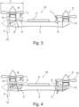
- Fig.3 is the same configuration as in Fig.2 so that reference can be made to the corresponding description.
- the propellers on the pivotable drive device 12 and the non-pivotable drive device 9 each convey a vertical air flow L downwards in the lift position B.
- This air flow L strikes an impact surface P on the pylon device 2.
- the impact surface P is to be understood here primarily schematically, since the air L strikes the pylon device 2, among other things, below a rotating surface F of the propeller.
- the conveyed air L strikes primarily the part of the pylon device 2 that lies in a vertical projection of the rotating surface F onto the top of the pylon device 2.
- a first inlet opening 6 of an air guiding device 5 is arranged so that the conveyed air L can partly enter through the first inlet opening 6 so that it is conveyed through the air guiding device 5 into the interior of the pylon device 2. Due to the pressure of the conveyed air L at the first inlet opening 6, additional air conveying measures can be dispensed with in many cases. However, it is basically possible to arrange fans in the flow path through the air guiding device, for example, which in the Figure 4 are not shown.
- the first inlet opening 6 can also have a rounded inlet in order to minimize flow losses at the inlet.
- the first inlet opening can also be designed as a NACA inlet (see Figures 1 and 6 ).
- the air conveyed in the air guiding device 5 can be used, for example, to cool an electric motor 13 that drives the propeller.
- the electric motor 13 is arranged in the pivotable nacelle device 1.
- an inverter can be arranged in the non-pivotable part, i.e. the pylon device 2.
- a similarly acting device with a first inlet opening 6 and with a subsequent air guiding device 5 is also arranged in the rear region of the pylon device 2, so that the air conveyed by the non-pivoting drive device 9 can also be used as cooling air for the non-pivoting drive device 9.
- the axis of rotation D of the nacelle device 1 is arranged in the wall of the pylon device 2.
- the axis of rotation D can also be arranged differently.
- the nacelle device 1 can be pivoted by means of the pivoting device 3 about the axis of rotation D between a first position, in particular the propulsion position A, and a second position, in particular the buoyancy position B, relative to the pylon device 2.
- the axis of rotation D can, however, be arranged within the pylon device 2 or the nacelle device 1, wherein the axis of rotation D can in particular lie on or in an axial center plane of the pylon device 2.
- the pivoting of the nacelle device can take place in a spatially compact manner.
- the pivoting device 3 can also be part of the pylon device 2, in particular integrated into it. This can mean, for example, that parts of the wall of the pylon device are also pivoted.
- An air guiding device inside the pylon device 2 can be continuously flowed through by air in the first position A and in the second position B of the nacelle device 1, in particular also in positions in between.
- the air guiding device can have at least one outlet opening, wherein the outlet opening has a first outlet region in the side wall of the nacelle device 2 and a second outlet region in the axial end region of the nacelle device 1.
- the outlet opening can be used, for example, to separate particles that can be carried away due to acceleration through centrifugal forces.
- the outlet openings can also be used to regulate the air mass flow.
- the nacelle device 1 can be designed such that when coupled to an air guiding device 5 in the interior of the pylon device 2, air can always flow through it, namely in the first position A and in the second position B of the nacelle device 1 and also in positions in between.
- the interior of the pylon device 2 is at least partially designed as an air guiding device 5.
- the nacelle device 1 can have at least one outlet opening, wherein the outlet opening has a first outlet region in the side wall and a second outlet region in the axial end region of the air guiding device. Air can thus flow out of the nacelle device 1 in different directions (or also flow in, depending on the main flow direction). This arrangement of the outlet region enables air to flow through the nacelle device and the pylon device 2 in any pivoting position of the nacelle device 1.
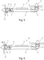
- the pivotable drive device 12 is shown here in the propulsion position B, so that no air L is conveyed from the propeller into the first inlet opening. Instead, the air L is conveyed to the rear.
- the pylon device 2 has a second inlet opening 7, which serves as a NACA inlet (see Figure 1 ). This allows air flowing past the pylon device 2 to be efficiently guided as cooling air into the interior of the air guiding device 5.
- a NACA inlet see Figure 1
- the non-pivotable drive device 9 is designed here without a second inlet opening 7, but can in principle also have such an opening.
- FIG 6 is a further variation of the embodiment according to Figure 4 , wherein the pivotable drive device 12 is in the propulsion position B, so that no air L is conveyed by the propeller into the first inlet opening. Rather, the air L is conveyed to the rear.
- the first inlet opening 6, which receives the vertically downward air flow L in the lift position A, is here equipped with a NACA inlet (see Figure 1 ) so that air flowing along the pylon device 2 can be efficiently guided into the interior of the pylon device 2.
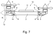
- a filter device 8 can be used to filter out particles from the air flowing through the first inlet opening 6. This prevents, in particular, an accumulation of such particles in the air-cooled electric motor 13 or at least minimizes the accumulation.
- the filter can also be designed as a separator (e.g. a cyclone).
- the collected or separated particles can then be discharged from the pylon device via an outlet opening 14.
- the first inlet opening 6 and the second inlet opening 7 are in the Fig. 3 to 7 shown as permanently open. It is basically possible to provide the inlet openings 6, 7 with a controllable door that can close the inlet openings 6, 7 in straight flight. This reduces the flow resistance when the aircraft is in straight flight.
- Fig. 8A to 8C is a variation of the embodiment according to Fig.4 so that reference can be made to the above description.
- the inverter 15 can be arranged in the pylon device 2 and coupled to the electric motor 13 in the pivotable nacelle device 1. Cooling air can be guided from the air guiding device 5 to the inverter 15 via a channel.
- the inverter 15 can also have several parts 15 ⁇ , 15", of which one part 15' is arranged in the adjustable nacelle device 1, the other part 15" in the pylon device 2.
- the cooling of the inverter 15 ⁇ , 15" can then take place as described in connection with the Figures 8A and 8B described.
Landscapes
- Engineering & Computer Science (AREA)
- Aviation & Aerospace Engineering (AREA)
- Mechanical Engineering (AREA)
- Chemical & Material Sciences (AREA)
- Combustion & Propulsion (AREA)
- Structures Of Non-Positive Displacement Pumps (AREA)
- Wind Motors (AREA)
Abstract
Description
- Die Erfindung betrifft eine Luftleitvorrichtung eines Senkrecht-Start- und - Landungsluftfahrzeugs mit den Merkmalen des Anspruchs 1 und ein Senkrecht-Start und -Landungsluftfahrzeug mit den Merkmalen des Anspruchs 10.
- Luftfahrzeuge, die senkrecht starten und landen können (im Englischen: VTOL: vertical take off and landing), sind grundsätzlich bekannt. Wird als Antriebsvorrichtung eines solchen Luftfahrzeuges ein elektrischer Antrieb verwendet, so wird dieses auch als eVTOL Luftfahrzeug bezeichnet. Gerade für den Einsatz von Luftfahrzeugen im städtischen Bereich (im Englischen: UAM: urban air mobility) sind solche Luftfahrzeuge von erheblichem Interesse.
- Dabei kommen grundsätzlich unterschiedliche Bauformen zum Einsatz, wie z.B. reine Drehflügler oder Bauformen mit schwenkbaren Tragflächen oder schwenkbaren Antrieben.
- Bei einer Ausführung mit schwenkbaren Antrieben werden diese z.B. mittels einer schwenkbaren Nacellevorrichtung (auch als Gondeln bezeichnet) von einer Auftriebsposition in eine Vortriebsposition gebracht. Die Nacellevorrichtungen sind dabei über eine Pylonvorrichtung mit einer Tragfläche verbunden, wobei die Verschwenkung um eine Achse am Gehäuse der Pylonvorrichtung erfolgt.
- Es besteht die Aufgabe, verbesserte Nacellevorrichtungen zu schaffen, die insbesondere eine effiziente Strömungsführung in der Auftriebsposition erlaubt.
- Die Aufgabe wird durch eine Luftleitvorrichtung für ein Senkrecht-Start- und - Landungsluftfahrzeug mit den Merkmalen des Anspruchs 1 gelöst.
- Dabei ist eine Nacellevorrichtung mit einer Antriebsvorrichtung des Senkrecht-Start- und -Landungsluftfahrzeugs über eine Pylonvorrichtung mit einer Tragfläche des Senkrecht-Start- und -Landungsluftfahrzeugs verbunden. Mittels einer Verschwenkvorrichtung ist die Nacellevorrichtung mit der Antriebsvorrichtung um eine Drehachse zwischen einer Vortriebsposition und einer Auftriebsposition relativ zur Pylonvorrichtung verschwenkbar.
- Eine erste Einlassöffnung einer Luftleitvorrichtung (z.B.: Lufteinlass- und luftführungseinrichtung) ist an der Pylonvorrichtung in dem Bereich angeordnet, in dem die von der Antriebsvorrichtung in der Auftriebsposition geförderte Luft auf die Pylonvorrichtung auftrifft. Damit kann die von der Antriebsvorrichtung geförderte Luft über die erste Einlassöffnung der Luftleitvorrichtung in das Innere der der Pylonvorrichtung und auch der Antriebsvorrichtung geführt werden, um dort z.B. eine kühlende Wirkung zu entfalten.
- Insbesondere kann die Antriebsvorrichtung somit einen Propeller aufweisen, der im Betrieb eine Drehfläche aufweist, wobei die erste Einlassöffnung in dem Bereich der senkrechten Projektion der Drehfläche auf die Oberseite der Pylonvorrichtung liegt. Dies ist der Bereich der aufprallenden Luft und / oder der Bereich des maximal vom Propeller erzeugten Druckes, die von der Antriebsvorrichtung in der Auftriebsposition nach unten gefördert wird und wie benötigt umgeleitet wird, um Komponenten zu kühlen. Wenn dies erste Einlassöffnung an der radialen Position des maximalen Propellerdrucks im Schwebeflug angeordnet ist, liegt eine hohe Druckdifferenz an, was sich positiv auf den Kühlmassenstrom auswirkt.
- Somit kann die von der Antriebsvorrichtung über die erste Einlassöffnung eingeführte Luft als Kühlluft zur Antriebsvorrichtung geführt werden. Somit kann auf die Pylonvorrichtung aufprallende Luft z.B. einen Elektromotor kühlen, der einen Propeller der Antriebsvorrichtung antreibt. Durch den Abstand zwischen Einlassposition und Antrieb ergibt sich auch eine verlustärmere Verteilungsmöglichkeit des Luftmassenstroms auf mehrere Komponenten.
- Damit die erste Einlassöffnung, d.h. bei einer pyloninterne Luftführung auch in der Vortriebsposition Luft aufnehmen kann, ist die erste Einlassöffnung in einer Ausführungsform mindestens teilweise als NACA-Einlauf ausgebildet. Diese Einläufe weisen u.a. konvergierende Seitenwände auf.
- Eine weitere Ausführungsform der Luftleitvorrichtung weist eine zweite Einlassöffnung auf, über die Kühlluft insbesondere von der Unterseite der Pylonvorrichtung in der Vortriebsposition zur Antriebsvorrichtung führbar ist. Auch die zweite Einlassöffnung kann mindestens teilweise als NACA-Einlauf ausgebildet sein oder auch als konventioneller Pitot-Einlass.
- Da die Luftleitvorrichtung Luft aus der Umgebung in das Innere der Pylonvorrichtung und / oder die Antriebsvorrichtung leitet, könnte auch Staub und andere Verunreinigungen in das Innere gelangen. Daher ist in einer Ausführungsform mindestens eine Filtervorrichtung zur Filterung und / oder eine Abscheidungsvorrichtung von Partikeln aus der Luft vorgesehen, die durch die erste Einlassöffnung und / oder die zweite Einlassöffnung eingeführt werden.
- Für eine besonders kompakte Bauform ist die Luftleitvorrichtung im Inneren der Pylonvorrichtung angeordnet.
- Bei einer weiteren Ausführungsform ist in einem nicht-schwenkbaren Bereich der Pylonvorrichtung und / oder in der schwenkbaren Nacellevorrichtung ein Inverter und jeweils ein Teil eines Inverters angeordnet, wobei im schwenkbaren Bereich der Pylonvorrichtung ein Elektromotor angeordnet ist. Da ein Inverter einen Kühlbedarf hat, kann der Inverter in jedem Fall mit der Kühlluft versorgt werden, die aus der Luftleitvorrichtung stammt.
in einem nicht-schwenkbaren Bereich der Pylonvorrichtung ein Inverter und im schwenkbaren Bereich der Pylonvorrichtung ein elektrischer Motor angeordnet. Dies ermöglicht u.a. die effiziente Kühlung von Komponenten (insbesondere die Verwendung von luftgekühlten Elektromotoren) ohne zusätzlichen Lüfter und eine effiziente und verlustarme Aufteilung des Kühlluftstroms auf unterschiedliche Komponenten (z.B. Motor und Inverter). Auch können Komponenten integriert werden, die einen relativ hohen Druckverlust aufweisen, wie z.B. Filter oder Partikelabscheider. - Die erste Einlassöffnung und / oder die zweite Einlassöffnung kann in einer Ausführungsform mit einer ansteuerbaren Tür (z.B. in Form einer Klappe) verschließbar sein. Im Fall des Geradausflugs (Cruise) könnte die erste Einlassöffnung verschlossen sein, da dabei keine in vertikaler Richtung geförderte Luft vorliegt. Der Luftwiderstand würde in diesem Fall reduziert werden. Auch könnte während einer Stillstandszeit des Luftfahrzeugs die Einlassöffnung verschlossen werden. Ferner kann die ansteuerbare Tür im geöffneten Zustand und bei geeigneter Luftführung auch als weiteres Luftleitmittel dienen, um Kühlluft aufzunehmen und sie an die gewünschte Stelle zu leiten.
- Die Aufgabe wird auch durch ein Senkrecht- Start- und -Landungsluftfahrzeug mit den Merkmalen des Anspruchs 10 gelöst.
- Dabei kann die Antriebseinheit und die Luftführung über eine entsprechende Dichtung, insbesondere mit einer Verschwenkvorrichtung gekoppelt sein, die als Hebelgetriebe ausgebildet ist, insbesondere mit einem hydraulisch, elektrisch oder pneumatisch angetriebenen Hebelgetriebe. Diese Art von Hebelgetrieben erlauben die Übertragung größerer Kräfte, so dass auch eine schwere Nacellevorrichtung bewegt und in Position gehalten werden kann.
- Auch kann die Pylonvorrichtung mit einer nicht-verschwenkbaren Antriebsvorrichtung verbunden sein, die zusätzlich zur verschwenkbaren Antriebsvorrichtung Auftrieb verleihen kann.
- Im Zusammenhang mit den in den Figuren werden Ausführungsbeispiele erläutert. Dabei zeigt
-
Figur 1 eine Teilansicht eines bekannten Luftfahrzeugs mit Einlassöffnungen für Luft; -
Figur 2 eine schematische Ansicht eines Senkrecht-Start und - Landungsluftfahrzeugs; -
Figur 3 eine schematische Darstellung der Luftführung bei dem Senkrecht-Start und -Landungsluftfahrzeug; -
Figur 4 eine schematische Darstellung der Luftführung einer Ausführungsform des Senkrecht-Start und -Landungsluftfahrzeugs gemäßFigur 3 ; -
Figur 5 eine schematische Darstellung einer weiteren Ausführungsform des Senkrecht-Start und -Landungsluftfahrzeugs in Vortriebsposition mit einer zweiten Einlassöffnung für Luft; -
Figur 6 eine schematische Darstellung einer weiteren Ausführungsform des Senkrecht-Start und -Landungsluftfahrzeugs Vortriebsposition mit einem NACA-Einlass an einer ersten Einlassöffnung; -
Figur 7 eine Variation der Ausführungsform gemäßFigur 3 mit einer Vorrichtung zur Filterung und Abscheidung von Partikeln aus der Luft; -
Figur 8A eine Detaildarstellung einer Variation der Ausführungsform gemäßFig. 4 mit einem Inverter in der verschwenkbaren Nacellevorrichtung. -
Figur 8B eine Detaildarstellung einer Variation der Ausführungsform gemäßFig. 4 mit einem Inverter in der Pylonvorrichtung. -
Figur 8C eine Detaildarstellung einer Variation der Ausführungsform gemäßFig. 4 mit einem Teil eines Inverters in der verschwenkbaren Nacellevorrichtung und einem anderen Teil des Inverters in der Pylonvorrichtung. - In
Figur 1 ist ein an sich bekanntes Luftfahrzeug 20 dargestellt, das mit einem Propeller 12 angetrieben wird. Der Propeller 12 ist hier so ausgebildet, dass er nicht für den Senkrechtstart und eine Senkrechtlandung ausgebildet ist. - Aber
Figur 1 zeigt, dass dieses Luftfahrzeug 20 hinter der Drehebene des Propellers mehrere Lufteinlässe 21 (sichtbar sind hier zwei) aufweist. Damit wird vom Propeller geförderte Luft in Richtung der Lufteinlässe gefördert. - An der Längsseite des Luftfahrzeugs ist ein weiterer Lufteinlass in Form eines an sich bekannten NACA-Einlasses 22 angeordnet, der längs des Rumpfes des Luftfahrzeugs 20 entlangströmende Luft aufnimmt.
- Ein NACA-Einlass 22 ist ein strömungsgünstiger Lufteinlass in der Außenhaut von Fahrzeugen. Durch schräge Seitenkanten - in
Figur 1 erkennbar - werden Luftwirbel erzeugt, die eine langsame Grenzschichtströmung verdrängen. Dies bewirkt eine Geschwindigkeitskomponenten nach Innen und induziert einen Massenstrom in den NACA-Einlass 22. Deshalb kann der der NACA-Einlass 22 für einen gegebenen Luftstrom klein ausgeführt werden und vergrößert den Luftwiderstand nur wenig. -
Figur 2 hingegen zeigt ein Senkrecht-Start- und -Landungsluftfahrzeug 10 (häufig auch nur als Senkrechtstarter bezeichnet), das grundsätzlich anders aufgebaut ist als das Luftfahrzeug 20 gemäßFigur 1 . - Dabei ist aus Gründen der Übersichtlichkeit vor allem die Tragfläche 11 und die an der Unterseite der Tragfläche 11 angeordnete Pylonvorrichtung 2 dargestellt. Insbesondere die Passagierkabine ist somit hier nicht dargestellt. In anderen, hier nicht dargestellten Ausführungsformen kann die Pylonvorrichtung 2 auch an der Oberseite der Tragfläche 11 angeordnet sein.
- Die hier dargestellte Ausführungsform ist ein Senkrecht-Start- und - Landungsluftfahrzeug 10, bei dem eine Antriebsvorrichtung 12, hier ein Rotor oder Propeller, verschwenkbar mit einer Nacellevorrichtung 1 gekoppelt ist. Angetrieben wird der Rotor über einen Elektromotor 13.
- Für einen Flug in der Horizontalen, d.h. einer Vortriebsposition A (gestrichelt dargestellt), ist der Rotor 12 an der Vorderseite der Pylonvorrichtung 2 so ausgerichtet, dass er im Betrieb Luft horizontal in Richtung der Tragfläche 11 bewegt, so dass ein Auftrieb entsteht. Dies ist die erste Position A (Vortriebsposition) der Antriebsvorrichtung 12. Bei konventionellen Luftfahrzeugen 20 ist das die Position, in der gestartet und gelandet wird, wobei jeweils ausgedehnte Start- und Landebahnen benötigt werden.
- Damit ein Senkrecht-Start- und -Landungsluftfahrzeug 10 in der Vertikalen starten und landen kann, wird eine Antriebsvorrichtung 12 benötigt, die auch Schub in der Vertikalen erzeugen kann. Die Antriebsvorrichtung 12 ist hier an einer Nacellevorrichtung 1 (auch Gondel genannt) angeordnet, die als ein relativ zur Pylonvorrichtung 2 bewegliche Gehäuse ausgebildet ist.
- Bei der in
Figur 2 mit durchgezogenen Linien dargestellten Ausführungsform wird dies dadurch erreicht, dass die Antriebsvorrichtung 12 in eine zweite Position B (Auftriebsposition) verschwenkt wird, so dass die vom Rotor geförderte Luft einen Schub nach unten erzeugt. Die Verschwenkung erfolgt dabei relativ zur Pylonvorrichtung 2 nach oben (hier im Uhrzeigersinn). - Für Starten und Landen kann zwischen den beiden Positionen A und B gewechselt werden. Eine solche Verschwenkung ist an sich bekannt.
- Bei der hier dargestellten Ausführungsform ist die Drehachse D der Verschwenkung am Gehäuse der Pylonvorrichtung 2 angeordnet. Die Nacellevorrichtung 1 - und damit die Antriebsvorrichtung 12 - können so relativ zur Pylonvorrichtung 2 verschwenkt werden.
- Eine Verschwenkvorrichtung 3, mit der die Verschwenkung der Nacellevorrichtung 1 bewirkt wird, ist in der
Figur 2 aus Gründen der Übersichtlichkeit nur schematisch im Inneren der Pylonvorrichtung 2 dargestellt. Diese kann z.B. als Hebelgetriebe ausgeführt sein. - Des Weiteren weist die darstellte Ausführungsform des Senkrecht-Start- und - Landungsluftfahrzeugs 10 auch eine nicht-verschwenkbare Antriebsvorrichtung 9 auf, die nur für den Auftrieb eingesetzt wird. Auch diese wird mit einem Elektromotor 13 angetrieben.
- In der
Fig. 3 ist die gleiche Konfiguration wie inFig. 2 dargestellt, so dass auf die entsprechende Beschreibung Bezug genommen werden kann. - Die Propeller an der verschwenkbaren Antriebsvorrichtung 12 und der nicht-verschwenkbaren Antriebsvorrichtung 9 fördern jeweils in der Auftriebsposition B einen vertikalen Luftstrom L nach unten. Dieser Luftstrom L trifft auf einer Prallfläche P auf der Pylonvorrichtung 2 auf. Die Prallfläche P ist hier vor allem schematisch zu verstehen, da die Luft L unterhalb einer Drehfläche F des Propellers u.a. auf die Pylonvorrichtung 2 trifft. Die geförderte Luft L trifft vor allem auf den Teil der Pylonvorrichtung 2, der in einer senkrechten Projektion der Drehfläche F auf die Oberseite der Pylonvorrichtung 2 liegt.
- In diesem Bereich der Pylonvorrichtung 2 ist in der Ausführungsform gemäß
Figur 4 eine erste Einlassöffnung 6 einer Luftleitvorrichtung 5 angeordnet, so dass die geförderte Luft L zum Teil durch die erste Einlassöffnung 6 eintreten kann, so dass sie durch die Luftleitvorrichtung 5 in das Innere der Pylonvorrichtung 2 gefördert wird. Auf Grund des Drucks der geförderten Luft L an der ersten Einlassöffnung 6 kann auf zusätzliche Luftfördermaßnahmen in vielen Fällen verzichtet werden. Es ist grundsätzlich aber möglich, im Strömungsverlauf durch die Luftleitvorrichtung z.B. Ventilatoren anzuordnen, die in derFigur 4 nicht dargestellt sind. Auch kann die erste Einlassöffnung 6 einen gerundeten Einlass aufweisen, um Strömungsverluste am Einlass zu minimieren. Auch kann die erste Einlassöffnung als NACA-Einlass ausgebildet sein (sieheFiguren 1 und6 ). - Die in der Luftleitvorrichtung 5 geförderte Luft kann z.B. zur Kühlung eines Elektromotors 13 dienen, der den Propeller antreibt. In der hier dargestellten Ausführungsform ist der Elektromotor 13 in der schwenkbaren Nacellevorrichtung 1 angeordnet. In einer alternativen, hier nicht dargestellten Ausführungsform kann im nicht-schwenkbaren Teil, d.h. der Pylonvorrichtung 2 ein Inverter angeordnet sein.
- Eine gleichwirkende Vorrichtung mit einer ersten Einlassöffnung 6 und mit einer anschließenden Luftleitvorrichtung 5 ist auch im hinteren Bereich der Pylonvorrichtung 2 angeordnet, so dass auch die von der nicht-verschwenkbaren Antriebsvorrichtung 9 geförderte Luft als Kühlluft für die nicht-verschwenkbare Antriebsvorrichtung 9 verwendbar ist.
- Bei der Ausführungsform der
Figur 4 ist die Drehachse D der Nacellevorrichtung 1 in der Wandung der Pylonvorrichtung 2 angeordnet. Alternativ kann die Drehachse D auch anders angeordnet sein. Grundsätzlich ist die Nacellevorrichtung 1 mittels der Verschwenkvorrichtung 3 um die Drehachse D zwischen einer ersten Position, insbesondere der Vortriebsposition A und einer zweiten Position, insbesondere der Auftriebsposition B, relativ zur Pylonvorrichtung 2 verschwenkbar. Dabei kann die Drehachse D aber innerhalb der Pylonvorrichtung 2 oder der Nacellevorrichtung 1 angeordnet sein, wobei die Drehachse D insbesondere auf oder in einer axialen Mittelebene der Pylonvorrichtung 2 liegen kann. Durch die Verlagerung der Drehachse D in das Innere z.B. der Pylonvorrichtung 2 kann die Verschwenkung der Nacellevorrichtung räumlich kompakt erfolgen. Dabei kann die Verschwenkvorrichtung 3 auch ein Teil der Pylonvorrichtung 2 sein, insbesondere in diese integriert sein. Dies kann z.B. bedeuten, dass Teile der Wandung der Pylonvorrichtung mitverschwenkt werden. Eine Luftführungsvorrichtung im Inneren der Pylonvorrichtung 2 kann in der ersten Position A und in der zweiten Position B der Nacellevorrichtung 1, insbesondere auch in Positionen dazwischen, durchgängig von Luft durchströmbar sein. Dazu kann die Luftführungsvorrichtung mindestens eine Auslassöffnung aufweisen, wobei die Auslassöffnung einen ersten Auslassbereich in der Seitenwand der Nacellevorrichtung 2 und einen zweiten Auslassbereich im axialen Endbereich der Nacellevorrichtung 1 aufweisen. Die Auslassöffnung kann z.B. dem Abscheiden von Partikeln dienen, die auf Grund einer Beschleunigung durch Zentrifugalkräfte ausgetragen werden können. Die Auslassöffnungen können auch der Regulierung des Luftmassenstroms dienen. - Ferner kann die Nacellevorrichtung 1 so ausgebildet sein, dass bei einer Kopplung mit einer Luftleitvorrichtung 5 im Inneren der Pylonvorrichtung 2 diese immer von Luft durchströmbar ist, und zwar in der ersten Position A und in der zweiten Position B der Nacellevorrichtung 1 und auch in Positionen dazwischen. Für eine besonders effiziente Ausgestaltung ist das Innere der Pylonvorrichtung 2 mindestens teilweise als Luftleitvorrichtung 5 ausgebildet. Dabei kann die Nacellevorrichtung 1 in einer Ausführungsform mindestens eine Auslassöffnung aufweisen, wobei die Auslassöffnung einen ersten Auslassbereich in der Seitenwand und einen zweiten Auslassbereich im axialen Endbereich der Luftleitungsvorrichtung aufweist. Somit kann Luft in unterschiedlichen Richtungen aus der Nacellevorrichtung 1 ausströmen (oder auch einströmen, je nach Hauptströmungsrichtung). Diese Anordnung des Auslassbereichs ermöglicht, dass in jeder Schwenklage der Nacellevorrichtung 1 Luft durch die Nacellevorrichtung und die Pylonvorrichtung 2 strömen kann.
- Diese Art der Anordnung der Drehachse D und / oder die Ausbildung der Nacellevorrichtung 1 kann auch in allen anderen hier beschriebenen Ausführungsformen verwendet (siehe z.B.
Figuren 5 bis 7 ) werden. - In der
Figur 5 ist eine Abwandlung der Ausführungsform gemäßFigur 4 dargestellt, so dass auf die entsprechende Beschreibung Bezug genommen wird. - Die verschwenkbare Antriebsvorrichtung 12 ist hier in der Vortriebsposition B dargestellt, so dass keine Luft L vom Propeller in die erste Einlassöffnung gefördert wird. Vielmehr wird die Luft L nach hinten gefördert.
- Die Pylonvorrichtung 2 weist eine zweite Einlassöffnung 7 auf, die als NACA-Einlass (siehe
Figur 1 ) ausgebildet ist. Damit kann an der Pylonvorrichtung 2 vorbeiströmende Luft effizient als Kühlluft in das Innere der Luftleitvorrichtung 5 geführt werden. Je nach den Druckverhältnissen in der Luftleitvorrichtung 5 kann es sinnvoll sein, dass in dieser Betriebsweise der Weg zur ersten Einlassöffnung 6 in der Luftleitvorrichtung 5 - z.B. durch eine Klappe oder ein Ventil - verschlossen wird, damit keine Kühlluft abströmen kann. - Die nicht-verschwenkbare Antriebsvorrichtung 9 ist hier ohne zweite Einlassöffnung 7 ausgebildet, kann aber grundsätzlich auch eine solche aufweisen.
- In der
Figur 6 ist eine weitere Variation der Ausführungsform gemäßFigur 4 dargestellt, wobei sich die verschwenkbare Antriebsvorrichtung 12 in der Vortriebsposition B befindet, so dass keine Luft L vom Propeller in die erste Einlassöffnung gefördert wird. Vielmehr wird die Luft L nach hinten gefördert. - Die erste Einlassöffnung 6, die in der Auftriebsposition A den vertikal nach unten gerichteten Luftstrom L aufnimmt, ist hier mit einem NACA-Einlass (siehe
Figur 1 ) versehen, so dass an der Pylonvorrichtung 2 entlangströmende Luft effizient in das Innere der Pylonvorrichtung 2 führbar ist. - In der
Figur 7 ist eine weitere Ausführungsform dargestellt, die zusätzlich zu den Ausführungsformen gemäß derFiguren 3 bis 6 in der Luftleitvorrichtung 5 der verschwenkbaren Antriebsvorrichtung 12 und der nicht-verschwenkbaren Antriebsvorrichtung 9 eine Filtervorrichtung 8 aufweist, mit der Partikel aus der durch die erste Einlassöffnung 6 strömende Luft herausgefiltert werden können. Damit wird insbesondere eine Ansammlung von solchen Partikeln im luft-gekühlten Elektromotor 13 verhindert oder zumindest wird die Ansammlung minimiert. Der Filter kann auch als Abscheider (z.B. ein Zyklon) ausgebildet sein. - Die aufgefangenen oder abgeschiedenen Partikel können dann über eine Auslassöffnung 14 aus der Pylonvorrichtung ausgeschleust werden.
- Die erste Einlassöffnung 6 und die zweite Einlassöffnung 7 sind in den
Fig. 3 bis 7 als ständig offen dargestellt. Es ist grundsätzlich möglich, die Einlassöffnungen 6, 7 mit einer ansteuerbaren Tür zu versehen, die die Einlassöffnungen 6, 7 im Geradeausflug verschließen kann. Damit wird der Strömungswiderstand reduziert, wenn das Luftfahrzeug sich im Geradeausflug befindet. - In den
Fig. 8A bis 8C ist eine Variation der Ausführungsform gemäßFig. 4 dargestellt, so dass auf die obige Beschreibung Bezug genommen werden kann. - In der ersten Variante gemäß
Fig. 8A sind der Elektromotor 13 und ein Inverter 15 gemeinsam in der verschwenkbaren Nacellevorrichtung 1 angeordnet. Die Kühlluft wird über die Luftleitvorrichtung 5 zu beiden Komponenten geführt. - Wie in der
Fig. 8B dargestellt, ist es aber auch möglich, dass der Inverter 15 in der Pylonvorrichtung 2 angeordnet ist und mit dem Elektromotor 13 in der verschwenkbaren Nacellevorrichtung 1 gekoppelt ist. Über einen Kanal kann Kühlluft aus der Luftleitvorrichtung 5 zu dem Inverter 15 geführt werden. - Der Inverter 15 kann aber auch mehrere Teile 15`, 15" aufweisen, von denen ein Teil 15' in der verstellbaren Nacellevorrichtung 1, der andere Teil 15" in der Pylonvorrichtung 2 angeordnet ist. Die Kühlung des Inverter 15`, 15" kann dann so erfolgen, wie das im Zusammenhang mit den
Figuren 8A und 8B beschrieben ist. -
- 1
- Nacellevorrichtung
- 2
- Pylonvorrichtung
- 3
- Verschwenkvorrichtung
- 5
- Luftleitvorrichtung
- 6
- erste Einlassöffnung
- 7
- zweite Einlassöffnung
- 8
- Filtervorrichtung
- 9
- nicht-verschwenkbare Antriebsvorrichtung
- 10
- Senkrecht-Start- und -Landungsluftfahrzeug
- 11
- Tragfläche
- 12
- Antriebvorrichtung, Rotor
- 13
- Elektromotor
- 14
- Auslassöffnung für Partikel
- 15
- Inverter
- 15'
- erster Teil eines Inverters
- 15"
- zweiter Teil eines Inverters
- 20
- Luftfahrzeug
- 21
- Lufteinlass
- 22
- NACA-Einlass
- A
- Vortriebsposition der Antriebsvorrichtung
- B
- Auftriebsposition der Antriebsvorrichtung
- D
- Drehachse der verschwenkbaren Nacellevorrichtung
- F
- Drehfläche des Propellers
- L
- von Propeller geförderte Luft
- P
- Aufprallfläche auf Pylonvorrichtung
Claims (12)
- Luftleitvorrichtung (5) für ein Senkrecht-Start- und -Landungsluftfahrzeug (10), wobei eine Nacellevorrichtung (1) mit einer Antriebsvorrichtung (12) über eine Pylonvorrichtung (2) mit einer Tragfläche (1) des Senkrecht-Start- und - Landungsluftfahrzeugs (10) verbunden ist und mittels einer Verschwenkvorrichtung (3) um eine Drehachse (D) zwischen einer Vortriebsposition (A) und einer Auftriebsposition (B) relativ zur Pylonvorrichtung (2) verschwenkbar ist,
dadurch gekennzeichnet, dass
eine erste Einlassöffnung (6) der Luftleitvorrichtung (5) an der Pylonvorrichtung (2) in dem Bereich angeordnet ist, in dem die von der Antriebsvorrichtung (12) in der Auftriebsposition (B) geförderte Luft (L) auf die Pylonvorrichtung (2) im Bereich des maximal vom Propeller erzeugten Druckes auftrifft und dass die von der Antriebsvorrichtung (12) über die erste Einlassöffnung (6) eingeführte Luft als Kühlluft zur Antriebsvorrichtung (12) führbar ist. - Luftleitvorrichtung (5) nach Anspruch 1, dadurch gekennzeichnet, dass die Antriebsvorrichtung (12) einen Propeller aufweist und der im Betrieb eine Drehfläche (F) aufweist, wobei die erste Einlassöffnung (6) in dem Bereich der senkrechten Projektion der Drehfläche (F) auf die Oberseite der Pylonvorrichtung (2) liegt.
- Luftleitvorrichtung (5) nach mindestens einem der vorhergehenden Ansprüche, dadurch gekennzeichnet, dass die erste Einlassöffnung (6) mindestens teilweise als NACA-Einlauf ausgebildet ist.
- Luftleitvorrichtung (5) nach mindestens einem der vorhergehenden Ansprüche, gekennzeichnet durch eine zweite Einlassöffnung (7), über die Kühlluft, insbesondere von der Unterseite der Pylonvorrichtung (1), in der Vortriebsposition (A) zur Antriebsvorrichtung (12) führbar ist.
- Luftleitvorrichtung (5) nach Anspruch 4, dadurch gekennzeichnet, dass die zweite Einlassöffnung (7) mindestens teilweise als NACA-Einlauf ausgebildet ist.
- Luftleitvorrichtung (5) nach mindestens einem der vorhergehenden Ansprüche, gekennzeichnet durch mindestens eine Filtervorrichtung (8) zur Filterung und / oder eine Abscheidungsvorrichtung von Partikeln aus der Luft, die durch die erste Einlassöffnung (6) und / oder die zweite Einlassöffnung (7) eingeführt werden.
- Luftleitvorrichtung (5) nach mindestens einem der vorhergehenden Ansprüche, dadurch gekennzeichnet, dass diese im Inneren der Pylonvorrichtung (2) angeordnet ist.
- Luftleitvorrichtung (5) nach mindestens einem der vorhergehenden Ansprüche, dadurch gekennzeichnet, dass in einem nicht-schwenkbaren Bereich der Pylonvorrichtung (2) und / oder in der schwenkbaren Nacellevorrichtung (1) ein Inverter (15) und jeweils ein Teil eines Inverters (15`, 15") angeordnet ist, wobei im schwenkbaren Bereich der Pylonvorrichtung (2) ein Elektromotor (13) angeordnet ist.
- Luftleitvorrichtung (5) nach mindestens einem der vorhergehenden Ansprüche, dadurch gekennzeichnet, dass die erste Einlassöffnung (6) und / oder die zweite Einlassöffnung (7) mit einer ansteuerbaren Tür verschließbar ist.
- Senkrecht- Start- und -Landungsluftfahrzeug (10) mit mindestens einer Pylonvorrichtung (2) an einem Flügel (11), wobei die mindestens eine Pylonvorrichtung (2) eine Luftleitvorrichtung (5) nach mindestens einem der Ansprüche 1 bis 9 aufweist.
- Senkrecht- Start- und -Landungsluftfahrzeug (10) nach Anspruch 10, dadurch gekennzeichnet, dass die Antriebseinheit und ggf. die Luftführung (12) mit einer Verschwenkvorrichtung (3) gekoppelt ist, die als Hebelgetriebe ausgebildet ist, insbesondere mit einem hydraulisch, elektrisch oder pneumatisch angetriebenen Hebelgetriebe.
- Senkrecht-Start- und -Landungsluftfahrzeug (10) nach Anspruch 10 oder 11, dadurch kennzeichnet, dass die Pylonvorrichtung (2) mit einer nicht-verschwenkbaren Antriebsvorrichtung (9) verbunden ist.
Applications Claiming Priority (1)
| Application Number | Priority Date | Filing Date | Title |
|---|---|---|---|
| DE102022131799.4A DE102022131799A1 (de) | 2022-11-30 | 2022-11-30 | Luftleitvorrichtung eines Senkrecht-Start- und -Landungsluftfahrzeugs und ein Senkrecht-Start- und -Landungsluftfahrzeug |
Publications (1)
| Publication Number | Publication Date |
|---|---|
| EP4378829A1 true EP4378829A1 (de) | 2024-06-05 |
Family
ID=89029491
Family Applications (1)
| Application Number | Title | Priority Date | Filing Date |
|---|---|---|---|
| EP23213049.2A Withdrawn EP4378829A1 (de) | 2022-11-30 | 2023-11-29 | Luftleitvorrichtung eines senkrecht-start- und -landungsluftfahrzeugs und ein senkrecht-start- und -landungsluftfahrzeug |
Country Status (3)
| Country | Link |
|---|---|
| US (1) | US20240174356A1 (de) |
| EP (1) | EP4378829A1 (de) |
| DE (1) | DE102022131799A1 (de) |
Citations (5)
| Publication number | Priority date | Publication date | Assignee | Title |
|---|---|---|---|---|
| US20160200436A1 (en) * | 2013-08-13 | 2016-07-14 | U.S.A. As Represented By The Administrator Of The National Aeronautics And Space Administration | Tri-Rotor Aircraft Capable of Vertical Takeoff and Landing and Transitioning to Forward Flight |
| US20180105268A1 (en) * | 2016-10-18 | 2018-04-19 | Kitty Hawk Corporation | Ventilated rotor mounting boom for personal aircraft |
| WO2021222528A1 (en) * | 2020-05-01 | 2021-11-04 | Overair, Inc. | Adaptive cooling system for an aircraft |
| US20220041275A1 (en) * | 2020-08-07 | 2022-02-10 | Shanghai Autoflight Co., Ltd. | Vertical takeoff and landing aerial vehicle and cooling system |
| US20220194618A1 (en) * | 2020-12-22 | 2022-06-23 | Hyundai Motor Company | Air mobility vehicle |
Family Cites Families (12)
| Publication number | Priority date | Publication date | Assignee | Title |
|---|---|---|---|---|
| FR2791634B1 (fr) * | 1999-03-30 | 2001-06-15 | Eurocopter France | Perfectionnements aux aeronefs convertibles a rotors basculants |
| DE102012217469A1 (de) * | 2012-09-26 | 2014-03-27 | Siemens Aktiengesellschaft | Kühlsystem für Komponenten in (Luft-)Fahrzeugstrukturen |
| US9126678B2 (en) * | 2013-03-13 | 2015-09-08 | Bell Helicopter Textron Inc. | Spindle mounted tiltrotor pylon with fixed engine arrangement |
| DE102016125656B4 (de) * | 2016-12-23 | 2021-02-18 | Airbus Defence and Space GmbH | Luftfahrzeug mit einem Kühlsystem und Kühlverfahren |
| DE102018116170A1 (de) * | 2018-07-04 | 2020-01-09 | Dr. Ing. H.C. F. Porsche Aktiengesellschaft | Luftfahrzeug |
| US11866169B2 (en) * | 2020-08-07 | 2024-01-09 | Textron Innovations Inc. | System and method for supplying passively filtered ram air to a hydrogen fuel cell of a UAV |
| KR102552953B1 (ko) * | 2021-11-22 | 2023-07-06 | 한국항공우주연구원 | 전기추진항공기 |
| US12116209B2 (en) * | 2022-07-14 | 2024-10-15 | Intelligrated Headquarters, Llc | Conveyor roller integrated divert mechanism |
| US12509225B2 (en) * | 2022-10-06 | 2025-12-30 | Archer Aviation Inc. | Linked low pitch stop for tilting propellers |
| US11613350B1 (en) * | 2022-10-07 | 2023-03-28 | Archer Aviation, Inc. | Systems and methods for lifter motor cooling in eVTOL aircraft |
| DE102022131771A1 (de) * | 2022-11-30 | 2024-06-06 | Rolls-Royce Deutschland Ltd & Co Kg | Nacellevorrichtung mit Luftleitvorrichtung und Senkrecht-Start und -Landungsluftfahrzeug |
| US11679872B1 (en) * | 2022-12-12 | 2023-06-20 | Archer Aviation Inc. | Tilter motor cooling apparatus for vertical takeoff and landing aircraft and operating method of the same |
-
2022
- 2022-11-30 DE DE102022131799.4A patent/DE102022131799A1/de active Pending
-
2023
- 2023-11-28 US US18/522,211 patent/US20240174356A1/en not_active Abandoned
- 2023-11-29 EP EP23213049.2A patent/EP4378829A1/de not_active Withdrawn
Patent Citations (5)
| Publication number | Priority date | Publication date | Assignee | Title |
|---|---|---|---|---|
| US20160200436A1 (en) * | 2013-08-13 | 2016-07-14 | U.S.A. As Represented By The Administrator Of The National Aeronautics And Space Administration | Tri-Rotor Aircraft Capable of Vertical Takeoff and Landing and Transitioning to Forward Flight |
| US20180105268A1 (en) * | 2016-10-18 | 2018-04-19 | Kitty Hawk Corporation | Ventilated rotor mounting boom for personal aircraft |
| WO2021222528A1 (en) * | 2020-05-01 | 2021-11-04 | Overair, Inc. | Adaptive cooling system for an aircraft |
| US20220041275A1 (en) * | 2020-08-07 | 2022-02-10 | Shanghai Autoflight Co., Ltd. | Vertical takeoff and landing aerial vehicle and cooling system |
| US20220194618A1 (en) * | 2020-12-22 | 2022-06-23 | Hyundai Motor Company | Air mobility vehicle |
Also Published As
| Publication number | Publication date |
|---|---|
| US20240174356A1 (en) | 2024-05-30 |
| DE102022131799A1 (de) | 2024-06-06 |
Similar Documents
| Publication | Publication Date | Title |
|---|---|---|
| DE3407137C2 (de) | ||
| DE102016125656B4 (de) | Luftfahrzeug mit einem Kühlsystem und Kühlverfahren | |
| DE60223439T3 (de) | Doppelter Einlass eines Strahltriebwerks | |
| EP2285672B1 (de) | Frischlufteinlass für ein flugzeug | |
| DE102019112132B4 (de) | Luftfahrzeug | |
| EP1327758B1 (de) | Lufteinlauf-Vorrichtung für ein Hilfstriebwerk in einem Flugzeug | |
| CH665185A5 (de) | Drehfluegelflugkoerper. | |
| DE102019118023B3 (de) | Luftfahrzeug | |
| DE102021124376A1 (de) | Flugzeug zum vertikalen starten und landen sowie flügelvorrichtung | |
| DE102020113489B4 (de) | Luftfahrzeug | |
| DE102020113490B4 (de) | Luftfahrzeug | |
| EP4522480A1 (de) | Schienenfahrzeug | |
| EP4378830A1 (de) | Nacellevorrichtung mit luftleitvorrichtung und senkrecht-start und -landungsluftfahrzeug | |
| DE102008032789A1 (de) | Flugzeug mit zumindest zwei in Spannweitenrichtung der Flügel voneinander beabstandeten Antriebsmotoren | |
| DE102022131799A1 (de) | Luftleitvorrichtung eines Senkrecht-Start- und -Landungsluftfahrzeugs und ein Senkrecht-Start- und -Landungsluftfahrzeug | |
| DE102021124502A1 (de) | Flugzeug zum vertikalen starten und landen sowie flügelvorrichtung | |
| EP4153478A1 (de) | Luftfahrzeug | |
| DE69817467T2 (de) | Ausfahrbarer Ejektor-Mischer für eine Turbomaschine | |
| DE2952821A1 (de) | Verbesserte klappengestaltung fuer ein angetriebenes auftriebsystem mit ueberblasenen tragflaechenklappen | |
| DE3626979C2 (de) | ||
| DE3626973C2 (de) | ||
| DE102021202824B4 (de) | Luftmobilitätsfahrzeug | |
| DE102018007160B4 (de) | Propeller-Schubklappe | |
| DE102022131791A1 (de) | Nacellevorrichtung und Senkrecht-Start und -Landungsluftfahrzeug | |
| DE102023129326A1 (de) | Flugzeug |
Legal Events
| Date | Code | Title | Description |
|---|---|---|---|
| PUAI | Public reference made under article 153(3) epc to a published international application that has entered the european phase |
Free format text: ORIGINAL CODE: 0009012 |
|
| STAA | Information on the status of an ep patent application or granted ep patent |
Free format text: STATUS: THE APPLICATION HAS BEEN PUBLISHED |
|
| AK | Designated contracting states |
Kind code of ref document: A1 Designated state(s): AL AT BE BG CH CY CZ DE DK EE ES FI FR GB GR HR HU IE IS IT LI LT LU LV MC ME MK MT NL NO PL PT RO RS SE SI SK SM TR |
|
| STAA | Information on the status of an ep patent application or granted ep patent |
Free format text: STATUS: REQUEST FOR EXAMINATION WAS MADE |
|
| 17P | Request for examination filed |
Effective date: 20240705 |
|
| RBV | Designated contracting states (corrected) |
Designated state(s): AL AT BE BG CH CY CZ DE DK EE ES FI FR GB GR HR HU IE IS IT LI LT LU LV MC ME MK MT NL NO PL PT RO RS SE SI SK SM TR |
|
| STAA | Information on the status of an ep patent application or granted ep patent |
Free format text: STATUS: THE APPLICATION HAS BEEN WITHDRAWN |
|
| 18W | Application withdrawn |
Effective date: 20250121 |