EP4378665A2 - Vorrichtung zur trennung einer gehärteten harzschicht von einem harzträger in der generativen fertigung - Google Patents
Vorrichtung zur trennung einer gehärteten harzschicht von einem harzträger in der generativen fertigung Download PDFInfo
- Publication number
- EP4378665A2 EP4378665A2 EP24164879.9A EP24164879A EP4378665A2 EP 4378665 A2 EP4378665 A2 EP 4378665A2 EP 24164879 A EP24164879 A EP 24164879A EP 4378665 A2 EP4378665 A2 EP 4378665A2
- Authority
- EP
- European Patent Office
- Prior art keywords
- foil
- stage
- resin
- holddown
- support structure
- Prior art date
- Legal status (The legal status is an assumption and is not a legal conclusion. Google has not performed a legal analysis and makes no representation as to the accuracy of the status listed.)
- Pending
Links
Images





Classifications
-
- B—PERFORMING OPERATIONS; TRANSPORTING
- B29—WORKING OF PLASTICS; WORKING OF SUBSTANCES IN A PLASTIC STATE IN GENERAL
- B29C—SHAPING OR JOINING OF PLASTICS; SHAPING OF MATERIAL IN A PLASTIC STATE, NOT OTHERWISE PROVIDED FOR; AFTER-TREATMENT OF THE SHAPED PRODUCTS, e.g. REPAIRING
- B29C64/00—Additive manufacturing, i.e. manufacturing of three-dimensional [3D] objects by additive deposition, additive agglomeration or additive layering, e.g. by 3D printing, stereolithography or selective laser sintering
- B29C64/10—Processes of additive manufacturing
- B29C64/106—Processes of additive manufacturing using only liquids or viscous materials, e.g. depositing a continuous bead of viscous material
- B29C64/124—Processes of additive manufacturing using only liquids or viscous materials, e.g. depositing a continuous bead of viscous material using layers of liquid which are selectively solidified
-
- B—PERFORMING OPERATIONS; TRANSPORTING
- B29—WORKING OF PLASTICS; WORKING OF SUBSTANCES IN A PLASTIC STATE IN GENERAL
- B29C—SHAPING OR JOINING OF PLASTICS; SHAPING OF MATERIAL IN A PLASTIC STATE, NOT OTHERWISE PROVIDED FOR; AFTER-TREATMENT OF THE SHAPED PRODUCTS, e.g. REPAIRING
- B29C64/00—Additive manufacturing, i.e. manufacturing of three-dimensional [3D] objects by additive deposition, additive agglomeration or additive layering, e.g. by 3D printing, stereolithography or selective laser sintering
- B29C64/10—Processes of additive manufacturing
- B29C64/106—Processes of additive manufacturing using only liquids or viscous materials, e.g. depositing a continuous bead of viscous material
- B29C64/124—Processes of additive manufacturing using only liquids or viscous materials, e.g. depositing a continuous bead of viscous material using layers of liquid which are selectively solidified
- B29C64/129—Processes of additive manufacturing using only liquids or viscous materials, e.g. depositing a continuous bead of viscous material using layers of liquid which are selectively solidified characterised by the energy source therefor, e.g. by global irradiation combined with a mask
-
- B—PERFORMING OPERATIONS; TRANSPORTING
- B29—WORKING OF PLASTICS; WORKING OF SUBSTANCES IN A PLASTIC STATE IN GENERAL
- B29C—SHAPING OR JOINING OF PLASTICS; SHAPING OF MATERIAL IN A PLASTIC STATE, NOT OTHERWISE PROVIDED FOR; AFTER-TREATMENT OF THE SHAPED PRODUCTS, e.g. REPAIRING
- B29C64/00—Additive manufacturing, i.e. manufacturing of three-dimensional [3D] objects by additive deposition, additive agglomeration or additive layering, e.g. by 3D printing, stereolithography or selective laser sintering
- B29C64/10—Processes of additive manufacturing
- B29C64/106—Processes of additive manufacturing using only liquids or viscous materials, e.g. depositing a continuous bead of viscous material
- B29C64/124—Processes of additive manufacturing using only liquids or viscous materials, e.g. depositing a continuous bead of viscous material using layers of liquid which are selectively solidified
- B29C64/129—Processes of additive manufacturing using only liquids or viscous materials, e.g. depositing a continuous bead of viscous material using layers of liquid which are selectively solidified characterised by the energy source therefor, e.g. by global irradiation combined with a mask
- B29C64/135—Processes of additive manufacturing using only liquids or viscous materials, e.g. depositing a continuous bead of viscous material using layers of liquid which are selectively solidified characterised by the energy source therefor, e.g. by global irradiation combined with a mask the energy source being concentrated, e.g. scanning lasers or focused light sources
-
- B—PERFORMING OPERATIONS; TRANSPORTING
- B29—WORKING OF PLASTICS; WORKING OF SUBSTANCES IN A PLASTIC STATE IN GENERAL
- B29C—SHAPING OR JOINING OF PLASTICS; SHAPING OF MATERIAL IN A PLASTIC STATE, NOT OTHERWISE PROVIDED FOR; AFTER-TREATMENT OF THE SHAPED PRODUCTS, e.g. REPAIRING
- B29C64/00—Additive manufacturing, i.e. manufacturing of three-dimensional [3D] objects by additive deposition, additive agglomeration or additive layering, e.g. by 3D printing, stereolithography or selective laser sintering
- B29C64/20—Apparatus for additive manufacturing; Details thereof or accessories therefor
-
- B—PERFORMING OPERATIONS; TRANSPORTING
- B29—WORKING OF PLASTICS; WORKING OF SUBSTANCES IN A PLASTIC STATE IN GENERAL
- B29C—SHAPING OR JOINING OF PLASTICS; SHAPING OF MATERIAL IN A PLASTIC STATE, NOT OTHERWISE PROVIDED FOR; AFTER-TREATMENT OF THE SHAPED PRODUCTS, e.g. REPAIRING
- B29C64/00—Additive manufacturing, i.e. manufacturing of three-dimensional [3D] objects by additive deposition, additive agglomeration or additive layering, e.g. by 3D printing, stereolithography or selective laser sintering
- B29C64/20—Apparatus for additive manufacturing; Details thereof or accessories therefor
- B29C64/205—Means for applying layers
- B29C64/218—Rollers
-
- B—PERFORMING OPERATIONS; TRANSPORTING
- B29—WORKING OF PLASTICS; WORKING OF SUBSTANCES IN A PLASTIC STATE IN GENERAL
- B29C—SHAPING OR JOINING OF PLASTICS; SHAPING OF MATERIAL IN A PLASTIC STATE, NOT OTHERWISE PROVIDED FOR; AFTER-TREATMENT OF THE SHAPED PRODUCTS, e.g. REPAIRING
- B29C64/00—Additive manufacturing, i.e. manufacturing of three-dimensional [3D] objects by additive deposition, additive agglomeration or additive layering, e.g. by 3D printing, stereolithography or selective laser sintering
- B29C64/20—Apparatus for additive manufacturing; Details thereof or accessories therefor
- B29C64/205—Means for applying layers
- B29C64/223—Foils or films, e.g. for transferring layers of building material from one working station to another
-
- B—PERFORMING OPERATIONS; TRANSPORTING
- B29—WORKING OF PLASTICS; WORKING OF SUBSTANCES IN A PLASTIC STATE IN GENERAL
- B29C—SHAPING OR JOINING OF PLASTICS; SHAPING OF MATERIAL IN A PLASTIC STATE, NOT OTHERWISE PROVIDED FOR; AFTER-TREATMENT OF THE SHAPED PRODUCTS, e.g. REPAIRING
- B29C64/00—Additive manufacturing, i.e. manufacturing of three-dimensional [3D] objects by additive deposition, additive agglomeration or additive layering, e.g. by 3D printing, stereolithography or selective laser sintering
- B29C64/20—Apparatus for additive manufacturing; Details thereof or accessories therefor
- B29C64/227—Driving means
- B29C64/232—Driving means for motion along the axis orthogonal to the plane of a layer
-
- B—PERFORMING OPERATIONS; TRANSPORTING
- B29—WORKING OF PLASTICS; WORKING OF SUBSTANCES IN A PLASTIC STATE IN GENERAL
- B29C—SHAPING OR JOINING OF PLASTICS; SHAPING OF MATERIAL IN A PLASTIC STATE, NOT OTHERWISE PROVIDED FOR; AFTER-TREATMENT OF THE SHAPED PRODUCTS, e.g. REPAIRING
- B29C64/00—Additive manufacturing, i.e. manufacturing of three-dimensional [3D] objects by additive deposition, additive agglomeration or additive layering, e.g. by 3D printing, stereolithography or selective laser sintering
- B29C64/20—Apparatus for additive manufacturing; Details thereof or accessories therefor
- B29C64/245—Platforms or substrates
-
- B—PERFORMING OPERATIONS; TRANSPORTING
- B29—WORKING OF PLASTICS; WORKING OF SUBSTANCES IN A PLASTIC STATE IN GENERAL
- B29C—SHAPING OR JOINING OF PLASTICS; SHAPING OF MATERIAL IN A PLASTIC STATE, NOT OTHERWISE PROVIDED FOR; AFTER-TREATMENT OF THE SHAPED PRODUCTS, e.g. REPAIRING
- B29C64/00—Additive manufacturing, i.e. manufacturing of three-dimensional [3D] objects by additive deposition, additive agglomeration or additive layering, e.g. by 3D printing, stereolithography or selective laser sintering
- B29C64/20—Apparatus for additive manufacturing; Details thereof or accessories therefor
- B29C64/264—Arrangements for irradiation
-
- B—PERFORMING OPERATIONS; TRANSPORTING
- B29—WORKING OF PLASTICS; WORKING OF SUBSTANCES IN A PLASTIC STATE IN GENERAL
- B29C—SHAPING OR JOINING OF PLASTICS; SHAPING OF MATERIAL IN A PLASTIC STATE, NOT OTHERWISE PROVIDED FOR; AFTER-TREATMENT OF THE SHAPED PRODUCTS, e.g. REPAIRING
- B29C64/00—Additive manufacturing, i.e. manufacturing of three-dimensional [3D] objects by additive deposition, additive agglomeration or additive layering, e.g. by 3D printing, stereolithography or selective laser sintering
- B29C64/20—Apparatus for additive manufacturing; Details thereof or accessories therefor
- B29C64/264—Arrangements for irradiation
- B29C64/286—Optical filters, e.g. masks
-
- B—PERFORMING OPERATIONS; TRANSPORTING
- B29—WORKING OF PLASTICS; WORKING OF SUBSTANCES IN A PLASTIC STATE IN GENERAL
- B29C—SHAPING OR JOINING OF PLASTICS; SHAPING OF MATERIAL IN A PLASTIC STATE, NOT OTHERWISE PROVIDED FOR; AFTER-TREATMENT OF THE SHAPED PRODUCTS, e.g. REPAIRING
- B29C64/00—Additive manufacturing, i.e. manufacturing of three-dimensional [3D] objects by additive deposition, additive agglomeration or additive layering, e.g. by 3D printing, stereolithography or selective laser sintering
- B29C64/30—Auxiliary operations or equipment
-
- B—PERFORMING OPERATIONS; TRANSPORTING
- B33—ADDITIVE MANUFACTURING TECHNOLOGY
- B33Y—ADDITIVE MANUFACTURING, i.e. MANUFACTURING OF THREE-DIMENSIONAL [3D] OBJECTS BY ADDITIVE DEPOSITION, ADDITIVE AGGLOMERATION OR ADDITIVE LAYERING, e.g. BY 3D PRINTING, STEREOLITHOGRAPHY OR SELECTIVE LASER SINTERING
- B33Y10/00—Processes of additive manufacturing
-
- B—PERFORMING OPERATIONS; TRANSPORTING
- B33—ADDITIVE MANUFACTURING TECHNOLOGY
- B33Y—ADDITIVE MANUFACTURING, i.e. MANUFACTURING OF THREE-DIMENSIONAL [3D] OBJECTS BY ADDITIVE DEPOSITION, ADDITIVE AGGLOMERATION OR ADDITIVE LAYERING, e.g. BY 3D PRINTING, STEREOLITHOGRAPHY OR SELECTIVE LASER SINTERING
- B33Y30/00—Apparatus for additive manufacturing; Details thereof or accessories therefor
Definitions
- This invention relates generally to additive manufacturing, and more particularly to an apparatus and method for separating a cured resin layer from a resin support in additive manufacturing.
- Additive manufacturing is a process in which material is built up layer-by-layer to form a component.
- Stereolithography is a type of additive manufacturing process which employs a tank of liquid radiant-energy curable photopolymer "resin” and a curing energy source such as a laser.
- DLP 3D printing employs a two-dimensional image projector to build components one layer at a time. For each layer, the projector flashes a radiation image of the cross-section of the component on the surface of the liquid or through a transparent object which defines a constrained surface of the resin. Exposure to the radiation cures and solidifies the pattern in the resin and joins it to a previously-cured layer.
- Other types of additive manufacturing processes utilize other types of radiant energy sources to solidify patterns in resin.
- Another prior art method is a so-called "tape casting” process.
- a resin is deposited onto a flexible radiotransparent tape that is fed out from a supply reel.
- An upper plate lowers on to the resin, compressing it between the tape and the upper plate and defining a layer thickness. Radiant energy is used to cure the resin through the radiotransparent tape.
- the upper plate is retracted upwards, taking the cured material with it in a separating step during which the tape, or foil, is pulled away from the newly formed layer.
- the tape is then advanced to expose a fresh clean section, ready for additional resin.
- the newly cured layer of resin can be attached to the foil layer by forces such as adhesion or vacuum such that the newly cured layer is not readily separated, thus the final part can be distorted, damaged, or incomplete during the separating step. Therefore, it is desirable to promote separation and control foil or tape lift off during the separating step.
- an additive manufacturing apparatus that controls the foil or tape lift off during part separation in an additive manufacturing process by adding one or more points of restraint to restrict movement of the foil away from the resin support.
- an additive manufacturing apparatus configured to produce a component layer by layer.
- the manufacturing apparatus includes a support structure, a stage that is positioned opposite the support structure.
- the stage is configured to hold a stacked arrangement of one or more cured layers of a resin.
- the apparatus also includes one or more actuators operable to move the stage away from the support structure, and a radiant energy apparatus that is positioned opposite the stage such that the support structure is positioned between the radiant energy apparatus and the stage.
- the radiant energy apparatus is operable to generate and project radiant energy through the support structure on the resin in a predetermined pattern.
- a foil separation device that includes at least one holddown device is configured such that the foil contacts the at least one holddown device as the stage is moved away from the support structure.
- a method for operating an additive manufacturing apparatus that includes a stage, a support structure, a foil that extends between the stage and the support structure and that defines a build surface and a foil separation device.
- the method includes the following steps: performing an additive manufacturing cycle including the following steps: depositing an uncured layer of resin onto the build surface such that it defines a resin surface; moving the stage such that a working surface contacts the resin surface; curing at least a portion of the uncured layer of resin to create a newly cured layer; and moving the stage and thus, the newly cured layer, away from the support structure; operating the foil separation device to separate the newly cured layer from the build surface.
- a foil separation device is positioned between the stage and the support structure.
- the foil separation device includes a first holddown device and a second holddown device that are configured such that a remaining structure contacts the first holddown device and the second holddown device when the stage is moved away from the support structure.
- the resin handling assembly 12 is a "tape casting"-type device.
- the resin handling assembly 12 includes a first driven roller 20 and a second driven roller 21 that are spaced-apart with a flexible polymeric tape or foil 22 extending therebetween.
- a portion of the foil 22 is supported from underneath by a support plate 24 and support plate 24 includes a surface 25.
- Suitable mechanical supports (frames, brackets, etc. - not shown) would be provided for the rollers 20 and 21, support plate 24, and the foil separation apparatus 70.
- the foil 22 is an example of a "resin support”.
- Each of the first driven roller 20 in the second driven roller 21 are driving the attached to the drive system configured to control the speed and direction of the first driven roller 20 in the second driven roller 21 such that the desired tension and speed is maintained in the film 22.
- an appropriate drive system would be one understood by one skilled in the art such as individual stepper motors associated with each of the first driven roller 20 and the second driven roller 21.
- Both of the support plate 24 and the foil 22 are transparent or include a portion or portions that are transparent.
- transparent refers to a material which allows radiant energy of a selected wavelength to pass through.
- the radiant energy used for curing could be ultraviolet light or laser light in the visible spectrum.
- transparent materials include polymers, glass, and crystalline minerals such as sapphire or quartz.
- Appropriate means such as motors, actuators, feedback sensors, and/or controls of a known type (not shown) would be provided for driving the rollers 20 and 21 in such a manner so as to maintain the foil 22 tensioned between the rollers 20 and 21 and to wind the foil 22 from the first driven roller 20 to the second driven roller 21.
- a method is provided for affecting the separation process of peeling by manipulating the tension and controlling the tension in the foil 22 via operation of driven rollers 20 and 21.
- the build surface 26 may be configured to be "non-stick", that is, resistant to adhesion of cured resin.
- the non-stick properties may be embodied by a combination of variables such as the chemistry of the foil 22, its surface finish, and/or applied coatings.
- a permanent or semi-permanent non-stick coating may be applied.
- a suitable coating is polytetrafluoroethylene ("PTFE").
- PTFE polytetrafluoroethylene
- all or a portion of the build surface 26 may incorporate a controlled roughness or surface texture (e.g. protrusions, dimples, grooves, ridges, etc.) with nonstick properties.
- the foil 22 may be made in whole or in part from an oxygen-permeable material.
- an area or volume immediately surrounding the location of the foil 22 is defined as a "build zone”, labeled 28.
- FIG. 1 shows schematically a material depositor 30 which would be understood to include a reservoir for material communicating with the material outlet such as a slot or aperture (not shown). Conventional means such as a doctor blade (not shown) may be used to control the thickness of resin R applied to the foil 22, as the foil 22 passes under the material depositor 30.
- the stage 14 is a structure defining a planar upper surface 32 which is capable of being oriented parallel to the build surface 26.
- Some means are provided for moving the stage 14 relative to the resin handling assembly 12 parallel to the Z-direction.
- the movement means are depicted schematically as a simple vertical actuator 34 connected between the stage 14 and a static support 36, with the understanding that devices such as ballscrew electric actuators, linear electric actuators, pneumatic cylinders, hydraulic cylinders, or delta drives may be used for this purpose.
- the foil 22 could be movable parallel to the Z-direction.
- the radiant energy apparatus 16 may comprise any device or combination of devices operable to generate and project radiant energy on the resin R in a suitable pattern and with a suitable energy level and other operating characteristics to cure the resin R during the build process, described in more detail below.
- the radiant energy apparatus 16 may comprise a "projector" 38, used herein generally to refer to any device operable to generate a radiant energy patterned image of suitable energy level and other operating characteristics to cure the resin R.
- patterned image refers to a projection of radiant energy comprising an array of individual pixels.
- Non-limiting examples of patterned imaged devices include a DLP projector or another digital micromirror device, a 2D array of LEDs, a 2D array of lasers, or optically addressed light valves.
- the projector 38 includes a radiant energy source 40 such as a UV lamp, an image forming apparatus 42 operable to receive a source beam 44 from the radiant energy source and generate a patterned image 46 to be projected onto the surface of the resin R, and optionally focusing optics 48, such as one or more lenses.
- a radiant energy source 40 such as a UV lamp
- an image forming apparatus 42 operable to receive a source beam 44 from the radiant energy source and generate a patterned image 46 to be projected onto the surface of the resin R
- focusing optics 48 such as one or more lenses.
- the radiant energy source 40 may comprise any device operable to generate a beam of suitable energy level and frequency characteristics to cure the resin R.
- the radiant energy source comprises a UV flash lamp.
- the image forming apparatus 42 may include one or more mirrors, prisms, and/or lenses and is provided with suitable actuators, and arranged so that the source beam 44 from the radiant energy source 40 can be transformed into a pixelated image in an X-Y plane coincident with the surface of the resin R.
- the image forming apparatus 42 may be a digital micro-mirror device.
- the projector 38 may be a commercially-available Digital Light Processing ("DLP") projector.
- DLP Digital Light Processing
- the projector 38 may incorporate additional means (not shown) such as actuators, mirrors, etc. configured to selectively move the image forming apparatus or other part of the projector 38, with the effect of rastering or shifting the location of the patterned image on the build surface 26. Stated another way, the patterned image may be moved away from a nominal or starting location. This permits a single image forming apparatus to cover a larger build area, for example. Means for mastering or shifting the patterned image from the image forming apparatus are commercially available. This type of image projection may be referred to herein as a "tiled image".
- the contact locations 76 and 77 are configured such that they are spaced away from the resin surface 78 and the surface 26 of the foil 22 during normal operation.
- remaining portions, if any, of the resin layer 78 and the foil 22 define a remaining structure 79 after the curing step described below. It should be appreciated that the remaining structure 79 can include only foil 22 without of the resin layer 78.
- the apparatus 10 may include a controller 60.
- the controller 60 in FIG. 1 is a generalized representation of the hardware and software required to control the operation of the apparatus 10, including some or all of the resin handling assembly 12, the stage 14, the radiant energy apparatus 16, the foil separation device 70, and the various actuators described above.
- the controller 60 may be embodied, for example, by software running on one or more processors embodied in one or more devices such as a programmable logic controller ("PLC") or a microcomputer.
- PLC programmable logic controller
- Such processors may be coupled to process sensors and operating components, for example, through wired or wireless connections.
- the same processor or processors may be used to retrieve and analyze sensor data, for statistical analysis, and for feedback control. Numerous aspects of the apparatus 10 may be subject to closed-loop control.
- the resin R may incorporate a filler.
- the filler may be pre-mixed with resin R, then loaded into the material depositor 30.
- the filler comprises particles, which are conventionally defined as "a very small bit of matter".
- the filler may comprise any material which is chemically and physically compatible with the selected resin R.
- the particles may be regular or irregular in shape, may be uniform or non-uniform in size, and may have variable aspect ratios.
- the particles may take the form of powder, of small spheres or granules, or may be shaped like small rods or fibers.
- the build zone 28 is prepared with resin R on the build surface 26.
- the material depositor 30 may be used to deposit resin R over the build surface 26 of the foil 22.
- the radiant energy apparatus 16 is used to cure a two-dimensional cross-section or layer of the component 65 being built.
- the projector 38 projects a patterned image representative of the cross-section of the component 65 through the support plate 24 and foil 22 to the resin R.
- This process is referred to herein as "selective" curing. It will be understood that photopolymers undergo degrees of curing. In many cases, the radiant energy apparatus 16 would not fully cure the resin R. Rather, it would partially cure the resin R enough to "gel” and then a post-cure process (described below) would cure the resin R to whatever completeness it can reach.
- the energy output of the radiant energy apparatus 16 may be carefully selected to partially cure or "under-cure" a previous layer, with the expectation that when the subsequent layer is applied, the energy from that next layer will further the curing of the previous layer.
- the term "curing" or "cured” may be used to refer to partially-cured or completely-cured resin R.
- radiant energy may be supplied to a given layer in multiple steps (e.g. multiple flashes) and also may be supplied in multiple different patterns for a given layer. This allows different amounts of energy to be applied to different parts of a layer.
- the stage 14 is moved away from the build surface 26, for example by raising the stage 14 using the vertical actuator 34 during a separation process.
- the build surface 26 of the foil 22 is separated from the cured resin R.
- the resin R and/or cured layer do not necessarily join, stick, or bond with the build surface 26. Accordingly, as used herein the term "separate" refers to the process of moving two elements apart from each other and does not necessarily imply the act of breaking a bond or detaching one element from another.
- the stage 14 is raised away from the support structure 24 as noted above.
- the recently cured the resin layer 81 still attached to the foil 22 moves away from the support structure 24 in concert with the movement of the stage 14 and the part 65.
- This action causes an upper surface of the remaining structure 79 to approach and eventually contact the holddown devices 72 and 74 at the contact locations 76 and 77.
- a pair of peeling locations 83 can be defined before or after the surface of the remaining structure 79 has contacted the holddown devices 72 and 74.
- An initial angle ⁇ is defined as the stage 14 moves away from the support structure 24.
- the initial angle ⁇ increases until contact is made with the holddown device 72 and 74.
- a maximum initial angle ⁇ is defined as shown in FIG. 2 . It should be appreciated that in some instance at least some peeling is achieved before the angle ⁇ reaches its maximum, i.e., before remaining structure 79 contacts one or both of the holddeown devices 72 and 74.
- the film 22 inclines generally from the associated contact location 76 or 77 to the part 65 at an approach angle ⁇ .
- the approach angle ⁇ shown in FIG. 2 is defined as the angle between a line that is parallel to the surface 25 of the support structure 24 tangent to the associated contact location 76 or 77 and the line from the peel location 83 that is tangent to the associated contact location 76 or 77 and intersects the line that is parallel to the surface 25 of the support structure 24 described above. It should be appreciated that the approach angle ⁇ changes as the relative positions of the stage 14 and the holddown devices 72 and 74 change.
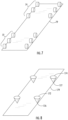
- the holddown devices 72 and 74 are rollers that extend across the width of the foil 22. As shown in FIG. 6 , according to an alternative embodiment, the holddown devices 72 and 74 are each comprised of a pair of short rollers or wheels that are spaced apart from each other.
- the holddown devices 72 and 74 can be a series of rollers or wheels. It should be appreciated that the additional series of contact points can control the tension of the foil 22.
- the alternative embodiment includes holddown devices 172 and 174.
- the holddown devices 172 and 174 have fixed contact locations 176 and 177 respectively.
- the fixed contact locations can be configured with minimal areas such as the points of cones as shown in FIG. 8 .
- the holddown devices can include a combination of geometric configurations.
- FIGS. 10 and 11 show an alternative embodiment of the disclosed technology in which the holddown devices are provided in pairs having variable spacing.
- each of the holddown devices 72, 74 includes a pair of rollers 191, 192 that are spaced apart a first distance D.
- Each pair of rollers 191, 192 is configured to move between a first position in which they are spaced apart a first distance D and a second position in which they are spaced apart a second distance D'.
- the second distance D prime is greater than the first distance D.
- Lateral movement at least one of the rollers 191, 192 of a pair of rollers can be used to achieve the spacing differences. It should be appreciated that lateral movement of at least one roller can be used to achieve this result.
- lateral movement of the holddown device 170 or the holddown device 172 can be used to change the associated approach angle ⁇ defined by the holddown device as described above.
- Variation of the approach angle ⁇ can be used to control the rate of peeling. In this regard, a slower rate of peeling might be preferable just prior to release from the part 65 of remaining structure 79 or at the beginning of the peeling process.
- the holddown devices 272 and 274 are attached to a spring loaded support 290. It should be appreciaterfd that they can also be attached to a force measuring device 292 as indicated in FIG. 12 . It should also be appreciated that such a measuring device 292 can be utilized in a closed loop control system with an actuator configured nto vary the force applied by the holddown device 70 to the remaining structure 79.
- the actuator can be configured to vary the spring force applied by spring 290.
- the force measured can be that applied by the stage 14 as the stage 14 moves up during the separation process, force applied by at least one of the driven rollers 20 and 21, and a combination thereof.
- a first force measured between the driven roller 20 and the part 65 and a second force measured between the driven roller 21 and the part 65 are independent of each other.
- tension on the film 22 is applied by one of the driven rollers 20 and 21 extends between the fixed location of the film 22 at the part 65 to which it is attached and the associated driven roller 20 and 21.
- the tension between the driven rollers 20 and 21 are not independent and should be the sum of the tension applied the by the driven rollers 20 and 21 and the intervening drive and drive forces positioned between the driven rollers 20 and 21.
- the first driven roller 20 can be utilized to affect the peel rate by controlling the tension between the part 65 and the first driven roller 20.
- the second driven roller 21 can be utilized to affect the peel rate by controlling the tension between the part 65 and the second driven roller 21.
- the first driven roller 20 will be operated to apply force to the film 22 that is opposite in direction to the normal direction of travel of the film 22.
- the second driven roller 21 will be operated to apply force to the film 22 that is in the same direction as the normal direction of travel of the film 22. As illustrated in FIG. 1 , the normal direction of travel is from the first driven roller 20 toward the second driven roller 21.
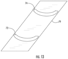
- the holddown devices 70 can also be a variety of shapes and configurations such as bowed rollers.
- the build surface 26 may be cleaned or otherwise rejuvenated and prepared for re-use. For example, advancing the foil 22 provides a clean surface within the build zone 28. As the foil 22 advances, the material depositor 30 would be used to apply resin R to the build surface 26 to ready it for curing again.
- the component 65 and/or the stage 14 may be cleaned to remove uncured resin R, debris, or contaminants between curing cycles.
- the cleaning process may be used for the purpose of removing resin R that did not cure or resin R that did not cure enough to gel during the selective curing step described above.
- cleaning could be done by contacting the component 65 and/or the stage 14 with a cleaning fluid such as a liquid detergent or solvent.
- This cycle of preparing the build surface 26, incrementing a layer, selectively curing, separating the component 65 from the build surface 26, imaging the resin R and cleaning the component 65 and/or stage 14 would be repeated as necessary until the entire component 65 is complete.
- a scanned beam apparatus may be used in combination with a projector.
- a scanned beam apparatus may be used to apply radiant energy (in addition to that applied by the projector) by scanning one or multiple beams over the surface of the uncured resin R. This may be concurrent or sequential with the use of the projector.
- Either curing method projects or scanned results in a component 65 in which the filler (if used) is held in a solid shape by the cured resin R.
- This component may be usable as an end product for some conditions. Subsequent to the curing step, the component 65 may be removed from the stage 14.
- the component 65 may be treated to a conventional sintering process to burn out the resin R and to consolidate the ceramic or metallic particles.
- a known infiltration process may be carried out during or after the sintering process, in order to fill voids in the component with a material having a lower melting temperature than the filler. The infiltration process improves component physical properties.
Landscapes
- Chemical & Material Sciences (AREA)
- Engineering & Computer Science (AREA)
- Materials Engineering (AREA)
- Manufacturing & Machinery (AREA)
- Physics & Mathematics (AREA)
- Optics & Photonics (AREA)
- Mechanical Engineering (AREA)
- Health & Medical Sciences (AREA)
- Toxicology (AREA)
- Battery Electrode And Active Subsutance (AREA)
Applications Claiming Priority (2)
| Application Number | Priority Date | Filing Date | Title |
|---|---|---|---|
| US16/542,522 US11446860B2 (en) | 2019-08-16 | 2019-08-16 | Method and apparatus for separation of cured resin layer from resin support in additive manufacturing |
| EP20188745.2A EP3808540B1 (de) | 2019-08-16 | 2020-07-30 | Vorrichtung zur trennung einer gehärteten harzschicht von einem harzträger bei der generativen fertigung |
Related Parent Applications (2)
| Application Number | Title | Priority Date | Filing Date |
|---|---|---|---|
| EP20188745.2A Division-Into EP3808540B1 (de) | 2019-08-16 | 2020-07-30 | Vorrichtung zur trennung einer gehärteten harzschicht von einem harzträger bei der generativen fertigung |
| EP20188745.2A Division EP3808540B1 (de) | 2019-08-16 | 2020-07-30 | Vorrichtung zur trennung einer gehärteten harzschicht von einem harzträger bei der generativen fertigung |
Publications (2)
| Publication Number | Publication Date |
|---|---|
| EP4378665A2 true EP4378665A2 (de) | 2024-06-05 |
| EP4378665A3 EP4378665A3 (de) | 2024-08-21 |
Family
ID=71894745
Family Applications (2)
| Application Number | Title | Priority Date | Filing Date |
|---|---|---|---|
| EP24164879.9A Pending EP4378665A3 (de) | 2019-08-16 | 2020-07-30 | Vorrichtung zur trennung einer gehärteten harzschicht von einem harzträger in der generativen fertigung |
| EP20188745.2A Active EP3808540B1 (de) | 2019-08-16 | 2020-07-30 | Vorrichtung zur trennung einer gehärteten harzschicht von einem harzträger bei der generativen fertigung |
Family Applications After (1)
| Application Number | Title | Priority Date | Filing Date |
|---|---|---|---|
| EP20188745.2A Active EP3808540B1 (de) | 2019-08-16 | 2020-07-30 | Vorrichtung zur trennung einer gehärteten harzschicht von einem harzträger bei der generativen fertigung |
Country Status (3)
| Country | Link |
|---|---|
| US (1) | US11446860B2 (de) |
| EP (2) | EP4378665A3 (de) |
| CN (1) | CN112388971A (de) |
Families Citing this family (18)
| Publication number | Priority date | Publication date | Assignee | Title |
|---|---|---|---|---|
| WO2021195267A1 (en) | 2020-03-25 | 2021-09-30 | Opt Industries, Inc. | Systems, methods and file format for 3d printing of microstructures |
| US11707883B2 (en) | 2020-11-20 | 2023-07-25 | General Electric Company | Foil interaction device for additive manufacturing |
| US11865780B2 (en) | 2021-02-26 | 2024-01-09 | General Electric Company | Accumalator assembly for additive manufacturing |
| US12589549B2 (en) | 2021-04-27 | 2026-03-31 | General Electric Company | Systems and methods for additive manufacturing |
| US11951679B2 (en) | 2021-06-16 | 2024-04-09 | General Electric Company | Additive manufacturing system |
| EP4105002A1 (de) * | 2021-06-16 | 2022-12-21 | General Electric Company | Schälvorrichtung für generative fertigung |
| US11731367B2 (en) * | 2021-06-23 | 2023-08-22 | General Electric Company | Drive system for additive manufacturing |
| US11958249B2 (en) | 2021-06-24 | 2024-04-16 | General Electric Company | Reclamation system for additive manufacturing |
| US11958250B2 (en) | 2021-06-24 | 2024-04-16 | General Electric Company | Reclamation system for additive manufacturing |
| US11826950B2 (en) | 2021-07-09 | 2023-11-28 | General Electric Company | Resin management system for additive manufacturing |
| US12370741B2 (en) | 2021-08-13 | 2025-07-29 | General Electric Company | Material deposition assembly for additive manufacturing |
| US12296535B2 (en) * | 2021-08-24 | 2025-05-13 | General Electric Company | Attachment structure for additive manufacturing |
| US11813799B2 (en) | 2021-09-01 | 2023-11-14 | General Electric Company | Control systems and methods for additive manufacturing |
| EP4249216A1 (de) | 2022-03-23 | 2023-09-27 | General Electric Company | Systeme und verfahren zur generativen fertigung |
| US20240033992A1 (en) * | 2022-07-28 | 2024-02-01 | General Electric Company | Systems and methods for additive manufacturing |
| US20240033993A1 (en) * | 2022-07-28 | 2024-02-01 | General Electric Company | Systems and methods for additive manufacturing |
| US20240059022A1 (en) * | 2022-08-18 | 2024-02-22 | General Electric Company | Systems and methods for additive manufacturing using pixel shifting |
| US12403654B2 (en) | 2022-09-30 | 2025-09-02 | General Electric Company | Systems and methods for additive manufacturing |
Family Cites Families (43)
| Publication number | Priority date | Publication date | Assignee | Title |
|---|---|---|---|---|
| US4752498A (en) | 1987-03-02 | 1988-06-21 | Fudim Efrem V | Method and apparatus for production of three-dimensional objects by photosolidification |
| JPH03244528A (ja) | 1989-09-28 | 1991-10-31 | Three D Syst Inc | 実質的に平担な立体平版加工面の形成装置および方法 |
| US5096530A (en) | 1990-06-28 | 1992-03-17 | 3D Systems, Inc. | Resin film recoating method and apparatus |
| JP2580472B2 (ja) | 1993-07-07 | 1997-02-12 | 本州製紙株式会社 | 段ボール初期接着強度測定方法及びそれに用いる測定装置 |
| JP2706611B2 (ja) | 1993-10-14 | 1998-01-28 | 帝人製機株式会社 | 光造形方法および光造形装置 |
| DE20106887U1 (de) | 2001-04-20 | 2001-09-06 | Envision Technologies GmbH, 45768 Marl | Vorrichtung zum Herstellen eines dreidimensionalen Objekts |
| DE10119817A1 (de) | 2001-04-23 | 2002-10-24 | Envision Technologies Gmbh | Vorrichtung und Verfahren für die zerstörungsfreie Trennung ausgehärteter Materialschichten von einer planen Bauebene |
| DE102004022606A1 (de) | 2004-05-07 | 2005-12-15 | Envisiontec Gmbh | Verfahren zur Herstellung eines dreidimensionalen Objekts mit verbesserter Trennung ausgehärteter Materialschichten von einer Bauebene |
| US20060263530A1 (en) | 2005-05-19 | 2006-11-23 | General Electric Company | Process for making non-continuous articles with microstructures |
| JP5080148B2 (ja) | 2007-06-28 | 2012-11-21 | リコーマイクロエレクトロニクス株式会社 | 印刷装置および印刷方法、印刷マスク、並びに印刷マスクの製造方法 |
| EP2011631B1 (de) | 2007-07-04 | 2012-04-18 | Envisiontec GmbH | Verfahren und Vorrichtung zum Herstellen eines dreidimensionalen Objekts |
| DK2052693T4 (da) | 2007-10-26 | 2021-03-15 | Envisiontec Gmbh | Proces og fri-formfabrikationssystem til at fremstille en tredimensionel genstand |
| US8741203B2 (en) | 2008-10-20 | 2014-06-03 | Ivoclar Vivadent Ag | Device and method for processing light-polymerizable material for building up an object in layers |
| WO2010045950A1 (de) | 2008-10-20 | 2010-04-29 | Ivoclar Vivadent Ag | Vorrichtung und verfahren zur verarbeitung von lichtpolymerisierbarem material zum schichtweisen aufbau von formkörpern |
| GB0819935D0 (en) * | 2008-10-30 | 2008-12-10 | Mtt Technologies Ltd | Additive manufacturing apparatus and method |
| US8777602B2 (en) | 2008-12-22 | 2014-07-15 | Nederlandse Organisatie Voor Tobgepast-Natuurwetenschappelijk Onderzoek TNO | Method and apparatus for layerwise production of a 3D object |
| US8326024B2 (en) | 2009-04-14 | 2012-12-04 | Global Filtration Systems | Method of reducing the force required to separate a solidified object from a substrate |
| US8372330B2 (en) | 2009-10-19 | 2013-02-12 | Global Filtration Systems | Resin solidification substrate and assembly |
| IT1397457B1 (it) | 2010-01-12 | 2013-01-10 | Dws Srl | Piastra di modellazione per una macchina stereolitografica, macchina stereolitografica impiegante tale piastra di modellazione e utensile per la pulizia di tale piastra di modellazione. |
| US20130241113A1 (en) | 2010-10-22 | 2013-09-19 | Dsm Ip Assets B.V. | Additive fabrication apparatus and method of layerwise production of a tangible object |
| ES2449291T3 (es) | 2010-11-01 | 2014-03-19 | Dsm Ip Assets B.V. | Aparato y método de fabricación por adición que comprende un sistema de guía de lámina de movimiento alternativo |
| IT1403482B1 (it) | 2011-01-18 | 2013-10-17 | Dws Srl | Metodo per la produzione di un oggetto tridimensionale e macchina stereolitografica impiegante tale metodo |
| ES2934103T3 (es) | 2011-01-31 | 2023-02-16 | Global Filtration Systems Dba Gulf Filtration Systems Inc | Aparato para fabricar objetos tridimensionales a partir de múltiples materiales solidificables |
| JP5989106B2 (ja) | 2011-06-15 | 2016-09-07 | ディーエスエム アイピー アセッツ ビー.ブイ. | 基材ベース積層造形法および装置 |
| CN103619566B (zh) | 2011-06-22 | 2017-04-05 | 帝斯曼知识产权资产管理有限公司 | 用于箔从材料层分离的设备和方法 |
| US9636873B2 (en) | 2012-05-03 | 2017-05-02 | B9Creations, LLC | Solid image apparatus with improved part separation from the image plate |
| BR112015012419B1 (pt) * | 2012-12-13 | 2021-04-06 | Canon Kabushiki Kaisha | Método para fabricar corpo estrutural e aparelho de fabricação para o mesmo |
| WO2014126834A2 (en) | 2013-02-12 | 2014-08-21 | Eipi Systems, Inc. | Method and apparatus for three-dimensional fabrication with feed through carrier |
| NL2012087C2 (en) | 2014-01-15 | 2015-07-16 | Admatec Europ B V | Additive manufacturing system for manufacturing a three dimensional object. |
| US11104117B2 (en) | 2014-02-20 | 2021-08-31 | Global Filtration Systems | Apparatus and method for forming three-dimensional objects using a tilting solidification substrate |
| US10144205B2 (en) | 2014-02-20 | 2018-12-04 | Global Filtration Systems | Apparatus and method for forming three-dimensional objects using a tilting solidification substrate |
| US10011076B2 (en) | 2014-02-20 | 2018-07-03 | Global Filtration Systems | Apparatus and method for forming three-dimensional objects using a tilting solidification substrate |
| US10086535B2 (en) | 2014-04-02 | 2018-10-02 | B9Creations, LLC | Additive manufacturing device with sliding plate and peeling film |
| TWI594873B (zh) | 2014-05-12 | 2017-08-11 | 三緯國際立體列印科技股份有限公司 | 偵測成型材特性的方法與立體列印裝置 |
| US9895843B2 (en) | 2014-07-17 | 2018-02-20 | Formlabs, Inc. | Systems and methods for an improved peel operation during additive fabrication |
| US11390062B2 (en) | 2014-08-12 | 2022-07-19 | Carbon, Inc. | Three-dimensional printing with supported build plates |
| US10201963B2 (en) | 2014-08-18 | 2019-02-12 | Formlabs, Inc. | Systems and methods for an improved peel operation during additive fabrication |
| US10213966B2 (en) | 2014-08-20 | 2019-02-26 | Formlabs, Inc. | Techniques for applying a peel operation during additive fabrication and related systems and methods |
| EP3322572B1 (de) | 2015-07-15 | 2023-06-21 | Admatec Europe B.V. | Vorrichtung zur generativen fertigung zur herstellung eines dreidimensionalen objekts |
| US10792868B2 (en) | 2015-09-09 | 2020-10-06 | Carbon, Inc. | Method and apparatus for three-dimensional fabrication |
| US20170291355A1 (en) * | 2016-04-12 | 2017-10-12 | Jing Zhang | Apparatus for 3D printing |
| CN109952189A (zh) * | 2016-11-17 | 2019-06-28 | 奥博泰克有限公司 | 混合式多材料3d打印 |
| US10759114B2 (en) * | 2017-12-29 | 2020-09-01 | Continuous Composites Inc. | System and print head for continuously manufacturing composite structure |
-
2019
- 2019-08-16 US US16/542,522 patent/US11446860B2/en active Active
-
2020
- 2020-07-30 EP EP24164879.9A patent/EP4378665A3/de active Pending
- 2020-07-30 EP EP20188745.2A patent/EP3808540B1/de active Active
- 2020-08-17 CN CN202010824235.8A patent/CN112388971A/zh active Pending
Also Published As
| Publication number | Publication date |
|---|---|
| CN112388971A (zh) | 2021-02-23 |
| EP3808540B1 (de) | 2024-04-24 |
| US11446860B2 (en) | 2022-09-20 |
| EP4378665A3 (de) | 2024-08-21 |
| US20210046695A1 (en) | 2021-02-18 |
| EP3808540A1 (de) | 2021-04-21 |
Similar Documents
| Publication | Publication Date | Title |
|---|---|---|
| EP3808540B1 (de) | Vorrichtung zur trennung einer gehärteten harzschicht von einem harzträger bei der generativen fertigung | |
| US11707888B2 (en) | Method and apparatus for additive manufacturing with shared components | |
| US11945157B2 (en) | Multi-material additive manufacturing apparatus and method | |
| US11590691B2 (en) | Plate-based additive manufacturing apparatus and method | |
| EP3917758B1 (de) | Verfahren und vorrichtung zur prozessüberwachung bei der generativen fertigung | |
| US10821668B2 (en) | Method for producing a component layer-by- layer | |
| US20190126536A1 (en) | Cartridge vat-based additive manufacturing apparatus and method | |
| US20190126535A1 (en) | Cartridge plate-based additive manufacturing apparatus and method | |
| EP3680089B1 (de) | Verfahren zur generativen fertigung für funktionell gradiertes material | |
| US12521942B2 (en) | Reclamation system for additive manufacturing |
Legal Events
| Date | Code | Title | Description |
|---|---|---|---|
| PUAI | Public reference made under article 153(3) epc to a published international application that has entered the european phase |
Free format text: ORIGINAL CODE: 0009012 |
|
| STAA | Information on the status of an ep patent application or granted ep patent |
Free format text: STATUS: THE APPLICATION HAS BEEN PUBLISHED |
|
| AC | Divisional application: reference to earlier application |
Ref document number: 3808540 Country of ref document: EP Kind code of ref document: P |
|
| AK | Designated contracting states |
Kind code of ref document: A2 Designated state(s): AL AT BE BG CH CY CZ DE DK EE ES FI FR GB GR HR HU IE IS IT LI LT LU LV MC MK MT NL NO PL PT RO RS SE SI SK SM TR |
|
| PUAL | Search report despatched |
Free format text: ORIGINAL CODE: 0009013 |
|
| AK | Designated contracting states |
Kind code of ref document: A3 Designated state(s): AL AT BE BG CH CY CZ DE DK EE ES FI FR GB GR HR HU IE IS IT LI LT LU LV MC MK MT NL NO PL PT RO RS SE SI SK SM TR |
|
| RIC1 | Information provided on ipc code assigned before grant |
Ipc: B29C 64/245 20170101ALI20240715BHEP Ipc: B33Y 30/00 20150101ALI20240715BHEP Ipc: B29C 64/286 20170101ALI20240715BHEP Ipc: B29C 64/223 20170101ALI20240715BHEP Ipc: B29C 64/129 20170101AFI20240715BHEP |
|
| STAA | Information on the status of an ep patent application or granted ep patent |
Free format text: STATUS: REQUEST FOR EXAMINATION WAS MADE |
|
| 17P | Request for examination filed |
Effective date: 20250131 |