EP4378024B1 - Method for producing an individual battery cell - Google Patents
Method for producing an individual battery cell Download PDFInfo
- Publication number
- EP4378024B1 EP4378024B1 EP23738639.6A EP23738639A EP4378024B1 EP 4378024 B1 EP4378024 B1 EP 4378024B1 EP 23738639 A EP23738639 A EP 23738639A EP 4378024 B1 EP4378024 B1 EP 4378024B1
- Authority
- EP
- European Patent Office
- Prior art keywords
- stack
- welded
- welding
- cell
- collector tabs
- Prior art date
- Legal status (The legal status is an assumption and is not a legal conclusion. Google has not performed a legal analysis and makes no representation as to the accuracy of the status listed.)
- Active
Links
Images
Classifications
-
- H—ELECTRICITY
- H01—ELECTRIC ELEMENTS
- H01M—PROCESSES OR MEANS, e.g. BATTERIES, FOR THE DIRECT CONVERSION OF CHEMICAL ENERGY INTO ELECTRICAL ENERGY
- H01M50/00—Constructional details or processes of manufacture of the non-active parts of electrochemical cells other than fuel cells, e.g. hybrid cells
- H01M50/50—Current conducting connections for cells or batteries
- H01M50/531—Electrode connections inside a battery casing
- H01M50/536—Electrode connections inside a battery casing characterised by the method of fixing the leads to the electrodes, e.g. by welding
-
- H—ELECTRICITY
- H01—ELECTRIC ELEMENTS
- H01M—PROCESSES OR MEANS, e.g. BATTERIES, FOR THE DIRECT CONVERSION OF CHEMICAL ENERGY INTO ELECTRICAL ENERGY
- H01M50/00—Constructional details or processes of manufacture of the non-active parts of electrochemical cells other than fuel cells, e.g. hybrid cells
- H01M50/10—Primary casings; Jackets or wrappings
- H01M50/147—Lids or covers
- H01M50/166—Lids or covers characterised by the methods of assembling casings with lids
- H01M50/169—Lids or covers characterised by the methods of assembling casings with lids by welding, brazing or soldering
-
- H—ELECTRICITY
- H01—ELECTRIC ELEMENTS
- H01M—PROCESSES OR MEANS, e.g. BATTERIES, FOR THE DIRECT CONVERSION OF CHEMICAL ENERGY INTO ELECTRICAL ENERGY
- H01M50/00—Constructional details or processes of manufacture of the non-active parts of electrochemical cells other than fuel cells, e.g. hybrid cells
- H01M50/50—Current conducting connections for cells or batteries
- H01M50/531—Electrode connections inside a battery casing
- H01M50/533—Electrode connections inside a battery casing characterised by the shape of the leads or tabs
-
- H—ELECTRICITY
- H01—ELECTRIC ELEMENTS
- H01M—PROCESSES OR MEANS, e.g. BATTERIES, FOR THE DIRECT CONVERSION OF CHEMICAL ENERGY INTO ELECTRICAL ENERGY
- H01M50/00—Constructional details or processes of manufacture of the non-active parts of electrochemical cells other than fuel cells, e.g. hybrid cells
- H01M50/50—Current conducting connections for cells or batteries
- H01M50/531—Electrode connections inside a battery casing
- H01M50/538—Connection of several leads or tabs of wound or folded electrode stacks
-
- H—ELECTRICITY
- H01—ELECTRIC ELEMENTS
- H01M—PROCESSES OR MEANS, e.g. BATTERIES, FOR THE DIRECT CONVERSION OF CHEMICAL ENERGY INTO ELECTRICAL ENERGY
- H01M50/00—Constructional details or processes of manufacture of the non-active parts of electrochemical cells other than fuel cells, e.g. hybrid cells
- H01M50/50—Current conducting connections for cells or batteries
- H01M50/531—Electrode connections inside a battery casing
- H01M50/54—Connection of several leads or tabs of plate-like electrode stacks, e.g. electrode pole straps or bridges
-
- H—ELECTRICITY
- H01—ELECTRIC ELEMENTS
- H01M—PROCESSES OR MEANS, e.g. BATTERIES, FOR THE DIRECT CONVERSION OF CHEMICAL ENERGY INTO ELECTRICAL ENERGY
- H01M50/00—Constructional details or processes of manufacture of the non-active parts of electrochemical cells other than fuel cells, e.g. hybrid cells
- H01M50/50—Current conducting connections for cells or batteries
- H01M50/543—Terminals
- H01M50/564—Terminals characterised by their manufacturing process
- H01M50/566—Terminals characterised by their manufacturing process by welding, soldering or brazing
-
- B—PERFORMING OPERATIONS; TRANSPORTING
- B23—MACHINE TOOLS; METAL-WORKING NOT OTHERWISE PROVIDED FOR
- B23K—SOLDERING OR UNSOLDERING; WELDING; CLADDING OR PLATING BY SOLDERING OR WELDING; CUTTING BY APPLYING HEAT LOCALLY, e.g. FLAME CUTTING; WORKING BY LASER BEAM
- B23K20/00—Non-electric welding by applying impact or other pressure, with or without the application of heat, e.g. cladding or plating
- B23K20/10—Non-electric welding by applying impact or other pressure, with or without the application of heat, e.g. cladding or plating making use of vibrations, e.g. ultrasonic welding
-
- B—PERFORMING OPERATIONS; TRANSPORTING
- B23—MACHINE TOOLS; METAL-WORKING NOT OTHERWISE PROVIDED FOR
- B23K—SOLDERING OR UNSOLDERING; WELDING; CLADDING OR PLATING BY SOLDERING OR WELDING; CUTTING BY APPLYING HEAT LOCALLY, e.g. FLAME CUTTING; WORKING BY LASER BEAM
- B23K2101/00—Articles made by soldering, welding or cutting
- B23K2101/36—Electric or electronic devices
-
- Y—GENERAL TAGGING OF NEW TECHNOLOGICAL DEVELOPMENTS; GENERAL TAGGING OF CROSS-SECTIONAL TECHNOLOGIES SPANNING OVER SEVERAL SECTIONS OF THE IPC; TECHNICAL SUBJECTS COVERED BY FORMER USPC CROSS-REFERENCE ART COLLECTIONS [XRACs] AND DIGESTS
- Y02—TECHNOLOGIES OR APPLICATIONS FOR MITIGATION OR ADAPTATION AGAINST CLIMATE CHANGE
- Y02E—REDUCTION OF GREENHOUSE GAS [GHG] EMISSIONS, RELATED TO ENERGY GENERATION, TRANSMISSION OR DISTRIBUTION
- Y02E60/00—Enabling technologies; Technologies with a potential or indirect contribution to GHG emissions mitigation
- Y02E60/10—Energy storage using batteries
-
- Y—GENERAL TAGGING OF NEW TECHNOLOGICAL DEVELOPMENTS; GENERAL TAGGING OF CROSS-SECTIONAL TECHNOLOGIES SPANNING OVER SEVERAL SECTIONS OF THE IPC; TECHNICAL SUBJECTS COVERED BY FORMER USPC CROSS-REFERENCE ART COLLECTIONS [XRACs] AND DIGESTS
- Y02—TECHNOLOGIES OR APPLICATIONS FOR MITIGATION OR ADAPTATION AGAINST CLIMATE CHANGE
- Y02P—CLIMATE CHANGE MITIGATION TECHNOLOGIES IN THE PRODUCTION OR PROCESSING OF GOODS
- Y02P70/00—Climate change mitigation technologies in the production process for final industrial or consumer products
- Y02P70/50—Manufacturing or production processes characterised by the final manufactured product
Definitions
- the invention relates to a method for manufacturing a single battery cell according to the type defined in the preamble of claim 1
- Individual battery cells for example in lithium-ion technology, are fundamentally known from the state of the art. They essentially consist of a housing and electrochemically active materials arranged in this housing. Typically, this is a stack or possibly a coil of cathodes, anodes and separators, which are placed in the housing and soaked with electrolyte. Finally, the housing is closed.
- the electrodes are typically contacted via conductor tabs that protrude above the stack or coil, with the conductor tabs of the cathode typically protruding on one side and the conductor tabs of the anode on the other.
- the conductor tabs of the anodes can be welded together and those of the cathode pressed against a metallically conductive housing or something similar. Of course, this can also be done the other way around, or both electrodes can be welded accordingly.
- an electrode arrangement for a battery cell is known.
- the conductor tabs of the individual electrodes are wound together with a conductor of the individual battery cell and are connected, e.g. welded, to an anode conductor or cathode conductor for all corresponding electrodes within the individual battery cell. This can then be led out of a housing in an insulated manner, for example.
- the WO 2010/030606 A2 describes an electrochemical cell with at least one electrode.
- the end of each individual electrode foil that protrudes above the active material is wound up to facilitate contacting of all the same-polar electrodes of the individual battery cell.
- the object of the present invention is to provide a method for manufacturing a battery cell which further simplifies the structure known from the general prior art and yet ensures safe and reliable electrical contacting of the conductor lugs.
- the method according to the invention provides that the conductor lugs are welded, as is known from the prior art. According to the invention, they are compacted and first tacked on their side facing the stack or coil by this welding, which according to a very advantageous embodiment can be designed as ultrasonic welding, in order to prevent their position within the stack or coil is changed and individual electrodes or separators are pulled out of the stack or coil during production.
- the conductor lugs stapled in this way using ultrasonic welding are then gripped by a welding electrode at the end facing away from the stack or coil and wound around this welding electrode in the direction of the stack or coil. Finally, a cell cover of the individual battery cell is welded to the wound conductor lugs.
- the conductor lugs are wound up in the direction of the stack on a welding electrode located inside this coil.
- the structure can then be supplemented directly by the cell cover, i.e. without an intermediate current collector, by welding this cell cover to the rolled-up or wound conductor foils. These then form a coil welded to the cell cover, resulting in a mechanically stable structure that only partially transfers the heat generated during welding to the stack or coil. In particular, a large part of the heat is dissipated by the welding electrode.
- the conductor foils are gripped by means of a groove in the welding electrode.
- a groove can be provided, for example, in a square or round welding electrode. This is positioned on the stack of stapled conductor tabs in such a way that the end facing away from the stack or coil, which was compacted during or after stapling, comes to rest in this groove. By turning the welding electrode, this compacted stack of conductor foils is then wound around this welding electrode.
- the welding electrode is then removed from the wound conductor foils after the wound conductor foils have been welded onto the cell cover, so that a hollow roll remains which is very stable in itself due to the multi-layer structure, the individual layers of which are welded to one another and to the cell cover in a line along the central axis of the welding electrode on the side facing the cell cover.
- This very stable structure consisting of cell cover and stack or coil can then be handled easily and efficiently and inserted into a housing, after which the cell cover is welded to the housing, preferably by laser welding.
- the wound arrester foils can also be welded onto the cell cover or the cell cover onto the wound arrester foils using ultrasonic welding. Only the welding of the cover onto the housing can be implemented more efficiently, preferably using laser welding.
- Another very advantageous embodiment of the method for producing the individual battery cell according to the invention provides that the conductor foils are stapled in the stacking direction or transversely to the winding direction at approximately the middle height.
- the conductor foils are therefore not collected on one side of the stack and compacted and welded there, as is largely common today, but rather they are brought together in the middle in order to staple them together as close as possible to the cell stack, with the individual conductor foils having to travel as little distance as possible to the weld seam.
- a single battery cell produced according to the method according to the invention now provides a stack or coil of cathodes, anodes and separators, which is arranged in a cell housing closed with a cell cover.
- the conductor lugs of at least one of the electrodes protrude beyond the stack or coil and are rolled up in this area and welded to the cell cover.
- the cell cover can in turn be welded to the housing.
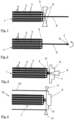
- a section of a stack 1 can be seen.
- This stack 1 consists of different electrodes 2, 3, i.e. the anodes and the cathodes. Separators 4 are arranged between them.
- the cathodes are supported on an aluminum foil, which is shown here with a thick solid black line.
- the ends of these cathodes 2 protrude laterally over the stack 1 as conductor lugs 5 transversely to the stacking direction S. They are combined in this area, whereby only five individual cathodes 2 are shown in the figure in order to simplify the illustration accordingly.
- the conductor lugs 5 are combined in the middle in relation to the height of the stack 1 in the stacking direction S and are compacted in the area designated 5'.
- the end of the compacted conductor lugs 5' facing away from the stack 1 is now gripped by a welding electrode 7, which is designed, for example, as a rod-shaped electrode with a groove 8, by inserting the compacted conductor lugs 5' into this groove.
- the welding electrode 7 is then inserted according to the arrow in Figure 2 wound in the direction of the stack 1, so that a roll 5" is created from several spiral layers of the compacted conductor lugs 5'.
- This roll 5" with the welding electrode 7 arranged therein is then brought into contact with a cell cover 9 and welded to it through the material of this cell cover 9.
- This process can also be carried out as ultrasonic welding, which is why the symbolic representation of the welding is again provided with the reference number 6.
- the wound conductor lugs, which are designated here with 5" after winding into the roll form a very compact Structure which can be easily welded to the cell cover 9 efficiently and reliably.
- the welding electrode 7 is then pulled out sideways and a very robust structure is created from stack 1 and cell cover 9, which can then be placed, for example, in a housing already filled with electrolyte or, after soaking the stack 1, in a housing 10 such as that shown in the illustration of the Figure 4 can be seen.
- the structure is also shown purely schematically here, typically the cell stack will of course use more space within the housing.
- the cell cover 9 can then be welded to the housing 10, for example by laser welding, which is indicated here by the two triangles 11.
- the described method and the single battery cell 12 obtainable by this method can be used for both round and prismatic housings 9.
- it is suitable for the electrical contact of a stack 1 with the cell cover and is therefore preferably used for a structure with a prismatic housing 10.
Landscapes
- Chemical & Material Sciences (AREA)
- Chemical Kinetics & Catalysis (AREA)
- Electrochemistry (AREA)
- General Chemical & Material Sciences (AREA)
- Engineering & Computer Science (AREA)
- Manufacturing & Machinery (AREA)
- Connection Of Batteries Or Terminals (AREA)
- Secondary Cells (AREA)
- Sealing Battery Cases Or Jackets (AREA)
Description
Die Erfindung betrifft ein Verfahren zum Fertigen einer Batterieeinzelzelle nach der im Oberbegriff von Anspruch 1 näher definierten ArtThe invention relates to a method for manufacturing a single battery cell according to the type defined in the preamble of
Batterieeinzelzellen, beispielsweise in Lithium-Ionen-Technologie sind aus dem Stand der Technik grundlegend bekannt. Sie bestehen im Wesentlichen aus einem Gehäuse und in diesem Gehäuse angeordneten elektrochemisch aktiven Materialien. Typischerweise handelt es sich dabei um einen Stapel oder gegebenenfalls auch einen Wickel von Kathoden, Anoden und Separatoren, welche in das Gehäuse eingebracht und mit Elektrolyt getränkt werden. Abschließend wird das Gehäuse verschlossen.Individual battery cells, for example in lithium-ion technology, are fundamentally known from the state of the art. They essentially consist of a housing and electrochemically active materials arranged in this housing. Typically, this is a stack or possibly a coil of cathodes, anodes and separators, which are placed in the housing and soaked with electrolyte. Finally, the housing is closed.
Die Kontaktierung der Elektroden erfolgt typischerweise über über den Stapel oder Wickel überstehende Ableiterfahnen, wobei typischerweise auf der einen Seite die Ableiterfahnen der Kathode und auf der anderen Seite die Ableiterfahnen der Anode überstehen. Je nach Ausgestaltung des Gehäuses können beispielsweise die Ableiterfahnen der Anoden miteinander verschweißt werden und die der Kathode gegen ein metallisch leitendes Gehäuse gepresst werden oder Ähnliches. Selbstverständlich lässt sich dies auch andersherum realisieren oder es lassen sich beide Elektroden entsprechend verschweißen.The electrodes are typically contacted via conductor tabs that protrude above the stack or coil, with the conductor tabs of the cathode typically protruding on one side and the conductor tabs of the anode on the other. Depending on the design of the housing, the conductor tabs of the anodes can be welded together and those of the cathode pressed against a metallically conductive housing or something similar. Of course, this can also be done the other way around, or both electrodes can be welded accordingly.
Aus dem allgemeinen Stand der Technik ist es dabei bekannt, dass beim Verschweißen die einzelnen überstehenden Ableiterfahnen mit einem Stromsammler verschweißt werden, welcher dann mit einem Zelldeckel verschweißt wird, beispielsweise vor dem Verschließen der Batterieeinzelzelle, bei welchem der Zelldeckel insbesondere mit dem Gehäuse verschweißt werden kann. Dies ist vergleichsweise aufwändig, benötigt mehrere Schweißnähte und vergleichsweise viel Bauraum durch den zusätzlichen Stromsammler in der Batterieeinzelzelle. Jede Schweißnaht belastet dabei die Elektrochemie der Zelle thermisch, was ein Nachteil ist. Je mehr Material dabei aufgeschmolzen werden muss, desto kritischer kann dies sein.It is known from the general state of the art that during welding the individual protruding conductor lugs are welded to a current collector, which is then welded to a cell cover, for example before closing the individual battery cell, where the cell cover can be welded to the housing in particular. This is comparatively complex, requires several weld seams and a comparatively large amount of installation space due to the additional current collector in the individual battery cell. Each weld seam puts thermal stress on the cell's electrochemistry, which is a disadvantage. The more material that has to be melted, the more critical this can be.
Aus der
Aus der
Die
Die Aufgabe der hier vorliegenden Erfindung besteht nun darin, ein Verfahren zum Fertigen einer Batteriezelle anzugeben, welches den aus dem allgemeinen Stand der Technik bekannten Aufbau weiter vereinfacht und dennoch eine sichere und zuverlässige elektrische Kontaktierung der Ableiterfahnen gewährleistet.The object of the present invention is to provide a method for manufacturing a battery cell which further simplifies the structure known from the general prior art and yet ensures safe and reliable electrical contacting of the conductor lugs.
Erfindungsgemäß wird diese Aufgabe durch das Verfahren mit den Merkmalen im Anspruch 1, und hier insbesondere im kennzeichnenden Teil des Anspruchs 1 gelöst. Vorteilhafte Ausgestaltungen und Weiterbildungen ergeben sich aus den hiervon abhängigen Unteransprüchen.According to the invention, this object is achieved by the method having the features in
Das erfindungsgemäße Verfahren sieht es vor, dass die Ableiterfahnen, so wie es aus dem Stand der Technik bekannt ist, verschweißt werden. Erfindungsgemäß werden sie dazu kompaktiert und auf ihrer dem Stapel oder Wickel zugewandten Seite durch dieses Verschweißen, welches gemäß einer sehr vorteilhaften Ausgestaltung als Ultraschallschweißen ausgebildet sein kann, zuerst geheftet, um zu verhindern, dass sich ihre Position innerhalb des Stapels oder Wickels verändert und einzelne Elektroden oder Separatoren bei der Herstellung aus dem Stapel oder Wickel gezogen werden. Die so über das Ultraschallschweißen gehefteten Ableiterfahnen werden dann an ihrem dem Stapel oder Wickel abgewandten Ende von einer Schweißelektrode gegriffen und in Richtung des Stapels oder Wickels um diese Schweißelektrode aufgewickelt. Abschließend wird dann ein Zelldeckel der Batterieeinzelzelle mit den aufgewickelten Ableiterfahnen verschweißt. Auf die Verwendung eines zusätzlichen Stromsammlers, mit welchem die einzelnen Ableiterfahnen verschweißt sind, wird hier also verzichtet. Anders als im oben genannten Stand der Technik bleiben die gehefteten Ableiterfahnen dabei auch nicht unbearbeitet, da diese dann sehr dünn und anfällig bei mechanischer Belastung sind und sehr schnell einreißen könnten, was die elektrische Leistungsfähigkeit des Aufbaus massiv beeinträchtigen würde.The method according to the invention provides that the conductor lugs are welded, as is known from the prior art. According to the invention, they are compacted and first tacked on their side facing the stack or coil by this welding, which according to a very advantageous embodiment can be designed as ultrasonic welding, in order to prevent their position within the stack or coil is changed and individual electrodes or separators are pulled out of the stack or coil during production. The conductor lugs stapled in this way using ultrasonic welding are then gripped by a welding electrode at the end facing away from the stack or coil and wound around this welding electrode in the direction of the stack or coil. Finally, a cell cover of the individual battery cell is welded to the wound conductor lugs. The use of an additional current collector to which the individual conductor lugs are welded is therefore dispensed with here. Unlike in the above-mentioned prior art, the stapled conductor lugs are not left unprocessed, as they are then very thin and susceptible to mechanical stress and could tear very quickly, which would massively impair the electrical performance of the structure.
Vielmehr werden bei dem erfindungsgemäßen Verfahren die Ableiterfahnen in Richtung des Stapels aufgewickelt und zwar auf einer im Inneren dieses Wickels befindlichen Schweißelektrode. Der Aufbau kann dann durch den Zelldeckel direkt, also ohne zwischengeschalteten Stromsammler ergänzt werden, indem dieser Zelldeckel mit den aufgerollten beziehungsweise aufgewickelten Ableiterfolien verschweißt wird. Diese bilden dann einen mit dem Zelldeckel verschweißten Wickel, was einen mechanisch stabilen Aufbau ergibt, welcher die beim Schweißen anfallende Wärme nur teilweise an den Stapel bzw. Wickel weiterleitet. Insbesondere wird ein großer Teil der Wärme durch die Schweißelektrode abgeführt.Rather, in the method according to the invention, the conductor lugs are wound up in the direction of the stack on a welding electrode located inside this coil. The structure can then be supplemented directly by the cell cover, i.e. without an intermediate current collector, by welding this cell cover to the rolled-up or wound conductor foils. These then form a coil welded to the cell cover, resulting in a mechanically stable structure that only partially transfers the heat generated during welding to the stack or coil. In particular, a large part of the heat is dissipated by the welding electrode.
Gemäß einer weiteren sehr günstigen Ausgestaltung des erfindungsgemäßen Verfahrens kann es dabei vorgesehen sein, dass die Ableiterfolien mittels einer Nut in der Schweißelektrode gegriffen werden. Eine solche Nut kann beispielsweise in einer eckigen oder runden Schweißelektrode vorgesehen sein. Diese wird so auf dem Stapel der zusammengehefteten Ableiterfahnen positioniert, dass dessen dem Stapel oder Wickel abgewandtes Ende, welches beim oder nach dem Heften kompaktiert worden ist, in dieser Nut zu liegen kommt. Durch ein Eindrehen der Schweißelektrode wird dieser kompaktierte Stapel der Ableiterfolien nun um diese Schweißelektrode herum aufgewickelt. Gemäß einer weiteren sehr günstigen Ausgestaltung wird die Schweißelektrode dann nach dem Aufschweißen der aufgewickelten Ableiterfolien auf den Zelldeckel aus den aufgewickelten Ableiterfolien entfernt, sodass eine hohle in sich jedoch durch die Mehrlagigkeit sehr stabile Rolle verbleibt, deren einzelne Schichten auf der dem Zelldeckel zugewandten Seite linienförmig entlang der zentralen Achse der Schweißelektrode miteinander und mit dem Zelldeckel verschweißt sind.According to another very favorable embodiment of the method according to the invention, it can be provided that the conductor foils are gripped by means of a groove in the welding electrode. Such a groove can be provided, for example, in a square or round welding electrode. This is positioned on the stack of stapled conductor tabs in such a way that the end facing away from the stack or coil, which was compacted during or after stapling, comes to rest in this groove. By turning the welding electrode, this compacted stack of conductor foils is then wound around this welding electrode. According to another very favorable embodiment, the welding electrode is then removed from the wound conductor foils after the wound conductor foils have been welded onto the cell cover, so that a hollow roll remains which is very stable in itself due to the multi-layer structure, the individual layers of which are welded to one another and to the cell cover in a line along the central axis of the welding electrode on the side facing the cell cover.
Dieser sehr stabile Aufbau aus Zelldeckel und Stapel oder Wickel kann dann einfach und effizient gehandhabt und in ein Gehäuse eingebracht werden, wonach der Zelldeckel vorzugsweise über Laserschweißen, mit dem Gehäuse verschweißt wird.This very stable structure consisting of cell cover and stack or coil can then be handled easily and efficiently and inserted into a housing, after which the cell cover is welded to the housing, preferably by laser welding.
Nicht nur das Heften der Ableiterfolien kann dabei mittels Ultraschallschweißen erfolgen, sondern gemäß einer sehr vorteilhaften Ausgestaltung des erfindungsgemäßen Verfahrens kann auch auf das Aufschweißen der aufgewickelten Ableiterfolien auf den Zelldeckel beziehungsweise des Zelldeckels auf die aufgewickelten Ableiterfolien mittels Ultraschallschweißen erfolgen. Lediglich das Anschweißen des Deckels an dem Gehäuse lässt sich vorzugsweise über Laserschweißen effizienter umsetzen.Not only can the arrester foils be attached using ultrasonic welding, but according to a very advantageous embodiment of the method according to the invention, the wound arrester foils can also be welded onto the cell cover or the cell cover onto the wound arrester foils using ultrasonic welding. Only the welding of the cover onto the housing can be implemented more efficiently, preferably using laser welding.
Eine weitere sehr günstige Ausgestaltung des Verfahrens zum Herstellen der erfindungsgemäßen Batterieeinzelzelle sieht es dabei vor, dass das Heften der Ableiterfolien in Stapelrichtung beziehungsweise quer zur Wickelrichtung in ungefähr mittiger Höhe erfolgt. Die Ableiterfolien werden also nicht, wie es heute weitgehend üblich ist, auf einer Seite des Stapels gesammelt und dort kompaktiert und verschweißt, sondern sie werden mittig zusammengeführt, um sie möglichst nah an dem Zellstapel, mit möglichst wenig Weg der einzelnen Ableiterfolien bis zur Schweißnaht untereinander zu heften.Another very advantageous embodiment of the method for producing the individual battery cell according to the invention provides that the conductor foils are stapled in the stacking direction or transversely to the winding direction at approximately the middle height. The conductor foils are therefore not collected on one side of the stack and compacted and welded there, as is largely common today, but rather they are brought together in the middle in order to staple them together as close as possible to the cell stack, with the individual conductor foils having to travel as little distance as possible to the weld seam.
Eine nach dem erfindungsgemäßen Verfahren hergestellte Batterieeinzelzelle sieht nun einen Stapel oder Wickel von Kathoden, Anoden und Separatoren vor, welcher in einem mit einem Zelldeckel verschlossenen Zellgehäuse angeordnet ist. Dabei ist es so, dass die Ableiterfahnen von zumindest einer der Elektroden über den Stapel oder Wickel überstehen und in diesem Bereich aufgerollt und mit dem Zelldeckel verschweißt ausgebildet sind. Der Zelldeckel kann dabei gemäß einer vorteilhaften Weiterbildung der erfindungsgemäßen Batterieeinzelzelle seinerseits mit dem Gehäuse verschweißt sein.A single battery cell produced according to the method according to the invention now provides a stack or coil of cathodes, anodes and separators, which is arranged in a cell housing closed with a cell cover. The conductor lugs of at least one of the electrodes protrude beyond the stack or coil and are rolled up in this area and welded to the cell cover. According to an advantageous development of the single battery cell according to the invention, the cell cover can in turn be welded to the housing.
Vorteilhafte Ausgestaltungen und Weiterbildungen des erfindungsgemäßen Verfahrens sowie der damit hergestellten Batterieeinzelzelle ergeben sich auch aus dem Ausführungsbeispiel, welches nachfolgend unter Bezugnahme auf die Figuren näher beschrieben ist.Advantageous embodiments and further developments of the method according to the invention and of the individual battery cell produced thereby also emerge from the exemplary embodiment which is described in more detail below with reference to the figures.
Dabei zeigen:
- Fig. 1
- die Herstellung einer Batterieeinzelzelle in einem ersten Verfahrensschritt mit einem schematisch angedeuteten Zellstapel;
- Fig. 2
- eine Darstellung analog zu der in
Fig. 1 in einem zweiten Verfahrensschritt; - Fig. 3
- eine Darstellung analog zu der in
Fig. 1 und Fig. 2 in einem dritten Verfahrensschritt; und - Fig. 4
- die Komplettierung der Batterieeinzelzelle in einem abschließenden Verfahrensschritt.
- Fig. 1
- the production of a single battery cell in a first process step with a schematically indicated cell stack;
- Fig. 2
- a representation analogous to that in
Fig. 1 in a second procedural step; - Fig. 3
- a representation analogous to that in
Fig. 1 and Fig. 2 in a third procedural step; and - Fig. 4
- the completion of the individual battery cell in a final process step.
In der Darstellung der
Das dem Stapel 1 abgewandte Ende der kompaktierten Ableiterfahnen 5' wird nun von einer Schweißelektrode 7, welche beispielsweise als stabförmige Elektrode mit einer Nut 8 ausgebildet ist, gegriffen, indem die kompaktierten Ableiterfahnen 5' in diese Nut eingeführt werden. Die Schweißelektrode 7 wird dann gemäß dem Pfeil in
Die Schweißelektrode 7 wird dann seitlich herausgezogen und es entsteht ein sehr robuster Aufbau aus Stapel 1 und Zelldeckel 9, welcher dann beispielsweise in ein bereits mit Elektrolyt gefülltes Gehäuse oder nach dem Tränken des Stapels 1 in ein solches Gehäuse 10, wie es in der Darstellung der
Grundsätzlich lässt sich das beschriebene Verfahren und die nach diesem Verfahren erhältliche Batterieeinzelzelle 12, welche in einem Teilausschnitt in der Darstellung der
Gegenüber dem Stand der Technik wird hier Material und Fertigungsaufwand eingespart, da das zusätzliche Verschweißen mit dem Stromsammler, wie es aus dem allgemeinen Stand der Technik bekannt ist, entfällt. Gleichzeitig wird an dem bewährten Konzept der eigenständigen Batterieeinzelzellen 12, welche dann extern elektrisch kontaktiert werden, festgehalten, was entscheidende Vorteile hinsichtlich der Skalierbarkeit und der Sicherheit bietet, die so im oben zuletzt genannten Stand der Technik nicht realisierbar ist.Compared to the state of the art, material and manufacturing costs are saved here, since the additional welding to the current collector, as is known from the general state of the art, is no longer necessary. At the same time, the proven concept of independent
In den Darstellungen der Figuren sind dabei jeweils nur Teile des Stapels 1 bzw. der Batterieeinzelzelle 12 zu erkennen. Die fehlende Seite kann identisch ausgebildet werden oder auch in jeder anderen an sich bekannten Art und Weise. Dies betrifft sowohl das Gehäuse als auch die Kontaktierung der jeweils anderen Elektrode 3, hier also der Anode.In the illustrations of the figures, only parts of the
Claims (8)
- Method for producing an individual battery cell (12) having a stack (1) or winding of electrodes (2, 3) and separators (4), at least one of the electrodes (2, 3) comprising collector tabs (5) which project laterally in one direction beyond the stack (1) or winding and are welded to one another, characterized in that
the collector tabs (5) are compacted and attached by welding on their side facing the stack (1) or winding, after which the compacted and welded collector tabs (5') are gripped by a welding electrode (7) on their side facing away from the stack (1) or winding and wound around the welding electrode (7) in the direction of the stack (1) or winding, and after which a cell cover (9) of the individual battery cell (12) is welded to the wound collector tabs (5'). - Method according to claim 1,
characterized in that
the compacted and welded collector tabs (5') are gripped by means of a groove (8) in the welding electrode (7). - Method according to either claim 1 or claim 2,
characterized in that
the welding electrode (7) is removed from the wound collector tabs (5") after the wound collector tabs (5") have been welded to the cell cover (9). - Method according to claim 1, 2 or 3,
characterized in that
the stack (1) or winding, together with the cell cover (9) welded thereto, is introduced into a housing (10), after which the cell cover (9) is welded to the housing (10). - Method according to claim 4,
characterized in that
laser welding is used to weld the cell cover (9) to the housing (10). - Method according to any of claims 1 to 5,
characterized in that
the collector tabs (5) are welded for attachment by means of ultrasonic welding. - Method according to any of claims 1 to 6,
characterized in that
the wound collector tabs (5") are welded to the cell cover (9) by means of ultrasonic welding. - Method according to any of claims 1 to 7,
characterized in that
the collector tabs (5) are attached at approximately central height in the stacking direction (S) or transversely to the winding direction.
Applications Claiming Priority (2)
| Application Number | Priority Date | Filing Date | Title |
|---|---|---|---|
| DE102022002419.5A DE102022002419B3 (en) | 2022-07-04 | 2022-07-04 | Method for producing a single battery cell |
| PCT/EP2023/067890 WO2024008555A1 (en) | 2022-07-04 | 2023-06-29 | Method for producing an individual battery cell |
Publications (3)
| Publication Number | Publication Date |
|---|---|
| EP4378024A1 EP4378024A1 (en) | 2024-06-05 |
| EP4378024C0 EP4378024C0 (en) | 2025-02-12 |
| EP4378024B1 true EP4378024B1 (en) | 2025-02-12 |
Family
ID=87157986
Family Applications (1)
| Application Number | Title | Priority Date | Filing Date |
|---|---|---|---|
| EP23738639.6A Active EP4378024B1 (en) | 2022-07-04 | 2023-06-29 | Method for producing an individual battery cell |
Country Status (7)
| Country | Link |
|---|---|
| US (1) | US20250125502A1 (en) |
| EP (1) | EP4378024B1 (en) |
| JP (1) | JP7742937B2 (en) |
| KR (1) | KR20240039063A (en) |
| CN (1) | CN118020210A (en) |
| DE (1) | DE102022002419B3 (en) |
| WO (1) | WO2024008555A1 (en) |
Family Cites Families (5)
| Publication number | Priority date | Publication date | Assignee | Title |
|---|---|---|---|---|
| CN102197530B (en) | 2008-09-09 | 2015-10-21 | 江森自控帅福得先进能源动力系统有限责任公司 | There is the electrochemical cell of folding electrode |
| US20110206976A1 (en) | 2010-02-19 | 2011-08-25 | Kyung-Mo Yoo | Electrode assembly and secondary battery using the same |
| JP5649996B2 (en) * | 2010-07-14 | 2015-01-07 | 三洋電機株式会社 | Square sealed secondary battery and method for manufacturing the same |
| JP6293501B2 (en) * | 2014-01-29 | 2018-03-14 | 株式会社東芝 | Secondary battery and method for manufacturing secondary battery |
| DE102015209719B4 (en) | 2015-05-27 | 2019-06-19 | Thyssenkrupp Ag | Hold-down device, welding device and method for ultrasonic welding |
-
2022
- 2022-07-04 DE DE102022002419.5A patent/DE102022002419B3/en active Active
-
2023
- 2023-06-29 WO PCT/EP2023/067890 patent/WO2024008555A1/en not_active Ceased
- 2023-06-29 CN CN202380013724.7A patent/CN118020210A/en active Pending
- 2023-06-29 EP EP23738639.6A patent/EP4378024B1/en active Active
- 2023-06-29 KR KR1020247008449A patent/KR20240039063A/en not_active Ceased
- 2023-06-29 JP JP2024526681A patent/JP7742937B2/en active Active
- 2023-06-29 US US18/694,316 patent/US20250125502A1/en active Pending
Also Published As
| Publication number | Publication date |
|---|---|
| EP4378024A1 (en) | 2024-06-05 |
| EP4378024C0 (en) | 2025-02-12 |
| CN118020210A (en) | 2024-05-10 |
| WO2024008555A1 (en) | 2024-01-11 |
| KR20240039063A (en) | 2024-03-26 |
| JP7742937B2 (en) | 2025-09-22 |
| US20250125502A1 (en) | 2025-04-17 |
| DE102022002419B3 (en) | 2023-11-23 |
| JP2024538342A (en) | 2024-10-18 |
Similar Documents
| Publication | Publication Date | Title |
|---|---|---|
| EP2389697B1 (en) | Electrochemical energy storage cell | |
| EP2404338A2 (en) | Electrical energy storage cell and cell block, electrical energy storage device and the vehicle comprising the same | |
| DE112011100279T5 (en) | Battery cell module for a modular battery with a nested separating element | |
| DE10020413B4 (en) | Secondary battery with non-aqueous electrolyte | |
| DE102009024513A1 (en) | Battery cells connector | |
| DE202009012647U1 (en) | Battery cells connector | |
| EP4320670B1 (en) | Connecting unit for electrically contacting at least two storage cells, storage unit, and method | |
| EP2460206B1 (en) | Battery with a stack of bipolar individual battery cells | |
| EP3618147A1 (en) | Battery cell and method for manufacturing same | |
| EP4378024B1 (en) | Method for producing an individual battery cell | |
| DE102008059963B4 (en) | Single cell for a battery and method for its production | |
| EP2243179B1 (en) | Method for producing an individual cell for a battery | |
| DE10237293A1 (en) | Electrode arrester section and method for contacting multiple electrodes | |
| WO2016116322A1 (en) | Cell coil for a lithium-ion battery | |
| EP3008766B1 (en) | Battery and method for producing a battery | |
| DE102022211098A1 (en) | Battery cell and process for its manufacture | |
| DE102022105982A1 (en) | Method for assembling a battery | |
| DE102023127839B4 (en) | Battery cell for a high-voltage battery and method for manufacturing a battery cell | |
| EP4675800A1 (en) | Battery module, battery, and vehicle | |
| WO2019086338A1 (en) | Connection technique for pole contacts of batteries | |
| DE102023123635A1 (en) | Single battery cell with at least one stack of electrodes and separators | |
| DE102011109237A1 (en) | Battery cell for forming cell stack used as traction battery mounted in electrically driven vehicle, has two groups of output tabs that are welded at different regions of positive and negative collectors respectively | |
| DE102020004922A1 (en) | battery module | |
| DE102022001768A1 (en) | Process for manufacturing an electrode coil for a battery cell | |
| WO2025077964A1 (en) | Battery cell and vehicle having the battery cell |
Legal Events
| Date | Code | Title | Description |
|---|---|---|---|
| STAA | Information on the status of an ep patent application or granted ep patent |
Free format text: STATUS: UNKNOWN |
|
| STAA | Information on the status of an ep patent application or granted ep patent |
Free format text: STATUS: THE INTERNATIONAL PUBLICATION HAS BEEN MADE |
|
| PUAI | Public reference made under article 153(3) epc to a published international application that has entered the european phase |
Free format text: ORIGINAL CODE: 0009012 |
|
| STAA | Information on the status of an ep patent application or granted ep patent |
Free format text: STATUS: REQUEST FOR EXAMINATION WAS MADE |
|
| 17P | Request for examination filed |
Effective date: 20240228 |
|
| AK | Designated contracting states |
Kind code of ref document: A1 Designated state(s): AL AT BE BG CH CY CZ DE DK EE ES FI FR GB GR HR HU IE IS IT LI LT LU LV MC ME MK MT NL NO PL PT RO RS SE SI SK SM TR |
|
| GRAP | Despatch of communication of intention to grant a patent |
Free format text: ORIGINAL CODE: EPIDOSNIGR1 |
|
| STAA | Information on the status of an ep patent application or granted ep patent |
Free format text: STATUS: GRANT OF PATENT IS INTENDED |
|
| INTG | Intention to grant announced |
Effective date: 20240812 |
|
| GRAS | Grant fee paid |
Free format text: ORIGINAL CODE: EPIDOSNIGR3 |
|
| GRAA | (expected) grant |
Free format text: ORIGINAL CODE: 0009210 |
|
| STAA | Information on the status of an ep patent application or granted ep patent |
Free format text: STATUS: THE PATENT HAS BEEN GRANTED |
|
| AK | Designated contracting states |
Kind code of ref document: B1 Designated state(s): AL AT BE BG CH CY CZ DE DK EE ES FI FR GB GR HR HU IE IS IT LI LT LU LV MC ME MK MT NL NO PL PT RO RS SE SI SK SM TR |
|
| DAV | Request for validation of the european patent (deleted) | ||
| DAX | Request for extension of the european patent (deleted) | ||
| REG | Reference to a national code |
Ref country code: GB Ref legal event code: FG4D Free format text: NOT ENGLISH |
|
| REG | Reference to a national code |
Ref country code: CH Ref legal event code: EP |
|
| REG | Reference to a national code |
Ref country code: DE Ref legal event code: R096 Ref document number: 502023000557 Country of ref document: DE |
|
| REG | Reference to a national code |
Ref country code: IE Ref legal event code: FG4D Free format text: LANGUAGE OF EP DOCUMENT: GERMAN |
|
| U01 | Request for unitary effect filed |
Effective date: 20250303 |
|
| U07 | Unitary effect registered |
Designated state(s): AT BE BG DE DK EE FI FR IT LT LU LV MT NL PT RO SE SI Effective date: 20250311 |
|
| PG25 | Lapsed in a contracting state [announced via postgrant information from national office to epo] |
Ref country code: RS Free format text: LAPSE BECAUSE OF FAILURE TO SUBMIT A TRANSLATION OF THE DESCRIPTION OR TO PAY THE FEE WITHIN THE PRESCRIBED TIME-LIMIT Effective date: 20250512 |
|
| PG25 | Lapsed in a contracting state [announced via postgrant information from national office to epo] |
Ref country code: PL Free format text: LAPSE BECAUSE OF FAILURE TO SUBMIT A TRANSLATION OF THE DESCRIPTION OR TO PAY THE FEE WITHIN THE PRESCRIBED TIME-LIMIT Effective date: 20250212 |
|
| PG25 | Lapsed in a contracting state [announced via postgrant information from national office to epo] |
Ref country code: ES Free format text: LAPSE BECAUSE OF FAILURE TO SUBMIT A TRANSLATION OF THE DESCRIPTION OR TO PAY THE FEE WITHIN THE PRESCRIBED TIME-LIMIT Effective date: 20250212 |
|
| PG25 | Lapsed in a contracting state [announced via postgrant information from national office to epo] |
Ref country code: IS Free format text: LAPSE BECAUSE OF FAILURE TO SUBMIT A TRANSLATION OF THE DESCRIPTION OR TO PAY THE FEE WITHIN THE PRESCRIBED TIME-LIMIT Effective date: 20250612 Ref country code: NO Free format text: LAPSE BECAUSE OF FAILURE TO SUBMIT A TRANSLATION OF THE DESCRIPTION OR TO PAY THE FEE WITHIN THE PRESCRIBED TIME-LIMIT Effective date: 20250512 |
|
| PG25 | Lapsed in a contracting state [announced via postgrant information from national office to epo] |
Ref country code: HR Free format text: LAPSE BECAUSE OF FAILURE TO SUBMIT A TRANSLATION OF THE DESCRIPTION OR TO PAY THE FEE WITHIN THE PRESCRIBED TIME-LIMIT Effective date: 20250212 |
|
| PG25 | Lapsed in a contracting state [announced via postgrant information from national office to epo] |
Ref country code: GR Free format text: LAPSE BECAUSE OF FAILURE TO SUBMIT A TRANSLATION OF THE DESCRIPTION OR TO PAY THE FEE WITHIN THE PRESCRIBED TIME-LIMIT Effective date: 20250513 |
|
| U20 | Renewal fee for the european patent with unitary effect paid |
Year of fee payment: 3 Effective date: 20250624 |
|
| PG25 | Lapsed in a contracting state [announced via postgrant information from national office to epo] |
Ref country code: SM Free format text: LAPSE BECAUSE OF FAILURE TO SUBMIT A TRANSLATION OF THE DESCRIPTION OR TO PAY THE FEE WITHIN THE PRESCRIBED TIME-LIMIT Effective date: 20250212 |
|
| PG25 | Lapsed in a contracting state [announced via postgrant information from national office to epo] |
Ref country code: CZ Free format text: LAPSE BECAUSE OF FAILURE TO SUBMIT A TRANSLATION OF THE DESCRIPTION OR TO PAY THE FEE WITHIN THE PRESCRIBED TIME-LIMIT Effective date: 20250212 |
|
| PG25 | Lapsed in a contracting state [announced via postgrant information from national office to epo] |
Ref country code: SK Free format text: LAPSE BECAUSE OF FAILURE TO SUBMIT A TRANSLATION OF THE DESCRIPTION OR TO PAY THE FEE WITHIN THE PRESCRIBED TIME-LIMIT Effective date: 20250212 |
|
| PLBE | No opposition filed within time limit |
Free format text: ORIGINAL CODE: 0009261 |
|
| STAA | Information on the status of an ep patent application or granted ep patent |
Free format text: STATUS: NO OPPOSITION FILED WITHIN TIME LIMIT |
|
| 26N | No opposition filed |
Effective date: 20251113 |
|
| PG25 | Lapsed in a contracting state [announced via postgrant information from national office to epo] |
Ref country code: MC Free format text: LAPSE BECAUSE OF FAILURE TO SUBMIT A TRANSLATION OF THE DESCRIPTION OR TO PAY THE FEE WITHIN THE PRESCRIBED TIME-LIMIT Effective date: 20250212 |