EP4377992B1 - Prozessblendenanordnung - Google Patents
Prozessblendenanordnung Download PDFInfo
- Publication number
- EP4377992B1 EP4377992B1 EP22750674.8A EP22750674A EP4377992B1 EP 4377992 B1 EP4377992 B1 EP 4377992B1 EP 22750674 A EP22750674 A EP 22750674A EP 4377992 B1 EP4377992 B1 EP 4377992B1
- Authority
- EP
- European Patent Office
- Prior art keywords
- disc
- arm
- sickle
- shutter
- chuck
- Prior art date
- Legal status (The legal status is an assumption and is not a legal conclusion. Google has not performed a legal analysis and makes no representation as to the accuracy of the status listed.)
- Active
Links
Images



Classifications
-
- H—ELECTRICITY
- H01—ELECTRIC ELEMENTS
- H01J—ELECTRIC DISCHARGE TUBES OR DISCHARGE LAMPS
- H01J37/00—Discharge tubes with provision for introducing objects or material to be exposed to the discharge, e.g. for the purpose of examination or processing thereof
- H01J37/32—Gas-filled discharge tubes
- H01J37/34—Gas-filled discharge tubes operating with cathodic sputtering
- H01J37/3411—Constructional aspects of the reactor
- H01J37/3447—Collimators, shutters, apertures
-
- H—ELECTRICITY
- H10—SEMICONDUCTOR DEVICES; ELECTRIC SOLID-STATE DEVICES NOT OTHERWISE PROVIDED FOR
- H10P—GENERIC PROCESSES OR APPARATUS FOR THE MANUFACTURE OR TREATMENT OF DEVICES COVERED BY CLASS H10
- H10P72/00—Handling or holding of wafers, substrates or devices during manufacture or treatment thereof
- H10P72/04—Apparatus for manufacture or treatment
- H10P72/0451—Apparatus for manufacturing or treating in a plurality of work-stations
- H10P72/0462—Apparatus for manufacturing or treating in a plurality of work-stations characterised by the construction of the processing chambers, e.g. modular processing chambers
-
- H—ELECTRICITY
- H10—SEMICONDUCTOR DEVICES; ELECTRIC SOLID-STATE DEVICES NOT OTHERWISE PROVIDED FOR
- H10P—GENERIC PROCESSES OR APPARATUS FOR THE MANUFACTURE OR TREATMENT OF DEVICES COVERED BY CLASS H10
- H10P72/00—Handling or holding of wafers, substrates or devices during manufacture or treatment thereof
- H10P72/70—Handling or holding of wafers, substrates or devices during manufacture or treatment thereof for supporting or gripping
- H10P72/76—Handling or holding of wafers, substrates or devices during manufacture or treatment thereof for supporting or gripping using mechanical means, e.g. clamps or pinches
- H10P72/7604—Handling or holding of wafers, substrates or devices during manufacture or treatment thereof for supporting or gripping using mechanical means, e.g. clamps or pinches the wafers being placed on a susceptor, stage or support
- H10P72/7612—Handling or holding of wafers, substrates or devices during manufacture or treatment thereof for supporting or gripping using mechanical means, e.g. clamps or pinches the wafers being placed on a susceptor, stage or support characterised by lifting arrangements, e.g. lift pins
-
- H—ELECTRICITY
- H10—SEMICONDUCTOR DEVICES; ELECTRIC SOLID-STATE DEVICES NOT OTHERWISE PROVIDED FOR
- H10P—GENERIC PROCESSES OR APPARATUS FOR THE MANUFACTURE OR TREATMENT OF DEVICES COVERED BY CLASS H10
- H10P72/00—Handling or holding of wafers, substrates or devices during manufacture or treatment thereof
- H10P72/70—Handling or holding of wafers, substrates or devices during manufacture or treatment thereof for supporting or gripping
- H10P72/76—Handling or holding of wafers, substrates or devices during manufacture or treatment thereof for supporting or gripping using mechanical means, e.g. clamps or pinches
- H10P72/7604—Handling or holding of wafers, substrates or devices during manufacture or treatment thereof for supporting or gripping using mechanical means, e.g. clamps or pinches the wafers being placed on a susceptor, stage or support
- H10P72/7624—Handling or holding of wafers, substrates or devices during manufacture or treatment thereof for supporting or gripping using mechanical means, e.g. clamps or pinches the wafers being placed on a susceptor, stage or support characterised by the mechanical construction of the susceptor, stage or support
Definitions
- the invention refers to a process shutter arrangement according to claim 1, to a shutter disc according to claim 9, to a shutter arm according to claim 11, to a vacuum process system according to claim 12, and to a method to use a process shutter arrangement according to claim 14.
- Process shutter arrangements comprising a shutter disc, also known as dummy disc as it replaces a wafer which is usually processed on the chuck, and a shutter arm to rotate the disc from a niche of the processing chamber or a separate compartment towards a pedestal or chuck, which carries the wafer or other substrates during processing, are widely used in vacuum equipment for semiconductor and optical industries, for instance for conditioning or pasting processes to extend the replacement cycle of the process shields, or simply to cover the top of a chuck to protect it against dust or mechanical exposure during servicing. As such equipment is expensive and highly automized, service intervals should be minimized, and precision and reliability of any step be optimized. Due to shorter process times and respective high number of process cycles, a higher number of conditioning and/or pasting operations per time unit follows.
- a dummy or shutter disc is a disc to replace a wafer in a processing position during a servicing, a conditioning, or a pasting step to protect the underlying equipment, especially the highly sensitive wafer bearing surface of the chuck.
- the disc should be able to receive a considerable amount of deposition material from the targets in case of target sputtering in the process chamber or allow a considerable amount of material to be removed when etching is performed during a so called conditioning or pasting step.
- different sputter or conditioning/ pasting steps shall be performed, usually different discs will be used for sputtering or conditioning/pasting steps.
- a shutter sickle is the part of a shutter arm which carries the shutter disc and is provided at least with the positioning tenons.
- the sickle can essentially have the form of a sickle, however, can be also disc or paddle like itself and having slots to let the pins of the chuck pass during rotational movement to and from a center position over the chuck. Therefore, the inner periphery of the sickle D Si can define an actual periphery of the sickle or the innermost position of at least one of the tenons, which preferably sit in a position having essentially the same distance from the center of the sickle.
- the bearing surface may extend radially from the inner periphery D Si of the sickle, e.g. in an outward direction and/or in a center direction.
- the tenons being positioned near or adjacent to the inner diameter D Si .
- the disc may further comprise a circumferential rim extending in a horizontally sidewise direction and/or in a vertically downward direction.
- the mortises can be arranged within an inner diameter D Ri of the rim or within a projection of the inner positioning rim, and adjacent, e.g., immediately adjacent, to the rim or the projection.
- Mortises may have a basic rectangular geometry.
- the material or the coating respectively plating of the disc can be chosen. If only a coating or plating of the disc is provided, at least the second side of the disc should be coated or plated and, if not protected by a clamp or holder on the chuck during the pasting or conditioning step, the second side of the rim, and the periphery of the disc respectively rim.
- ceramic can be any densely sintered ceramic, e.g., aluminum oxide, silicon nitride or silicon carbide. If, however a pasting process should be performed, a respective pasting material like titanium or aluminum can be used as well as more exotic pasting materials like ZrFe or Pt.
- An inventive shutter arm may comprise a sidewall to enhance the stiffness of the sickle when space is limited.
- the sidewall may form at least in part an outer periphery D So of the sickle, whereat the outer diameter D Do of the disc fits into the inner periphery D Wi of the sidewall.
- the chuck dimension relates directly to the size of a wafer to be treated in a vacuum process which can be PVD, a CVD or an etch process as an example. With reference to the disc to chuck relation to be treated at the chuck, as an example for a disc having a flat first side as shown in Fig.2 below, a very small or even no oversize will suffice.
- a disc with a rim having a vertical extension over the first surface as shown in Fig.3 .
- a few millimeters may be added for the rim in a radially outwards direction of the the wafer bearing surface, whereas a few tenth of a millimeter for the vertical extension suffice to avoid touching of an all flat wafer bearing surface of a chuck by the disc.
- the sidewall of the sickle may encompass the bearing surface in an angular range of about180° or smaller and can be a continuous or a interrupted sidewall, e.g. a sequence of pins.
- the bearing surface of the sickle may extend over an angular range of 180° - 360° and will be usually of 230 ⁇ 30° of the inner diameter D Si .
- Tenons may have a basic rectangular, a circular or an oval geometry and have to be symmetrically with reference to a middle plane extending along an axes ⁇ 1-3 and the height direction z of a tenon.
- Tenons have a rectangular or square base, round corners or a circular end geometry will be usually provided.
- the disc may further comprise a flat and/or a notch at or in its outer diameter D Do , and the sickle may comprise a corresponding flat side and/or a nib, e.g., at the inner diameter D Wi of the side wall.
- the chuck to be protected has respective positioning nibs or flat sides for the wafer to be processed.
- the shutter arm can be made of a material having an elastic modulus of at least 100 to 500 GPa to provide a high stiffness and avoid disturbing vibrations.
- densely sintered ceramic materials like aluminum oxide, silicon nitride, or silicon carbide are preferred due to their light weight.
- tenons and mortises can be reversed, which means that tenons can be provided at the first surface of the disc and mortises can be provided at the bearing surface of the sickle.
- the mortises having further a short dimension b, and a depth dimension d, where b ⁇ a.
- It is a further objective of the present invention to provide a shutter arm comprising a shaft with mounting means, a bearing sickle with an inner periphery D Si , and at least three positioning tenons near or adjacent to the inner diameter D Si , being in operative connection with positioning mortises to position the disc when set on the positioning tenons or on an optional bearing surface of the sickle.
- the disc may sit directly on the bearing surface or on top of the tenons, depending on the height of the tenons and respective depth of the mortises and the provision of a bearing surface.
- the bearing surface may extend radially from the inner periphery D Si of the sickle, e.g., in an outward direction and/or in a center direction.
- the tenons being positioned near or adjacent to the inner diameter D Si .
- the shutter arm further comprising a shaft with mounting means for the bearing sickle with a bearing surface radially extending from an inner periphery D Si of the sickle, and optionally a semi-circumferential side wall encompassing the bearing surface.
- mortises and tenons When the disc is mounted on the bearing surface of the sickle or on top of the tenons, tenons rest in respective mortises. Therefore, angular orientation and radial position of mortises and tenons has to be the same. As mentioned above mortises and tenons may be interchanged from the disc to the arm respectively vice-versa.
- positioning means which may be provided on the chuck to position wafers having a notch or a flat respective positioning means like a flat and a flat side, a notch and a nib, can be foreseen with the disc which replaces the wafer for the servicing, conditioning or pasting step, and the sickle to bear the respective disk.
- flats and/or notches may be provided at or in the outer diameter D Do of the disc, whereat the flat side and/or the nib may be provided at the inner periphery D Wi of the sidewall.
- It is a further objective of the present invention to provide a vacuum process system comprising a vacuum process chamber which houses a chuck with pins being movably mounted in a z-direction to a pin drive and a process shutter arrangement as discussed above and will be further discussed at the hand of the figures below.
- the arm of the process shutter arrangement is mounted to a vacuum side of a rod having a vertical rotational axis R, the rod being mounted to the chamber by a feedthrough, and being in operative connection with a shutter drive at the atmosphere side of the rod, to rotate the arm in a horizontal plane from a niche of the processing chamber or a separate compartment in a central position over the chuck, to enable that the pins of the chuck take over the disc.
- the pin drive of the chuck may be mounted to the process chamber, on atmosphere side or on the vacuum side.
- the drive may extend the pins in a uniform joint movement in an upper end position which can be between 5 and 30, e.g. 10 to 20 mm above the horizontal top of the chuck. Therefore, pins have to be provided within the inner diameter D Si of the sickle, when the latter is in the central position.
- the process system may further comprise a control unit connected to the pin drive and the shutter drive to coordinate rotational movement of the arm and linear z-movement of the pins to rotate the arm with the disc and lift and lower the disc when the arm is in the central position.
- the chuck of the process system can be a static chuck or a dynamic chuck which can be moved in a vertical direction from a loading position into a processing position and vice-versa.
- a handling cut-out in the process shields with a drivingly movable screen-shutter can be provided, when only a niche for the rest or idle position of the sickle is foreseen.
- a disc handling opening can be provided with a respective lock in the chamber wall when a separate compartment should be foreseen.
- Disc handling cut-out and disc handling opening being mutually aligned and tailored to allow handling of a plate shaped disc. This can be in analogy to the substrate handling arrangement as disclosed in WO 2017/215806 of the same applicant. Special reference is made to Fig.1 and respective description.
- Opening and closing of the handling cut-out in the process shields in this case can be performed by at least two telescopic cylindric shields encompassing the outer diameter of the chuck, whereat one of the shields is mounted to and moves with the chuck, whereby respective cut-outs are opened or closed by the respective other shield.
- the Method may further comprise the following steps:
- the components and relevant functional principles of a process system operating in a conditioning or pasting mode are shown at the hand of Fig.1 .
- the exemplary process system 30 as shown has a vacuum pump 32 attached to the vacuum chamber 31 which houses a chuck 20 to process wafers or other flat substrates and an inventive process shutter arrangement consisting of a shutter disc 1 and a shutter arm 10.
- the shutter arm is mounted to the rod 26 of a shutter drive 28 to rotate the shutter disc from a niche 34 of the processing chamber 31 or a separate compartment 34 in a central position over the chuck.
- the rod runs through a vacuum feedthrough 27.
- pins 21 lift the shutter disc 1 in z-direction according to the double arrows from the bearing surface 12 of the sickle 11.
- pins 21 can be the pins as used to lift a wafer from a wafer blade. Thereafter the sickle 11 is rotated back into the niche 34 or separate chamber 34 and pins are retracted in the chuck surface to position the disc on the chuck to protect its surface during a following conditioning, pasting process or servicing operation.
- the present shutter disc and shutter arm can be designed extremely flat, so that only a short lift is necessary to enable the back-rotation of the arm with the disc unloaded from the sickle 11.
- the control unit 31 can be used to trigger and control respective rotational movement of the arm 10 and vertical movement of the pins 21, which can be initiated by an operator for service or by the system control (not shown) to which the control unit 31 may be integrated.
- the pin drive 22 which can be positioned on the atmosphere or the vacuum side of the process chamber 31, which also houses the pin transmission and further components (not shown) used for the operation of the chuck.
- the picking up of the disc by the sickle of the arm is supported by respective positioning features on the disc and sickle. So, when the disc is lowered by retraction of the pins towards the sickle and pins 21 are further retracted in a position at least below the bearing surface 12, precision positioning is completed by three positioning tenons 14 in the sickle surface 12 which enter into the respective mortises 4 in the lower disc surface 2, whereby the position of the disc 1 is perfectly defined on the bearing surface 12 of the sickle 11 before it is rotated back in rest position. Therewith for the next conditioning or pasting operation the shutter drive can rotate the arm with the disc in position above the chuck and handover the disc to the pins at the very right place without further measures.
- vacuum process systems as shown in Fig.1 usually will have additional features like gas inlets for PVD or CVD processes, sputtering targets to deposit materials, etching devices or the like to process a wafer or other flat substrates, which only makes conditioning, pasting or service cycles necessary.
- gas inlets for PVD or CVD processes sputtering targets to deposit materials, etching devices or the like to process a wafer or other flat substrates, which only makes conditioning, pasting or service cycles necessary.
- sputtering targets to deposit materials, etching devices or the like to process a wafer or other flat substrates
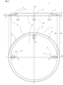
- a shutter disc 1 with three positioning mortises 4 in a first surface 2 and a rim 6 optionally provided with a flat 8 and/or a notch 9 is shown in Fig.2 .
- the shutter disc having a thickness t, the mortises having a length a, a width b, and a depth d (see also Fig.3 ) and being positioned with their longitudinal axes ⁇ 1-3 radially in a peripheral position at 0°, 90° and 180° of the disc perimeter.
- the disc also comprises three nicks 5 in a second surface 3 of the disc 1, positioned on an inner extension of the projection of axes ⁇ 1-3 , adjacent to mortises 4. These nicks can be used for a first placing step, e.g.
- Mortises can have a circumferential bevel 4' and tenons can have a circumferential chamfer 14', each alone or in cooperation with each other to ease matching of the two positioning elements.
- Mortises 4 can be positioned on axis ⁇ 1-3 in parallel and symmetric to it as indicated in solid lines, or alternatively right angled to axis ⁇ 1-3 as indicated in dashed lines and reference number 4", which will usually be also symmetric as referred to before.
- a similar shutter disc 1 with three positioning mortises 4 in the first surface 2 and a rim 6 here provided with a flat 8 is shown.
- the rim 6 also has a vertical extension which slightly towers over the first surface 2 and thereby may encompass the wafer bearing surface of the chuck 20 and sit on a peripheral chuck surface.
- the disks as shown in Fig.2 and Fig.3 can be designed very flat with a thickness t from 2 to 20 mm, or 3 to 10 mm
- the provision of a rim 6 of lower thickness t R can make it easy to clamp the disc on the chuck with usual wafer clamps, e.g. during sputtering processes.
- the rim 6 can be small but at the same time wide enough to provide place for the positioning flat 8 or notch 9.
- disc dimensions for a 300 mm chuck which are usual chuck dimensions to process 300 mm wafers, can be: 300.2 ⁇ D DO ⁇ 305 mm , 293 ⁇ D Ri ⁇ 298 mm .
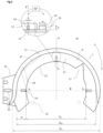
- a shutter disk arm 10 which can be mounted to the rod 26 of a rotation unit by a shaft 15 with flange and positioning slots 16 to level the sickle is shown in Fig.4 .
- a central mounting on the shaft as shown in Fig.1 , can be foreseen.
- the arm 10 further comprises a sickle 11 with a bearing surface 12 and sidewall 13.
- Three positioning tenants 14, each offset by 90° from the next tenant, are placed on the bearing surface 11 next to the inner diameter of the sickle, with their axes ⁇ 1-3 arranged radially towards the inner periphery of the sickle D Si .
- axes ⁇ 1-3 of mortises 4 and axes ⁇ 1-3 of the tenants 14 coincide and the inner periphery D Wi of the sidewall 13 encompasses the outer diameter D Do of the disc 1 on the bearing surface 12.
- the long dimension a of the mortise 4 should be provided considerably longer than the respective dimension m of the tenant 14 to enable thermal compensation.
- the difference should be at least 1 to 3 mm, depending on the maximal thermal load during processing.
- a flat side 8' and/or a nib 9' can be foreseen as shown in dashed lines.
- Reference number 17 refers to an optional out-cut to allow an optical sensor (not shown), to acknowledge correct positioning of the disc.
- the optical sensor can be mounted in a niche or a separate rest chamber for the arm and disc or can be integrated on the arm 10.
- One or more openings 18 as shown in dotted lines may be provided in the bearing surface 11 and a lower part of the side wall 13 to allow protrusions from the chuck or pins positioned further outward on the chuck to pass.
- Width w of the bearing surface should be from at least about 1.5 the length m of a tenon till about 30 mm to allow pins 21 to pass inside when lifting the disc 1.
- the magnifying glass in the upper part of the drawing shows on the left side a view from the center of the sickle 11 towards a tenant 14 on the bearing surface 12 and a sideview in a 90° perspective to the left side.
- Tenants may have a maximal length dimension m, a maximal width dimension n, and a height h whereby: 2 ⁇ m ⁇ 20 mm 2 ⁇ n ⁇ 20 mm 1 ⁇ h ⁇ 10 mm .
- mortises having a maximal length dimension a and a maximal width dimension b can be used with the following dimensions: 2 ⁇ a ⁇ 20 mm 2 ⁇ b ⁇ 20 mm 1 ⁇ d ⁇ 10 mm .
- Fig.5 shows further details of a positioning tenant 14 in top view.
- the tenant 14 comprising two circular edge sections of radius r, a straight middle part here of length l, and an upper finish with a circumferential chamfer 14'.
- r can be 2 mm and height h of the tenant can be also 2 mm.
- round tenants, tenants with an oval base or other convenient base forms as known to the man skilled in the art can be used.
- FIG.6 A further embodiment of an inventive shutter arm is shown in Fig.6 .
- circular tenons 14, mounted on an inner end of cantilevers 19, are used to position and hold the respective disc, which means the disc sits on the tenons only.
- the cantilevers project radially from the side wall 13 towards the center of the sickle 7.
- the tenons are placed in a 120° position from each other at a mere virtual inner periphery of the sickle D Si , so that there is no further need of the bearing surface 12 as shown in Fig.4 or Fig.7 .
- Axes ⁇ 1-3 cut each other in the center point of the sickle.
- Such a shutter arm can be combined with any of the previous disc embodiments when the mortises are arranged in a respective 120° position.
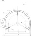
- FIG.7 A further inventive shutter arm in the form of a cut off disc is shown in Fig.7 .
- shutter arm 10" again has three positioning tenons with axes ⁇ 1-3 in a 0°, 90°, and 180° configuration.
- Bearing surface 12 in this case may comprise the whole or a part of the upper surface of the sickle 7 till its outer periphery D So , here comprising also the cut-off-line, when the thickness of the sickle, respectively bearing surface can be chosen big enough to provide stability and stiffness, which is easier for a paddle or disc-like sickle as shown with Fig.7 .
- a rim 13 can be provided also with such sickle types to ensure as mentioned mechanical properties.
- the inner periphery of the sickle D Si is only virtual here and, as an example, can be defined by an inner periphery touching the innermost position of two tenons 14 whereat a third tenon may be positioned away from the respective periphery, here in a further outward direction.
- each tenon can sit on the same or a different periphery with any embodiment of the invention, whereas positions near within, at the inner periphery or especially between the inner periphery and the rim are preferred due to ease and precision of positioning.
- Other positions of tenons and mortises may be chosen with any embodiment, with reference to different angular arrangements and/or different distances from the center for different tenons/mortises, up to the specific geometric needs within vacuum process chambers. And so can tenons and respective mortises of different geometry be combined with any of the shutter arm or disc embodiments as described in the examples.
Landscapes
- Physics & Mathematics (AREA)
- Engineering & Computer Science (AREA)
- Plasma & Fusion (AREA)
- Chemical & Material Sciences (AREA)
- Analytical Chemistry (AREA)
- Container, Conveyance, Adherence, Positioning, Of Wafer (AREA)
- Physical Vapour Deposition (AREA)
- Particle Accelerators (AREA)
- Magnetic Bearings And Hydrostatic Bearings (AREA)
Claims (15)
- Eine Prozessverschlussanordnung für ein Vakuumprozesssystem, umfassend:- eine Verschlussscheibe (1) mit einem im Wesentlichen kreisförmigen Außendurchmesser DDO, einer Dicke t, einer ersten Oberfläche (2) und einer zweiten Oberfläche (3), wobei die Scheibe mindestens drei Positionierungsnuten (4) in der ersten Oberfläche (2) in der Nähe des Außendurchmessers DDO aufweist, wobei jede Nut in Bezug auf eine radiale Achse ξ1-3 in einer xy-Ebene der Scheibe zentriert ist und zwei lange Seiten a aufweist, die parallel oder rechtwinklig zu der jeweiligen Achse ξ1-3 positioniert sind;- einen Verschlussarm (10), der eine Lagersichel (11) mit einem Innenumfang DSi und mindestens drei Positionierungszapfen angrenzend oder in der Nähe des Innendurchmessers DSi und mit Positionierungsnuten (4) korrespondierend, um die Scheibe zu positionieren, wenn sie auf die Positionierungszapfen oder auf eine optionale Lagerfläche der Sichel gesetzt wird.
- Die Anordnung nach Anspruch 1, wobei sich die Lagerfläche (12) radial vom Innenumfang DSi der Sichel erstreckt, wobei die Zapfen in der Nähe des Innendurchmessers DSi oder angrenzend daran angeordnet sind.
- Die Anordnung nach Anspruch 1 oder 2, wobei die Scheibe außerdem einen umlaufenden Rand (6, 6') aufweist, der sich horizontal zur Seite und/oder vertikal nach unten erstreckt, wobei die Zapfenlöcher optional innerhalb eines Innendurchmessers DRi des Randes oder innerhalb eines Vorsprungs des inneren Positionierrandes und benachbart zum Rand oder dem Vorsprung angeordnet sind.
- Die Anordnung nach einem der vorhergehenden Ansprüche, wobei die Zapfenlöcher eine rechteckige Grundgeometrie aufweisen, und/oder die Scheibe mit einem metallischen oder keramischen Werkstoff beschichtet ist oder aus einem solchen besteht.
- Die Anordnung nach einem der vorhergehenden Ansprüche, wobei der Verschlussarm eine Seitenwand umfasst, die zumindest teilweise einen Außenumfang DSo der Sichel bildet, wobei die äussere Peripherie DDo der Scheibe in die innere Peripherie DWi der Seitenwand passt, wobei die Seitenwand optional die Auflagefläche etwa halbkreisförmig umschließt, oder die Zapfen auf Auslegern montiert sind, die von der Seitenwand abstehen.
- Die Anordnung nach einem der vorhergehenden Ansprüche, wobei sich die Auflagefläche der Sichel über einen Winkelbereich von 180 - 360° des Innendurchmessers Dsi der Sichel erstreckt.
- Die Anordnung nach einem der vorhergehenden Ansprüche, wobei die Zapfen eine rechteckige, kreisförmige oder ovale Grundgeometrie aufweisen, wobei die Zapfen bevorzugt eine rechteckige oder quadratische Basis mit runden Ecken oder einer kreisförmigen Endgeometrie aufweisen.
- Die Anordnung nach einem der vorhergehenden Ansprüche, wobei der Arm aus einem Material mit einem Elastizitätsmodul von mindestens 100 GPa, insbesondere einem entsprechenden keramischen Material besteht und/oder die Zapfen an der ersten Oberfläche der Scheibe vorgesehen sind und die Nuten an der Auflagefläche der Sichel oder an von der Seitenwand abstehenden Auslegern vorgesehen sind.
- Eine Verschlussscheibe umfassend einen im Wesentlichen kreisförmigen Außendurchmesser DDo, einer Dicke t, einer ersten Oberfläche (2) und einer zweiten Oberfläche (3), wobei die Scheibe mindestens drei Positionierungsnuten (4) in der ersten Oberfläche (2) in der Nähe des Außendurchmessers DDo aufweist, wobei jede Nut zentriert und symmetrisch in Bezug auf eine Ebene zwischen einer radialen Achse ξ1-3 in einer xy-Ebene der Scheibe und der jeweiligen Vertikalen ist, und zwei lange Seiten a aufweist, die parallel oder rechtwinklig zur Achse ξ1-3 positioniert sind, sowie eine kurze Abmessung b und eine Tiefenabmessung d, wobei b < a.
- Eine Verschlussscheibe nach Anspruch 9, wobei die zweite Oberfläche mindestens eine Steuerkerbe umfasst.
- Ein Verschlussarm (10) mit einer Welle (15) mit Montagemitteln, einer Lagersichel(11) mit einem Innenumfang Dsi und mindestens drei Positionierungszapfen in der Nähe oder angrenzend an einen Innendurchmesser Dsi der Sichel, wobei jeder Zapfen auf einer radialen Achse η1-3 in einer xy-Ebene der Sichel und symmetrisch in Bezug auf eine Zentralebene positioniert ist, die sich entlang der jeweiligen Achsen η1-3 und der Höhenrichtung z erstreckt, und jeder Zapfen eine lange Abmessung m, eine kurze Abmessung n und eine Höhenabmessung h aufweist, wobei n ≤ m.
- Ein Vakuumprozesssystem, das eine Vakuumprozesskammer (31) umfasst, die einen Chuck mit Stiften (21) umfasst, die in einer Z-Richtung beweglich an einem Stiftantrieb (22) angebracht sind und eine Prozessverschlussanordnung nach einem der Ansprüche 1 bis 8, wobei der Arm 10 der Anordnung an einer Vakuumseite einer Stange mit einer vertikalen Drehachse R montiert ist und durch eine Durchführung an der Kammer montiert ist und in operativer Verbindung mit einem Verschlussantrieb an der Atmosphärenseite der Stange steht, um den Arm aus einer Nische der Verarbeitungskammer oder einem separaten Abteil in eine zentrale Position über dem Chuck zu drehen, wobei der Stiftantrieb vorzugsweise an der Prozesskammer auf der Atmosphären- oder der Vakuumseite montiert ist.
- Das Prozesssystem gemäß Anspruch 12 umfassend außerdem eine Steuereinheit, die mit dem Stiftantrieb und dem Verschlussantrieb verbunden ist, um eine Drehbewegung des Arms und die lineare Z-Bewegung der Stifte zu koordinieren, um den Arm mit der Scheibe zu drehen und die Scheibe anzuheben und abzusenken, wenn sich der Arm in der Zentralposition befindet.
- Verfahren zum Einsatz einer Prozessverschlussanordnung nach einem der Ansprüche 1 bis 8 in einer Kammer eines Vakuumprozesssystems gemäss Anspruch 12 oder 13 umfassend die folgenden Schritte:- Drehen der Anordnung in einer horizontalen Ebene aus der Nische oder dem separaten Abteil in eine zentrale Position über dem Chuck;- Ausfahren der Stifte, um die Scheibe von der Auflagefläche in eine horizontale Ebene über dem Arm anzuheben;- Zurückdrehen des leeren Arms in die Nische oder das separate Abteil;- Absenken und Zurückziehen der Stifte in die obere Fläche des Chucks, um den Chuck mit der Scheibe abzudecken;- Durchführen einer Konditionierung, einer Klebung oder eines Servicevorgangs in der Prozesskammer.
- Verfahren nach Anspruch 14 weiter umfassend die folgenden Schritte umfasst:- Ausfahren der Stifte, um die Scheibe aus dem Chuck in eine Ebene über dem Arm zu heben;- Drehen des leeren Arms aus der Nische oder dem separaten Abteil in die Zentralposition über dem Chuck und unter der Scheibe;- Absenken der Stifte auf die Auflagefläche der Sichel, wobei durch Eintreten der Zapfen in die Zapfenlöcher eine präzise Positionierung erfolgt;- Zurückziehen der Stifte in eine horizontale Ebene unterhalb des Arms;- Zurückdrehen des beladenen Arms in die Nische oder das separate Abteil.
Applications Claiming Priority (2)
| Application Number | Priority Date | Filing Date | Title |
|---|---|---|---|
| CH0701062021 | 2021-07-27 | ||
| PCT/EP2022/069134 WO2023006387A1 (en) | 2021-07-27 | 2022-07-08 | Process shutter arrangement |
Publications (2)
| Publication Number | Publication Date |
|---|---|
| EP4377992A1 EP4377992A1 (de) | 2024-06-05 |
| EP4377992B1 true EP4377992B1 (de) | 2025-06-18 |
Family
ID=82780921
Family Applications (1)
| Application Number | Title | Priority Date | Filing Date |
|---|---|---|---|
| EP22750674.8A Active EP4377992B1 (de) | 2021-07-27 | 2022-07-08 | Prozessblendenanordnung |
Country Status (7)
| Country | Link |
|---|---|
| US (1) | US20240347326A1 (de) |
| EP (1) | EP4377992B1 (de) |
| JP (1) | JP2024528013A (de) |
| KR (1) | KR20240039175A (de) |
| CN (1) | CN117716484A (de) |
| TW (1) | TW202314949A (de) |
| WO (1) | WO2023006387A1 (de) |
Family Cites Families (9)
| Publication number | Priority date | Publication date | Assignee | Title |
|---|---|---|---|---|
| JP3233496B2 (ja) * | 1993-04-14 | 2001-11-26 | 株式会社アルバック | 真空成膜装置 |
| US7008517B2 (en) | 2002-02-20 | 2006-03-07 | Applied Materials, Inc. | Shutter disk and blade for physical vapor deposition chamber |
| TWI431668B (zh) * | 2009-06-24 | 2014-03-21 | Ulvac Inc | 真空成膜裝置及真空成膜裝置之擋板位置檢測方法 |
| GB2476476B (en) * | 2009-12-23 | 2013-05-22 | Nanobeam Ltd | Charged particle beam system |
| JP2013057108A (ja) * | 2011-09-09 | 2013-03-28 | Ulvac Japan Ltd | 多元スパッタリング装置 |
| US9564348B2 (en) * | 2013-03-15 | 2017-02-07 | Applied Materials, Inc. | Shutter blade and robot blade with CTE compensation |
| WO2017207144A1 (en) | 2016-06-03 | 2017-12-07 | Evatec Ag | Plasma etch chamber and method of plasma etching |
| JP6991164B2 (ja) | 2016-06-15 | 2022-01-12 | エヴァテック・アーゲー | 真空処理チャンバ及び真空処理された板状基板の製造方法 |
| KR102500219B1 (ko) * | 2018-05-12 | 2023-02-14 | 어플라이드 머티어리얼스, 인코포레이티드 | 통합된 셔터 개라지를 갖는 사전-세정 챔버 |
-
2022
- 2022-07-06 TW TW111125321A patent/TW202314949A/zh unknown
- 2022-07-08 CN CN202280052299.8A patent/CN117716484A/zh active Pending
- 2022-07-08 EP EP22750674.8A patent/EP4377992B1/de active Active
- 2022-07-08 US US18/292,596 patent/US20240347326A1/en active Pending
- 2022-07-08 WO PCT/EP2022/069134 patent/WO2023006387A1/en not_active Ceased
- 2022-07-08 KR KR1020247006724A patent/KR20240039175A/ko active Pending
- 2022-07-08 JP JP2024505143A patent/JP2024528013A/ja active Pending
Also Published As
| Publication number | Publication date |
|---|---|
| CN117716484A (zh) | 2024-03-15 |
| TW202314949A (zh) | 2023-04-01 |
| WO2023006387A1 (en) | 2023-02-02 |
| KR20240039175A (ko) | 2024-03-26 |
| US20240347326A1 (en) | 2024-10-17 |
| JP2024528013A (ja) | 2024-07-26 |
| EP4377992A1 (de) | 2024-06-05 |
Similar Documents
| Publication | Publication Date | Title |
|---|---|---|
| US11587821B2 (en) | Substrate lift mechanism and reactor including same | |
| CN113906546B (zh) | 转位式多站处理室中的晶片放置修正 | |
| CN100499060C (zh) | 晶片定位方法和装置,晶片加工系统及晶片定位装置的晶片座旋转轴定位方法 | |
| TWI739470B (zh) | 前開式環件傳送盒 | |
| JP4580498B2 (ja) | カセットを位置合わせするための方法と装置 | |
| CN113795608B (zh) | 用于半导体处理腔室的基座提升 | |
| US6677166B2 (en) | Method for confirming alignment of a substrate support mechanism in a semiconductor processing system | |
| TW200527172A (en) | Auto-diagnostic method and apparatus | |
| KR20010071819A (ko) | 웨이퍼 캐리어 및 최소의 접촉으로 웨이퍼를 핸들링하기위한 방법 | |
| US8491252B2 (en) | Transport method for disk-shaped workpieces | |
| US20050111944A1 (en) | Compact wafer handling system with single axis robotic arm and prealigner-cassette elevator | |
| US20240347326A1 (en) | Process shutter arrangement | |
| EP1635988A2 (de) | Integriertes werkzeug mit austauschbaren nassbearbeitungskomponenten zur bearbeitung von mikromerkmal-werkstücken und automatisierte kalibriersysteme | |
| EP1866958B1 (de) | Vorrichtung zur substratausrichtung mit hoher geschwindigkeit | |
| US20240213060A1 (en) | Apparatuses for measuring gap between a substrate support plane and gas distribution device | |
| US7493231B2 (en) | Process for determining the actual position of a rotation axis of a transportation mechanism | |
| CN210287480U (zh) | 一种高通量分立掩膜装置 | |
| US20030154002A1 (en) | Method and apparatus for aligning a cassette handler | |
| US7717661B1 (en) | Compact multiple diameters wafer handling system with on-chuck wafer calibration and integrated cassette-chuck transfer | |
| CN105097606A (zh) | 一种遮挡盘及反应腔室 | |
| US8968532B2 (en) | Electrochemical processor alignment system | |
| EP4535410A1 (de) | Stiftlifter mit positionsausgleich | |
| CN112342494B (zh) | 一种高通量分立掩膜装置 | |
| CN120709199A (zh) | 一种同轴度测试仪、测试系统及同轴度的测试方法 |
Legal Events
| Date | Code | Title | Description |
|---|---|---|---|
| STAA | Information on the status of an ep patent application or granted ep patent |
Free format text: STATUS: UNKNOWN |
|
| STAA | Information on the status of an ep patent application or granted ep patent |
Free format text: STATUS: THE INTERNATIONAL PUBLICATION HAS BEEN MADE |
|
| PUAI | Public reference made under article 153(3) epc to a published international application that has entered the european phase |
Free format text: ORIGINAL CODE: 0009012 |
|
| STAA | Information on the status of an ep patent application or granted ep patent |
Free format text: STATUS: REQUEST FOR EXAMINATION WAS MADE |
|
| 17P | Request for examination filed |
Effective date: 20240117 |
|
| AK | Designated contracting states |
Kind code of ref document: A1 Designated state(s): AL AT BE BG CH CY CZ DE DK EE ES FI FR GB GR HR HU IE IS IT LI LT LU LV MC MK MT NL NO PL PT RO RS SE SI SK SM TR |
|
| GRAP | Despatch of communication of intention to grant a patent |
Free format text: ORIGINAL CODE: EPIDOSNIGR1 |
|
| STAA | Information on the status of an ep patent application or granted ep patent |
Free format text: STATUS: GRANT OF PATENT IS INTENDED |
|
| DAV | Request for validation of the european patent (deleted) | ||
| DAX | Request for extension of the european patent (deleted) | ||
| INTG | Intention to grant announced |
Effective date: 20241017 |
|
| P01 | Opt-out of the competence of the unified patent court (upc) registered |
Free format text: CASE NUMBER: APP_61008/2024 Effective date: 20241113 |
|
| P02 | Opt-out of the competence of the unified patent court (upc) changed |
Free format text: CASE NUMBER: APP_61047/2024 Effective date: 20241114 |
|
| GRAJ | Information related to disapproval of communication of intention to grant by the applicant or resumption of examination proceedings by the epo deleted |
Free format text: ORIGINAL CODE: EPIDOSDIGR1 |
|
| STAA | Information on the status of an ep patent application or granted ep patent |
Free format text: STATUS: REQUEST FOR EXAMINATION WAS MADE |
|
| GRAP | Despatch of communication of intention to grant a patent |
Free format text: ORIGINAL CODE: EPIDOSNIGR1 |
|
| STAA | Information on the status of an ep patent application or granted ep patent |
Free format text: STATUS: GRANT OF PATENT IS INTENDED |
|
| INTC | Intention to grant announced (deleted) | ||
| GRAJ | Information related to disapproval of communication of intention to grant by the applicant or resumption of examination proceedings by the epo deleted |
Free format text: ORIGINAL CODE: EPIDOSDIGR1 |
|
| STAA | Information on the status of an ep patent application or granted ep patent |
Free format text: STATUS: REQUEST FOR EXAMINATION WAS MADE |
|
| INTG | Intention to grant announced |
Effective date: 20250307 |
|
| GRAP | Despatch of communication of intention to grant a patent |
Free format text: ORIGINAL CODE: EPIDOSNIGR1 |
|
| STAA | Information on the status of an ep patent application or granted ep patent |
Free format text: STATUS: GRANT OF PATENT IS INTENDED |
|
| GRAS | Grant fee paid |
Free format text: ORIGINAL CODE: EPIDOSNIGR3 |
|
| INTG | Intention to grant announced |
Effective date: 20250415 |
|
| GRAA | (expected) grant |
Free format text: ORIGINAL CODE: 0009210 |
|
| STAA | Information on the status of an ep patent application or granted ep patent |
Free format text: STATUS: THE PATENT HAS BEEN GRANTED |
|
| AK | Designated contracting states |
Kind code of ref document: B1 Designated state(s): AL AT BE BG CH CY CZ DE DK EE ES FI FR GB GR HR HU IE IS IT LI LT LU LV MC MK MT NL NO PL PT RO RS SE SI SK SM TR |
|
| REG | Reference to a national code |
Ref country code: GB Ref legal event code: FG4D |
|
| REG | Reference to a national code |
Ref country code: CH Ref legal event code: EP |
|
| REG | Reference to a national code |
Ref country code: DE Ref legal event code: R096 Ref document number: 602022016150 Country of ref document: DE |
|
| REG | Reference to a national code |
Ref country code: CH Ref legal event code: EP |
|
| REG | Reference to a national code |
Ref country code: IE Ref legal event code: FG4D |
|
| PG25 | Lapsed in a contracting state [announced via postgrant information from national office to epo] |
Ref country code: FI Free format text: LAPSE BECAUSE OF FAILURE TO SUBMIT A TRANSLATION OF THE DESCRIPTION OR TO PAY THE FEE WITHIN THE PRESCRIBED TIME-LIMIT Effective date: 20250618 |
|
| PGFP | Annual fee paid to national office [announced via postgrant information from national office to epo] |
Ref country code: DE Payment date: 20250901 Year of fee payment: 4 |
|
| REG | Reference to a national code |
Ref country code: LT Ref legal event code: MG9D |
|
| PG25 | Lapsed in a contracting state [announced via postgrant information from national office to epo] |
Ref country code: GR Free format text: LAPSE BECAUSE OF FAILURE TO SUBMIT A TRANSLATION OF THE DESCRIPTION OR TO PAY THE FEE WITHIN THE PRESCRIBED TIME-LIMIT Effective date: 20250919 Ref country code: NO Free format text: LAPSE BECAUSE OF FAILURE TO SUBMIT A TRANSLATION OF THE DESCRIPTION OR TO PAY THE FEE WITHIN THE PRESCRIBED TIME-LIMIT Effective date: 20250918 |
|
| PG25 | Lapsed in a contracting state [announced via postgrant information from national office to epo] |
Ref country code: BG Free format text: LAPSE BECAUSE OF FAILURE TO SUBMIT A TRANSLATION OF THE DESCRIPTION OR TO PAY THE FEE WITHIN THE PRESCRIBED TIME-LIMIT Effective date: 20250618 |
|
| PG25 | Lapsed in a contracting state [announced via postgrant information from national office to epo] |
Ref country code: HR Free format text: LAPSE BECAUSE OF FAILURE TO SUBMIT A TRANSLATION OF THE DESCRIPTION OR TO PAY THE FEE WITHIN THE PRESCRIBED TIME-LIMIT Effective date: 20250618 |
|
| PGFP | Annual fee paid to national office [announced via postgrant information from national office to epo] |
Ref country code: AT Payment date: 20251020 Year of fee payment: 4 |
|
| PG25 | Lapsed in a contracting state [announced via postgrant information from national office to epo] |
Ref country code: RS Free format text: LAPSE BECAUSE OF FAILURE TO SUBMIT A TRANSLATION OF THE DESCRIPTION OR TO PAY THE FEE WITHIN THE PRESCRIBED TIME-LIMIT Effective date: 20250918 |
|
| REG | Reference to a national code |
Ref country code: NL Ref legal event code: MP Effective date: 20250618 |
|
| PG25 | Lapsed in a contracting state [announced via postgrant information from national office to epo] |
Ref country code: LV Free format text: LAPSE BECAUSE OF FAILURE TO SUBMIT A TRANSLATION OF THE DESCRIPTION OR TO PAY THE FEE WITHIN THE PRESCRIBED TIME-LIMIT Effective date: 20250618 |
|
| PG25 | Lapsed in a contracting state [announced via postgrant information from national office to epo] |
Ref country code: NL Free format text: LAPSE BECAUSE OF FAILURE TO SUBMIT A TRANSLATION OF THE DESCRIPTION OR TO PAY THE FEE WITHIN THE PRESCRIBED TIME-LIMIT Effective date: 20250618 |
|
| REG | Reference to a national code |
Ref country code: DE Ref legal event code: R079 Ref document number: 602022016150 Country of ref document: DE Free format text: PREVIOUS MAIN CLASS: H01L0021677000 Ipc: H10P0072300000 |
|
| PG25 | Lapsed in a contracting state [announced via postgrant information from national office to epo] |
Ref country code: PT Free format text: LAPSE BECAUSE OF FAILURE TO SUBMIT A TRANSLATION OF THE DESCRIPTION OR TO PAY THE FEE WITHIN THE PRESCRIBED TIME-LIMIT Effective date: 20251020 |
|
| REG | Reference to a national code |
Ref country code: AT Ref legal event code: MK05 Ref document number: 1805036 Country of ref document: AT Kind code of ref document: T Effective date: 20250618 |
|
| PG25 | Lapsed in a contracting state [announced via postgrant information from national office to epo] |
Ref country code: IS Free format text: LAPSE BECAUSE OF FAILURE TO SUBMIT A TRANSLATION OF THE DESCRIPTION OR TO PAY THE FEE WITHIN THE PRESCRIBED TIME-LIMIT Effective date: 20251018 |
|
| PG25 | Lapsed in a contracting state [announced via postgrant information from national office to epo] |
Ref country code: AT Free format text: LAPSE BECAUSE OF FAILURE TO SUBMIT A TRANSLATION OF THE DESCRIPTION OR TO PAY THE FEE WITHIN THE PRESCRIBED TIME-LIMIT Effective date: 20250618 Ref country code: SM Free format text: LAPSE BECAUSE OF FAILURE TO SUBMIT A TRANSLATION OF THE DESCRIPTION OR TO PAY THE FEE WITHIN THE PRESCRIBED TIME-LIMIT Effective date: 20250618 |
|
| PG25 | Lapsed in a contracting state [announced via postgrant information from national office to epo] |
Ref country code: CZ Free format text: LAPSE BECAUSE OF FAILURE TO SUBMIT A TRANSLATION OF THE DESCRIPTION OR TO PAY THE FEE WITHIN THE PRESCRIBED TIME-LIMIT Effective date: 20250618 |
|
| PG25 | Lapsed in a contracting state [announced via postgrant information from national office to epo] |
Ref country code: PL Free format text: LAPSE BECAUSE OF FAILURE TO SUBMIT A TRANSLATION OF THE DESCRIPTION OR TO PAY THE FEE WITHIN THE PRESCRIBED TIME-LIMIT Effective date: 20250618 |
|
| PG25 | Lapsed in a contracting state [announced via postgrant information from national office to epo] |
Ref country code: EE Free format text: LAPSE BECAUSE OF FAILURE TO SUBMIT A TRANSLATION OF THE DESCRIPTION OR TO PAY THE FEE WITHIN THE PRESCRIBED TIME-LIMIT Effective date: 20250618 |
|
| PG25 | Lapsed in a contracting state [announced via postgrant information from national office to epo] |
Ref country code: SK Free format text: LAPSE BECAUSE OF FAILURE TO SUBMIT A TRANSLATION OF THE DESCRIPTION OR TO PAY THE FEE WITHIN THE PRESCRIBED TIME-LIMIT Effective date: 20250618 |
|
| PG25 | Lapsed in a contracting state [announced via postgrant information from national office to epo] |
Ref country code: ES Free format text: LAPSE BECAUSE OF FAILURE TO SUBMIT A TRANSLATION OF THE DESCRIPTION OR TO PAY THE FEE WITHIN THE PRESCRIBED TIME-LIMIT Effective date: 20250618 |
|
| REG | Reference to a national code |
Ref country code: CH Ref legal event code: H13 Free format text: ST27 STATUS EVENT CODE: U-0-0-H10-H13 (AS PROVIDED BY THE NATIONAL OFFICE) Effective date: 20260224 |
|
| PG25 | Lapsed in a contracting state [announced via postgrant information from national office to epo] |
Ref country code: RO Free format text: LAPSE BECAUSE OF FAILURE TO SUBMIT A TRANSLATION OF THE DESCRIPTION OR TO PAY THE FEE WITHIN THE PRESCRIBED TIME-LIMIT Effective date: 20250618 Ref country code: LU Free format text: LAPSE BECAUSE OF NON-PAYMENT OF DUE FEES Effective date: 20250708 |
|
| REG | Reference to a national code |
Ref country code: DE Ref legal event code: R097 Ref document number: 602022016150 Country of ref document: DE |
|
| REG | Reference to a national code |
Ref country code: BE Ref legal event code: MM Effective date: 20250731 |
|
| PG25 | Lapsed in a contracting state [announced via postgrant information from national office to epo] |
Ref country code: MC Free format text: LAPSE BECAUSE OF FAILURE TO SUBMIT A TRANSLATION OF THE DESCRIPTION OR TO PAY THE FEE WITHIN THE PRESCRIBED TIME-LIMIT Effective date: 20250618 |
|
| PG25 | Lapsed in a contracting state [announced via postgrant information from national office to epo] |
Ref country code: DK Free format text: LAPSE BECAUSE OF FAILURE TO SUBMIT A TRANSLATION OF THE DESCRIPTION OR TO PAY THE FEE WITHIN THE PRESCRIBED TIME-LIMIT Effective date: 20250618 |
|
| PG25 | Lapsed in a contracting state [announced via postgrant information from national office to epo] |
Ref country code: BE Free format text: LAPSE BECAUSE OF NON-PAYMENT OF DUE FEES Effective date: 20250731 Ref country code: IT Free format text: LAPSE BECAUSE OF FAILURE TO SUBMIT A TRANSLATION OF THE DESCRIPTION OR TO PAY THE FEE WITHIN THE PRESCRIBED TIME-LIMIT Effective date: 20250618 |
|
| PG25 | Lapsed in a contracting state [announced via postgrant information from national office to epo] |
Ref country code: CH Free format text: LAPSE BECAUSE OF NON-PAYMENT OF DUE FEES Effective date: 20250731 |
|
| PLBE | No opposition filed within time limit |
Free format text: ORIGINAL CODE: 0009261 |
|
| STAA | Information on the status of an ep patent application or granted ep patent |
Free format text: STATUS: NO OPPOSITION FILED WITHIN TIME LIMIT |
|
| REG | Reference to a national code |
Ref country code: CH Ref legal event code: L10 Free format text: ST27 STATUS EVENT CODE: U-0-0-L10-L00 (AS PROVIDED BY THE NATIONAL OFFICE) Effective date: 20260430 |