EP4376940B1 - Tragbarer applikator und hautbehandlungskit - Google Patents
Tragbarer applikator und hautbehandlungskit Download PDFInfo
- Publication number
- EP4376940B1 EP4376940B1 EP22754402.0A EP22754402A EP4376940B1 EP 4376940 B1 EP4376940 B1 EP 4376940B1 EP 22754402 A EP22754402 A EP 22754402A EP 4376940 B1 EP4376940 B1 EP 4376940B1
- Authority
- EP
- European Patent Office
- Prior art keywords
- waveguide
- applicator
- microwave
- skin
- microwave radiation
- Prior art date
- Legal status (The legal status is an assumption and is not a legal conclusion. Google has not performed a legal analysis and makes no representation as to the accuracy of the status listed.)
- Active
Links
Images






Classifications
-
- A—HUMAN NECESSITIES
- A61—MEDICAL OR VETERINARY SCIENCE; HYGIENE
- A61N—ELECTROTHERAPY; MAGNETOTHERAPY; RADIATION THERAPY; ULTRASOUND THERAPY
- A61N1/00—Electrotherapy; Circuits therefor
- A61N1/18—Applying electric currents by contact electrodes
- A61N1/32—Applying electric currents by contact electrodes alternating or intermittent currents
- A61N1/328—Applying electric currents by contact electrodes alternating or intermittent currents for improving the appearance of the skin, e.g. facial toning or wrinkle treatment
-
- A—HUMAN NECESSITIES
- A61—MEDICAL OR VETERINARY SCIENCE; HYGIENE
- A61N—ELECTROTHERAPY; MAGNETOTHERAPY; RADIATION THERAPY; ULTRASOUND THERAPY
- A61N5/00—Radiation therapy
- A61N5/02—Radiation therapy using microwaves
- A61N5/022—Apparatus adapted for a specific treatment
-
- A—HUMAN NECESSITIES
- A61—MEDICAL OR VETERINARY SCIENCE; HYGIENE
- A61B—DIAGNOSIS; SURGERY; IDENTIFICATION
- A61B18/00—Surgical instruments, devices or methods for transferring non-mechanical forms of energy to or from the body
- A61B18/18—Surgical instruments, devices or methods for transferring non-mechanical forms of energy to or from the body by applying electromagnetic radiation, e.g. microwaves
- A61B18/1815—Surgical instruments, devices or methods for transferring non-mechanical forms of energy to or from the body by applying electromagnetic radiation, e.g. microwaves using microwaves
-
- A—HUMAN NECESSITIES
- A61—MEDICAL OR VETERINARY SCIENCE; HYGIENE
- A61N—ELECTROTHERAPY; MAGNETOTHERAPY; RADIATION THERAPY; ULTRASOUND THERAPY
- A61N5/00—Radiation therapy
- A61N5/01—Devices for producing movement of radiation source during therapy
-
- A—HUMAN NECESSITIES
- A61—MEDICAL OR VETERINARY SCIENCE; HYGIENE
- A61N—ELECTROTHERAPY; MAGNETOTHERAPY; RADIATION THERAPY; ULTRASOUND THERAPY
- A61N5/00—Radiation therapy
- A61N5/02—Radiation therapy using microwaves
- A61N5/04—Radiators for near-field treatment
-
- A—HUMAN NECESSITIES
- A61—MEDICAL OR VETERINARY SCIENCE; HYGIENE
- A61B—DIAGNOSIS; SURGERY; IDENTIFICATION
- A61B17/00—Surgical instruments, devices or methods
- A61B2017/00743—Type of operation; Specification of treatment sites
- A61B2017/00747—Dermatology
-
- A—HUMAN NECESSITIES
- A61—MEDICAL OR VETERINARY SCIENCE; HYGIENE
- A61B—DIAGNOSIS; SURGERY; IDENTIFICATION
- A61B18/00—Surgical instruments, devices or methods for transferring non-mechanical forms of energy to or from the body
- A61B2018/00571—Surgical instruments, devices or methods for transferring non-mechanical forms of energy to or from the body for achieving a particular surgical effect
- A61B2018/00577—Ablation
-
- A—HUMAN NECESSITIES
- A61—MEDICAL OR VETERINARY SCIENCE; HYGIENE
- A61B—DIAGNOSIS; SURGERY; IDENTIFICATION
- A61B90/00—Instruments, implements or accessories specially adapted for surgery or diagnosis and not covered by any of the groups A61B1/00 - A61B50/00, e.g. for luxation treatment or for protecting wound edges
- A61B90/39—Markers, e.g. radio-opaque or breast lesions markers
- A61B2090/3937—Visible markers
-
- A—HUMAN NECESSITIES
- A61—MEDICAL OR VETERINARY SCIENCE; HYGIENE
- A61N—ELECTROTHERAPY; MAGNETOTHERAPY; RADIATION THERAPY; ULTRASOUND THERAPY
- A61N5/00—Radiation therapy
- A61N2005/002—Cooling systems
- A61N2005/005—Cooling systems for cooling the radiator
-
- A—HUMAN NECESSITIES
- A61—MEDICAL OR VETERINARY SCIENCE; HYGIENE
- A61N—ELECTROTHERAPY; MAGNETOTHERAPY; RADIATION THERAPY; ULTRASOUND THERAPY
- A61N5/00—Radiation therapy
- A61N2005/002—Cooling systems
- A61N2005/007—Cooling systems for cooling the patient
Definitions
- the invention is directed to a handheld applicator for treating a skin by means of microwave radiation.
- the handheld applicator comprises an applicator housing and a microwave emitter configured to emit microwave radiation for treating tissue in a target area.
- the invention is also directed to a skin treatment kit, comprising the handheld applicator and the applicator pad.
- Skin treatment is a growing market, and there is a consumer-led desire for non-invasive treatments for disease and skin rejuvenation.
- the skin is the largest organ of the human body and is made up of different layers each of which have a different composition which causes a different reaction to heating in each layer.
- Ablation prompts a number of responses from skin tissue.
- ablation of a region of skin tissue can stop that region from functioning and may stimulate healing in the skin as the ablated region is treated as a wound by the skin.
- Ablation may be used in the treatment of skin cancer, lesions, or tumours.
- Treatment of skin tissue with sufficient heating can stimulate sub-surface changes in the skin by denaturing proteins causing a healing response from the skin tissue. It is known that the use of heat beneath the surface of the skin, even without causing ablation, can stimulate new skin growth and collagen growth which will cause skin to look more youthful, cause the skin to tighten and reduce the severity of wrinkles.
- RF electromagnetic radiation e.g. with a frequency between 10 kHz and 300 MHz
- infrared or near infrared laser light to cause heating in skin tissue.
- Skin appears as a dielectric medium to RF radiation.
- RF radiation passes through the skin, heat is generated at and beneath the surface of the skin tissue.
- the laser light heats skin tissue by absorption of the laser light as it passes into the skin.
- Cooling can, for example, be achieved through the use of cryogenic sprays or thermo-electric cooling using Freon, tetrafluoroethane or other such refrigerants.
- RF electromagnetic waves penetrate deep into the skin, which means it can be difficult to predict and control the depth to which heating occurs.
- dielectric heating induced by low frequency RF radiation causes the heat to be spread by conduction through the skin tissue. Heat transfer by conduction can lead to uneven heating, and when cooling is applied to the skin it counteracts and disrupts the conduction of heat to cause a reduced heating effect or to eliminate any heating.
- Laser light is absorbed only in a small region of skin tissue where the laser light is incident. This causes significant heating in those regions generating hotspots from which heat is then transferred to the surrounding skin tissue by conduction.
- the hotspots can cause uneven heating and the overall heating is affected in the same way by cooling as RF radiation.
- the depth of penetration of laser light and therefore the heating effect depends on skin composition at the location where the laser light is applied and is therefore unpredictable. This can lead to variation in results between different parts of the body and different patients.
- the waveguide cavity may be considered exhibiting different sections which, for example, are constituted by the first waveguide section, the second waveguide section, and/or the tapered waveguide section.
- the waveguide sections may be integrally formed or can be made of different components which are attached to each other, for example by welding.
- the second waveguide section may be made from commercially available waveguide sections fulfilling defined standards.
- the second waveguide section is a WR62 waveguide.
- the first waveguide section, the second waveguide section, and/or the tapered waveguide section may have an inner and/or outer rectangular cross-section.
- other shapes in the cross-sectional view of the waveguide sections are possible, such as circular, oval, or square-shaped.
- the cross-section extends perpendicular to the longitudinal extension of the waveguide sections, i.e. perpendicular to the propagation of the microwave radiation through the respective waveguide sections.
- the waveguide sections can be dimensioned to carry the microwave frequency electromagnetic energy in a fundamental mode, which interacts with the boundary condition set up by the waveguide sections such that the electromagnetic field emitted by the waveguide is in a quasi-TEM mode.
- the cross-sectional area is an area parallel to the cross-section and confined by the inner surface of the respective waveguide section.
- the cross-sectional area of the first waveguide section and/or the second waveguide section is constant along their axial extension (i.e. along the direction of propagation of the microwave radiation through the waveguide section).
- the inner and/or outer cross-sectional area of the tapered waveguide section at least partially changes along its axial extension.
- the inner cross-sectional area diminishes along the extension from the second waveguide section to the first waveguide section.
- the outer cross-sectional area of the tapered waveguide section may be constant.
- the tapered waveguide section may be considered an adapter unit for reducing the cross-sectional area such that the first waveguide section can be attached to the second waveguide section.
- the first waveguide section, the second waveguide section and/or the tapered waveguide section may include a maximum diameter parallel to the plane of the cross section.
- the maximum diameter may be the radius in case of a circular cross-section or a diagonal line in case of a rectangular or square shaped cross-section of the respective waveguide sections.
- the maximum diameter of the second waveguide section is greater than the maximum diameter of the first waveguide section.
- the cross-sectional area may be defined by the sides of the rectangle.
- the difference in the cross-sectional area may be constituted in that one or both sides of the rectangular are smaller with the first waveguide section compared to the respective sides of the second waveguide section.
- the antenna for emitting microwave radiation can be constituted by any means which is capable of emitting microwave radiation.
- the second waveguide section includes a SMA (SubMiniature version A) connector.
- the antenna may be provided in this case as an extension of the inner conductor of the SMA cable beyond the dielectric material of the SMA cable into the cavity of the second waveguide section.
- the connector includes the antenna, for example the antenna is fixedly connected to the connector. If the SMA cable is connected to the connector, the inner conductor of the SMA cable is electrically connected to the antenna.
- the antenna may be fixedly positioned within the second waveguide section.
- the microwave radiation emitted by the antenna is guided by the second waveguide section to the tapered waveguide section and, subsequently, to the first waveguide section.
- the microwave radiation may leave the waveguide at the treatment aperture arranged at the first waveguide section.
- the first waveguide section preferably includes two opposing wall sections, for example two opposing sides of a rectangular or square shaped first waveguide section.
- the two opposing wall sections may be any two sections of the waveguide body which oppose each other.
- the wall section, in particular the two opposing wall sections may be identified in that, without the presence of the meta surface structure, there is a drop of the electrical field of the microwave radiation directly adjacent to the wall section(s). This means, at the wall section(s), the electric field of the microwave radiation guided through the respective microwave sections may be parallel or almost parallel to the surface of the opposing wall sections.
- the pattern on the wall section(s) allows the electric fields to be present at the wall section(s) where normally, without the pattern, the electric field would be zero.
- meta surface structure a material is meant which has a negative refractive index.
- the meta surface structure is arranged to create a quasi-perfect magnetic conductor boundary condition at the two opposing wall sections.
- the quasi-perfect magnetic conductor exhibits its characteristics solely at or close to a predetermined frequency which preferably is the frequency of the microwave radiation guided through the waveguide.
- the shape and configuration of the pattern of the conductive layer provides the characteristics as a quasi-perfect magnetic conductor.
- the shape and the configuration of the pattern refers to the two-dimensional extension of the conductive layer since, being manufactured as a microstrip in a preferred embodiment, the conductive layer includes a constant thickness along the two-dimensional extension of the pattern.
- the pattern is composed of a plurality of unit cells whereby each unit cell is identical to another unit cell.
- the unit cells are arranged in a periodic manner over the meta surface structure. This means, the meta surface structure includes a periodicity whose period is defined by the unit cell.
- each unit cell comprises at least one capacitive portion which may form a capacitor with a capacitive portion of an adjacent unit cell and/or an additional capacitive portion of the same unit cell.
- the inductive portion constitutes an inductor, either alone or in conjunction with another inductive portion of an adjacent unit cell and/or an additional inductive portion of the same unit cell.
- the inductive portion and the capacitive portion are electrically connected to each other by the intermediate portion.
- the shape of the intermediate portion can be chosen such that it provides sufficient electrical connection between the capacitive portion and the inductive portion.
- the capacitive portion and/or the inductive portion may be shaped as rectangles.
- the length of the inductive portion is significantly larger than the width of the inductive portion (e.g. the inductive portion may be substantially elongate).
- the inductive portion may be considered a wire.
- the capacitive portion may have a width and a length whose dimensions are similar to each other.
- the capacitive portion may be a square. This allows to provide sufficient volume for gathering electrons in order to provide a capacitor.
- the dimensions such as the width and/or the length of the capacitive portion and/or the inductive portion are chosen that the resonance frequency of the electric circuit including the capacitive portion and inductive portion corresponds to the frequency of the microwave radiation.
- the dimensions may be selected to set the resonant frequency of a resonant circuit formed by the combined inductance of all the inductive portions of the pattern and the combined capacitance of all the capacitances of the pattern.
- the capacitance and inductance of the lattice can be modified.
- the modification of the shape to change the inductance and capacitance changes the resonant frequency of the pattern/lattice which dictates the operational frequency.
- the dimensions are chosen to be most optimal at 14.5GHz.
- Scaling may occur vertically and/or horizontally to the pattern and/or the unit cell evenly so that the shape remains the same but increase or decreases in overall size. The thickness of the shape may never be scaled and remain constant regardless of the pattern's final dimensions.
- L and C are determined by capacitance and inductance of the pattern within the guide. By altering the size, the dimensions of the L and C sections change which then change the resonant frequency.
- the dimensions may be selected by using a simulation simulating the microstrip and its interaction with the microwave radiation. As a starting point, the response of a single unit cell or the response of a single unit cell interacting with its directly adjacent unit cells to the microwave radiation may be simulated. If the dimensions of the capacitive portion and/or the inductive portion provide the desired resonance effect, the simulation may be extended to the whole pattern.
- the capacitive portion may have a width and/or length between 0.2 mm and 2 mm, in particular between 0.5 mm and 1 mm.
- the inductive portion may have a length between 0.2 mm and 2 mm, in particular between 0.5 mm and 1 mm, and a width between 0.05 mm and 0.5 mm, in particular between 0.1 mm and 0.3 mm.
- the intermediate portion may have a width between 0.2 mm and 2 mm, in particular between 0.5 mm and 1 mm.
- phase of the electric field of the microwave radiation at the meta surface structure is of interest.
- a perfect electrical conductor (PEC) in this situation is usually at 180° phase shift and a perfect magnetic conductor (PMC) would be at the point where the phase has changed by 180° (i.e. to 0°). Through the resonance, it changes from 180° to -180° and on the way passes through 0°, which is the typical response of a PMC.
- the quasi-perfect magnetic conductor exhibits some losses.
- the input power input in the first waveguide section may be 0.5 W and the output is 0.43 W which means that 0.07 W is lost in the dielectric materials and metals within the first waveguide section. Such an amount of loss is not considered to be enough to cause any unwanted damage and shows that most of the energy is propagating to the end of the first waveguide section.
- the wall section in particular the two opposing wall sections, are preferably completely covered with the meta surface structure in the axial direction and/or in a direction perpendicular to the axial direction (e.g. a width direction of the first waveguide section in case of a rectangular configuration in a cross-sectional view).
- the unit cells are arranged in a row, wherein preferably the pattern includes multiple rows.
- the unit cell comprises at least two capacitive portions wherein the inductive portion is arranged between the two capacitive portions.
- these two capacitive portions do not form a capacitor between each other, but with other capacitive portions either from the same unit cell or from adjacent unit cells.
- the capacitive portion is arranged in a corner of the unit cell, wherein preferably the capacitive portion is spaced apart from a border of the unit cell, wherein further preferably the given unit cell comprises four capacitive portions each of which is arranged in a different corner of that unit cell.
- the border of the unit cell may be an imaginary line which separates the unit cell from an adjacent unit cell.
- the border of the unit cell preferably extends around the appearance of the unit cell.
- a pattern may be divided into identical unit cells by means of the border. As such, the border of the unit cell does not need to coincide with an edge of the capacitive portion and/or the inductive portion.
- the distance or separation of the border of the unit cell to the capacitive portion allows the formation of a capacitor with a capacitive portion of an adjacent unit cell.
- the gap between the two capacitive portions forming a capacitor is twice the distance of the border of the unit cell to the capacitive portion in this embodiment.
- the inductive portion extends to the border of the unit cell, wherein preferably the inductive portion of one unit cell is connected to the inductive portion of another unit cell.
- two unit cells are electrically connected by means of the respective inductive portions.
- the inductive portions of the two unit cells are arranged in a straight line.
- the inductor constituted by the two inductive portions of the two unit cells may have a length which is twice the length of the respective inductive portion.
- the unit cell is rectangular, wherein preferably the unit cell includes two axis of mirror symmetry which are perpendicular to each other, wherein further preferably the inductive portions (for example four inductive portions) extend in a direction of the axis of mirror symmetry.
- Waveguides for electromagnetic energy may have Transverse Electric (TE) or Transverse Magnetic (TM) modes.
- the fundamental mode of a rectangular waveguide (a waveguide with a rectangular cross-section in a plane perpendicular to the length of the waveguide) or a circular waveguide is a TE mode.
- the fundamental mode of a rectangular waveguide is the TE10 mode, and the fundamental mode of a circular waveguide is the TE11 mode.
- Other shapes of waveguide, for example a hexagonal or square waveguide, may have different fundamental modes.
- the first waveguide section includes a treatment aperture for being placed on the skin.
- the cover may act as a separator for avoiding contact of the skin with the handpiece, in particular the waveguide. This may provide a sterile contact between the skin and the handpiece if an outer surface of the handpiece cannot be sterilized to a sufficient degree.
- the cover can be the sterile component for being in direct contact with the skin.
- the cover may be a disposable component such that a new cover may be used for every patient.
- the cover may be a component that can be sterilised using common sterilisation protocols.
- the waveguide of the handpiece is the waveguide as described above.
- the handpiece may include waveguides having a different structural and technical configuration.
- a conductor of the microwave source may act as an antenna arranged within the cavity of the waveguide.
- the antenna may be configured as a slotted microstrip antenna.
- the handpiece further comprises a microwave transmission line which connects the microwave source to the waveguide.
- the microwave transmission line may be a coaxial cable which generally includes an inner conductor and an outer conductor which are coaxially arranged and separated by a dielectric material.
- the dielectric material as well as the outer conductor generally have a cylindrical shape.
- the microwave transmission line may be flexible and can be a SMA cable.
- microwave transmission line is interposed between the microwave source and the waveguide, transmission losses can be reduced since the distance between the microwave source and the waveguide is small due to their arrangement within the handpiece.
- the handpiece further includes a heat sink thermally coupled to the microwave source.
- the microwave source can produce a considerable amount of heat during generation of microwave energy.
- the heat sink is provided with the microwave source.
- the microwave source is (directly) attached to the heat sink.
- the heatsink is preferably made of a thermally conductive material, such as metal.
- a thermally conductive material such as metal.
- aluminium is chosen as it is also lightweight.
- the heatsink may also provide stability to the microwave source, in particular in case the microwave source is arranged on a circuit board or is constituted by a printed circuit board.
- the heatsink may have an extension that corresponds with the dimensions of the microwave source such that the heatsink supports the microwave source over its complete extension.
- the heatsink preferably made from a metal material may also provide stability and/or support for the whole handpiece.
- This means optional other components of the handpiece may be attached to the heatsink.
- a housing and/or the waveguide may be attached to the heatsink.
- the heatsink includes at least one fin, wherein preferably the handpiece further includes a fan for providing a flow of air along the at least one fin.
- the heatsink may comprise a base plate and at least one fin.
- the microwave source, the housing, the fan and/or the waveguide may be attached to the base plate.
- the at least one fin is arranged on the base plate and protrudes from the base plate.
- the at least one fin is provided for increasing the surface area of the heatsink such that the heatsink can be more efficiently cooled by the fan.
- the at least one fin may comprise a direction of extension wherein the fan is arranged to provide the flow of air along the direction of extension.
- the fan may be arranged at a side face of the at least one fin, for example perpendicular to the direction of extension of the at least one fin.
- the handpiece further comprises a housing, wherein preferably the housing includes vents which are optionally arranged at opposing sides of the heat.
- the housing may house all components of the handpiece. This means, all components of the handpiece are arranged within the housing.
- the housing may include a top shell and a bottom shell which can provide a cavity for the microwave source, the heat sink, and/or the fan.
- the waveguide may be covered by a waveguide cover which can be considered as a part of the housing. The waveguide cover together with the top shell and the bottom shell may completely define the outer surface of the handpiece.
- the housing may comprise one, two or more vents which provide a fluid communication between the inside of the housing and the outside of the housing.
- the vents are provided for exchanging air between the inside of the housing and the outside of the housing, preferably driven by the operation of the fan.
- the handpiece further comprises a control portion (e.g. controller) controlling the microwave source.
- a control portion e.g. controller
- the present invention provides a treatment apparatus and/or a handheld applicator for skin treatment in which the handpiece for contacting a region of skin and/or a handheld applicator are configured to establish heating or ablation at a predetermined and preferably controllable (i.e. selectable) depth below the surface of the skin tissue.
- the skin treatment apparatus may be configured to provide a substantially uniform heating effect.
- the treatment apparatus is preferably controllable to deliver the microwave electromagnetic energy in a manner that induces a thermal profile in the region of skin, the thermal profile having a maximum temperature that occurs at a predetermined distance beneath a surface of the region of skin.
- the skin is composed of three layers.
- the top layer is called the epidermis
- the middle layer is the dermis
- the bottom layer is the subcutaneous layer.
- the dermis contains many of the structural features which dictate the properties of skin such as protein fibres, e.g. collagen. Hair follicles and sweat glands are also located in the dermis.
- heat follicles and sweat glands are also located in the dermis.
- heat is applied to the dermis it is desirable to protect the epidermis from damage caused by the heat.
- One advantage of the microwave frequency electromagnetic energy of the present invention is the ability of to deliver heat instantaneously.
- the skin treatment apparatus may be capable of producing controlled, predictable, and uniform heating or ablation in the dermis.
- the invention may also provide a method of treating skin tissue with microwave frequency electromagnetic energy, the method comprising: positioning the handpiece of the skin treatment apparatus described above over a region of skin; launching microwave electromagnetic energy into the waveguide; and controlling delivery of the microwave electromagnetic energy in a manner that induces a thermal profile in the region of skin, the thermal profile having a maximum temperature that occurs at a predetermined distance beneath a surface of the region of skin.
- the treatment aperture of the waveguide may have a cover, and when the aperture is positioned over the treatment region of skin tissue the cover may be in contact with the surface of the treatment region of skin tissue.
- the skin treatment apparatus preferably must be capable of producing heat between 40°C and 60°C at a depth beneath the surface of the skin tissue.
- the heating profile provided by the device may be controllable (e.g. selectable) to target a primary heating effect (i.e. a region or layer at which maximum heating occurs) at a selectable depth below the surface.
- the selectable depth may be in the range of 0.2 mm to 5 mm beneath the skin surface.
- microwave frequency electromagnetic energy addresses problems posed by the use of laser light and/or low frequency RF electromagnetic radiation in heating skin tissue. Due to the wavelength of microwave frequency electromagnetic waves the skin effect causes the microwaves to be absorbed by the skin tissue causing controllable heating of the skin tissue over a predictable and repeatable distance and distribution. The depth of penetration allows for evenly distributed heating over a large area and to a calculable depth. Because heat is generated in the skin tissue by absorption of the microwave frequency electromagnetic energy heat is produced quicker than with low frequency RF radiation. The quicker heating effect caused by microwave frequency electromagnetic energy than the use of low frequency RF radiation may also improve the healing process.
- the invention further relates to a handheld applicator for treating a skin by means of microwave radiation.
- the handheld applicator comprises an applicator housing, a microwave emitter, and an actuator assembly.
- the microwave emitter is configured to emit microwave radiation for treating tissue in a target area.
- the actuator assembly is configured to move the microwave emitter relative to the applicator housing whilst emitting microwave radiation for increasing uniformity of tissue treatment in the target area.
- the handheld applicator may be a part of or is the handpiece as described above.
- the above-described remarks on the skin, the microwave radiation and/or tissue treatment equally apply.
- the applicator is configured and/or shaped to be manually held by a user (e.g. a hand of the user).
- a user e.g. a hand of the user.
- the applicator has a weight and dimensions which allow the user to place the handheld applicator on tissue or skin to be treated.
- the applicator housing may include the characteristics, features, and/or optional embodiments of the housing as described above.
- the applicator housing may include any components, parts, and/or structures which hold and/or support the microwave emitter, the actuator assembly, and/or any other components arranged with the handheld applicator and/or the handpiece.
- the microwave emitter includes any components, parts, and/or structures which relate to the emission of microwave radiation.
- the microwave emitter may not include a generator for generating microwave radiation.
- the microwave radiation may be generated by the microwave source described above which can be arranged within the handpiece/applicator. However, it is also possible that the microwave source is arranged external to the handpiece/applicator.
- the microwave source may be arranged in a base portion.
- the base portion may include the above-described power source for providing direct current (DC) electrical energy to the handheld applicator.
- the base portion can include a (rechargeable) battery or accumulator.
- the base portion may include a transformer which transforms incoming alternating current (AC) into a DC current.
- the base portion may be connected to an electricity grid such that the incoming AC may be the AC of the grid.
- the base portion is preferably capable of providing sufficient electrical energy to power the electrical components arranged in the handheld applicator.
- the handheld applicator and the base portion may be connected to each other by means of a power cable such as the power cable described above.
- the power cable can be permanently or releasably fixed to the base portion and/or the handheld applicator.
- the base portion and the handheld applicator are components separate from each other such that the handpiece can be moved independently of the base portion.
- the base portion rests on a surface (for example a table) while the handheld applicator is moved to and held over the part of the skin to be treated.
- the base portion, the handheld applicator, the power cable and/or the coaxial cable may include an outer surface which can be sterilised and/or can be treated in order to reduce the bacteriological and virological loads on the outer surfaces.
- the microwave emitter may include a transmission line and an antenna structure.
- the transmission line may include a rigid or flexible (coaxial) cable that supplies microwave radiation from a connector to the antenna structure.
- the transmission line may include the characteristics, features and/or optional embodiments of the above-described microwave transmission line.
- the connector may be configured to be permanently or releasably connected to the coaxial cable which is connected to the base portion.
- the actuator assembly may be configured to translate and/or rotate the microwave emitter.
- the actuator assembly may be configured to vary the movement pattern of the microwave emitter depending on the tissue to be treated and, thus, on the absorption and thermal conductivity properties of the tissue to be treated.
- the centre point may be a point on the axis of symmetry of the waveguide.
- the centre point can also be a point in which diagonals of the shape in a cross-sectional view of the waveguide intersect.
- the centre point may also correspond to the centre of mass of the waveguide.
- the microwave emitter further includes a tube, wherein the waveguide is arranged offset to a centre axis of the tube, wherein optionally the actuator assembly is configured to rotate the tube around its centre axis.
- the tube and the waveguide may be coaxially positioned.
- the tube and the waveguide terminate at a common end plane which may coincide with an end of the actuator housing.
- the tube may have a circular cross-section.
- the centre axis may correspond to the axis of symmetry of the tube.
- the outer diameter of the waveguide may be smaller than the radius of the tube such that the waveguide does not intersect with the centre axis of the tube in a cross-sectional view of the tube.
- the centre axis of the tube may correspond to the rotation axis. Therefore, rotating the tube around the centre axis results in a rotation of the waveguide around the centre axis or rotation axis. In other words, by rotating the tube around its centre axis, the waveguide is rotated around the rotation axis.
- the tube and the waveguide may be a unitary component which both can be made from a metal or plastic material.
- the tube and the waveguide may be machined out of a solid aluminium block.
- the tube and the waveguide may be 3D printed, e.g. using a plastic material, whereby the inner surface of the waveguide is coated with a metal layer to provide the reflection properties for the microwave radiation.
- the coaxial transmission line may be part of the microwave emitter as described above. Due to the rotation of the waveguide and, thus, of the antenna structure, the coaxial transmission line would be twisted during movement of the waveguide. To balance this, a rotatable junction is arranged in the transmission line for allowing twisting of the transmission line.
- the rotatable junction may include a QMA or QN connector which is the quick lock version of a SMA or N connector.
- the QMA or QN connector can rotate 360° after installation.
- a rotational axis of an axle of the motor coincides with the centre axis or the rotation axis.
- the gear mechanism may guide the movement around the rotatable junction if it is also arranged on the centre axis or rotation axis. Due to the alignment of the rotational axis of the motor with the rotation axis, offset forces or shear forces can be avoided which reduces the risk of jamming the gear mechanism or the rotation of the tube/waveguide.
- a planetary gear mechanism is used to step around the rotatable junction. In this way, it is possible to get a balanced concentric drive.
- the rotational axis of the motor is arranged offset to the rotation axis. This simplifies the gear mechanism.
- the invention further refers to an applicator pad for a handheld applicator for treating a skin by means of microwave radiation.
- the applicator pad comprises a first portion and a second portion.
- the first portion is configured to be attached to the skin.
- the second portion is arranged opposite to the first portion for receiving the applicator.
- the second portion includes a holder configured to receive an insertion portion of the applicator for supporting the applicator.
- the applicator may be the handheld applicator and/or the handpiece described above.
- the applicator pad may be used to support, hold, or fix the handheld applicator during emission of microwave radiation. This is beneficial since the movement of the microwave emitter for achieving an increased uniformity of tissue treatment requires a certain amount of time. In addition, an increase in the uniformity of tissue treatment is better achieved if the movement pattern of the microwave emitter is not counteracted by unintentional movement of the handheld applicator itself. Thus, the applicator pad supports the handheld applicator at a particular point during the emission of microwave radiation to the skin.
- the applicator pad may include a first side surface which is defined by the first portion.
- the first side surface or the first portion is that side of the applicator pad which are to be attached to the skin.
- the first side surface or the first portion may be flat or shaped in such a way that it aligns with the shape of the target area.
- different applicator pads may be used for different skin areas to be treated.
- the different applicator pads may differ in their first portion or first side surface while the second portion may be identical.
- the holder may be a socket or a through hole into which the insertion portion can be inserted.
- the inner dimensions of the holder correspond to the outer dimensions of the insertion portion such that the insertion portion is tightly received in the holder.
- the handheld applicator may not or only slightly move relative to the holder.
- the applicator pad may support the handheld applicator even if a user does not hold the handheld applicator.
- the applicator pad may generally have a ring shape or tubular shape. These shapes help to define the holder which may have a circular inner perimeter which aligns with a circular outer perimeter of the insertion portion.
- the applicator pad may be broader close to the first side surface compared to a region close to the opening of the holder. This helps to stabilise the applicator pad.
- the applicator pad may include one or more tabs which are provided for increasing the first side surface and, thus, the area of contact with the skin.
- the adhesive tape may cover the one or more tabs.
- the tabs may be flexible which facilitates a better attachment of the applicator pad to the skin as well as a better removal the applicator pad from the skin.
- the tab may include gripping means (or gripping structures) with which the tabs can be peeled off the skin.
- the tabs may include a flexible plastic material.
- the holder is made from a rigid material, wherein optionally the complete applicator pad is made from a rigid material.
- the rigid material may be a rigid plastic material.
- the holder is made from a rigid material in order to provide sufficient support for the handheld applicator.
- the complete applicator pad may be made from a rigid material, in particular in embodiments which do not include the tabs.
- the applicator pad is made from a rigid material and a flexible material.
- the applicator pad is made from a rigid material except for the tabs.
- only the holder is made from a rigid material while the rest of the applicator pad is made from a flexible material.
- the applicator pad further comprises a cap transmissible to electromagnetic radiation in the visible spectrum and the microwave spectrum, wherein the cap is arranged at the first portion, wherein optionally the holder is shaped such that the insertion portion of the applicator can abut against the cap.
- the cap may be in direct contact with the skin if the applicator pad is attached directly to the skin.
- the cap may be flush with the first side surface.
- the cap is arranged between the skin and the insertion portion of the handheld applicator during emission of microwave radiation. That is why, the cap needs to be transmissible for microwave radiation.
- the cap is also transmissible for visible light such that the applicator pad can be positioned with respect to the area to be treated while looking through the cap. This simplifies the positioning of the applicator pad and, thus, of the handheld applicator.
- the holder is shaped such that the insertion portion can abut against the cap. This eliminates the risk that there is an air pocket between the insertion portion and the cap which may affect the propagation of microwave radiation. What is more, if the cap is tightly pressed against the skin the formation of an air pocket between the cap and the skin can be excluded.
- the visible marking can be visible to a user and, therefore, interacts with radiation in the visible spectrum.
- the marking may be printed onto the cap and/or the dressing.
- the marking may include a protrusion and/or recess in the material of the cap and/or the dressing.
- the marking may indicate the target area, i.e. the area which is subjected to microwave radiation.
- the marking may further indicate an area which is uniformly heated by the microwave radiation.
- the target area may be marked by an outer ring or line, while the area which is uniformly heated by the microwave radiation is marked by an inner ring or line that may be coaxial to the outer ring.
- the marking may further indicate a centre of the target area, for example by means of a cross or crosshair.
- a marking on the dressing may further indicate the correct position of the applicator pad.
- the dressing and the cap include identical markings such that the correct position of the applicator pad on the dressing can be achieved by an overlap of the respective markings.
- the invention may further refer to a skin treatment kit which comprises the handheld applicator as described above, and the applicator pad as described above.
- the applicator includes a safety means configured to output a safety signal if the insertion portion is correctly positioned in the holder, wherein optionally the microwave emitter only emits microwave radiation while the safety signal is generated.
- the safety means may be connected to the controller which can be configured to control the microwave source to stop the generation of microwave radiation if the safety signal generated by the safety means is no longer received.
- the controller controls the microwave source in such a way that microwave radiation is solely generated while the safety signal is generated which indicates that the handheld applicator is position in the holder at the correct position.
- the correct position may be that position in which the insertion portion of the handheld applicator abuts against the cap. However, further definitions of the correct position are possible.
- the correct position may include that position in which the handheld applicator cannot move relative to the holder and/or the handheld applicator is aligned with the applicator pad in such a way that the emission profile of the microwave radiation corresponds to the markings on the dressing and/or the cap.
- the correct position may also correspond to a position of the handheld applicator in which no air pockets are formed between the insertion portion, the cap, the dressing, and/or the skin.
- the safety means may include a plurality of the above-described sensors and/or detectors which may be distributed along the outer perimeter of the insertion portion. This may facilitate a better detection of the correct position.
- the control portion 32 in particular the input device, may be arranged on the housing 28 and/or in a recess of the housing 28.
- the energy delivery button 36 and/or the keypad 34 may be covered by a membrane which simplifies the cleaning and sterilisation of the handpiece 14.
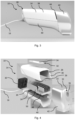
- the housing 28 provides a cover for the microwave source 20, the waveguide 22, the heat sink 24, the transmission line 26, and/or the fan 30. This means that the microwave source 20, the waveguide 22, the heat sink 24, the transmission line 26, and/or the fan 30 may be arranged within the housing 28.
- the waveguide cover 42 can be provided for covering the waveguide 22.
- the waveguide cover 42 may be solely attached to the waveguide 22 while the waveguide 22 is attached to the heatsink 24. Thus, the waveguide cover 42 may be not directly attached to the top shell 38 and/or the bottom shell 40.
- the top shell 38, the bottom shell, and the waveguide cover 42 optionally provide a continuous surface except of the control portion 32, vents 44 and/or a treatment aperture 46.
- the top shell 38, the bottom shell 40, and the waveguide cover 42 may be made from a plastic material.
- the housing 28 includes four vents 44.
- Two vents 44 are arranged on one side of the heatsink 24 while the other two vents 44 are arranged on the other side of the heatsink 24.
- two vents 44 can act as an air inlet while the other two vents 44 may act as an air outlet.
- the arrangement of the vents 44 at both sides of the heatsink 24 allows an airflow along the heatsink 24.
- the fan 30 may be provided proximate to the air inlet vents 44, in particular between the air inlet vents 44 and the heatsink 24.
- the far 30 is provided for generating the airflow along the heatsink 24.
- the fan 30 may be electrically connected to the power cable 16; the fan 30 can be powered by the power source 12.
- the heatsink 24 includes a base plate 48 and a plurality of fins 50.
- the fins 50 are provided for increasing the surface area of the heatsink 24 such that the heatsink 24 can be better cooled by the fan 30.
- the heatsink 24 may be made from a metal material.
- the fins 50 protrude from the base plate 48 and may be integrally formed with the base plate 48.
- the fins 50 may be arranged parallel to each other and/or perpendicular to the fan 30. The directions of extension of the fin 50 may extend from the air inlet vents 44 to the air outlet vents 44.
- the heatsink 24, in particular the base plate 48, may provide support for the microwave source 20 and/or the housing 28.
- the waveguide 22 may also be attached to the base plate 48.
- the microwave source 20 can be considered a generator for generating microwave energy.
- the microwave source 20 may provide microwave energy having a frequency of 14.5 GHz.
- the microwave source 20 may include one or more Gallium Nitride (GaN) microwave power transistors that can produce up to 25 W of power at 14.5 GHz.
- the microwave power transistors may be arranged on a circuit board which in turn is directly attached to the base plate 48 in order to effectively transmit heat generated by the microwave power transistors to the heatsink 24.
- GaN Gallium Nitride
- the microwave power transistors may be arranged on a circuit board which in turn is directly attached to the base plate 48 in order to effectively transmit heat generated by the microwave power transistors to the heatsink 24.
- a good transmission of thermal energy and effective cooling of the microwave source 20 is achieved if the microwave source 20 is directly attached to the heatsink 24.
- the microwave energy is transmitted from the microwave source 20 to the waveguide 22 by means of the transmission line 26.
- the transmission line 26 may be a coaxial cable such as a SMA (SubMiniature version A) cable.
- the microwave source 20 is directly attached to the waveguide 22 such that the transmission line 26 can be omitted.
- the cover 52 may be a disposable component which is newly used for each person treated with the skin treatment apparatus 10.
- the cover 52 may be a component that is capable of being sterilised according to the required sterilisation protocols.
- a cross-sectional area (e.g. inner and/or outer) of the first waveguide section 54 is smaller than a cross-sectional area (e.g. inner and/or outer) of the second waveguide section 56.
- both a width and a length of the rectangular cross-sectional area of the first waveguide section 54 are smaller than the corresponding width and length of the cross-sectional area of the second waveguide section 56.
- the tapered waveguide section 58 has an inner cross-sectional area which at least partially changes along its extension from the second waveguide section 56 to the first waveguide section 54.
- the inner cross-sectional area of the tapered waveguide section 58 gets smaller from the second waveguide section 56 to the first waveguide section 54.
- the tapered waveguide section 58 acts as an adapter between the first waveguide section 54 and the second waveguide section 56.
- the outer cross-sectional area may remain constant, for example, the outer cross-sectional area may be the same as that of the second waveguide section 56 as shown in Figs. 8 and 9 .
- the first waveguide section 54 includes the treatment aperture 46 and a meta surface structure 60 described in the following.
- the second waveguide section 56 may include a connector 62 which may be a connector for the SMA cable, for example the transmission line 26.
- An antenna 64 may be formed at the end of the transmission line 26 such that by attaching the transmission line 26 to the connector 62, the antenna 64 is arranged within the second waveguide section 56.
- the antenna 64 may be constituted by an inner conductor of the SMA cable whereby an outer conductor as well as a dielectric material acting as an insulator between the inner conductor and outer conductor is removed (see Fig. 9 ).
- the antenna 64 may form part of the connector 62, and so the antenna 64 may be detachably coupled to the transmission line 26 and/or held in a fixed position with respect to the second waveguide section 56.
- the antenna 64 emits microwave radiation which is guided by the waveguide 22 to the skin. The microwave radiation leaves the waveguide 22 at the treatment aperture 46.
- the second waveguide section 56 includes a regular waveguide section 66 and a matching waveguide section 68.
- the regular waveguide section 66 may be a commercially available waveguide such as a WR62 waveguide.
- the matching waveguide section 68 may have a length in the extension of the propagation of the microwave radiation which is chosen to minimise reflection of the microwave radiation at the tapered waveguide section 58.
- the first waveguide section 54, the second waveguide section 56, and/or the tapered waveguide section 58 includes an inner surface which is made from an electrically conductive material, such as metal.
- the waveguide body of the waveguide 22 is solely made from metal, such as copper.
- the waveguide 22 defines a cavity through which microwave radiation can propagate, in particular from the antenna 64 to the treatment aperture 46.
- the intensity of the electric field at the inner surface of the waveguide 22 depends on the orientation of the electric field with respect to the inner surface of the waveguide 22.
- the waveguide 22 can be dimensioned to carry the microwave frequency electromagnetic energy in a fundamental mode, which interacts with the boundary condition set up by the waveguide 22 such that the electromagnetic field emitted by the waveguide 22 is in a quasi-TEM mode.
- This means that the intensity of the electric field of the microwave radiation drops to zero at two opposing wall sections 70, namely if the electric field of the microwave radiation is parallel (or almost parallel) to the extension of the inner surface of the two opposing wall sections 70 of the waveguide 22.
- the intensity of the microwave radiation at the treatment aperture 46 is not spatially constant. This makes the treatment of the skin more complicated since the user of the skin treatment apparatus 10 needs to consider the spatially varying intensity of the microwave radiation.
- the meta surface structure 60 is provided at one or both of the two opposing wall sections 70.
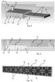
- the meta surface structure 60 is provided at the two opposing wall section 70 over the complete length of extension (which is parallel to the direction of propagation of the microwave radiation) of the first waveguide section 54.
- the meta surface structure 60 covers the complete width of the two opposing wall sections 70. Thus, the two opposing wall sections 70 are completely covered by the meta surface structure 60.
- the two opposing wall sections 70 may be considered as extending over the complete length of the first waveguide section 54 in the axial direction thereof.
- the meta surface structure 60 has the characteristics of a quasi-perfect magnetic conductor such that there is no drop of the electric field at the meta surface structure 60.
- the characteristics of the perfect magnetic conductor do not appear over the whole frequency range but do appear at a predetermined frequency band which preferably corresponds to the frequency of the microwave radiation.
- the meta surface structure 60 may be a microstrip having a nonconductive substrate 72 and a conductive layer 74 arranged on the nonconductive substrate 72.
- the conductive layer 74 forms a pattern whose shape and arrangement give rise to the quasi-perfect magnetic conductor characteristics.
- the pattern and, thus, the conductive layer 74 are made up (e.g. consists) of a plurality of identical unit cells 76.
- the plurality of unit cells 76 defines the pattern.
- Each unit cell 76 is defined by a (imaginary) border 78 whereby a section of the border 78 of one unit cell 76 coincides with a section of the border 78 of another unit cell 76.
- Each unit cell 76 comprises at least one capacitive portion 80, at least one inductive portion 82, and at least one intermediate portion 84.
- the capacitive portion 80 is connected to the inductive portion 82 by the intermediate portion 84 such that the capacitive portion 80, the inductive portion 82, and the intermediate portion 84 form an electric circuit.
- the capacitive portion 80 of one unit cell 76 forms a capacitor with a capacitive portion 80 of another unit cell 76. To this end, the capacitive portion 80 is spaced apart from the border 78 of the unit cell 76. Thus, there is a gap between the capacitive portion 80 of one unit cell 76 and the capacitive portion 80 of another unit cell 76. However, in an embodiment not shown in the figures, two capacitive portions 80 of one unit cell 76 form a capacitor.
- the inductive portion 82 extends up to the border 78 of the unit cell 76 such that the inductive portion 82 of one unit cell 76 is connected to the inductive portion 82 of another unit cell 76.
- two unit cells 76 are connected by their respective inductive portions 82.
- the inductive portion 82 is arranged between two capacitive portions 80 of one unit cell 76.
- the unit cell 76 and, in particular, the border 78 has a square shape.
- the unit cell 76 may include two axes of mirror symmetry 86 which are perpendicular to each other (see Fig. 12 ).
- the axes of mirror symmetry 86 extend along the direction of the inductive portions 82.
- the capacitive portion 80 has a square shape and the inductive portion 82 has a rectangular shape.
- the capacitive portions 80 are aligned with the edges of the border 78.
- four capacitive portions 80, four inductive portions 82, and one intermediate portion 84 are provided.
- the intermediate portion 84 may be considered as a square wherein each corner of the intermediate portion 84 contacts one corner of each capacitive portion 80.
- the intermediate portion 84 further includes rectangular stripe portions 88 which extend between two capacitive portions 80.
- each capacitive portion 80 is in contact with two stripe portions 88 of the intermediate portion 84.
- Each inductive portion 82 is in contact with a single stripe portion 88.
- the stripe portion 88 and the rectangle of the intermediate portion 84 may be a unitary component and are identified for describing the shape of the intermediate portion 84.
- the unit cells 76 are arranged in a row 90 (see Fig. 10 ).
- a plurality of rows 90 may be provided (see Figs. 7 and 11 ).
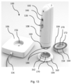
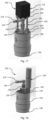
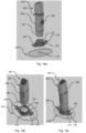
- Fig. 13 shows a skin treatment kit 100 which includes a handheld applicator 102, and applicator pad 104, and a base portion 106.
- the handheld applicator 102 may be the handpiece 14 as described above. It is also possible that the applicator 102 has the configuration as described below.
- the applicator 102 includes an applicator housing 108, a microwave emitter 110, and an actuator assembly 112.
- the applicator housing 108 is a means for supporting and shielding the microwave emitter 110, the actuator assembly 112 and/or further optional components of the handheld applicator 102.
- the applicator housing 108 may include one or more housing parts 114 and a support portion 116.
- the one or more housing parts 114 provide the outer surface of the applicator 102 similar to the housing 28 described above.
- the housing parts 114 may be attached to each other to form a smooth outer surface.
- Ventilation means such as a plurality of slits and/or through-holes may provided in the housing parts 114 for allowing air exchange between the inside of the applicator housing 108 and the surroundings of the applicator housing 108.
- the applicator housing 108 or the housing parts 114 may completely or partially cover the components arranged within the housing parts 114.
- the housing part 114 may be attached to the support portion 116 which can be a solid structure for supporting the microwave emitter 110 and/or the actuator assembly 112.
- the support portion 116 may act as a support to which the microwave emitter 110, the actuator assembly 112, and/or the housing parts 114 can be attached, for example by means of screws or other fasting means.
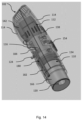
- the microwave emitter 110 may include a transmission line 118, a waveguide 120, and/or a tube 122.
- the transmission line 118 many include a flexible coaxial cable and/or a rigid coaxial transmission line.
- the transmission line 118 is configured to transmit microwave radiation from a connector 124 to the waveguide 120.
- the connector 124 may be configured to be permanently or releasably connected to a coaxial cable 126 which is connected to the base portion 106.
- the transmission line 118 is connected to an antenna (not shown in the figures) which is arranged within the waveguide 120 for emitting microwave radiation into the waveguide 120.
- the antenna and the part of the transmission line 118 connected to the waveguide 120 can be configured as the above-described antenna 64 and connector 62, respectively.
- the antenna may be spaced depart from a back surface of the waveguide 120 by a distance of ((2n-1)* ⁇ )/4, wherein ⁇ is wavelength of the microwave radiation and n is and integer equal to or greater than 0.
- the waveguide 120 can be a circular tube defining a rotatable axis 128 which may correspond to axis of symmetry of the waveguide 120.
- the rotatable axis 128 extends through a centre point of the waveguide 120.
- the waveguide 120 has an open end at which the microwave radiation propagating within the waveguide 120 is release to the outside of the applicator 102.
- the open end of the waveguide 120 may correspond to a distal end 130 of the applicator 102 and can include the characteristics, features and/or optional embodiments as the treatment aperture 46 described above.
- the tube 122 can be a circular tube defining a centre axis which may correspond to axis of symmetry of the tube 122.
- the centre axis may be a rotation axis 132 around which the waveguide 120 rotates.
- the centre axis or rotation axis 132 is parallel to the rotatable axis 128 and extends outside of the waveguide 120.
- the tube 122 is attached to the applicator housing 108, in particular the support portion 116, by means of a bearing 134 such that the tube 122 can be rotated with respect to the applicator housing 108, in particular around the rotation axis 132 or its centre axis.
- the actuator assembly rotates the rotatable axis 128 around the rotation axis 132.
- the waveguide 120 is attached to the tube 122.
- the dressing 178 may be attached to the skin prior to the treatment of the skin by microwave radiation.
- the dressing 178 may be arranged between the applicator pad 104 and the skin.
- the microwave radiation emitted by the handheld applicator 102 propagates through the dressing 178 and is absorbed by the skin. Therefore, the dressing 178 is made of a material which is transmissible to microwave radiation.
- the waveguide 120 intrinsically emits microwave radiation which has an intensity profile which is not uniform in a plane of the treatment aperture of the waveguide 120. This results in that that the skin to be treated with the microwave radiation is not uniformly heated.
- the waveguide 120 is moved.
- the waveguide 120 is rotated around the rotation axis 132, for example two times.
- the waveguide 120 has a movement pattern which defines a ring. The outer perimeter of this ring may correspond to the outer perimeter of the target area.
- An area of the target area which coincides with the middle of this ring may not be subjected to microwave radiation. However, this area is heated due to the thermal conductivity of the skin. What is more, the inventors surprisingly found that the above-described movement pattern of the waveguide 120 produces an area of uniform heating of the skin despite the fact that the target area is not uniformly subjected to microwave radiation.
- the controller may start a microwave treatment routine after receiving a start signal from an input device 186 which may be a button or switch arranged on the applicator 102.
- the microwave treatment routine may include rotating the waveguide 120 a complete rotation around the rotation axis 132 without generating microwave radiation. This is done to check whether the gear mechanism 140 and/or the motor 138 are jammed or not. After that, the microwave treatment routine may include two complete rotations of the waveguide 120 around the rotation axis 132 during which microwave radiation is generated.
- the microwave treatment routine may only be started when the safety signal is received, or microwave radiation is only generated when the safety signal is received.
Landscapes
- Health & Medical Sciences (AREA)
- Engineering & Computer Science (AREA)
- Biomedical Technology (AREA)
- Life Sciences & Earth Sciences (AREA)
- Public Health (AREA)
- Veterinary Medicine (AREA)
- Nuclear Medicine, Radiotherapy & Molecular Imaging (AREA)
- Animal Behavior & Ethology (AREA)
- General Health & Medical Sciences (AREA)
- Radiology & Medical Imaging (AREA)
- Pathology (AREA)
- Surgery (AREA)
- Physics & Mathematics (AREA)
- Electromagnetism (AREA)
- Otolaryngology (AREA)
- Heart & Thoracic Surgery (AREA)
- Medical Informatics (AREA)
- Molecular Biology (AREA)
- Oral & Maxillofacial Surgery (AREA)
- Plastic & Reconstructive Surgery (AREA)
- Radiation-Therapy Devices (AREA)
Claims (14)
- Handapplikator zur Behandlung von Haut mit Mikrowellenstrahlung, der Folgendes umfasst:ein Applikatorgehäuse (108) undeinen Mikrowellenstrahler (110), der ausgelegt ist, um Mikrowellenstrahlung für die Behandlung von Gewebe in einem Zielbereich zu emittieren, gekennzeichnet durcheine Aktuatoranordnung (112), die ausgelegt ist, um den Mikrowellenstrahler (110) in Bezug auf das Applikatorgehäuse (108) zu bewegen, während Mikrowellenstrahlung emittiert wird, um die Gleichförmigkeit der Gewebebehandlung im Zielbereich zu erhöhen.
- Handapplikator nach Anspruch 1, wobei der Mikrowellenstrahler (110) einen Wellenleiter (120) umfasst, wobei die Aktuatoranordnung (112) ausgelegt ist, um den Wellenleiter (120) zu bewegen, wobei der Wellenleiter (120) gegebenenfalls in einer Querschnittsansicht des Wellenleiters (120) kreisförmig ist.
- Handapplikator nach Anspruch 1 oder 2, wobei die Aktuatoranordnung (112) ausgelegt ist, um den Mikrowellenstrahler (110) um eine Rotationsachse (132) zu rotieren.
- Handapplikator nach Anspruch 3, wobei in einer Querschnittsansicht des Applikators (102) der Mittelpunkt des Wellenleiters (120) zur Rotationsachse (132) versetzt ist, wobei gegebenenfalls in einer Querschnittsansicht des Applikators (102) der komplette Wellenleiter (120) zur Mittelachse versetzt ist.
- Handapplikator nach einem der Ansprüche 2 bis 4, wobei der Mikrowellenstrahler (110) weiters ein Rohr (122) umfasst, wobei der Wellenleiter (120) versetzt zur Mittelachse des Rohrs (122) angeordnet ist, wobei die Aktuatoranordnung (112) gegebenenfalls ausgelegt ist, um das Rohr (122) um seine Mittelachse zu rotieren.
- Handapplikator nach Anspruch 5, wobei der Mikrowellenstrahler (110) einen rotierbaren Anschluss(136) für eine koaxiale Übertragungsleitung umfasst, wobei der rotierbare Anschluss (136) gegebenenfalls auf der Mittelachse angeordnet ist.
- Hautbehandlungsset, das Folgendes umfasst:einen Handapplikator (102) nach einem der Ansprüche 1 bis 6 undeine Applikator-Auflage (104) für den Handapplikator (102), wobei die Applikator-Auflage (104) Folgendes umfasst:einen ersten Abschnitt (158), der ausgelegt ist, um auf der Haut angebracht zu werden,einen zweiten Abschnitt (160) entgegengesetzt zum ersten Abschnitt (158) zur Aufnahme des Applikators (102),wobei der zweite Abschnitt (160) eine Halterung (162) umfasst, die ausgelegt ist, um einen Einführungsabschnitt (164) des Applikators (102) aufzunehmen, um den Applikator (102) zu stützen.
- Hautbehandlungsset nach Anspruch 7, wobei die Halterung (162) aus einem steifen Material besteht, wobei gegebenenfalls die gesamte Applikator-Auflage (104) aus einem steifen Material besteht.
- Hautbehandlungsset nach Anspruch 7 oder 8, das weiters eine Kappe (170) umfasst, die für elektromagnetische Strahlung im sichtbaren Spektrum und Mikrowellenspektrum durchlässig ist, wobei die Kappe (170) am ersten Abschnitt (158) angeordnet ist, wobei die Halterung (162) gegebenenfalls so geformt ist, das der Einführungsabschnitt (164) des Applikators (102) an die Kappe (170) anstoßen kann.
- Hautbehandlungsset nach einem der Ansprüche 7 bis 9, das weiters einen Verband (178) umfasst, der für elektromagnetische Strahlung im sichtbaren Spektrum und Mikrowellenspektrum durchlässig ist und ausgelegt ist, um zwischen der Haut und der Applikator-Auflage (104) platziert zu werden.
- Hautbehandlungsset nach Anspruch 9 oder 10, wobei die Kappe (170) und/oder der Verband (178) eine sichtbare Markierung (172) umfassen, die einen Zielbereich anzeigt.
- Hautbehandlungsset nach einem der Ansprüche 7 bis 11, wobei der Applikator (102) den Einführungsabschnitt (164) umfasst, wobei der Einführungsabschnitt (164) ausgelegt ist, um eng in der Halterung (162) aufgenommen zu werden.
- Hautbehandlungsset nach einem der Ansprüche 7 bis 12, das weiters ein Verriegelungsmittel (188) umfasst, um den Einführungsabschnitt (164) in der Halterung (162) zu verriegeln.
- Hautbehandlungsset nach einem der Ansprüche 7 bis 12, wobei der Applikator (102) ein Sicherheitsmittel (180) umfasst, das ausgelegt ist, um ein Sicherheitssignal auszugeben, wenn der Einführungsabschnitt (164) korrekt in der Halterung (162) positioniert ist, wobei der Mikrowellenstrahler (110) gegebenenfalls nur Mikrowellenstrahlung aussendet, wenn er das Sicherheitssignal empfängt.
Applications Claiming Priority (2)
| Application Number | Priority Date | Filing Date | Title |
|---|---|---|---|
| GBGB2110955.8A GB202110955D0 (en) | 2021-07-29 | 2021-07-29 | Waveguide section, waveguide, skin treatment apparatus, handheld applicator, applicator pad and a skin treatment kit |
| PCT/EP2022/070713 WO2023006633A1 (en) | 2021-07-29 | 2022-07-22 | Waveguide section, waveguide, skin treatment apparatus, handheld applicator, applicator pad and a skin treatment kit |
Publications (3)
| Publication Number | Publication Date |
|---|---|
| EP4376940A1 EP4376940A1 (de) | 2024-06-05 |
| EP4376940C0 EP4376940C0 (de) | 2025-07-09 |
| EP4376940B1 true EP4376940B1 (de) | 2025-07-09 |
Family
ID=77651332
Family Applications (1)
| Application Number | Title | Priority Date | Filing Date |
|---|---|---|---|
| EP22754402.0A Active EP4376940B1 (de) | 2021-07-29 | 2022-07-22 | Tragbarer applikator und hautbehandlungskit |
Country Status (5)
| Country | Link |
|---|---|
| US (1) | US20250073483A1 (de) |
| EP (1) | EP4376940B1 (de) |
| AU (1) | AU2022320863A1 (de) |
| GB (1) | GB202110955D0 (de) |
| WO (1) | WO2023006633A1 (de) |
Family Cites Families (9)
| Publication number | Priority date | Publication date | Assignee | Title |
|---|---|---|---|---|
| EP2032064A2 (de) * | 2006-06-27 | 2009-03-11 | Palomar Medical Technologies, Inc. | Tragbares photkosmetisches gerät |
| ES2488565T3 (es) * | 2007-04-19 | 2014-08-27 | Miramar Labs, Inc. | Dispositivos y sistemas para la distribución no invasiva de terapia de microondas |
| PT2211916E (pt) * | 2007-11-06 | 2016-01-11 | Creo Medical Ltd | Sistema de esterilização por plasma de micro-ondas e respetivos aplicadores |
| GB2467604B (en) * | 2009-02-10 | 2013-08-28 | Univ Bangor | Skin treatment apparatus and method |
| US9314301B2 (en) * | 2011-08-01 | 2016-04-19 | Miramar Labs, Inc. | Applicator and tissue interface module for dermatological device |
| WO2014168832A1 (en) * | 2013-04-08 | 2014-10-16 | Farhan Taghizadeh | System and method for providing treatment feedback for a thermal treatment device |
| US10779885B2 (en) * | 2013-07-24 | 2020-09-22 | Miradry. Inc. | Apparatus and methods for the treatment of tissue using microwave energy |
| GB2555071A (en) * | 2016-05-24 | 2018-04-25 | Bangor Univ | Skin treatment apparatus |
| KR20200131709A (ko) * | 2019-05-14 | 2020-11-24 | 박영철 | 마이크로파 온열치료기 |
-
2021
- 2021-07-29 GB GBGB2110955.8A patent/GB202110955D0/en not_active Ceased
-
2022
- 2022-07-22 WO PCT/EP2022/070713 patent/WO2023006633A1/en not_active Ceased
- 2022-07-22 EP EP22754402.0A patent/EP4376940B1/de active Active
- 2022-07-22 US US18/292,378 patent/US20250073483A1/en active Pending
- 2022-07-22 AU AU2022320863A patent/AU2022320863A1/en active Pending
Also Published As
| Publication number | Publication date |
|---|---|
| US20250073483A1 (en) | 2025-03-06 |
| EP4376940C0 (de) | 2025-07-09 |
| AU2022320863A1 (en) | 2024-01-04 |
| EP4376940A1 (de) | 2024-06-05 |
| WO2023006633A1 (en) | 2023-02-02 |
| GB202110955D0 (en) | 2021-09-15 |
Similar Documents
| Publication | Publication Date | Title |
|---|---|---|
| EP3463139B1 (de) | Hautbehandlungsvorrichtung | |
| EP2345454B1 (de) | Ablationsvorrichtung mit Benutzerschnittstelle am Vorrichtungsgriff und System mit der Ablationsvorrichtung | |
| JP6464230B2 (ja) | 柔軟な流体冷却シャフトを備えたエネルギー伝達装置、それと共に使用するのに適した流入/流出接合部およびそれらを含むシステム | |
| JP6392389B2 (ja) | 柔軟な流体冷却シャフトを備えたエネルギー伝達装置、それと共に使用するのに適した流入/流出接合部およびそれらを含むシステム | |
| US10779885B2 (en) | Apparatus and methods for the treatment of tissue using microwave energy | |
| JP6195694B2 (ja) | 柔軟な流体冷却シャフトを備えたエネルギー伝達装置、それと共に使用するのに適した流入/流出接合部およびそれらを含むシステム | |
| US6463336B1 (en) | Active bandage suitable for applying pulsed radio-frequencies or microwaves to the skin for medical purposes | |
| JP6072409B2 (ja) | 柔軟な流体冷却シャフトを備えたエネルギー伝達装置、それと共に使用するのに適した流入/流出接合部およびそれらを含むシステム | |
| JP6104508B2 (ja) | 超音波トランスデューサアレイおよび位相アンテナアレイを含むエネルギー伝達装置 | |
| US20190299017A1 (en) | Systems and methods for targeted deep hyperthermia by time-shared rf inductive applicators | |
| CA2440139A1 (en) | Method of breaking cancer cell tissue by microelectromagnetic radiation and microelectromagnetic radiator | |
| US20250073483A1 (en) | Waveguide section, waveguide, skin treatment apparatus, handheld applicator, applicator pad and a skin treatment kit | |
| KR102677532B1 (ko) | 피부 화상 방지를 위한 의료기기용 핸드피스 및 제어방법 | |
| WO2021197643A1 (en) | A device for elimination of a pathogen | |
| Nikawa et al. | Heating system with a lens applicator for 430 MHz microwave hyperthermia | |
| CN218851940U (zh) | 气溶胶生成装置 | |
| KR20200035843A (ko) | 플라즈마 발생 장치 | |
| RU2112566C1 (ru) | Аппарат для квч-терапии (варианты) | |
| KR20250168097A (ko) | 마이크로파-기반 비침습적 피부 타이트닝 시스템들 및 방법들 |
Legal Events
| Date | Code | Title | Description |
|---|---|---|---|
| STAA | Information on the status of an ep patent application or granted ep patent |
Free format text: STATUS: UNKNOWN |
|
| STAA | Information on the status of an ep patent application or granted ep patent |
Free format text: STATUS: THE INTERNATIONAL PUBLICATION HAS BEEN MADE |
|
| PUAI | Public reference made under article 153(3) epc to a published international application that has entered the european phase |
Free format text: ORIGINAL CODE: 0009012 |
|
| STAA | Information on the status of an ep patent application or granted ep patent |
Free format text: STATUS: REQUEST FOR EXAMINATION WAS MADE |
|
| 17P | Request for examination filed |
Effective date: 20231212 |
|
| AK | Designated contracting states |
Kind code of ref document: A1 Designated state(s): AL AT BE BG CH CY CZ DE DK EE ES FI FR GB GR HR HU IE IS IT LI LT LU LV MC MK MT NL NO PL PT RO RS SE SI SK SM TR |
|
| DAV | Request for validation of the european patent (deleted) | ||
| DAX | Request for extension of the european patent (deleted) | ||
| GRAP | Despatch of communication of intention to grant a patent |
Free format text: ORIGINAL CODE: EPIDOSNIGR1 |
|
| STAA | Information on the status of an ep patent application or granted ep patent |
Free format text: STATUS: GRANT OF PATENT IS INTENDED |
|
| RIC1 | Information provided on ipc code assigned before grant |
Ipc: A61N 5/04 20060101ALI20250127BHEP Ipc: A61B 18/00 20060101ALI20250127BHEP Ipc: A61B 18/18 20060101ALI20250127BHEP Ipc: A61N 5/02 20060101ALI20250127BHEP Ipc: A61N 1/32 20060101AFI20250127BHEP |
|
| INTG | Intention to grant announced |
Effective date: 20250206 |
|
| GRAS | Grant fee paid |
Free format text: ORIGINAL CODE: EPIDOSNIGR3 |
|
| GRAA | (expected) grant |
Free format text: ORIGINAL CODE: 0009210 |
|
| STAA | Information on the status of an ep patent application or granted ep patent |
Free format text: STATUS: THE PATENT HAS BEEN GRANTED |
|
| AK | Designated contracting states |
Kind code of ref document: B1 Designated state(s): AL AT BE BG CH CY CZ DE DK EE ES FI FR GB GR HR HU IE IS IT LI LT LU LV MC MK MT NL NO PL PT RO RS SE SI SK SM TR |
|
| REG | Reference to a national code |
Ref country code: GB Ref legal event code: FG4D |
|
| REG | Reference to a national code |
Ref country code: CH Ref legal event code: EP |
|
| REG | Reference to a national code |
Ref country code: IE Ref legal event code: FG4D |
|
| REG | Reference to a national code |
Ref country code: DE Ref legal event code: R096 Ref document number: 602022017387 Country of ref document: DE |
|
| U01 | Request for unitary effect filed |
Effective date: 20250806 |
|
| U07 | Unitary effect registered |
Designated state(s): AT BE BG DE DK EE FI FR IT LT LU LV MT NL PT RO SE SI Effective date: 20250819 |
|
| U20 | Renewal fee for the european patent with unitary effect paid |
Year of fee payment: 4 Effective date: 20251117 |
|
| PG25 | Lapsed in a contracting state [announced via postgrant information from national office to epo] |
Ref country code: IS Free format text: LAPSE BECAUSE OF FAILURE TO SUBMIT A TRANSLATION OF THE DESCRIPTION OR TO PAY THE FEE WITHIN THE PRESCRIBED TIME-LIMIT Effective date: 20251109 |
|
| PG25 | Lapsed in a contracting state [announced via postgrant information from national office to epo] |
Ref country code: NO Free format text: LAPSE BECAUSE OF FAILURE TO SUBMIT A TRANSLATION OF THE DESCRIPTION OR TO PAY THE FEE WITHIN THE PRESCRIBED TIME-LIMIT Effective date: 20251009 |
|
| PG25 | Lapsed in a contracting state [announced via postgrant information from national office to epo] |
Ref country code: HR Free format text: LAPSE BECAUSE OF FAILURE TO SUBMIT A TRANSLATION OF THE DESCRIPTION OR TO PAY THE FEE WITHIN THE PRESCRIBED TIME-LIMIT Effective date: 20250709 |
|
| PG25 | Lapsed in a contracting state [announced via postgrant information from national office to epo] |
Ref country code: GR Free format text: LAPSE BECAUSE OF FAILURE TO SUBMIT A TRANSLATION OF THE DESCRIPTION OR TO PAY THE FEE WITHIN THE PRESCRIBED TIME-LIMIT Effective date: 20251010 |
|
| PG25 | Lapsed in a contracting state [announced via postgrant information from national office to epo] |
Ref country code: PL Free format text: LAPSE BECAUSE OF FAILURE TO SUBMIT A TRANSLATION OF THE DESCRIPTION OR TO PAY THE FEE WITHIN THE PRESCRIBED TIME-LIMIT Effective date: 20250709 |
|
| PG25 | Lapsed in a contracting state [announced via postgrant information from national office to epo] |
Ref country code: RS Free format text: LAPSE BECAUSE OF FAILURE TO SUBMIT A TRANSLATION OF THE DESCRIPTION OR TO PAY THE FEE WITHIN THE PRESCRIBED TIME-LIMIT Effective date: 20251009 |
|
| PG25 | Lapsed in a contracting state [announced via postgrant information from national office to epo] |
Ref country code: ES Free format text: LAPSE BECAUSE OF FAILURE TO SUBMIT A TRANSLATION OF THE DESCRIPTION OR TO PAY THE FEE WITHIN THE PRESCRIBED TIME-LIMIT Effective date: 20250709 |
|
| REG | Reference to a national code |
Ref country code: CH Ref legal event code: H13 Free format text: ST27 STATUS EVENT CODE: U-0-0-H10-H13 (AS PROVIDED BY THE NATIONAL OFFICE) Effective date: 20260224 |
|
| PG25 | Lapsed in a contracting state [announced via postgrant information from national office to epo] |
Ref country code: SM Free format text: LAPSE BECAUSE OF FAILURE TO SUBMIT A TRANSLATION OF THE DESCRIPTION OR TO PAY THE FEE WITHIN THE PRESCRIBED TIME-LIMIT Effective date: 20250709 |
|
| PGFP | Annual fee paid to national office [announced via postgrant information from national office to epo] |
Ref country code: AT Payment date: 20260410 Year of fee payment: 4 |
|
| PG25 | Lapsed in a contracting state [announced via postgrant information from national office to epo] |
Ref country code: CZ Free format text: LAPSE BECAUSE OF FAILURE TO SUBMIT A TRANSLATION OF THE DESCRIPTION OR TO PAY THE FEE WITHIN THE PRESCRIBED TIME-LIMIT Effective date: 20250709 Ref country code: CH Free format text: LAPSE BECAUSE OF NON-PAYMENT OF DUE FEES Effective date: 20250731 |
|
| PG25 | Lapsed in a contracting state [announced via postgrant information from national office to epo] |
Ref country code: SK Free format text: LAPSE BECAUSE OF FAILURE TO SUBMIT A TRANSLATION OF THE DESCRIPTION OR TO PAY THE FEE WITHIN THE PRESCRIBED TIME-LIMIT Effective date: 20250709 |
|
| PLBE | No opposition filed within time limit |
Free format text: ORIGINAL CODE: 0009261 |
|
| STAA | Information on the status of an ep patent application or granted ep patent |
Free format text: STATUS: NO OPPOSITION FILED WITHIN TIME LIMIT |