EP4376540A2 - Verfahren zur aktivierung oder deaktivierung einer verbindung auf benutzerebene pro sitzung - Google Patents
Verfahren zur aktivierung oder deaktivierung einer verbindung auf benutzerebene pro sitzung Download PDFInfo
- Publication number
- EP4376540A2 EP4376540A2 EP23213830.5A EP23213830A EP4376540A2 EP 4376540 A2 EP4376540 A2 EP 4376540A2 EP 23213830 A EP23213830 A EP 23213830A EP 4376540 A2 EP4376540 A2 EP 4376540A2
- Authority
- EP
- European Patent Office
- Prior art keywords
- session
- node
- core network
- network node
- smf
- Prior art date
- Legal status (The legal status is an assumption and is not a legal conclusion. Google has not performed a legal analysis and makes no representation as to the accuracy of the status listed.)
- Pending
Links
Images






Classifications
-
- H—ELECTRICITY
- H04—ELECTRIC COMMUNICATION TECHNIQUE
- H04W—WIRELESS COMMUNICATION NETWORKS
- H04W80/00—Wireless network protocols or protocol adaptations to wireless operation
- H04W80/08—Upper layer protocols
- H04W80/10—Upper layer protocols adapted for application session management, e.g. SIP [Session Initiation Protocol]
-
- H—ELECTRICITY
- H04—ELECTRIC COMMUNICATION TECHNIQUE
- H04L—TRANSMISSION OF DIGITAL INFORMATION, e.g. TELEGRAPHIC COMMUNICATION
- H04L5/00—Arrangements affording multiple use of the transmission path
- H04L5/0091—Signalling for the administration of the divided path, e.g. signalling of configuration information
- H04L5/0096—Indication of changes in allocation
- H04L5/0098—Signalling of the activation or deactivation of component carriers, subcarriers or frequency bands
-
- H—ELECTRICITY
- H04—ELECTRIC COMMUNICATION TECHNIQUE
- H04W—WIRELESS COMMUNICATION NETWORKS
- H04W76/00—Connection management
- H04W76/10—Connection setup
- H04W76/12—Setup of transport tunnels
-
- H—ELECTRICITY
- H04—ELECTRIC COMMUNICATION TECHNIQUE
- H04W—WIRELESS COMMUNICATION NETWORKS
- H04W48/00—Access restriction; Network selection; Access point selection
- H04W48/18—Selecting a network or a communication service
-
- H—ELECTRICITY
- H04—ELECTRIC COMMUNICATION TECHNIQUE
- H04W—WIRELESS COMMUNICATION NETWORKS
- H04W76/00—Connection management
-
- H—ELECTRICITY
- H04—ELECTRIC COMMUNICATION TECHNIQUE
- H04W—WIRELESS COMMUNICATION NETWORKS
- H04W76/00—Connection management
- H04W76/10—Connection setup
- H04W76/11—Allocation or use of connection identifiers
-
- H—ELECTRICITY
- H04—ELECTRIC COMMUNICATION TECHNIQUE
- H04W—WIRELESS COMMUNICATION NETWORKS
- H04W76/00—Connection management
- H04W76/20—Manipulation of established connections
- H04W76/22—Manipulation of transport tunnels
-
- H—ELECTRICITY
- H04—ELECTRIC COMMUNICATION TECHNIQUE
- H04W—WIRELESS COMMUNICATION NETWORKS
- H04W76/00—Connection management
- H04W76/20—Manipulation of established connections
- H04W76/27—Transitions between radio resource control [RRC] states
-
- H—ELECTRICITY
- H04—ELECTRIC COMMUNICATION TECHNIQUE
- H04W—WIRELESS COMMUNICATION NETWORKS
- H04W76/00—Connection management
- H04W76/30—Connection release
- H04W76/32—Release of transport tunnels
-
- H—ELECTRICITY
- H04—ELECTRIC COMMUNICATION TECHNIQUE
- H04W—WIRELESS COMMUNICATION NETWORKS
- H04W76/00—Connection management
- H04W76/30—Connection release
- H04W76/38—Connection release triggered by timers
-
- H—ELECTRICITY
- H04—ELECTRIC COMMUNICATION TECHNIQUE
- H04W—WIRELESS COMMUNICATION NETWORKS
- H04W8/00—Network data management
- H04W8/02—Processing of mobility data, e.g. registration information at HLR [Home Location Register] or VLR [Visitor Location Register]; Transfer of mobility data, e.g. between HLR, VLR or external networks
- H04W8/08—Mobility data transfer
-
- H—ELECTRICITY
- H04—ELECTRIC COMMUNICATION TECHNIQUE
- H04W—WIRELESS COMMUNICATION NETWORKS
- H04W88/00—Devices specially adapted for wireless communication networks, e.g. terminals, base stations or access point devices
- H04W88/14—Backbone network devices
-
- H—ELECTRICITY
- H04—ELECTRIC COMMUNICATION TECHNIQUE
- H04W—WIRELESS COMMUNICATION NETWORKS
- H04W92/00—Interfaces specially adapted for wireless communication networks
- H04W92/16—Interfaces between hierarchically similar devices
- H04W92/24—Interfaces between hierarchically similar devices between backbone network devices
Definitions
- the present disclosure relates to a communication system.
- the disclosure has particular but not exclusive relevance to wireless communication systems and devices thereof operating according to the 3rd Generation Partnership Project (3GPP) standards or equivalents or derivatives thereof.
- 3GPP 3rd Generation Partnership Project
- the disclosure has particular although not exclusive relevance to the so-called ⁇ Next Generation' systems.
- the disclosure includes a method for independent activation or deactivation of user plane connection per Protocol Data Unit (PDU) session or network slice, where the session contexts in a User Equipment (UE) and in a network (e.g. a Session Management Function (SMF), and a User Plane Function (UPF)) are already established.
- a network e.g. a Session Management Function (SMF), and a User Plane Function (UPF)
- the solution proposes a (Session Management (SM)) state machine for each established PDU session, where the state machine is maintained either in the SMF or in a Mobility Management Function (MMF) network function.
- the SM state machines run independently of a Mobility Management (MM) state machine.
- GSM Global System of Mobile communications
- UMTS Universal Mobile Telecommunication System
- 4G Long Term Evolution (LTE)/Evolved Packet Core (EPC)
- 5G New Radio (NR)/NextGen
- GSM Global System of Mobile communications
- UMTS Universal Mobile Telecommunication System
- 4G Long Term Evolution (LTE)/Evolved Packet Core
- 5G New Radio (NR)/NextGen
- UE User Equipment
- serving node it can be any generation of the UE or the serving node.
- the terms 'serving node', ⁇ Mobility Management Entity (MME)/Serving General Packet Radio Service (GPRS) Support Node (SGSN)', ⁇ Mobile Switching Centre (MSC)/SGSN/MME', or Cellular Internet of Things (CIoT) Serving Gateway Node (C-SGN) is generally used through the various embodiments of this document to describe a functional entity like the MSC, the SGSN, the MME, the C-SGN, or other possible control plane functional entities in the mobile network which terminate a control plane signalling (known as a Non Access Stratum (NAS) signalling) between a core network and a terminal.
- the serving node (MME/SGSN) can be also a functional entity from future generation networks which is responsible for mobility and session management.
- HSS Home Subscriber Server
- HLR Home Location Register
- UDM Next Generation User Data Management
- SDM Subscriber Database Management
- AAA Authentication Authorization Accounting
- 'terminal', 'device', ⁇ user terminal', ⁇ User Equipment (UE)', or ⁇ Mobile Terminal (MT)' are used in an inter-exchangeable manner where all of the terms express similarly an equipment used to send/receive data and signalling from the network, a mobile network, or a radio access network.
- the term "session” is used in the same meaning as a "PDU session”, a "Packet Data Network (PDN) connection", an “Access Point Name (APN) connection", or a "connection for a particular network slice”.
- the existing sessions are those sessions for which already UE context exists (is established) in the core network control plane and/ or user plane and the UE itself.
- the "existing sessions” has the same meaning as an "established PDU session” or an "established PDN connection”.
- Each session can be identified with a "session ID”, which can be similar to an “Evolved Packet System (EPS) bearer ID", the "APN”, a “slice ID”, a “slice instance ID”, a “service ID” or any other temporary or a permanent identifier of the PDN connection, the PDU session or a service used by the UE.
- EPS Evolved Packet System
- connection is mostly used for user plane connection where a kind of "path” is established to send uplink (UL) or downlink (DL) data between the UE and a user plane Gateway (GW) terminating the PDU session.
- a connection can be either the whole user plane path for the PDU session; or only a connection over a given interface, e.g. connection over a radio interface, or connection over NG3 interface (between the UPF in a next generation core network (NG CN) and a (Radio) Access Network ((R)AN).
- NG CN next generation core network
- R Radio Access Network
- the mobility states of the UE are called De-Registered, Registered-Standby ("Standby” for simplicity) and Registered-Ready ("Ready” for simplicity). These states are also called MM states. Please note that there is a difference between the mobility states (the MM states) and session states (SM states).
- 5G 5th generation
- Activities in multiple research and standardization organizations were initiated to develop the 5G network which shall offer services to multiple vertical service providers and serving high variety of terminals.
- 3GPP in activities were initiated in the RAN area under the term "New Radio" (NR) and in the core network (CN) under the term “NextGen” (NG).
- NR New Radio
- CN core network
- NextGen NextGen
- Figure 1 describes the NG architecture for simultaneous access to multiple PDN connections (called PDU sessions in the NG study), as agreed in [see, NPL 1] by the time of writing.
- the upper part of Figure 1 shows an example for NG control plane (NG CP) including a subscriber database management (SDM) 22, a Policy Control function (PCF) 24 and Core Control functions (CCFs) 26.
- the NG CCF 26 includes among others mobility management function (MMF) and session management function (SMF).
- MMF mobility management function
- SMF session management function
- the user plane (UP) function(s) are shows as a Core User plane function (NG UPF) 28, as there could be one or multiple UPFs per PDU session configured. Further information about the description of the interfaces and the network functions can be found in TR 23.799 clause 7.3 [see, NPL 1].
- the 5G NG system can be "sliced" in multiple network instances which are referred as network slice instances (NSI).
- NSI network slice instances
- the network slices can be referred as logically separated networks where the resources (processing, storage and networking resources) for different network slices are isolated.
- a network operator uses a Network Slice Template/Blueprint to create a NSI.
- the NSI provides the network characteristics which are required by a Service Instance.
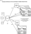
- Figure 2 One example of network architecture allowing a UE to connect to multiple NSIs simultaneously is shown in Figure 2 , as described in [see, NPL 1].
- Figure 2 shows a first network slice type/category (e.g. for IoT services) and a second slice type (e.g. for broadband services).
- the second network slice type can have multiple NSIs for particular 3rd party customers.
- This figure shows that the (R)AN is shared and network slicing is applied in the NG CN. However, in future also network slicing the (R)AN is possible where the RAN resources are sliced/isolated, either in baseband processing or in frequency spectrum or both.
- NPL 1 also describes the Common Control Network Functions (CCNF) 32 and Slice-specific Control Plane Network Functions (SCNF), as shown in detail in Figure 3 .
- the CCNF 32 can include fundamental control plane network functions to support basic functions operation common among the NSIs, for example:
- the NG system design should enable the transmission of any kind of data. It is assumed that the NG system supports the following PDU session types:
- the UE 34 may establish multiple PDU Sessions to the same data network in order to satisfy different connectivity requirements of different applications (e.g. session continuity) that require connectivity to the same data network.
- the MM and SM functions are separated.
- one main concept is that multiple SM contexts can be available per MM context.
- different session continuity types per PDU session are possible.
- NPL 1 3GPP TR 23.799 v0.6.0, 2016-07, "Study on Architecture for Next Generation System”
- NPL 2 3GPP TS 23.401, v14.0.0, 2016-06, "General Packet Radio Service (GPRS) enhancements for Evolved Universal Terrestrial Radio Access Network (E-UTRAN) access "
- GPRS General Packet Radio Service
- a UE is attached to the network and can be associated with multiple UP-GWs (UPFs).
- the different UPFs can be part of the (a) same PDU session, (b) part of different PDU sessions, or (3) part of different network slice instances (NSIs).
- NSS network slice instances
- a UE's "session” (or also called “PDN connection” or “PDU session” to a particular data network) can be in Idle (inactive) state or Active (connected) state. In this sense the terms “Idle session” or “Active session” are used. If a session is in "IDLE” state, then there is no NG3 connection/ tunnel established between the UPF and (R)AN. If a session is in "ACTIVE” state, then there is NG3 connection/tunnel established between the UPF and (R)AN.
- Session Management Function (SMF) is instantiated/configured in the control plane and corresponding one or more UPFs are instantiated/configured in the user plane. Further details about the IDLE and ACTIVE session state of the Control Plane Function (CPF) and the UPF can be found below.
- CPF Control Plane Function
- a mobility management mechanism maintains MM state always in Ready state in the NG core network (CN) as long as the UE is attached/ registered to the NG system.
- the NG CN has only Registered and Deregistered mobility states of the UE.
- This MM mechanism is advantageous for paging of mainly stationary devices or low-mobility devices for which the paging area is relatively narrow.
- the NG CN knows the location of the UE and the NG3 tunnels are always active. This means that the Session state is always "Active”. This document also targets to solve a potential problem in case such devices have another application which is configured to access with a different session at the same time.
- the NG CN performs session management while the (R)AN performs mobility management.
- all NG3 connections/tunnels for all sessions are always established, i.e. all sessions are always in Active session state.
- the UE moves and changes (R)AN node, all tunnels needs to be updated, meaning that the CCNF and the SMFs needs to update all UPFs with the new tunnel endpoint information. This would result in increased signalling.
- This disclosure seeks to solve or at least alleviate the above problems by reducing the required signalling for NG3 tunnel establishment allowing the activation of a particular session out of multiple existing sessions.
- An example aspect of the present disclosure is a User Equipment (UE), including: a transmitter configured to transmit at least one Protocol Data Unit (PDU) session identifier (ID), each of which indicates a PDU session that the UE needs to use in a Non Access Stratum (NAS) Service Request message to a Mobility Management Function (MMF) via an access network (AN) node when the UE has user data to send.
- PDU Protocol Data Unit
- ID IP address
- MMF Mobility Management Function
- Idle session or Active session are used for the SM states, whereas Standby and Ready states are used for the UE's mobility states.
- the transition from Idle session state to Active session state can be called “session activation” whereas the transition from Active session state to Idle session state can be called “session deactivation”. This is shown in Figure 6 .
- session activation procedure or “session deactivation” procedure relates to the establishment or release of NG3 connections/tunnels. These terms are different from “session establishment” or “session release” procedures which relates to the establishment of a new session including establishment of SM context in both UE and NG CN or correspondingly deletion of existing session, i.e. deletion of the SM context in the UE and the NG CN.
- each PDU session or network slice can have independent dedicated CPFs.
- the Dedicated CPFs can include the following exemplary network functionality:
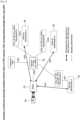
- the UE 34 is shown in Figure 5 by having 3 arrows towards the (R)AN node 30 which represents 3 radio connections corresponding to the 3 sessions/ slices A, B and C.
- the UE 34 can have e.g. 3 user plane radio connections (each per session) and just a single control plane radio connection.
- the UE 34 can have 3 user plane radio connections and 3 control plane radio connection (each per session).
- SMF is used to denote all Dedicated CPFs as listed above for a PDU session or network slice.
- Each SMF has a signaling association with the CCNF 32 per the UE 34.
- the CCNF e.g. MMF
- the SMF know each other and can send signaling at any time independent of the UE's mobility or session state.
- the CCNF 32 and the SMF have exchanged a UE ID or a subscriber ID (temporary or permanent) and use this ID in each signaling message exchange in order to point to the corresponding UE's context in the CCNF 32 or in the SMF.
- a UPF (3GPP specified GW functionality e.g. to enforce Quality of Service (QoS) or traffic policies) per network slice or PDU session is configured/in-stantiated.
- Each of the (NG3) connections A, B or C can be managed independent, i.e. can be established, modified or released independent from the other connections.
- a UPF closer to the Edge can be used as mobility anchor and a UPF deeper in the CN can be used as IP anchor (hosting the UE's IP address).
- IP anchor hosting the UE's IP address.
- the SMF is able to configure multiple UPFs if multiple UPFs are needed and instantiated/configured for a given session.
- FIG. 5 shows for session C that the dedicated CPFs can include the SMF and the PCF. It is noted that the existence of PCF in the dedicated CPF may be based on the particular use case, e.g. for some network slices the PCF can be instantiated/configured per slice, whereas for other network slices the PCF can be instantiated/configured as common CPNF.
- the system architecture allows to activate/deactivate a single session, which means 1) activating the session state in the corresponding CPF, e.g. SMF; and 2) to activate a single UP session by establishing a corresponding connection/tunnel between the (R)AN node 30 and the UPF.
- Other UP sessions are not activated (i.e. in Idle state) if there is no data sent in uplink or downlink (UL or DL).
- Session A state machine and Session B state machine are independent session state machines per existing session. This is shown as Session A state machine and Session B state machine. This session state machines are applicable both in the UE 34 and in the NG CN.
- a SMF entity is selected and configured by the CCNF (MMF).
- MMF CCNF
- the SMF entity starts maintaining UE's context related to this session.
- the UE's session context in the SMF can contain among others the following parameters:
- the SMF independent of the state (Active or Idle) of the session state machine in the SMF, the SMF maintains UE's session context like the parameters listed above.
- the UE 34 is a permanent Ready mobility state from NG CN perspective, this may result in permanently activated connections/tunnels over NG3 interface and correspondingly resulting in sessions which are in permanent Active session state in the NG CN. Then the session (SM) state machines can be managed either in the (R)AN or in the NG CN.
- SM session
- the transition from Idle to Active session state happens for example 1) if data for transmission in the UL or the DL is available or 2) if a scheduled session activation is configured in the SMF.
- Active session state the SMF knows the current location of the UE in terms of (R)AN node UP details for data forwarding.
- the UPF has established connection with the (R)AN node 30 over NG3 interface and policy and QoS parameters has been enforced in the UPF for the given session. If there is no data in the UL or the DL or there is no need to keep the user plane connection for a particular session, the (R)AN node 30 or the UPF can trigger transition to Idle session state.
- connection deactivation is different from session release, as in connection deactivation the UE's context is still kept in the NG CN (e.g. SMF).
- the NG CN e.g. SMF
- the UPF does not have an established connection over NG3 interface and the SMF does not know (R)AN node UP details and exact MM mobility state (i.e. Registered Standby or Ready).
- the SMF When the SMF for a given session (e.g. SMF-A) is in Idle state, in CP the SMF doesn't know the (R)AN node UP details, e.g. IP address, tunnel identifier, transport port ID, or other parameters.
- the SMF does have UE's context about this session, for example including QoS parameter, policy parameters (e.g. Charging policies or Application Detection policies), or needed session subscription parameters, etc.
- the UPF does not have connection (e.g. no tunnel established) towards the (R)AN node 30.
- the SMF e.g. SMF-A
- the (R)AN node details like IP address, tunnel identifier, transport port ID, or other parameters.
- the UPF has a connection/tunnel established to the (R)AN node 30.
- This document focuses on the procedures for activation and deactivation of sessions (i.e. activation/deactivation of UP connections), which is different from the procedures for establishment of a new session or release of an existing session.
- the establishment of a new session means the establishment of UE's SM session context in the SMF, the session context in the UE 34 itself and the corresponding NAS SM message exchange between the UE 34 and the SMF. It is assumed that for each established session, the SMF and the MMF 32 maintain a signalling association for exchanging session-related signalling.
- the release of an existing session means the deletion of the SM context in the SMF, in the UPF and in the UE. For example if the UE 34 is detached from the network, i.e. the MM state is Deregistered, then the MMF 32 triggers a session release procedure, which is also not in the scope of this this document.
- the CCNF e.g. MMF
- the MMF 32 maintains UE's context having knowledge about the session (SM) state in the SMF(s). With other words, the MMF 32 knows the session state (Idle or Active) of all configured SMF(s) for the established sessions.
- the MMF 32 maintains also information for all established sessions. For example the MMF 32 needs to know if a session A is activated, i.e. the SMF-A is in Active state, so that the MMF 32 is able to update the SMF with the new (R)AN node details (e.g. IP address, tunnel identifier, transport port ID, or other parameters) each time when (R)AN node changes.
- R new
- AN node details e.g. IP address, tunnel identifier, transport port ID, or other parameters
- the MMF 32 does not need to update the SMF when (R)AN node changes.
- the session states as shown in Figure 6 can be also maintained in the MMF 32 only, or in both the MMF 32 and the SMF.
- the signalling exchange between the SMF and the MMF 32 may be based on various alternatives:
- the SMF does not need to maintain current MM state information. For example, if a particular session is in Idle state, the SMF does not need to know whether the UE 34 changes from Ready to Standby mobility state due to transmission of UL or DL data for other sessions. In contrast, if a session is in Active state, the corresponding SMF needs to know about (R)AN node details (UP details like IP address and/or tunnel endpoint IDs), other RAT events (RAT changes) and change from Ready to Standby MM state. The latter event of change from Ready to Standby MM state would result in the SMF to trigger the UPF to deactivate the NG3 connection/tunnel.
- R AN node details
- RAT changes RAT changes
- Solution 1 session activation when no another Active session exists (e.g. UE is in Standby MM state)
- the solution described herewith is related to the scenario where multiple sessions have been established (e.g. towards different network slices or different PDU sessions) and the UE 34 is in Standby mobility state. This means that all session are in Idle session state. If a downlink data arrives for a given session, then the solution proposed herewith allows activating only this particular session or in addition another session(s) whereas other existing sessions continue to be Idle state.
- Solution 1.1 indication of session ID to UE during the Paging procedure
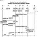
- Figure 7 shows the existence of 2 sessions already established for a given UE 34.
- the UE 34 has IP configuration for each session and can send and receive data over each session.
- the UE 34 is in Standby mobility state (shown as the CCNF 32 in Standby state)
- the corresponding session#1 state represented by the SMF1 42 in the CP
- session#2 state represented by the SMF2 44 in the CP
- the UPF1 46 and the UPF2 48 have a UE-related context (e.g. to enforce policies for the configured UE's IP addresses and association with the corresponding CPF like the SMF), but there is no connection/tunnel to any (R)AN node 30 to transmit packets.
- Solution 1.2 indication of session ID to UE during the Service request or corre sponding RRC establishment procedure
- Figure 8 shows an alternative solution where the paging procedure is enhanced to include the session ID parameter in the paging request message.
- Figure 8 shows that a paging procedure where the Paging message does not include a session ID, but instead the session ID for activation of a single PDU/PDN session is indicated to the UE 34 during the RRC connection establishment procedure. Only steps (5)-(9) are described in details below, as the rest of the steps are similar to Figure 7 .
- Step (5) The CCNF 32 sends a paging request towards the possible (R)AN nodes 30 where the UE 34 camps.
- the paging request message does not include a session ID parameter to indicate to the UE 34 which session should be activated.
- Step (6) The (R)AN node 30 performs paging over the radio interface. This message does not include the session ID as per step (5).
- Step (7) After the UE 34 receives a paging message, the UE 34 performs radio connection establishment with the (R)AN node 30 and sends a NAS Service Request message to the CCNF 32 over NG1.
- Step (8) The CCNF 32 determines (correlates) that the NAS Service Request message is as result to the Paging procedure.
- the CCNF 32 determines that only a session requested by the SMF2 44 in step (3) needs to be activated.
- the CCNF (e.g. MMF) 32 changes the UE mobility state from Standby state to Ready state.
- the CCNF 32 generates the corresponding UE context setup request message and sends it to the (R)AN node 30.
- the UE context setup request message contains, in addition to other UE parameters like QoS and security parameters, also a session ID parameter.
- this step (8) can be either executed session by session or one procedure activates all requested sessions at once (e.g. by including a list of all session IDs and corresponding parameters).
- Step (9) The (R)AN node 30 performs radio connection reconfiguration shown as RRC connection reconfiguration in the figure. During this procedure, the (R)AN node 30 indicates to the UE the session ID parameter for the session to be activated.
- the UE 34 can activate the corresponding service, application or existing PDN/APN/PDU/bearer context.
- the UE 34 does not activate all existing PDN/APN/PDU/bearer contexts, but only the indicated ones.
- the UE 34 updates its session/SM state(s) that corresponds to the session ID(s) received by step (9).
- the choice between the solution alternatives shown in Figure 7 or in Figure 8 can be done in the CCNF (e.g. MMF) 32 based on the capabilities of the (R)AN nodes 30 or based on the capabilities of the UE 34.
- the UE capabilities regarding supported paging feature(s) can be exchanged during the Attach procedure or other mobility procedure via NAS MM signaling.
- the (R)AN node capabilities can be exchanged during the interface setup between the (R)AN node 30 and the CCNF 32 (e.g. NG2 interface or S1-MME setup exchange).
- Solution 2 activation of session when other Active session(s) exist (e.g. UE is in MM Ready state)
- the scenario solved in solution 1 has the assumption that there are no other session in Active state (e.g. the UE 34 is in Standby mobility state)
- the assumption for solution 2 is that the UE 34 is in Ready mobility state during DL data is arriving for a session which is in Idle state.
- the UE 34 has an Active session context for Session#1 terminated at the UPF1 46.
- the unique problem is that the UE 34 already has existing PDU session (e.g. SM) contexts in Idle session state and the radio connection to be established shall be linked to this single PDU context out of multiple existing PDU session contexts. It is proposed that such a linkage between a new data radio connection/bearer and existing session context in the UE 34 is performed by using the session ID.
- PDU session e.g. SM
- Figure 9 shows a possible solution 2.1 for the activation of an additional session when another session is already in Active state.
- This solution 2.1 alternative is based on a new UE context modification request procedure.
- Figure 10 shows another alternative solution 2.2 where NAS SM signalling between the SMF2 44 and the UE 34 is used for the activation of the session 2 towards the UPF2 48.
- the SMF2 44 may trigger the session activation by itself, i.e. without trigger from the UPF2 48. This is possible in case there is a scheduled session activation in the SMF2 44.
- scheduling can be based on a timer or clock running in the SMF2 44 as part of the processing of the UE's SM context in the SMF2 44.
- the SMF2 44 based on such a clock for scheduling, can trigger the establishment of UP connection by performing step (3) towards the MMF 32, and perform a new step to insert UP-related information towards the UPF2 48 (basically step (11) above).
- solution 2.1 or solution 2.2 allows to activate an individual session (UP connection) while other UP connection exists.
- Solution 3 activation of session triggered by UL data (in the UE)
- solution 1 and solution 2 (with their variants) explain the activation of the UP connection triggered by DL data (in the UPF), this solution describes the activation of a single UP connection triggered by UL data (in the UE).
- Figure 11 shows that the UE 34 has two session contexts for session#1 and session#2. There are two different cases described. In case (A) the UE 34 is in Standby mobility (MM) state, and thus, all session states are in Idle state. In case (B) the UE 34 is in Ready mobility (MM) state and session#1 is in use, i.e. there are the radio connection and the NG3 connection established.
- MM Standby mobility
- MM Ready mobility
- Solution 4 deactivation of single session while other session(s) continue to be in Active state
- Solution 4.1 session deactivation initiated by the RAN node
- (R)AN node 30 triggers the deactivation of a session.
- the (R)AN node 30 manages radio related parameters, such as a UE inactivity timer, an active discontinuous reception (DRX) cycle, an idle DRX cycle, etc.
- radio related parameters such as a UE inactivity timer, an active discontinuous reception (DRX) cycle, an idle DRX cycle, etc.
- This solution proposes that such radio parameters are maintained per session.
- the (R)AN node 30 maintains a so called “session inactivity timer” per activated session.
- This "session inactivity timer” is different from the UE inactivity timer, as the “session inactivity timer” applies to a single session (a radio connection like a data radio bearer (DRB) in LTE).
- DRB data radio bearer
- Figure 12 describes a case where two sessions are Active and one of them becomes Idle due to no user plane activity within a predefined UE inactivity period determined by the (R)AN node 30.
- the thick arrows show the data flow in UL and DL between the UE 34 and, the UPF1 46 and the UPF2 48 correspondingly.
- FIG 13 describes an alternative solution where the session deactivation procedure is initiated by the UPF of the corresponding session.
- This solution proposes that each UPF manages an inactivity timer, which can be called a "session inactivity timer".
- This timer can be configured by the SMF when a session is activated, e.g. step (12) in Figure 7 or in Figure 8 can contain a "session inactivity timer" parameter.
- the UPF measures the time for which there are no DL or UL data exchanged. When the measured time for data inactivity reaches the value of the parameter "session inactivity timer", the UPF triggers a UP connection release procedure.
- the UE 34 is in MM Ready state and session#1 and session#2 are activated. This is shown by the thick arrows corresponding to 2 radio connections and 2 NG3 connections between the (R)AN node 30 and, the UPF1 46 and the UPF2 48 correspondingly.
- Another alternative to solution 4.2 would be to use a NAS SM Session deactivation procedure between the SMF1 42 and the UE 34.
- This procedure can be used by the SMF1 42 to inform the UE 34 about the SM context deactivation, which results in changing the session SM state in the UE 34 from Active to Idle.
- Such a NAS SM procedure can be initiated by the SMF1 42 in parallel to steps (3), (4) and (5) in Figure 13 .
- Solution 4.3 session deactivation initiated by the UE
- an Application associated with session A indicates to the NAS SM instance in the UE 34 that such an application does not need any more UP connections, or the NAS SM instance is aware by any means that the active UP connection is not used, the UE's NAS SM instance for session A can initiate session deactivation procedure towards the NG CN. The following steps can be performed:
- the examples above describe solutions for the activation or deactivation of a single session. However, it is also possible to activate/deactivate several sessions simultaneously by including several Session IDs in the corresponding messages.
- the activation of several sessions simultaneously can be beneficial in case of multiple PDU sessions per data network, where it is assumed that the same SMF controls the multiple PDU sessions.
- the SMF decides whether to activate a single PDU session (e.g. to which DL data arrives) or to activate some or even all PDU session controlled by this SMF (which probably means some or all PDU sessions toward a particular network slice or data network).
- the signalling to/from the (R)AN node 30 over NG2 interface can be terminated at a common front-end NG2 termination functionality in the CCNF 32.
- the common front-end NG2 functionality can route/forward the content of the NG2 message to the MMF 32 and/or the SMF2 44.
- the (R)AN node 30 sends 2 different NG2 messages, a separate message to the MMF 32 and a separate message to the SMF2 44.
- the message to the MMF 32 may request an MM-specific action or can confirm the successful establishment/release of a data radio connection.
- the message to the SMF2 44 can mainly contain (R)AN node UP NG3-related information (e.g. tunnelling information like the IP address of UPF2 48 and/or the GTP TEID).
- the UE 34 is modified to be able to handle the signaling to/from the (R)AN and CN functional entities (e.g. (R)AN node, MMF, SMF).
- the UE 34 is able to receive, process and transmit the corresponding information to the (R)AN and CN functional entities.
- the UE 34 can be described schematically via the block diagram as in Figure 14 .
- FIG 14 is a block diagram illustrating the main components of the user equipment (UE) 34 shown in e.g. Figure 1 (where it is denoted ⁇ NG UE').
- the UE 34 has a transceiver circuit 50 that is operable to transmit signals to and to receive signals from a radio access network node 30 via one or more antenna 52.
- Such radio access network node 30 may comprise a base station and/or any other suitable access point / transmission point.
- the UE 34 has a controller 54 to control the operation of the UE 34.
- the controller 54 is associated with a memory 56 and is coupled to the transceiver circuit 50.
- the UE 34 may have all the usual functionality of a conventional mobile device / mobile telephone (such as a user interface) and this may be provided by any one or any combination of hardware, software and firmware, as appropriate.
- Software may be pre-installed in the memory 56 and/or may be downloaded via the telecommunication network or from a removable data storage device (RMD), for example.
- RMD removable data storage device
- the controller 54 controls overall operation of the UE 34 by, in this example, program instructions or software instructions stored within the memory 56. As shown, these software instructions include, among other things, an operating system 58, a communication control module 60, and a transceiver control module 62 (shown as forming part of the communication control module 60).
- the communication control module 60 controls the communication between the UE 34 and the base station / access node of the (R)AN.
- the communications control module 60 also controls the separate flows of control data (Control Plane) and user data (User Plane, both uplink and downlink) that are to be transmitted to the base station / access node and other nodes (via the base station / access node) such as the Mobility Management Function (MMF) and the Session Management Function (SMF).
- MMF Mobility Management Function
- SMF Session Management Function
- the Mobility Management Function (MMF) or Session Management Function (SMF) is modified/extended to be able to behave according to the proposed solution(s).
- MMF Mobility Management Function
- SMF Session Management Function
- FIG 15 is a block diagram illustrating the main components of the Mobility Management Function (MMF) / Session Management Function (SMF) node shown in e.g. Figure 1 .
- MMF Mobility Management Function
- SMF Session Management Function
- the MMF/SMF has a transceiver circuit 64 and a network interface 66 for transmitting signals to and for receiving signals from other network nodes (including the UE 34).
- the MMF/SMF has a controller 68 to control the operation of the MMF/ SMF node.
- the controller 68 is associated with a memory 70.
- Software may be pre-installed in the memory 70 and/or may be downloaded via the communication network or from a removable data storage device (RMD), for example.
- the controller 68 is configured to control the overall operation of the MMF/SMF by, in this example, program instructions or software instructions stored within the memory 70.
- these software instructions include, among other things, an operating system 72, a communication control module 74, and a transceiver control module 76 (shown as forming part of the communication control module 74).
- the communication control module 74 controls the communication between the MMF/SMF and other network entities that are connected to the MMF/SMF (e.g. the base station / access node, and the UE 34 when connected to a base station / access node).
- the above described example embodiments include, although they are not limited to, one or more of the following functionalities.
- the UE and the MMF/SMF node are described for ease of understanding as having a number of discrete modules (such as the communication control modules). Whilst these modules may be provided in this way for certain applications, for example where an existing system has been modified to implement the invention, in other applications, for example in systems designed with the inventive features in mind from the outset, these modules may be built into the overall operating system or code and so these modules may not be discernible as discrete entities. These modules may also be implemented in software, hardware, firmware or a mix of these.
- Each controller may comprise any suitable form of processing circuitry including (but not limited to), for example: one or more hardware implemented computer processors; microprocessors; central processing units (CPUs); arithmetic logic units (ALUs); input/output (IO) circuits; internal memories / caches (program and/or data); processing registers; communication buses (e.g. control, data and/or address buses); direct memory access (DMA) functions; hardware or software implemented counters, pointers and/or timers; and/or the like.
- processing circuitry including (but not limited to), for example: one or more hardware implemented computer processors; microprocessors; central processing units (CPUs); arithmetic logic units (ALUs); input/output (IO) circuits; internal memories / caches (program and/or data); processing registers; communication buses (e.g. control, data and/or address buses); direct memory access (DMA) functions; hardware or software implemented counters, pointers and/or timers; and/or the like.
- the software modules may be provided in compiled or un-compiled form and may be supplied to the UE and the MMF/SMF node as a signal over a computer network, or on a recording medium. Further, the functionality performed by part or all of this software may be performed using one or more dedicated hardware circuits. However, the use of software modules is preferred as it facilitates the updating of the UE and the MMF/SMF node in order to update their functionalities.
Landscapes
- Engineering & Computer Science (AREA)
- Signal Processing (AREA)
- Computer Networks & Wireless Communication (AREA)
- Computer Security & Cryptography (AREA)
- Databases & Information Systems (AREA)
- Mobile Radio Communication Systems (AREA)
- Communication Control (AREA)
- Computer And Data Communications (AREA)
Applications Claiming Priority (4)
| Application Number | Priority Date | Filing Date | Title |
|---|---|---|---|
| EP16185042 | 2016-08-19 | ||
| PCT/JP2017/029618 WO2018034337A1 (en) | 2016-08-19 | 2017-08-18 | Method for user plane connection activation or deactivation per session |
| EP21202925.0A EP3972378B1 (de) | 2016-08-19 | 2017-08-18 | Aktivierung oder deaktivierung von pdu sessions |
| EP17764913.4A EP3501232B1 (de) | 2016-08-19 | 2017-08-18 | Aktivierung oder deaktivierung von pdu sessions |
Related Parent Applications (3)
| Application Number | Title | Priority Date | Filing Date |
|---|---|---|---|
| EP17764913.4A Division EP3501232B1 (de) | 2016-08-19 | 2017-08-18 | Aktivierung oder deaktivierung von pdu sessions |
| EP21202925.0A Division EP3972378B1 (de) | 2016-08-19 | 2017-08-18 | Aktivierung oder deaktivierung von pdu sessions |
| EP21202925.0A Division-Into EP3972378B1 (de) | 2016-08-19 | 2017-08-18 | Aktivierung oder deaktivierung von pdu sessions |
Publications (2)
| Publication Number | Publication Date |
|---|---|
| EP4376540A2 true EP4376540A2 (de) | 2024-05-29 |
| EP4376540A3 EP4376540A3 (de) | 2024-08-07 |
Family
ID=59846614
Family Applications (3)
| Application Number | Title | Priority Date | Filing Date |
|---|---|---|---|
| EP23213830.5A Pending EP4376540A3 (de) | 2016-08-19 | 2017-08-18 | Verfahren zur aktivierung oder deaktivierung einer verbindung auf benutzerebene pro sitzung |
| EP21202925.0A Active EP3972378B1 (de) | 2016-08-19 | 2017-08-18 | Aktivierung oder deaktivierung von pdu sessions |
| EP17764913.4A Active EP3501232B1 (de) | 2016-08-19 | 2017-08-18 | Aktivierung oder deaktivierung von pdu sessions |
Family Applications After (2)
| Application Number | Title | Priority Date | Filing Date |
|---|---|---|---|
| EP21202925.0A Active EP3972378B1 (de) | 2016-08-19 | 2017-08-18 | Aktivierung oder deaktivierung von pdu sessions |
| EP17764913.4A Active EP3501232B1 (de) | 2016-08-19 | 2017-08-18 | Aktivierung oder deaktivierung von pdu sessions |
Country Status (8)
| Country | Link |
|---|---|
| US (4) | US11026292B2 (de) |
| EP (3) | EP4376540A3 (de) |
| JP (4) | JP6961899B2 (de) |
| CN (4) | CN116347660A (de) |
| ES (2) | ES2901012T3 (de) |
| MX (1) | MX2019001997A (de) |
| RU (4) | RU2734642C2 (de) |
| WO (1) | WO2018034337A1 (de) |
Families Citing this family (76)
| Publication number | Priority date | Publication date | Assignee | Title |
|---|---|---|---|---|
| JP6978421B2 (ja) * | 2016-09-30 | 2021-12-08 | 株式会社Nttドコモ | 移動体通信システム |
| US11419177B2 (en) | 2016-10-11 | 2022-08-16 | Nec Corporation | Method, session management function node, user plane function node, and user equipment for session management parameters maintenance and computer readable recording medium therein |
| US11528648B2 (en) * | 2016-11-15 | 2022-12-13 | Nokia Technologies Oy | Hybrid release for processing user equipment transaction |
| CN110248382B (zh) | 2017-01-05 | 2020-09-08 | 华为技术有限公司 | 信息传输的方法和装置 |
| CN114125964B (zh) * | 2017-01-06 | 2024-04-05 | 北京三星通信技术研究有限公司 | 用于无线网络系统之间的数据传送控制的方法及设备 |
| EP3569004B1 (de) * | 2017-01-10 | 2022-04-06 | Nokia Technologies Oy | Kurznachrichtendienst über non-access-stratum mit home-routing-modell |
| CN108574969B (zh) * | 2017-03-08 | 2021-04-09 | 华为技术有限公司 | 多接入场景中的连接处理方法和装置 |
| CN108966691B (zh) * | 2017-03-20 | 2022-01-11 | Lg 电子株式会社 | 管理会话和smf节点的方法 |
| ES2959853T3 (es) * | 2017-05-09 | 2024-02-28 | Huawei Tech Co Ltd | Método de gestión de sesiones y elemento de red de función de gestión de sesiones |
| EP3419378A1 (de) * | 2017-06-19 | 2018-12-26 | Industrial Technology Research Institute | Verfahren zur standortverfolgung und zugehörige vorrichtung mit verwendung davon |
| CN109429361B (zh) * | 2017-07-18 | 2021-01-01 | 华为技术有限公司 | 会话处理方法及装置 |
| CN109548092B (zh) * | 2017-07-28 | 2021-04-09 | 华为技术有限公司 | 一种激活session的方法、设备及系统 |
| US11871291B2 (en) * | 2017-08-04 | 2024-01-09 | Apple Inc. | Data forwarding tunnel establishment between two user plane functions in fifth generation |
| KR102329925B1 (ko) * | 2017-08-14 | 2021-11-23 | 삼성전자 주식회사 | 4g/5g 동시 등록된 이동 통신 단말을 위한 네트워크 이동시 데이터 동기화 제공 방안 |
| CN112202842A (zh) * | 2017-08-29 | 2021-01-08 | 华为技术有限公司 | 数据传输方法、设备及系统 |
| CN109842955B (zh) * | 2017-09-23 | 2023-11-21 | 华为技术有限公司 | 通信方法及装置 |
| US11219088B2 (en) * | 2017-09-28 | 2022-01-04 | Lg Electronics Inc. | Method and apparatus for configuring release cause |
| CA3020118A1 (en) | 2017-10-09 | 2019-04-09 | Comcast Cable Communications, Llc | Ethernet type packet data unit session communications |
| US10855814B2 (en) | 2017-10-20 | 2020-12-01 | Comcast Cable Communications, Llc | Non-access stratum capability information |
| KR102106778B1 (ko) * | 2017-10-31 | 2020-05-28 | 에스케이텔레콤 주식회사 | 데이터 송수신장치 및 데이터 송수신장치의 동작 방법 |
| US10785637B2 (en) * | 2017-11-17 | 2020-09-22 | Ofinno, Llc | SMF selection for isolated network slice |
| US10959142B2 (en) * | 2017-11-20 | 2021-03-23 | Ofinno, Llc | Extended buffering management |
| CN113473646B (zh) * | 2017-11-21 | 2022-04-12 | 华为技术有限公司 | 一种通信方法及装置 |
| WO2019119447A1 (en) * | 2017-12-22 | 2019-06-27 | Qualcomm Incorporated | Expedited release of a user equipment |
| GB2569989B (en) * | 2018-01-08 | 2020-01-15 | Tcl Communication Ltd | Paging in cellular communication systems |
| US12058763B2 (en) * | 2018-02-18 | 2024-08-06 | Lg Electronics Inc. | Signal transmission and reception method by SMF in wireless communication system and device therefor |
| WO2019165629A1 (zh) * | 2018-03-01 | 2019-09-06 | 华为技术有限公司 | 会话管理方法及装置、通信系统 |
| EP4210424A1 (de) * | 2018-03-23 | 2023-07-12 | Samsung Electronics Co., Ltd. | Verfahren, endgerät und netzwerkeinheit zur handhabung eines dienstanfrageverfahrens in einem kommunikationsnetzwerk |
| US10548107B2 (en) * | 2018-03-29 | 2020-01-28 | Apple Inc. | Delaying cellular re-registration during critical conditions |
| CN110366215B (zh) * | 2018-04-09 | 2020-12-15 | 华为技术有限公司 | 会话管理的方法、终端和核心网设备 |
| WO2019219619A1 (en) * | 2018-05-14 | 2019-11-21 | Telefonaktiebolaget Lm Ericsson (Publ) | Methods, system and nodes of optimized inactivity timer usage in 5gs |
| CN110519809B (zh) * | 2018-05-21 | 2020-12-15 | 华为技术有限公司 | 管理pdu会话的方法、网元、设备、装置、系统和存储介质 |
| CN110519840B (zh) * | 2018-05-21 | 2021-01-15 | 中国移动通信有限公司研究院 | 会话处理方法及装置、网元及存储介质 |
| CN110519746B (zh) | 2018-05-21 | 2021-07-16 | 华为技术有限公司 | 一种用于终止接入和移动性管理策略关联的方法和装置 |
| CN110650167B (zh) * | 2018-06-26 | 2021-02-23 | 华为技术有限公司 | 通信方法和装置 |
| CN110740149B (zh) | 2018-07-19 | 2021-04-09 | 华为技术有限公司 | 通信方法和装置 |
| US11039369B2 (en) | 2018-08-10 | 2021-06-15 | Mediatek Inc. | Handling 5G QoS rules on QoS operation errors |
| CN110831249B (zh) * | 2018-08-13 | 2021-10-01 | 华为技术有限公司 | 通信方法和装置 |
| US10855851B2 (en) * | 2018-09-13 | 2020-12-01 | Ofinno, Llc | Charging control with SMF |
| US11206710B2 (en) * | 2018-09-25 | 2021-12-21 | Ofinno, Llc | Network initiated release assistance indication |
| US20200113009A1 (en) * | 2018-10-06 | 2020-04-09 | Mediatek Inc. | Handling Of Invalid Mandatory Information In Mobile Communications |
| KR102767573B1 (ko) | 2018-10-31 | 2025-02-12 | 광동 오포 모바일 텔레커뮤니케이션즈 코포레이션 리미티드 | 프로토콜 데이터 유닛 세션 상태 지시 방법, 단말 기기 및 저장 매체 |
| CN111200878B (zh) * | 2018-11-19 | 2022-04-22 | 华为技术有限公司 | 信息传输方法及其装置 |
| US11483886B2 (en) * | 2018-12-21 | 2022-10-25 | T-Mobile Usa, Inc. | Staggered IMS bearer activation and radio bearer activation in 5G non-standalone networks |
| CN111436115B (zh) * | 2019-01-15 | 2021-10-15 | 大唐移动通信设备有限公司 | 一种pdu会话激活方法、寻呼方法及其装置 |
| EP3928490A1 (de) | 2019-02-18 | 2021-12-29 | Nokia Technologies Oy | Verfahren und vorrichtung zur erzielung von nas-signalisierung über einen anderen zugriff |
| CN113632439B (zh) * | 2019-03-27 | 2024-03-15 | 瑞典爱立信有限公司 | 支持虚拟以太网网桥管理的蜂窝通信系统 |
| CN112188608B (zh) * | 2019-07-04 | 2022-01-14 | 华为技术有限公司 | 一种同步pdu会话状态的方法、装置、系统及芯片 |
| CN113412665B (zh) * | 2019-07-12 | 2023-09-22 | Oppo广东移动通信有限公司 | 一种会话设置方法、网络设备、用户设备 |
| WO2021063981A1 (en) * | 2019-10-03 | 2021-04-08 | Telefonaktiebolaget Lm Ericsson (Publ) | Network slice bit rate enforcement |
| US11108636B2 (en) | 2019-10-23 | 2021-08-31 | Cisco Technology, Inc. | Integrity verification for managing network configurations |
| EP4138431A1 (de) * | 2019-11-02 | 2023-02-22 | Apple Inc. | Verfahren und vorrichtung zur unterstützung des zugriffs auf dienste für mehrere teilnehmeridentitätsmodule |
| CN115426656B (zh) * | 2019-11-02 | 2026-03-20 | 苹果公司 | 支持访问用于多个用户身份模块的服务的方法和装置 |
| EP4079096B1 (de) * | 2019-12-19 | 2024-08-07 | Telefonaktiebolaget LM Ericsson (publ) | Verfahren und vorrichtung zur signalisierung von sitzungsabschlüssen in einem kommunikationsnetzwerk |
| CN113133063B (zh) * | 2019-12-30 | 2024-04-26 | 中兴通讯股份有限公司 | 一种会话释放方法、电子设备及存储介质 |
| US12279125B2 (en) * | 2020-02-13 | 2025-04-15 | Telefonaktiebolaget Lm Ericsson (Publ) | Registered UE count in slice service area |
| US20230055913A1 (en) * | 2020-03-12 | 2023-02-23 | Telefonaktiebolaget Lm Ericsson (Publ) | Network Service Management |
| US11425602B2 (en) * | 2020-04-21 | 2022-08-23 | Google Llc | Load balancing and service selection in mobile networks |
| EP4186324A1 (de) * | 2020-07-23 | 2023-05-31 | Lenovo (Singapore) Pte. Ltd. | Freigabe von ressourcen auf benutzerebene einer datenverbindung |
| GB2598100B (en) * | 2020-08-13 | 2024-11-06 | Samsung Electronics Co Ltd | Setting timer value in network |
| WO2022081832A2 (en) * | 2020-10-14 | 2022-04-21 | Weihua Qiao | Communication network |
| GB2600920B (en) * | 2020-11-04 | 2022-12-28 | Metaswitch Networks Ltd | Network slicing |
| CN114501490B (zh) * | 2020-11-13 | 2024-04-02 | 维沃移动通信有限公司 | 业务转移方法、终端及网络侧设备 |
| CN114554487A (zh) * | 2020-11-24 | 2022-05-27 | 华为技术有限公司 | 通信系统、通信的方法及通信装置 |
| US11602003B1 (en) | 2021-03-17 | 2023-03-07 | T-Mobile Innovations Llc | Wireless communication network to serve a user equipment (UE) over a user plane function group (UPFG) |
| US20240276384A1 (en) * | 2021-06-15 | 2024-08-15 | Telefonaktiebolaget Lm Ericsson (Publ) | Controlling device usage with respect to slices |
| CN115734398B (zh) * | 2021-08-25 | 2025-09-05 | 华为技术有限公司 | 一种通信方法及装置 |
| JP7773352B2 (ja) | 2021-11-30 | 2025-11-19 | 大王製紙株式会社 | パンツ式おむつ |
| KR20230105947A (ko) * | 2022-01-05 | 2023-07-12 | 삼성전자주식회사 | 무선 통신 시스템에서 upf 기능 분리에 따른 네트워크에서 신호 전송을 위한 장치 및 방법 |
| US20230371017A1 (en) * | 2022-05-12 | 2023-11-16 | Qualcomm Incorporated | Communications carried via a user equipment |
| US12323304B2 (en) * | 2022-05-16 | 2025-06-03 | Nokia Solutions And Networks Oy | Method to update 5G VN group topology update to AF for efficient network management |
| US12452103B2 (en) | 2022-07-26 | 2025-10-21 | Nokia Solutions And Networks Oy | Combined PFCP session model for network access by residential gateways |
| US12301383B2 (en) * | 2022-07-26 | 2025-05-13 | Nokia Solutions And Networks Oy | Separate PFCP session model for network access by residential gateways |
| CN117956412A (zh) * | 2022-10-20 | 2024-04-30 | 大唐移动通信设备有限公司 | 一种信息传输方法、装置及设备 |
| US12081405B1 (en) * | 2023-04-24 | 2024-09-03 | Verizon Patent And Licensing Inc. | Systems and methods for enhanced session management policy interface in a wireless network |
| US20250176059A1 (en) * | 2023-11-29 | 2025-05-29 | Cisco Technology, Inc. | Session establishment in a wireless network in view of interface failure |
Family Cites Families (48)
| Publication number | Priority date | Publication date | Assignee | Title |
|---|---|---|---|---|
| US6654360B1 (en) * | 2000-01-10 | 2003-11-25 | Qualcomm Incorporated | Method and system for providing dormant mode wireless packet data services |
| JP4213183B2 (ja) * | 2004-07-30 | 2009-01-21 | シャープ株式会社 | 通信ネットワークの制御システム |
| US20060045128A1 (en) | 2004-09-01 | 2006-03-02 | Lila Madour | Per flow quality of service (QoS) enforcement for downlink data traffic |
| JP2007180889A (ja) | 2005-12-28 | 2007-07-12 | Nec Corp | 無線LANシステム、制御装置、無線基地局及びそれらに用いるQoS制御方法 |
| KR101233181B1 (ko) | 2006-10-30 | 2013-02-15 | 엘지전자 주식회사 | 무선 통신 시스템에서의 랜덤 억세스 방법 |
| US8144650B2 (en) * | 2006-12-22 | 2012-03-27 | Telefonaktiebolaget L M Ericsson (Publ) | Method and arrangement relating to communications network services request activation |
| EP2285174B1 (de) | 2007-01-15 | 2013-01-02 | Telefonaktiebolaget L M Ericsson (Publ) | Verfahren und Anordnungen für leitungsvermittelte Dienste in einem Kommunikationsnetzwerk |
| US8139530B2 (en) * | 2007-03-22 | 2012-03-20 | Telefonaktiebolaget L M Ericsson (Publ) | Mobility management (MM) and session management (SM) for SAE/LTE |
| US8194540B2 (en) | 2007-08-08 | 2012-06-05 | Samsung Electronics Co., Ltd. | Apparatus and method for managing quality of service of service flow in wireless communication system |
| ATE553628T1 (de) * | 2007-11-13 | 2012-04-15 | Research In Motion Ltd | Verfahren und vorrichtung für status- /modusübergänge |
| ATE542389T1 (de) | 2008-04-24 | 2012-02-15 | Ericsson Telefon Ab L M | Verfahren, vorrichtung und computerprogramm zur unterstützung einer sitzungskennung im fall eines transfers zwischen verschiedenen funkzugangsnetzen |
| US9124608B2 (en) | 2008-06-19 | 2015-09-01 | Qualcomm Incorporated | Conveying session continuity information in a multi-component communication session |
| US8761813B2 (en) | 2008-11-26 | 2014-06-24 | Alcatel Lucent | Fast signaling services for E-UTRAN based wireless systems |
| US8711772B2 (en) * | 2009-05-22 | 2014-04-29 | Qualcomm Incorporated | Paging of a user equipment (UE) within a wireless communications system |
| US20100322189A1 (en) * | 2009-06-19 | 2010-12-23 | Telefonaktiebolaget L M Ericsson (Publ) | Supporting optimized handover of a user equipment between dissimilar networks |
| CN101730142B (zh) * | 2009-06-30 | 2012-09-05 | 中兴通讯股份有限公司 | 多分组数据网络连接的建立方法以及装置 |
| CN102056112B (zh) * | 2009-11-05 | 2015-03-25 | 华为技术有限公司 | 一种传输数据的方法、设备和系统 |
| RU2696338C2 (ru) | 2009-11-10 | 2019-08-01 | Телефонактиеболагет Л М Эрикссон (Пабл) | Оптимизация задержки при передаче обслуживания |
| CN102088771B (zh) | 2010-03-12 | 2013-10-16 | 电信科学技术研究院 | 根据ue状态进行数据面通路选择的方法、系统及装置 |
| CN102378120B (zh) | 2010-08-24 | 2015-10-21 | 中兴通讯股份有限公司 | 一种寻呼方法及系统 |
| CA2812954C (en) * | 2010-09-28 | 2018-05-01 | Research In Motion Limited | Residential/enterprise network connection management and handover scenarios |
| US8649286B2 (en) * | 2011-01-18 | 2014-02-11 | Apple Inc. | Quality of service (QoS)-related fabric control |
| EP2683183A1 (de) * | 2011-04-05 | 2014-01-08 | Panasonic Corporation | Verbesserte Kurznachrichtenübertragung |
| GB2489545B (en) * | 2011-11-29 | 2013-05-29 | Renesas Mobile Corp | Method, apparatus and computer program for establishing an emergency service |
| CN103428636B (zh) * | 2012-05-17 | 2016-04-06 | 大唐移动通信设备有限公司 | 一种组呼建立方法 |
| US9544927B2 (en) * | 2012-07-02 | 2017-01-10 | Alcatel Lucent | System, method and computer readable medium for bearer activation in a core network for wireless devices |
| KR20140004582A (ko) * | 2012-07-02 | 2014-01-13 | 주식회사 케이티 | 모바일 데이터 애플리케이션에 의한 소량 데이터 분류 처리 방법 및 장치 |
| WO2014067144A1 (zh) | 2012-11-02 | 2014-05-08 | 华为技术有限公司 | 群组寻呼方法、基站及用户设备 |
| JP2014096662A (ja) | 2012-11-08 | 2014-05-22 | Ntt Docomo Inc | 無線通信システムおよび通信制御方法 |
| US10164693B2 (en) * | 2013-05-09 | 2018-12-25 | Intel IP Corporation | Reduction of buffer overflow |
| US9445343B2 (en) * | 2013-07-09 | 2016-09-13 | Alcatel Lucent | Systems for switching modes in wireless sessions |
| US9578476B2 (en) * | 2013-07-09 | 2017-02-21 | Telefonaktiebolaget Lm Ericsson (Publ) | Method and apparatus in a telecommunication system |
| CN103442425A (zh) | 2013-08-21 | 2013-12-11 | 大唐移动通信设备有限公司 | 一种指示寻呼、寻呼的方法及设备 |
| US9860834B2 (en) * | 2013-09-13 | 2018-01-02 | Lg Electronics Inc. | Method for reselecting network node in charge of control plane |
| WO2015139773A1 (en) * | 2014-03-21 | 2015-09-24 | Nokia Solutions And Networks Oy | Resource release for proximity-based communications |
| EP3132622B1 (de) * | 2014-04-15 | 2019-09-25 | Nokia Solutions and Networks Oy | Zusammenarbeit mit trägerbasiertem system |
| EP3145259B1 (de) | 2014-05-30 | 2022-08-24 | Huawei Technologies Co., Ltd. | Trägeraufbauvorrichtung und verfahren |
| US9723642B2 (en) * | 2014-08-07 | 2017-08-01 | At&T Intellectual Property I, L.P. | Method and device for managing communication sessions using tunnels |
| US10075888B2 (en) * | 2014-09-25 | 2018-09-11 | Qualcomm Incorporated | Service-specific air-interface selection |
| JP2016076808A (ja) * | 2014-10-06 | 2016-05-12 | 富士通株式会社 | 中継装置、及びセッション開放制御方法 |
| BR112017004554A2 (pt) * | 2014-10-07 | 2017-12-05 | Intel Ip Corp | retomada aprimorada de conexões de pdn para dispositivos que recuperam conectividade de wlan |
| US9949176B2 (en) * | 2014-11-10 | 2018-04-17 | Nxp Usa, Inc. | Wireless communication apparatus and method |
| US20180270741A1 (en) * | 2014-11-11 | 2018-09-20 | Sharp Kabushiki Kaisha | Terminal device, base station device, mme, and communication control method |
| US20190037636A1 (en) | 2016-02-17 | 2019-01-31 | Lg Electronics Inc. | Method for transmitting/receiving location registration-related message in wireless communication system and apparatus for same |
| US10362511B2 (en) * | 2016-05-17 | 2019-07-23 | Lg Electronics Inc. | Method and apparatus for determining PDU session identity in wireless communication system |
| CN113613293B (zh) | 2016-07-01 | 2024-04-16 | 交互数字专利控股公司 | 用于在wtru中所使用的方法及wtru |
| JP6925411B2 (ja) | 2016-08-16 | 2021-08-25 | アイディーエーシー ホールディングス インコーポレイテッド | ネットワークスライス再選択 |
| US10779346B2 (en) | 2017-03-27 | 2020-09-15 | Qualcomm Incorporated | Local area data network connectivity |
-
2017
- 2017-08-18 CN CN202310332703.3A patent/CN116347660A/zh active Pending
- 2017-08-18 RU RU2020111437A patent/RU2734642C2/ru active
- 2017-08-18 EP EP23213830.5A patent/EP4376540A3/de active Pending
- 2017-08-18 ES ES17764913T patent/ES2901012T3/es active Active
- 2017-08-18 MX MX2019001997A patent/MX2019001997A/es unknown
- 2017-08-18 JP JP2019508979A patent/JP6961899B2/ja active Active
- 2017-08-18 US US16/321,304 patent/US11026292B2/en active Active
- 2017-08-18 RU RU2019107584A patent/RU2720449C1/ru active
- 2017-08-18 ES ES21202925T patent/ES2970700T3/es active Active
- 2017-08-18 EP EP21202925.0A patent/EP3972378B1/de active Active
- 2017-08-18 WO PCT/JP2017/029618 patent/WO2018034337A1/en not_active Ceased
- 2017-08-18 EP EP17764913.4A patent/EP3501232B1/de active Active
- 2017-08-18 CN CN202310340678.3A patent/CN116347662A/zh active Pending
- 2017-08-18 CN CN202310340654.8A patent/CN116347661B/zh active Active
- 2017-08-18 RU RU2020111432A patent/RU2734894C2/ru active
- 2017-08-18 CN CN201780050571.8A patent/CN109644514B/zh active Active
-
2020
- 2020-10-08 RU RU2020133148A patent/RU2764259C1/ru active
-
2021
- 2021-03-18 US US17/205,848 patent/US11924921B2/en active Active
- 2021-09-22 JP JP2021154016A patent/JP2021193831A/ja active Pending
-
2022
- 2022-11-08 JP JP2022178978A patent/JP7444222B2/ja active Active
-
2023
- 2023-01-09 US US18/094,461 patent/US20230164881A1/en active Pending
- 2023-03-27 JP JP2023049268A patent/JP7700813B2/ja active Active
-
2025
- 2025-05-27 US US19/218,725 patent/US20250287464A1/en active Pending
Non-Patent Citations (2)
| Title |
|---|
| "General Packet Radio Service (GPRS) enhancements for Evolved Universal Terrestrial Radio Access Network (E-UTRAN) access", 3GPP TS 23.401, June 2016 (2016-06-01) |
| "Study on Architecture for Next Generation System", 3GPP TR 23.799 |
Also Published As
Similar Documents
| Publication | Publication Date | Title |
|---|---|---|
| US20250287464A1 (en) | Method for user plane connection activation or deactivation per session | |
| US11903083B2 (en) | Method, session management function node, user plane function node, and user equipment for session management parameters maintenance and computer readable recording medium therein | |
| EP3884719B1 (de) | Funkruf einer drahtlosen vorrichtung durch ein drahtloses netzwerk | |
| WO2021076927A1 (en) | Signaling delivery in a wireless network |
Legal Events
| Date | Code | Title | Description |
|---|---|---|---|
| PUAI | Public reference made under article 153(3) epc to a published international application that has entered the european phase |
Free format text: ORIGINAL CODE: 0009012 |
|
| STAA | Information on the status of an ep patent application or granted ep patent |
Free format text: STATUS: REQUEST FOR EXAMINATION WAS MADE |
|
| 17P | Request for examination filed |
Effective date: 20231201 |
|
| AC | Divisional application: reference to earlier application |
Ref document number: 3501232 Country of ref document: EP Kind code of ref document: P Ref document number: 3972378 Country of ref document: EP Kind code of ref document: P |
|
| AK | Designated contracting states |
Kind code of ref document: A2 Designated state(s): AL AT BE BG CH CY CZ DE DK EE ES FI FR GB GR HR HU IE IS IT LI LT LU LV MC MK MT NL NO PL PT RO RS SE SI SK SM TR |
|
| REG | Reference to a national code |
Ref country code: DE Ref legal event code: R079 Free format text: PREVIOUS MAIN CLASS: H04W0076120000 Ipc: H04W0076000000 |
|
| PUAL | Search report despatched |
Free format text: ORIGINAL CODE: 0009013 |
|
| AK | Designated contracting states |
Kind code of ref document: A3 Designated state(s): AL AT BE BG CH CY CZ DE DK EE ES FI FR GB GR HR HU IE IS IT LI LT LU LV MC MK MT NL NO PL PT RO RS SE SI SK SM TR |
|
| RIC1 | Information provided on ipc code assigned before grant |
Ipc: H04W 92/24 20090101ALN20240703BHEP Ipc: H04W 88/14 20090101ALN20240703BHEP Ipc: H04W 76/12 20180101ALI20240703BHEP Ipc: H04W 76/00 20180101AFI20240703BHEP |
|
| STAA | Information on the status of an ep patent application or granted ep patent |
Free format text: STATUS: EXAMINATION IS IN PROGRESS |
|
| 17Q | First examination report despatched |
Effective date: 20250417 |