EP4375621A1 - Vorrichtung und verfahren zur positions-, längen- oder winkelbestimmung - Google Patents
Vorrichtung und verfahren zur positions-, längen- oder winkelbestimmung Download PDFInfo
- Publication number
- EP4375621A1 EP4375621A1 EP22209571.3A EP22209571A EP4375621A1 EP 4375621 A1 EP4375621 A1 EP 4375621A1 EP 22209571 A EP22209571 A EP 22209571A EP 4375621 A1 EP4375621 A1 EP 4375621A1
- Authority
- EP
- European Patent Office
- Prior art keywords
- receiving
- area
- elements
- receiving elements
- reception
- Prior art date
- Legal status (The legal status is an assumption and is not a legal conclusion. Google has not performed a legal analysis and makes no representation as to the accuracy of the status listed.)
- Granted
Links
Images



Classifications
-
- G—PHYSICS
- G01—MEASURING; TESTING
- G01D—MEASURING NOT SPECIALLY ADAPTED FOR A SPECIFIC VARIABLE; ARRANGEMENTS FOR MEASURING TWO OR MORE VARIABLES NOT COVERED IN A SINGLE OTHER SUBCLASS; TARIFF METERING APPARATUS; MEASURING OR TESTING NOT OTHERWISE PROVIDED FOR
- G01D5/00—Mechanical means for transferring the output of a sensing member; Means for converting the output of a sensing member to another variable where the form or nature of the sensing member does not constrain the means for converting; Transducers not specially adapted for a specific variable
- G01D5/12—Mechanical means for transferring the output of a sensing member; Means for converting the output of a sensing member to another variable where the form or nature of the sensing member does not constrain the means for converting; Transducers not specially adapted for a specific variable using electric or magnetic means
-
- G—PHYSICS
- G01—MEASURING; TESTING
- G01D—MEASURING NOT SPECIALLY ADAPTED FOR A SPECIFIC VARIABLE; ARRANGEMENTS FOR MEASURING TWO OR MORE VARIABLES NOT COVERED IN A SINGLE OTHER SUBCLASS; TARIFF METERING APPARATUS; MEASURING OR TESTING NOT OTHERWISE PROVIDED FOR
- G01D5/00—Mechanical means for transferring the output of a sensing member; Means for converting the output of a sensing member to another variable where the form or nature of the sensing member does not constrain the means for converting; Transducers not specially adapted for a specific variable
- G01D5/26—Mechanical means for transferring the output of a sensing member; Means for converting the output of a sensing member to another variable where the form or nature of the sensing member does not constrain the means for converting; Transducers not specially adapted for a specific variable characterised by optical transfer means, i.e. using infrared, visible, or ultraviolet light
- G01D5/32—Mechanical means for transferring the output of a sensing member; Means for converting the output of a sensing member to another variable where the form or nature of the sensing member does not constrain the means for converting; Transducers not specially adapted for a specific variable characterised by optical transfer means, i.e. using infrared, visible, or ultraviolet light with attenuation or whole or partial obturation of beams of light
- G01D5/34—Mechanical means for transferring the output of a sensing member; Means for converting the output of a sensing member to another variable where the form or nature of the sensing member does not constrain the means for converting; Transducers not specially adapted for a specific variable characterised by optical transfer means, i.e. using infrared, visible, or ultraviolet light with attenuation or whole or partial obturation of beams of light the beams of light being detected by photocells
- G01D5/347—Mechanical means for transferring the output of a sensing member; Means for converting the output of a sensing member to another variable where the form or nature of the sensing member does not constrain the means for converting; Transducers not specially adapted for a specific variable characterised by optical transfer means, i.e. using infrared, visible, or ultraviolet light with attenuation or whole or partial obturation of beams of light the beams of light being detected by photocells using displacement encoding scales
Definitions
- the invention relates to a device and a method for detecting a position, a length and/or an angle.
- Devices for determining position, length or angle are devices that can record and output signals from mechanical movements.
- devices that are designed to be rotary, meaning they detect a rotary movement, as well as devices that are designed to be linear, meaning they detect a longitudinal movement. These devices can work optically, magnetically, capacitively or inductively, for example, and can thus detect a position, a length or an angle.
- assembly, external influences or adjustment of the devices can cause individual components to shift, which leads to a falsification of the recording.
- a device for determining position, length or angle comprising a transmission area comprising at least one transmission element, a reception area with several reception elements, a coding area which comprises a code word with predefined sections, wherein the transmission area, the reception area and the coding area are arranged in such a way are arranged to be movable relative to one another and are designed such that the receiving elements receive a logical one or a logical zero depending on the position of the coding area and/or the transmission area relative to the receiving area.
- the device also comprises an evaluation unit which is designed to detect a relative position of the receiving elements and to evaluate a deviation of the relative position from a target position of at least one of the receiving elements, and a control unit which is designed to control the receiving elements depending on the deviation.
- the device according to the invention serves first of all to detect and evaluate a position, in particular a position of the receiving elements.
- the device according to the invention is a device for length and/or angle measurement, which can be determined in particular based on the previously detected position.
- the device can be referred to, for example, as an encoder, in particular as a rotary or angle encoder.
- the device according to the invention initially comprises a transmission area with at least one transmission element.
- the transmission element is designed to emit a signal.
- the transmission element can be optical, magnetic, capacitive or inductive and emit a corresponding signal.
- an optical transmission element it can be, for example, a semiconductor light source, in particular an LED.
- the transmission area can in particular have more than one transmission element, for example two, four, eight, 16 or 32 or more transmission elements.
- the device further comprises a reception area with several reception elements.
- the reception elements are designed to receive the
- the receiving elements can also be optical, magnetic, capacitive or inductive and receive a corresponding signal.
- the receiving elements are designed to correspond to the transmitting element.
- an optical receiving element this can be, for example, a semiconductor light receiver, in particular a photodiode.
- the receiving area has several receiving elements, for example two, four, eight, 16 or 32 or more receiving elements.
- the device also comprises a coding area which comprises a code word with predefined sections and thus forms a code word.
- the code word can consist of a predefined finite length of several consecutive elements which represent a logical one or a logical zero.
- the coding area can also be optical, magnetic, capacitive or inductive. In particular, the coding area is designed to correspond to the transmitting element and the receiving elements.
- an optical coding element an element which represents a logical one is a section which is transparent to light and an element which represents a logical zero is a section which is opaque to light, or the other way around, i.e. an element which represents a logical zero is a section which is transparent to light and an element which represents a logical one is a section which is opaque to light.
- the code word comprises at least one one and one zero.
- the code word comprises more than two elements, in particular four, eight, nine, ten, twelve or 16 elements, which consist of consecutive ones and zeros.
- the code word can be an absolute code word as well as a relative code word or an incremental code word.
- several code words can be arranged in the coding area, which can be both Absolute code words as well as relative code words or incremental code words.
- the transmission area, the reception area and the coding area are arranged and designed to be movable relative to one another in such a way that the reception elements receive at least a logical one or a logical zero depending on the position of the coding area and/or the transmission area relative to the reception area.
- Receiving a logical one or a logical zero means in particular receiving a signal transmitted by the transmitting element and received by the receiving element depending on the position of the coding area, in particular an intensity which is then above or below a threshold value and can thus be interpreted as one or zero (or vice versa).
- a higher resolution than binary resolution i.e. a one or a zero
- a resolution greater than 1 bit can be achieved by sampling the received signal with an analog-digital converter with more than 1 bit.
- the device also includes an evaluation unit that is designed to detect a relative position of the receiving elements and to evaluate a deviation of the relative position from a target position of at least one of the receiving elements.
- an evaluation unit that is designed to detect a relative position of the receiving elements and to evaluate a deviation of the relative position from a target position of at least one of the receiving elements.
- a target position of each receiving element can be stored.
- the target position is predefined and is based in particular on the size and/or composition of the components of the device, in particular the previously described transmission area, reception area and/or coding area in relation to one another.
- the transmission area, the reception area and/or the coding area can be pivoted or twisted relative to one another, or a predefined distance between the transmission area, the reception area and/or the coding area can be exceeded or undercut. This results in a misalignment of the transmission area, the reception area and/or the coding area relative to one another.
- the evaluation unit can detect this misalignment based on the position and optionally on a phase and/or a signal strength of the received signal.
- the evaluation unit comprises an application-specific integrated circuit (ASIC), a field-programmable gate array (FPGA) and/or a microcontroller.
- the device also includes a control unit that is designed to control the receiving elements depending on the deviation.
- the control unit is designed to at least partially compensate and/or correct this misalignment, in particular by changing the control of the receiving elements compared to a state before evaluation by the evaluation unit.
- control can include applying and/or not applying voltage to one or more of the receiving elements.
- the receiving elements can also be controlled via circuit technology, such as a multiplexer. Control configurations will be explained in more detail in connection with the following embodiments.
- This device according to the invention thus makes it possible to detect misalignments of the transmission area, reception area and/or coding area with respect to one another and to compensate for them at least partially.
- the device according to the invention makes it possible to optimize the performance and in particular the accuracy of the device during operation and to adapt the function to the structural conditions of the individual areas of the device with respect to one another.
- the device according to the invention thus provides a solution which enables the use of different radii, in particular when determining an angle, because the optical shift caused by the different radii can be compensated by the device according to the invention.
- the photodiode current and thus the signal clarity are increased, particularly for incremental encoders.
- the edge steepness is improved, particularly for absolute encoders, and thus the tolerance range is increased.
- controlling the receiving elements includes switching off at least one receiving element, in particular several receiving elements arranged next to one another. This enables particularly simple compensation.
- the control of the receiving elements comprises a change from one receiving element to another receiving element, in particular to an adjacent receiving element.
- a change means in particular a change of the control from one receiving element to another receiving element. For example, first one receiving element is controlled and, if a deviation is detected, the other, in particular adjacent, receiving element is controlled and the one receiving element no longer controlled. This enables particularly precise compensation.
- At least one receiving element comprises two separate receiving sections, wherein the control of the receiving elements comprises switching on and/or switching off a receiving section.
- each receiving element comprises at least two separate receiving sections.
- a receiving section is a part of the receiving element that can be controlled individually and independently of the other receiving section. This enables particularly precise compensation.
- a first receiving section is arranged in the edge region of the receiving element.
- a first receiving section, a second receiving section and a third receiving section are arranged in the edge region of one or all of the receiving elements, for example on four edges of a rectangle or square or in four quadrants in the edge region of a circle or on its circumference.
- a further central receiving section can be arranged within the edge region.
- the first receiving section has a receiving area of 10% or less, in particular 5% or less of the total area of the receiving element.
- the area of each receiving section is less than 10%, in particular less than 5% of the Total area.
- a central reception section can occupy 60% or more of the total area.
- the first receiving section has a substantially triangular receiving surface.
- the first receiving section can be designed as a curved and/or rounded triangle, such as a circular sector.
- the first receiving section is shaped such that it does not have a right angle.
- the adjacent side and the opposite side of the triangular receiving surface can be arranged along an outer edge of the receiving element or coincide with it.
- the object mentioned at the outset is also achieved by a method for determining position, length or angle, comprising the steps of moving a transmission area, a reception area and a coding area of a device relative to one another such that the reception elements receive a logical one or a logical zero depending on the position of the coding area and/or the transmission area to the reception area, detecting a relative position of the reception elements, evaluating a deviation of the relative position from a target position of at least one of the reception elements and controlling the reception elements depending on the deviation.
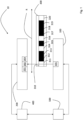
- Fig.1 shows a schematic view of an embodiment of a device 10 for determining position, length or angle.
- the device 10 initially comprises a transmission area 100 with at least one transmission element 101.
- the transmission element 101 is shown here as an example as an optical transmission element 101.
- the device 10 also comprises a receiving area 200, with several receiving elements, of which in the Fig.1 For reasons of clarity, only three receiving elements 201, 202 and 203 are shown, which are designed as photodiodes.
- the device 10 also includes a coding area 300 that includes a code word 310 with predefined sections, wherein a code word 310 with a total of ten coding sections 311 to 320 is shown as an example.
- Each of the coding sections 311 to 320 represents either a logical one or a logical zero.
- the coding sections 311, 314, 316 and 320 are shown as translucent and the coding sections 312, 313, 315, 317, 318 and 319 are shown as less or not at all translucent.
- the transmitting area 100, the receiving area 200 and the coding area 300 are arranged and designed to be movable along a direction R relative to one another, such that the receiving elements 201, 202 and 203 receive a logical one or a logical zero depending on the position of the coding area 300 and the transmitting area 100 relative to the receiving area 200. It is shown by way of example that in the current position, a light emitted by the transmitting element 101 that shines through the light-permeable coding section 311 is received by the receiving element 202 and recorded as a logical one. In a position in which the second coding section 312 is positioned between the transmitting element 101 and the receiving element 202, a logical zero would accordingly be received.
- the device 10 also comprises an evaluation unit 400 which is designed to detect a relative position of the receiving elements 201, 202, 203 and to detect and evaluate a deviation of the relative position from a target position of at least one of the receiving elements 201, 202, 203.
- the device 10 also comprises a control unit 500 which is designed to control the receiving elements 201, 202, 203 depending on the previously detected deviation.
- the control of the receiving elements 201, 202, 203 can comprise switching off at least one receiving element 202, in particular several receiving elements 202, 203 arranged next to one another.
- control of the receiving elements 201, 202, 203 can comprise a change from one receiving element 202 to another receiving element 203, in particular to an adjacent receiving element 203.
- the evaluation of the deviation can include an evaluation of a phase and/or a signal strength of the received signal.
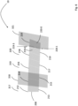
- Fig.2 shows a perspective view of an embodiment of a device 10 for position, length or angle determination according to Fig.1 .
- FIG. 1 A total of 32 receiving elements 201 to 232 are shown. These receiving elements 201 to 232 are elongated and have rounded corners. Four Receiving elements (every fourth) form a group which each receive or evaluate 90° of a phase in order to determine a position and in particular an angle.
- the receiving elements 201, 205, 209, 213, 217, 221, 225 and 229 are controlled simultaneously, then the receiving elements 202, 206, 210, 214, 218, 222, 226 and 230 simultaneously, then the receiving elements 203, 207, 211, 215, 219, 223, 227 and 231 simultaneously and then the receiving elements 204, 208, 212, 216, 220, 224, 228 and 232 simultaneously to determine the position or angle.
- FIG.1 A total of 21 code sections 311 to 331 of the coding area are shown, which form the code word and which alternate in their permeability, i.e. all odd code sections produce a logical zero and all even code sections produce a logical one.
- the code word shown is in particular an incremental code word or a code word of an incremental encoder.
- the code sections 311 to 331 are inclined or tilted to the receiving elements 201 to 231, so that in particular the code sections from 320 to 331 are no longer completely aligned with the respective receiving elements.
- the code sections 312, 314, 316 and 318 the majority of the area of the associated receiving elements from the fourth group, i.e. the receiving elements 204, 208, 212 and 216, are still filled with the permeable area, i.e.
- This position deviation can be detected by the evaluation unit and the control unit can then compensate for this misalignment by controlling the receiving elements differently, as shown in the following Fig.3 is shown.
- Fig.3 shows a detailed view of an embodiment of a device for position, length or angle determination 10 according to Fig.2 .
- Fig.3 only the section of the first 17 code sections from 311 to 327 from Fig.2 shown.
- the fourth receiving elements 204, 208, 212 and 216 from the first, second, third and fourth groups which, as in connection with Fig.2 described, are still sufficiently arranged in the respective code section 312, 314, 316 and 318, are controlled together with the third receiving elements 219, 223, 227 and 231, which are then also sufficiently arranged in the respective code section 320, 322, 324 and 326, as shown by the schematically illustrated circuitry.
- the wiring was changed in such a way that they are no longer controlled at the time of reading, i.e. they are switched off, and in contrast, the four adjacent receiving elements 219, 223, 227 and 231 from the same group are controlled, i.e. they are switched on, in order to compensate for the misalignment.
- Fig.4 shows an alternative detailed view of an embodiment of a device for position, length or angle determination 10 according to Fig.2 or according to Fig.3 .
- the last of the eight groups namely the group consisting of the four receiving elements 229, 230, 231 and 232 arranged next to each other, is no longer controlled or is switched off in order to avoid false detection and to compensate for the misalignment.
- Fig.5 shows a perspective view of an alternative embodiment of a device 10 for position, length or angle determination according to Fig.1 .
- FIG.1 A total of 20 receiving elements 201 to 220 are shown, which have a substantially rectangular shape.
- FIG.1 A total of 11 code sections 311 to 321 of the coding area are shown, which form the code word and which are designed differently in terms of their permeability.
- the code sections 311, 318 and 321 are shown as opaque, i.e. generating a zero
- the code sections 312, 313, 314, 315, 316, 317, 319 and 320 are shown as permeable, i.e. generating a one.
- the code word shown is in particular an absolute code word or a code word for an absolute encoder.
- the receiving elements are inclined or tilted in particular from receiving elements 210 upwards and the code sections from 316 upwards, so that in particular the code sections from 316 to 321 are not are no longer completely aligned with the respective receiving elements 210 to 220, so that a zero or one can no longer be reliably detected.
- This position deviation can be detected by the evaluation unit and the control unit can then compensate for this misalignment by controlling the receiving elements differently, as shown in the following Fig.6 is shown.
- Fig.6 shows a detailed view of an embodiment of a device for position, length or angle determination 10 according to Fig.5 .
- Fig.6 For example, only the section of the last five code sections from 317 to 321 and the last nine receiving elements 212 to 220 from Fig.5 shown.
- the receiving element 220 has a first receiving section 220-1, which is arranged in the lower left edge area or in the lower left corner, and a central receiving section 220-0, which takes up the majority of the area of the receiving element 220.
- the receiving element 219 is shown in such a way that it has a receiving section 219-3 in the edge region and a central receiving section 219-0, which takes up the majority of the area of the receiving element 219.
- Both the receiving section 220-1 in the edge region of the receiving element 220 and the receiving section 219-3 in the edge region of the receiving element 219 are essentially triangular, in particular in the form of a circular sector.
- the receiving section 220-1 and the receiving section 219-3 are constructed corresponding to one another.
- each of the receiving elements 212 to 220 can have at least one, in particular four, receiving sections in the edge regions as well as a central receiving section.
- a respective triangular receiving section is arranged at each corner of each receiving element, which essentially meet along a horizontal central axis of the receiving element, but are spaced apart from one another along a vertical central axis of the receiving element.
- the respective central receiving section is thus truncated diamond-shaped.
- receiving sections in the edge region can be controlled differently by the control unit.
- the receiving section 220-1 in the edge region of the receiving element 220 can be controlled together with the receiving element 219 and not together with the central receiving section 220-0 and/or the receiving section 219-3 in the edge region of the receiving element 219 can be controlled together with the receiving element 220 and not together with the central receiving section 219-0 in order to detect a position.
- Fig.5 and 6 shown with those as in Fig.2 , 3 and 4
- the reception elements shown can also be made of Fig. 2 , 3 and 4 be divided into several receiving sections.
- some, especially complete adjacent receiving elements can be made of Fig.5 and 6 can be switched on, off or changed.
- Fig.7 shows an embodiment of a method 1000 for determining position, length or angle.
- the method 1000 begins in a first step 1010 in which a transmission area, a reception area and/or a coding area of a device are moved towards each other such that receiving elements of the reception area receive a logical one or a logical zero depending on the position of the coding area and/or the transmission area relative to the reception area.
- step 1020 in which a relative position of the receiving elements is detected.
- step 1030 in which a deviation of the relative position from a desired position of at least one of the receiving elements is detected.
- step 1040 in which the receiving elements are controlled depending on the deviation.
- the method 1000 may also include an initial step (not shown) prior to step 1010 in which a Fig. 1 to 6 described device is provided.
- the previously described embodiments of the device and the method make it possible in particular to optimize the usable area of the receiving elements, especially when using different radii, without generating a significant increase in area consumption. This also reduces the manufacturing costs.
- the previously described embodiments of the device and the method make it possible in particular for the signal shape of the received signal is optimized in contrast to conventional devices and methods, in particular the harmonics are reduced when different radii are used.
- the previously described embodiments of the device and the method also make it possible in particular for the signal shape of the received signal to be optimized during coarse and fine sampling using only one code word when different radii are used.
Landscapes
- Physics & Mathematics (AREA)
- General Physics & Mathematics (AREA)
- Optical Transform (AREA)
- Transmission And Conversion Of Sensor Element Output (AREA)
Abstract
Description
- Die Erfindung betrifft eine Vorrichtung und ein Verfahren zur Erfassung einer Position, einer Länge und/oder eines Winkels.
- Geräte zur Positions-, Längen- oder Winkelbestimmung, die auch als Encoder oder Kodierer bezeichnet werden, sind Vorrichtungen, die Signale aus mechanischen Bewegungen erfassen und ausgeben können.
- Dabei gibt es sowohl Geräte, die rotatorisch ausgebildet sind, also eine Drehbewegung erfassen, als auch Geräte, die linear ausgebildet sind, also eine Längsbewegung erfassen. Diese Geräte können beispielsweise optisch, magnetisch, kapazitiv oder induktiv arbeiten und so eine Position, eine Länge oder einen Winkel erfassen.
- Dabei kann beispielsweise durch eine Montage, äußere Einflüsse oder eine Verstellung der Geräte eine Verschiebung einzelner Bauteile erfolgen, was zu einer Verfälschung der Erfassung führt.
- Es ist eine Aufgabe der vorliegenden Erfindung, eine verbesserte Vorrichtung und ein verbessertes Verfahren zur Erfassung einer Position, einer Länge und/oder eines Winkels bereitzustellen.
- Diese Aufgabe wird gelöst durch eine Vorrichtung zur Positions-, Längen- oder Winkelbestimmung, umfassend einen Sendebereich, umfassend zumindest ein Sendeelement, einen Empfangsbereich, mit mehreren Empfangselementen, einen Codierungsbereich, der ein Codewort mit vordefinierten Abschnitten umfasst, wobei der Sendebereich, der Empfangsbereich und der Codierungsbereich derart beweglich zueinander angeordnet und ausgebildet sind, dass die Empfangselemente in Abhängigkeit von der Position des Codierungsbereichs und/oder des Sendebereichs zu dem Empfangsbereich eine logische Eins oder eine logische Null empfangen.
- Die Vorrichtung umfasst auch eine Auswertungseinheit, die ausgebildet ist, eine relative Position der Empfangselemente zu erfassen und eine Abweichung der relativen Position von einer Sollposition zumindest eines der Empfangselemente auszuwerten, und eine Steuereinheit, die ausgebildet ist, die Empfangselemente in Abhängigkeit von der Abweichung anzusteuern.
- Die erfindungsgemäße Vorrichtung dient dabei zunächst dazu, eine Position, insbesondere eine Position der Empfangselemente, zu erfassen und auszuwerten. Insbesondere handelt es sich bei der erfindungsgemäßen Vorrichtung um eine Vorrichtung zur Längen- und/oder Winkelmessung, welche insbesondere basierend auf der zuvor erfassten Position ermittelt werden kann. Die Vorrichtung kann dabei beispielsweise als Encoder, insbesondere als Dreh- oder Winkelencoder bezeichnet werden.
- Die erfindungsgemäße Vorrichtung umfasst zunächst einen Sendebereich mit zumindest einem Sendeelement. Das Sendeelement ist dabei ausgebildet ein Signal auszusenden. Dabei kann das Sendeelement optisch, magnetisch, kapazitiv oder induktiv ausgebildet sein und ein entsprechendes Signal aussenden. Im Falle eines optischen Sendelements kann es sich beispielsweise um eine Halbleiterlichtquelle, insbesondere eine LED handeln. Der Sendebereich kann insbesondere mehr als ein Sendeelement aufweisen, beispielsweise zwei, vier, acht, 16 oder 32 oder mehr Sendeelemente.
- Die Vorrichtung umfasst weiter einen Empfangsbereich, mit mehreren Empfangselementen. Die Empfangselemente sind dabei ausgebildet, das von dem Sendeelement ausgesendete Signal zu empfangen. Die Empfangselemente können auch optisch, magnetisch, kapazitiv oder induktiv ausgebildet sein und ein entsprechendes Signal empfangen. Insbesondere sind die Empfangselemente korrespondierend zu dem Sendeelement ausgebildet. Im Falle eines optischen Empfangselements kann es sich beispielsweise um einen Halbleiterlichtempfänger, insbesondere eine Photodiode handeln. Der Empfangsbereich weist dabei mehrere Empfangselemente aufweisen, beispielswiese zwei, vier, acht, 16 oder 32 oder mehr Empfangselemente.
- Die Vorrichtung umfasst auch einen Codierungsbereich, der ein Codewort mit vordefinierten Abschnitten umfasst und so ein Codewort bildet. Das Codewort kann dabei aus einer vordefinierten endlichen Länge aus mehreren aufeinanderfolgenden Elementen, die eine logische Eins oder eine logische Null repräsentieren, bestehen. Der Codierungsbereich kann auch optisch, magnetisch, kapazitiv oder induktiv ausgebildet sein. Insbesondere ist der Codierungsbereich korrespondierend zu dem Sendeelement und den Empfangselementen ausgebildet. Im Falle eines optischen Codierungselements ist ein Element, das eine logische Eins repräsentiert, ein Abschnitt, der lichtdurchlässig ist, und ein Element, das eine logische Null repräsentiert, ein Abschnitt der lichtundurchlässig ist, oder andersherum, das heißt ein Element, das eine logische Null repräsentiert, ist ein Abschnitt der lichtdurchlässig ist, und ein Element, das eine logische Eins repräsentiert, ist ein Abschnitt der lichtundurchlässig ist.
- Beispielsweise umfasst das Codewort zumindest eine Eins und eine Null. Insbesondere umfasst das Codewort mehr als zwei Elemente, insbesondere vier, acht, neun, zehn, zwölf oder 16 Elemente, die aus aufeinanderfolgenden Einsen und Nullen bestehen. Bei dem Codewort kann es sich sowohl um ein Absolutcodewort als auch ein Relativcodewort bzw. ein Inkrementalcodewort handeln. Ebenso können mehrere Codewörter in dem Codierungsbereich angeordnet sein, die sowohl Absolutcodewörter als auch Relativcodewörter bzw. Inkrementalcodewörter umfassen.
- Dabei sind der Sendebereich, der Empfangsbereich und der Codierungsbereich derart beweglich zueinander angeordnet und ausgebildet sind, dass die Empfangselemente in Abhängigkeit von der Position des Codierungsbereichs und/oder des Sendebereichs zu dem Empfangsbereich zumindest eine logische Eins oder eine logische Null empfangen.
- Ein Empfangen einer logischen Eins oder einer logischen Null meint vorliegend insbesondere ein Empfangen einer von dem Sendeelement ausgesendeten und von dem Empfangselements in Abhängigkeit der Position des Codierungsbereichs empfangenen Signals, insbesondere einer Intensität, das bzw. die dann über oder unter einem Schwellenwert liegt und somit als Eins oder Null interpretiert werden kann (oder auch anders herum).
- Es kann auch aus einem einzigen Element des Codeworts eine höhere Auflösung als eine binäre Auflösung, d.h. eine Eins oder eine Null empfangen bzw. diese ausgewertet werden. So kann beispielsweise unter Verwendung eines Analog-Digital-Umsetzers eine Auflösung größer 1 Bit durch Abtastung des empfangenen Signals mit einem Analog-Digital-Umsetzer mit mehr als 1 Bit ermöglicht werden.
- Die Vorrichtung umfasst auch eine Auswertungseinheit, die ausgebildet ist, eine relative Position der Empfangselemente zu erfassen und eine Abweichung der relativen Position von einer Sollposition zumindest eines der Empfangselemente auszuwerten. Dabei kann beispielswese eine Sollposition eines jeden Empfangselements hinterlegt sein. Die Sollposition ist dabei vordefiniert und richtet sich insbesondere nach der Größe und/oder der Zusammensetzung der Komponenten der Vorrichtung, insbesondere des zuvor beschriebenen Sendebereichs, Empfangsbereichs und/oder Codierungsbereichs zueinander.
- Beispielsweise kann durch bauliche Toleranzen der Sendebereich, der Empfangsbereich und/oder der Codierungsbereich zueinander verschwenkt oder verdreht angeordnet sein oder ein vordefinierter Abstand des Sendebereich, des Empfangsbereich und/oder des Codierungsbereichs zueinander wird unterschritten oder überschritten. Es ergibt sich somit eine Fehlausrichtung des Sendebereichs, des Empfangsbereichs und/oder des Codierungsbereichs zueinander.
- Hierdurch ergibt sich, dass ein oder mehrere Empfangselemente nicht die vollständige Leistung von dem oder den Sendeelementen empfangen, wodurch eine Genauigkeit und/oder eine Reproduzierbarkeit der Positions-, Längen- oder Winkelbestimmung durch die Vorrichtung zunächst beeinträchtigt sein kann. Diese Fehlausrichtung kann die Auswertungseinheit basierend auf der Position und optional auf einer Phase und/oder einer Signalstärke des empfangenen Signals erfassen. Die Auswertungseinheit umfasst dazu eine anwendungsspezifische integrierte Schaltung (ASIC), eine feldprogrammierbare Gatteranordnung (FPGA) und/oder einen Mikrokontroller.
- Die Vorrichtung umfasst auch eine Steuereinheit, die ausgebildet ist, die Empfangselemente in Abhängigkeit von der Abweichung anzusteuern. Insbesondere ist die Steuereinheit ausgebildet, diese Fehlausrichtung zumindest teilweise zu kompensieren und/oder zu korrigieren, insbesondere durch eine - im Vergleich zu einem Zustand vor der Auswertung durch die Auswertungseinheit - geänderte Ansteuerung der Empfangselemente. Ein Ansteuern kann vorliegend insbesondere ein Beaufschlagen und/oder Nichtbeaufschlagen mit Spannung eines oder mehrerer der Empfangselemente umfassen. Alternativ oder zusätzlich können die Empfangselemente auch über eine Schaltungstechnik, wie beispielsweise eine Multiplexer angesteuert werden. Ausgestaltungen des Ansteuerns werden im Zusammenhang mit den folgenden Ausführungsformen näher erläutert werden.
- Durch diese erfindungsgemäße Vorrichtung ist es somit möglich, Fehlausrichtungen von Sendebereich, Empfangsbereich und/oder Codierungsbereich zueinander zu erkennen und zumindest teilweise zu kompensieren. Insbesondere ist es durch die erfindungsgemäße Vorrichtung möglich, die Leistung und insbesondere die Genauigkeit der Vorrichtung im Betrieb zu optimieren und die Funktion auf die baulichen Gegebenheiten der einzelnen Bereiche der Vorrichtung zueinander anzupassen.
- Durch die erfindungsgemäße Vorrichtung wird somit eine Lösung bereitgestellt, die insbesondere bei einer Winkelbestimmung die Nutzung von verschiedenen Radien ermöglicht, denn die durch die verschiedenen Radien hervorgerufene optische Verschiebung kann durch die erfindungsgemäße Vorrichtung kompensiert werden.
- Weiter werden insbesondere für Inkrementalencoder der Photodiodenstrom und damit auch die Signaleindeutigkeit erhöht. Insbesondere für Absolutencoder wird die Flankensteilheit verbessert und damit der Toleranzbereich erhöht.
- Gemäß einer Ausführungsform umfasst das Ansteuern der Empfangselemente ein Abschalten zumindest eines Empfangselements, insbesondere mehrerer nebeneinander angeordneter Empfangselemente. Hierdurch wird eine besonders einfache Kompensation ermöglicht.
- Gemäß einer Ausführungsform umfasst das Ansteuern der Empfangselemente ein Wechseln von einem Empfangselement auf ein anderes Empfangselement, insbesondere auf ein benachbartes Empfangselement. Ein Wechseln meint vorliegend insbesondere ein Wechsel der Ansteuerung von einem Empfangselement auf ein anderes Empfangselement. Beispielsweise wird zunächst das eine Empfangselement angesteuert und, wenn eine Abweichung erfasst wird, das andere, insbesondere benachbartes Empfangselement angesteuert und das eine Empfangselement nicht mehr angesteuert. Hierdurch wird eine besonders genaue Kompensation ermöglicht.
- Gemäß einer Ausführungsform umfasst zumindest ein Empfangselement zwei voneinander getrennte Empfangsabschnitte, wobei das Ansteuern der Empfangselemente ein Anschalten und/oder ein Abschalten eines Empfangsabschnitts umfasst.
- Insbesondere umfasst jedes Empfangselement zumindest zwei voneinander getrennte Empfangsabschnitte. Ein Empfangsabschnitt ist ein Teil des Empfangselement, der einzeln und unabhängig von dem anderen Empfangsabschnitt angesteuert werden kann. Hierdurch wird eine besonders genaue Kompensation ermöglicht.
- Gemäß einer Ausführungsform ist ein erster Empfangsabschnitt im Randbereich des Empfangselements angeordnet.
- Insbesondere sind ein erster Empfangsabschnitt, ein zweite Empfangsabschnitt, ein dritter Empfangsabschnitt im Randbereich eines bzw. aller Empfangselemente angeordnet, beispielsweise an vier Rändern bzw. Kanten eines Rechtecks oder Quadrats oder in vier Quadranten im Randbereich eines Kreises bzw. an dessen Umfang. Zusätzlich kann ein weiterer zentraler Empfangsabschnitt innerhalb des Randbereichs angeordnet sein.
- Hierdurch wird eine besonders flexible Kompensation ermöglicht.
- Gemäß einer Ausführungsform beträgt der erste Empfangsabschnitt eine Empfangsfläche von 10% oder weniger, insbesondere von 5% oder weniger von der gesamten Fläche des Empfangselements. Insbesondere beträgt die Fläche jedes Empfangsabschnitts weniger als 10%, insbesondere weniger als 5% der Gesamtfläche. Mit anderen Worten kann ein zentraler Empfangsabschnitt 60% oder mehr der Gesamtfläche einnehmen.
- Hierdurch wird eine besonders verlustarme Kompensation ermöglicht.
- Gemäß einer Ausführungsform weist der erste Empfangsabschnitt eine im Wesentlichen dreieckige Empfangsfläche auf. Insbesondere kann der erste Empfangsabschnitt als ein gekrümmtes und/oder abgerundetes Dreieck ausgebildet sein, wie beispielsweise ein Kreissektor. Weiter insbesondere ist der erste Empfangsabschnitt derart geformt, dass er keinen rechten Winkel aufweist.
- Dies ist insbesondere der Fall für eine im Wesentlichen rechteckige oder quadratische und/oder gekrümmt-rechteckige oder gekrümmt quadratische Form des Empfangselements. Dabei können insbesondere die Ankathete und die Gegenkathete der dreieckigen Empfangsfläche entlang einer Außenkante des Empfangselements angeordnet sein bzw. mit dieser zusammenfallen.
- Hierdurch wird eine besonders genaue Kompensation ermöglicht.
- Die Eingangs genannte Aufgabe wird ebenfalls gelöst durch ein Verfahren zur Positions-, Längen- oder Winkelbestimmung, umfassend die Schritte Bewegen eines Sendebereichs, eines Empfangsbereich und eines Codierungsbereich einer Vorrichtung derart zueinander, dass die Empfangselemente in Abhängigkeit von der Position des Codierungsbereichs und/oder des Sendebereichs zu dem Empfangsbereich eine logische Eins oder eine logische Null empfangen, Erfassen einer relativen Position der Empfangselemente, Auswerten einer Abweichung der relativen Position von einer Sollposition zumindest eines der Empfangselemente und Ansteuern der Empfangselemente in Abhängigkeit von der Abweichung.
- Bezüglich der Ausführungsformen des Verfahrens und deren Vorteile wird auf die oben in Bezug auf die Vorrichtung erläuterten Ausführungsformen und deren Vorteile verwiesen.
- Ausführungsformen der Vorrichtung und des Verfahrens zur Erfassung einer Position werden nun im Zusammenhang mit den folgenden Figuren näher erläutert. Es zeigen:
- Fig. 1
- eine schematische Ansicht einer Ausführungsform einer Vorrichtung zur Positions-, Längen- oder Winkelbestimmung;
- Fig. 2
- eine perspektivische Ansicht einer Ausführungsform einer Vorrichtung zur Positions-, Längen- oder Winkelbestimmung gemäß
Fig. 1 ; - Fig. 3
- eine Detailansicht einer Ausführungsform einer Vorrichtung zur Positions-, Längen- oder Winkelbestimmung gemäß
Fig. 2 ; - Fig. 4
- eine Detailansicht einer alternativem Ausführungsform einer Vorrichtung zur Positions-, Längen- oder Winkelbestimmung gemäß
Fig. 2 - Fig. 5
- eine perspektivische Ansicht einer alternativen Ausführungsform einer Vorrichtung zur Positions-, Längen- oder Winkelbestimmung gemäß
Fig. 1 ; - Fig. 6
- eine Detailansicht einer Ausführungsform einer Vorrichtung zur Positions-, Längen- oder Winkelbestimmung gemäß von
Fig. 4 ; und - Fig. 7
- eine Ausführungsform eines Verfahrens zur Positions-, Längen- oder Winkelbestimmung.
- Dabei bezeichnen gleiche Bezugszeichen gleiche oder ähnliche Merkmale.
-
Fig. 1 zeigt eine schematische Ansicht einer Ausführungsform einer Vorrichtung 10 zur Positions-, Längen- oder Winkelbestimmung. - Die Vorrichtung 10 umfasst zunächst einen Sendebereich 100 mit zumindest einem Sendeelement 101. Das Sendeelement 101 ist hier beispielhaft als optisches Sendelement 101 gezeigt.
- Die Vorrichtung 10 umfasst auch einen Empfangsbereich 200, mit mehrere Empfangselementen, wovon in der
Fig. 1 aus Gründen der Übersichtlichkeit lediglich drei Empfangselemente 201, 202 und 203 abgebildet sind, die beispielhaft als Photodioden ausgebildet sind. - Die Vorrichtung 10 umfasst auch einen Codierungsbereich 300, der ein Codewort 310 mit vordefinierten Abschnitten umfasst, wobei beispielhaft ein Codewort 310 mit insgesamt zehn Codierungsabschnitten 311 bis 320 gezeigt sind. Jeder der Codierungsabschnitte 311 bis 320 stellt entweder eine logische Eins oder eine logische Null dar. Beispielhaft sind hier die Codierungsabschnitte 311, 314, 316 und 320 als lichtdurchlässig gezeigt und die Codierungsabschnitte 312, 313, 315, 317, 318 und 319 als weniger oder gar nicht lichtdurchlässig gezeigt.
- Dabei sind der Sendebereich 100, der Empfangsbereich 200 und der Codierungsbereich 300 derart beweglich entlang einer Richtung R zueinander angeordnet und ausgebildet, sodass die Empfangselemente 201, 202 und 203 in Abhängigkeit von der Position des Codierungsbereichs 300 und des Sendebereichs 100 zu dem Empfangsbereich 200 eine logische Eins oder eine logische Null empfangen. Dabei ist beispielhaft gezeigt, dass in der gegenwärtigen Position, ein von dem Sendeelement 101 ausgesandtes Licht, das durch den lichtdurchlässigen Codierungsabschnitt 311 durchscheint, von dem Empfangselement 202 empfange und als logische Eins erfasst wird. Bei einer Position, in der der zweite Codierungsabschnitt 312 zwischen Sendeelement 101 und Empfangselement 202 positioniert ist, würde dementsprechend eine logische Null empfangen werden.
- Die Vorrichtung 10 umfasst auch eine Auswertungseinheit 400, die ausgebildet ist, eine relative Position der Empfangselemente 201, 202, 203 zu erfassen und eine Abweichung der relativen Position von einer Sollposition zumindest eines der Empfangselemente 201, 202, 203 zu erfassen und auszuwerten.
- Die Vorrichtung 10 umfasst auch eine Steuereinheit 500, die ausgebildet ist, die Empfangselemente 201, 202, 203 in Abhängigkeit von der zuvor erfassten Abweichung anzusteuern.
- Das Ansteuern der Empfangselemente 201, 202, 203 kann dabei ein Abschalten zumindest eines Empfangselements 202, insbesondere mehrerer nebeneinander angeordneter Empfangselemente 202, 203 umfassen.
- Alternativ oder zusätzlich kann das Ansteuern der Empfangselemente 201, 202, 203 ein Wechseln von einem Empfangselement 202 auf ein anderes Empfangselement 203, insbesondere auf ein benachbartes Empfangselement 203 umfassen.
- Das Auswerten der Abweichung kann dabei ein Auswerten einer Phase und/oder einer Signalstärke des empfangenen Signals umfassen.
- Verschiedene Arten der Ansteuerung werden nun im Zusammenhang mit den folgenden
Fig. 2 bis 6 beschrieben. -
Fig. 2 zeigt eine perspektivische Ansicht einer Ausführungsform einer Vorrichtung 10 zur Positions-, Längen- oder Winkelbestimmung gemäßFig. 1 . - Dabei sind abweichend zu
Fig. 1 insgesamt 32 Empfangselemente 201 bis 232 abgebildet. Diese Empfangselemente 201 bis 232 sind dabei beispielhaft langgesstreckt und mit abgerundeten Ecken ausgebildet. Dabei bilden immer vier Empfangselemente (jedes vierte) eine Gruppe, die jeweils 90° einer Phase empfangen bzw. auswerten um eine Position und insbesondere einen Winkel zu ermitteln. - Es werden also zunächst die Empfangselemente 201, 205, 209, 213, 217, 221, 225 und 229 gleichzeitig angesteuert, dann die Empfangselemente 202, 206, 210, 214, 218, 222, 226 und 230 gleichzeitig, dann die Empfangselemente 203, 207, 211, 215, 219, 223, 227 und 231 gleichzeitig und dann die Empfangselemente 204, 208, 212, 216, 220, 224, 228 und 232 gleichzeitig, um die Position bzw. den Winkel zu ermitteln.
- Ebenfalls abweichend zu
Fig. 1 sind insgesamt 21 Codeabschnitte 311 bis 331 des Codierungsbereichs abgebildet, die das Codewort bilden, und die sich in ihrer Durchlässigkeit abwechseln, also alle ungeraden Codeabschnitte eine logische Null erzeugen und alle gerade Codeabschnitte eine logische Eins erzeugen. Bei dem gezeigten Codewort handelt es sich insbesondere um ein Inkrementalcodewort bzw. um ein Codewort eines Inkrementalencoders. - Nicht abgebildet sind in dieser
Fig. 2 aus Gründen der Übersichtlichkeit der Sendebereich, die Auswertungseinheit und die Steuereinheit, wie inFig. 1 gezeigt. - Wie in
Fig. 2 zu erkennen ist, sind die Codeabschnitte 311 bis 331 zu den Empfangselemente 201 bis 231 geneigt bzw. gekippt, sodass insbesondere die Codeabschnitte von 320 bis 331 nicht mehr vollständig mit den jeweiligen Empfangselementen ausgerichtet sind. Insbesondere sind, während in den Codeabschnitten 312, 314, 316 und 318 noch der überwiegende Teil der Fläche der dazugehörigen Empfangselemente aus der vierten Gruppe, d.h. die Empfangselemente 204, 208, 212 und 216 von dem durchlässigen Bereich erfüllt sind, also eine Eins noch überwiegend wahrscheinlich erkannt werden kann, in den darauffolgenden Codeabschnitten 320, 322, 324 und 326 aufgrund der Fehlausrichtung die Empfangselemente aus der vierten Gruppe 220, 224, 228 und 232 bereits deutlich oder sogar überwiegend von den undurchlässigen Bereichen, d.h. den danebenliegenden Codeabschnitten 321, 323, 325 und 327 verdeckt, sodass eine Eins nicht mehr sicher erkannt werden kann. - Diese Positionsabweichung kann von der Auswertungseinheit erkannt werden und die Steuereinheit kann diese Fehlausrichtung sodann kompensieren, indem sie die Empfangselemente anders ansteuert, wie dies in der folgenden
Fig. 3 gezeigt ist. -
Fig. 3 zeigt eine Detailansicht einer Ausführungsform einer Vorrichtung zur Positions-, Längen- oder Winkelbestimmung 10 gemäßFig. 2 . - Dabei ist in
Fig. 3 nur der Abschnitt der ersten 17 Codeabschnitte von 311 bis 327 ausFig. 2 gezeigt. - Dabei ist sichtbar, dass die vierten Empfangselemente 204, 208, 212 und 216 aus der ersten, zweiten, dritten und vierten Gruppe, die, wie im Zusammenhang mit
Fig. 2 beschrieben, noch ausreichend in dem jeweiligen Codeabschnitt 312, 314, 316 und 318 angeordnet sind, zusammen mit den dritten Empfangselementen 219, 223, 227 und 231 angesteuert werden, die dann ebenfalls ausreichend in dem jeweiligen Codeabschnitt 320, 322, 324 und 326 angeordnet sind, wie dies über die schematisch dargestellte Verschaltung dargestellt wird. - Mit anderen Worten wurden für insgesamt vier Empfangselemente 220, 224, 228 und 232 aus vier aufeinanderfolgenden Gruppen die Verschaltung derart geändert, dass diese zum Auslesezeitpunkt nicht mehr angesteuert werden, also abgeschaltet werden, und im Gegensatz dazu die jeweils benachbarten vier Empfangselemente 219, 223, 227 und 231 aus derselben Gruppe angesteuert werden, diese also angeschaltet werden, um die Fehlausrichtung zu kompensieren.
-
Fig. 4 zeigt eine alternative Detailansicht einer Ausführungsform einer Vorrichtung zur Positions-, Längen- oder Winkelbestimmung 10 gemäßFig. 2 bzw. gemäßFig. 3 . - Dabei ist ersichtlich, dass die letzte der acht Gruppen, nämlich die Gruppe bestehend aus den vier nebeneinander angeordneten Empfangselementen 229, 230, 231 und 232 gar nicht mehr angesteuert wird bzw. abgeschaltet wird, um so eine Fehlerkennung zu vermeiden und die Fehlausrichtung zu kompensieren.
-
Fig. 5 zeigt eine perspektivische Ansicht einer alternativen Ausführungsform einer Vorrichtung 10 zur Positions-, Längen- oder Winkelbestimmung gemäßFig. 1 . - Dabei sind abweichend zu
Fig. 1 insgesamt 20 Empfangselemente 201 bis 220 abgebildet, die eine im Wesentlichen rechteckige Form aufweisen. - Ebenfalls abweichend zu
Fig. 1 sind insgesamt 11 Codeabschnitte 311 bis 321 des Codierungsbereichs abgebildet, die das Codewort bilden, und die in ihrer Durchlässigkeit unterschiedlich ausgebildet sind. So sind beispielhaft die Codeabschnitte 311, 318 und 321 als undurchlässig, also eine Null erzeugend, und die Codeabschnitte 312, 313, 314, 315, 316, 317, 319 und 320 als durchlässig, also eine Eins erzeugend, abgebildet. Bei dem gezeigten Codewort handelt es sich insbesondere um ein Absolutcodewort bzw. um ein Codewort für einen Absolutcodierer - Nicht abgebildet sind auch in dieser
Fig. 5 aus Gründen der Übersichtlichkeit der Sendebereich, die Auswertungseinheit und die Steuereinheit, wie inFig. 1 gezeigt. - Wie in
Fig. 5 zu erkennen ist, sind die Empfangselemente insbesondere ab Empfangselemente 210 aufsteigend und die Codeabschnitte ab 316 aufsteigend geneigt bzw. gekippt, sodass insbesondere die Codeabschnitte von 316 bis 321 nicht mehr vollständig mit den jeweiligen Empfangselementen 210 bis 220 ausgerichtet sind, sodass eine Null oder Eins nicht mehr sicher erkannt werden kann. - Diese Positionsabweichung kann von der Auswertungseinheit erkannt werden und die Steuereinheit kann diese Fehlausrichtung sodann kompensieren, indem sie die Empfangselemente anders ansteuert, wie dies in der folgenden
Fig. 6 gezeigt ist. -
Fig. 6 zeigt eine Detailansicht einer Ausführungsform einer Vorrichtung zur Positions-, Längen- oder Winkelbestimmung 10 gemäßFig. 5 . - Dabei ist in
Fig. 6 beispielhaft nur der Abschnitt der letzten fünf Codeabschnitte von 317 bis 321 und der letzten neun Empfangselemente 212 bis 220 ausFig. 5 gezeigt. - Dabei ist sichtbar, dass die letzten Empfangselemente 219 und 220 beispielhaft in mehrere Empfangsabschnitte unterteilt sind. So weist das Empfangselement 220 einen ersten Empfangsabschnitt 220-1, der am unteren linken Randbereich bzw. in der unteren linken Ecke angeordnet ist, und einen zentralen Empfangsabschnitt 220-0, der den überwiegenden Teil der Fläche des Empfangselements 220 einnimmt.
- Ebenso ist das Empfangselement 219 derart dargestellt, dass es einen Empfangsabschnitt 219-3 im Randbereich aufweist sowie einen zentralen Empfangsabschnitt 219-0, der den überwiegenden Teil der Fläche des Empfangselements 219 einnimmt.
- Sowohl der Empfangsabschnitt 220-1 im Randbereich des Empfangselements 220 als auch der Empfangsabschnitt 219-3 im Randbereich des Empfangselements 219 sind dabei im Wesentlichen dreieckig, insbesondere in Form eines Kreissektors ausgebildet. Insbesondere sind der Empfangsabschnitt 220-1 und der Empfangsabschnitt 219-3 korrespondierend zueinander aufgebaut.
- Dabei versteht es sich, dass jedes der Empfangselemente 212 bis 220 zumindest einen, insbesondere vier Empfangsabschnitte in den Randbereichen sowie einen zentralen Empfangsabschnitt aufweisen kann. Insbesondere sind an jeder Ecke jedes Empfangselements ein jeweiliger dreieckiger Empfangsabschnitt angeordnet, die sich im Wesentlichen entlang einer horizontalen Mittelachse des Empfangselements treffen, entlang einer vertikalen Mittelachse des Empfangselements jedoch voneinander beabstandet sind. Weiter insbesondere ist der jeweilige zentrale Empfangsabschnitt somit rautenstumpfförmig ausgebildet.
- Diese Empfangsabschnitte im Randbereich können von der Steuereinheit abweichend angesteuert werden. Insbesondere kann beispielsweise der Empfangsabschnitt 220-1 im Randbereich des Empfangselements 220 zusammen mit dem Empfangselement 219 und nicht zusammen mit dem zentralen Empfangsabschnitt 220-0 angesteuert werden und/oder der Empfangsabschnitt 219-3 im Randbereich des Empfangselements 219 zusammen mit dem Empfangselement 220 und nicht zusammen mit dem zentralen Empfangsabschnitt 219-0 angesteuert werden, um eine Position zu erfassen.
- Es versteht sich, dass die Ausführungsbeispiele wie in
Fig. 5 und6 gezeigt mit denjenigen wie inFig. 2 ,3 und4 gezeigt, kombiniert werden können. Insbesondere können auch die gezeigten Empfangselemente ausFig. 2 ,3 und4 in mehrere Empfangsabschnitte unterteilt sein. Ebenso können einige, insbesondere vollständige benachbarte Empfangselemente ausFig. 5 und6 an-, um- bzw. abgeschaltet werden. -
Fig. 7 zeigt eine Ausführungsform eines Verfahrens 1000 zur Positions-, Längen- oder Winkelbestimmung. - Das Verfahren 1000 beginnt in einem ersten Schritt 1010, in dem ein Sendebereich, ein Empfangsbereich und/oder ein Codierungsbereich einer Vorrichtung derart zueinander bewegt werden, dass Empfangselemente des Empfangsbereich in Abhängigkeit von der Position des Codierungsbereichs und/oder des Sendebereichs zu dem Empfangsbereich eine logische Eins oder eine logische Null empfangen.
- Das Verfahren 1000 fährt fort mit dem Schritt 1020, in dem eine relativen Position der Empfangselemente erfasst wird.
- Das Verfahren fährt fort mit dem Schritt 1030, in dem eine Abweichung der relativen Position von einer Sollposition zumindest eines der Empfangselemente erfasst wird.
- Das Verfahren 1000 fährt fort mit dem Schritt 1040, in dem die Empfangselemente in Abhängigkeit von der Abweichung angesteuert werden.
- Das Verfahren 1000 kann auch einen nicht abgebildeten Initialschritt vor dem Schritt 1010 umfassen, in dem eine wie im Zusammenhang mit einer der
Fig. 1 bis 6 beschriebene Vorrichtung bereitgestellt wird. - Durch die zuvor beschriebenen Ausführungsformen der Vorrichtung und des Verfahrens wird es insbesondere ermöglicht, dass die nutzbare Fläche der Empfangselemente optimiert wird, insbesondere bei der Nutzung von unterschiedlichen Radien, ohne einen signifikanten Flächenmehrverbrauch zu erzeugen. Hierdurch werden auch die Herstellungskosten reduziert.
- Ebenso wird es durch die zuvor beschriebenen Ausführungsformen der Vorrichtung und des Verfahrens insbesondere ermöglicht, dass die Signalform des empfangenen Signals im Gegensatz zu herkömmlichen Vorrichtungen und Verfahren optimiert wird, insbesondere die Oberschwingungen reduziert werden, wenn unterschiedliche Radien verwendet werden.
- Auch wird es durch die zuvor beschriebenen Ausführungsformen der Vorrichtung und des Verfahrens insbesondere ermöglicht, dass die Signalform des empfangenen Signals bei einer Grob- und Feinabtastung bei Nutzung nur eines Codeworts optimiert wird, wenn unterschiedliche Radien verwendet werden.
-
- 10
- Vorrichtung
- 100
- Sendebereich
- 101
- Sendeelement
- 200
- Empfangsbereich
- 201
- Empfangselement
- 202
- Empfangselement
- 203
- Empfangselement
- 204
- Empfangselement
- 205
- Empfangselement
- 206
- Empfangselement
- 207
- Empfangselement
- 208
- Empfangselement
- 209
- Empfangselement
- 210
- Empfangselement
- 211
- Empfangselement
- 212
- Empfangselement
- 213
- Empfangselement
- 214
- Empfangselement
- 215
- Empfangselement
- 216
- Empfangselement
- 217
- Empfangselement
- 218
- Empfangselement
- 219
- Empfangselement
- 219-0
- Empfangsabschnitt
- 219-3
- Empfangsabschnitt
- 220
- Empfangselement
- 220-0
- Empfangsabschnitt
- 220-1
- Empfangsabschnitt
- 221
- Empfangselement
- 222
- Empfangselement
- 223
- Empfangselement
- 224
- Empfangselement
- 225
- Empfangselement
- 226
- Empfangselement
- 227
- Empfangselement
- 228
- Empfangselement
- 229
- Empfangselement
- 230
- Empfangselement
- 231
- Empfangselement
- 232
- Empfangselement
- 300
- Codierungsbereich
- 310
- Codewort
- 311
- Codewortabschnitt
- 312
- Codewortabschnitt
- 313
- Codewortabschnitt
- 314
- Codewortabschnitt
- 315
- Codewortabschnitt
- 316
- Codewortabschnitt
- 317
- Codewortabschnitt
- 318
- Codewortabschnitt
- 319
- Codewortabschnitt
- 320
- Codewortabschnitt
- 400
- Auswertungseinheit
- 500
- Steuereinheit
- 1000
- Verfahren
- 1010
- Verfahrensschritt
- 1020
- Verfahrensschritt
- 1030
- Verfahrensschritt
- 1040
- Verfahrensschritt
- R
- Richtung
Claims (12)
- Vorrichtung (10) zur Positions-, Längen- oder Winkelbestimmung, umfassend:- einen Sendebereich (100), umfassend zumindest ein Sendeelement (101);- einen Empfangsbereich (200), umfassend mehrere Empfangselemente (201...232);- einen Codierungsbereich (300), der ein Codewort (310) mit vordefinierten Abschnitten (311...320) umfasst;- wobei der Sendebereich (100), der Empfangsbereich (200) und der Codierungsbereich (300) derart beweglich zueinander angeordnet und ausgebildet sind, dass die Empfangselemente (201...232) in Abhängigkeit von der Position des Codierungsbereichs (300) und/oder des Sendebereichs (100) zu dem Empfangsbereich (200) eine logische Eins oder eine logische Null empfangen;- eine Auswertungseinheit (400), die ausgebildet ist, eine relative Position der Empfangselemente (201...232) zu erfassen und eine Abweichung der relativen Position von einer Sollposition zumindest eines der Empfangselemente (201...232) auszuwerten; und- eine Steuereinheit (500), die ausgebildet ist, die Empfangselemente (201...232) in Abhängigkeit von der Abweichung anzusteuern.
- Vorrichtung (10) nach Anspruch 1,
wobei das Ansteuern der Empfangselemente (201...232) ein Abschalten zumindest eines Empfangselements (232) umfasst. - Vorrichtung nach einem der vorstehenden Ansprüche,
wobei das Ansteuern der Empfangselemente (201 ...232) ein Abschalten mehrerer nebeneinander angeordneter Empfangselemente (229...232) umfasst. - Vorrichtung nach einem der vorstehenden Ansprüche,
wobei das Ansteuern der Empfangselemente (201 ...232) ein Wechseln von einem Empfangselement (215) auf ein anderes Empfangselement (216) umfasst. - Vorrichtung (10) nach Anspruch 5,
wobei das Wechseln ein Wechseln von einem Empfangselement (215) auf ein benachbartes Empfangselement (216) umfasst. - Vorrichtung (10) nach einem der vorstehenden Ansprüche,
wobei zumindest ein Empfangselement zwei voneinander getrennte Empfangsabschnitte (220-0, 220-1) umfasst und wobei das Ansteuern der Empfangselemente (201 ...232) ein Anschalten und/oder ein Abschalten eines Empfangsabschnitts (220-0, 220-1) umfasst. - Vorrichtung (10) nach Anspruch 6, wobei ein erster Empfangsabschnitt (220-1) im Randbereich des Empfangselements (220) angeordnet ist.
- Vorrichtung (10) nach Anspruch 7, wobei der erste Empfangsabschnitt (220-1) eine Empfangsfläche von 10% oder weniger von der Fläche des Empfangselements (220) umfasst.
- Vorrichtung (10) nach Anspruch 7 oder 8, wobei der erste Empfangsabschnitt (220-1) eine im Wesentlichen dreieckige Empfangsfläche aufweist.
- Vorrichtung (10) nach einem der vorstehenden Ansprüche,
wobei das Auswerten der Abweichung ein Auswerten einer Phase umfasst. - Vorrichtung (10) nach einem der vorstehenden Ansprüche,
wobei das Auswerten der Abweichung ein Auswerten einer Signalstärke umfasst. - Verfahren (1000) zur Positions-, Längen- oder Winkelbestimmung, umfassend die Schritte:- Bewegen (1010) eines Sendebereichs (100), eines Empfangsbereich (200) und/oder eines Codierungsbereich (300) einer Vorrichtung (10) derart zueinander, dass Empfangselemente (210) des Empfangsbereich in Abhängigkeit von der Position des Codierungsbereichs (300) und/oder des Sendebereichs (100) zu dem Empfangsbereich (200) eine logische Eins oder eine logische Null empfangen;- Erfassen (1020) einer relativen Position der Empfangselemente (210)- Auswerten (1030) einer Abweichung der relativen Position von einer Sollposition zumindest eines der Empfangselemente (210); und- Ansteuern (1040) der Empfangselemente (210) in Abhängigkeit von der Abweichung.
Priority Applications (1)
| Application Number | Priority Date | Filing Date | Title |
|---|---|---|---|
| EP22209571.3A EP4375621B1 (de) | 2022-11-25 | 2022-11-25 | Vorrichtung und verfahren zur positions-, längen- oder winkelbestimmung |
Applications Claiming Priority (1)
| Application Number | Priority Date | Filing Date | Title |
|---|---|---|---|
| EP22209571.3A EP4375621B1 (de) | 2022-11-25 | 2022-11-25 | Vorrichtung und verfahren zur positions-, längen- oder winkelbestimmung |
Publications (2)
| Publication Number | Publication Date |
|---|---|
| EP4375621A1 true EP4375621A1 (de) | 2024-05-29 |
| EP4375621B1 EP4375621B1 (de) | 2024-10-09 |
Family
ID=84363138
Family Applications (1)
| Application Number | Title | Priority Date | Filing Date |
|---|---|---|---|
| EP22209571.3A Active EP4375621B1 (de) | 2022-11-25 | 2022-11-25 | Vorrichtung und verfahren zur positions-, längen- oder winkelbestimmung |
Country Status (1)
| Country | Link |
|---|---|
| EP (1) | EP4375621B1 (de) |
Citations (6)
| Publication number | Priority date | Publication date | Assignee | Title |
|---|---|---|---|---|
| DE19518664C1 (de) * | 1995-05-20 | 1996-05-23 | Christian Dipl Ing Rathjen | Verfahren zur Bestimmung der Position zweier zueinander bewegbarer Körper |
| DE19803249A1 (de) * | 1997-01-29 | 1998-08-13 | Mitutoyo Corp | Mit induziertem Strom arbeitender Absolutpositionswandler, der mit einer Codespur-Skala und einem Lesekopf ausgestattet ist |
| EP1630363A1 (de) * | 2004-08-28 | 2006-03-01 | LuK Lamellen und Kupplungsbau Beteiligungs KG | Verfahren zum Bestimmen der Phasenlage einer Nockenwelle einer Brennkraftmaschine |
| DE102007050253A1 (de) * | 2007-10-20 | 2009-04-23 | Dr. Johannes Heidenhain Gmbh | Detektorelement-Array für eine optische Positionsmesseinrichtung |
| DE102012222319A1 (de) * | 2012-12-05 | 2014-06-05 | Dr. Johannes Heidenhain Gmbh | Positionsmesseinrichtung |
| WO2022185825A1 (ja) * | 2021-03-01 | 2022-09-09 | 村田機械株式会社 | 変位検出装置 |
-
2022
- 2022-11-25 EP EP22209571.3A patent/EP4375621B1/de active Active
Patent Citations (6)
| Publication number | Priority date | Publication date | Assignee | Title |
|---|---|---|---|---|
| DE19518664C1 (de) * | 1995-05-20 | 1996-05-23 | Christian Dipl Ing Rathjen | Verfahren zur Bestimmung der Position zweier zueinander bewegbarer Körper |
| DE19803249A1 (de) * | 1997-01-29 | 1998-08-13 | Mitutoyo Corp | Mit induziertem Strom arbeitender Absolutpositionswandler, der mit einer Codespur-Skala und einem Lesekopf ausgestattet ist |
| EP1630363A1 (de) * | 2004-08-28 | 2006-03-01 | LuK Lamellen und Kupplungsbau Beteiligungs KG | Verfahren zum Bestimmen der Phasenlage einer Nockenwelle einer Brennkraftmaschine |
| DE102007050253A1 (de) * | 2007-10-20 | 2009-04-23 | Dr. Johannes Heidenhain Gmbh | Detektorelement-Array für eine optische Positionsmesseinrichtung |
| DE102012222319A1 (de) * | 2012-12-05 | 2014-06-05 | Dr. Johannes Heidenhain Gmbh | Positionsmesseinrichtung |
| WO2022185825A1 (ja) * | 2021-03-01 | 2022-09-09 | 村田機械株式会社 | 変位検出装置 |
Also Published As
| Publication number | Publication date |
|---|---|
| EP4375621B1 (de) | 2024-10-09 |
Similar Documents
| Publication | Publication Date | Title |
|---|---|---|
| DE3910873C2 (de) | ||
| EP2072965B1 (de) | Positionsmesseinrichtung und Verfahren zur absoluten Positionsbestimmung | |
| DE3144334C2 (de) | Wegmeßeinrichtung mit Referenzmarken | |
| AT509101B1 (de) | Induktive messeinrichtung für längen- und winkelerfassung | |
| EP1222471B1 (de) | Gebersystem mit einem beschleunigungsgeber und einem positionsgeber | |
| EP0172323A1 (de) | Messeinrichtung | |
| EP4242595B1 (de) | Vorrichtung und verfahren zur positions-, längen- oder winkelbestimmung | |
| EP0118673A2 (de) | Messeinrichtung | |
| DE2501373B2 (de) | Anordnung zur Winkel- oder Längenmessung | |
| CH672185A5 (de) | ||
| AT410485B (de) | Positionsmesseinrichtung | |
| EP2869031B1 (de) | Positionsmesseinrichtung | |
| DE3340924A1 (de) | Verfahren und vorrichtung zum beruehrungslosen erfassen der bewegung eines objektes | |
| EP2342539B1 (de) | Absolute positionsmessvorrichtung | |
| EP4375621B1 (de) | Vorrichtung und verfahren zur positions-, längen- oder winkelbestimmung | |
| DE102017204871A1 (de) | Energiesparendes Positionsbestimmungsverfahren | |
| EP1074819B1 (de) | Lenkwinkelsensor | |
| DE102006010161B4 (de) | Codestruktur für eine Positionsmesseinrichtung und Positionsmesseinrichtung mit einer solchen Codestruktur | |
| EP4174446B1 (de) | Gebervorrichtung und verfahren zur bestimmung einer absolutposition | |
| DE102017118509B4 (de) | Zylinder mit einer Kolbenstange und einem optischen Positionsmesser | |
| DE102021110583B4 (de) | Gebervorrichtung und Verfahren zur Bestimmung einer Absolutposition | |
| DE1274363B (de) | Einrichtung zum absolut-digitalen Messen | |
| DE102014200945A1 (de) | Vorrichtung zur Feststellung von diskreten Positionen eines bewegbaren Schaltelementes | |
| DE102023134633B3 (de) | Vorrichtung zur positions-, längen- oder winkelbestimmung | |
| EP4293323B1 (de) | Vorrichtung und verfahren zur überwachung einer funktionalität eines geräts zur positions-, längen- oder winkelbestimmung |
Legal Events
| Date | Code | Title | Description |
|---|---|---|---|
| PUAI | Public reference made under article 153(3) epc to a published international application that has entered the european phase |
Free format text: ORIGINAL CODE: 0009012 |
|
| STAA | Information on the status of an ep patent application or granted ep patent |
Free format text: STATUS: EXAMINATION IS IN PROGRESS |
|
| 17P | Request for examination filed |
Effective date: 20240119 |
|
| AK | Designated contracting states |
Kind code of ref document: A1 Designated state(s): AL AT BE BG CH CY CZ DE DK EE ES FI FR GB GR HR HU IE IS IT LI LT LU LV MC ME MK MT NL NO PL PT RO RS SE SI SK SM TR |
|
| GRAP | Despatch of communication of intention to grant a patent |
Free format text: ORIGINAL CODE: EPIDOSNIGR1 |
|
| STAA | Information on the status of an ep patent application or granted ep patent |
Free format text: STATUS: GRANT OF PATENT IS INTENDED |
|
| INTG | Intention to grant announced |
Effective date: 20240625 |
|
| GRAS | Grant fee paid |
Free format text: ORIGINAL CODE: EPIDOSNIGR3 |
|
| GRAA | (expected) grant |
Free format text: ORIGINAL CODE: 0009210 |
|
| STAA | Information on the status of an ep patent application or granted ep patent |
Free format text: STATUS: THE PATENT HAS BEEN GRANTED |
|
| AK | Designated contracting states |
Kind code of ref document: B1 Designated state(s): AL AT BE BG CH CY CZ DE DK EE ES FI FR GB GR HR HU IE IS IT LI LT LU LV MC ME MK MT NL NO PL PT RO RS SE SI SK SM TR |
|
| REG | Reference to a national code |
Ref country code: CH Ref legal event code: EP |
|
| REG | Reference to a national code |
Ref country code: DE Ref legal event code: R096 Ref document number: 502022001855 Country of ref document: DE |
|
| REG | Reference to a national code |
Ref country code: IE Ref legal event code: FG4D Free format text: LANGUAGE OF EP DOCUMENT: GERMAN |
|
| REG | Reference to a national code |
Ref country code: LT Ref legal event code: MG9D |
|
| REG | Reference to a national code |
Ref country code: NL Ref legal event code: MP Effective date: 20241009 |
|
| PG25 | Lapsed in a contracting state [announced via postgrant information from national office to epo] |
Ref country code: NL Free format text: LAPSE BECAUSE OF FAILURE TO SUBMIT A TRANSLATION OF THE DESCRIPTION OR TO PAY THE FEE WITHIN THE PRESCRIBED TIME-LIMIT Effective date: 20241009 |
|
| PG25 | Lapsed in a contracting state [announced via postgrant information from national office to epo] |
Ref country code: NL Free format text: LAPSE BECAUSE OF FAILURE TO SUBMIT A TRANSLATION OF THE DESCRIPTION OR TO PAY THE FEE WITHIN THE PRESCRIBED TIME-LIMIT Effective date: 20241009 |
|
| PG25 | Lapsed in a contracting state [announced via postgrant information from national office to epo] |
Ref country code: IS Free format text: LAPSE BECAUSE OF FAILURE TO SUBMIT A TRANSLATION OF THE DESCRIPTION OR TO PAY THE FEE WITHIN THE PRESCRIBED TIME-LIMIT Effective date: 20250209 Ref country code: HR Free format text: LAPSE BECAUSE OF FAILURE TO SUBMIT A TRANSLATION OF THE DESCRIPTION OR TO PAY THE FEE WITHIN THE PRESCRIBED TIME-LIMIT Effective date: 20241009 Ref country code: PT Free format text: LAPSE BECAUSE OF FAILURE TO SUBMIT A TRANSLATION OF THE DESCRIPTION OR TO PAY THE FEE WITHIN THE PRESCRIBED TIME-LIMIT Effective date: 20250210 |
|
| PG25 | Lapsed in a contracting state [announced via postgrant information from national office to epo] |
Ref country code: FI Free format text: LAPSE BECAUSE OF FAILURE TO SUBMIT A TRANSLATION OF THE DESCRIPTION OR TO PAY THE FEE WITHIN THE PRESCRIBED TIME-LIMIT Effective date: 20241009 |
|
| PG25 | Lapsed in a contracting state [announced via postgrant information from national office to epo] |
Ref country code: BG Free format text: LAPSE BECAUSE OF FAILURE TO SUBMIT A TRANSLATION OF THE DESCRIPTION OR TO PAY THE FEE WITHIN THE PRESCRIBED TIME-LIMIT Effective date: 20241009 |
|
| PG25 | Lapsed in a contracting state [announced via postgrant information from national office to epo] |
Ref country code: ES Free format text: LAPSE BECAUSE OF FAILURE TO SUBMIT A TRANSLATION OF THE DESCRIPTION OR TO PAY THE FEE WITHIN THE PRESCRIBED TIME-LIMIT Effective date: 20241009 |
|
| PG25 | Lapsed in a contracting state [announced via postgrant information from national office to epo] |
Ref country code: NO Free format text: LAPSE BECAUSE OF FAILURE TO SUBMIT A TRANSLATION OF THE DESCRIPTION OR TO PAY THE FEE WITHIN THE PRESCRIBED TIME-LIMIT Effective date: 20250109 |
|
| PG25 | Lapsed in a contracting state [announced via postgrant information from national office to epo] |
Ref country code: LV Free format text: LAPSE BECAUSE OF FAILURE TO SUBMIT A TRANSLATION OF THE DESCRIPTION OR TO PAY THE FEE WITHIN THE PRESCRIBED TIME-LIMIT Effective date: 20241009 Ref country code: GR Free format text: LAPSE BECAUSE OF FAILURE TO SUBMIT A TRANSLATION OF THE DESCRIPTION OR TO PAY THE FEE WITHIN THE PRESCRIBED TIME-LIMIT Effective date: 20250110 |
|
| PG25 | Lapsed in a contracting state [announced via postgrant information from national office to epo] |
Ref country code: PL Free format text: LAPSE BECAUSE OF FAILURE TO SUBMIT A TRANSLATION OF THE DESCRIPTION OR TO PAY THE FEE WITHIN THE PRESCRIBED TIME-LIMIT Effective date: 20241009 |
|
| PG25 | Lapsed in a contracting state [announced via postgrant information from national office to epo] |
Ref country code: RS Free format text: LAPSE BECAUSE OF FAILURE TO SUBMIT A TRANSLATION OF THE DESCRIPTION OR TO PAY THE FEE WITHIN THE PRESCRIBED TIME-LIMIT Effective date: 20250109 |
|
| PG25 | Lapsed in a contracting state [announced via postgrant information from national office to epo] |
Ref country code: SM Free format text: LAPSE BECAUSE OF FAILURE TO SUBMIT A TRANSLATION OF THE DESCRIPTION OR TO PAY THE FEE WITHIN THE PRESCRIBED TIME-LIMIT Effective date: 20241009 |
|
| PG25 | Lapsed in a contracting state [announced via postgrant information from national office to epo] |
Ref country code: MC Free format text: LAPSE BECAUSE OF FAILURE TO SUBMIT A TRANSLATION OF THE DESCRIPTION OR TO PAY THE FEE WITHIN THE PRESCRIBED TIME-LIMIT Effective date: 20241009 |
|
| PG25 | Lapsed in a contracting state [announced via postgrant information from national office to epo] |
Ref country code: DK Free format text: LAPSE BECAUSE OF FAILURE TO SUBMIT A TRANSLATION OF THE DESCRIPTION OR TO PAY THE FEE WITHIN THE PRESCRIBED TIME-LIMIT Effective date: 20241009 |
|
| REG | Reference to a national code |
Ref country code: DE Ref legal event code: R097 Ref document number: 502022001855 Country of ref document: DE |
|
| PG25 | Lapsed in a contracting state [announced via postgrant information from national office to epo] |
Ref country code: LU Free format text: LAPSE BECAUSE OF NON-PAYMENT OF DUE FEES Effective date: 20241125 |
|
| PG25 | Lapsed in a contracting state [announced via postgrant information from national office to epo] |
Ref country code: EE Free format text: LAPSE BECAUSE OF FAILURE TO SUBMIT A TRANSLATION OF THE DESCRIPTION OR TO PAY THE FEE WITHIN THE PRESCRIBED TIME-LIMIT Effective date: 20241009 |
|
| PG25 | Lapsed in a contracting state [announced via postgrant information from national office to epo] |
Ref country code: RO Free format text: LAPSE BECAUSE OF FAILURE TO SUBMIT A TRANSLATION OF THE DESCRIPTION OR TO PAY THE FEE WITHIN THE PRESCRIBED TIME-LIMIT Effective date: 20241009 |
|
| PG25 | Lapsed in a contracting state [announced via postgrant information from national office to epo] |
Ref country code: SK Free format text: LAPSE BECAUSE OF FAILURE TO SUBMIT A TRANSLATION OF THE DESCRIPTION OR TO PAY THE FEE WITHIN THE PRESCRIBED TIME-LIMIT Effective date: 20241009 |
|
| PG25 | Lapsed in a contracting state [announced via postgrant information from national office to epo] |
Ref country code: CZ Free format text: LAPSE BECAUSE OF FAILURE TO SUBMIT A TRANSLATION OF THE DESCRIPTION OR TO PAY THE FEE WITHIN THE PRESCRIBED TIME-LIMIT Effective date: 20241009 |
|
| PG25 | Lapsed in a contracting state [announced via postgrant information from national office to epo] |
Ref country code: IT Free format text: LAPSE BECAUSE OF FAILURE TO SUBMIT A TRANSLATION OF THE DESCRIPTION OR TO PAY THE FEE WITHIN THE PRESCRIBED TIME-LIMIT Effective date: 20241009 |
|
| PLBE | No opposition filed within time limit |
Free format text: ORIGINAL CODE: 0009261 |
|
| STAA | Information on the status of an ep patent application or granted ep patent |
Free format text: STATUS: NO OPPOSITION FILED WITHIN TIME LIMIT |
|
| REG | Reference to a national code |
Ref country code: BE Ref legal event code: MM Effective date: 20241130 |
|
| PG25 | Lapsed in a contracting state [announced via postgrant information from national office to epo] |
Ref country code: SE Free format text: LAPSE BECAUSE OF FAILURE TO SUBMIT A TRANSLATION OF THE DESCRIPTION OR TO PAY THE FEE WITHIN THE PRESCRIBED TIME-LIMIT Effective date: 20241009 |
|
| 26N | No opposition filed |
Effective date: 20250710 |
|
| PG25 | Lapsed in a contracting state [announced via postgrant information from national office to epo] |
Ref country code: BE Free format text: LAPSE BECAUSE OF NON-PAYMENT OF DUE FEES Effective date: 20241130 |
|
| PG25 | Lapsed in a contracting state [announced via postgrant information from national office to epo] |
Ref country code: FR Free format text: LAPSE BECAUSE OF NON-PAYMENT OF DUE FEES Effective date: 20241209 |
|
| PG25 | Lapsed in a contracting state [announced via postgrant information from national office to epo] |
Ref country code: IE Free format text: LAPSE BECAUSE OF NON-PAYMENT OF DUE FEES Effective date: 20241125 |
|
| PGFP | Annual fee paid to national office [announced via postgrant information from national office to epo] |
Ref country code: DE Payment date: 20251118 Year of fee payment: 4 |
|
| PGFP | Annual fee paid to national office [announced via postgrant information from national office to epo] |
Ref country code: AT Payment date: 20260113 Year of fee payment: 4 |
|
| PG25 | Lapsed in a contracting state [announced via postgrant information from national office to epo] |
Ref country code: HU Free format text: LAPSE BECAUSE OF FAILURE TO SUBMIT A TRANSLATION OF THE DESCRIPTION OR TO PAY THE FEE WITHIN THE PRESCRIBED TIME-LIMIT; INVALID AB INITIO Effective date: 20221125 |
|
| PG25 | Lapsed in a contracting state [announced via postgrant information from national office to epo] |
Ref country code: CY Free format text: LAPSE BECAUSE OF FAILURE TO SUBMIT A TRANSLATION OF THE DESCRIPTION OR TO PAY THE FEE WITHIN THE PRESCRIBED TIME-LIMIT; INVALID AB INITIO Effective date: 20221125 |