EP4375552A1 - Verbindungsanordnung - Google Patents
Verbindungsanordnung Download PDFInfo
- Publication number
- EP4375552A1 EP4375552A1 EP22208887.4A EP22208887A EP4375552A1 EP 4375552 A1 EP4375552 A1 EP 4375552A1 EP 22208887 A EP22208887 A EP 22208887A EP 4375552 A1 EP4375552 A1 EP 4375552A1
- Authority
- EP
- European Patent Office
- Prior art keywords
- locking
- channels
- pipe arrangement
- arrangement
- locking element
- Prior art date
- Legal status (The legal status is an assumption and is not a legal conclusion. Google has not performed a legal analysis and makes no representation as to the accuracy of the status listed.)
- Pending
Links
Images


Classifications
-
- F—MECHANICAL ENGINEERING; LIGHTING; HEATING; WEAPONS; BLASTING
- F16—ENGINEERING ELEMENTS AND UNITS; GENERAL MEASURES FOR PRODUCING AND MAINTAINING EFFECTIVE FUNCTIONING OF MACHINES OR INSTALLATIONS; THERMAL INSULATION IN GENERAL
- F16L—PIPES; JOINTS OR FITTINGS FOR PIPES; SUPPORTS FOR PIPES, CABLES OR PROTECTIVE TUBING; MEANS FOR THERMAL INSULATION IN GENERAL
- F16L37/00—Couplings of the quick-acting type
- F16L37/56—Couplings of the quick-acting type for double-walled or multi-channel pipes or pipe assemblies
- F16L37/565—Concentric pipes
-
- F—MECHANICAL ENGINEERING; LIGHTING; HEATING; WEAPONS; BLASTING
- F16—ENGINEERING ELEMENTS AND UNITS; GENERAL MEASURES FOR PRODUCING AND MAINTAINING EFFECTIVE FUNCTIONING OF MACHINES OR INSTALLATIONS; THERMAL INSULATION IN GENERAL
- F16L—PIPES; JOINTS OR FITTINGS FOR PIPES; SUPPORTS FOR PIPES, CABLES OR PROTECTIVE TUBING; MEANS FOR THERMAL INSULATION IN GENERAL
- F16L39/00—Joints or fittings for double-walled or multi-channel pipes or pipe assemblies
- F16L39/005—Joints or fittings for double-walled or multi-channel pipes or pipe assemblies for concentric pipes
-
- F—MECHANICAL ENGINEERING; LIGHTING; HEATING; WEAPONS; BLASTING
- F16—ENGINEERING ELEMENTS AND UNITS; GENERAL MEASURES FOR PRODUCING AND MAINTAINING EFFECTIVE FUNCTIONING OF MACHINES OR INSTALLATIONS; THERMAL INSULATION IN GENERAL
- F16L—PIPES; JOINTS OR FITTINGS FOR PIPES; SUPPORTS FOR PIPES, CABLES OR PROTECTIVE TUBING; MEANS FOR THERMAL INSULATION IN GENERAL
- F16L37/00—Couplings of the quick-acting type
- F16L37/24—Couplings of the quick-acting type in which the connection is made by inserting one member axially into the other and rotating it to a limited extent, e.g. with bayonet-action
-
- B—PERFORMING OPERATIONS; TRANSPORTING
- B60—VEHICLES IN GENERAL
- B60H—ARRANGEMENTS OF HEATING, COOLING, VENTILATING OR OTHER AIR-TREATING DEVICES SPECIALLY ADAPTED FOR PASSENGER OR GOODS SPACES OF VEHICLES
- B60H1/00—Heating, cooling or ventilating devices
- B60H1/00507—Details, e.g. mounting arrangements, desaeration devices
- B60H1/00557—Details of ducts or cables
-
- F—MECHANICAL ENGINEERING; LIGHTING; HEATING; WEAPONS; BLASTING
- F16—ENGINEERING ELEMENTS AND UNITS; GENERAL MEASURES FOR PRODUCING AND MAINTAINING EFFECTIVE FUNCTIONING OF MACHINES OR INSTALLATIONS; THERMAL INSULATION IN GENERAL
- F16L—PIPES; JOINTS OR FITTINGS FOR PIPES; SUPPORTS FOR PIPES, CABLES OR PROTECTIVE TUBING; MEANS FOR THERMAL INSULATION IN GENERAL
- F16L21/00—Joints with sleeve or socket
- F16L21/02—Joints with sleeve or socket with elastic sealing rings between pipe and sleeve or between pipe and socket, e.g. with rolling or other prefabricated profiled rings
-
- F—MECHANICAL ENGINEERING; LIGHTING; HEATING; WEAPONS; BLASTING
- F16—ENGINEERING ELEMENTS AND UNITS; GENERAL MEASURES FOR PRODUCING AND MAINTAINING EFFECTIVE FUNCTIONING OF MACHINES OR INSTALLATIONS; THERMAL INSULATION IN GENERAL
- F16L—PIPES; JOINTS OR FITTINGS FOR PIPES; SUPPORTS FOR PIPES, CABLES OR PROTECTIVE TUBING; MEANS FOR THERMAL INSULATION IN GENERAL
- F16L37/00—Couplings of the quick-acting type
- F16L37/08—Couplings of the quick-acting type in which the connection between abutting or axially overlapping ends is maintained by locking members
- F16L37/12—Couplings of the quick-acting type in which the connection between abutting or axially overlapping ends is maintained by locking members using hooks, pawls, or other movable or insertable locking members
-
- F—MECHANICAL ENGINEERING; LIGHTING; HEATING; WEAPONS; BLASTING
- F16—ENGINEERING ELEMENTS AND UNITS; GENERAL MEASURES FOR PRODUCING AND MAINTAINING EFFECTIVE FUNCTIONING OF MACHINES OR INSTALLATIONS; THERMAL INSULATION IN GENERAL
- F16L—PIPES; JOINTS OR FITTINGS FOR PIPES; SUPPORTS FOR PIPES, CABLES OR PROTECTIVE TUBING; MEANS FOR THERMAL INSULATION IN GENERAL
- F16L37/00—Couplings of the quick-acting type
- F16L37/24—Couplings of the quick-acting type in which the connection is made by inserting one member axially into the other and rotating it to a limited extent, e.g. with bayonet-action
- F16L37/244—Couplings of the quick-acting type in which the connection is made by inserting one member axially into the other and rotating it to a limited extent, e.g. with bayonet-action the coupling being co-axial with the pipe
- F16L37/248—Bayonet-type couplings
-
- F—MECHANICAL ENGINEERING; LIGHTING; HEATING; WEAPONS; BLASTING
- F16—ENGINEERING ELEMENTS AND UNITS; GENERAL MEASURES FOR PRODUCING AND MAINTAINING EFFECTIVE FUNCTIONING OF MACHINES OR INSTALLATIONS; THERMAL INSULATION IN GENERAL
- F16L—PIPES; JOINTS OR FITTINGS FOR PIPES; SUPPORTS FOR PIPES, CABLES OR PROTECTIVE TUBING; MEANS FOR THERMAL INSULATION IN GENERAL
- F16L37/00—Couplings of the quick-acting type
- F16L37/56—Couplings of the quick-acting type for double-walled or multi-channel pipes or pipe assemblies
-
- F—MECHANICAL ENGINEERING; LIGHTING; HEATING; WEAPONS; BLASTING
- F16—ENGINEERING ELEMENTS AND UNITS; GENERAL MEASURES FOR PRODUCING AND MAINTAINING EFFECTIVE FUNCTIONING OF MACHINES OR INSTALLATIONS; THERMAL INSULATION IN GENERAL
- F16L—PIPES; JOINTS OR FITTINGS FOR PIPES; SUPPORTS FOR PIPES, CABLES OR PROTECTIVE TUBING; MEANS FOR THERMAL INSULATION IN GENERAL
- F16L47/00—Connecting arrangements or other fittings specially adapted to be made of plastics or to be used with pipes made of plastics
- F16L47/06—Connecting arrangements or other fittings specially adapted to be made of plastics or to be used with pipes made of plastics with sleeve or socket formed by or in the pipe end
- F16L47/08—Connecting arrangements or other fittings specially adapted to be made of plastics or to be used with pipes made of plastics with sleeve or socket formed by or in the pipe end with sealing rings arranged between the outer surface of one pipe end and the inner surface of the sleeve or socket, the sealing rings being placed previously in the sleeve or socket
-
- F—MECHANICAL ENGINEERING; LIGHTING; HEATING; WEAPONS; BLASTING
- F16—ENGINEERING ELEMENTS AND UNITS; GENERAL MEASURES FOR PRODUCING AND MAINTAINING EFFECTIVE FUNCTIONING OF MACHINES OR INSTALLATIONS; THERMAL INSULATION IN GENERAL
- F16L—PIPES; JOINTS OR FITTINGS FOR PIPES; SUPPORTS FOR PIPES, CABLES OR PROTECTIVE TUBING; MEANS FOR THERMAL INSULATION IN GENERAL
- F16L47/00—Connecting arrangements or other fittings specially adapted to be made of plastics or to be used with pipes made of plastics
- F16L47/06—Connecting arrangements or other fittings specially adapted to be made of plastics or to be used with pipes made of plastics with sleeve or socket formed by or in the pipe end
- F16L47/12—Connecting arrangements or other fittings specially adapted to be made of plastics or to be used with pipes made of plastics with sleeve or socket formed by or in the pipe end with additional locking means
-
- F—MECHANICAL ENGINEERING; LIGHTING; HEATING; WEAPONS; BLASTING
- F16—ENGINEERING ELEMENTS AND UNITS; GENERAL MEASURES FOR PRODUCING AND MAINTAINING EFFECTIVE FUNCTIONING OF MACHINES OR INSTALLATIONS; THERMAL INSULATION IN GENERAL
- F16L—PIPES; JOINTS OR FITTINGS FOR PIPES; SUPPORTS FOR PIPES, CABLES OR PROTECTIVE TUBING; MEANS FOR THERMAL INSULATION IN GENERAL
- F16L55/00—Devices or appurtenances for use in, or in connection with, pipes or pipe systems
-
- H—ELECTRICITY
- H01—ELECTRIC ELEMENTS
- H01M—PROCESSES OR MEANS, e.g. BATTERIES, FOR THE DIRECT CONVERSION OF CHEMICAL ENERGY INTO ELECTRICAL ENERGY
- H01M10/00—Secondary cells; Manufacture thereof
- H01M10/60—Heating or cooling; Temperature control
- H01M10/62—Heating or cooling; Temperature control specially adapted for specific applications
- H01M10/625—Vehicles
-
- H—ELECTRICITY
- H01—ELECTRIC ELEMENTS
- H01M—PROCESSES OR MEANS, e.g. BATTERIES, FOR THE DIRECT CONVERSION OF CHEMICAL ENERGY INTO ELECTRICAL ENERGY
- H01M10/00—Secondary cells; Manufacture thereof
- H01M10/60—Heating or cooling; Temperature control
- H01M10/65—Means for temperature control structurally associated with the cells
- H01M10/655—Solid structures for heat exchange or heat conduction
- H01M10/6556—Solid parts with flow channel passages or pipes for heat exchange
-
- H—ELECTRICITY
- H01—ELECTRIC ELEMENTS
- H01M—PROCESSES OR MEANS, e.g. BATTERIES, FOR THE DIRECT CONVERSION OF CHEMICAL ENERGY INTO ELECTRICAL ENERGY
- H01M10/00—Secondary cells; Manufacture thereof
- H01M10/60—Heating or cooling; Temperature control
- H01M10/65—Means for temperature control structurally associated with the cells
- H01M10/656—Means for temperature control structurally associated with the cells characterised by the type of heat-exchange fluid
- H01M10/6567—Liquids
- H01M10/6568—Liquids characterised by flow circuits, e.g. loops, located externally to the cells or cell casings
-
- H—ELECTRICITY
- H01—ELECTRIC ELEMENTS
- H01M—PROCESSES OR MEANS, e.g. BATTERIES, FOR THE DIRECT CONVERSION OF CHEMICAL ENERGY INTO ELECTRICAL ENERGY
- H01M10/00—Secondary cells; Manufacture thereof
- H01M10/60—Heating or cooling; Temperature control
- H01M10/66—Heat-exchange relationships between the cells and other systems, e.g. central heating systems or fuel cells
- H01M10/663—Heat-exchange relationships between the cells and other systems, e.g. central heating systems or fuel cells the system being an air-conditioner or an engine
-
- H—ELECTRICITY
- H01—ELECTRIC ELEMENTS
- H01M—PROCESSES OR MEANS, e.g. BATTERIES, FOR THE DIRECT CONVERSION OF CHEMICAL ENERGY INTO ELECTRICAL ENERGY
- H01M2220/00—Batteries for particular applications
- H01M2220/20—Batteries in motive systems, e.g. vehicle, ship, plane
-
- Y—GENERAL TAGGING OF NEW TECHNOLOGICAL DEVELOPMENTS; GENERAL TAGGING OF CROSS-SECTIONAL TECHNOLOGIES SPANNING OVER SEVERAL SECTIONS OF THE IPC; TECHNICAL SUBJECTS COVERED BY FORMER USPC CROSS-REFERENCE ART COLLECTIONS [XRACs] AND DIGESTS
- Y02—TECHNOLOGIES OR APPLICATIONS FOR MITIGATION OR ADAPTATION AGAINST CLIMATE CHANGE
- Y02E—REDUCTION OF GREENHOUSE GAS [GHG] EMISSIONS, RELATED TO ENERGY GENERATION, TRANSMISSION OR DISTRIBUTION
- Y02E60/00—Enabling technologies; Technologies with a potential or indirect contribution to GHG emissions mitigation
- Y02E60/10—Energy storage using batteries
Definitions
- the invention relates to a connecting arrangement for producing a fluid-tight connection of a first pipe arrangement to a second pipe arrangement, wherein the first pipe arrangement and the second pipe arrangement each have at least two channels.
- connection arrangements are often used for the transport of temperature control media in electromobility.
- Batteries in electric vehicles only have optimal performance within a limited temperature range. Therefore, depending on the ambient temperature, it may be necessary to heat or cool the accumulators. Therefore, the drive unit of an electric vehicle usually has a temperature control circuit with a pipe arrangement through which temperature control media can be fed to the cells of the accumulator in order to control them within a desired temperature range. Due to the limitations of the installation space, the temperature control device should be as compact as possible.
- the temperature control device it may be necessary to control the temperature, and in particular to cool, of components of the entire drive unit of electric vehicles.
- this includes the power electronics and the electric motor.
- the charging electronics and the associated plug connections and cables can also be cooled using the temperature control device. This is particularly relevant in connection with rapid charging processes.
- Air conditioning systems especially mobile air conditioning systems, comprise a pipe arrangement which Transport of tempering medium between the individual units of the air conditioning system is possible.
- the pipe arrangement is a comparatively complex structure and often includes pipes made of different materials, for example metal pipes, pipe sections made of thermoplastic plastic and pipe sections made of rubber-like material.
- the pipe arrangement is costly, complex to assemble and difficult to recycle.
- water-based tempering media for example water-glycol-based coolants, are considered.
- the pipe arrangement In most applications, the pipe arrangement must be particularly compact. It can happen that several channels of a pipe arrangement in a first device have to be connected to channels of a pipe arrangement in a second device, with very little installation space available. If several channels have to be connected to one another in a confined installation space, the assembly time is extended and problems arise due to the confined installation space.
- the invention is based on the object of providing a connection arrangement which is compact and easy to assemble.
- connection arrangement according to the invention for producing a fluid-tight connection has a first pipe arrangement and a second pipe arrangement, wherein the first pipe arrangement and the second pipe arrangement each have at least two channels, comprising a first coupling element assigned to the first pipe arrangement and a second coupling element assigned to the second pipe arrangement, wherein the first coupling element and the second Coupling element can be connected to one another by a locking element, wherein the locking element engages around the channels.
- connection arrangement only a single locking element is provided for connecting the two pipe arrangements.
- the locking element simultaneously locks several channels of the pipe arrangements together.
- the locking element surrounds the channels and results in a particularly compact, space-saving connection arrangement.
- To assemble the connection arrangement it is only necessary to actuate the locking element and simultaneously couple several channels of the two pipe arrangements together. This shortens the assembly time and assembly errors, for example an inadequate or missing connection of individual channels, can be avoided.
- At least one coupling element can have a cylindrical outer contour for receiving the locking element.
- the first coupling element and the second coupling element each have a cylindrical outer contour for receiving the locking element.
- the locking element can be ring-shaped, so that the locking element can be manufactured easily and inexpensively.
- the cylindrical outer contour also allows the locking element to rotatably engage around the coupling elements, which enables the coupling elements to be locked particularly easily with the locking element.
- the locking element can be designed as a collar ring. This makes the locking element particularly easy and cost-effective to manufacture. In particular, it is conceivable to make the locking element from plastic, for example from an injection-moldable plastic.
- the outer contour of the first coupling element and/or the second coupling element can be assigned locking contours which are designed to engage in locking means of the locking element.
- the locking element can thereby firmly attach both coupling elements to one another. so that both pipe arrangements are securely fastened to one another.
- the fact that the locking element surrounds the coupling elements makes it particularly easy to fix them.
- connection arrangement it is conceivable that the coupling elements can be locked by the locking element without the need for tools.
- the locking contours can be designed in the form of elevations and/or depressions which protrude from the outer contour of the coupling elements or protrude into the outer contour.
- the locking means of the locking element are preferably designed congruently to the locking contours. Accordingly, the locking means arranged on the inner circumference of the locking element can protrude inwards over the surface or alternatively be designed in the form of depressions.
- the locking contours of the coupling elements protrude outwards and the locking means of the locking element protrude inwards from the inner circumferential surface.
- the locking contours and the locking means can be designed like a screw.
- the locking contours and the locking means can be designed in sections like a screw thread and, for example, in the form of diagonally running ribs which protrude from the surfaces of the coupling elements and the locking element. The coupling elements and the locking element are then fixed by a screwing movement of the locking element relative to the coupling elements.
- the locking contours and the locking means can be designed as a bayonet connection.
- a bayonet connection is particularly easy to join and has a defined angle range within which the connection between the locking element and the coupling elements can be closed or opened.
- locking means can be provided.
- one or more radially inwardly projecting projections are formed from the locking means, which engage in congruent recesses made in at least one coupling element.
- connection arrangement can be equipped with a device for detecting the connection status.
- a device for detecting the connection status simplifies quality control because it is easy to detect when the components of the connection arrangement are firmly and tightly connected to one another.
- the device can have optical and/or electronic means.
- the optical means can be equipped and arranged in such a way that they are only recognizable when the connection arrangement is correctly connected.
- an optically readable code can be attached to one or both coupling elements, which is concealed and only exposed after connection. This can be achieved by a window in the locking element.
- the optical code can be a QR code or a barcode, so that the code can also carry product information. Color coding is also conceivable.
- the electronic means can be equipped in such a way that they can only be read if the connection arrangement is correctly connected.
- a transponder can be arranged on one or both coupling elements, which is initially shielded and can only be read after connection. A change in the state of the transponder after connection is also conceivable.
- the electronic means can be designed as an RFID chip.
- the channels in at least one coupling element can be arranged concentrically in sections.
- the channels are nested within one another, with one channel being able to run through the middle of the connection arrangement and other channels surrounding the centrally arranged channel on the circumference, for example in the form of ring channels. This results in a particularly compact connection arrangement.
- a transition area is formed from the coupling elements, in which the channels run next to one another.
- the channels run in the transition area in the manner of a pie slice.
- channels flow into one another in the region of the connecting arrangement; for example, it is conceivable that two of three channels are brought together in the region of the connecting arrangement.
- At least one insert can be provided through which the channels run in the area of the coupling elements.
- the insert forms a component of the coupling elements, whereby in particular the outer contour with the locking contours can be formed from the insert.
- the insert can be designed in several parts, in particular in two parts, whereby each pipe arrangement is assigned an insert part.
- the sealing connection In this case, the connection between the pipe arrangements takes place via the insert parts of the insert.
- the complexly shaped channels in the area of the coupling elements are formed within the insert.
- the insert is preferably a plastic component and is preferably made of injection-moldable plastic.
- the first pipe arrangement and/or the second pipe arrangement can have at least three channels.
- the design of more than two channels enables a complex pipe structure and an overall compact arrangement.
- the coupling elements can be assigned seals that seal the channels against each other. This can reduce the risk of internal leaks.
- the first pipe arrangement and/or the second pipe arrangement can be designed as a blow-molded part. Accordingly, the first pipe arrangement and the second pipe arrangement are preferably made of polymeric material. Blow molding makes it possible to produce one-piece pipe arrangements with a complex shape cost-effectively.
- a temperature control circuit according to the invention for transporting temperature control medium comprises at least one connection arrangement according to the invention.
- the temperature control circuit is particularly suitable for temperature control of components of an electric vehicle, whereby temperature control medium, for example water, can be passed through the channels for heating or cooling components of the vehicle.
- temperature control medium for example water
- the particularly compact design of the connection arrangement and the formation of the components of the connection arrangement from plastic make it possible to produce a particularly light and compact temperature control circuit.
- connection arrangement 1 forms a component of a temperature control circuit for transporting temperature control medium.
- connection arrangement 1 is integrated into a temperature control circuit of an electric motor drive of an electric vehicle and directs volume flows of the medium fed into the temperature control circuit to the electrical energy storage devices and electric motors as well as to the power electronics.
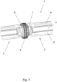
- Figure 1 shows a connection arrangement 1 for producing a fluid-tight connection of a first pipe arrangement 2 with a second pipe arrangement 3.
- the first pipe arrangement 2 and the second pipe arrangement 3 each have 3 channels 4, 5, 13.
- the first pipe arrangement 2 is assigned a first coupling element 6 and the second pipe arrangement 3 is assigned a second coupling element 7, wherein the channels 4, 5, 13 are arranged concentrically in the region of the coupling elements 6, 7.
- the channels 4, 5, 13 run next to each other in a transition region in the region of the coupling elements 6, 7.
- the first coupling element 6 and the second coupling element 7 are connected to one another by a locking element 8, wherein the locking element 8 encompasses the channels 4, 5, 13. Both coupling elements 6, 7 have a cylindrical outer contour 9 for receiving the locking element 8.
- the locking element 8 is designed as a coupling ring.
- connection arrangement 1 is equipped with a device for detecting the connection status.
- optically readable means in the form of a QR code are attached to both coupling elements 6, 7.
- the optical means can be arranged in such a way that they can only be recognized if the connection arrangement 1 has been correctly manufactured.
- the means are initially concealed and are only exposed after connection by being visible through a window made in the locking element 8.
- the means can be read electronically.
- RFID chips are attached to both coupling elements 6, 7, which can only be read if the connection arrangement is correctly established.
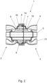
- FIGS. 2 and 3 show the Figure 1 shown connection arrangement 1 in section. It can be seen that a two-part insert 16 is assigned to the coupling elements 6, 7, with the channels 4, 5, 13 running within the insert 16. A first insert element 16' is assigned to the first coupling element 6 and a second insert element 16 is assigned to the second coupling element 7. The two elements of the insert 16 have congruently shaped end faces, with seals 14 being provided which seal the channels 4, 5, 13 against one another.
- the front sides of the insert elements 16, 16' have labyrinth structures, which further reduce the risk of leakage.
- the outer contours 9 are designed to receive the locking element 8 from the insert 16, so that the insert 16 forms the coupling elements 6, 7 in sections.
- the channels 4, 5, 13 run concentrically within the insert 16.
- inlet contours are formed that run obliquely towards the front sides, so that both the insert 16 and the connection arrangement 1 as a whole can be designed to be particularly compact.
- the first pipe arrangement 2 and the second pipe arrangement 3 are designed as blow-molded parts and consist of polymer material.
- the insert 16 and the locking element 8 are designed as injection-molded parts and also consist of polymer material.
- the material is preferably selected from the group of polyamides or polyolefins.
- Figure 4 shows the Figure 1 shown connection arrangement 1 in a partially transparent representation.
- the locking means 15 formed from the locking element 8 can be seen, which prevents the locking element from automatically releasing from the coupling elements 6, 7.
- Figure 5 shows the Figure 1 shown connection arrangement in a partially sectioned view.
- the insert 16 and the design of the insert 16 in the transition area between the channel guide outside the connection arrangement 1 and the channel guide inside the connection arrangement 1 can be seen.
- the channel 4 flows through the outer ring channel of the insert 16, the channel 13 through the middle ring channel and channel 5 through the inner, centrally arranged, circular channel.
- the inlet of the channel 13 into the insert 16 in the direction of the middle ring channel is designed to run diagonally so that the channel 13 can open into the corresponding ring channel parallel to channel 4.
- the entire connection arrangement 1 can be designed to be particularly compact and in particular has only a small longitudinal extension.
- seals 14 which are arranged in the mouth area of the insert 16 and seal the insert 16 against the channels 4, 5, 13 and thereby prevent internal leakage from occurring.
- the seals 14 are preferably made of injection-moldable elastic material, so that the insert 16 can be designed, for example, as a two-component injection-molded part.
- Figure 6 shows a first design of the Figure 1 shown connecting arrangement 1.
- the outer contour 9 of the first coupling element 6 and the second coupling element 7 are assigned locking contours 10. These are designed to engage in locking means 11 of the locking element 8.
- the locking contours 10 and the locking means 11 are designed like a screw.
- rib-like projections are formed from the outer contours 9 of the coupling elements 6, 7, which run obliquely to the front sides of the coupling elements 6, 7.
- the locking contours of the first coupling element 6 and the second coupling element 7 run in an arrow shape towards each other.
- Figure 7 shows a locking element 8 for the Figure 6 shown connecting arrangement 1.
- the locking element 8 has rib-shaped inwardly projecting projections which form locking means 11, wherein the locking means 11 engage in the locking contours 10.
- the locking means 11 are also arranged in an arrow shape. To fix it, the locking element forming a collar ring is pushed onto the connecting arrangement 1 and rotated so that the locking means 11 engage in the locking contours 10 and fix the coupling elements 6, 7 to one another.
- locking means 15, 15' are incorporated in the locking element 8 and in a coupling element 6.
- the locking means 15, 15' comprise a tab which is attached in an articulated manner to the locking element 8 and which, in the form of a locking pawl, engages in recesses 15' which are incorporated in the coupling element 6. To release the arrangement, it is necessary to space the tab of the locking means 15 from the recess 15'.
- the locking means 15, 15' is shown in detail in Figure 8 and shown there in cross-section.
- Figure 9 shows the connection arrangement 1 in the area of the locking element 8 in detail in section.
- Figure 10 shows an alternative embodiment of the connection arrangement 1 according to Figure 1 , the locking contours 10 and the locking means 11 in this embodiment are designed as a bayonet connection.
- projections are formed from the coupling elements 6, 7 and from the locking element 8, which form the locking contours 10 and the locking means 11.
- this embodiment is also provided with locking means 15. These consist of a projection protruding radially inwards from the locking element 8, which engages in a congruent recess 15' made in a coupling element 6.
- Figure 11 shows a locking element 8 for the connection arrangement 1 according to Figure 10 .
- Figure 12 shows the connection arrangement 1 according to Figure 10 in detail in the area of the locking element 8 and the locking means 15.
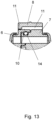
- Figure 13 shows the connection arrangement 1 in detail in section in the area of the locking element 8.
Landscapes
- Engineering & Computer Science (AREA)
- General Engineering & Computer Science (AREA)
- Mechanical Engineering (AREA)
- Manufacturing & Machinery (AREA)
- Chemical & Material Sciences (AREA)
- Chemical Kinetics & Catalysis (AREA)
- Electrochemistry (AREA)
- General Chemical & Material Sciences (AREA)
- Physics & Mathematics (AREA)
- Thermal Sciences (AREA)
- Quick-Acting Or Multi-Walled Pipe Joints (AREA)
Abstract
Description
- Die Erfindung betrifft eine Verbindungsanordnung zur Herstellung einer fluiddichten Verbindung einer ersten Rohranordnung mit einer zweiten Rohranordnung, wobei die erste Rohranordnung und die zweite Rohranordnung jeweils zumindest zwei Kanäle aufweisen.
- Derartige Verbindungsanordnungen werden häufig für den Transport von Temperiermedien in der Elektromobilität eingesetzt. Batterien von Elektrofahrzeugen weisen eine optimale Leistungsfähigkeit nur innerhalb eines begrenzten Temperaturspektrums auf. Daher kann es je nach Umgebungstemperatur erforderlich sein, die Akkumulatoren zu erwärmen oder zu kühlen. Daher weist die Antriebseinheit eines Elektrofahrzeugs in der Regel einen Temperierkreislauf mit einer Rohranordnung auf, durch welchen Temperiermedien zu den Zellen des Akkumulators geleitet werden können, um diese innerhalb eines gewünschten Temperaturspektrums zu temperieren. Aufgrund der Beschränkungen des Bauraums soll die Temperiereinrichtung dabei möglichst kompakt sein.
- Des Weiteren kann es erforderlich sein, Komponenten der gesamten Antriebseinheit von Elektrofahrzeugen zu temperieren, insbesondere zu kühlen. Hierzu gehören neben dem Akkumulator die Leistungselektronik und der Elektromotor. Die Ladelektronik und die dazugehörigen Steckverbindungen und Leitungen können ebenfalls mittels der Temperiereinrichtung gekühlt werden. Dies ist insbesondere im Zusammenhang mit Schnellladevorgängen relevant.
- Neben dem Einsatz in einer Antriebseinheit ergibt sich ein weiteres Einsatzgebiet im Zusammenhang mit der übrigen Fahrzeugelektronik, hier insbesondere von Sensoren und Bordcomputern.
- Temperiermedien kommen ferner in Klimaanlagen zum Einsatz. Klimaanlagen, insbesondere mobile Klimaanlagen, umfassen eine Rohranordnung, welche den Transport von Temperiermedium zwischen den einzelnen Aggregaten der Klimaanlage ermöglicht. Bei mobilen Klimaanlagen, beispielsweise bei Klimaanlagen für die Klimatisierung von Innenräumen von Kraftfahrzeugen, ist die Rohranordnung ein vergleichsweise komplexes Gebilde und umfasst häufig Rohre aus verschiedenen Materialien, beispielsweise Rohre aus Metall, Rohrabschnitte aus thermoplastischem Kunststoff und Rohrabschnitte aus gummiartigem Material. Zwar können hierbei die Einsatzbedingungen der Rohrabschnitte optimal auf die jeweiligen Anforderungen abgestimmt werden, die Rohranordnung ist jedoch kostenintensiv, aufwendig in der Montage und schwierig zu recyclen. Bei der vorliegenden Anordnung kommen vorwiegend wasserbasierte Temperiermedien, beispielsweis Kühlmittel auf Wasser-Glykol-Basis in Betracht.
- In allen Anwendungen besteht zumeist die Anforderung, dass die Rohranordnung besonders kompakt sein soll. Dabei kann es vorkommen, dass mehrere Kanäle einer Rohranordnung einer ersten Einrichtung mit Kanälen einer Rohranordnung einer zweiten Einrichtung verbunden werden müssen, wobei nur sehr wenig Bauraum zur Verfügung steht. Müssen bei beengtem Bauraum mehrere Kanäle miteinander verbunden werden verlängert sich die Montagezeit und es ergeben sich Probleme durch den beengten Bauraum.
- Der Erfindung liegt die Aufgabe zugrunde, eine Verbindungsanordnung bereitzustellen, welche kompakt und einfach zu montieren ist.
- Diese Aufgabe wird mit den Merkmalen von Anspruch 1 gelöst. Auf vorteilhafte Ausgestaltungen nehmen die Unteransprüche Bezug.
- Die erfindungsgemäße Verbindungsanordnung zur Herstellung einer fluiddichten Verbindung weist eine erste Rohranordnung und eine zweite Rohranordnung auf, wobei die erste Rohranordnung und die zweite Rohranordnung jeweils zumindest zwei Kanäle aufweisen, umfassend ein der ersten Rohranordnung zugeordnetes erstes Kupplungselement und ein der zweiten Rohranordnung zugeordnetes zweites Kupplungselement, wobei das erste Kupplungselement und das zweite Kupplungselement durch ein Verriegelungselement miteinander verbindbar sind, wobei das Verriegelungselement die Kanäle umgreift.
- Bei der erfindungsgemäßen Verbindungsanordnung ist dementsprechend lediglich ein einziges Verriegelungselement zum Verbinden der beiden Rohranordnungen vorgesehen. Das Verriegelungselement verriegelt gleichzeitig mehrere Kanäle der Rohranordnungen aneinander. Dabei umgreift das Verriegelungselement die Kanäle und es ergibt sich eine besonders kompakte, bauraumsparende Verbindungsanordnung. Für die Montage der Verbindungsanordnung ist es lediglich erforderlich, das Verriegelungselement zu betätigen und dabei gleichzeitig mehrere Kanäle der beiden Rohranordnungen aneinander zu koppeln. Dadurch verkürzt sich die Montagezeit und Montagefehler, beispielsweise eine unzureichende oder fehlende Verbindung einzelner Kanäle, kann vermieden werden.
- Zumindest ein Kupplungselement kann eine zylinderförmige Außenkontur zur Aufnahme des Verriegelungselementes aufweisen. Vorzugsweise weisen das erste Kupplungselement und das zweite Kupplungselement jeweils eine zylinderförmige Außenkontur zur Aufnahme des Verriegelungselementes auf. Bei dieser Ausgestaltung kann das Verriegelungselement ringförmig ausgebildet sein, sodass dass Verriegelungselement einfach und kostengünstig herstellbar ist. Durch die zylinderförmige Außenkontur kann darüber hinaus das Verriegelungselement drehbar die Kupplungselemente umgreifen, was ein besonders einfaches Arretieren der Kupplungselemente mit dem Verriegelungselement ermöglicht.
- Das Verriegelungselement kann als Überwurfring ausgebildet sein. Dadurch ist das Verriegelungselement besonders einfach und kostengünstig herstellbar. Insbesondere ist es denkbar, das Verriegelungselement aus Kunststoff, beispielsweise aus einem spritzgießfähigen Kunststoff, auszubilden.
- Der Außenkontur von erstem Kupplungselement und/oder zweitem Kupplungselement können Verriegelungskonturen zugeordnet sein, welche eingerichtet sind, in Verriegelungsmitteln des Verriegelungselements einzugreifen. Dadurch kann das Verriegelungselement beide Kupplungselemente fest aneinander fixieren, sodass beide Rohranordnungen verliersicher aneinander festgelegt sind. Dadurch, dass das Verriegelungselement die Kupplungselemente umgreift ist ein besonders einfaches Festlegen möglich.
- Je nach Ausgestaltung der Verbindungsanordnung ist denkbar, dass das Verriegeln der Kupplungselemente durch das Verriegelungselement werkzeuglos erfolgen kann.
- Die Verriegelungskonturen können in Form von Erhebungen und/oder Vertiefungen ausgebildet sein, welche aus der Außenkontur der Kupplungselemente hervorstehen oder in die Außenkontur hineinragen. Die Verriegelungsmittel des Verriegelungselementes sind vorzugsweise kongruent zu den Verriegelungskonturen ausgebildet. Dementsprechend können die am Innenumfang des Verriegelungselementes angeordneten Verriegelungsmittel über die Oberfläche nach innen hervorstehen oder alternativ in Form von Vertiefungen ausgebildet sein. Vorzugsweise stehen die Verriegelungskonturen der Kupplungselemente nach außen vor und die Verriegelungsmittel des Verriegelungselementes ragen nach innen aus der inneren Umfangsfläche hervor.
- Gemäß einer ersten Ausgestaltung können die Verriegelungskonturen und die Verriegelungsmittel schraubenartig ausgebildet sein. Hierzu können die Verriegelungskonturen und die Verriegelungsmittel abschnittsweise schraubengangförmig ausgebildet sein und beispielsweise in Form von schräg verlaufenden Rippen ausgebildet sein, welche aus den Oberflächen von Kupplungselementen und Verriegelungselement hervorstehen. Die Fixierung der Kupplungselemente und des Verriegelungselementes erfolgt dann durch eine Schraubbewegung des Verriegelungselementes relativ zu den Kupplungselementen.
- Um zu verhindern, dass sich das Verriegelungselement ungewollt von den Kupplungselementen löst, können Rastmittel vorgesehen sein, welche das Verriegelungselement auf den Kupplungselementen fixieren. Die Rastelemente können beispielsweise in Form einer Sperrklinke ausgebildet sein. Die Sperrklinke kann eine aus dem Verriegelungselement ausgebildete bewegliche Lasche und eine in zumindest in ein Kupplungselement eingebrachte Vertiefung umfassen. Die Lasche greift dabei nach Art einer Sperrklinke in die Vertiefungen ein und blockiert eine Drehbewegung des Verriegelungselementes in der Öffnungsrichtung. Zum Lösen der Verbindung ist es erforderlich, die Lasche aus der Vertiefung zu beabstanden.
- Die Verriegelungskonturen und die Verriegelungsmittel können als Bajonettverbindung ausgebildet sein. Eine Bajonettverbindung ist besonders einfach zu fügen und verfügt über einen definierten Winkelbereich, innerhalb dessen die Verbindung zwischen Verriegelungselement und Kupplungselementen geschlossen, bzw. geöffnet werden kann. Um zu verhindern, dass sich die Verbindung selbsttätig löst können Rastmittel vorgesehen sein. Beispielsweise ist es denkbar, dass aus dem Verriegelungsmittel ein oder mehrere radial nach innen ragende Vorsprünge ausgebildet sind, welche in zumindest in ein Kupplungselement eingebrachte kongruente Vertiefungen eingreifen. Sobald die Rastmittel ineinander greifen wird durch den Rastvorgang gleichzeitig signalisiert, dass die Verbindung zwischen Verbindungselement und Kupplungselementen vollständig hergestellt ist. Dadurch vereinfacht sich die Montage.
- Die Verbindungsanordnung kann mit einer Einrichtung zum Erkennen des Verbindungsstatus ausgerüstet sein. Ein derartiges Einrichtung vereinfacht die Qualitätskontrolle, weil mit einfachen Mitteln erkannt werden kann, wenn die Komponenten der Verbindungsanordnung fest und dicht miteinander verbunden sind. Die Einrichtung kann dabei optische und/oder elektronische Mittel aufweisen.
- Die optischen Mittel können derart ausgerüstet und angeordnet sein, dass diese nur erkennbar sind, wenn die Verbindungsanordnung korrekt verbunden ist. Hierzu kann an einem oder beiden Kupplungselementen ein optisch auslesbarer Code angebracht, welcher verdeckt ist und erst nach dem Verbinden freiliegt. Dies kann durch ein in das Verriegelungselement eingebrachtes Fenster realisiert sein. Der optische Code kann ein QR-Code oder ein Barcode sein, so dass der Code zusätzlich Produktinformationen tragen kann. Denkbar sind auch Farbcodierungen.
- Die elektronischen Mittel können so ausgerüstet sein, dass diese nur auslesbar sind, wenn die Verbindungsanordnung korrekt verbunden ist. Hierzu kann ein einem oder beiden Kupplungselementen ein Transponder angeordnet sein, der zunächst abgeschirmt ist und erst nach dem Verbinden auslesbar ist. Denkbar ist auch eine Zustandsänderung des Transponders nach dem Verbinden. Die elektronischen Mittel können als RFID-Chip ausgebildet sein.
- Gemäß einer ersten Ausgestaltung können die Kanäle in zumindest einem Kupplungselement abschnittsweise konzentrisch angeordnet sein. Bei dieser Ausgestaltung sind die Kanäle ineinander geschachtelt, wobei ein Kanal mittig durch die Verbindungsanordnung hindurchlaufen kann und andere Kanäle den mittig angeordneten Kanal umfangsseitig, beispielsweise in Form von Ringkanälen, umgeben. Dadurch ergibt sich eine besonders kompakte Verbindungsanordnung.
- Gemäß einer alternativen Ausgestaltung ist aus den Kupplungselementen ein Übergangsbereich ausgebildet, in welchem die Kanäle nebeneinander verlaufen. Beispielsweise ist denkbar, dass die Kanäle tortenstückartig in dem Übergangsbereich verlaufen. Bei dieser Ausgestaltung können Leckagen besonders einfach vermieden werden.
- Bei beiden Ausgestaltungen ist denkbar, das Kanäle im Bereich der Verbindungsanordnung ineinander münden, beispielsweise ist denkbar, dass im Bereich der Verbindungsanordnung zwei von drei Kanälen zusammengeführt werden.
- Es kann zumindest ein Einsatz vorgesehen sein, durch welchen im Bereich der Kupplungselemente die Kanäle verlaufen. Dadurch ist es möglich, die Rohranordnungen im Bereich der Kupplungselemente besonders einfach und kostengünstig auszugestalten. Dabei ist insbesondere denkbar, dass der Einsatz einen Bestandteil der Kupplungselemente bildet, wobei insbesondere die Außenkontur mit den Verriegelungskonturen aus dem Einsatz ausgebildet sein kann. Dabei kann der Einsatz mehrteilig, insbesondere zweiteilig ausgebildet sein, wobei jeder Rohranordnung ein Einsatzteil zugeordnet ist. Die dichtende Verbindung zwischen den Rohranordnungen erfolgt in diesem Fall über die Einsatzteile des Einsatzes. Die im Bereich der Kupplungselemente komplex geformten Kanäle sind innerhalb des Einsatzes ausgeformt. Der Einsatz ist vorzugsweise ein Kunststoffbauteil und besteht vorzugsweise aus spritzgießfähigem Kunststoff.
- Die erste Rohranordnung und/oder die zweite Rohranordnung können zumindest drei Kanäle aufweisen. Die Ausgestaltung von mehr als zwei Kanälen ermöglicht eine komplexe Rohrleitungsstruktur und insgesamt eine kompakte Anordnung.
- Den Kupplungselementen können Dichtungen zugeordnet sein, welche die Kanäle gegeneinander abdichten. Dadurch kann die Gefahr innerer Leckagen reduziert werden.
- Die erste Rohranordnung und/oder die zweite Rohranordnung können als Blasformteil ausgebildet sein. Dementsprechend sind die erste Rohranordnung und die zweite Rohranordnung vorzugsweise aus polymerem Material ausgebildet. Durch das Blasformen ist es möglich, einteilige Rohranordnungen mit komplexer Gestalt kostengünstig herzustellen.
- Ein erfindungsgemäßer Temperierkreislauf zum Transport von Temperiermedium umfasst zumindest eine erfindungsgemäße Verbindungsanordnung. Der Temperierkreislauf eignet sich dabei insbesondere zum Temperieren von Komponenten eines Elektrofahrzeugs, wobei durch die Kanäle Temperiermedium, beispielsweise Wasser, zum Erhitzen oder zum Kühlen von Komponenten des Fahrzeugs geleitet werden kann. Durch die besonders kompakte Ausgestaltung der Verbindungsanordnung und die Ausbildung der Komponenten der Verbindungsanordnung aus Kunststoff ist die Herstellung eines besonders leichten und kompakten Temperierkeislaufs möglich.
- Einige Ausgestaltungen der erfindungsgemäßen Verbindungsanordnung werden nachfolgend anhand der Figuren näher erläutert. Diese zeigen, jeweils schematisch:
- Fig. 1
- eine Verbindungsanordnung in dreidimensionaler Darstellung;
- Fig. 2
- die Verbindungsanordnung gemäß
Fig. 1 im Schnitt; - Fig. 3
- die Verbindungsanordnung gemäß
Fig. 1 im Schnitt; - Fig. 4
- die Verbindungsanordnung gemäß
Fig. 1 in teiltransparenter Darstellung; - Fig. 5
- die Verbindungsanordnung gemäß
Fig. 1 in teilgeschnittener Darstellung; - Fig. 6
- die Verbindungsanordnung mit schraubenförmigen Verriegelungsmitteln;
- Fig. 7
- ein Verriegelungselement für die Verbindungsanordnung gemäß
Fig. 6 ; - Fig. 8
- im Detail das Rastmittel der Verbindungsanordnung gemäß
Fig. 6 ; - Fig. 7
- im Detail die Verbindungsanordnung gemäß
Fig. 6 im Bereich des Verriegelungselementes im Schnitt; - Fig. 10
- eine Verbindungsanordnung mit einer Bajonettverbindung;
- Fig. 11
- ein Verriegelungselement für die Verbindungsanordnung gemäß
Fig. 10 ; - Fig. 12
- im Detail ein Rastmittel dem Verbindungsanordnung gemäß
Fig. 10 ; - Fig. 13
- im Detail die Verbindungsanordnung gemäß
Fig. 10 im Bereich des Verriegelungselementes im Schnitt. - Die Figuren zeigen eine Verbindungsanordnung 1, wobei die Verbindungsanordnung 1 einen Bestandteil eines Temperierkreislaufs zum Transport von Temperiermedium bildet. Konkret ist die Verbindungsanordnung 1 in einen Temperierkreislauf eines elektromotorischen Antriebes eines Elektrofahrzeuges eingebunden und leitet Volumenströme des in den Temperierkreislauf geführten Mediums zu den elektrischen Energiespeichern und Elektromotoren sowie zur Leistungselektronik.
-
Figur 1 zeigt eine Verbindungsanordnung 1 zur Herstellung einer fluiddichten Verbindung einer ersten Rohranordnung 2 mit einer zweiten Rohranordnung 3. Die erste Rohranordnung 2 und die zweite Rohranordnung 3 weisen jeweils 3 Kanäle 4, 5, 13 auf. Der ersten Rohranordnung 2 ist ein erstes Kupplungselement 6 und der zweiten Rohranordnung 3 ist ein zweites Kupplungselement 7 zugeordnet, wobei die Kanäle 4, 5, 13 im Bereich der Kupplungselemente 6, 7 konzentrisch angeordnet sind. - Gemäß einer alternativen Ausgestaltung verlaufen die Kanäle 4, 5, 13 im Bereich der Kupplungselemente 6, 7 in einem Übergangsbereich nebeneinander.
- Das erste Kupplungselement 6 und das zweite Kupplungselement 7 sind durch ein Verriegelungselement 8 miteinander verbunden, wobei das Verriegelungselement 8 die Kanäle 4, 5, 13 umgreift. Beide Kupplungselemente 6, 7 weisen eine zylinderförmige Außenkontur 9 zur Aufnahme des Verriegelungselementes 8 auf. Das Verriegelungselement 8 ist als Überwurfring ausgebildet.
- Die Verbindungsanordnung 1 ist mit einer Einrichtung zum Erkennen des Verbindungsstatus ausgerüstet. Hierzu sind an beiden Kupplungselementen 6, 7 optisch auslesbare Mitteln in Form eines QR-Codes angebracht. Dabei sind die optischen Mittel können derart angeordnet sein, dass diese nur erkennbar sind, wenn die Verbindungsanordnung 1 korrekt hergestellt ist. Dazu sind die Mittel zunächst verdeckt und liegen erst nach dem Verbinden frei, indem diese ein in das Verriegelungselement 8 eingebrachtes Fenster erkennbar sind.
- Gemäß einer alternativen Ausgestaltung sind die Mittel elektronisch auslesbar. Dazu sind an beiden Kupplungselementen 6, 7 RFID-Chips angebracht, welche nur auslesbar sind, wenn die Verbindungsanordnung korrekt hergestellt ist.
- Die
Figuren 2 und3 zeigen die inFigur 1 gezeigte Verbindungsanordnung 1 im Schnitt. Dabei ist zu erkennen, dass ein zweiteilig ausgebildeter Einsatz 16 den Kupplungselementen 6, 7 zugeordnet ist, wobei die Kanäle 4, 5, 13 innerhalb des Einsatzes 16 verlaufen. Ein erstes Einsatzelement 16' ist dem ersten Kupplungselement 6 und ein zweites Einsatzelement 16 ist dem zweiten Kupplungselement 7 zugeordnet. Die beiden Elemente des Einsatzes 16 weisen kongruent geformte Stirnflächen auf, wobei Dichtungen 14 vorgesehen sind, welche die Kanäle 4, 5, 13 gegeneinander abdichten. - Des Weiteren weisen die Stirnseiten der Einsatzelemente 16, 16' Labyrinthstrukturen auf, welche die Leckagegefahr weiter reduzieren. Bei der hier gezeigten
- Ausgestaltung sind die Außenkonturen 9 zur Aufnahme des Verriegelungselementes 8 aus dem Einsatz 16 ausgebildet, so dass der Einsatz 16 abschnittsweise die Kupplungselemente 6, 7 ausbildet.
- Innerhalb des Einsatzes 16 verlaufen die Kanäle 4, 5, 13 konzentrisch. Im Übergangsbereich zu den in den Rohranordnungen 2, 3 verlaufenden Kanälen 4, 5, 13 sind zu den Stirnseiten schräg verlaufende Einlaufkonturen ausgebildet, sodass sowohl der Einsatz 16 als auch die Verbindungsanordnung 1 insgesamt besonders kompakt ausgebildet sein kann.
- Die erste Rohranordnung 2 und die zweite Rohranordnung 3 sind als Blasformteil ausgebildet und bestehen aus polymerem Werkstoff. Der Einsatz 16 und das Verriegelungselement 8 sind als Spritzgießteile ausgebildet und bestehen ebenfalls aus polymerem Werkstoff. Der Werkstoff ist vorzugsweise aus der Gruppe der Polyamide oder Polyolefine ausgewählt.
-
Figur 4 zeigt die inFigur 1 gezeigte Verbindungsanordnung 1 in teiltransparenter Darstellung. Zu erkennen ist insbesondere das aus dem Verriegelungselement 8 ausgebildete Rastmittel 15, welches ein selbsttätiges Lösen des Verriegelungselementes von den Kupplungselementen 6, 7 verhindert. -
Figur 5 zeigt die inFigur 1 gezeigte Verbindungsanordnung in teilgeschnittener Darstellung. Zu erkennen ist insbesondere der Einsatz 16 und die Ausgestaltung des Einsatzes 16 im Übergangsbereich zwischen der Kanalführung außerhalb der Verbindungsanordnung 1 und der Kanalführung innerhalb der Verbindungsanordnung 1. Zu erkennen ist, dass der Kanal 4 den äußeren Ringkanal des Einsatzes 16 durchströmt, der Kanal 13 den mittleren Ringkanal und Kanal 5 den inneren, zentrisch angeordneten, kreisförmigen Kanal. Der Einlauf des Kanals 13 in den Einsatz 16 in Richtung des mittleren Ringkanals ist schrägverlaufend ausgebildet, sodass der Kanal 13 parallel zu Kanal 4 in den entsprechenden Ringkanal münden kann. Dadurch kann die gesamte Verbindungsanordnung 1 besonders kompakt ausgebildet sein und weist insbesondere nur eine geringe Längserstreckung auf. - Zu erkennen sind ferner Dichtungen 14 die im Mündungsbereich des Einsatzes 16 angeordnet sind und den Einsatz 16 gegenüber den Kanälen 4, 5, 13 abdichten und dadurch verhindern, dass eine innere Leckage auftritt. Die Dichtungen 14 sind vorzugsweise aus spritzgießfähigem elastischem Material ausgebildet, sodass der Einsatz 16 beispielsweise als Zweikomponentenspritzgießteil ausgebildet sein kann.
-
Figur 6 zeigt eine erste Ausgestaltung der inFigur 1 gezeigten Verbindungsanordnung 1. Der Außenkontur 9 des ersten Kupplungselementes 6 und des zweiten Kupplungselementes 7 sind Verriegelungskonturen 10 zugeordnet. Diese sind eingerichtet, in Verriegelungsmittel 11 des Verriegelungselementes 8 einzugreifen. Bei der Ausgestaltung gemäßFigur 6 sind die Verriegelungskonturen 10 und die Verriegelungsmittel 11 schraubenartig ausgebildet. Hierzu sind aus den Außenkonturen 9 der Kupplungselemente 6, 7 rippenartige Vorsprünge ausgebildet, die zu den Stirnseiten der Kupplungselemente 6, 7 schräg verlaufen. Bei der vorliegenden Ausgestaltung verlaufen die Verriegelungskonturen von erstem Kupplungselement 6 und zweitem Kupplungselement 7 pfeilförmig zueinander. -
Figur 7 zeigt ein Verriegelungselement 8 für die inFigur 6 gezeigte Verbindungsanordnung 1. Dabei ist zu erkennen, dass das Verriegelungselement 8 rippenförmige nach innen ragende Vorsprünge aufweist, welche Verriegelungsmittel 11 bilden, wobei die Verriegelungsmittel 11 in die Verriegelungskonturen 10 eingreifen. Die Verriegelungsmittel 11 sind ebenfalls pfeilförmig angeordnet. Zum Fixieren wird das einen Überwurfring bildende Verriegelungselement auf die Verbindungsanordnung 1 aufgeschoben und so verdreht, dass die Verriegelungsmittel 11 in die Verriegelungskonturen 10 eingreifen und die Kupplungselemente 6, 7 aneinander fixieren. - Um zu verhindern, dass sich das Verriegelungselement 8 selbsttätig löst sind in das Verriegelungselement 8 und in ein Kupplungselement 6 Rastmittel 15, 15' eingebracht. Die Rastmittel 15, 15' umfassen eine gelenkig an den Verriegelungselement 8 angebrachte Lasche auf, welche in Form einer Sperrklinke in Vertiefungen 15' eingreift, die in das Kupplungselement 6 eingebracht sind. Zum Lösen der Anordnung ist es erforderlich, die Lasche des Rastmittels 15 von der Vertiefung 15' zu beabstanden.
- Das Rastmittel 15, 15' ist im Detail in
Figur 8 gezeigt und dort im Schnitt dargestellt. -
Figur 9 zeigt die Verbindungsanordnung 1 im Bereich des Verriegelungselementes 8 im Detail im Schnitt. -
Figur 10 zeigt eine alternative Ausgestaltung der Verbindungsanordnung 1 gemäßFigur 1 , wobei die Verriegelungskonturen 10 und die Verriegelungsmittel 11 bei dieser Ausgestaltung als Bajonettverbindung ausgebildet sind. Hierzu sind aus den Kupplungselementen 6, 7 und aus dem Verriegelungselement 8 Vorsprünge ausgebildet, welche die Verriegelungskonturen 10 und die Verriegelungsmittel 11 ausbilden. Um zu verhindern, dass sich die Verbindung selbsttätig löst ist auch diese Ausgestaltung mit Rastmitteln 15 versehen. Diese bestehen aus einem aus dem Verriegelungselement 8 radial nach innen vorstehenden Vorsprung ausgebildet, welche in eine in ein Kupplungselement 6 eingebrachte kongruente Vertiefung 15' eingreift. -
Figur 11 zeigt ein Verriegelungselement 8 für die Verbindungsanordnung 1 gemäßFigur 10 . -
Figur 12 zeigt die Verbindungsanordnung 1 gemäßFigur 10 im Detail im Bereich des Verriegelungselementes 8 und des Rastmittels 15. -
Figur 13 zeigt die Verbindungsanordnung 1 im Detail im Schnitt im Bereich des Verriegelungselementes 8.
Claims (14)
- Verbindungsanordnung (1) zur Herstellung einer fluiddichten Verbindung einer ersten Rohranordnung (2) mit einer zweiten Rohranordnung (3), wobei die erste Rohranordnung (2) und die zweite Rohranordnung (3) jeweils mindestens zwei Kanäle (4, 5) aufweisen, umfassend ein der ersten Rohranordnung (2) zugeordnetes erstes Kupplungselement (6) und ein der zweiten Rohranordnung (3) zugeordnetes zweites Kupplungselement (7), dadurch gekennzeichnet, dass das erste Kupplungselement (6) und das zweite Kupplungselement (7) durch ein Verriegelungselement (8) miteinander verbindbar sind, wobei das Verriegelungselement (8) die Kanäle (4, 5) umgreift.
- Verbindungsanordnung nach Anspruch 1, dadurch gekennzeichnet, dass zumindest ein Kupplungselement (6, 7) eine zylinderförmige Außenkontur (9) zur Aufnahme des Verriegelungselementes (8) aufweist.
- Verbindungsanordnung nach Anspruch 1 oder 2, dadurch gekennzeichnet, dass das Verriegelungselement (8) als Überwurfring ausgebildet ist.
- Verbindungsanordnung nach einem der Ansprüche 1 bis 3, dadurch gekennzeichnet, dass der Außenkontur (9) von erstem Kupplungselement (6) und/oder zweitem Kupplungselement (7) Verriegelungskonturen (10) zugeordnet sind, welche eingerichtet sind, in Verriegelungsmittel (11) des Verriegelungselementes (8) einzugreifen.
- Verbindungsanordnung nach Anspruch 4, dadurch gekennzeichnet, dass die Verriegelungskonturen (10) und die Verriegelungsmittel (11) schraubenartig ausgebildet sind.
- Verbindungsanordnung nach Anspruch 4, dadurch gekennzeichnet, dass die Verriegelungskonturen (10) und die Verriegelungsmittel (11) als Bajonettverbindung ausgebildet sind.
- Verbindungsanordnung nach einem der Ansprüche 1 bis 6, dadurch gekennzeichnet, dass die Kanäle (4, 5) in zumindest einem Kupplungselement (6, 7) abschnittsweise konzentrisch angeordnet sind.
- Verbindungsanordnung nach einem der Ansprüche 1 bis 6, dadurch gekennzeichnet, dass aus den Kupplungselementen (6, 7) ein Übergangsbereich ausgebildet ist, in welchem die Kanäle (4, 5) nebeneinander verlaufen.
- Verbindungsanordnung nach einem der Ansprüche 1 bis 8, dadurch gekennzeichnet, dass zumindest ein Einsatz (16) vorgesehen ist, durch welchen im Bereich der Kupplungselemente (6, 7) die Kanäle (4, 5) verlaufen.
- Verbindungsanordnung nach einem der Ansprüche 1 bis 9, dadurch gekennzeichnet, dass die erste Rohranordnung (2) und/oder die zweite Rohranordnung (3) zumindest drei Kanäle (4, 5, 13) aufweisen.
- Verbindungsanordnung nach einem der Ansprüche 1 bis 10, dadurch gekennzeichnet, dass den Kupplungselementen (6, 7) Dichtungen (14) zugeordnet sind, welche die Kanäle (4, 5, 13) gegeneinander abdichten.
- Verbindungsanordnung nach einem der Ansprüche 1 bis 11, dadurch gekennzeichnet, dass die erste Rohranordnung (2) und/oder die zweite Rohranordnung (3) als Blasformteil ausgebildet sind.
- Verbindungsanordnung nach einem der Ansprüche 1 bis 12, dadurch gekennzeichnet, dass die erste Rohranordnung (2), die zweite Rohranordnung (3), das erste Kupplungselement (6), das zweite Kupplungselement (7) und/oder das Verriegelungselement (8) aus polymerem Werkstoff ausgebildet sind.
- Temperierkreislauf zum Transport von Temperiermedium, umfassend zumindest eine Verbindungsanordnung (1) nach einem der vorherigen Ansprüche.
Priority Applications (5)
| Application Number | Priority Date | Filing Date | Title |
|---|---|---|---|
| EP22208887.4A EP4375552A1 (de) | 2022-11-22 | 2022-11-22 | Verbindungsanordnung |
| US18/389,098 US20240167605A1 (en) | 2022-11-22 | 2023-11-13 | Connection arrangement |
| KR1020230159726A KR20240076716A (ko) | 2022-11-22 | 2023-11-17 | 연결 장치 |
| CN202311557192.1A CN118066398A (zh) | 2022-11-22 | 2023-11-21 | 连接装置 |
| JP2023197168A JP2024075513A (ja) | 2022-11-22 | 2023-11-21 | 接続アセンブリ |
Applications Claiming Priority (1)
| Application Number | Priority Date | Filing Date | Title |
|---|---|---|---|
| EP22208887.4A EP4375552A1 (de) | 2022-11-22 | 2022-11-22 | Verbindungsanordnung |
Publications (1)
| Publication Number | Publication Date |
|---|---|
| EP4375552A1 true EP4375552A1 (de) | 2024-05-29 |
Family
ID=84361253
Family Applications (1)
| Application Number | Title | Priority Date | Filing Date |
|---|---|---|---|
| EP22208887.4A Pending EP4375552A1 (de) | 2022-11-22 | 2022-11-22 | Verbindungsanordnung |
Country Status (5)
| Country | Link |
|---|---|
| US (1) | US20240167605A1 (de) |
| EP (1) | EP4375552A1 (de) |
| JP (1) | JP2024075513A (de) |
| KR (1) | KR20240076716A (de) |
| CN (1) | CN118066398A (de) |
Citations (4)
| Publication number | Priority date | Publication date | Assignee | Title |
|---|---|---|---|---|
| FR1479524A (fr) * | 1966-03-24 | 1967-05-05 | Citroen Sa Andre | Raccord multiple pour canalisations de fluide |
| US20100318069A1 (en) * | 2007-12-20 | 2010-12-16 | Smith & Nephew Plc | Multi-channel coupling for multi-lumen tube |
| US20120217739A1 (en) * | 2009-11-12 | 2012-08-30 | Karl Weinhold | Apparatus for connecting double jacketed pipes |
| EP3964374A1 (de) * | 2020-09-03 | 2022-03-09 | TI Automotive Technology Center GmbH | Rohranordnung für den transport von temperiermedien |
Family Cites Families (10)
| Publication number | Priority date | Publication date | Assignee | Title |
|---|---|---|---|---|
| US3818939A (en) * | 1972-08-24 | 1974-06-25 | Aeroquip Corp | Petroleum transfer self-sealing coupling |
| US4142742A (en) * | 1977-09-15 | 1979-03-06 | Cornett Gerald W | Swivel fitting for flexible conduits |
| US6851724B2 (en) * | 2002-06-20 | 2005-02-08 | Raytheon Company | Dual flow rotating union |
| DE102009030936A1 (de) * | 2009-06-23 | 2010-12-30 | Eisele Pneumatics Gmbh & Co. Kg | Vorrichtung zum Verbinden von zwei Leitungsabschnitten, insbesondere eine Mehrfachkupplung mit einem integrierten Absperrventil |
| GB2505132A (en) * | 2011-06-08 | 2014-02-19 | Nxstage Medical Inc | Methods, devices, and systems for coupling fluid lines |
| EP2830699B1 (de) * | 2012-03-27 | 2021-08-18 | Cytiva Sweden AB | Aseptisches verbindungselement |
| EP3332938B1 (de) * | 2012-07-02 | 2020-04-22 | Norma U.S. Holding LLC | Kraftstoffleitungsverbinder, verfahren zur herstellung |
| WO2018144372A1 (en) * | 2017-02-01 | 2018-08-09 | Parker-Hannifin Corporation | Sub-sea connector |
| EP4008935A1 (de) * | 2020-12-03 | 2022-06-08 | TI Automotive Technology Center GmbH | Rotationsventil |
| CN215129978U (zh) * | 2021-04-16 | 2021-12-14 | 上海导向医疗系统有限公司 | 一种高压低温条件下的密封连接装置及冷冻治疗系统 |
-
2022
- 2022-11-22 EP EP22208887.4A patent/EP4375552A1/de active Pending
-
2023
- 2023-11-13 US US18/389,098 patent/US20240167605A1/en not_active Abandoned
- 2023-11-17 KR KR1020230159726A patent/KR20240076716A/ko not_active Ceased
- 2023-11-21 JP JP2023197168A patent/JP2024075513A/ja active Pending
- 2023-11-21 CN CN202311557192.1A patent/CN118066398A/zh active Pending
Patent Citations (4)
| Publication number | Priority date | Publication date | Assignee | Title |
|---|---|---|---|---|
| FR1479524A (fr) * | 1966-03-24 | 1967-05-05 | Citroen Sa Andre | Raccord multiple pour canalisations de fluide |
| US20100318069A1 (en) * | 2007-12-20 | 2010-12-16 | Smith & Nephew Plc | Multi-channel coupling for multi-lumen tube |
| US20120217739A1 (en) * | 2009-11-12 | 2012-08-30 | Karl Weinhold | Apparatus for connecting double jacketed pipes |
| EP3964374A1 (de) * | 2020-09-03 | 2022-03-09 | TI Automotive Technology Center GmbH | Rohranordnung für den transport von temperiermedien |
Also Published As
| Publication number | Publication date |
|---|---|
| CN118066398A (zh) | 2024-05-24 |
| JP2024075513A (ja) | 2024-06-03 |
| KR20240076716A (ko) | 2024-05-30 |
| US20240167605A1 (en) | 2024-05-23 |
Similar Documents
| Publication | Publication Date | Title |
|---|---|---|
| EP2957809B1 (de) | Kupplungselement zur flexiblen verbindung zweier elemente zur führung von medien | |
| EP1445529B1 (de) | Verbindungsanordnung für Kältemittelleitungen | |
| EP2405169A1 (de) | Bauteil für einen Befestigungsclip und Befestigungsclip | |
| EP2220510B1 (de) | Verfahren zur herstellung eines magnetfeldsensors und nach dem verfahren hergestellter sensor | |
| EP3919299B1 (de) | Rohranordnung für den transport von temperiermedium | |
| DE102017207911A1 (de) | Batteriemodulgehäuse, Verfahren zur Herstellung eines solchen und Batteriemodul | |
| EP2602530A2 (de) | Gliederschlauch, gelenkige Verbindung | |
| EP4067048B1 (de) | Verfahren zur herstellung einer anordnung für den transport von medien und anordnung | |
| EP3964374B1 (de) | Rohranordnung für den transport von temperiermedien | |
| DE102022115697A1 (de) | Ventilgehäuse mit Dichtungsaufnahmetaschen eines KFZ-Wegeventils zum Einstellen einer Fluidströmung | |
| EP1608994A1 (de) | Sensoranordnung einer einparkhilfe | |
| DE102013000628A1 (de) | Halterahmen einer Frischluftklappe eines Kraftfahrzeuges sowie Frischluftklappe mit Halterahmen | |
| DE102018124053B4 (de) | Hochvolt (HV)-Batterie mit einer Kühleinrichtung zum Kühlen elektrischer Module derselben | |
| DE102019134649A1 (de) | Batterie für ein Kraftfahrzeug | |
| EP1496301B1 (de) | Steckverbindung | |
| WO2015149772A1 (de) | Haltevorrichtung | |
| EP3009722B1 (de) | Thermostatventil | |
| DE102015205553A1 (de) | Behälter einer Klimaanlage | |
| DE102022131180B3 (de) | Batterie für ein Elektrofahrzeug | |
| DE102007042841A1 (de) | Anschlussvorrichtung | |
| EP4067667B1 (de) | Anordnung für den transport von medien und verfahren zu deren herstellung | |
| DE102007042868A1 (de) | Brennkraftmaschine mit einem Wärmetauscher und ein zur Anwendung bei der Brennkraftmaschine bestimmter Wärmetauscher | |
| DE102018106492A1 (de) | Klimaanlagengehäuse | |
| DE102017216519A1 (de) | Wärmeübertragungselement, Temperiervorrichtung und Batteriegehäuse mit mindestens einem Wärmeübertragungselement | |
| DE102019105984B3 (de) | Dichtring zur Verbindung von zwei fluidführenden Elementen, Kühlsystem mit einem solchen Dichtring für eine Traktionsbatterie eines elektrisch betriebenen Fahrzeugs und Verfahren zum Herstellen eines solchen Kühlsystems |
Legal Events
| Date | Code | Title | Description |
|---|---|---|---|
| PUAI | Public reference made under article 153(3) epc to a published international application that has entered the european phase |
Free format text: ORIGINAL CODE: 0009012 |
|
| STAA | Information on the status of an ep patent application or granted ep patent |
Free format text: STATUS: THE APPLICATION HAS BEEN PUBLISHED |
|
| AK | Designated contracting states |
Kind code of ref document: A1 Designated state(s): AL AT BE BG CH CY CZ DE DK EE ES FI FR GB GR HR HU IE IS IT LI LT LU LV MC ME MK MT NL NO PL PT RO RS SE SI SK SM TR |
|
| STAA | Information on the status of an ep patent application or granted ep patent |
Free format text: STATUS: REQUEST FOR EXAMINATION WAS MADE |
|
| 17P | Request for examination filed |
Effective date: 20241108 |
|
| RBV | Designated contracting states (corrected) |
Designated state(s): AL AT BE BG CH CY CZ DE DK EE ES FI FR GB GR HR HU IE IS IT LI LT LU LV MC ME MK MT NL NO PL PT RO RS SE SI SK SM TR |
|
| STAA | Information on the status of an ep patent application or granted ep patent |
Free format text: STATUS: EXAMINATION IS IN PROGRESS |
|
| 17Q | First examination report despatched |
Effective date: 20250826 |
|
| STAA | Information on the status of an ep patent application or granted ep patent |
Free format text: STATUS: THE APPLICATION IS DEEMED TO BE WITHDRAWN |