EP4375342A1 - Ink composition, organic material layer comprising same, and organic light-emitting device comprising same - Google Patents
Ink composition, organic material layer comprising same, and organic light-emitting device comprising same Download PDFInfo
- Publication number
- EP4375342A1 EP4375342A1 EP22870266.8A EP22870266A EP4375342A1 EP 4375342 A1 EP4375342 A1 EP 4375342A1 EP 22870266 A EP22870266 A EP 22870266A EP 4375342 A1 EP4375342 A1 EP 4375342A1
- Authority
- EP
- European Patent Office
- Prior art keywords
- group
- substituted
- unsubstituted
- layer
- ink composition
- Prior art date
- Legal status (The legal status is an assumption and is not a legal conclusion. Google has not performed a legal analysis and makes no representation as to the accuracy of the status listed.)
- Pending
Links
- 239000000203 mixture Substances 0.000 title claims abstract description 162
- 239000011368 organic material Substances 0.000 title claims abstract description 136
- 238000002347 injection Methods 0.000 claims description 150
- 239000007924 injection Substances 0.000 claims description 150
- 239000000126 substance Substances 0.000 claims description 110
- 125000004432 carbon atom Chemical group C* 0.000 claims description 100
- 239000002904 solvent Substances 0.000 claims description 93
- 125000000217 alkyl group Chemical group 0.000 claims description 75
- 125000003118 aryl group Chemical group 0.000 claims description 67
- 230000005525 hole transport Effects 0.000 claims description 61
- 150000001875 compounds Chemical class 0.000 claims description 58
- 230000000903 blocking effect Effects 0.000 claims description 50
- 125000001424 substituent group Chemical group 0.000 claims description 48
- 229910052739 hydrogen Inorganic materials 0.000 claims description 43
- 239000001257 hydrogen Substances 0.000 claims description 43
- UFHFLCQGNIYNRP-UHFFFAOYSA-N Hydrogen Chemical compound [H][H] UFHFLCQGNIYNRP-UHFFFAOYSA-N 0.000 claims description 42
- YZCKVEUIGOORGS-OUBTZVSYSA-N Deuterium Chemical compound [2H] YZCKVEUIGOORGS-OUBTZVSYSA-N 0.000 claims description 41
- 229910052805 deuterium Inorganic materials 0.000 claims description 41
- 125000003545 alkoxy group Chemical group 0.000 claims description 31
- 150000008040 ionic compounds Chemical class 0.000 claims description 28
- 125000001072 heteroaryl group Chemical group 0.000 claims description 23
- WYURNTSHIVDZCO-UHFFFAOYSA-N Tetrahydrofuran Chemical compound C1CCOC1 WYURNTSHIVDZCO-UHFFFAOYSA-N 0.000 claims description 20
- 125000005843 halogen group Chemical group 0.000 claims description 20
- 125000002091 cationic group Chemical group 0.000 claims description 16
- 125000000129 anionic group Chemical group 0.000 claims description 14
- 125000000623 heterocyclic group Chemical group 0.000 claims description 13
- 125000003277 amino group Chemical group 0.000 claims description 12
- 125000000753 cycloalkyl group Chemical group 0.000 claims description 12
- CXWXQJXEFPUFDZ-UHFFFAOYSA-N tetralin Chemical compound C1=CC=C2CCCCC2=C1 CXWXQJXEFPUFDZ-UHFFFAOYSA-N 0.000 claims description 12
- 125000000732 arylene group Chemical group 0.000 claims description 11
- YLQBMQCUIZJEEH-UHFFFAOYSA-N tetrahydrofuran Natural products C=1C=COC=1 YLQBMQCUIZJEEH-UHFFFAOYSA-N 0.000 claims description 10
- 125000002947 alkylene group Chemical group 0.000 claims description 9
- 125000004093 cyano group Chemical group *C#N 0.000 claims description 9
- 125000003709 fluoroalkyl group Chemical group 0.000 claims description 9
- 125000000449 nitro group Chemical group [O-][N+](*)=O 0.000 claims description 7
- CHLICZRVGGXEOD-UHFFFAOYSA-N 1-Methoxy-4-methylbenzene Chemical compound COC1=CC=C(C)C=C1 CHLICZRVGGXEOD-UHFFFAOYSA-N 0.000 claims description 6
- QCAHUFWKIQLBNB-UHFFFAOYSA-N 3-(3-methoxypropoxy)propan-1-ol Chemical compound COCCCOCCCO QCAHUFWKIQLBNB-UHFFFAOYSA-N 0.000 claims description 6
- 238000009835 boiling Methods 0.000 claims description 6
- 125000005549 heteroarylene group Chemical group 0.000 claims description 6
- 125000000392 cycloalkenyl group Chemical group 0.000 claims description 5
- 125000004185 ester group Chemical group 0.000 claims description 5
- 125000002887 hydroxy group Chemical group [H]O* 0.000 claims description 5
- 125000003342 alkenyl group Chemical group 0.000 claims description 4
- 125000000304 alkynyl group Chemical group 0.000 claims description 4
- 125000002915 carbonyl group Chemical group [*:2]C([*:1])=O 0.000 claims description 4
- 125000001033 ether group Chemical group 0.000 claims description 4
- RYHBNJHYFVUHQT-UHFFFAOYSA-N 1,4-Dioxane Chemical compound C1COCCO1 RYHBNJHYFVUHQT-UHFFFAOYSA-N 0.000 claims description 3
- WAEVWDZKMBQDEJ-UHFFFAOYSA-N 2-[2-(2-methoxypropoxy)propoxy]propan-1-ol Chemical compound COC(C)COC(C)COC(C)CO WAEVWDZKMBQDEJ-UHFFFAOYSA-N 0.000 claims description 3
- 239000011259 mixed solution Substances 0.000 claims description 3
- 150000004010 onium ions Chemical class 0.000 claims description 3
- 125000001183 hydrocarbyl group Chemical group 0.000 claims 1
- 239000010410 layer Substances 0.000 description 538
- -1 1-methylpentyl Chemical group 0.000 description 109
- 239000002019 doping agent Substances 0.000 description 87
- 230000032258 transport Effects 0.000 description 77
- 239000000463 material Substances 0.000 description 55
- 230000000052 comparative effect Effects 0.000 description 41
- 239000000543 intermediate Substances 0.000 description 35
- 238000002360 preparation method Methods 0.000 description 32
- 238000000034 method Methods 0.000 description 31
- 239000000047 product Substances 0.000 description 30
- 239000000243 solution Substances 0.000 description 28
- XEKOWRVHYACXOJ-UHFFFAOYSA-N Ethyl acetate Chemical compound CCOC(C)=O XEKOWRVHYACXOJ-UHFFFAOYSA-N 0.000 description 27
- 230000015572 biosynthetic process Effects 0.000 description 25
- 238000003786 synthesis reaction Methods 0.000 description 24
- 239000000758 substrate Substances 0.000 description 19
- 239000010408 film Substances 0.000 description 18
- YMWUJEATGCHHMB-UHFFFAOYSA-N Dichloromethane Chemical compound ClCCl YMWUJEATGCHHMB-UHFFFAOYSA-N 0.000 description 17
- XLYOFNOQVPJJNP-UHFFFAOYSA-N water Chemical compound O XLYOFNOQVPJJNP-UHFFFAOYSA-N 0.000 description 15
- CSNNHWWHGAXBCP-UHFFFAOYSA-L Magnesium sulfate Chemical compound [Mg+2].[O-][S+2]([O-])([O-])[O-] CSNNHWWHGAXBCP-UHFFFAOYSA-L 0.000 description 14
- 125000001997 phenyl group Chemical group [H]C1=C([H])C([H])=C(*)C([H])=C1[H] 0.000 description 14
- LIWRTHVZRZXVFX-UHFFFAOYSA-N 1-phenyl-3-propan-2-ylbenzene Chemical group CC(C)C1=CC=CC(C=2C=CC=CC=2)=C1 LIWRTHVZRZXVFX-UHFFFAOYSA-N 0.000 description 12
- 239000012044 organic layer Substances 0.000 description 12
- 238000006243 chemical reaction Methods 0.000 description 11
- 230000008569 process Effects 0.000 description 11
- 239000010409 thin film Substances 0.000 description 11
- IAZDPXIOMUYVGZ-WFGJKAKNSA-N Dimethyl sulfoxide Chemical compound [2H]C([2H])([2H])S(=O)C([2H])([2H])[2H] IAZDPXIOMUYVGZ-WFGJKAKNSA-N 0.000 description 10
- 238000005481 NMR spectroscopy Methods 0.000 description 10
- 150000004945 aromatic hydrocarbons Chemical class 0.000 description 10
- 230000000694 effects Effects 0.000 description 10
- KCWDRMKPLNYFEA-UHFFFAOYSA-N 1-nonylimidazole Chemical compound CCCCCCCCCN1C=CN=C1 KCWDRMKPLNYFEA-UHFFFAOYSA-N 0.000 description 9
- ZMXDDKWLCZADIW-UHFFFAOYSA-N N,N-Dimethylformamide Chemical compound CN(C)C=O ZMXDDKWLCZADIW-UHFFFAOYSA-N 0.000 description 9
- IMNFDUFMRHMDMM-UHFFFAOYSA-N N-Heptane Chemical compound CCCCCCC IMNFDUFMRHMDMM-UHFFFAOYSA-N 0.000 description 9
- YXFVVABEGXRONW-UHFFFAOYSA-N Toluene Chemical compound CC1=CC=CC=C1 YXFVVABEGXRONW-UHFFFAOYSA-N 0.000 description 9
- 125000001931 aliphatic group Chemical group 0.000 description 9
- 238000001035 drying Methods 0.000 description 9
- 125000002496 methyl group Chemical group [H]C([H])([H])* 0.000 description 9
- IFUOTAQBVGAZPR-UHFFFAOYSA-N 1-pentyl-4-phenylbenzene Chemical group C1=CC(CCCCC)=CC=C1C1=CC=CC=C1 IFUOTAQBVGAZPR-UHFFFAOYSA-N 0.000 description 8
- LFQSCWFLJHTTHZ-UHFFFAOYSA-N Ethanol Chemical compound CCO LFQSCWFLJHTTHZ-UHFFFAOYSA-N 0.000 description 8
- 230000008901 benefit Effects 0.000 description 8
- MZPZTGNMUWMDBQ-UHFFFAOYSA-N n,n-dimethyl-2-(5-methyl-2-propan-2-ylphenoxy)ethanamine Chemical compound CC(C)C1=CC=C(C)C=C1OCCN(C)C MZPZTGNMUWMDBQ-UHFFFAOYSA-N 0.000 description 8
- 239000003960 organic solvent Substances 0.000 description 8
- CSCPPACGZOOCGX-UHFFFAOYSA-N Acetone Chemical compound CC(C)=O CSCPPACGZOOCGX-UHFFFAOYSA-N 0.000 description 7
- 229910052782 aluminium Inorganic materials 0.000 description 7
- XAGFODPZIPBFFR-UHFFFAOYSA-N aluminium Chemical compound [Al] XAGFODPZIPBFFR-UHFFFAOYSA-N 0.000 description 7
- XSIFPSYPOVKYCO-UHFFFAOYSA-N benzoic acid butyl ester Natural products CCCCOC(=O)C1=CC=CC=C1 XSIFPSYPOVKYCO-UHFFFAOYSA-N 0.000 description 7
- 238000000605 extraction Methods 0.000 description 7
- 238000010438 heat treatment Methods 0.000 description 7
- 150000002430 hydrocarbons Chemical group 0.000 description 7
- 238000009413 insulation Methods 0.000 description 7
- 229910052943 magnesium sulfate Inorganic materials 0.000 description 7
- 238000004519 manufacturing process Methods 0.000 description 7
- JIRFRBDGXRUYFG-UHFFFAOYSA-N n-(3-methylbutyl)-n-phenylpropanamide Chemical compound CC(C)CCN(C(=O)CC)C1=CC=CC=C1 JIRFRBDGXRUYFG-UHFFFAOYSA-N 0.000 description 7
- UHOVQNZJYSORNB-UHFFFAOYSA-N Benzene Chemical compound C1=CC=CC=C1 UHOVQNZJYSORNB-UHFFFAOYSA-N 0.000 description 6
- RZZLMGATMUAJPX-UHFFFAOYSA-N Delta-Tridecalactone Chemical compound CCCCCCCCC1CCCC(=O)O1 RZZLMGATMUAJPX-UHFFFAOYSA-N 0.000 description 6
- 150000004982 aromatic amines Chemical class 0.000 description 6
- 125000006267 biphenyl group Chemical group 0.000 description 6
- 239000000470 constituent Substances 0.000 description 6
- 239000000706 filtrate Substances 0.000 description 6
- 125000005842 heteroatom Chemical group 0.000 description 6
- 125000001449 isopropyl group Chemical group [H]C([H])([H])C([H])(*)C([H])([H])[H] 0.000 description 6
- 229910052751 metal Inorganic materials 0.000 description 6
- 239000002184 metal Substances 0.000 description 6
- 230000003287 optical effect Effects 0.000 description 6
- 238000007639 printing Methods 0.000 description 6
- 230000009467 reduction Effects 0.000 description 6
- YJTKZCDBKVTVBY-UHFFFAOYSA-N 1,3-Diphenylbenzene Chemical group C1=CC=CC=C1C1=CC=CC(C=2C=CC=CC=2)=C1 YJTKZCDBKVTVBY-UHFFFAOYSA-N 0.000 description 5
- KQMIWCAOEFUBQK-UHFFFAOYSA-N 1-methoxy-3-phenylbenzene Chemical group COC1=CC=CC(C=2C=CC=CC=2)=C1 KQMIWCAOEFUBQK-UHFFFAOYSA-N 0.000 description 5
- 238000005160 1H NMR spectroscopy Methods 0.000 description 5
- RTZKZFJDLAIYFH-UHFFFAOYSA-N Diethyl ether Chemical compound CCOCC RTZKZFJDLAIYFH-UHFFFAOYSA-N 0.000 description 5
- VONGZNXBKCOUHB-UHFFFAOYSA-N Phenylmethyl butanoate Chemical compound CCCC(=O)OCC1=CC=CC=C1 VONGZNXBKCOUHB-UHFFFAOYSA-N 0.000 description 5
- 239000000872 buffer Substances 0.000 description 5
- 239000011248 coating agent Substances 0.000 description 5
- 238000000576 coating method Methods 0.000 description 5
- 238000002425 crystallisation Methods 0.000 description 5
- 230000008025 crystallization Effects 0.000 description 5
- 238000000151 deposition Methods 0.000 description 5
- 125000001495 ethyl group Chemical group [H]C([H])([H])C([H])([H])* 0.000 description 5
- 125000001153 fluoro group Chemical group F* 0.000 description 5
- 125000003106 haloaryl group Chemical group 0.000 description 5
- 125000004435 hydrogen atom Chemical group [H]* 0.000 description 5
- 238000007641 inkjet printing Methods 0.000 description 5
- 238000004895 liquid chromatography mass spectrometry Methods 0.000 description 5
- VLKZOEOYAKHREP-UHFFFAOYSA-N n-Hexane Chemical compound CCCCCC VLKZOEOYAKHREP-UHFFFAOYSA-N 0.000 description 5
- 229910052757 nitrogen Inorganic materials 0.000 description 5
- 238000000746 purification Methods 0.000 description 5
- 229920001187 thermosetting polymer Polymers 0.000 description 5
- XLOMVQKBTHCTTD-UHFFFAOYSA-N Zinc monoxide Chemical compound [Zn]=O XLOMVQKBTHCTTD-UHFFFAOYSA-N 0.000 description 4
- 125000000484 butyl group Chemical group [H]C([*])([H])C([H])([H])C([H])([H])C([H])([H])[H] 0.000 description 4
- 239000010406 cathode material Substances 0.000 description 4
- 229940125782 compound 2 Drugs 0.000 description 4
- 229940126214 compound 3 Drugs 0.000 description 4
- ZUOUZKKEUPVFJK-UHFFFAOYSA-N diphenyl Chemical compound C1=CC=CC=C1C1=CC=CC=C1 ZUOUZKKEUPVFJK-UHFFFAOYSA-N 0.000 description 4
- 238000004770 highest occupied molecular orbital Methods 0.000 description 4
- QJGQUHMNIGDVPM-UHFFFAOYSA-N nitrogen group Chemical group [N] QJGQUHMNIGDVPM-UHFFFAOYSA-N 0.000 description 4
- 125000001147 pentyl group Chemical group C(CCCC)* 0.000 description 4
- 229920000642 polymer Polymers 0.000 description 4
- 125000001436 propyl group Chemical group [H]C([*])([H])C([H])([H])C([H])([H])[H] 0.000 description 4
- 238000006467 substitution reaction Methods 0.000 description 4
- QDFKKJYEIFBEFC-UHFFFAOYSA-N 1-bromo-3-fluorobenzene Chemical compound FC1=CC=CC(Br)=C1 QDFKKJYEIFBEFC-UHFFFAOYSA-N 0.000 description 3
- ZWEHNKRNPOVVGH-UHFFFAOYSA-N 2-Butanone Chemical compound CCC(C)=O ZWEHNKRNPOVVGH-UHFFFAOYSA-N 0.000 description 3
- LYCAIKOWRPUZTN-UHFFFAOYSA-N Ethylene glycol Chemical compound OCCO LYCAIKOWRPUZTN-UHFFFAOYSA-N 0.000 description 3
- OKKJLVBELUTLKV-UHFFFAOYSA-N Methanol Chemical compound OC OKKJLVBELUTLKV-UHFFFAOYSA-N 0.000 description 3
- DNIAPMSPPWPWGF-UHFFFAOYSA-N Propylene glycol Chemical compound CC(O)CO DNIAPMSPPWPWGF-UHFFFAOYSA-N 0.000 description 3
- BQCADISMDOOEFD-UHFFFAOYSA-N Silver Chemical compound [Ag] BQCADISMDOOEFD-UHFFFAOYSA-N 0.000 description 3
- YTPLMLYBLZKORZ-UHFFFAOYSA-N Thiophene Chemical group C=1C=CSC=1 YTPLMLYBLZKORZ-UHFFFAOYSA-N 0.000 description 3
- 150000001338 aliphatic hydrocarbons Chemical group 0.000 description 3
- 239000000956 alloy Substances 0.000 description 3
- 229910045601 alloy Inorganic materials 0.000 description 3
- 239000010405 anode material Substances 0.000 description 3
- 125000005264 aryl amine group Chemical group 0.000 description 3
- 125000001246 bromo group Chemical group Br* 0.000 description 3
- 229940125904 compound 1 Drugs 0.000 description 3
- 229940125898 compound 5 Drugs 0.000 description 3
- 229920001940 conductive polymer Polymers 0.000 description 3
- 238000005137 deposition process Methods 0.000 description 3
- 239000012153 distilled water Substances 0.000 description 3
- RMBPEFMHABBEKP-UHFFFAOYSA-N fluorene Chemical compound C1=CC=C2C3=C[CH]C=CC3=CC2=C1 RMBPEFMHABBEKP-UHFFFAOYSA-N 0.000 description 3
- 125000004051 hexyl group Chemical group [H]C([H])([H])C([H])([H])C([H])([H])C([H])([H])C([H])([H])C([H])([H])* 0.000 description 3
- RAXXELZNTBOGNW-UHFFFAOYSA-N imidazole Natural products C1=CNC=N1 RAXXELZNTBOGNW-UHFFFAOYSA-N 0.000 description 3
- 125000000959 isobutyl group Chemical group [H]C([H])([H])C([H])(C([H])([H])[H])C([H])([H])* 0.000 description 3
- 239000011777 magnesium Substances 0.000 description 3
- 125000000956 methoxy group Chemical group [H]C([H])([H])O* 0.000 description 3
- 125000002950 monocyclic group Chemical group 0.000 description 3
- IJGRMHOSHXDMSA-UHFFFAOYSA-N nitrogen Substances N#N IJGRMHOSHXDMSA-UHFFFAOYSA-N 0.000 description 3
- NIHNNTQXNPWCJQ-UHFFFAOYSA-N o-biphenylenemethane Natural products C1=CC=C2CC3=CC=CC=C3C2=C1 NIHNNTQXNPWCJQ-UHFFFAOYSA-N 0.000 description 3
- 125000003367 polycyclic group Chemical group 0.000 description 3
- 239000004065 semiconductor Substances 0.000 description 3
- 229910052709 silver Inorganic materials 0.000 description 3
- 239000004332 silver Substances 0.000 description 3
- 125000000999 tert-butyl group Chemical group [H]C([H])([H])C(*)(C([H])([H])[H])C([H])([H])[H] 0.000 description 3
- UBOXGVDOUJQMTN-UHFFFAOYSA-N 1,1,2-trichloroethane Chemical compound ClCC(Cl)Cl UBOXGVDOUJQMTN-UHFFFAOYSA-N 0.000 description 2
- FYGHSUNMUKGBRK-UHFFFAOYSA-N 1,2,3-trimethylbenzene Chemical compound CC1=CC=CC(C)=C1C FYGHSUNMUKGBRK-UHFFFAOYSA-N 0.000 description 2
- RFFLAFLAYFXFSW-UHFFFAOYSA-N 1,2-dichlorobenzene Chemical compound ClC1=CC=CC=C1Cl RFFLAFLAYFXFSW-UHFFFAOYSA-N 0.000 description 2
- NQMUGNMMFTYOHK-UHFFFAOYSA-N 1-methoxynaphthalene Chemical compound C1=CC=C2C(OC)=CC=CC2=C1 NQMUGNMMFTYOHK-UHFFFAOYSA-N 0.000 description 2
- UJOBWOGCFQCDNV-UHFFFAOYSA-N 9H-carbazole Chemical compound C1=CC=C2C3=CC=CC=C3NC2=C1 UJOBWOGCFQCDNV-UHFFFAOYSA-N 0.000 description 2
- OYPRJOBELJOOCE-UHFFFAOYSA-N Calcium Chemical compound [Ca] OYPRJOBELJOOCE-UHFFFAOYSA-N 0.000 description 2
- HEDRZPFGACZZDS-UHFFFAOYSA-N Chloroform Chemical compound ClC(Cl)Cl HEDRZPFGACZZDS-UHFFFAOYSA-N 0.000 description 2
- IAZDPXIOMUYVGZ-UHFFFAOYSA-N Dimethylsulphoxide Chemical compound CS(C)=O IAZDPXIOMUYVGZ-UHFFFAOYSA-N 0.000 description 2
- DVWHDNCVWKABKY-UHFFFAOYSA-N FC1=CC=C(C=C1)NC1=CC=C2C3=C(C4(C2=C1)C1=CC=CC=C1C1=C4C=C(C=C1)NC1=CC=C(C=C1)F)C=CC=C3 Chemical compound FC1=CC=C(C=C1)NC1=CC=C2C3=C(C4(C2=C1)C1=CC=CC=C1C1=C4C=C(C=C1)NC1=CC=C(C=C1)F)C=CC=C3 DVWHDNCVWKABKY-UHFFFAOYSA-N 0.000 description 2
- GYHNNYVSQQEPJS-UHFFFAOYSA-N Gallium Chemical compound [Ga] GYHNNYVSQQEPJS-UHFFFAOYSA-N 0.000 description 2
- PEDCQBHIVMGVHV-UHFFFAOYSA-N Glycerine Chemical compound OCC(O)CO PEDCQBHIVMGVHV-UHFFFAOYSA-N 0.000 description 2
- KFZMGEQAYNKOFK-UHFFFAOYSA-N Isopropanol Chemical compound CC(C)O KFZMGEQAYNKOFK-UHFFFAOYSA-N 0.000 description 2
- WHXSMMKQMYFTQS-UHFFFAOYSA-N Lithium Chemical compound [Li] WHXSMMKQMYFTQS-UHFFFAOYSA-N 0.000 description 2
- SECXISVLQFMRJM-UHFFFAOYSA-N N-Methylpyrrolidone Chemical compound CN1CCCC1=O SECXISVLQFMRJM-UHFFFAOYSA-N 0.000 description 2
- UFWIBTONFRDIAS-UHFFFAOYSA-N Naphthalene Chemical compound C1=CC=CC2=CC=CC=C21 UFWIBTONFRDIAS-UHFFFAOYSA-N 0.000 description 2
- OFBQJSOFQDEBGM-UHFFFAOYSA-N Pentane Chemical compound CCCCC OFBQJSOFQDEBGM-UHFFFAOYSA-N 0.000 description 2
- CDBYLPFSWZWCQE-UHFFFAOYSA-L Sodium Carbonate Chemical compound [Na+].[Na+].[O-]C([O-])=O CDBYLPFSWZWCQE-UHFFFAOYSA-L 0.000 description 2
- 239000007983 Tris buffer Substances 0.000 description 2
- HCHKCACWOHOZIP-UHFFFAOYSA-N Zinc Chemical compound [Zn] HCHKCACWOHOZIP-UHFFFAOYSA-N 0.000 description 2
- YRKCREAYFQTBPV-UHFFFAOYSA-N acetylacetone Chemical compound CC(=O)CC(C)=O YRKCREAYFQTBPV-UHFFFAOYSA-N 0.000 description 2
- 229910052783 alkali metal Inorganic materials 0.000 description 2
- MWPLVEDNUUSJAV-UHFFFAOYSA-N anthracene Chemical compound C1=CC=CC2=CC3=CC=CC=C3C=C21 MWPLVEDNUUSJAV-UHFFFAOYSA-N 0.000 description 2
- 235000010290 biphenyl Nutrition 0.000 description 2
- 239000004305 biphenyl Substances 0.000 description 2
- 125000004106 butoxy group Chemical group [*]OC([H])([H])C([H])([H])C(C([H])([H])[H])([H])[H] 0.000 description 2
- FJDQFPXHSGXQBY-UHFFFAOYSA-L caesium carbonate Chemical compound [Cs+].[Cs+].[O-]C([O-])=O FJDQFPXHSGXQBY-UHFFFAOYSA-L 0.000 description 2
- 229910052791 calcium Inorganic materials 0.000 description 2
- 239000011575 calcium Substances 0.000 description 2
- 239000002775 capsule Substances 0.000 description 2
- 125000001309 chloro group Chemical group Cl* 0.000 description 2
- MVPPADPHJFYWMZ-UHFFFAOYSA-N chlorobenzene Chemical compound ClC1=CC=CC=C1 MVPPADPHJFYWMZ-UHFFFAOYSA-N 0.000 description 2
- WDECIBYCCFPHNR-UHFFFAOYSA-N chrysene Chemical compound C1=CC=CC2=CC=C3C4=CC=CC=C4C=CC3=C21 WDECIBYCCFPHNR-UHFFFAOYSA-N 0.000 description 2
- 238000004040 coloring Methods 0.000 description 2
- 150000004696 coordination complex Chemical class 0.000 description 2
- 238000004132 cross linking Methods 0.000 description 2
- JHIVVAPYMSGYDF-UHFFFAOYSA-N cyclohexanone Chemical compound O=C1CCCCC1 JHIVVAPYMSGYDF-UHFFFAOYSA-N 0.000 description 2
- DIOQZVSQGTUSAI-UHFFFAOYSA-N decane Chemical compound CCCCCCCCCC DIOQZVSQGTUSAI-UHFFFAOYSA-N 0.000 description 2
- 125000001301 ethoxy group Chemical group [H]C([H])([H])C([H])([H])O* 0.000 description 2
- 125000000816 ethylene group Chemical group [H]C([H])([*:1])C([H])([H])[*:2] 0.000 description 2
- GVEPBJHOBDJJJI-UHFFFAOYSA-N fluoranthrene Natural products C1=CC(C2=CC=CC=C22)=C3C2=CC=CC3=C1 GVEPBJHOBDJJJI-UHFFFAOYSA-N 0.000 description 2
- 229910052733 gallium Inorganic materials 0.000 description 2
- 239000011521 glass Substances 0.000 description 2
- 125000002346 iodo group Chemical group I* 0.000 description 2
- HJOVHMDZYOCNQW-UHFFFAOYSA-N isophorone Chemical compound CC1=CC(=O)CC(C)(C)C1 HJOVHMDZYOCNQW-UHFFFAOYSA-N 0.000 description 2
- 239000007791 liquid phase Substances 0.000 description 2
- 229910052744 lithium Inorganic materials 0.000 description 2
- DLEDOFVPSDKWEF-UHFFFAOYSA-N lithium butane Chemical compound [Li+].CCC[CH2-] DLEDOFVPSDKWEF-UHFFFAOYSA-N 0.000 description 2
- 230000014759 maintenance of location Effects 0.000 description 2
- 229910044991 metal oxide Inorganic materials 0.000 description 2
- 150000004706 metal oxides Chemical class 0.000 description 2
- UAEPNZWRGJTJPN-UHFFFAOYSA-N methylcyclohexane Chemical compound CC1CCCCC1 UAEPNZWRGJTJPN-UHFFFAOYSA-N 0.000 description 2
- 125000001570 methylene group Chemical group [H]C([H])([*:1])[*:2] 0.000 description 2
- MZRVEZGGRBJDDB-UHFFFAOYSA-N n-Butyllithium Substances [Li]CCCC MZRVEZGGRBJDDB-UHFFFAOYSA-N 0.000 description 2
- 239000012299 nitrogen atmosphere Substances 0.000 description 2
- BKIMMITUMNQMOS-UHFFFAOYSA-N nonane Chemical compound CCCCCCCCC BKIMMITUMNQMOS-UHFFFAOYSA-N 0.000 description 2
- TVMXDCGIABBOFY-UHFFFAOYSA-N octane Chemical compound CCCCCCCC TVMXDCGIABBOFY-UHFFFAOYSA-N 0.000 description 2
- 229910052760 oxygen Inorganic materials 0.000 description 2
- 125000002080 perylenyl group Chemical group C1(=CC=C2C=CC=C3C4=CC=CC5=CC=CC(C1=C23)=C45)* 0.000 description 2
- 125000000843 phenylene group Chemical group C1(=C(C=CC=C1)*)* 0.000 description 2
- 229910052698 phosphorus Inorganic materials 0.000 description 2
- 238000005240 physical vapour deposition Methods 0.000 description 2
- BASFCYQUMIYNBI-UHFFFAOYSA-N platinum Chemical compound [Pt] BASFCYQUMIYNBI-UHFFFAOYSA-N 0.000 description 2
- 229920000767 polyaniline Polymers 0.000 description 2
- 239000002244 precipitate Substances 0.000 description 2
- 125000002572 propoxy group Chemical group [*]OC([H])([H])C(C([H])([H])[H])([H])[H] 0.000 description 2
- BBEAQIROQSPTKN-UHFFFAOYSA-N pyrene Chemical compound C1=CC=C2C=CC3=CC=CC4=CC=C1C2=C43 BBEAQIROQSPTKN-UHFFFAOYSA-N 0.000 description 2
- 239000011541 reaction mixture Substances 0.000 description 2
- 229910052711 selenium Inorganic materials 0.000 description 2
- 229910052710 silicon Inorganic materials 0.000 description 2
- MFRIHAYPQRLWNB-UHFFFAOYSA-N sodium tert-butoxide Chemical compound [Na+].CC(C)(C)[O-] MFRIHAYPQRLWNB-UHFFFAOYSA-N 0.000 description 2
- 229910052717 sulfur Inorganic materials 0.000 description 2
- 125000001973 tert-pentyl group Chemical group [H]C([H])([H])C([H])([H])C(*)(C([H])([H])[H])C([H])([H])[H] 0.000 description 2
- XOLBLPGZBRYERU-UHFFFAOYSA-N tin dioxide Chemical compound O=[Sn]=O XOLBLPGZBRYERU-UHFFFAOYSA-N 0.000 description 2
- 238000012546 transfer Methods 0.000 description 2
- BWHDROKFUHTORW-UHFFFAOYSA-N tritert-butylphosphane Chemical compound CC(C)(C)P(C(C)(C)C)C(C)(C)C BWHDROKFUHTORW-UHFFFAOYSA-N 0.000 description 2
- 229910052725 zinc Inorganic materials 0.000 description 2
- 239000011701 zinc Substances 0.000 description 2
- 239000011787 zinc oxide Substances 0.000 description 2
- UWRZIZXBOLBCON-VOTSOKGWSA-N (e)-2-phenylethenamine Chemical compound N\C=C\C1=CC=CC=C1 UWRZIZXBOLBCON-VOTSOKGWSA-N 0.000 description 1
- JYEUMXHLPRZUAT-UHFFFAOYSA-N 1,2,3-triazine Chemical group C1=CN=NN=C1 JYEUMXHLPRZUAT-UHFFFAOYSA-N 0.000 description 1
- WSLDOOZREJYCGB-UHFFFAOYSA-N 1,2-Dichloroethane Chemical compound ClCCCl WSLDOOZREJYCGB-UHFFFAOYSA-N 0.000 description 1
- 229940015975 1,2-hexanediol Drugs 0.000 description 1
- 125000000355 1,3-benzoxazolyl group Chemical group O1C(=NC2=C1C=CC=C2)* 0.000 description 1
- HNSDLXPSAYFUHK-UHFFFAOYSA-N 1,4-bis(2-ethylhexyl) sulfosuccinate Chemical compound CCCCC(CC)COC(=O)CC(S(O)(=O)=O)C(=O)OCC(CC)CCCC HNSDLXPSAYFUHK-UHFFFAOYSA-N 0.000 description 1
- IANQTJSKSUMEQM-UHFFFAOYSA-N 1-benzofuran Chemical group C1=CC=C2OC=CC2=C1 IANQTJSKSUMEQM-UHFFFAOYSA-N 0.000 description 1
- FCEHBMOGCRZNNI-UHFFFAOYSA-N 1-benzothiophene Chemical group C1=CC=C2SC=CC2=C1 FCEHBMOGCRZNNI-UHFFFAOYSA-N 0.000 description 1
- ZPIVLPOWNWQXSA-UHFFFAOYSA-N 1-bromo-4-ethenyl-2,3,5,6-tetrafluorobenzene Chemical compound FC1=C(F)C(C=C)=C(F)C(F)=C1Br ZPIVLPOWNWQXSA-UHFFFAOYSA-N 0.000 description 1
- WGGLDBIZIQMEGH-UHFFFAOYSA-N 1-bromo-4-ethenylbenzene Chemical compound BrC1=CC=C(C=C)C=C1 WGGLDBIZIQMEGH-UHFFFAOYSA-N 0.000 description 1
- AITNMTXHTIIIBB-UHFFFAOYSA-N 1-bromo-4-fluorobenzene Chemical compound FC1=CC=C(Br)C=C1 AITNMTXHTIIIBB-UHFFFAOYSA-N 0.000 description 1
- JZDZRFNMDCBTNS-UHFFFAOYSA-N 1-butyl-4-phenylbenzene Chemical group C1=CC(CCCC)=CC=C1C1=CC=CC=C1 JZDZRFNMDCBTNS-UHFFFAOYSA-N 0.000 description 1
- HUXKTWJQSHBZIV-UHFFFAOYSA-N 1-ethyl-3-phenylbenzene Chemical group CCC1=CC=CC(C=2C=CC=CC=2)=C1 HUXKTWJQSHBZIV-UHFFFAOYSA-N 0.000 description 1
- 125000006218 1-ethylbutyl group Chemical group [H]C([H])([H])C([H])([H])C([H])([H])C([H])(*)C([H])([H])C([H])([H])[H] 0.000 description 1
- XHLHPRDBBAGVEG-UHFFFAOYSA-N 1-tetralone Chemical compound C1=CC=C2C(=O)CCCC2=C1 XHLHPRDBBAGVEG-UHFFFAOYSA-N 0.000 description 1
- MYKQKWIPLZEVOW-UHFFFAOYSA-N 11h-benzo[a]carbazole Chemical group C1=CC2=CC=CC=C2C2=C1C1=CC=CC=C1N2 MYKQKWIPLZEVOW-UHFFFAOYSA-N 0.000 description 1
- 238000004293 19F NMR spectroscopy Methods 0.000 description 1
- VZSRBBMJRBPUNF-UHFFFAOYSA-N 2-(2,3-dihydro-1H-inden-2-ylamino)-N-[3-oxo-3-(2,4,6,7-tetrahydrotriazolo[4,5-c]pyridin-5-yl)propyl]pyrimidine-5-carboxamide Chemical compound C1C(CC2=CC=CC=C12)NC1=NC=C(C=N1)C(=O)NCCC(N1CC2=C(CC1)NN=N2)=O VZSRBBMJRBPUNF-UHFFFAOYSA-N 0.000 description 1
- XNWFRZJHXBZDAG-UHFFFAOYSA-N 2-METHOXYETHANOL Chemical compound COCCO XNWFRZJHXBZDAG-UHFFFAOYSA-N 0.000 description 1
- WFSMVVDJSNMRAR-UHFFFAOYSA-N 2-[2-(2-ethoxyethoxy)ethoxy]ethanol Chemical compound CCOCCOCCOCCO WFSMVVDJSNMRAR-UHFFFAOYSA-N 0.000 description 1
- VPSXHKGJZJCWLV-UHFFFAOYSA-N 2-[4-[2-(2,3-dihydro-1H-inden-2-ylamino)pyrimidin-5-yl]-3-(1-ethylpiperidin-4-yl)oxypyrazol-1-yl]-1-(2,4,6,7-tetrahydrotriazolo[4,5-c]pyridin-5-yl)ethanone Chemical compound C1C(CC2=CC=CC=C12)NC1=NC=C(C=N1)C=1C(=NN(C=1)CC(=O)N1CC2=C(CC1)NN=N2)OC1CCN(CC1)CC VPSXHKGJZJCWLV-UHFFFAOYSA-N 0.000 description 1
- DXCXWVLIDGPHEA-UHFFFAOYSA-N 2-[4-[2-(2,3-dihydro-1H-inden-2-ylamino)pyrimidin-5-yl]-3-[(4-ethylpiperazin-1-yl)methyl]pyrazol-1-yl]-1-(2,4,6,7-tetrahydrotriazolo[4,5-c]pyridin-5-yl)ethanone Chemical compound C1C(CC2=CC=CC=C12)NC1=NC=C(C=N1)C=1C(=NN(C=1)CC(=O)N1CC2=C(CC1)NN=N2)CN1CCN(CC1)CC DXCXWVLIDGPHEA-UHFFFAOYSA-N 0.000 description 1
- APLNAFMUEHKRLM-UHFFFAOYSA-N 2-[5-[2-(2,3-dihydro-1H-inden-2-ylamino)pyrimidin-5-yl]-1,3,4-oxadiazol-2-yl]-1-(3,4,6,7-tetrahydroimidazo[4,5-c]pyridin-5-yl)ethanone Chemical compound C1C(CC2=CC=CC=C12)NC1=NC=C(C=N1)C1=NN=C(O1)CC(=O)N1CC2=C(CC1)N=CN2 APLNAFMUEHKRLM-UHFFFAOYSA-N 0.000 description 1
- FESDHLLVLYZNFY-UHFFFAOYSA-M 2-benzylbenzoate Chemical compound [O-]C(=O)C1=CC=CC=C1CC1=CC=CC=C1 FESDHLLVLYZNFY-UHFFFAOYSA-M 0.000 description 1
- QFUPJXCUNNWZJQ-UHFFFAOYSA-N 2-bromofluoren-1-one Chemical compound C1=CC=C2C3=CC=C(Br)C(=O)C3=CC2=C1 QFUPJXCUNNWZJQ-UHFFFAOYSA-N 0.000 description 1
- POAOYUHQDCAZBD-UHFFFAOYSA-N 2-butoxyethanol Chemical compound CCCCOCCO POAOYUHQDCAZBD-UHFFFAOYSA-N 0.000 description 1
- ZNQVEEAIQZEUHB-UHFFFAOYSA-N 2-ethoxyethanol Chemical compound CCOCCO ZNQVEEAIQZEUHB-UHFFFAOYSA-N 0.000 description 1
- SVONRAPFKPVNKG-UHFFFAOYSA-N 2-ethoxyethyl acetate Chemical compound CCOCCOC(C)=O SVONRAPFKPVNKG-UHFFFAOYSA-N 0.000 description 1
- 125000006176 2-ethylbutyl group Chemical group [H]C([H])([H])C([H])([H])C([H])(C([H])([H])*)C([H])([H])C([H])([H])[H] 0.000 description 1
- 125000005916 2-methylpentyl group Chemical group 0.000 description 1
- LGDKJMXNVIFAHE-UHFFFAOYSA-N 2-oxodecanal Chemical compound CCCCCCCCC(=O)C=O LGDKJMXNVIFAHE-UHFFFAOYSA-N 0.000 description 1
- DMEVMYSQZPJFOK-UHFFFAOYSA-N 3,4,5,6,9,10-hexazatetracyclo[12.4.0.02,7.08,13]octadeca-1(18),2(7),3,5,8(13),9,11,14,16-nonaene Chemical group N1=NN=C2C3=CC=CC=C3C3=CC=NN=C3C2=N1 DMEVMYSQZPJFOK-UHFFFAOYSA-N 0.000 description 1
- YLZOPXRUQYQQID-UHFFFAOYSA-N 3-(2,4,6,7-tetrahydrotriazolo[4,5-c]pyridin-5-yl)-1-[4-[2-[[3-(trifluoromethoxy)phenyl]methylamino]pyrimidin-5-yl]piperazin-1-yl]propan-1-one Chemical compound N1N=NC=2CN(CCC=21)CCC(=O)N1CCN(CC1)C=1C=NC(=NC=1)NCC1=CC(=CC=C1)OC(F)(F)F YLZOPXRUQYQQID-UHFFFAOYSA-N 0.000 description 1
- DDTHMESPCBONDT-UHFFFAOYSA-N 4-(4-oxocyclohexa-2,5-dien-1-ylidene)cyclohexa-2,5-dien-1-one Chemical compound C1=CC(=O)C=CC1=C1C=CC(=O)C=C1 DDTHMESPCBONDT-UHFFFAOYSA-N 0.000 description 1
- WQYVKKIHXMVIAN-UHFFFAOYSA-N 4-[4-(4-fluoroanilino)phenyl]-n-(4-fluorophenyl)aniline Chemical compound C1=CC(F)=CC=C1NC1=CC=C(C=2C=CC(NC=3C=CC(F)=CC=3)=CC=2)C=C1 WQYVKKIHXMVIAN-UHFFFAOYSA-N 0.000 description 1
- YMQPKONILWWJQG-UHFFFAOYSA-N 4-bromo-1,2-difluorobenzene Chemical compound FC1=CC=C(Br)C=C1F YMQPKONILWWJQG-UHFFFAOYSA-N 0.000 description 1
- OSQXTXTYKAEHQV-WXUKJITCSA-N 4-methyl-n-[4-[(e)-2-[4-[4-[(e)-2-[4-(4-methyl-n-(4-methylphenyl)anilino)phenyl]ethenyl]phenyl]phenyl]ethenyl]phenyl]-n-(4-methylphenyl)aniline Chemical compound C1=CC(C)=CC=C1N(C=1C=CC(\C=C\C=2C=CC(=CC=2)C=2C=CC(\C=C\C=3C=CC(=CC=3)N(C=3C=CC(C)=CC=3)C=3C=CC(C)=CC=3)=CC=2)=CC=1)C1=CC=C(C)C=C1 OSQXTXTYKAEHQV-WXUKJITCSA-N 0.000 description 1
- BXRFQSNOROATLV-UHFFFAOYSA-N 4-nitrobenzaldehyde Chemical compound [O-][N+](=O)C1=CC=C(C=O)C=C1 BXRFQSNOROATLV-UHFFFAOYSA-N 0.000 description 1
- 239000005725 8-Hydroxyquinoline Substances 0.000 description 1
- ZYASLTYCYTYKFC-UHFFFAOYSA-N 9-methylidenefluorene Chemical compound C1=CC=C2C(=C)C3=CC=CC=C3C2=C1 ZYASLTYCYTYKFC-UHFFFAOYSA-N 0.000 description 1
- 229910015844 BCl3 Inorganic materials 0.000 description 1
- ZOXJGFHDIHLPTG-UHFFFAOYSA-N Boron Chemical compound [B] ZOXJGFHDIHLPTG-UHFFFAOYSA-N 0.000 description 1
- DKPFZGUDAPQIHT-UHFFFAOYSA-N Butyl acetate Natural products CCCCOC(C)=O DKPFZGUDAPQIHT-UHFFFAOYSA-N 0.000 description 1
- ZAMOUSCENKQFHK-UHFFFAOYSA-N Chlorine atom Chemical compound [Cl] ZAMOUSCENKQFHK-UHFFFAOYSA-N 0.000 description 1
- VYZAMTAEIAYCRO-UHFFFAOYSA-N Chromium Chemical compound [Cr] VYZAMTAEIAYCRO-UHFFFAOYSA-N 0.000 description 1
- RYGMFSIKBFXOCR-UHFFFAOYSA-N Copper Chemical compound [Cu] RYGMFSIKBFXOCR-UHFFFAOYSA-N 0.000 description 1
- 208000034564 Coronary ostial stenosis or atresia Diseases 0.000 description 1
- 241001442234 Cosa Species 0.000 description 1
- XDTMQSROBMDMFD-UHFFFAOYSA-N Cyclohexane Chemical compound C1CCCCC1 XDTMQSROBMDMFD-UHFFFAOYSA-N 0.000 description 1
- XTHFKEDIFFGKHM-UHFFFAOYSA-N Dimethoxyethane Chemical compound COCCOC XTHFKEDIFFGKHM-UHFFFAOYSA-N 0.000 description 1
- RTKJQZBXWAONDJ-UHFFFAOYSA-N FC1=CC=C(C=C1F)NC1=CC=C2C3=C(C4(C2=C1)C1=CC=CC=C1C1=C4C=C(C=C1)NC1=CC=C(C(=C1)F)F)C=CC=C3 Chemical compound FC1=CC=C(C=C1F)NC1=CC=C2C3=C(C4(C2=C1)C1=CC=CC=C1C1=C4C=C(C=C1)NC1=CC=C(C(=C1)F)F)C=CC=C3 RTKJQZBXWAONDJ-UHFFFAOYSA-N 0.000 description 1
- 229910052688 Gadolinium Inorganic materials 0.000 description 1
- DGAQECJNVWCQMB-PUAWFVPOSA-M Ilexoside XXIX Chemical compound C[C@@H]1CC[C@@]2(CC[C@@]3(C(=CC[C@H]4[C@]3(CC[C@@H]5[C@@]4(CC[C@@H](C5(C)C)OS(=O)(=O)[O-])C)C)[C@@H]2[C@]1(C)O)C)C(=O)O[C@H]6[C@@H]([C@H]([C@@H]([C@H](O6)CO)O)O)O.[Na+] DGAQECJNVWCQMB-PUAWFVPOSA-M 0.000 description 1
- FYYHWMGAXLPEAU-UHFFFAOYSA-N Magnesium Chemical compound [Mg] FYYHWMGAXLPEAU-UHFFFAOYSA-N 0.000 description 1
- AFVFQIVMOAPDHO-UHFFFAOYSA-N Methanesulfonic acid Chemical compound CS(O)(=O)=O AFVFQIVMOAPDHO-UHFFFAOYSA-N 0.000 description 1
- CTQNGGLPUBDAKN-UHFFFAOYSA-N O-Xylene Chemical compound CC1=CC=CC=C1C CTQNGGLPUBDAKN-UHFFFAOYSA-N 0.000 description 1
- ZCQWOFVYLHDMMC-UHFFFAOYSA-N Oxazole Chemical compound C1=COC=N1 ZCQWOFVYLHDMMC-UHFFFAOYSA-N 0.000 description 1
- YXLXNENXOJSQEI-UHFFFAOYSA-L Oxine-copper Chemical compound [Cu+2].C1=CN=C2C([O-])=CC=CC2=C1.C1=CN=C2C([O-])=CC=CC2=C1 YXLXNENXOJSQEI-UHFFFAOYSA-L 0.000 description 1
- ISWSIDIOOBJBQZ-UHFFFAOYSA-N Phenol Chemical compound OC1=CC=CC=C1 ISWSIDIOOBJBQZ-UHFFFAOYSA-N 0.000 description 1
- ZLMJMSJWJFRBEC-UHFFFAOYSA-N Potassium Chemical compound [K] ZLMJMSJWJFRBEC-UHFFFAOYSA-N 0.000 description 1
- JUJWROOIHBZHMG-UHFFFAOYSA-N Pyridine Chemical group C1=CC=NC=C1 JUJWROOIHBZHMG-UHFFFAOYSA-N 0.000 description 1
- NRCMAYZCPIVABH-UHFFFAOYSA-N Quinacridone Chemical compound N1C2=CC=CC=C2C(=O)C2=C1C=C1C(=O)C3=CC=CC=C3NC1=C2 NRCMAYZCPIVABH-UHFFFAOYSA-N 0.000 description 1
- 229910052772 Samarium Inorganic materials 0.000 description 1
- FZWLAAWBMGSTSO-UHFFFAOYSA-N Thiazole Chemical group C1=CSC=N1 FZWLAAWBMGSTSO-UHFFFAOYSA-N 0.000 description 1
- ATJFFYVFTNAWJD-UHFFFAOYSA-N Tin Chemical compound [Sn] ATJFFYVFTNAWJD-UHFFFAOYSA-N 0.000 description 1
- RTAQQCXQSZGOHL-UHFFFAOYSA-N Titanium Chemical compound [Ti] RTAQQCXQSZGOHL-UHFFFAOYSA-N 0.000 description 1
- 229910052769 Ytterbium Inorganic materials 0.000 description 1
- 125000000641 acridinyl group Chemical group C1(=CC=CC2=NC3=CC=CC=C3C=C12)* 0.000 description 1
- 125000005073 adamantyl group Chemical group C12(CC3CC(CC(C1)C3)C2)* 0.000 description 1
- 239000005456 alcohol based solvent Substances 0.000 description 1
- AZDRQVAHHNSJOQ-UHFFFAOYSA-N alumane Chemical class [AlH3] AZDRQVAHHNSJOQ-UHFFFAOYSA-N 0.000 description 1
- 150000001408 amides Chemical class 0.000 description 1
- 238000004458 analytical method Methods 0.000 description 1
- 150000001449 anionic compounds Chemical class 0.000 description 1
- 150000001454 anthracenes Chemical class 0.000 description 1
- 125000002178 anthracenyl group Chemical group C1(=CC=CC2=CC3=CC=CC=C3C=C12)* 0.000 description 1
- PYKYMHQGRFAEBM-UHFFFAOYSA-N anthraquinone Natural products CCC(=O)c1c(O)c2C(=O)C3C(C=CC=C3O)C(=O)c2cc1CC(=O)OC PYKYMHQGRFAEBM-UHFFFAOYSA-N 0.000 description 1
- 150000004056 anthraquinones Chemical class 0.000 description 1
- RJGDLRCDCYRQOQ-UHFFFAOYSA-N anthrone Chemical compound C1=CC=C2C(=O)C3=CC=CC=C3CC2=C1 RJGDLRCDCYRQOQ-UHFFFAOYSA-N 0.000 description 1
- 150000001492 aromatic hydrocarbon derivatives Chemical class 0.000 description 1
- 125000003609 aryl vinyl group Chemical group 0.000 description 1
- 229910052788 barium Inorganic materials 0.000 description 1
- DSAJWYNOEDNPEQ-UHFFFAOYSA-N barium atom Chemical compound [Ba] DSAJWYNOEDNPEQ-UHFFFAOYSA-N 0.000 description 1
- 125000003785 benzimidazolyl group Chemical group N1=C(NC2=C1C=CC=C2)* 0.000 description 1
- IOJUPLGTWVMSFF-UHFFFAOYSA-N benzothiazole Chemical group C1=CC=C2SC=NC2=C1 IOJUPLGTWVMSFF-UHFFFAOYSA-N 0.000 description 1
- BOFYTJMVCPTCHF-UHFFFAOYSA-N benzyl benzoate;butyl benzoate Chemical compound CCCCOC(=O)C1=CC=CC=C1.C=1C=CC=CC=1C(=O)OCC1=CC=CC=C1 BOFYTJMVCPTCHF-UHFFFAOYSA-N 0.000 description 1
- GQVWHWAWLPCBHB-UHFFFAOYSA-L beryllium;benzo[h]quinolin-10-olate Chemical compound [Be+2].C1=CC=NC2=C3C([O-])=CC=CC3=CC=C21.C1=CC=NC2=C3C([O-])=CC=CC3=CC=C21 GQVWHWAWLPCBHB-UHFFFAOYSA-L 0.000 description 1
- 229920001400 block copolymer Polymers 0.000 description 1
- 229910052796 boron Inorganic materials 0.000 description 1
- 229910052792 caesium Inorganic materials 0.000 description 1
- TVFDJXOCXUVLDH-UHFFFAOYSA-N caesium atom Chemical compound [Cs] TVFDJXOCXUVLDH-UHFFFAOYSA-N 0.000 description 1
- 229910000024 caesium carbonate Inorganic materials 0.000 description 1
- 239000003990 capacitor Substances 0.000 description 1
- 125000000609 carbazolyl group Chemical group C1(=CC=CC=2C3=CC=CC=C3NC12)* 0.000 description 1
- 229910052799 carbon Inorganic materials 0.000 description 1
- 239000000460 chlorine Substances 0.000 description 1
- 229910052801 chlorine Inorganic materials 0.000 description 1
- XOYLJNJLGBYDTH-UHFFFAOYSA-M chlorogallium Chemical compound [Ga]Cl XOYLJNJLGBYDTH-UHFFFAOYSA-M 0.000 description 1
- 229910052804 chromium Inorganic materials 0.000 description 1
- 239000011651 chromium Substances 0.000 description 1
- 125000002676 chrysenyl group Chemical group C1(=CC=CC=2C3=CC=C4C=CC=CC4=C3C=CC12)* 0.000 description 1
- 238000002485 combustion reaction Methods 0.000 description 1
- 229910052802 copper Inorganic materials 0.000 description 1
- 239000010949 copper Substances 0.000 description 1
- OPQARKPSCNTWTJ-UHFFFAOYSA-L copper(ii) acetate Chemical compound [Cu+2].CC([O-])=O.CC([O-])=O OPQARKPSCNTWTJ-UHFFFAOYSA-L 0.000 description 1
- 125000001995 cyclobutyl group Chemical group [H]C1([H])C([H])([H])C([H])(*)C1([H])[H] 0.000 description 1
- 125000000582 cycloheptyl group Chemical group [H]C1([H])C([H])([H])C([H])([H])C([H])([H])C([H])(*)C([H])([H])C1([H])[H] 0.000 description 1
- HPXRVTGHNJAIIH-UHFFFAOYSA-N cyclohexanol Chemical compound OC1CCCCC1 HPXRVTGHNJAIIH-UHFFFAOYSA-N 0.000 description 1
- 125000000113 cyclohexyl group Chemical group [H]C1([H])C([H])([H])C([H])([H])C([H])(*)C([H])([H])C1([H])[H] 0.000 description 1
- HHNHBFLGXIUXCM-GFCCVEGCSA-N cyclohexylbenzene Chemical compound [CH]1CCCC[C@@H]1C1=CC=CC=C1 HHNHBFLGXIUXCM-GFCCVEGCSA-N 0.000 description 1
- 125000004210 cyclohexylmethyl group Chemical group [H]C([H])(*)C1([H])C([H])([H])C([H])([H])C([H])([H])C([H])([H])C1([H])[H] 0.000 description 1
- 125000000640 cyclooctyl group Chemical group [H]C1([H])C([H])([H])C([H])([H])C([H])([H])C([H])(*)C([H])([H])C([H])([H])C1([H])[H] 0.000 description 1
- 125000001511 cyclopentyl group Chemical group [H]C1([H])C([H])([H])C([H])([H])C([H])(*)C1([H])[H] 0.000 description 1
- 125000004851 cyclopentylmethyl group Chemical group C1(CCCC1)C* 0.000 description 1
- 125000001559 cyclopropyl group Chemical group [H]C1([H])C([H])([H])C1([H])* 0.000 description 1
- 230000008021 deposition Effects 0.000 description 1
- 238000011161 development Methods 0.000 description 1
- TXCDCPKCNAJMEE-UHFFFAOYSA-N dibenzofuran Chemical group C1=CC=C2C3=CC=CC=C3OC2=C1 TXCDCPKCNAJMEE-UHFFFAOYSA-N 0.000 description 1
- 150000004826 dibenzofurans Chemical class 0.000 description 1
- IYYZUPMFVPLQIF-ALWQSETLSA-N dibenzothiophene Chemical group C1=CC=CC=2[34S]C3=C(C=21)C=CC=C3 IYYZUPMFVPLQIF-ALWQSETLSA-N 0.000 description 1
- BKMIWBZIQAAZBD-UHFFFAOYSA-N diindenoperylene Chemical compound C12=C3C4=CC=C2C2=CC=CC=C2C1=CC=C3C1=CC=C2C3=CC=CC=C3C3=CC=C4C1=C32 BKMIWBZIQAAZBD-UHFFFAOYSA-N 0.000 description 1
- RSJLWBUYLGJOBD-UHFFFAOYSA-M diphenyliodanium;chloride Chemical compound [Cl-].C=1C=CC=CC=1[I+]C1=CC=CC=C1 RSJLWBUYLGJOBD-UHFFFAOYSA-M 0.000 description 1
- 238000004821 distillation Methods 0.000 description 1
- 230000009977 dual effect Effects 0.000 description 1
- 230000002708 enhancing effect Effects 0.000 description 1
- 239000003759 ester based solvent Substances 0.000 description 1
- 239000004210 ether based solvent Substances 0.000 description 1
- KLKFAASOGCDTDT-UHFFFAOYSA-N ethoxymethoxyethane Chemical compound CCOCOCC KLKFAASOGCDTDT-UHFFFAOYSA-N 0.000 description 1
- NWPWRAWAUYIELB-UHFFFAOYSA-N ethyl 4-methylbenzoate Chemical compound CCOC(=O)C1=CC=C(C)C=C1 NWPWRAWAUYIELB-UHFFFAOYSA-N 0.000 description 1
- 238000001704 evaporation Methods 0.000 description 1
- 230000008020 evaporation Effects 0.000 description 1
- 230000001747 exhibiting effect Effects 0.000 description 1
- 150000002219 fluoranthenes Chemical class 0.000 description 1
- YLQWCDOCJODRMT-UHFFFAOYSA-N fluoren-9-one Chemical compound C1=CC=C2C(=O)C3=CC=CC=C3C2=C1 YLQWCDOCJODRMT-UHFFFAOYSA-N 0.000 description 1
- 125000003983 fluorenyl group Chemical group C1(=CC=CC=2C3=CC=CC=C3CC12)* 0.000 description 1
- 150000002240 furans Chemical class 0.000 description 1
- 125000002541 furyl group Chemical group 0.000 description 1
- UIWYJDYFSGRHKR-UHFFFAOYSA-N gadolinium atom Chemical compound [Gd] UIWYJDYFSGRHKR-UHFFFAOYSA-N 0.000 description 1
- 235000011187 glycerol Nutrition 0.000 description 1
- PCHJSUWPFVWCPO-UHFFFAOYSA-N gold Chemical compound [Au] PCHJSUWPFVWCPO-UHFFFAOYSA-N 0.000 description 1
- 229910052737 gold Inorganic materials 0.000 description 1
- 239000010931 gold Substances 0.000 description 1
- 230000005283 ground state Effects 0.000 description 1
- 125000001188 haloalkyl group Chemical group 0.000 description 1
- 125000003187 heptyl group Chemical group [H]C([*])([H])C([H])([H])C([H])([H])C([H])([H])C([H])([H])C([H])([H])C([H])([H])[H] 0.000 description 1
- FHKSXSQHXQEMOK-UHFFFAOYSA-N hexane-1,2-diol Chemical compound CCCCC(O)CO FHKSXSQHXQEMOK-UHFFFAOYSA-N 0.000 description 1
- FUZZWVXGSFPDMH-UHFFFAOYSA-M hexanoate Chemical compound CCCCCC([O-])=O FUZZWVXGSFPDMH-UHFFFAOYSA-M 0.000 description 1
- 230000002209 hydrophobic effect Effects 0.000 description 1
- 239000005457 ice water Substances 0.000 description 1
- 125000002883 imidazolyl group Chemical group 0.000 description 1
- 239000012535 impurity Substances 0.000 description 1
- PQNFLJBBNBOBRQ-UHFFFAOYSA-N indane Chemical group C1=CC=C2CCCC2=C1 PQNFLJBBNBOBRQ-UHFFFAOYSA-N 0.000 description 1
- 229910052738 indium Inorganic materials 0.000 description 1
- APFVFJFRJDLVQX-UHFFFAOYSA-N indium atom Chemical compound [In] APFVFJFRJDLVQX-UHFFFAOYSA-N 0.000 description 1
- 229910003437 indium oxide Inorganic materials 0.000 description 1
- PJXISJQVUVHSOJ-UHFFFAOYSA-N indium(iii) oxide Chemical compound [O-2].[O-2].[O-2].[In+3].[In+3] PJXISJQVUVHSOJ-UHFFFAOYSA-N 0.000 description 1
- AMGQUBHHOARCQH-UHFFFAOYSA-N indium;oxotin Chemical compound [In].[Sn]=O AMGQUBHHOARCQH-UHFFFAOYSA-N 0.000 description 1
- 125000001041 indolyl group Chemical group 0.000 description 1
- 239000011229 interlayer Substances 0.000 description 1
- 229910052741 iridium Inorganic materials 0.000 description 1
- GKOZUEZYRPOHIO-UHFFFAOYSA-N iridium atom Chemical compound [Ir] GKOZUEZYRPOHIO-UHFFFAOYSA-N 0.000 description 1
- 125000004491 isohexyl group Chemical group C(CCC(C)C)* 0.000 description 1
- 125000001972 isopentyl group Chemical group [H]C([H])([H])C([H])(C([H])([H])[H])C([H])([H])C([H])([H])* 0.000 description 1
- 125000002183 isoquinolinyl group Chemical group C1(=NC=CC2=CC=CC=C12)* 0.000 description 1
- 239000005453 ketone based solvent Substances 0.000 description 1
- 239000007788 liquid Substances 0.000 description 1
- 239000004973 liquid crystal related substance Substances 0.000 description 1
- 229910052749 magnesium Inorganic materials 0.000 description 1
- XNUVVHVFAAQPQY-UHFFFAOYSA-L manganese(2+) quinolin-8-olate Chemical compound N1=CC=CC2=CC=CC(=C12)[O-].[Mn+2].N1=CC=CC2=CC=CC(=C12)[O-] XNUVVHVFAAQPQY-UHFFFAOYSA-L 0.000 description 1
- 239000011159 matrix material Substances 0.000 description 1
- AUHZEENZYGFFBQ-UHFFFAOYSA-N mesitylene Substances CC1=CC(C)=CC(C)=C1 AUHZEENZYGFFBQ-UHFFFAOYSA-N 0.000 description 1
- 125000001827 mesitylenyl group Chemical group [H]C1=C(C(*)=C(C([H])=C1C([H])([H])[H])C([H])([H])[H])C([H])([H])[H] 0.000 description 1
- LSEFCHWGJNHZNT-UHFFFAOYSA-M methyl(triphenyl)phosphanium;bromide Chemical compound [Br-].C=1C=CC=CC=1[P+](C=1C=CC=CC=1)(C)C1=CC=CC=C1 LSEFCHWGJNHZNT-UHFFFAOYSA-M 0.000 description 1
- GYNNXHKOJHMOHS-UHFFFAOYSA-N methyl-cycloheptane Natural products CC1CCCCCC1 GYNNXHKOJHMOHS-UHFFFAOYSA-N 0.000 description 1
- 238000013508 migration Methods 0.000 description 1
- 230000005012 migration Effects 0.000 description 1
- 125000004108 n-butyl group Chemical group [H]C([H])([H])C([H])([H])C([H])([H])C([H])([H])* 0.000 description 1
- 125000003136 n-heptyl group Chemical group [H]C([H])([H])C([H])([H])C([H])([H])C([H])([H])C([H])([H])C([H])([H])C([H])([H])* 0.000 description 1
- 125000001280 n-hexyl group Chemical group C(CCCCC)* 0.000 description 1
- 125000000740 n-pentyl group Chemical group [H]C([H])([H])C([H])([H])C([H])([H])C([H])([H])C([H])([H])* 0.000 description 1
- 125000004123 n-propyl group Chemical group [H]C([H])([H])C([H])([H])C([H])([H])* 0.000 description 1
- 150000002790 naphthalenes Chemical class 0.000 description 1
- 125000001624 naphthyl group Chemical group 0.000 description 1
- 125000001971 neopentyl group Chemical group [H]C([*])([H])C(C([H])([H])[H])(C([H])([H])[H])C([H])([H])[H] 0.000 description 1
- 125000002347 octyl group Chemical group [H]C([*])([H])C([H])([H])C([H])([H])C([H])([H])C([H])([H])C([H])([H])C([H])([H])C([H])([H])[H] 0.000 description 1
- 238000007645 offset printing Methods 0.000 description 1
- WCPAKWJPBJAGKN-UHFFFAOYSA-N oxadiazole Chemical compound C1=CON=N1 WCPAKWJPBJAGKN-UHFFFAOYSA-N 0.000 description 1
- 150000004866 oxadiazoles Chemical class 0.000 description 1
- AICOOMRHRUFYCM-ZRRPKQBOSA-N oxazine, 1 Chemical compound C([C@@H]1[C@H](C(C[C@]2(C)[C@@H]([C@H](C)N(C)C)[C@H](O)C[C@]21C)=O)CC1=CC2)C[C@H]1[C@@]1(C)[C@H]2N=C(C(C)C)OC1 AICOOMRHRUFYCM-ZRRPKQBOSA-N 0.000 description 1
- 125000002971 oxazolyl group Chemical group 0.000 description 1
- 229960003540 oxyquinoline Drugs 0.000 description 1
- 238000002161 passivation Methods 0.000 description 1
- 150000002964 pentacenes Chemical class 0.000 description 1
- 125000003538 pentan-3-yl group Chemical group [H]C([H])([H])C([H])([H])C([H])(*)C([H])([H])C([H])([H])[H] 0.000 description 1
- FVDOBFPYBSDRKH-UHFFFAOYSA-N perylene-3,4,9,10-tetracarboxylic acid Chemical compound C=12C3=CC=C(C(O)=O)C2=C(C(O)=O)C=CC=1C1=CC=C(C(O)=O)C2=C1C3=CC=C2C(=O)O FVDOBFPYBSDRKH-UHFFFAOYSA-N 0.000 description 1
- CSHWQDPOILHKBI-UHFFFAOYSA-N peryrene Natural products C1=CC(C2=CC=CC=3C2=C2C=CC=3)=C3C2=CC=CC3=C1 CSHWQDPOILHKBI-UHFFFAOYSA-N 0.000 description 1
- 150000002987 phenanthrenes Chemical class 0.000 description 1
- 125000001792 phenanthrenyl group Chemical group C1(=CC=CC=2C3=CC=CC=C3C=CC12)* 0.000 description 1
- 150000005041 phenanthrolines Chemical class 0.000 description 1
- 125000004625 phenanthrolinyl group Chemical group N1=C(C=CC2=CC=C3C=CC=NC3=C12)* 0.000 description 1
- 229910052697 platinum Inorganic materials 0.000 description 1
- 238000006116 polymerization reaction Methods 0.000 description 1
- 229920000128 polypyrrole Polymers 0.000 description 1
- 229920000123 polythiophene Polymers 0.000 description 1
- 150000004032 porphyrins Chemical class 0.000 description 1
- 229910052700 potassium Inorganic materials 0.000 description 1
- 239000011591 potassium Substances 0.000 description 1
- LPNYRYFBWFDTMA-UHFFFAOYSA-N potassium tert-butoxide Chemical compound [K+].CC(C)(C)[O-] LPNYRYFBWFDTMA-UHFFFAOYSA-N 0.000 description 1
- BDERNNFJNOPAEC-UHFFFAOYSA-N propan-1-ol Chemical compound CCCO BDERNNFJNOPAEC-UHFFFAOYSA-N 0.000 description 1
- 125000003373 pyrazinyl group Chemical group 0.000 description 1
- 150000003220 pyrenes Chemical class 0.000 description 1
- 125000001725 pyrenyl group Chemical group 0.000 description 1
- PBMFSQRYOILNGV-UHFFFAOYSA-N pyridazine Chemical group C1=CC=NN=C1 PBMFSQRYOILNGV-UHFFFAOYSA-N 0.000 description 1
- 229940083082 pyrimidine derivative acting on arteriolar smooth muscle Drugs 0.000 description 1
- 150000003230 pyrimidines Chemical class 0.000 description 1
- 125000000714 pyrimidinyl group Chemical group 0.000 description 1
- 125000000168 pyrrolyl group Chemical group 0.000 description 1
- 125000002294 quinazolinyl group Chemical group N1=C(N=CC2=CC=CC=C12)* 0.000 description 1
- MCJGNVYPOGVAJF-UHFFFAOYSA-N quinolin-8-ol Chemical compound C1=CN=C2C(O)=CC=CC2=C1 MCJGNVYPOGVAJF-UHFFFAOYSA-N 0.000 description 1
- 125000002943 quinolinyl group Chemical group N1=C(C=CC2=CC=CC=C12)* 0.000 description 1
- 125000001567 quinoxalinyl group Chemical group N1=C(C=NC2=CC=CC=C12)* 0.000 description 1
- 150000003254 radicals Chemical class 0.000 description 1
- KZUNJOHGWZRPMI-UHFFFAOYSA-N samarium atom Chemical compound [Sm] KZUNJOHGWZRPMI-UHFFFAOYSA-N 0.000 description 1
- 238000007650 screen-printing Methods 0.000 description 1
- 125000002914 sec-butyl group Chemical group [H]C([H])([H])C([H])([H])C([H])(*)C([H])([H])[H] 0.000 description 1
- 125000003548 sec-pentyl group Chemical group [H]C([H])([H])C([H])([H])C([H])([H])C([H])(*)C([H])([H])[H] 0.000 description 1
- 125000003808 silyl group Chemical group [H][Si]([H])([H])[*] 0.000 description 1
- 229910052708 sodium Inorganic materials 0.000 description 1
- 239000011734 sodium Substances 0.000 description 1
- 229910000029 sodium carbonate Inorganic materials 0.000 description 1
- 229910000679 solder Inorganic materials 0.000 description 1
- 239000007787 solid Substances 0.000 description 1
- 125000006850 spacer group Chemical group 0.000 description 1
- 238000004528 spin coating Methods 0.000 description 1
- 238000004544 sputter deposition Methods 0.000 description 1
- 150000005846 sugar alcohols Polymers 0.000 description 1
- 150000003462 sulfoxides Chemical class 0.000 description 1
- 229920002994 synthetic fiber Polymers 0.000 description 1
- 229940042055 systemic antimycotics triazole derivative Drugs 0.000 description 1
- 238000012360 testing method Methods 0.000 description 1
- 125000005329 tetralinyl group Chemical group C1(CCCC2=CC=CC=C12)* 0.000 description 1
- 229930192474 thiophene Natural products 0.000 description 1
- IBBLKSWSCDAPIF-UHFFFAOYSA-N thiopyran Chemical compound S1C=CC=C=C1 IBBLKSWSCDAPIF-UHFFFAOYSA-N 0.000 description 1
- 229910052718 tin Inorganic materials 0.000 description 1
- 229910052719 titanium Inorganic materials 0.000 description 1
- 239000010936 titanium Substances 0.000 description 1
- 238000010023 transfer printing Methods 0.000 description 1
- TVIVIEFSHFOWTE-UHFFFAOYSA-K tri(quinolin-8-yloxy)alumane Chemical compound [Al+3].C1=CN=C2C([O-])=CC=CC2=C1.C1=CN=C2C([O-])=CC=CC2=C1.C1=CN=C2C([O-])=CC=CC2=C1 TVIVIEFSHFOWTE-UHFFFAOYSA-K 0.000 description 1
- KWQNQSDKCINQQP-UHFFFAOYSA-K tri(quinolin-8-yloxy)gallane Chemical compound C1=CN=C2C(O[Ga](OC=3C4=NC=CC=C4C=CC=3)OC=3C4=NC=CC=C4C=CC=3)=CC=CC2=C1 KWQNQSDKCINQQP-UHFFFAOYSA-K 0.000 description 1
- 150000003852 triazoles Chemical class 0.000 description 1
- 125000001425 triazolyl group Chemical group 0.000 description 1
- FAQYAMRNWDIXMY-UHFFFAOYSA-N trichloroborane Chemical compound ClB(Cl)Cl FAQYAMRNWDIXMY-UHFFFAOYSA-N 0.000 description 1
- 125000002023 trifluoromethyl group Chemical group FC(F)(F)* 0.000 description 1
- 125000003960 triphenylenyl group Chemical group C1(=CC=CC=2C3=CC=CC=C3C3=CC=CC=C3C12)* 0.000 description 1
- OBAJXDYVZBHCGT-UHFFFAOYSA-N tris(pentafluorophenyl)borane Chemical compound FC1=C(F)C(F)=C(F)C(F)=C1B(C=1C(=C(F)C(F)=C(F)C=1F)F)C1=C(F)C(F)=C(F)C(F)=C1F OBAJXDYVZBHCGT-UHFFFAOYSA-N 0.000 description 1
- 238000001771 vacuum deposition Methods 0.000 description 1
- 229910052720 vanadium Inorganic materials 0.000 description 1
- GPPXJZIENCGNKB-UHFFFAOYSA-N vanadium Chemical compound [V]#[V] GPPXJZIENCGNKB-UHFFFAOYSA-N 0.000 description 1
- 239000008096 xylene Substances 0.000 description 1
- NAWDYIZEMPQZHO-UHFFFAOYSA-N ytterbium Chemical compound [Yb] NAWDYIZEMPQZHO-UHFFFAOYSA-N 0.000 description 1
- 229910052727 yttrium Inorganic materials 0.000 description 1
- VWQVUPCCIRVNHF-UHFFFAOYSA-N yttrium atom Chemical compound [Y] VWQVUPCCIRVNHF-UHFFFAOYSA-N 0.000 description 1
- YVTHLONGBIQYBO-UHFFFAOYSA-N zinc indium(3+) oxygen(2-) Chemical compound [O--].[Zn++].[In+3] YVTHLONGBIQYBO-UHFFFAOYSA-N 0.000 description 1
- HTPBWAPZAJWXKY-UHFFFAOYSA-L zinc;quinolin-8-olate Chemical compound [Zn+2].C1=CN=C2C([O-])=CC=CC2=C1.C1=CN=C2C([O-])=CC=CC2=C1 HTPBWAPZAJWXKY-UHFFFAOYSA-L 0.000 description 1
Images


Classifications
-
- C—CHEMISTRY; METALLURGY
- C09—DYES; PAINTS; POLISHES; NATURAL RESINS; ADHESIVES; COMPOSITIONS NOT OTHERWISE PROVIDED FOR; APPLICATIONS OF MATERIALS NOT OTHERWISE PROVIDED FOR
- C09K—MATERIALS FOR MISCELLANEOUS APPLICATIONS, NOT PROVIDED FOR ELSEWHERE
- C09K11/00—Luminescent, e.g. electroluminescent, chemiluminescent materials
- C09K11/06—Luminescent, e.g. electroluminescent, chemiluminescent materials containing organic luminescent materials
-
- C—CHEMISTRY; METALLURGY
- C09—DYES; PAINTS; POLISHES; NATURAL RESINS; ADHESIVES; COMPOSITIONS NOT OTHERWISE PROVIDED FOR; APPLICATIONS OF MATERIALS NOT OTHERWISE PROVIDED FOR
- C09D—COATING COMPOSITIONS, e.g. PAINTS, VARNISHES OR LACQUERS; FILLING PASTES; CHEMICAL PAINT OR INK REMOVERS; INKS; CORRECTING FLUIDS; WOODSTAINS; PASTES OR SOLIDS FOR COLOURING OR PRINTING; USE OF MATERIALS THEREFOR
- C09D11/00—Inks
- C09D11/02—Printing inks
- C09D11/10—Printing inks based on artificial resins
- C09D11/101—Inks specially adapted for printing processes involving curing by wave energy or particle radiation, e.g. with UV-curing following the printing
-
- C—CHEMISTRY; METALLURGY
- C09—DYES; PAINTS; POLISHES; NATURAL RESINS; ADHESIVES; COMPOSITIONS NOT OTHERWISE PROVIDED FOR; APPLICATIONS OF MATERIALS NOT OTHERWISE PROVIDED FOR
- C09D—COATING COMPOSITIONS, e.g. PAINTS, VARNISHES OR LACQUERS; FILLING PASTES; CHEMICAL PAINT OR INK REMOVERS; INKS; CORRECTING FLUIDS; WOODSTAINS; PASTES OR SOLIDS FOR COLOURING OR PRINTING; USE OF MATERIALS THEREFOR
- C09D11/00—Inks
- C09D11/30—Inkjet printing inks
- C09D11/36—Inkjet printing inks based on non-aqueous solvents
-
- C—CHEMISTRY; METALLURGY
- C09—DYES; PAINTS; POLISHES; NATURAL RESINS; ADHESIVES; COMPOSITIONS NOT OTHERWISE PROVIDED FOR; APPLICATIONS OF MATERIALS NOT OTHERWISE PROVIDED FOR
- C09D—COATING COMPOSITIONS, e.g. PAINTS, VARNISHES OR LACQUERS; FILLING PASTES; CHEMICAL PAINT OR INK REMOVERS; INKS; CORRECTING FLUIDS; WOODSTAINS; PASTES OR SOLIDS FOR COLOURING OR PRINTING; USE OF MATERIALS THEREFOR
- C09D11/00—Inks
- C09D11/30—Inkjet printing inks
- C09D11/38—Inkjet printing inks characterised by non-macromolecular additives other than solvents, pigments or dyes
Definitions
- the present invention relates to an ink composition, an organic material layer including the same and an organic light emitting device including the same.
- An organic light emission phenomenon is one of the examples of converting an electric current into visible rays through an internal process of a specific organic molecule.
- the principle of the organic light emission phenomenon is as follows. When an organic material layer is disposed between an anode and a cathode and an electric current is applied between the two electrodes, electrons and holes are injected into the organic material layer from the cathode and the anode, respectively. The electrons and the holes which are injected into the organic material layer are recombined to form an exciton, and the exciton falls down again to the ground state to emit light.
- An organic light emitting device using the principle may be generally composed of a cathode, an anode, and an organic material layer disposed therebetween, for example, a hole injection layer, a hole transport layer, a light emitting layer, an electron injection layer, an electron transport layer, an electron blocking layer, a hole blocking layer, and the like.
- the present invention relates to an ink composition, an organic material layer including the same and an organic light emitting device including the same.
- An exemplary embodiment of the present invention provides an ink composition including: a compound represented by the following Chemical Formula 1; a first solvent represented by the following Chemical Formula A; and a second solvent represented by Chemical Formula B-1 or B-2.
- Another exemplary embodiment of the present invention provides a pixel including the ink composition or a cured product thereof.
- Still another exemplary embodiment of the present invention provides an organic material layer including the pixel.
- Yet another exemplary embodiment of the present invention provides an organic light emitting device including: a first electrode; a second electrode; and an organic material layer having one or more layers provided between the first electrode and the second electrode, in which one or more layers of the organic material layer include the above-described ink composition or a cured product thereof.
- the ink composition according to an exemplary embodiment of the present invention can be used as a material for an organic material layer of an organic light emitting device, and can obtain a device having low driving voltage, excellent light emitting efficiency and long service life characteristics. Further, a solution process can be performed, enabling the device to have a large area.
- An organic material layer including the ink composition according to an exemplary embodiment of the present invention has excellent pixel thickness uniformity.
- An exemplary embodiment of the present invention provides an ink composition including: a compound represented by the following Chemical Formula 1; a first solvent represented by the following Chemical Formula A; and a second solvent represented by the following Chemical Formula B-1 or B-2.
- the compound represented by Chemical Formula 1 includes two types of substituents with different structures, specifically a haloaryl group and a curable group, in fluorene to suppress the formation of radicals at the corresponding position, thereby enhancing the stability of the compound and having high highest occupied molecular orbital (HOMO) energy level values and excellent hole mobility.
- HOMO occupied molecular orbital
- the solvent represented by Chemical Formula A includes biphenyl as a core structure
- the solvent has excellent solubility in an aromatic solute included in the ink composition.
- the uniformity of an organic material layer can be improved by reducing the thickness deviation according to the position of each pixel due to the good leveling effect.
- the ink composition may reduce the deviation in thickness between pixels coated, dried and heat-treated. Accordingly, it is possible to expect excellent light emitting and/or coloring effects by reducing factors that affect the interference condition of light emitted from the light emitting device according to the thickness.
- the second solvent represented by Chemical Formula B-1 or B-2 includes an ester group (-COO-), there is an effect of improving the solubility.
- the second solvent since the second solvent includes an alkyl group, there is an advantage in that it is possible to form a flat thin film by exhibiting low surface tension characteristics.
- one member (layer) is disposed "on" another member (layer) in the present invention, this includes not only a case where the one member (layer) is brought into contact with another member, but also a case where still another member (layer) is present between the two members (layers).
- the "layer” has a meaning compatible with a "film” usually used in the art, and means a coating covering a target region.
- the size of the “layer” is not limited, and the sizes of the respective “layers” may be the same as or different from one another. According to an exemplary embodiment, the size of the "layer” may be the same as that of the entire device, may correspond to the size of a specific functional region, and may also be as small as a single sub-pixel.
- the term "combination thereof" included in the Markush type expression means a mixture or combination of one or more selected from the group consisting of constituent elements described in the Markush type expression, and means including one or more selected from the group consisting of the above-described constituent elements.
- substitution means that a hydrogen atom bonded to a carbon atom of a compound is changed into another substituent, and a position to be substituted is not limited as long as the position is a position at which the hydrogen atom is substituted, that is, a position at which the substituent may be substituted, and when two or more substituents are substituted, the two or more substituents may be the same as or different from each other.
- substituted or unsubstituted means being substituted with one or more substituents selected from the group consisting of hydrogen; deuterium; a halogen group; an amine group; an alkyl group; an aryl group; and a heteroaryl group, being substituted with a substituent to which two or more substituents among the exemplified substituents are linked, or having no substituent.
- the fact that two or more substituents are linked indicates that hydrogen of any one substituent is linked to another substituent.
- an isopropyl group and a phenyl group may be linked to each other to become a substituent of
- the fact that three substituents are linked to one another may include not only a case where (Substituent 1)-(Substituent 2)-(Substituent 3) are consecutively linked to one another, but also a case where (Substituent 2) and (Substituent 3) are linked to (Substituent 1) .
- two phenyl groups and an isopropyl group may be linked to each other to become a substituent of or The same also applies to the case where four or more substituents are linked to one another.
- a halogen group is a fluoro group (-F), a chloro group (-C1), a bromo group (-Br), or an iodo group (-I) .
- an alkyl group may be straight-chained or branched, and the number of carbon atoms thereof is not particularly limited, but is preferably 1 to 30; 1 to 20; 1 to 10; or 1 to 5. Specific examples thereof include methyl, ethyl, propyl, n-propyl, isopropyl, butyl, n-butyl, isobutyl, t-butyl, sec-butyl, 1-methylbutyl, 1-ethylbutyl, pentyl, n-pentyl, isopentyl, neopentyl, t-pentyl, hexyl, n-hexyl, 1-methylpentyl, 2-methylpentyl, 3,3-dimethylbutyl, 2-ethylbutyl, heptyl, n-heptyl, 1-methylhexyl, cyclopentylmethyl, cyclohexylmethyl, oct
- the alkyl group may include a haloalkyl group which is an alkyl group substituted with a halogen group. Specific examples thereof include a methyl group substituted with three fluoro groups, that is, a trifluoromethyl group, and the like, but are not limited thereto.
- a cycloalkyl group is not particularly limited, but has preferably 3 to 30 carbon atoms, and specific examples thereof include cyclopropyl, cyclobutyl, cyclopentyl, 3-methylcyclopentyl, 2,3-dimethylcyclopentyl, cyclohexyl, 3-methylcyclohexyl, 4-methylcyclohexyl, 2,3-dimethylcyclohexyl, 3,4,5-trimethylcyclohexyl, 4-tert-butylcyclohexyl, cycloheptyl, cyclooctyl, and the like, but are not limited thereto.
- an aryl group means a monovalent aromatic hydrocarbon or a monovalent group of an aromatic hydrocarbon derivative.
- an aromatic hydrocarbon means a compound in which pi electrons are completely conjugated and which contains a planar ring, and a group derived from an aromatic hydrocarbon means a structure in which an aromatic hydrocarbon or a cyclic aliphatic hydrocarbon is fused with an aromatic hydrocarbon.
- an aryl group intends to include a monovalent group in which two or more aromatic hydrocarbons or derivatives of an aromatic hydrocarbon are linked to each other.
- the aryl group is not particularly limited, but preferably has 6 to 60 carbon atoms; 6 to 50 carbon atoms; 6 to 30 carbon atoms; 6 to 25 carbon atoms; 6 to 20 carbon atoms; 6 to 18 carbon atoms; 6 to 15 carbon atoms; 6 to 13 carbon atoms; or 6 to 12 carbon atoms, and may be a monocyclic aryl group or a polycyclic aryl group.
- the monocyclic aryl group is not particularly limited, but preferably has 6 to 60 carbon atoms; 6 to 54 carbon atoms; 6 to 48 carbon atoms; 6 to 42 carbon atoms; 6 to 36 carbon atoms; 6 to 30 carbon atoms; 6 to 24 carbon atoms; 6 to 18 carbon atoms; or 6 to 12 carbon atoms, and may be specifically a phenyl group, a biphenyl group, a terphenyl group, and the like, but is not limited thereto.
- the polycyclic aryl group is not particularly limited, but preferably has 6 to 60 carbon atoms; 6 to 45 carbon atoms; 6 to 30 carbon atoms; 6 to 22 carbon atoms; 6 to 20 carbon atoms; 6 to 18 carbon atoms; 6 to 16 carbon atoms; 6 to 15 carbon atoms; 6 to 14 carbon atoms; 6 to 13 carbon atoms; 6 to 12 carbon atoms; or 6 to 10 carbon atoms, and maybe a naphthyl group, an anthracenyl group, a phenanthrenyl group, a pyrenyl group, a perylenyl group, a triphenylenyl group, a chrysenyl group, a fluorenyl group, and the like, but is not limited thereto.
- the aryl group may include a haloaryl group substituted with a halogen group.
- the haloaryl group means an aryl group substituted with one or more halogen groups, and the haloaryl group may be an aryl group substituted with one or more substituents selected from the group consisting of a fluoro group, a chloro group, a bromo group and an iodo group.
- the haloaryl group may have the same two halogen groups or more substituted, and may be, for example, not only an aryl group substituted with one fluoro group, but also an aryl group substituted with two or more fluoro groups.
- a heteroaryl group means a monovalent aromatic hetero ring.
- the aromatic hetero ring is a monovalent group of an aromatic ring or a derivative of the aromatic ring, and means a group including one or more selected from the group consisting of N, O, P, S, Si and Se as a heteroatom.
- the derivative of the aromatic ring all includes a structure in which an aromatic ring or an aliphatic ring is fused with an aromatic ring.
- the heteroaryl group intends to include a monovalent group in which two or more aromatic rings including a heteroatom or two or more derivatives of an aromatic ring including a heteroatom are linked to each other.
- the number of carbon atoms of the heteroaryl group is preferably 2 to 60; 2 to 50; 2 to 30; 2 to 20; 2 to 18; or 2 to 13.
- the heteroaryl group include a thiophene group, a furanyl group, a pyrrole group, an imidazole group, a thiazole group, an oxazole group, a pyridine group, a pyrimidine group, a triazine group, a triazole group, an acridine group, a pyridazine group, a pyrazine group, a quinoline group, a quinazoline group, a quinoxaline group, an isoquinoline group, an indole group, a carbazole group, a benzoxazole group, a benzimidazole group, a benzothiazole group, a benzocarbazole group, a benzothiophene group, a dibenzothiophene
- the heteroaryl group may be monocyclic or polycyclic, and may be an aromatic ring, an aliphatic ring, or a fused ring of the aromatic ring and the aliphatic ring.
- the heterocyclic group is a monovalent group of an aliphatic ring, a derivative of the aliphatic ring, an aromatic ring or a derivative of the aromatic ring, and means a group including one or more selected from the group consisting of N, O, P, S, Si and Se as a heteroatom.
- the aliphatic ring is not an aromatic but a hydrocarbon ring, and examples thereof include examples of the above-described cycloalkyl group, an adamantyl group, and the like.
- the above-described content on the aryl group may be applied to an aromatic ring.
- a hydrocarbon ring may be an aromatic ring, an aliphatic ring, or a fused ring of the aromatic ring and the aliphatic ring.
- the fused ring of the aromatic ring and the aliphatic ring include a 1,2,3,4-tetrahydronaphthalene group, a 2,3-dihydro-1H-indene group, and the like, but are not limited thereto.
- heterocyclic group provided above may be applied to the divalent heterocyclic group except that the heterocyclic group is divalent.
- the above-described description on the aryl group may be applied to an aromatic hydrocarbon ring except that the aromatic hydrocarbon ring is a divalent group.
- the above-described description on the cycloalkyl group may be applied to an aliphatic hydrocarbon ring except that the aliphatic hydrocarbon ring is a divalent group.
- a curable group may be subjected to polymerization or cross-linking reaction, and through this, a reaction to increase the molecular weight may be performed, and examples of the curable group include a thermosetting group that is cured by heat, a photocurable group that is cured by light, or the like.
- the curable group is any one selected from the group consisting of the following structures, but is not limited to the following structures.
- Lc1 is a direct bond; a methylene group; or an ethylene group.
- Lc1 is a direct bond.
- Rc1 is a methyl group; or an ethyl group.
- Rc1 is a methyl group.
- Chemical Formula 1 is represented by the following Chemical Formula 11.
- L10 and L11 are the same as or different from each other, and are each independently a substituted or unsubstituted arylene group having 6 to 60 carbon atoms.
- L10 and L11 are the same as or different from each other, and are each independently a substituted or unsubstituted arylene group having 6 to 30 carbon atoms.
- L10 and L11 are the same as or different from each other, and are each independently a substituted or unsubstituted phenylene group.
- L10 and L11 are each a phenylene group.
- Chemical Formula 1 is represented by the following Chemical Formula 12.
- R5 and R6 are the same as or different from each other, and are each independently hydrogen; deuterium; a halogen group; a substituted or unsubstituted alkyl group having 1 to 20 carbon atoms; a substituted or unsubstituted alkoxy group having 1 to 20 carbon atoms; a substituted or unsubstituted aryl group having 6 to 30 carbon atoms; or a substituted or unsubstituted heteroaryl group having 2 to 30 carbon atoms.
- R5 and R6 are the same as or different from each other, and are each independently hydrogen; deuterium; a halogen group; an alkyl group having 1 to 20 carbon atoms; an alkoxy group having 1 to 20 carbon atoms; an aryl group having 6 to 30 carbon atoms; or a heteroaryl group having 2 to 30 carbon atoms.
- R5 and R6 are hydrogen.
- n5 is an integer from 0 to 4, and when n5 is 2 or higher, two or more R5's are the same as or different from each other.
- n6 is an integer from 0 to 4, and when n6 is 2 or higher, two or more R6's are the same as or different from each other.
- n5 and n6 are each 0 or 1.
- L is a substituted or unsubstituted divalent hydrocarbon ring group having 6 to 60 carbon atoms; or a substituted or unsubstituted divalent heterocyclic group having 2 to 60 carbon atoms.
- L is a substituted or unsubstituted divalent hydrocarbon ring group having 6 to 30 carbon atoms; or a substituted or unsubstituted divalent heterocyclic group having 2 to 30 carbon atoms.
- L is a divalent hydrocarbon ring group having 6 to 30 carbon atoms, which is unsubstituted or substituted with an alkyl group having 1 to 20 carbon atoms.
- L is selected from the following structures, and the following structures are unsubstituted or substituted with an additional substituent.
- the additional substituent is unsubstituted or substituted with one or more substituents selected from the group consisting of deuterium; a halogen group; a substituted or unsubstituted alkyl group; a substituted or unsubstituted alkoxy group; a substituted or unsubstituted aryl group; and a substituted or unsubstituted heteroaryl group.
- the structures are unsubstituted or substituted with one or more substituents selected from the group consisting of deuterium; a halogen group; a substituted or unsubstituted alkyl group having 1 to 20 carbon atoms; a substituted or unsubstituted alkoxy group having 1 to 20 carbon atoms; a substituted or unsubstituted aryl group having 6 to 30 carbon atoms; and a substituted or unsubstituted heteroaryl group having 2 to 30 carbon atoms.
- substituents selected from the group consisting of deuterium; a halogen group; a substituted or unsubstituted alkyl group having 1 to 20 carbon atoms; a substituted or unsubstituted alkoxy group having 1 to 20 carbon atoms; a substituted or unsubstituted aryl group having 6 to 30 carbon atoms; and a substituted or unsubstituted heteroaryl group having 2 to 30 carbon atoms.
- the structures are unsubstituted or substituted with a substituted or unsubstituted alkyl group having 1 to 20 carbon atoms.
- the structures are unsubstituted or substituted with a substituted or unsubstituted alkyl group having 1 to 10 carbon atoms.
- L1 and L2 are the same as or different from each other, and are each independently a direct bond; a substituted or unsubstituted arylene group having 6 to 60 carbon atoms; or a substituted or unsubstituted heteroarylene group having 2 to 60 carbon atoms.
- L1 and L2 are each a direct bond.
- Ar1 and Ar2 are the same as or different from each other, and are each independently a substituted or unsubstituted aryl group having 6 to 60 carbon atoms; or a substituted or unsubstituted heteroaryl group having 2 to 60 carbon atoms.
- Ar1 and Ar2 are the same as or different from each other, and are each independently a substituted or unsubstituted aryl group having 6 to 30 carbon atoms; or a substituted or unsubstituted heteroaryl group having 2 to 30 carbon atoms.
- Ar1 and Ar2 are the same as or different from each other, and are each independently an aryl group having 6 to 30 carbon atoms, which is unsubstituted or substituted with an alkyl group having 1 to 20 carbon atoms.
- Ar1 and Ar2 are the same as or different from each other, and are each independently a substituted or unsubstituted phenyl group; a substituted or unsubstituted biphenyl group; or a substituted or unsubstituted terphenyl group.
- Ar1 and Ar2 are the same as or different from each other, and are each independently a phenyl group which is unsubstituted or substituted with an alkyl group having 1 to 20 carbon atoms; a biphenyl group which is unsubstituted or substituted with an alkyl group having 1 to 20 carbon atoms; or a terphenyl group which is unsubstituted or substituted with an alkyl group having 1 to 20 carbon atoms.
- Ar1 and Ar2 are the same as or different from each other, and are each independently a phenyl group which is unsubstituted or substituted with an alkyl group having 1 to 10 carbon atoms; a biphenyl group which is unsubstituted or substituted with an alkyl group having 1 to 10 carbon atoms; or a terphenyl group which is unsubstituted or substituted with an alkyl group having 1 to 10 carbon atoms.
- Ar1 and Ar2 are the same as or different from each other, and are each independently a phenyl group which is unsubstituted or substituted with a methyl group; a biphenyl group which is unsubstituted or substituted with a methyl group; or a terphenyl group which is unsubstituted or substituted with a methyl group.
- R1 to R4 are the same as or different from each other, and are each independently hydrogen; deuterium; a halogen group; a substituted or unsubstituted alkyl group having 1 to 20 carbon atoms; a substituted or unsubstituted alkoxy group having 1 to 20 carbon atoms; a substituted or unsubstituted aryl group having 6 to 30 carbon atoms; or a substituted or unsubstituted heteroaryl group having 2 to 30 carbon atoms.
- R1 to R4 are hydrogen.
- n1 and n2 are each 0 or 1.
- m1 is 0 to the number of binding position in which substituent can be bonded to Ar1
- m2 is 0 to the number of binding positions in which substituents can be bonded to Ar2.
- the number of binding positions to which the substituent can be bonded means five in which hydrogens are bonded when Ar1 or Ar2 is a phenyl group, and means nine in which hydrogens are bonded when Ar1 or Ar2 is a biphenyl group.
- n1 and m2 are each an integer from 0 to 5.
- m1 is 0.
- m1 is 1.
- m1 is 2.
- m1 is 3.
- m1 is 4.
- m1 is 5.
- m2 is 0.
- m2 is 1.
- m2 is 2.
- m2 is 3.
- m2 is 4.
- m2 is 5.
- m3 and m4 are each an integer from 0 to 5
- n3 and n4 are each an integer from 0 to 4
- n3+m3 is 5 or lower
- n4+m4 is 5 or lower.
- n3 and n4 are each 2 or higher, two or more substituents in the parenthesis are the same as or different from each other.
- m3 is 0.
- m3 is 1.
- m3 is 2.
- m3 is 3.
- m3 is 4.
- m3 is 5.
- m4 is 0.
- m4 is 1.
- m4 is 2.
- m4 is 3.
- m4 is 4.
- m4 is 5.
- m1+m2+m3+m4 is an integer of 1 or higher.
- m1+m2+m3+m4 is an integer from 1 to 28.
- m1+m2+m3+m4 is an integer from 1 to 20.
- Chemical Formula 1 may be represented by any one selected from the group consisting of the following compounds.
- Y1 to Y10 are the same as or different from each other, and are each independently hydrogen; deuterium; a hydroxyl group; an ether group; a carbonyl group; an ester group; a substituted or unsubstituted alkyl group; a substituted or unsubstituted cycloalkyl group; a substituted or unsubstituted cycloalkenyl group; a substituted or unsubstituted alkoxy group; a substituted or unsubstituted aryl group; or a substituted or unsubstituted amine group.
- Y1 to Y10 are the same as or different from each other, and are each independently hydrogen; deuterium; a hydroxyl group; a substituted or unsubstituted alkyl group; a substituted or unsubstituted cycloalkyl group; a substituted or unsubstituted cycloalkenyl group; a substituted or unsubstituted alkoxy group; a substituted or unsubstituted aryl group; or a substituted or unsubstituted amine group.
- Y1 to Y10 are the same as or different from each other, and are each independently hydrogen; deuterium; a substituted or unsubstituted alkyl group; or a substituted or unsubstituted alkoxy group.
- Y1 to Y10 are the same as or different from each other, and are each independently hydrogen; deuterium; a substituted or unsubstituted alkyl group having 1 to 10 carbon atoms; or a substituted or unsubstituted alkoxy group having 1 to 10 carbon atoms.
- Y1 to Y10 are the same as or different from each other, and are each independently hydrogen; deuterium; a substituted or unsubstituted alkyl group having 1 to 8 carbon atoms; or a substituted or unsubstituted alkoxy group having 1 to 8 carbon atoms.
- Y1 to Y10 are the same as or different from each other, and are each independently hydrogen; deuterium; a substituted or unsubstituted alkyl group having 1 to 6 carbon atoms; or a substituted or unsubstituted alkoxy group having 1 to 6 carbon atoms.
- Y1 to Y10 are the same as or different from each other, and are each independently hydrogen; deuterium; an alkyl group; or an alkoxy group.
- Y1 to Y10 are the same as or different from each other, and are each independently hydrogen; deuterium; a substituted or unsubstituted methyl group; a substituted or unsubstituted ethyl group; a substituted or unsubstituted propyl group; a substituted or unsubstituted butyl group; a substituted or unsubstituted pentyl group; a substituted or unsubstituted hexyl group; a substituted or unsubstituted isopropyl group; a substituted or unsubstituted isobutyl group; a substituted or unsubstituted tert-butyl group; a substituted or unsubstituted methoxy group; a substituted or unsubstituted ethoxy group; a substituted or unsubstituted propoxy group or a substituted or unsubstituted butoxy
- Y1 to Y10 are the same as or different from each other, and are each independently hydrogen; deuterium; a methyl group; an ethyl group; a propyl group; a butyl group; a pentyl group; a hexyl group; an isopropyl group; an isobutyl group; a tert-butyl group; a methoxy group; an ethoxy group; a propoxy group; or a butoxy group.
- Y1 to Y10 are the same as or different from each other, and are each independently hydrogen; deuterium; an ethyl group; a propyl group; a butyl group; a pentyl group; an isopropyl group; or a methoxy group.
- the first solvent represented by Chemical Formula A is any one of the following structures.
- Y1 to Y10 are the same as or different from each other, and are each independently a substituted or unsubstituted alkyl group; or a substituted or unsubstituted alkoxy group.
- the first solvent represented by Chemical Formula A is any one or a mixed solution of two or more selected from the group consisting of the following compounds.
- the first solvent represented by Chemical Formula A is any one selected from the group consisting of the compounds .
- the first solvent represented by Chemical Formula A is any one or a mixed solution of two or more selected from the group consisting of 3-Isopropylbiphenyl, 3-methoxybiphenyl, 3-ethylbiphenyl, 4-butylbiphenyl and 4-pentylbiphenyl.
- the first solvent represented by Chemical Formula A has a surface tension of 33 mN/m to 37 mN/m; or 33.5 mN/m to 36.5 mN/m.
- the range of surface tension between materials other than the first solvent represented by Chemical Formula A may be easily adjusted.
- materials for example, the second solvent, other organic solvents, and the like
- materials included in the ink composition used in the solution process generally need to be composed of materials, such that the ink composition has a surface tension in a range of 25 mN/m to 45 mN/m, and further, it is preferred that the difference in surface tension between materials is small.
- a surface tension in a range of 33 mN/m to 37 mN/m is close to the median value of the preferred surface tension range, and accordingly, when the first solvent represented by Chemical Formula A has a surface tension in a range of 33 mN/m to 37 mN/m, the difference in surface tension between materials other than the first solvent represented by Chemical Formula A may be adjusted so as to be small.
- the organic light emitting device manufactured by the solution process has an advantage in that the flatness of the organic material layer and the thickness uniformity of the pixel are excellent.
- the first solvent represented by Chemical Formula A has a boiling point of 220°C to 350°C; 250°C to 330°C; or 265°C to 315°C.
- the first solvent represented by Chemical Formula A having a boiling point within the above range it is possible to expect that when an organic material layer of an organic light emitting device is manufactured through a solution process, the flatness of the organic material layer and/or the thickness uniformity of the pixel are excellent.
- the first solvent represented by Chemical Formula A since the first solvent represented by Chemical Formula A has the lowest vapor pressure among the constituent solvents, and thus, is not removed in the initial drying step, there is an advantage in that it is possible to adjust the difference in surface tension between materials remaining even after the initial drying step. Consequently, the flatness of the organic material layer and/or the thickness uniformity of the pixel of the organic light emitting device are excellent.
- L100 and L101 are the same as or different from each other, and are each independently a direct bond; or a substituted or unsubstituted alkylene group having 1 to 30 carbon atoms.
- L100 and L101 are the same as or different from each other, and are each independently a direct bond; or a substituted or unsubstituted alkylene group having 1 to 10 carbon atoms.
- L100 and L101 are the same as or different from each other, and are each independently a direct bond; or an alkylene group.
- L100 and L101 are the same as or different from each other, and are each independently a direct bond; or an alkylene group having 1 to 10 carbon atoms.
- L100 and L101 are the same as or different from each other, and are each independently a direct bond; a methylene group; or an ethylene group.
- G1 and G3 are the same as or different from each other, and are each independently hydrogen; deuterium; a substituted or unsubstituted alkyl group; or a substituted or unsubstituted alkoxy group.
- G1 and G3 are the same as or different from each other, and are each independently hydrogen; deuterium; a substituted or unsubstituted alkyl group having 1 to 30 carbon atoms; or a substituted or unsubstituted alkoxy group having 1 to 30 carbon atoms.
- G1 and G3 are the same as or different from each other, and are each independently hydrogen; deuterium; a substituted or unsubstituted alkyl group having 1 to 10 carbon atoms; or a substituted or unsubstituted alkoxy group having 1 to 10 carbon atoms.
- G1 and G3 are the same as or different from each other, and are each independently hydrogen; deuterium; an alkyl group having 1 to 10 carbon atoms; or an alkoxy group having 1 to 10 carbon atoms.
- G2 is a straight-chained alkyl group having 1 to 30 carbon atoms.
- G2 is a straight-chained alkyl group having 1 to 10 carbon atoms.
- G4 is a substituted or unsubstituted alkyl group having 1 to 30 carbon atoms.
- G4 is a substituted or unsubstituted alkyl group having 1 to 10 carbon atoms.
- G4 is a straight-chained or branched alkyl group having 1 to 30 carbon atoms.
- G4 is a straight-chained or branched alkyl group having 1 to 10 carbon atoms.
- G4 is a straight-chained alkyl group having 1 to 10 carbon atoms.
- the solvent represented by Chemical Formula B-1 is any one selected from the group consisting of the following structures.
- the solvent represented by Chemical Formula B-2 is benzyl butyrate.
- the second solvent is represented by Chemical Formula B-1, and G2 is a straight-chained alkyl group having 1 to 10 carbon atoms.
- the second solvent has a boiling point of 180°C to 280°C; 180°C to 265°C; or 190°C to 250°C.
- the second solvent having a boiling point within the above range there is an advantage in that the solubility of the solute is increased and the ink concentration, viscosity and drying speed suitable for inkjet printing can be secured.
- the boiling point of the second solvent is lower than that of the first solvent.
- the ink composition according to an exemplary embodiment of the present invention further includes an ionic compound including an anionic group represented by the following Chemical Formula 2.
- the above-described ink composition further includes an ionic compound including the anionic group represented by Chemical Formula 2.
- the compound of Chemical Formula 2 may be expressed as an anionic group compound.
- an ionic compound including the anionic group represented by Chemical Formula 2 into which a curable group is introduced according to an exemplary embodiment of the present invention
- the ionic compound is not cured when the curable group is not introduced, so the properties of the device are reduced due to migration of the ionic compound between electrodes or layers.
- the curing rate of the ionic compound or the composition including the same increases, and the film retention rate is improved.
- the number of curable groups of the anionic group compound represented by Chemical Formula 2 is 1.
- the number of curable groups of the anionic group compound represented by Chemical Formula 2 is 2.
- the number of curable groups of the anionic group compound represented by Chemical Formula 2 is 4.
- the number of F's; cyano groups; or substituted or unsubstituted fluoroalkyl groups of the anionic group compound represented by Chemical Formula 2 is 16 to 19.
- the part by weight of F in the anionic group compound is 15 parts by weight to 50 parts by weight.
- the part by weight of F in the anionic group compound is 10 parts by weight to 45 parts by weight.
- the number of F's in the anionic group compound is 8 to 20.
- the ionic compound may be used in the hole injection layer of the organic light emitting device, and may be used as a dopant when used in the hole injection layer.
- the content of F of the anionic compound when the content of F of the anionic compound is increased, the force of attracting electrons from another compound (host compound) is increased, and holes are more proficiently produced in the host, so that the performance in the hole injection layer is improved.
- the content of F may be analyzed using COSA AQF-100 combustion furnace coupled to a Dionex ICS 2000 ion-chromatograph, or may be confirmed through 19F NMR which is a method generally used in the F analysis.
- At least one benzene ring of a benzene ring including R201 to R205, a benzene ring including R206 to R210, a benzene ring including R211 to R215, and a benzene ring including R216 to R220 in Chemical Formula 2 is selected from the following structural formulae.
- Chemical Formula 2 is any one selected from the group consisting of the following compounds.
- the above-described ink composition further includes a cationic group.
- the above-described ink composition further includes an ionic compound including the anionic group represented by the above-described Chemical Formula 2 and the cationic group.
- the above-described ink composition includes an ionic compound, and the ionic compound includes the anionic group represented by the above-described Chemical Formula 2 and the cationic group.
- the cationic group is a monovalent cationic group; an onium compound; or any one selected from the following structural formulae.
- the monovalent cationic group may be an alkali metal cation, and examples of the alkali metal cation include Na + , Li + , K + , and the like, but are not limited thereto.
- the cationic group is an onium compound; or any one selected from the above-described structural formulae.
- the cationic group is represented by any one of the following Chemical Formulae 310 to 315.
- the cationic group is any one selected from the following structural formulae. 1-1 1-6 1-2 1-7 1-3 1-8 1-4 1-9 1-5 1-10 1-11 1-12 1-13 1-14 1-15 1-16 1-17 1-18 1-19 3-1 3-3 3-2 4-1 4-3 4-2 5-1 5-4 5-2 5-5 5-3 5-6 6-1 6-3 6-2 6-4
- the ionic compound is any one selected from the group consisting of the following chemical formulae.
- An exemplary embodiment of the present invention provides an ink composition including: the compound represented by the above-described Chemical Formula 1; the first solvent represented by the above-described Chemical Formula A; and the second solvent represented by the above-described Chemical Formula B-1 or B-2.
- the ink composition further includes an ionic compound including the anionic group represented by the above-described Chemical Formula 2.
- the ionic compound further includes the above-described cationic group. That is, the ink composition further includes an ionic compound including the anionic group represented by the above-described Chemical Formula 2 and the above-described cationic group.
- the ink composition further includes one or more additional solvents selected from the group consisting of tetralin, 4-methoxytoluene, tetrahydrofuran, dioxane, dipropylene glycol monomethyl ether and tripropylene glycol monomethyl ether.
- the ink composition further includes one or more additional solvents selected from the group consisting of tetralin, 4-methoxytoluene, dipropylene glycol monomethyl ether and tripropylene glycol monomethyl ether.
- the additional solvent has a viscosity of 1 cP to 15 cP.
- An exemplary embodiment of the present invention provides an ink composition including: the compound represented by the above-described Chemical Formula 1; the first solvent represented by theabove-described Chemical Formula A; the second solvent represented by the above-described Chemical Formula B-1 or B-2; and an ionic compound including the anionic group represented by the above-described Chemical Formula 2; and the above-described additional solvent.
- An exemplary embodiment of the present invention provides an ink composition including: the compound represented by the above-described Chemical Formula 1; the first solvent represented by the above-described Chemical Formula A; the second solvent represented by the above-described Chemical Formula B-1 or B-2; the above-described ionic compound; and the above-described additional solvent, and the ionic compound includes the anionic group represented by the described-above Chemical Formula 2 and the above-described cationic group.
- the compound represented by Chemical Formula 1 is included in an amount of 0.1 wt% to 15 wt%; 0.1 wt% to 10 wt%; or 0.1 wt% to 5 wt%.
- the first solvent represented by Chemical Formula A is included in an amount of 1 wt% to 70 wt%; 1 wt% to 50 wt%; or 1 wt% to 30 wt%.
- the second solvent represented by Chemical Formula B-1 or B-2 is included in an amount of 10 wt% to 80 wt%; 10 wt% to 70 wt%; or 10 wt% to 50 wt%.
- the ionic compound including the anionic group represented by Chemical Formula 2 is included in an amount of 0.1 wt% to 15 wt%; 0.1 wt% to 10 wt%; or 0.1 wt% to 5 wt%.
- the compound represented by Chemical Formula 1 is included in an amount of 0.1 wt% to 15 wt%; the first solvent represented by Chemical Formula A is included in an amount of 1 wt% to 70 wt%; the second solvent represented by Chemical Formula B-1 or B-2 is included in an amount of 10 wt% to 80 wt%; and the ionic compound including the anionic group represented by Chemical Formula 2 is included in an amount of 0.1 wt% to 15 wt%.
- the ink composition has a viscosity of 2 cP to 15 cP at room temperature.
- a device is easily manufactured.
- a uniform film may be formed when an organic material layer in an organic light emitting device is formed.
- the above viscosity is a value measured at room temperature using a viscometer manufactured by Brookfield Engineering Labs Inc. after dissolving an object to be measured at any one concentration of 1 wt% to 3 wt% in the first solvent and the second solvent, which are mixed at an arbitrary ratio.
- the object to be measured is a compound represented by Chemical Formula 1; or a mixture of the compound represented by Chemical Formula 1 and the above-described ionic compound.
- the ink composition is a liquid phase.
- the "liquid phase” means that the composition is in a liquid state at room temperature under atmospheric pressure.
- the ink composition can be cured by a heat treatment or a light treatment. When the ink composition is cured, this may be expressed as a cured product of the ink composition.
- the ink composition further includes: a single molecule including a photocurable group and/or a thermosetting group; or a single molecule including an end group capable of forming a polymer by heat.
- a single molecule including a photocurable group and/or a thermosetting group; or the single molecule including an end group capable of forming a polymer by heat may be a compound having a molecular weight of 3,000 g/mol or less, but the molecular weight is not limited to the exemplified molecular weight.
- the single molecule including a photocurable group and/or a thermosetting group; or the single molecule including an end group capable of forming a polymer by heat may mean aryl such as phenyl, biphenyl, fluorene, and naphthalene; arylamine; or a single molecule in which a photocurable group and/or a thermosetting group or an end group capable of forming a polymer by heat is substituted at fluorene.
- the ink composition may further include another additional solvent (hereinafter, expressed as a third solvent) other than the above-described additional solvent.
- the third solvent may be one or more selected from the group consisting of a chlorine-based solvent such as chloroform, methylene chloride, 1,2-dichloroethane, 1,1,2-trichloroethane, chlorobenzene, and o-dichlorobenzene; an ether-based solvent such as tetrahydrofuran, dioxane, and dipropylene glycol monomethyl ether; an aromatic hydrocarbon-based solvent such as toluene, xylene, trimethylbenzene, and mesitylene; an aliphatic hydrocarbon-based solvent such as cyclohexane, methylcyclohexane, n-pentane, n-hexane, n-heptane, n-octane, n-nonane, and n
- An exemplary embodiment of the present invention provides a pixel including an ink composition or a cured product thereof.
- the pixel may be included in an organic material layer, an organic light emitting diode, or an organic light emitting display device. Details of the organic material layer will be described below.
- the organic light emitting display device includes a plurality of pixels composed of red (R), green (G), and blue (B) sub-pixels, and an organic light emitting diode (OLED) and a pixel circuit are located for each sub-pixel.
- An organic light emitting diode includes two electrodes (anode and cathode) and an organic light emitting layer located therebetween, and a pixel circuit includes at least two thin film transistors and at least one capacitor.
- the organic material layer, the organic light emitting diode, or the organic light emitting display device may include a bank.
- the organic material layer, the organic light emitting diode, or the organic light emitting display device may include a line-shaped bank.
- the line-shaped bank may define a line-shaped pixel region and/or a sub-pixel region.
- the light emitting layer among the organic material layers is composed of a red light emitting layer, a green light emitting layer and a blue light emitting layer located in a red sub-pixel, a green sub-pixel and a blue sub-pixel, respectively.
- the above-described pixel may correspond to the pixel or sub-pixel.
- the pixel corresponds to the sub-pixel.
- one or more of the pixels may be included in the above-described organic material layer, organic light emitting diode or organic light emitting display device.
- the thickness uniformity V of the one or more pixels is 0.4 or less, and the thickness uniformity V satisfies the following Equation 1.
- the thickness uniformity Vis 0.4 or lower and the thickness uniformity V satisfies Equation 1 it means that the thickness uniformity V calculated using Equation 1 is 0.4 or lower.
- the thickness uniformity is 0.01 to 0.4, or 0.02 to 0.4.
- a low thickness uniformity value means that the thicknesses of the pixels are uniformly formed. That is, it means that the lower the thickness uniformity value, the more uniformly the pixels are formed.
- the thickness of the pixel may mean the thickness of the central portion of the pixel, and may be measured by an optical thickness measuring device.
- an optical profiler manufactured by Bruker or the like may be used, but the optical thickness measuring device is not limited thereto.
- An exemplary embodiment of the present invention provides an organic material layer including the above-described pixel. That is, an exemplary embodiment of the present invention provides an organic material layer including the above-described ink composition or a cured product thereof.
- the organic material layer includes a plurality of the pixels.
- the organic material layer includes an x-axis on which na pixels are aligned and a y-axis that is perpendicular to the x-axis and on which nb pixels are aligned, and na and nb are each an integer from 2 to 10 4 .
- na and nb are each 2 or higher; 5 or higher; 10 or higher; 20 or higher; or 40 or higher, 10 4 or lower; 10 3 or lower; or 10 2 or lower.
- the organic material layer includes 2 or more; 4 or more; 10 or more; 20 or more; 40 or more; 80 or more; or 100 or more and 10 8 or less; 10 6 or less; 10 4 or less; or 10 3 or less pixels.
- pixels included in the organic material layer are aligned in the form of a line.
- a plurality of pixels are aligned in a row to form a line.
- the organic material layer includes a plurality of lines in which the plurality of pixels are aligned in a row.
- a plurality of lines may be formed at regular intervals.
- the y-axis on which the above-described nb pixels are aligned is one line, and it is possible to include as many lines as the number of pixels (na) included in the x-axis.
- the organic material layer includes na x nb pixels.
- a plurality of pixels included in the organic material layer have a uniform thickness.
- the organic material layer includes n' pixels, the thickness uniformity V of the n' pixels is 0.4 or lower, and the thickness uniformity V satisfies the above-described Equation 1.
- n' is 2 to 10 4 .
- the organic material layer is included in an organic light emitting device.
- the organic material layer is formed by a solution process.
- the organic material layer is one or more layers selected from the group consisting of a hole injection layer, a hole transport layer, a hole injection and transport layer, an electron blocking layer, a light emitting layer, a hole blocking layer, an electron injection layer, an electron transport layer, and an electron injection and transport layer.
- the organic material layer is one or more layers selected from the group consisting of a hole injection layer, a hole transport layer, a hole injection and transport layer, an electron blocking layer, and a light emitting layer.
- the organic material layer is one or more layers selected from the group consisting of a hole injection layer, a hole transport layer, a hole injection and transport layer, and an electron blocking layer.
- the ink composition is a composition for forming one or more layers selected from the group consisting of a hole injection layer, a hole transport layer, a hole injection and transport layer, and an electron blocking layer.
- the organic material layer is a hole injection layer, a hole transport layer or an electron blocking layer.
- An exemplary embodiment of the present invention provides an organic light emitting device including: a first electrode; a second electrode; and an organic material layer having one or more layers provided between the first electrode and the second electrode, in which one or more layers of the organic material layer include the above-described ink composition or a cured product thereof.
- the organic material layer includes one or more layers selected from the group consisting of a hole injection layer, a hole transport layer, a hole injection and transport layer, an electron blocking layer, a light emitting layer, a hole blocking layer, an electron injection layer, an electron transport layer, and an electron injection and transport layer, and the one or more layers selected from the group consisting of the hole injection layer, the hole transport layer, the hole injection and transport layer, the electron blocking layer, the light emitting layer, the hole blocking layer, the electron injection layer, the electron transport layer, and the electron injection and transport layer include the ink composition or a cured product thereof.
- the organic material layer includes one or more layers selected from the group consisting of a hole injection layer, a hole transport layer, a hole injection and transport layer, and an electron blocking layer, and the one or more layers selected from the group consisting of the hole injection layer, the hole transport layer, the hole injection and transport layer, and the electron blocking layer include the ink composition or a cured product thereof.
- the organic material layer includes a hole injection layer, a hole transport layer, or an electron blocking layer, and the hole injection layer, the hole transport layer, or the electron blocking layer includes the ink composition or a cured product thereof.
- the organic material layer included in the organic light emitting device includes n' of the above-described pixels, the thickness uniformity V of the n' pixels is 0.4 or lower, and the thickness uniformity V satisfies the above-described Equation 1.
- An exemplary embodiment of the present invention provides a method for manufacturing an organic light emitting device, the method including: preparing a first electrode;
- the forming of the organic material layer using the ink composition may form the organic material layer on a substrate including a line-shaped bank or an organic material layer.
- the above-described ink composition is applied ( FIG. 3 ) on a substrate including a line-shaped bank ( FIG. 2 ), and then a thin film in which the ink composition is dried and/or heat-treated ( FIG. 4 ) may be formed.
- the forming of the organic material layer using the ink composition uses a spin coating method.
- the forming of the organic material layer using the ink composition uses a printing method.
- examples of the printing method include inkjet printing, nozzle printing, offset printing, transfer printing, screen printing, or the like, but are not limited to the printing methods listed above.
- the forming of the organic material layer using the ink composition uses an inkjet printing method.
- a solution process is suitable for the ink composition according to an exemplary embodiment of the present invention due to the composition and structural characteristics of materials included, so that the organic material layer may be formed by a printing method, and as a result, there is an economic effect in terms of time and costs when a device is manufactured.
- the forming of the organic material layer on the first electrode may further include drying after one or more steps of pressure reduction.
- the forming of the organic material layer on the first electrode further includes drying after two steps of pressure reduction.
- the drying after the first pressure reduction is performed under normal pressure to 2 ⁇ 10 -2 torr, and the pressure reduction time under normal pressure to 2 ⁇ 10 -2 torr may be 30 seconds to 600 seconds.
- the drying after the second pressure reduction is performed under 2 ⁇ 10 -2 to 2 ⁇ 10 -6 torr, and the pressure reduction time under 2 ⁇ 10 -2 torr to 2 ⁇ 10 -6 torr may also be 30 seconds to 600 seconds.
- the forming of the organic material layer using the ink composition includes: coating the ink composition; and heat-treating or light-treating the coated ink composition.
- the forming of the organic material layer using the ink composition includes: coating the first electrode or the organic material layer having one or more layers with the ink composition; and heat-treating or light-treating the coated ink composition.
- the heat-treating of the ink composition may be performed through a heat treatment, and the heat treatment temperature in the heat-treating of the ink composition may be 85°C to 250°C, may be 100°C to 250°C according to an exemplary embodiment, and may be 150°C to 250°C in another exemplary embodiment.
- the heat treatment time in the heat-treating of the ink composition may be in a range of 10 minutes to 2 hours, may be in a range of 10 minutes to 1 hour according to an exemplary embodiment, and may be in a range of 20 minutes to 1 hour in another exemplary embodiment.
- the forming of the organic material layer using the ink composition includes the heat-treating or light-treating of the ink composition
- a plurality of the compounds included in the ink composition may form a cross-linkage, thereby providing an organic material layer including a thin-filmed structure.
- the organic material layer formed using the ink composition is formed by a method including the subjecting of the organic material layer to the heat treatment or the light treatment, resistance to a solvent is increased, so that a plurality of layers may be formed by repeatedly carrying out solution deposition and cross-linking methods, and stability is increased, so that service life characteristics of the device may be increased.
- the organic light emitting device includes an organic material layer having one layer, and the organic material layer includes the above-described ink composition or a cured product thereof.
- the organic light emitting device includes an organic material layer having two or more layers, and the organic material layer having two or more layers includes the above-described ink composition or a cured product thereof.
- the organic material layer having any one layer includes the ink composition or a cured product thereof, and further includes the organic material layer having the other layer or more.
- the organic material layer having the other layer or more according to an exemplary embodiment does not include the ink composition or a cured product thereof.
- the organic material layer having the other layer or more according to another exemplary embodiment further includes the ink composition or a cured product thereof.
- the organic material layer having the other layer or more is not limited to the examples.
- the organic material layer having two or more layers includes two or more layers selected from the group consisting of, for example, a hole injection layer, a hole transport layer, a hole injection and transport layer, an electron blocking layer, a light emitting layer, a hole blocking layer, an electron transport layer, an electron injection layer, an electron injection and transport layer, and the like.
- the hole injection and transport layer means a layer which simultaneously injects and transports holes
- the electron injection and transport layer means a layer which simultaneously injects and transports electrons.
- the organic material layers forming the group are merely an example, and are not limited to the above example. Further, the organic material layer having two or more layers may include two or more layers that play the same role, if necessary.
- the organic light emitting device according to an exemplary embodiment includes a first hole injection layer and a second hole injection layer. However, the organic light emitting device is not limited to the examples.
- the organic material layer includes a light emitting layer.
- the light emitting layer includes the ink composition or a cured product thereof .
- the light emitting layer includes the ink composition or a cured product thereof as a host of the light emitting layer.
- the light emitting layer includes the ink composition or a cured product thereof as a dopant of the light emitting layer.
- the organic material layer includes a hole injection and transport layer, a hole injection layer, a hole transport layer and an electron blocking layer.
- the hole injection and transport layer, the hole injection layer, the hole transport layer or the electron blocking layer includes an ink composition or a cured product thereof.
- the organic material layer includes a hole transport layer or an electron blocking layer.
- the hole transport layer or the electron blocking layer includes the ink composition or a cured product thereof.
- the organic material layer includes a hole injection layer and a hole transport layer.
- the organic material layer further includes one or more layers selected from the group consisting of a hole blocking layer, an electron transport layer, an electron injection layer, and an electron injection and transport layer.
- one or more layers selected from the group consisting of the hole blocking layer, the electron transport layer, the electron injection layer, and the electron injection and transport layer include the ink composition or a cured product thereof.
- one or more layers selected from the group consisting of the hole blocking layer, the electron transport layer, the electron injection layer, and the electron injection and transport layer do not include an ink composition or a cured product thereof.
- An exemplary embodiment of the present invention provides an organic light emitting device including: a first electrode; a second electrode; and an organic material layer having one or more layers provided between the first electrode and the second electrode, in which the organic material layer includes a light emitting layer and a hole injection layer, and the hole injection layer includes the ink composition or a cured product thereof.
- the organic material layer of the organic light emitting device has a single-layered structure.
- the organic material layer having the single-layered structure is provided between the first electrode and the second electrode of the organic light emitting device, and includes the ink composition or a cured product thereof.
- the organic material layer having the single-layered structure is a light emitting layer, and in this case, the light emitting layer includes the ink composition or a cured product thereof.
- the organic material layer of the organic light emitting device has a multi-layered structure in which an organic material layer having two or more layers is stacked.
- the organic material layer having the multi-layered structure is provided between the first electrode and the second electrode of the organic light emitting device.
- the organic material layer having the multi-layered structure includes a light emitting layer and an organic material layer other than the light emitting layer.
- the light emitting layer is provided between the first electrode and the second electrode, and the organic material layer other than the light emitting layer is provided between the first electrode and the light emitting layer.
- the light emitting layer is provided between the first electrode and the second electrode, and the organic material layer other than the light emitting layer is provided between the light emitting layer and the second electrode.
- the light emitting layer is provided between the first electrode and the second electrode, any one organic material layer other than the light emitting layer is provided between the first electrode and the light emitting layer, and the other organic material layer other than the light emitting layer is provided between the light emitting layer and the second electrode.
- the above structure is merely an example, and the structure is not limited to the above structure .
- the organic material layer other than the light emitting layer may be one or more layers selected from the group consisting of, for example, a hole injection and transport layer, a hole injection layer, a hole transport layer, an electron blocking layer, a hole blocking layer, an electron transport layer, an electron injection layer, an electron injection and transport layer, and the like, but is not limited thereto.
- a hole injection layer, a hole transport layer or an electron blocking layer in an organic light emitting device is provided between an anode and a light emitting layer.
- the hole injection layer is provided on the anode
- the hole transport layer is provided on the hole injection layer
- the electron blocking layer is provided on the hole injection layer, but the present invention is not limited to the above examples.
- an electron injection layer, an electron transport layer or a hole blocking layer in an organic light emitting device is provided between a cathode and a light emitting layer.
- the hole blocking layer is provided on the light emitting layer
- the electron transport layer is provided on the hole blocking layer
- the electron injection layer is provided on the electron transport layer, but the present invention is not limited to the above examples.
- the organic material layer having a multi-layered structure included in the organic light emitting device includes: one or more layers selected from the group consisting of a hole injection and transport layer, a hole injection layer, a hole transport layer, an electron blocking layer, a hole blocking layer, an electron transport layer, an electron injection layer, and an electron injection and transport layer; and a light emitting layer, the light emitting layer is provided between a first electrode and a second electrode, the one or more layers are provided between the first electrode and the light emitting layer or between the second electrode and the light emitting layer, and the one or more layers include an ink composition or a cured product thereof.
- FIG. 1 exemplifies a structure of an organic light emitting device in which a first electrode 201, a hole injection layer 301, a hole transport layer 401, a light emitting layer 501, an electron injection and transport layer 601, and a second electrode 701 are sequentially stacked on a substrate 101.
- the hole injection layer 301 and/or the hole transport layer 401 of FIG. 1 include/includes the above-described ink composition or a cured product thereof, or may be formed using the ink composition. In this case, for the hole injection layer 301 and/or the hole transport layer 401 of FIG.
- FIG. 1 exemplifies the organic light emitting device according to an exemplary embodiment of the present invention, and the organic light emitting device is not limited thereto.
- an organic light emitting device having an organic material layer having a single-layered or multi-layered structure may have, for example, the following stacking structure, but the stacking structure is not limited thereto.
- the 'Electron transport layer/Electron injection layer' may be replaced with an 'electron injection and transport layer' or a 'layer that simultaneously injects and transports electrons'.
- the 'Hole injection layer/Hole transport layer' may be replaced with the 'hole injection and transport layer' or the "layer which simultaneously injects and transports holes".
- the first electrode is an anode
- the second electrode is a cathode
- the first electrode is a cathode
- the second electrode is an anode
- the organic light emitting device may be a normal type organic light emitting device in which an anode, an organic material layer having one or more layers, and a cathode are sequentially stacked on a substrate.
- the organic light emitting device may be an inverted type organic light emitting device in which a cathode, an organic material layer having one or more layers, and an anode are sequentially stacked on a substrate.
- the organic light emitting device of the present invention may be manufactured by materials and methods known in the art, except that the organic material layer includes the above-described compound.
- one or more layers of the organic material layer are formed using the ink composition or a cured product thereof. Except for this, the organic light emitting device may be manufactured by materials and methods known in the art.
- the organic light emitting device of the present invention may be manufactured by sequentially stacking an anode, an organic material layer, and a cathode on a substrate.
- the organic light emitting device may be manufactured by depositing a metal or a metal oxide having conductivity, or an alloy thereof on a substrate to form an anode, forming an organic material layer including one or more layers of a hole injection layer, a hole transport layer, a light emitting layer, an electron injection layer, an electron transport layer, a hole transport and injection layer, and an electron injection and transport layer thereon through a solution process, a deposition process, the like, and then depositing a material, which may be used as a cathode, thereon, by using a physical vapor deposition (PVD) method such as sputtering or e-beam evaporation.
- PVD physical vapor deposition
- an organic light emitting device may be made by sequentially depositing a cathode material, an organic material layer, and an anode
- anode material materials having a high work function are usually preferred so as to facilitate the injection of holes into an organic material layer.
- examples thereof include: a metal, such as vanadium, chromium, copper, zinc, and gold, or an alloy thereof; a metal oxide, such as zinc oxide, indium oxide, indium tin oxide (ITO), and indium zinc oxide (IZO) ; a combination of a metal and an oxide, such as ZnO:Al or SnO 2 :Sb; a conductive polymer, such as poly(3-methylthiophene), poly[3,4-(ethylene-1,2-dioxy)thiophene] (PEDOT), polypyrrole, and polyaniline; and the like, but are not limited thereto.
- a metal such as vanadium, chromium, copper, zinc, and gold, or an alloy thereof
- a metal oxide such as zinc oxide, indium oxide, indium tin oxide (ITO), and indium zinc oxide (IZO)
- ITO in
- cathode material materials having a low work function are usually preferred so as to facilitate the injection of electrons into an organic material layer.
- examples thereof include: a metal, such as magnesium, calcium, sodium, potassium, titanium, indium, yttrium, lithium, gadolinium, aluminum, silver, tin, and lead, or an alloy thereof; a multi-layer structured material, such as LiF/Al or LiO 2 /Al; and the like, but are not limited thereto.
- the light emitting layer may include a host material and/or a dopant material.
- Examples of the host material include a fused aromatic ring derivative, a hetero ring-containing compound, or the like.
- the fused aromatic ring derivative include anthracene derivatives, pyrene derivatives, naphthalene derivatives, pentacene derivatives, phenanthrene compounds, fluoranthene compounds, and the like
- specific examples of the hetero ring-containing compound include dibenzofuran derivatives, ladder-type furan compounds, pyrimidine derivatives, and the like, but the examples are not limited thereto.
- the dopant material examples include an aromatic amine derivative, a styrylamine compound, a boron complex, a fluoranthene compound, a metal complex, and the like.
- the aromatic amine derivative is a fused aromatic ring derivative having a substituted or unsubstituted arylamine group, and examples thereof include pyrene, anthracene, chrysene, periflanthene, and the like having an arylamine group.
- the styrylamine compound is a compound in which a substituted or unsubstituted arylamine is substituted with at least one arylvinyl group, and one or two or more substituents selected from the group consisting of an aryl group, a silyl group, an alkyl group, a cycloalkyl group, and an arylamine group are substituted or unsubstituted.
- substituents selected from the group consisting of an aryl group, a silyl group, an alkyl group, a cycloalkyl group, and an arylamine group are substituted or unsubstituted.
- Specific examples thereof include styrylamine, styryldiamine, styryltriamine, styryltetramine, and the like, but are not limited thereto.
- examples of the metal complex include an iridium complex, a platinum complex, and the like, but are not limited thereto.
- the hole injection layer is a layer which accepts holes from an electrode. It is preferred that hole injection material has an ability to transport holes, and has an effect of accepting holes from an anode and an excellent hole injection effect for a light emitting layer or a light emitting material. Further, the hole injection material is preferably a material which is excellent in ability to prevent excitons produced from a light emitting layer from moving to an electron injection layer or an electron injection material. In addition, the hole injection material is preferably a material which is excellent in ability to form a thin film. In addition, the HOMO of the hole injection material is preferably a value between the work function of the anode material and the HOMO of the neighboring organic material layer.
- the hole injection material include: metal porphyrin, oligothiophene, and arylamine-based organic materials; hexanitrile hexaazatriphenylene-based organic materials; quinacridone-based organic materials; perylene-based organic materials; polythiophene-based conductive polymers such as anthraquinone and polyaniline; and the like, but are not limited thereto.
- the hole transport layer is a layer which accepts holes from a hole injection layer and transports the holes to a light emitting layer, and may have a single-layered structure or a multi-layered structure having two or more layers.
- a hole transport material is preferably a material having high hole mobility which may accept holes from an anode or a hole injection layer and transfer the holes to a light emitting layer.
- the compound represented by the above-described Chemical Formula 1 may be included as a hole transport material. Furthermore, it is possible to further include other hole transport materials in addition to the compound represented by Chemical Formula 1, if necessary.
- the hole transport material is the ink composition or a cured product thereof.
- the electron transport layer is a layer which accepts electrons from an electron injection layer and transports the electrons to a light emitting layer.
- An electron transport material is preferably a material having high electron mobility which may proficiently accept electrons from a cathode and transfer the electrons to a light emitting layer. Specific examples thereof include: Al complexes of 8-hydroxyquinoline; complexes including Alq 3 ; organic radical compounds; hydroxyflavone-metal complexes; and the like, but are not limited thereto.
- the electron transport layer may be used with any desired cathode material, as used according to the related art.
- an appropriate cathode material is a typical material which has a low work function, followed by an aluminum layer or a silver layer. Specific examples thereof include cesium, barium, calcium, ytterbium, and samarium, in each case followed by an aluminum layer or a silver layer.
- the electron injection layer is a layer which accepts electrons from an electrode. It is preferred that an electron injection material is excellent in ability to transport electrons and has an effect of accepting electrons from the cathode and an excellent electron injection effect for a light emitting layer or a light emitting material. Further, the electron injection material is preferably a material which prevents excitons produced from a light emitting layer from moving to a hole injection layer and is excellent in ability to form a thin film.
- fluorenone anthraquinodimethane, diphenoquinone, thiopyran dioxide, oxazole, oxadiazole, triazole, imidazole, perylenetetracarboxylic acid, fluorenylidenemethane, anthrone, and the like, and derivatives thereof, metal complex compounds, nitrogen-containing 5-membered ring derivatives, and the like, but are not limited thereto.
- Examples of the metal complex compounds include 8-hydroxyquinolinato lithium, bis(8-hydroxyquinolinato) zinc, bis(8-hydroxyquinolinato) copper, bis(8-hydroxyquinolinato) manganese, tris(8-hydroxyquinolinato) aluminum, tris(2-methyl-8-hydroxyquinolinato) aluminum, tris(8-hydroxyquinolinato) gallium, bis(10-hydroxybenzo[h]quinolinato) beryllium, bis(10-hydroxybenzo[h]quinolinato) zinc, bis(2-methyl-8-quinolinato) chlorogallium, bis(2-methyl-8-quinolinato) (o-cresolato) gallium, bis(2-methyl-8-quinolinato) (1-naphtholato) aluminum, bis(2-methyl-8-quinolinato) (2-naphtholato) gallium, and the like, but are not limited thereto.
- the electron blocking layer is a layer which may improve the service life and efficiency of a device by preventing electrons injected from an electron injection layer from passing through a light emitting layer and entering a hole injection layer.
- the electron-blocking layer may be formed between the light emitting layer and the hole injection layer, or between the light emitting layer and the layer which simultaneously injects and transports holes using the compound of the above-described Chemical Formula 2.
- the hole blocking layer is a layer which blocks holes from reaching a cathode, and may be generally formed under the same conditions as those of the electron injection layer.
- Specific examples of the hole blocking layer material include oxadiazole derivatives or triazole derivatives, phenanthroline derivatives, aluminum complexes, and the like, but are not limited thereto.
- the hole injection and transport layer may include materials for the above-described hole injection layer and hole transport layer.
- the electron injection and transport layer may include materials for the above-described electron injection layer and electron transport layer.
- the organic material layers may be formed of the same material or different materials.
- the organic light emitting device may be a top emission type, a bottom emission type, or a dual emission type according to the material to be used.
- An exemplary embodiment of the present invention provides an electronic device including an organic light emitting device including the above-described ink composition or a cured product thereof, or including an organic material layer formed using the ink composition.
- the electronic device may include all of the interlayer insulation film of a semiconductor device, a color filter, a black matrix, an overcoat, a column spacer, a passivation film, a buffer coating film, a multilayer printed board insulation film, a cover coat of a flexible copper-clad board, a buffer coating film, a multilayer printed board insulation film, a solder resist film, an insulation film of OLED, a protection film of a thin-film transistor of a liquid crystal display device, an electrode protection film and a semiconductor protection film of an organic EL device, an OLED insulation film, an LCD insulation film, a semiconductor insulation film, a solar light module, a touch panel, a display device such as a display panel, and the like, but is not limited thereto.
- N,N'-bis(4-fluorophenyl)benzidine (944 mg, 2.5 mmol), Intermediate 1-4 (2.73 g, 5.13 mmol), Pd(PtBu 3 ) 2 (64 mg, 0.125 mmol) and NaOtBu (961 mg, 10 mmol) were put into RBF. After substitution with nitrogen, toluene (12.5 mL) was added thereto, and the resulting mixture was stirred at 90°C for 1 hour. Extraction was performed with ethyl acetate and water, an organic layer was collected, and then the organic layer was dried using MgSO 4 and then filtered. The filtrate was dried using a vacuum rotary concentrator to remove the organic solvent.
- Intermediate 2-1 was prepared in the same manner as in (1) of Synthesis Example A-1, except that 1-bromo-4-fluorobenzene was used instead of 1-bromo-3-fluorobenzene in (1) of Synthesis Example A-1. Thereafter, Intermediate 2-4 was finally secured by preparing intermediates in the same manner as in (2) to (4) of Synthesis Example A-1, except that Intermediates 2-1, 2-2 and 2-3 were used instead of Intermediates 1-1, 1-2 and 1-3, respectively, in (2) to (4) of Synthesis Example A-1.
- Tris(pentafluorophenyl)borane (1 g, 3.96 mmol) was dissolved in ether (5 mL), and the resulting solution was slowly added to the reaction solution for 30 minutes . The solution was stirred overnight. Na 2 CO 3 (0.1 M, 80 mL, 8.0 mmol) was slowly added to the reaction solution. The organic solvent was extracted using ethyl acetate (three times with 20 mL), and the remaining water was removed over MgSO 4 . Additionally, distillation was conducted with benzene by using a Dean-stark in order to remove the remaining water and impurities. When about 10 mL of the solvent remained, the solution was cooled and filtered to prepare Intermediate D-2-1 (1.6 g, yield 64%).
- Hole injection layer host 1 and hole injection layer dopant 1 were mixed at a weight ratio of 8:2. Thereafter, a mixture of the following Host 1 and Dopant 1 was added at a concentration of 2.0 wt% to a solvent in which 3-isopropylbiphenyl that is a first solvent represented by Chemical Formula A, benzyl butyrate that is a second solvent, and dipropylene glycol monomethyl ether that is an additional solvent were included and mixed in an amount of 10 wt%, 15 wt% and 75 wt%, respectively. The mixed and prepared solution was stirred for 24 hours and completely dissolved to prepare Ink Composition 1.
- Ink Compositions 2 to 56 were prepared in the same manner as in Ink Composition Preparation Example 1, except that materials shown in the following Table 1 were used as the hole injection layer host 1, hole injection layer dopant 1, the first solvent, the second solvent and the additional solvent.
- Hole injection layer host 1 and hole injection layer dopant 1 were mixed at a weight ratio of 8:2. Thereafter, a mixture of the following Host 1 and Dopant 1 was added at a concentration of 2.0 wt% to a solvent in which 3-isopropylbiphenyl that is a first solvent represented by Chemical Formula A and benzyl butyrate that is a second solvent were included and mixed in an amount of 20 wt% and 80 wt%, respectively. The mixed and prepared solution was stirred for 24 hours and completely dissolved to prepare Ink Composition 57.
- Ink Compositions 58 to 70 were prepared in the same manner as in Ink Composition Preparation Example 57, except that materials shown in the following Table 1 were used as the hole injection layer host 1, hole injection layer dopant 1, the first solvent and the second solvent.
- HIL HOST Hole injection layer host
- HIL DOPANT Hole injection layer dopant
- tastromine As the solvents used in Ink Compositions 25 to 47, tastromine (CAS# 91-46-3), DELTA-TRIDECANOLACTONE (CAS# 7370-92-5), 1-nonylimidazole (CAS# 53657-08-2) and N-isopentyl-N-phenylpropionamide (CAS# 63916-02-9) were each used.
- Ink Composition 1 was printed on an ITO substrate having banks formed thereon by an inkjet method, the printed substrate was put into a vacuum chamber, and the pressure was reduced from normal pressure to 2 ⁇ 10 -2 torr for 60 seconds and from 2 ⁇ 10 -2 torr to 2 ⁇ 10 -6 torr for 180 seconds, and drying was performed at room temperature. After drying, the thin film was cured by performing a heat treatment under the conditions of N 2 atmosphere and hot plate 230°C for 1 hour.
- the thicknesses of pixels included in the cured thin film was measured using an optical profiler (model name: ContourGT-I) manufactured by Bruker, which is an optical thickness measuring device, and based on the measured thicknesses of the pixels, the thickness uniformity V between pixels was derived through the following Equation 1' .
- the derived values are shown in the following Table 2.
- Example 1 The ITO substrate on which the bank is formed in Example 1 corresponds to FIG. 2 , the printing on the ITO substrate on which the bank is formed corresponds to FIG. 3 , and the cured thin film corresponds to FIG. 4 .
- Example 1 1 0.29
- Example 2 2 0.06
- Example 3 3 0.31
- Example 4 0.20
- Example 5 5 0.35
- Example 6 6 0.13
- Example 7 7 0.13
- Example 8 8 0.33
- Example 9 9 0.20
- Example 10 10 0.12
- Example 11 11 0.38
- Example 12 12 0.32
- Example 13 13 0.19
- Example 14 14 0.10
- Example 15 15 0.15
- Example 16 16 0.21
- Example 18 18 0.27
- Example 20 0.32
- Example 21 21 0.17
- Example 22 22 0.32
- Example 23 23 0.17
- Example 24 24 0.08
- Example 25 0.12
- Example 26 49 0.20
- Example 27 50 0.06
- Example 28 51 0.15
- Example 29 52 0.11
- Example 30 57 0.35
- Example 31 58 0.20
- Example 32 59 0.08
- Example 33 60 0.02
- Example 34 61 0.29
- Example 35 62 0.14
- Example 36 63 0.15
- Example 37 64 0.32
- Examples using the ink composition according to an exemplary embodiment of the present invention have a small value of thickness uniformity V of 0.4 or lower
- Examples using particularly the solvent (specifically, butyl benzoate) of Chemical Formula B-1 as a second solvent have a very small value of thickness uniformityVof 0.2 or less
- Comparative Examples using ink compositions not corresponding to the present invention have a large value of thickness uniformity V of more than 0.4.
- FIGS. 5 to 10 illustrate thickness uniformity characteristics of pixels according to the Experimental Examples of the present application.
- FIGS. 5, 6 , 11 and 12 illustrate the thickness uniformity of pixels according to Examples 2, 13, 33 and 35 of the present application, respectively
- FIGS. 7 to 10 , 13 and 14 illustrate the thickness uniformity of pixels according to Comparative Examples 2, 10, 17, 21, 29 and 31 of the present application, respectively
- the horizontal axis means the distance between pixels ( ⁇ m)
- the vertical axis means the thickness (nm) of the pixel.
- Examples 2, 13, 33 and 35 using the ink composition according to an exemplary embodiment of the present invention have a pixel thickness uniformity V of 0.06, 0.19, 0.02, and 0.14, respectively, which are small values of 0.4 or lower, and thus have even thickness uniformity. Accordingly, it is possible to expect excellent light emitting and/or coloring effects by reducing factors that affect the interference condition of light emitted from the light emitting device according to the thickness because the ink composition is used in the organic material layer and the like in the organic light emitting device.
- Comparative Examples 2, 10, 17, 21, 29 and 31 using ink compositions not corresponding to the present invention have pixel thickness uniformity V of 0.61, 0.72, 0.96, 0.83, 0.5 and 0.71, respectively, which are values more than 0.4, the difference in thickness between pixels is large, and the thickness uniformity is unbalanced.
- a glass substrate which was thin-film coated to have a thickness of 700 ⁇ of ITO (indiumtinoxide) and patterned with hydrophobic banks was washed with distilled water for 30 minutes and then dried on a hot plate at 230°C for 10 minutes.
- Ink Composition 1 in Table 1 was inkjet printed on a washed substrate patterned with banks, and heat-treated at 230°C for 30 minutes, thereby forming a hole injection layer having a thickness of 30 nm.
- a hole transport layer having a thickness of 40 nm was formed on the hole injection layer by inkjet printing an ink prepared by dissolving the following ⁇ -NPD compound in cyclohexyl benzene at a concentration of 2 wt %.
- the glass substrate was transferred to a vacuum deposition machine, and then the following ADN compound and the following DPAVBi compound were vacuum-deposited on the hole transport layer at a weight ratio of 20:1 (ADN:DPAVBi) to have a thickness of 20 nm, thereby forming a light emitting layer.
- the following BCP compound was vacuum-deposited to have a thickness of 35 nm on the light emitting layer, thereby forming an electron injection and transport layer .
- a cathode was formed by depositing LiF and aluminum to have a thickness of 1 nm and 100 nm, respectively, on the electron injection and transport layer, thereby manufacturing an organic light emitting device.
- Example B-1 Organic light emitting devices were manufactured in the same manner as in Example B-1, except that the ink compositions in the following Table 3 were used instead of Ink Composition 1 in Example B-1.
- Table 3 Ink composition Example B-1 1
- Example B-2 Example B-3 3
- Example B-4 4 Example B-5 5
- Example B-6 6 Example B-7 7
- Example B-8 8 Example B-9 9
- Example B-10 10 Example B-11 11
- Example B-12 12 Example B-13 13
- Example B-14 14 Example B-15 15
- Example B-16 16 Example B-17 17
- Example B-18 18 Example B-19 19
- Example B-20 20 Example B-21 21
- Example B-22 22 Example B-23 23
- Example B-24 24 Example B-25 48
- Example B-26 Example B-27 50
- Example B-28 Example B-29
- Example B-30 Example B-31
- Example B-36 Example B-37
- Example B-38 Example B-39 66
Landscapes
- Chemical & Material Sciences (AREA)
- Engineering & Computer Science (AREA)
- Materials Engineering (AREA)
- Organic Chemistry (AREA)
- Life Sciences & Earth Sciences (AREA)
- Wood Science & Technology (AREA)
- Electroluminescent Light Sources (AREA)
- Physics & Mathematics (AREA)
- Optics & Photonics (AREA)
- Inks, Pencil-Leads, Or Crayons (AREA)
- Chemical Kinetics & Catalysis (AREA)
- General Chemical & Material Sciences (AREA)
Abstract
The present invention relates to an ink composition, an organic material layer including the same and an organic light emitting device including the same.
Description
- This application claims priority to and the benefit of
Korean Patent Application No. 10-2021-0122556 filed in the Korean Intellectual Property Office on September 14, 2021 - The present invention relates to an ink composition, an organic material layer including the same and an organic light emitting device including the same.
- An organic light emission phenomenon is one of the examples of converting an electric current into visible rays through an internal process of a specific organic molecule. The principle of the organic light emission phenomenon is as follows. When an organic material layer is disposed between an anode and a cathode and an electric current is applied between the two electrodes, electrons and holes are injected into the organic material layer from the cathode and the anode, respectively. The electrons and the holes which are injected into the organic material layer are recombined to form an exciton, and the exciton falls down again to the ground state to emit light. An organic light emitting device using the principle may be generally composed of a cathode, an anode, and an organic material layer disposed therebetween, for example, a hole injection layer, a hole transport layer, a light emitting layer, an electron injection layer, an electron transport layer, an electron blocking layer, a hole blocking layer, and the like.
- In order to manufacture an organic light emitting device in the related art, a deposition process has been usually used. However, there are problems in that the loss of materials occurs frequently when an organic light emitting device is manufactured by a deposition process and in that it is difficult to manufacture a device having a large area, and to solve these problems, a device using a solution process has been developed.
- Therefore, there is a need for the development of a material for a solution process.
- The present invention relates to an ink composition, an organic material layer including the same and an organic light emitting device including the same.
- An exemplary embodiment of the present invention provides an ink composition including: a compound represented by the following Chemical Formula 1; a first solvent represented by the following Chemical Formula A; and a second solvent represented by Chemical Formula B-1 or B-2.


- In Chemical Formulae 1, A, B-1 and B-2,
- L is a substituted or unsubstituted divalent hydrocarbon ring group; or a substituted or unsubstituted divalent heterocyclic group,
- L1 and L2 are the same as or different from each other, and are each independently a direct bond; a substituted or unsubstituted arylene group; or a substituted or unsubstituted heteroarylene group,
- Ar1 and Ar2 are the same as or different from each other, and are each independently a substituted or unsubstituted aryl group; or a substituted or unsubstituted heteroaryl group,
- L10 and L11 are the same as or different from each other, and are each independently a substituted or unsubstituted arylene group,
- X1 and X2 are the same as or different from each other, and are each independently a curable group,
- R1 to R4 are the same as or different from each other, and are each independently hydrogen; deuterium; a halogen group; a substituted or unsubstituted alkyl group; a substituted or unsubstituted alkoxy group; a substituted or unsubstituted aryl group; or a substituted or unsubstituted heteroaryl group,
- n1 and n2 are each an integer from 0 to 7, and when n1 and n2 are each 2 or higher, two or more substituents in the parenthesis are the same as or different from each other,
- m1 is 0 to the number of binding positions in which substituents can be bonded to Ar1,
- m2 is 0 to the number of binding positions in which substituents can be bonded to Ar2,
- n3 and n4 are each an integer from 0 to 4, and when n3 and n4 are each 2 or higher, two or more substituents in the parenthesis are the same as or different from each other,
- m3 and m4 are each an integer from 0 to 5, n3+m3 is 5 or lower, n4+m4 is 5 or lower, and m1+m2+m3+m4 is an integer of 1 or higher,
- Y1 to Y10 are the same as or different from each other, and are each independently hydrogen; deuterium; a hydroxyl group; an ether group; a carbonyl group; an ester group; a substituted or unsubstituted alkyl group; a substituted or unsubstituted cycloalkyl group; a substituted or unsubstituted cycloalkenyl group; a substituted or unsubstituted alkoxy group; a substituted or unsubstituted aryl group; or a substituted or unsubstituted amine group,
- L100 and L101 are the same as or different from each other, and are each independently a direct bond; or a substituted or unsubstituted alkylene group,
- G1 and G3 are the same as or different from each other, and are each independently hydrogen; deuterium; a substituted or unsubstituted alkyl group; a substituted or unsubstituted alkoxy group; a substituted or unsubstituted aryl group; or a substituted or unsubstituted heteroaryl group,
- G2 is a straight-chained alkyl group,
- G4 is a substituted or unsubstituted alkyl group, and
- g1 and g3 are each an integer from 1 to 5, and when g1 and g3 are each 2 or higher, two or more substituents in the parenthesis are the same as or different from each other.
- Another exemplary embodiment of the present invention provides a pixel including the ink composition or a cured product thereof.
- Still another exemplary embodiment of the present invention provides an organic material layer including the pixel.
- Yet another exemplary embodiment of the present invention provides an organic light emitting device including: a first electrode; a second electrode; and an organic material layer having one or more layers provided between the first electrode and the second electrode, in which one or more layers of the organic material layer include the above-described ink composition or a cured product thereof.
- The ink composition according to an exemplary embodiment of the present invention can be used as a material for an organic material layer of an organic light emitting device, and can obtain a device having low driving voltage, excellent light emitting efficiency and long service life characteristics. Further, a solution process can be performed, enabling the device to have a large area.
- An organic material layer including the ink composition according to an exemplary embodiment of the present invention has excellent pixel thickness uniformity.
-
-
FIG. 1 illustrates an organic light emitting device according to an exemplary embodiment of the present invention. -
FIG. 2 illustrates a line bank inkjet substrate to which the ink composition according to an exemplary embodiment of the invention is applied. -
FIG. 3 illustrates that the ink composition according to an exemplary embodiment of the present invention is applied to a line bank inkjet substrate. -
FIG. 4 illustrates that the ink composition according to an exemplary embodiment of the present specification is formed as a thin film on a line bank inkjet substrate. -
FIG. 5 illustrates the thickness of a pixel according to Example 2 of the present invention. -
FIG. 6 illustrates the thickness of a pixel according to Example 13 of the present invention. -
FIG. 7 illustrates the thickness of a pixel according to Comparative Example 2 of the present invention. -
FIG. 8 illustrates the thickness of a pixel according to Comparative Example 10 of the present invention. -
FIG. 9 illustrates the thickness of a pixel according to Comparative Example 17 of the present invention. -
FIG. 10 illustrates the thickness of a pixel according to Comparative Example 21 of the present invention. -
FIG. 11 illustrates the thickness of a pixel according to Example 33 of the present invention. -
FIG. 12 illustrates the thickness of a pixel according to Example 35 of the present invention. -
FIG. 13 illustrates the thickness of a pixel according to Comparative Example 29 of the present invention. -
FIG. 14 illustrates the thickness of a pixel according to Comparative Example 31 of the present invention. - 101: Substrate
- 201: First electrode
- 301: Hole injection layer
- 401: Hole transport layer
- 501: Light emitting layer
- 601: Electron injection and transport layer
- 701: Second electrode
- Hereinafter, the present invention will be described in detail.
- An exemplary embodiment of the present invention provides an ink composition including: a compound represented by the following Chemical Formula 1; a first solvent represented by the following Chemical Formula A; and a second solvent represented by the following Chemical Formula B-1 or B-2.


- In Chemical Formulae 1, A, B-1 and B-2,
- L is a substituted or unsubstituted divalent hydrocarbon ring group; or a substituted or unsubstituted divalent heterocyclic group,
- L1 and L2 are the same as or different from each other, and are each independently a direct bond; a substituted or unsubstituted arylene group; or a substituted or unsubstituted heteroarylene group,
- Ar1 and Ar2 are the same as or different from each other, and are each independently a substituted or unsubstituted aryl group; or a substituted or unsubstituted heteroaryl group,
- L10 and L11 are the same as or different from each other, and are each independently a substituted or unsubstituted arylene group,
- X1 and X2 are the same as or different from each other, and are each independently a curable group,
- R1 to R4 are the same as or different from each other, and are each independently hydrogen; deuterium; a halogen group; a substituted or unsubstituted alkyl group; a substituted or unsubstituted alkoxy group; a substituted or unsubstituted aryl group; or a substituted or unsubstituted heteroaryl group,
- n1 and n2 are each an integer from 0 to 7, and when n1 and n2 are each 2 or higher, two or more substituents in the parenthesis are the same as or different from each other,
- m1 is 0 to the number of binding positions in which substituents can be bonded to Ar1,
- m2 is 0 to the number of binding positions in which substituents can be bonded to Ar2,
- n3 and n4 are each an integer from 0 to 4, and when n3 and n4 are each 2 or higher, two or more substituents in the parenthesis are the same as or different from each other,
- m3 and m4 are each an integer from 0 to 5, n3+m3 is 5 or lower, n4+m4 is 5 or lower, and m1+m2+m3+m4 is an integer of 1 or higher,
- Y1 to Y10 are the same as or different from each other, and are each independently hydrogen; deuterium; a hydroxyl group; an ether group; a carbonyl group; an ester group; a substituted or unsubstituted alkyl group; a substituted or unsubstituted cycloalkyl group; a substituted or unsubstituted cycloalkenyl group; a substituted or unsubstituted alkoxy group; a substituted or unsubstituted aryl group; or a substituted or unsubstituted amine group,
- L100 and L101 are the same as or different from each other, and are each independently a direct bond; or a substituted or unsubstituted alkylene group,
- G1 and G3 are the same as or different from each other, and are each independently hydrogen; deuterium; a substituted or unsubstituted alkyl group; a substituted or unsubstituted alkoxy group; a substituted or unsubstituted aryl group; or a substituted or unsubstituted heteroaryl group,
- G2 is a straight-chained alkyl group,
- G4 is a substituted or unsubstituted alkyl group, and
- g1 and g3 are each an integer from 1 to 5, and when g1 and g3 are each 2 or higher, two or more substituents in the parenthesis are the same as or different from each other.
- Since the compound represented by Chemical Formula 1 according to an exemplary embodiment of the present invention includes two types of substituents with different structures, specifically a haloaryl group and a curable group, in fluorene to suppress the formation of radicals at the corresponding position, thereby enhancing the stability of the compound and having high highest occupied molecular orbital (HOMO) energy level values and excellent hole mobility. For this reason, when the compound represented by Chemical Formula 1 is included in a hole injection layer in an organic light emitting device, the compound facilitates the injection of holes from the hole injection layer to a hole transport layer, and thus has an advantage in that it is possible to obtain an organic light emitting device having long service life characteristics.
- As the solvent represented by Chemical Formula A according to an exemplary embodiment of the present invention includes biphenyl as a core structure, the solvent has excellent solubility in an aromatic solute included in the ink composition. In addition, there is an advantage in that the uniformity of an organic material layer can be improved by reducing the thickness deviation according to the position of each pixel due to the good leveling effect. Specifically, the ink composition may reduce the deviation in thickness between pixels coated, dried and heat-treated. Accordingly, it is possible to expect excellent light emitting and/or coloring effects by reducing factors that affect the interference condition of light emitted from the light emitting device according to the thickness.
- As the second solvent represented by Chemical Formula B-1 or B-2 according to an exemplary embodiment of the present specification includes an ester group (-COO-), there is an effect of improving the solubility. In addition, since the second solvent includes an alkyl group, there is an advantage in that it is possible to form a flat thin film by exhibiting low surface tension characteristics.
- When one member (layer) is disposed "on" another member (layer) in the present invention, this includes not only a case where the one member (layer) is brought into contact with another member, but also a case where still another member (layer) is present between the two members (layers).
- When one part "includes" one constituent element in the present invention, unless otherwise specifically described, this does not mean that another constituent element is excluded, but means that another constituent element may be further included.
- In the present invention, the "layer" has a meaning compatible with a "film" usually used in the art, and means a coating covering a target region. The size of the "layer" is not limited, and the sizes of the respective "layers" may be the same as or different from one another. According to an exemplary embodiment, the size of the "layer" may be the same as that of the entire device, may correspond to the size of a specific functional region, and may also be as small as a single sub-pixel.
- Unless otherwise defined in the present invention, all technical and scientific terms used in the present invention have the same meaning as commonly understood by one with ordinary skill in the art to which the present invention pertains. Although methods and materials similar to or equivalent to those described in the present invention may be used in the practice or in the test of exemplary embodiments of the present invention, suitable methods and materials will be described below. All publications, patent applications, patents, and other references mentioned in the present invention are hereby incorporated by reference in their entireties, and in the case of conflict, the present invention, including definitions, will control unless a particular passage is mentioned. In addition, the materials, methods, and examples are illustrative only and are not intended to be limiting.
- In the present invention, the term "combination thereof" included in the Markush type expression means a mixture or combination of one or more selected from the group consisting of constituent elements described in the Markush type expression, and means including one or more selected from the group consisting of the above-described constituent elements.
- Examples of the substituents in the present invention will be described below, but are not limited thereto.
- In the present invention, "------" and

- In the present invention, the term "substitution" means that a hydrogen atom bonded to a carbon atom of a compound is changed into another substituent, and a position to be substituted is not limited as long as the position is a position at which the hydrogen atom is substituted, that is, a position at which the substituent may be substituted, and when two or more substituents are substituted, the two or more substituents may be the same as or different from each other.
- In the present invention, the term "substituted or unsubstituted" means being substituted with one or more substituents selected from the group consisting of hydrogen; deuterium; a halogen group; an amine group; an alkyl group; an aryl group; and a heteroaryl group, being substituted with a substituent to which two or more substituents among the exemplified substituents are linked, or having no substituent.
- In the present invention, the fact that two or more substituents are linked indicates that hydrogen of any one substituent is linked to another substituent. For example, an isopropyl group and a phenyl group may be linked to each other to become a substituent of

- In the present invention, the fact that three substituents are linked to one another may include not only a case where (Substituent 1)-(Substituent 2)-(Substituent 3) are consecutively linked to one another, but also a case where (Substituent 2) and (Substituent 3) are linked to (Substituent 1) . For example, two phenyl groups and an isopropyl group may be linked to each other to become a substituent of


- In the present invention, a halogen group is a fluoro group (-F), a chloro group (-C1), a bromo group (-Br), or an iodo group (-I) .
- In the present invention, an alkyl group may be straight-chained or branched, and the number of carbon atoms thereof is not particularly limited, but is preferably 1 to 30; 1 to 20; 1 to 10; or 1 to 5. Specific examples thereof include methyl, ethyl, propyl, n-propyl, isopropyl, butyl, n-butyl, isobutyl, t-butyl, sec-butyl, 1-methylbutyl, 1-ethylbutyl, pentyl, n-pentyl, isopentyl, neopentyl, t-pentyl, hexyl, n-hexyl, 1-methylpentyl, 2-methylpentyl, 3,3-dimethylbutyl, 2-ethylbutyl, heptyl, n-heptyl, 1-methylhexyl, cyclopentylmethyl, cyclohexylmethyl, octyl, n-octyl, t-octyl, 1-methylheptyl, 2-ethylhexyl, 2-propylpentyl, n-nonyl, 2,2-dimethylheptyl, 1-ethylpropyl, 1,1-dimethylpropyl, isohexyl, 4-methylhexyl, 5-methylhexyl, and the like, but are not limited thereto. The alkyl group may include a haloalkyl group which is an alkyl group substituted with a halogen group. Specific examples thereof include a methyl group substituted with three fluoro groups, that is, a trifluoromethyl group, and the like, but are not limited thereto.
- In the present specification, a cycloalkyl group is not particularly limited, but has preferably 3 to 30 carbon atoms, and specific examples thereof include cyclopropyl, cyclobutyl, cyclopentyl, 3-methylcyclopentyl, 2,3-dimethylcyclopentyl, cyclohexyl, 3-methylcyclohexyl, 4-methylcyclohexyl, 2,3-dimethylcyclohexyl, 3,4,5-trimethylcyclohexyl, 4-tert-butylcyclohexyl, cycloheptyl, cyclooctyl, and the like, but are not limited thereto.
- In the present invention, an aryl group means a monovalent aromatic hydrocarbon or a monovalent group of an aromatic hydrocarbon derivative. In the present invention, an aromatic hydrocarbon means a compound in which pi electrons are completely conjugated and which contains a planar ring, and a group derived from an aromatic hydrocarbon means a structure in which an aromatic hydrocarbon or a cyclic aliphatic hydrocarbon is fused with an aromatic hydrocarbon. Further, in the present invention, an aryl group intends to include a monovalent group in which two or more aromatic hydrocarbons or derivatives of an aromatic hydrocarbon are linked to each other. The aryl group is not particularly limited, but preferably has 6 to 60 carbon atoms; 6 to 50 carbon atoms; 6 to 30 carbon atoms; 6 to 25 carbon atoms; 6 to 20 carbon atoms; 6 to 18 carbon atoms; 6 to 15 carbon atoms; 6 to 13 carbon atoms; or 6 to 12 carbon atoms, and may be a monocyclic aryl group or a polycyclic aryl group.
- The monocyclic aryl group is not particularly limited, but preferably has 6 to 60 carbon atoms; 6 to 54 carbon atoms; 6 to 48 carbon atoms; 6 to 42 carbon atoms; 6 to 36 carbon atoms; 6 to 30 carbon atoms; 6 to 24 carbon atoms; 6 to 18 carbon atoms; or 6 to 12 carbon atoms, and may be specifically a phenyl group, a biphenyl group, a terphenyl group, and the like, but is not limited thereto.
- The polycyclic aryl group is not particularly limited, but preferably has 6 to 60 carbon atoms; 6 to 45 carbon atoms; 6 to 30 carbon atoms; 6 to 22 carbon atoms; 6 to 20 carbon atoms; 6 to 18 carbon atoms; 6 to 16 carbon atoms; 6 to 15 carbon atoms; 6 to 14 carbon atoms; 6 to 13 carbon atoms; 6 to 12 carbon atoms; or 6 to 10 carbon atoms, and maybe a naphthyl group, an anthracenyl group, a phenanthrenyl group, a pyrenyl group, a perylenyl group, a triphenylenyl group, a chrysenyl group, a fluorenyl group, and the like, but is not limited thereto.
- In the present invention, the aryl group may include a haloaryl group substituted with a halogen group. The haloaryl group means an aryl group substituted with one or more halogen groups, and the haloaryl group may be an aryl group substituted with one or more substituents selected from the group consisting of a fluoro group, a chloro group, a bromo group and an iodo group. In addition, the haloaryl group may have the same two halogen groups or more substituted, and may be, for example, not only an aryl group substituted with one fluoro group, but also an aryl group substituted with two or more fluoro groups.
- In the present invention, a heteroaryl group means a monovalent aromatic hetero ring. Here, the aromatic hetero ring is a monovalent group of an aromatic ring or a derivative of the aromatic ring, and means a group including one or more selected from the group consisting of N, O, P, S, Si and Se as a heteroatom. The derivative of the aromatic ring all includes a structure in which an aromatic ring or an aliphatic ring is fused with an aromatic ring. Further, in the present specification, the heteroaryl group intends to include a monovalent group in which two or more aromatic rings including a heteroatom or two or more derivatives of an aromatic ring including a heteroatom are linked to each other. The number of carbon atoms of the heteroaryl group is preferably 2 to 60; 2 to 50; 2 to 30; 2 to 20; 2 to 18; or 2 to 13. Examples of the heteroaryl group include a thiophene group, a furanyl group, a pyrrole group, an imidazole group, a thiazole group, an oxazole group, a pyridine group, a pyrimidine group, a triazine group, a triazole group, an acridine group, a pyridazine group, a pyrazine group, a quinoline group, a quinazoline group, a quinoxaline group, an isoquinoline group, an indole group, a carbazole group, a benzoxazole group, a benzimidazole group, a benzothiazole group, a benzocarbazole group, a benzothiophene group, a dibenzothiophene group, a benzofuran group, a phenanthrolinyl group, a dibenzofuran group, and the like, but are not limited thereto.
- In the present invention, the heteroaryl group may be monocyclic or polycyclic, and may be an aromatic ring, an aliphatic ring, or a fused ring of the aromatic ring and the aliphatic ring.
- In the present invention, the heterocyclic group is a monovalent group of an aliphatic ring, a derivative of the aliphatic ring, an aromatic ring or a derivative of the aromatic ring, and means a group including one or more selected from the group consisting of N, O, P, S, Si and Se as a heteroatom.
- In the present invention, the aliphatic ring is not an aromatic but a hydrocarbon ring, and examples thereof include examples of the above-described cycloalkyl group, an adamantyl group, and the like.
- In the present invention, the above-described content on the aryl group may be applied to an aromatic ring.
- In the present invention, a hydrocarbon ring may be an aromatic ring, an aliphatic ring, or a fused ring of the aromatic ring and the aliphatic ring. Examples of the fused ring of the aromatic ring and the aliphatic ring include a 1,2,3,4-tetrahydronaphthalene group, a 2,3-dihydro-1H-indene group, and the like, but are not limited thereto.
- In the present disclosure, the descriptions on the heterocyclic group provided above may be applied to the divalent heterocyclic group except that the heterocyclic group is divalent.
- In the present invention, the above-described description on the aryl group may be applied to an aromatic hydrocarbon ring except that the aromatic hydrocarbon ring is a divalent group.
- In the present invention, the above-described description on the cycloalkyl group may be applied to an aliphatic hydrocarbon ring except that the aliphatic hydrocarbon ring is a divalent group.
- In the present invention, a curable group may be subjected to polymerization or cross-linking reaction, and through this, a reaction to increase the molecular weight may be performed, and examples of the curable group include a thermosetting group that is cured by heat, a photocurable group that is cured by light, or the like. The curable group is any one selected from the group consisting of the following structures, but is not limited to the following structures.


- In the structures,
- Lc1 is a direct bond; -O-; -S-; a substituted or unsubstituted alkylene group; a substituted or unsubstituted arylene group; or a substituted or unsubstituted heteroarylene group,
- lc is 1 or 2,
- when lc is 2, Lc1's are the same as or different from each other,
- Rc1 is a substituted or unsubstituted alkyl group, and

- According to an exemplary embodiment of the present invention, Lc1 is a direct bond; a methylene group; or an ethylene group.
- According to another exemplary embodiment of the present invention, Lc1 is a direct bond.
- According to an exemplary embodiment of the present invention, Rc1 is a methyl group; or an ethyl group.
- According to another exemplary embodiment of the present invention, Rc1 is a methyl group.
- Hereinafter, the compound represented by Chemical Formula 1 will be specifically described.
- According to an exemplary embodiment of the present invention, Chemical Formula 1 is represented by the following Chemical Formula 11.

- In Chemical Formula 11,
the definitions of L, L1, L2, Ar1, Ar2, L10, L11, X1, X2, R1 to R4, n1 to n4 and m1 to m4 are the same as in Chemical Formula 1. - According to an exemplary embodiment of the present invention, L10 and L11 are the same as or different from each other, and are each independently a substituted or unsubstituted arylene group having 6 to 60 carbon atoms.
- According to an exemplary embodiment of the present invention, L10 and L11 are the same as or different from each other, and are each independently a substituted or unsubstituted arylene group having 6 to 30 carbon atoms.
- According to an exemplary embodiment of the present invention, L10 and L11 are the same as or different from each other, and are each independently a substituted or unsubstituted phenylene group.
- According to an exemplary embodiment of the present invention, L10 and L11 are each a phenylene group.
- According to an exemplary embodiment of the present invention, Chemical Formula 1 is represented by the following Chemical Formula 12.

- In Chemical Formula 12,
- the definitions of L, L1, L2, Ar1, Ar2, X1, X2, R1 to R4, n1 to n4 and m1 to m4 are the same as in Chemical Formula 1,
- R5 and R6 are the same as or different from each other, and are each independently hydrogen; deuterium; a halogen group; a substituted or unsubstituted alkyl group; a substituted or unsubstituted alkoxy group; a substituted or unsubstituted aryl group; or a substituted or unsubstituted heteroaryl group, and
- n5 and n6 are each an integer from 0 to 4, and when n5 and n6 are each 2 or higher, two or more substituents in the parenthesis are the same as or different from each other.
- According to an exemplary embodiment of the present invention, R5 and R6 are the same as or different from each other, and are each independently hydrogen; deuterium; a halogen group; a substituted or unsubstituted alkyl group having 1 to 20 carbon atoms; a substituted or unsubstituted alkoxy group having 1 to 20 carbon atoms; a substituted or unsubstituted aryl group having 6 to 30 carbon atoms; or a substituted or unsubstituted heteroaryl group having 2 to 30 carbon atoms.
- According to an exemplary embodiment of the present invention, R5 and R6 are the same as or different from each other, and are each independently hydrogen; deuterium; a halogen group; an alkyl group having 1 to 20 carbon atoms; an alkoxy group having 1 to 20 carbon atoms; an aryl group having 6 to 30 carbon atoms; or a heteroaryl group having 2 to 30 carbon atoms.
- According to an exemplary embodiment of the present invention, R5 and R6 are hydrogen.
- According to an exemplary embodiment of the present invention, n5 is an integer from 0 to 4, and when n5 is 2 or higher, two or more R5's are the same as or different from each other.
- According to an exemplary embodiment of the present invention, n6 is an integer from 0 to 4, and when n6 is 2 or higher, two or more R6's are the same as or different from each other.
- According to an exemplary embodiment of the present invention, n5 and n6 are each 0 or 1.
- According to an exemplary embodiment of the present invention, L is a substituted or unsubstituted divalent hydrocarbon ring group having 6 to 60 carbon atoms; or a substituted or unsubstituted divalent heterocyclic group having 2 to 60 carbon atoms.
- According to an exemplary embodiment of the present invention, L is a substituted or unsubstituted divalent hydrocarbon ring group having 6 to 30 carbon atoms; or a substituted or unsubstituted divalent heterocyclic group having 2 to 30 carbon atoms.
- According to an exemplary embodiment of the present invention, L is a divalent hydrocarbon ring group having 6 to 30 carbon atoms, which is unsubstituted or substituted with an alkyl group having 1 to 20 carbon atoms.
- According to an exemplary embodiment of the present invention, L is selected from the following structures, and the following structures are unsubstituted or substituted with an additional substituent.


- According to an exemplary embodiment of the present invention, the additional substituent is unsubstituted or substituted with one or more substituents selected from the group consisting of deuterium; a halogen group; a substituted or unsubstituted alkyl group; a substituted or unsubstituted alkoxy group; a substituted or unsubstituted aryl group; and a substituted or unsubstituted heteroaryl group.
- According to an exemplary embodiment of the present invention, the structures are unsubstituted or substituted with one or more substituents selected from the group consisting of deuterium; a halogen group; a substituted or unsubstituted alkyl group having 1 to 20 carbon atoms; a substituted or unsubstituted alkoxy group having 1 to 20 carbon atoms; a substituted or unsubstituted aryl group having 6 to 30 carbon atoms; and a substituted or unsubstituted heteroaryl group having 2 to 30 carbon atoms.
- According to an exemplary embodiment of the present invention, the structures are unsubstituted or substituted with a substituted or unsubstituted alkyl group having 1 to 20 carbon atoms.
- According to an exemplary embodiment of the present invention, the structures are unsubstituted or substituted with a substituted or unsubstituted alkyl group having 1 to 10 carbon atoms.
- According to an exemplary embodiment of the present invention, L1 and L2 are the same as or different from each other, and are each independently a direct bond; a substituted or unsubstituted arylene group having 6 to 60 carbon atoms; or a substituted or unsubstituted heteroarylene group having 2 to 60 carbon atoms.
- According to an exemplary embodiment of the present invention, L1 and L2 are each a direct bond.
- According to an exemplary embodiment of the present invention, Ar1 and Ar2 are the same as or different from each other, and are each independently a substituted or unsubstituted aryl group having 6 to 60 carbon atoms; or a substituted or unsubstituted heteroaryl group having 2 to 60 carbon atoms.
- According to an exemplary embodiment of the present invention, Ar1 and Ar2 are the same as or different from each other, and are each independently a substituted or unsubstituted aryl group having 6 to 30 carbon atoms; or a substituted or unsubstituted heteroaryl group having 2 to 30 carbon atoms.
- According to an exemplary embodiment of the present invention, Ar1 and Ar2 are the same as or different from each other, and are each independently an aryl group having 6 to 30 carbon atoms, which is unsubstituted or substituted with an alkyl group having 1 to 20 carbon atoms.
- According to an exemplary embodiment of the present invention, Ar1 and Ar2 are the same as or different from each other, and are each independently a substituted or unsubstituted phenyl group; a substituted or unsubstituted biphenyl group; or a substituted or unsubstituted terphenyl group.
- According to an exemplary embodiment of the present invention, Ar1 and Ar2 are the same as or different from each other, and are each independently a phenyl group which is unsubstituted or substituted with an alkyl group having 1 to 20 carbon atoms; a biphenyl group which is unsubstituted or substituted with an alkyl group having 1 to 20 carbon atoms; or a terphenyl group which is unsubstituted or substituted with an alkyl group having 1 to 20 carbon atoms.
- According to an exemplary embodiment of the present invention, Ar1 and Ar2 are the same as or different from each other, and are each independently a phenyl group which is unsubstituted or substituted with an alkyl group having 1 to 10 carbon atoms; a biphenyl group which is unsubstituted or substituted with an alkyl group having 1 to 10 carbon atoms; or a terphenyl group which is unsubstituted or substituted with an alkyl group having 1 to 10 carbon atoms.
- According to an exemplary embodiment of the present invention, Ar1 and Ar2 are the same as or different from each other, and are each independently a phenyl group which is unsubstituted or substituted with a methyl group; a biphenyl group which is unsubstituted or substituted with a methyl group; or a terphenyl group which is unsubstituted or substituted with a methyl group.
- According to an exemplary embodiment of the present invention, R1 to R4 are the same as or different from each other, and are each independently hydrogen; deuterium; a halogen group; a substituted or unsubstituted alkyl group having 1 to 20 carbon atoms; a substituted or unsubstituted alkoxy group having 1 to 20 carbon atoms; a substituted or unsubstituted aryl group having 6 to 30 carbon atoms; or a substituted or unsubstituted heteroaryl group having 2 to 30 carbon atoms.
- According to an exemplary embodiment of the present invention, R1 to R4 are hydrogen.
- According to an exemplary embodiment of the present invention, n1 and n2 are each 0 or 1.
- According to an exemplary embodiment of the present invention, m1 is 0 to the number of binding position in which substituent can be bonded to Ar1, and m2 is 0 to the number of binding positions in which substituents can be bonded to Ar2. As a specific example, the number of binding positions to which the substituent can be bonded means five in which hydrogens are bonded when Ar1 or Ar2 is a phenyl group, and means nine in which hydrogens are bonded when Ar1 or Ar2 is a biphenyl group.
- According to an exemplary embodiment of the present invention, m1 and m2 are each an integer from 0 to 5.
- According to another exemplary embodiment, m1 is 0.
- According to still another exemplary embodiment, m1 is 1.
- According to yet another exemplary embodiment, m1 is 2.
- According to yet another exemplary embodiment, m1 is 3.
- According to yet another exemplary embodiment, m1 is 4.
- According to yet another exemplary embodiment, m1 is 5.
- According to yet another exemplary embodiment, m2 is 0.
- According to yet another exemplary embodiment, m2 is 1.
- According to yet another exemplary embodiment, m2 is 2.
- According to yet another exemplary embodiment, m2 is 3.
- According to yet another exemplary embodiment, m2 is 4.
- According to yet another exemplary embodiment, m2 is 5.
- According to an exemplary embodiment of the present invention, m3 and m4 are each an integer from 0 to 5, n3 and n4 are each an integer from 0 to 4, n3+m3 is 5 or lower, and n4+m4 is 5 or lower.
- According to an exemplary embodiment of the present invention, when n3 and n4 are each 2 or higher, two or more substituents in the parenthesis are the same as or different from each other.
- According to another exemplary embodiment, m3 is 0.
- According to still another exemplary embodiment, m3 is 1.
- According to yet another exemplary embodiment, m3 is 2.
- According to yet another exemplary embodiment, m3 is 3.
- According to yet another exemplary embodiment, m3 is 4.
- According to yet another exemplary embodiment, m3 is 5.
- According to yet another exemplary embodiment, m4 is 0.
- According to yet another exemplary embodiment, m4 is 1.
- According to yet another exemplary embodiment, m4 is 2.
- According to yet another exemplary embodiment, m4 is 3.
- According to yet another exemplary embodiment, m4 is 4.
- According to yet another exemplary embodiment, m4 is 5.
- According to an exemplary embodiment of the present invention, m1+m2+m3+m4 is an integer of 1 or higher.
- According to another exemplary embodiment, m1+m2+m3+m4 is an integer from 1 to 28.
- According to still another exemplary embodiment, m1+m2+m3+m4 is an integer from 1 to 20.
- According to an exemplary embodiment of the present invention, Chemical Formula 1 may be represented by any one selected from the group consisting of the following compounds.


- Hereinafter, a first solvent represented by Chemical Formula A will be specifically described.
- According to an exemplary embodiment of the present invention, Y1 to Y10 are the same as or different from each other, and are each independently hydrogen; deuterium; a hydroxyl group; an ether group; a carbonyl group; an ester group; a substituted or unsubstituted alkyl group; a substituted or unsubstituted cycloalkyl group; a substituted or unsubstituted cycloalkenyl group; a substituted or unsubstituted alkoxy group; a substituted or unsubstituted aryl group; or a substituted or unsubstituted amine group.
- According to an exemplary embodiment of the present invention, Y1 to Y10 are the same as or different from each other, and are each independently hydrogen; deuterium; a hydroxyl group; a substituted or unsubstituted alkyl group; a substituted or unsubstituted cycloalkyl group; a substituted or unsubstituted cycloalkenyl group; a substituted or unsubstituted alkoxy group; a substituted or unsubstituted aryl group; or a substituted or unsubstituted amine group.
- According to an exemplary embodiment of the present invention, Y1 to Y10 are the same as or different from each other, and are each independently hydrogen; deuterium; a substituted or unsubstituted alkyl group; or a substituted or unsubstituted alkoxy group.
- According to an exemplary embodiment of the present invention, Y1 to Y10 are the same as or different from each other, and are each independently hydrogen; deuterium; a substituted or unsubstituted alkyl group having 1 to 10 carbon atoms; or a substituted or unsubstituted alkoxy group having 1 to 10 carbon atoms.
- According to an exemplary embodiment of the present invention, Y1 to Y10 are the same as or different from each other, and are each independently hydrogen; deuterium; a substituted or unsubstituted alkyl group having 1 to 8 carbon atoms; or a substituted or unsubstituted alkoxy group having 1 to 8 carbon atoms.
- According to an exemplary embodiment of the present invention, Y1 to Y10 are the same as or different from each other, and are each independently hydrogen; deuterium; a substituted or unsubstituted alkyl group having 1 to 6 carbon atoms; or a substituted or unsubstituted alkoxy group having 1 to 6 carbon atoms.
- According to an exemplary embodiment of the present invention, Y1 to Y10 are the same as or different from each other, and are each independently hydrogen; deuterium; an alkyl group; or an alkoxy group.
- According to an exemplary embodiment of the present invention, Y1 to Y10 are the same as or different from each other, and are each independently hydrogen; deuterium; a substituted or unsubstituted methyl group; a substituted or unsubstituted ethyl group; a substituted or unsubstituted propyl group; a substituted or unsubstituted butyl group; a substituted or unsubstituted pentyl group; a substituted or unsubstituted hexyl group; a substituted or unsubstituted isopropyl group; a substituted or unsubstituted isobutyl group; a substituted or unsubstituted tert-butyl group; a substituted or unsubstituted methoxy group; a substituted or unsubstituted ethoxy group; a substituted or unsubstituted propoxy group or a substituted or unsubstituted butoxy group.
- According to an exemplary embodiment of the present invention, Y1 to Y10 are the same as or different from each other, and are each independently hydrogen; deuterium; a methyl group; an ethyl group; a propyl group; a butyl group; a pentyl group; a hexyl group; an isopropyl group; an isobutyl group; a tert-butyl group; a methoxy group; an ethoxy group; a propoxy group; or a butoxy group.
- According to an exemplary embodiment of the present invention, Y1 to Y10 are the same as or different from each other, and are each independently hydrogen; deuterium; an ethyl group; a propyl group; a butyl group; a pentyl group; an isopropyl group; or a methoxy group.
- In an exemplary embodiment of the present invention, the first solvent represented by Chemical Formula A is any one of the following structures.


- In the structures, Y1 to Y10 are the same as or different from each other, and are each independently a substituted or unsubstituted alkyl group; or a substituted or unsubstituted alkoxy group.
- According to a preferred exemplary embodiment of the present invention, the first solvent represented by Chemical Formula A is any one or a mixed solution of two or more selected from the group consisting of the following compounds.


- According to a preferred exemplary embodiment of the present invention, the first solvent represented by Chemical Formula A is any one selected from the group consisting of the compounds .
- According to an exemplary embodiment of the present invention, the first solvent represented by Chemical Formula A is any one or a mixed solution of two or more selected from the group consisting of 3-Isopropylbiphenyl, 3-methoxybiphenyl, 3-ethylbiphenyl, 4-butylbiphenyl and 4-pentylbiphenyl.
- According to an exemplary embodiment of the present invention, the first solvent represented by Chemical Formula A has a surface tension of 33 mN/m to 37 mN/m; or 33.5 mN/m to 36.5 mN/m.
- As the surface tension of the first solvent represented by Chemical Formula A according to an exemplary embodiment of the present invention is limited, the range of surface tension between materials other than the first solvent represented by Chemical Formula A may be easily adjusted. Specifically, materials (for example, the second solvent, other organic solvents, and the like) included in the ink composition used in the solution process generally need to be composed of materials, such that the ink composition has a surface tension in a range of 25 mN/m to 45 mN/m, and further, it is preferred that the difference in surface tension between materials is small. A surface tension in a range of 33 mN/m to 37 mN/m is close to the median value of the preferred surface tension range, and accordingly, when the first solvent represented by Chemical Formula A has a surface tension in a range of 33 mN/m to 37 mN/m, the difference in surface tension between materials other than the first solvent represented by Chemical Formula A may be adjusted so as to be small. When the difference in surface tension between the materials other than the first solvent represented by Chemical Formula A is small, the organic light emitting device manufactured by the solution process has an advantage in that the flatness of the organic material layer and the thickness uniformity of the pixel are excellent.
- According to an exemplary embodiment of the present invention, the first solvent represented by Chemical Formula A has a boiling point of 220°C to 350°C; 250°C to 330°C; or 265°C to 315°C.
- As the first solvent represented by Chemical Formula A having a boiling point within the above range is included, it is possible to expect that when an organic material layer of an organic light emitting device is manufactured through a solution process, the flatness of the organic material layer and/or the thickness uniformity of the pixel are excellent. Specifically, since the first solvent represented by Chemical Formula A has the lowest vapor pressure among the constituent solvents, and thus, is not removed in the initial drying step, there is an advantage in that it is possible to adjust the difference in surface tension between materials remaining even after the initial drying step. Consequently, the flatness of the organic material layer and/or the thickness uniformity of the pixel of the organic light emitting device are excellent.
- Hereinafter, a second solvent represented by Chemical Formula B-1 or B-2 will be specifically described.
- According to an exemplary embodiment of the present invention, L100 and L101 are the same as or different from each other, and are each independently a direct bond; or a substituted or unsubstituted alkylene group having 1 to 30 carbon atoms.
- According to an exemplary embodiment of the present invention, L100 and L101 are the same as or different from each other, and are each independently a direct bond; or a substituted or unsubstituted alkylene group having 1 to 10 carbon atoms.
- According to an exemplary embodiment of the present invention, L100 and L101 are the same as or different from each other, and are each independently a direct bond; or an alkylene group.
- According to an exemplary embodiment of the present invention, L100 and L101 are the same as or different from each other, and are each independently a direct bond; or an alkylene group having 1 to 10 carbon atoms.
- According to an exemplary embodiment of the present invention, L100 and L101 are the same as or different from each other, and are each independently a direct bond; a methylene group; or an ethylene group.
- According to an exemplary embodiment of the present invention, G1 and G3 are the same as or different from each other, and are each independently hydrogen; deuterium; a substituted or unsubstituted alkyl group; or a substituted or unsubstituted alkoxy group.
- According to an exemplary embodiment of the present invention, G1 and G3 are the same as or different from each other, and are each independently hydrogen; deuterium; a substituted or unsubstituted alkyl group having 1 to 30 carbon atoms; or a substituted or unsubstituted alkoxy group having 1 to 30 carbon atoms.
- According to an exemplary embodiment of the present invention, G1 and G3 are the same as or different from each other, and are each independently hydrogen; deuterium; a substituted or unsubstituted alkyl group having 1 to 10 carbon atoms; or a substituted or unsubstituted alkoxy group having 1 to 10 carbon atoms.
- According to an exemplary embodiment of the present invention, G1 and G3 are the same as or different from each other, and are each independently hydrogen; deuterium; an alkyl group having 1 to 10 carbon atoms; or an alkoxy group having 1 to 10 carbon atoms.
- According to an exemplary embodiment of the present invention, G2 is a straight-chained alkyl group having 1 to 30 carbon atoms.
- According to an exemplary embodiment of the present invention, G2 is a straight-chained alkyl group having 1 to 10 carbon atoms.
- According to an exemplary embodiment of the present invention, G4 is a substituted or unsubstituted alkyl group having 1 to 30 carbon atoms.
- According to an exemplary embodiment of the present invention, G4 is a substituted or unsubstituted alkyl group having 1 to 10 carbon atoms.
- According to an exemplary embodiment of the present invention, G4 is a straight-chained or branched alkyl group having 1 to 30 carbon atoms.
- According to an exemplary embodiment of the present invention, G4 is a straight-chained or branched alkyl group having 1 to 10 carbon atoms.
- According to an exemplary embodiment of the present invention, G4 is a straight-chained alkyl group having 1 to 10 carbon atoms.
- According to an exemplary embodiment of the present invention, the solvent represented by Chemical Formula B-1 is any one selected from the group consisting of the following structures.


- According to an exemplary embodiment of the present invention, the solvent represented by Chemical Formula B-2 is benzyl butyrate.
- According to an exemplary embodiment of the present invention, the second solvent is represented by Chemical Formula B-1, and G2 is a straight-chained alkyl group having 1 to 10 carbon atoms.
- According to an exemplary embodiment of the present invention, the second solvent has a boiling point of 180°C to 280°C; 180°C to 265°C; or 190°C to 250°C.
- As the second solvent having a boiling point within the above range is included, there is an advantage in that the solubility of the solute is increased and the ink concentration, viscosity and drying speed suitable for inkjet printing can be secured.
- In an exemplary embodiment of the present invention, the boiling point of the second solvent is lower than that of the first solvent.
- The ink composition according to an exemplary embodiment of the present invention further includes an ionic compound including an anionic group represented by the following Chemical Formula 2.
- Hereinafter, an ionic compound including an anionic group represented by the following Chemical Formula 2 will be specifically described.

- In Chemical Formula 2,
- at least one of R201 to R220 is F; a cyano group; or a substituted or unsubstituted fluoroalkyl group,
- at least one of the other R201 to R220 is a curable group,
- the remaining R201 to R220 are the same as or different from each other, and are each independently hydrogen; deuterium; a nitro group; -C(O)R220'; -OR221; -SR222; -SO3R223; -COOR224; -OC(O)R225; -C(O)NR226R227; a substituted or unsubstituted alkyl group; a substituted or unsubstituted fluoroalkyl group; a substituted or unsubstituted alkenyl group; a substituted or unsubstituted alkynyl group; a substituted or unsubstituted amine group; a substituted or unsubstituted aryl group; or a substituted or unsubstituted heterocyclic group, and
- R220' and R221 to R227 are the same as or different from each other, and are each independently hydrogen; deuterium; or a substituted or unsubstituted alkyl group.
- According to an exemplary embodiment of the present invention, the above-described ink composition further includes an ionic compound including the anionic group represented by Chemical Formula 2. Hereinafter, the compound of Chemical Formula 2 may be expressed as an anionic group compound.
- Unlike an ionic compound (hereinafter, referred to as an anionic group compound) including the anionic group represented by Chemical Formula 2 into which a curable group is introduced according to an exemplary embodiment of the present invention, the ionic compound is not cured when the curable group is not introduced, so the properties of the device are reduced due to migration of the ionic compound between electrodes or layers. In addition, when the number of curable groups increases, the curing rate of the ionic compound or the composition including the same increases, and the film retention rate is improved.
- In an exemplary embodiment of the present invention, the number of curable groups of the anionic group compound represented by Chemical Formula 2 is 1.
- In an exemplary embodiment of the present invention, the number of curable groups of the anionic group compound represented by Chemical Formula 2 is 2.
- In an exemplary embodiment of the present invention, the number of curable groups of the anionic group compound represented by Chemical Formula 2 is 4.
- In an exemplary embodiment of the present invention, the number of F's; cyano groups; or substituted or unsubstituted fluoroalkyl groups of the anionic group compound represented by Chemical Formula 2 is 16 to 19.
- In an exemplary embodiment of the present invention, based on 100 parts by weight of the anionic group compound, the part by weight of F in the anionic group compound is 15 parts by weight to 50 parts by weight.
- In an exemplary embodiment of the present invention, based on 100 parts by weight of the anionic group compound, the part by weight of F in the anionic group compound is 10 parts by weight to 45 parts by weight.
- In an exemplary embodiment of the present invention, based on 100 parts by weight of the anionic group compound, the number of F's in the anionic group compound is 8 to 20.
- As described above, when the ratio of F, the cyano group, or the fluoroalkyl group in the molecule is increased, the film retention rate during heat treatment is improved.
- According to an exemplary embodiment of the present invention, the ionic compound may be used in the hole injection layer of the organic light emitting device, and may be used as a dopant when used in the hole injection layer. In this case, when the content of F of the anionic compound is increased, the force of attracting electrons from another compound (host compound) is increased, and holes are more proficiently produced in the host, so that the performance in the hole injection layer is improved.
- According to an exemplary embodiment of the present invention, the content of F may be analyzed using COSA AQF-100 combustion furnace coupled to a
Dionex ICS 2000 ion-chromatograph, or may be confirmed through 19F NMR which is a method generally used in the F analysis. - In an exemplary embodiment of the present invention, at least one benzene ring of a benzene ring including R201 to R205, a benzene ring including R206 to R210, a benzene ring including R211 to R215, and a benzene ring including R216 to R220 in Chemical Formula 2 is selected from the following structural formulae.


- According to an exemplary embodiment of the present invention, Chemical Formula 2 is any one selected from the group consisting of the following compounds.


- In the compounds,
- n is an integer from 1 to 3, m is an integer from 1 to 3, and m+n=4,
- q is an integer from 0 to 3, r is an integer from 1 to 4, and q+r=4,
- Z is deuterium; a halogen group; a nitro group; a cyano group; an amino group; -C(O)R220'; -OR221; -SR222; -SO3R223; -COOR224; -OC(O)R225; -C(O)NR226R227; a substituted or unsubstituted alkyl group; a substituted or unsubstituted alkenyl group; a substituted or unsubstituted alkynyl group; a substituted or unsubstituted amine group; a substituted or unsubstituted aryl group; or a substituted or unsubstituted heterocyclic group,
- L is an integer from 1 to 4, and when L is 2 or higher, Z's are the same as or different from each other, and
- R220' and R221 to R227 are the same as or different from each other, and are each independently hydrogen; deuterium; or a substituted or unsubstituted alkyl group.
- Hereinafter, an ionic compound including a cationic group will be specifically described.
- According to an exemplary embodiment of the present invention, the above-described ink composition further includes a cationic group. Specifically, the above-described ink composition further includes an ionic compound including the anionic group represented by the above-described Chemical Formula 2 and the cationic group. As another example, the above-described ink composition includes an ionic compound, and the ionic compound includes the anionic group represented by the above-described Chemical Formula 2 and the cationic group. According to an exemplary embodiment of the present invention, the cationic group is a monovalent cationic group; an onium compound; or any one selected from the following structural formulae.


- In the structural formulae,
- X1 to X76 are the same as or different from each other, and are each independently hydrogen; a cyano group; a nitro group; a halogen group; -COOR224; a substituted or unsubstituted alkyl group; a substituted or unsubstituted alkoxy group; a substituted or unsubstituted cycloalkyl group; a substituted or unsubstituted fluoroalkyl group; a substituted or unsubstituted aryl group; or a curable group,
- R224 is hydrogen; deuterium; or a substituted or unsubstituted alkyl group,
- p is an integer from 0 to 10, and
- a is 1 or 2, b is 0 or 1, and a+b=2.
- According to an exemplary embodiment of the present invention, the monovalent cationic group may be an alkali metal cation, and examples of the alkali metal cation include Na+, Li+, K+, and the like, but are not limited thereto.
- According to an exemplary embodiment of the present invention, the cationic group is an onium compound; or any one selected from the above-described structural formulae.
- According to an exemplary embodiment of the present invention, the cationic group is represented by any one of the following Chemical Formulae 310 to 315.


- In Chemical Formulae 310 to 315,
- X100 to X142 are the same as or different from each other, and are each independently hydrogen; a cyano group; a nitro group; a halogen group; -COOR224; a substituted or unsubstituted alkyl group; a substituted or unsubstituted alkoxy group; a substituted or unsubstituted cycloalkyl group; a substituted or unsubstituted fluoroalkyl group; a substituted or unsubstituted aryl group; or a curable group, and
- R224 is a substituted or unsubstituted alkyl group.
- According to an exemplary embodiment of the present invention, the cationic group is any one selected from the following structural formulae.
1-1 
1-6 
1-2 
1-7 
1-3 
1-8 
1-4 
1-9 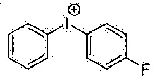
1-5 
1-10 
1-11 
1-12 
1-13 
1-14 
1-15 
1-16 
1-17 
1-18 
1-19 
3-1 
3-3 
3-2 
4-1 
4-3 
4-2 
5-1 
5-4 
5-2 
5-5 
5-3 
5-6 
6-1 
6-3 
6-2 
6-4 
- According to an exemplary embodiment of the present invention, the ionic compound is any one selected from the group consisting of the following chemical formulae.


- Hereinafter, an ink composition will be specifically described.
- An exemplary embodiment of the present invention provides an ink composition including: the compound represented by the above-described Chemical Formula 1; the first solvent represented by the above-described Chemical Formula A; and the second solvent represented by the above-described Chemical Formula B-1 or B-2.
- According to an exemplary embodiment of the present invention, the ink composition further includes an ionic compound including the anionic group represented by the above-described Chemical Formula 2.
- According to an exemplary embodiment of the present invention, the ionic compound further includes the above-described cationic group. That is, the ink composition further includes an ionic compound including the anionic group represented by the above-described Chemical Formula 2 and the above-described cationic group.
- According to an exemplary embodiment of the present invention, the ink composition further includes one or more additional solvents selected from the group consisting of tetralin, 4-methoxytoluene, tetrahydrofuran, dioxane, dipropylene glycol monomethyl ether and tripropylene glycol monomethyl ether.
- According to an exemplary embodiment of the present invention, the ink composition further includes one or more additional solvents selected from the group consisting of tetralin, 4-methoxytoluene, dipropylene glycol monomethyl ether and tripropylene glycol monomethyl ether.
- According to an exemplary embodiment of the present invention, the additional solvent has a viscosity of 1 cP to 15 cP.
- As an additional solvent having a viscosity within the above range is included, there is an advantage in that an ink composition having a viscosity suitable for an inkjet printing process can be prepared.
- An exemplary embodiment of the present invention provides an ink composition including: the compound represented by the above-described Chemical Formula 1; the first solvent represented by theabove-described Chemical Formula A; the second solvent represented by the above-described Chemical Formula B-1 or B-2; and an ionic compound including the anionic group represented by the above-described Chemical Formula 2; and the above-described additional solvent.
- An exemplary embodiment of the present invention provides an ink composition including: the compound represented by the above-described Chemical Formula 1; the first solvent represented by the above-described Chemical Formula A; the second solvent represented by the above-described Chemical Formula B-1 or B-2; the above-described ionic compound; and the above-described additional solvent, and the ionic compound includes the anionic group represented by the described-above Chemical Formula 2 and the above-described cationic group.
- According to an exemplary embodiment of the present invention, based on 100 wt% of the ink composition, the compound represented by Chemical Formula 1 is included in an amount of 0.1 wt% to 15 wt%; 0.1 wt% to 10 wt%; or 0.1 wt% to 5 wt%.
- According to an exemplary embodiment of the present invention, based on 100 wt% of the ink composition, the first solvent represented by Chemical Formula A is included in an amount of 1 wt% to 70 wt%; 1 wt% to 50 wt%; or 1 wt% to 30 wt%.
- According to an exemplary embodiment of the present invention, based on 100 wt% of the ink composition, the second solvent represented by Chemical Formula B-1 or B-2 is included in an amount of 10 wt% to 80 wt%; 10 wt% to 70 wt%; or 10 wt% to 50 wt%.
- According to an exemplary embodiment of the present invention, based on 100 wt% of the ink composition, the ionic compound including the anionic group represented by Chemical Formula 2 is included in an amount of 0.1 wt% to 15 wt%; 0.1 wt% to 10 wt%; or 0.1 wt% to 5 wt%.
- According to an exemplary embodiment of the present invention, based on 100 wt% of the ink composition, the compound represented by Chemical Formula 1 is included in an amount of 0.1 wt% to 15 wt%; the first solvent represented by Chemical Formula A is included in an amount of 1 wt% to 70 wt%; the second solvent represented by Chemical Formula B-1 or B-2 is included in an amount of 10 wt% to 80 wt%; and the ionic compound including the anionic group represented by Chemical Formula 2 is included in an amount of 0.1 wt% to 15 wt%.
- According to an exemplary embodiment of the present invention, the ink composition has a viscosity of 2 cP to 15 cP at room temperature. When the above viscosity is satisfied, a device is easily manufactured. Specifically, a uniform film may be formed when an organic material layer in an organic light emitting device is formed.
- The above viscosity is a value measured at room temperature using a viscometer manufactured by Brookfield Engineering Labs Inc. after dissolving an object to be measured at any one concentration of 1 wt% to 3 wt% in the first solvent and the second solvent, which are mixed at an arbitrary ratio. In this case, the object to be measured is a compound represented by Chemical Formula 1; or a mixture of the compound represented by Chemical Formula 1 and the above-described ionic compound.
- According to an exemplary embodiment of the present invention, the ink composition is a liquid phase. The "liquid phase" means that the composition is in a liquid state at room temperature under atmospheric pressure.
- In an exemplary embodiment of the present specification, the ink composition can be cured by a heat treatment or a light treatment. When the ink composition is cured, this may be expressed as a cured product of the ink composition.
- According to an exemplary embodiment of the present invention, the ink composition further includes: a single molecule including a photocurable group and/or a thermosetting group; or a single molecule including an end group capable of forming a polymer by heat. As described above, the single molecule including a photocurable group and/or a thermosetting group; or the single molecule including an end group capable of forming a polymer by heat may be a compound having a molecular weight of 3,000 g/mol or less, but the molecular weight is not limited to the exemplified molecular weight.
- The single molecule including a photocurable group and/or a thermosetting group; or the single molecule including an end group capable of forming a polymer by heat may mean aryl such as phenyl, biphenyl, fluorene, and naphthalene; arylamine; or a single molecule in which a photocurable group and/or a thermosetting group or an end group capable of forming a polymer by heat is substituted at fluorene.
- According to an exemplary embodiment of the present invention, the ink composition may further include another additional solvent (hereinafter, expressed as a third solvent) other than the above-described additional solvent. The third solvent may be one or more selected from the group consisting of a chlorine-based solvent such as chloroform, methylene chloride, 1,2-dichloroethane, 1,1,2-trichloroethane, chlorobenzene, and o-dichlorobenzene; an ether-based solvent such as tetrahydrofuran, dioxane, and dipropylene glycol monomethyl ether; an aromatic hydrocarbon-based solvent such as toluene, xylene, trimethylbenzene, and mesitylene; an aliphatic hydrocarbon-based solvent such as cyclohexane, methylcyclohexane, n-pentane, n-hexane, n-heptane, n-octane, n-nonane, and n-decane; a ketone-based solvent such as acetone, methyl ethyl ketone, cyclohexanone, isophorone, tetralone, decalone, and acetylacetone; an ester-based solvent such as ethyl acetate, butyl acetate, ethyl cellosolve acetate, and benzyl butyrate; a polyhydric alcohol such as ethylene glycol, ethylene glycol monobutyl ether, ethylene glycol monoethyl ether, ethylene glycol monomethyl ether, dimethoxy ethane, propylene glycol, diethoxymethane, triethylene glycol monoethyl ether, glycerin, and 1,2-hexanediol, and derivatives thereof; an alcohol-based solvent such as methanol, ethanol, propanol, isopropanol, and cyclohexanol; a sulfoxide-based solvent such as dimethyl sulfoxide; an amide-based solvent such as N-methyl-2-pyrrolidone and N,N-dimethylformamide; and tetralin. However, the third solvent is not limited to the above example, and is sufficient as long as the third solvent can dissolve or disperse the compound represented by the above-described Chemical Formula 1.
- Hereinafter, a pixel including the above-described ink composition or a curred product thereof will be specifically described.
- An exemplary embodiment of the present invention provides a pixel including an ink composition or a cured product thereof.
- The pixel may be included in an organic material layer, an organic light emitting diode, or an organic light emitting display device. Details of the organic material layer will be described below. Specifically, the organic light emitting display device includes a plurality of pixels composed of red (R), green (G), and blue (B) sub-pixels, and an organic light emitting diode (OLED) and a pixel circuit are located for each sub-pixel. An organic light emitting diode includes two electrodes (anode and cathode) and an organic light emitting layer located therebetween, and a pixel circuit includes at least two thin film transistors and at least one capacitor. The organic material layer, the organic light emitting diode, or the organic light emitting display device may include a bank. Preferably, the organic material layer, the organic light emitting diode, or the organic light emitting display device may include a line-shaped bank. The line-shaped bank may define a line-shaped pixel region and/or a sub-pixel region. In a normal case, the light emitting layer among the organic material layers is composed of a red light emitting layer, a green light emitting layer and a blue light emitting layer located in a red sub-pixel, a green sub-pixel and a blue sub-pixel, respectively. In this case, the above-described pixel may correspond to the pixel or sub-pixel. As a preferred exemplary embodiment, the pixel corresponds to the sub-pixel.
- According to an exemplary embodiment of the present invention, one or more of the pixels may be included in the above-described organic material layer, organic light emitting diode or organic light emitting display device.
- According to an exemplary embodiment of the present invention, the thickness uniformity V of the one or more pixels is 0.4 or less, and the thickness uniformity V satisfies the following Equation 1.

- In Equation 1,
- X(i) is the thickness of the i-th pixel,
- Xm' is the average value of X(i) in which i is 2 to n', and
- n' is an integer from 2 to 104.
- In the present invention, when the thickness uniformity Vis 0.4 or lower and the thickness uniformity V satisfies Equation 1, it means that the thickness uniformity V calculated using Equation 1 is 0.4 or lower.
- According to an exemplary embodiment of the present invention, the thickness uniformity is 0.01 to 0.4, or 0.02 to 0.4.
- In the present invention, a low thickness uniformity value means that the thicknesses of the pixels are uniformly formed. That is, it means that the lower the thickness uniformity value, the more uniformly the pixels are formed.
- According to an exemplary embodiment of the present invention, the thickness of the pixel may mean the thickness of the central portion of the pixel, and may be measured by an optical thickness measuring device. As the optical thickness measuring device, an optical profiler manufactured by Bruker or the like may be used, but the optical thickness measuring device is not limited thereto.
- An exemplary embodiment of the present invention provides an organic material layer including the above-described pixel. That is, an exemplary embodiment of the present invention provides an organic material layer including the above-described ink composition or a cured product thereof.
- Hereinafter, an organic material layer including the above-described pixel will be specifically described.
- According to an exemplary embodiment of the present invention, the organic material layer includes a plurality of the pixels. For example, the organic material layer includes an x-axis on which na pixels are aligned and a y-axis that is perpendicular to the x-axis and on which nb pixels are aligned, and na and nb are each an integer from 2 to 104.
- According to an exemplary embodiment of the present invention, na and nb are each 2 or higher; 5 or higher; 10 or higher; 20 or higher; or 40 or higher, 104 or lower; 103 or lower; or 102 or lower.
- According to an exemplary embodiment of the present invention, the organic material layer includes 2 or more; 4 or more; 10 or more; 20 or more; 40 or more; 80 or more; or 100 or more and 108 or less; 106 or less; 104 or less; or 103 or less pixels.
- According to an exemplary embodiment of the present invention, pixels included in the organic material layer are aligned in the form of a line. For example, as shown in
FIG. 2 , a plurality of pixels are aligned in a row to form a line. - According to an exemplary embodiment of the present invention, the organic material layer includes a plurality of lines in which the plurality of pixels are aligned in a row. For example, as shown in
FIG. 2 , a plurality of lines may be formed at regular intervals. For example, the y-axis on which the above-described nb pixels are aligned is one line, and it is possible to include as many lines as the number of pixels (na) included in the x-axis. - According to an exemplary embodiment of the present invention, the organic material layer includes na x nb pixels.
- According to an exemplary embodiment of the present invention, a plurality of pixels included in the organic material layer have a uniform thickness.
- According to an exemplary embodiment of the present invention, the organic material layer includes n' pixels, the thickness uniformity V of the n' pixels is 0.4 or lower, and the thickness uniformity V satisfies the above-described Equation 1.
- According to an exemplary embodiment of the present invention, n' is 2 to 104.
- According to an exemplary embodiment of the present invention, the organic material layer is included in an organic light emitting device.
- According to an exemplary embodiment of the present invention, the organic material layer is formed by a solution process.
- According to an exemplary embodiment of the present invention, the organic material layer is one or more layers selected from the group consisting of a hole injection layer, a hole transport layer, a hole injection and transport layer, an electron blocking layer, a light emitting layer, a hole blocking layer, an electron injection layer, an electron transport layer, and an electron injection and transport layer.
- According to an exemplary embodiment of the present invention, the organic material layer is one or more layers selected from the group consisting of a hole injection layer, a hole transport layer, a hole injection and transport layer, an electron blocking layer, and a light emitting layer.
- According to an exemplary embodiment of the present invention, the organic material layer is one or more layers selected from the group consisting of a hole injection layer, a hole transport layer, a hole injection and transport layer, and an electron blocking layer.
- According to an exemplary embodiment of the present invention, the ink composition is a composition for forming one or more layers selected from the group consisting of a hole injection layer, a hole transport layer, a hole injection and transport layer, and an electron blocking layer.
- According to a preferred exemplary embodiment of the present invention, the organic material layer is a hole injection layer, a hole transport layer or an electron blocking layer.
- Hereinafter, an organic light emitting device will be specifically described.
- An exemplary embodiment of the present invention provides an organic light emitting device including: a first electrode; a second electrode; and an organic material layer having one or more layers provided between the first electrode and the second electrode, in which one or more layers of the organic material layer include the above-described ink composition or a cured product thereof.
- According to an exemplary embodiment of the present invention, the organic material layer includes one or more layers selected from the group consisting of a hole injection layer, a hole transport layer, a hole injection and transport layer, an electron blocking layer, a light emitting layer, a hole blocking layer, an electron injection layer, an electron transport layer, and an electron injection and transport layer, and the one or more layers selected from the group consisting of the hole injection layer, the hole transport layer, the hole injection and transport layer, the electron blocking layer, the light emitting layer, the hole blocking layer, the electron injection layer, the electron transport layer, and the electron injection and transport layer include the ink composition or a cured product thereof.
- According to an exemplary embodiment of the present invention, the organic material layer includes one or more layers selected from the group consisting of a hole injection layer, a hole transport layer, a hole injection and transport layer, and an electron blocking layer, and the one or more layers selected from the group consisting of the hole injection layer, the hole transport layer, the hole injection and transport layer, and the electron blocking layer include the ink composition or a cured product thereof.
- According to a preferred exemplary embodiment of the present invention, the organic material layer includes a hole injection layer, a hole transport layer, or an electron blocking layer, and the hole injection layer, the hole transport layer, or the electron blocking layer includes the ink composition or a cured product thereof.
- According to an exemplary embodiment of the present invention, the organic material layer included in the organic light emitting device includes n' of the above-described pixels, the thickness uniformity V of the n' pixels is 0.4 or lower, and the thickness uniformity V satisfies the above-described Equation 1.
- Hereinafter, a method for manufacturing an organic light emitting device will be specifically described.
- An exemplary embodiment of the present invention provides a method for manufacturing an organic light emitting device, the method including: preparing a first electrode;
- forming an organic material layer having one or more layers on the first electrode; and
- forming a second electrode on the organic material layer having one or more layers,
- in which the forming of the organic material layer includes forming an organic material layer using the above-described ink composition.
- According to an exemplary embodiment of the present invention, the forming of the organic material layer using the ink composition may form the organic material layer on a substrate including a line-shaped bank or an organic material layer.
- As an example, the above-described ink composition is applied (
FIG. 3 ) on a substrate including a line-shaped bank (FIG. 2 ), and then a thin film in which the ink composition is dried and/or heat-treated (FIG. 4 ) may be formed. - According to another exemplary embodiment of the present invention, the forming of the organic material layer using the ink composition uses a spin coating method.
- According to still another exemplary embodiment of the present invention, the forming of the organic material layer using the ink composition uses a printing method.
- According to an exemplary embodiment of the present invention, examples of the printing method include inkjet printing, nozzle printing, offset printing, transfer printing, screen printing, or the like, but are not limited to the printing methods listed above.
- According to an exemplary embodiment of the present invention, the forming of the organic material layer using the ink composition uses an inkjet printing method.
- A solution process is suitable for the ink composition according to an exemplary embodiment of the present invention due to the composition and structural characteristics of materials included, so that the organic material layer may be formed by a printing method, and as a result, there is an economic effect in terms of time and costs when a device is manufactured.
- According to an exemplary embodiment of the present invention, the forming of the organic material layer on the first electrode may further include drying after one or more steps of pressure reduction. As an example, the forming of the organic material layer on the first electrode further includes drying after two steps of pressure reduction. In this case, the drying after the first pressure reduction is performed under normal pressure to 2×10⁻² torr, and the pressure reduction time under normal pressure to 2×10⁻² torr may be 30 seconds to 600 seconds. Further, the drying after the second pressure reduction is performed under 2×10⁻² to 2×10⁻⁶ torr, and the pressure reduction time under 2×10⁻² torr to 2×10⁻⁶ torr may also be 30 seconds to 600 seconds.
- According to an exemplary embodiment of the present invention, the forming of the organic material layer using the ink composition includes: coating the ink composition; and heat-treating or light-treating the coated ink composition.
- According to an exemplary embodiment of the present invention, the forming of the organic material layer using the ink composition includes: coating the first electrode or the organic material layer having one or more layers with the ink composition; and heat-treating or light-treating the coated ink composition.
- According to an exemplary embodiment of the present invention, the heat-treating of the ink composition may be performed through a heat treatment, and the heat treatment temperature in the heat-treating of the ink composition may be 85°C to 250°C, may be 100°C to 250°C according to an exemplary embodiment, and may be 150°C to 250°C in another exemplary embodiment.
- According to an exemplary embodiment of the present invention, the heat treatment time in the heat-treating of the ink composition may be in a range of 10 minutes to 2 hours, may be in a range of 10 minutes to 1 hour according to an exemplary embodiment, and may be in a range of 20 minutes to 1 hour in another exemplary embodiment.
- When the forming of the organic material layer using the ink composition includes the heat-treating or light-treating of the ink composition, a plurality of the compounds included in the ink composition may form a cross-linkage, thereby providing an organic material layer including a thin-filmed structure. In this case, it is possible to prevent the organic material layer from being dissolved, morphologically affected or decomposed by a solvent when another layer is stacked on the surface of the organic material layer formed using the ink composition.
- Therefore, when the organic material layer formed using the ink composition is formed by a method including the subjecting of the organic material layer to the heat treatment or the light treatment, resistance to a solvent is increased, so that a plurality of layers may be formed by repeatedly carrying out solution deposition and cross-linking methods, and stability is increased, so that service life characteristics of the device may be increased.
- Hereinafter, the types of organic material layers included in the above-described organic light emitting device will be specifically described.
- According to an exemplary embodiment of the present invention, the organic light emitting device includes an organic material layer having one layer, and the organic material layer includes the above-described ink composition or a cured product thereof.
- According to another exemplary embodiment of the present invention, the organic light emitting device includes an organic material layer having two or more layers, and the organic material layer having two or more layers includes the above-described ink composition or a cured product thereof. For example, among organic material layers having two or more layers, the organic material layer having any one layer includes the ink composition or a cured product thereof, and further includes the organic material layer having the other layer or more. The organic material layer having the other layer or more according to an exemplary embodiment does not include the ink composition or a cured product thereof. The organic material layer having the other layer or more according to another exemplary embodiment further includes the ink composition or a cured product thereof. However, the organic material layer having the other layer or more is not limited to the examples.
- The organic material layer having two or more layers includes two or more layers selected from the group consisting of, for example, a hole injection layer, a hole transport layer, a hole injection and transport layer, an electron blocking layer, a light emitting layer, a hole blocking layer, an electron transport layer, an electron injection layer, an electron injection and transport layer, and the like. In this case, the hole injection and transport layer means a layer which simultaneously injects and transports holes, and the electron injection and transport layer means a layer which simultaneously injects and transports electrons. However, the organic material layers forming the group are merely an example, and are not limited to the above example. Further, the organic material layer having two or more layers may include two or more layers that play the same role, if necessary. The organic light emitting device according to an exemplary embodiment includes a first hole injection layer and a second hole injection layer. However, the organic light emitting device is not limited to the examples.
- According to an exemplary embodiment of the present invention, the organic material layer includes a light emitting layer. As an example, the light emitting layer includes the ink composition or a cured product thereof . As a specific example, the light emitting layer includes the ink composition or a cured product thereof as a host of the light emitting layer. As another specific example, the light emitting layer includes the ink composition or a cured product thereof as a dopant of the light emitting layer.
- According to an exemplary embodiment of the present invention, the organic material layer includes a hole injection and transport layer, a hole injection layer, a hole transport layer and an electron blocking layer. As an example, the hole injection and transport layer, the hole injection layer, the hole transport layer or the electron blocking layer includes an ink composition or a cured product thereof.
- According to a preferred exemplary embodiment of the present invention, the organic material layer includes a hole transport layer or an electron blocking layer. As an example, the hole transport layer or the electron blocking layer includes the ink composition or a cured product thereof.
- According to a preferred exemplary embodiment of the present invention, the organic material layer includes a hole injection layer and a hole transport layer.
- According to an exemplary embodiment of the present invention, the organic material layer further includes one or more layers selected from the group consisting of a hole blocking layer, an electron transport layer, an electron injection layer, and an electron injection and transport layer. As an example, one or more layers selected from the group consisting of the hole blocking layer, the electron transport layer, the electron injection layer, and the electron injection and transport layer include the ink composition or a cured product thereof. As another example, one or more layers selected from the group consisting of the hole blocking layer, the electron transport layer, the electron injection layer, and the electron injection and transport layer do not include an ink composition or a cured product thereof.
- An exemplary embodiment of the present invention provides an organic light emitting device including: a first electrode; a second electrode; and an organic material layer having one or more layers provided between the first electrode and the second electrode, in which the organic material layer includes a light emitting layer and a hole injection layer, and the hole injection layer includes the ink composition or a cured product thereof.
- Hereinafter, the stacking structure of the organic material layer and the organic light emitting device including the organic material layer will be specifically described.
- The organic material layer of the organic light emitting device according to an exemplary embodiment of the present invention has a single-layered structure. For example, the organic material layer having the single-layered structure is provided between the first electrode and the second electrode of the organic light emitting device, and includes the ink composition or a cured product thereof. According to a specific exemplary embodiment, the organic material layer having the single-layered structure is a light emitting layer, and in this case, the light emitting layer includes the ink composition or a cured product thereof.
- The organic material layer of the organic light emitting device according to another exemplary embodiment of the present invention has a multi-layered structure in which an organic material layer having two or more layers is stacked. For example, the organic material layer having the multi-layered structure is provided between the first electrode and the second electrode of the organic light emitting device.
- According to an exemplary embodiment of the present invention, the organic material layer having the multi-layered structure includes a light emitting layer and an organic material layer other than the light emitting layer. As an example, the light emitting layer is provided between the first electrode and the second electrode, and the organic material layer other than the light emitting layer is provided between the first electrode and the light emitting layer. As another example, the light emitting layer is provided between the first electrode and the second electrode, and the organic material layer other than the light emitting layer is provided between the light emitting layer and the second electrode. As still another example, the light emitting layer is provided between the first electrode and the second electrode, any one organic material layer other than the light emitting layer is provided between the first electrode and the light emitting layer, and the other organic material layer other than the light emitting layer is provided between the light emitting layer and the second electrode. However, the above structure is merely an example, and the structure is not limited to the above structure . Further, the organic material layer other than the light emitting layer may be one or more layers selected from the group consisting of, for example, a hole injection and transport layer, a hole injection layer, a hole transport layer, an electron blocking layer, a hole blocking layer, an electron transport layer, an electron injection layer, an electron injection and transport layer, and the like, but is not limited thereto.
- In general, a hole injection layer, a hole transport layer or an electron blocking layer in an organic light emitting device is provided between an anode and a light emitting layer. As a specific example, the hole injection layer is provided on the anode, the hole transport layer is provided on the hole injection layer, and the electron blocking layer is provided on the hole injection layer, but the present invention is not limited to the above examples.
- Further, in general, an electron injection layer, an electron transport layer or a hole blocking layer in an organic light emitting device is provided between a cathode and a light emitting layer. As a specific example, the hole blocking layer is provided on the light emitting layer, the electron transport layer is provided on the hole blocking layer, and the electron injection layer is provided on the electron transport layer, but the present invention is not limited to the above examples.
- The organic material layer having a multi-layered structure included in the organic light emitting device according to an exemplary embodiment of the present invention includes: one or more layers selected from the group consisting of a hole injection and transport layer, a hole injection layer, a hole transport layer, an electron blocking layer, a hole blocking layer, an electron transport layer, an electron injection layer, and an electron injection and transport layer; and a light emitting layer, the light emitting layer is provided between a first electrode and a second electrode, the one or more layers are provided between the first electrode and the light emitting layer or between the second electrode and the light emitting layer, and the one or more layers include an ink composition or a cured product thereof.
- The structure of the organic light emitting device according to an exemplary embodiment of the present invention is illustrated in
FIG. 1. FIG. 1 exemplifies a structure of an organic light emitting device in which afirst electrode 201, ahole injection layer 301, ahole transport layer 401, alight emitting layer 501, an electron injection andtransport layer 601, and asecond electrode 701 are sequentially stacked on asubstrate 101. Thehole injection layer 301 and/or thehole transport layer 401 ofFIG. 1 include/includes the above-described ink composition or a cured product thereof, or may be formed using the ink composition. In this case, for thehole injection layer 301 and/or thehole transport layer 401 ofFIG. 1 , a specific content of the organic material layer which may be formed using the ink composition, a material thereof and a manufacturing method thereof will described below. In addition,FIG. 1 exemplifies the organic light emitting device according to an exemplary embodiment of the present invention, and the organic light emitting device is not limited thereto. - As described above, an organic light emitting device having an organic material layer having a single-layered or multi-layered structure may have, for example, the following stacking structure, but the stacking structure is not limited thereto.
- (1) Anode/Hole transport layer/Light emitting layer/Cathode
- (2) Anode/Hole injection layer/Hole transport layer/Light emitting layer/Cathode
- (3) Anode/Hole injection layer/Hole buffer layer/Hole transport layer/Light emitting layer/Cathode
- (4) Anode/Hole transport layer/Light emitting layer/Electron transport layer/Cathode
- (5) Anode/Hole transport layer/Light emitting layer/Electron transport layer/Electron injection layer/Cathode
- (6) Anode/Hole injection layer/Hole transport layer/Light emitting layer/Electron transport layer/Cathode
- (7) Anode/Hole injection layer/Hole transport layer/Light emitting layer/Electron transport layer/Electron injection layer/Cathode
- (8) Anode/Hole injection layer/Hole buffer layer/Hole transport layer/Light emitting layer/Electron transport layer/Cathode
- (9) Anode/Hole injection layer/Hole buffer layer/Hole transport layer/Light emitting layer/Electron transport layer/Electron injection layer/Cathode
- (10) Anode/Hole transport layer/Electron blocking layer/Light emitting layer/Electron transport layer/Cathode
- (11) Anode/Hole transport layer/Electron blocking layer/Light emitting layer/Electron transport layer/Electron injection layer/Cathode
- (12) Anode/Hole injection layer/Hole transport layer/Electron blocking layer/Light emitting layer/Electron transport layer/Cathode
- (13) Anode/Hole injection layer/Hole transport layer/Electron blocking layer/Light emitting layer/Electron transport layer/Electron injection layer/Cathode
- (14) Anode/Hole transport layer/Light emitting layer/Hole blocking layer/Electron transport layer/Cathode
- (15) Anode/Hole transport layer/Light emitting layer/Hole blocking layer/Electron transport layer/Electron injection layer/Cathode
- (16) Anode/Hole injection layer/Hole transport layer/Light emitting layer/Hole blocking layer/Electron transport layer/Cathode
- (17) Anode/Hole injection layer/Hole transport layer/Light emitting layer/Hole blocking layer/Electron transport layer/Electron injection layer/Cathode
- (18) Anode/Hole injection layer/Hole transport layer/Light emitting layer/Hole blocking layer/Electron transport layer/Electron injection layer/Cathode/Capsule
- (19) Anode/Hole injection layer/First hole transport layer/Second hole transport layer/Light emitting layer/Hole blocking layer/Electron transport layer/Electron injection layer/Cathode/Capsule
- In the structures, the 'Electron transport layer/Electron injection layer' may be replaced with an 'electron injection and transport layer' or a 'layer that simultaneously injects and transports electrons'.
- Further, in the structures, the 'Hole injection layer/Hole transport layer' may be replaced with the 'hole injection and transport layer' or the "layer which simultaneously injects and transports holes".
- According to an exemplary embodiment of the present invention, the first electrode is an anode, and the second electrode is a cathode.
- According to another exemplary embodiment of the present invention, the first electrode is a cathode, and the second electrode is an anode.
- According to an exemplary embodiment of the present invention, the organic light emitting device may be a normal type organic light emitting device in which an anode, an organic material layer having one or more layers, and a cathode are sequentially stacked on a substrate.
- According to another exemplary embodiment of the present invention, the organic light emitting device may be an inverted type organic light emitting device in which a cathode, an organic material layer having one or more layers, and an anode are sequentially stacked on a substrate.
- Hereinafter, the specific content of the above-described organic material layer, a material thereof, and a manufacturing method thereof will be described. However, the organic light emitting device of the present invention may be manufactured by materials and methods known in the art, except that the organic material layer includes the above-described compound.
- In an organic light emitting device according to an exemplary embodiment of the present invention, one or more layers of the organic material layer are formed using the ink composition or a cured product thereof. Except for this, the organic light emitting device may be manufactured by materials and methods known in the art.
- For example, the organic light emitting device of the present invention may be manufactured by sequentially stacking an anode, an organic material layer, and a cathode on a substrate. In this case, the organic light emitting device may be manufactured by depositing a metal or a metal oxide having conductivity, or an alloy thereof on a substrate to form an anode, forming an organic material layer including one or more layers of a hole injection layer, a hole transport layer, a light emitting layer, an electron injection layer, an electron transport layer, a hole transport and injection layer, and an electron injection and transport layer thereon through a solution process, a deposition process, the like, and then depositing a material, which may be used as a cathode, thereon, by using a physical vapor deposition (PVD) method such as sputtering or e-beam evaporation. In addition to the method described above, an organic light emitting device may be made by sequentially depositing a cathode material, an organic material layer, and an anode material on a substrate.
- As the anode material, materials having a high work function are usually preferred so as to facilitate the injection of holes into an organic material layer. Examples thereof include: a metal, such as vanadium, chromium, copper, zinc, and gold, or an alloy thereof; a metal oxide, such as zinc oxide, indium oxide, indium tin oxide (ITO), and indium zinc oxide (IZO) ; a combination of a metal and an oxide, such as ZnO:Al or SnO2:Sb; a conductive polymer, such as poly(3-methylthiophene), poly[3,4-(ethylene-1,2-dioxy)thiophene] (PEDOT), polypyrrole, and polyaniline; and the like, but are not limited thereto.
- As the cathode material, materials having a low work function are usually preferred so as to facilitate the injection of electrons into an organic material layer. Examples thereof include: a metal, such as magnesium, calcium, sodium, potassium, titanium, indium, yttrium, lithium, gadolinium, aluminum, silver, tin, and lead, or an alloy thereof; a multi-layer structured material, such as LiF/Al or LiO2/Al; and the like, but are not limited thereto.
- The light emitting layer may include a host material and/or a dopant material.
- Examples of the host material include a fused aromatic ring derivative, a hetero ring-containing compound, or the like. Specific examples of the fused aromatic ring derivative include anthracene derivatives, pyrene derivatives, naphthalene derivatives, pentacene derivatives, phenanthrene compounds, fluoranthene compounds, and the like, and specific examples of the hetero ring-containing compound include dibenzofuran derivatives, ladder-type furan compounds, pyrimidine derivatives, and the like, but the examples are not limited thereto.
- Examples of the dopant material include an aromatic amine derivative, a styrylamine compound, a boron complex, a fluoranthene compound, a metal complex, and the like. Specifically, the aromatic amine derivative is a fused aromatic ring derivative having a substituted or unsubstituted arylamine group, and examples thereof include pyrene, anthracene, chrysene, periflanthene, and the like having an arylamine group. Further, the styrylamine compound is a compound in which a substituted or unsubstituted arylamine is substituted with at least one arylvinyl group, and one or two or more substituents selected from the group consisting of an aryl group, a silyl group, an alkyl group, a cycloalkyl group, and an arylamine group are substituted or unsubstituted. Specific examples thereof include styrylamine, styryldiamine, styryltriamine, styryltetramine, and the like, but are not limited thereto. Further, examples of the metal complex include an iridium complex, a platinum complex, and the like, but are not limited thereto.
- The hole injection layer is a layer which accepts holes from an electrode. It is preferred that hole injection material has an ability to transport holes, and has an effect of accepting holes from an anode and an excellent hole injection effect for a light emitting layer or a light emitting material. Further, the hole injection material is preferably a material which is excellent in ability to prevent excitons produced from a light emitting layer from moving to an electron injection layer or an electron injection material. In addition, the hole injection material is preferably a material which is excellent in ability to form a thin film. In addition, the HOMO of the hole injection material is preferably a value between the work function of the anode material and the HOMO of the neighboring organic material layer. Specific examples of the hole injection material include: metal porphyrin, oligothiophene, and arylamine-based organic materials; hexanitrile hexaazatriphenylene-based organic materials; quinacridone-based organic materials; perylene-based organic materials; polythiophene-based conductive polymers such as anthraquinone and polyaniline; and the like, but are not limited thereto.
- The hole transport layer is a layer which accepts holes from a hole injection layer and transports the holes to a light emitting layer, and may have a single-layered structure or a multi-layered structure having two or more layers. A hole transport material is preferably a material having high hole mobility which may accept holes from an anode or a hole injection layer and transfer the holes to a light emitting layer. In the present invention, the compound represented by the above-described Chemical Formula 1 may be included as a hole transport material. Furthermore, it is possible to further include other hole transport materials in addition to the compound represented by Chemical Formula 1, if necessary. Specific examples thereof include arylamine-based organic materials, carbazole-based compounds, conductive polymers, block copolymers having both conjugated portions and non-conjugated portions, and the like, but are not limited thereto. According to an exemplary embodiment of the present invention, the hole transport material is the ink composition or a cured product thereof.
- The electron transport layer is a layer which accepts electrons from an electron injection layer and transports the electrons to a light emitting layer. An electron transport material is preferably a material having high electron mobility which may proficiently accept electrons from a cathode and transfer the electrons to a light emitting layer. Specific examples thereof include: Al complexes of 8-hydroxyquinoline; complexes including Alq3; organic radical compounds; hydroxyflavone-metal complexes; and the like, but are not limited thereto. The electron transport layer may be used with any desired cathode material, as used according to the related art. In particular, an appropriate cathode material is a typical material which has a low work function, followed by an aluminum layer or a silver layer. Specific examples thereof include cesium, barium, calcium, ytterbium, and samarium, in each case followed by an aluminum layer or a silver layer.
- The electron injection layer is a layer which accepts electrons from an electrode. It is preferred that an electron injection material is excellent in ability to transport electrons and has an effect of accepting electrons from the cathode and an excellent electron injection effect for a light emitting layer or a light emitting material. Further, the electron injection material is preferably a material which prevents excitons produced from a light emitting layer from moving to a hole injection layer and is excellent in ability to form a thin film. Specific examples thereof include fluorenone, anthraquinodimethane, diphenoquinone, thiopyran dioxide, oxazole, oxadiazole, triazole, imidazole, perylenetetracarboxylic acid, fluorenylidenemethane, anthrone, and the like, and derivatives thereof, metal complex compounds, nitrogen-containing 5-membered ring derivatives, and the like, but are not limited thereto. Examples of the metal complex compounds include 8-hydroxyquinolinato lithium, bis(8-hydroxyquinolinato) zinc, bis(8-hydroxyquinolinato) copper, bis(8-hydroxyquinolinato) manganese, tris(8-hydroxyquinolinato) aluminum, tris(2-methyl-8-hydroxyquinolinato) aluminum, tris(8-hydroxyquinolinato) gallium, bis(10-hydroxybenzo[h]quinolinato) beryllium, bis(10-hydroxybenzo[h]quinolinato) zinc, bis(2-methyl-8-quinolinato) chlorogallium, bis(2-methyl-8-quinolinato) (o-cresolato) gallium, bis(2-methyl-8-quinolinato) (1-naphtholato) aluminum, bis(2-methyl-8-quinolinato) (2-naphtholato) gallium, and the like, but are not limited thereto. The electron blocking layer is a layer which may improve the service life and efficiency of a device by preventing electrons injected from an electron injection layer from passing through a light emitting layer and entering a hole injection layer. The electron-blocking layer may be formed between the light emitting layer and the hole injection layer, or between the light emitting layer and the layer which simultaneously injects and transports holes using the compound of the above-described Chemical Formula 2.
- The hole blocking layer is a layer which blocks holes from reaching a cathode, and may be generally formed under the same conditions as those of the electron injection layer. Specific examples of the hole blocking layer material include oxadiazole derivatives or triazole derivatives, phenanthroline derivatives, aluminum complexes, and the like, but are not limited thereto.
- The hole injection and transport layer may include materials for the above-described hole injection layer and hole transport layer.
- The electron injection and transport layer may include materials for the above-described electron injection layer and electron transport layer.
- When the organic light emitting device includes a plurality of organic material layers, the organic material layers may be formed of the same material or different materials.
- The organic light emitting device according to the present invention may be a top emission type, a bottom emission type, or a dual emission type according to the material to be used.
- An exemplary embodiment of the present invention provides an electronic device including an organic light emitting device including the above-described ink composition or a cured product thereof, or including an organic material layer formed using the ink composition.
- The electronic device may include all of the interlayer insulation film of a semiconductor device, a color filter, a black matrix, an overcoat, a column spacer, a passivation film, a buffer coating film, a multilayer printed board insulation film, a cover coat of a flexible copper-clad board, a buffer coating film, a multilayer printed board insulation film, a solder resist film, an insulation film of OLED, a protection film of a thin-film transistor of a liquid crystal display device, an electrode protection film and a semiconductor protection film of an organic EL device, an OLED insulation film, an LCD insulation film, a semiconductor insulation film, a solar light module, a touch panel, a display device such as a display panel, and the like, but is not limited thereto.
- Hereinafter, the present invention will be described in detail with reference to Examples for specifically describing the present invention. However, the Examples according to the present invention may be modified into various different forms, and it should not be interpreted that the scope of the present invention is limited to the Examples to be described below. The Examples of the present invention are provided for more completely explaining the present invention to the person with ordinary skill in the art.
-

- 1-bromo-3-fluorobenzene (27.9 mL, 255 mmol) was put into tetrahydrofuran (THF) (500 mL). After substitution with nitrogen, the mixture was cooled to -78°C. n-BuLi (2.5 M Hex) (96 mL, 240 mmol) was put into a dropping funnel and then slowly introduced into the reaction mixture. The resulting mixture was stirred at -78°C for 30 minutes. 2-bromofluorenone (38.9 g, 150 mmol) was added thereto . The mixture was stirred overnight while being slowly warmed to room temperature. After the reaction was terminated by adding distilled water thereto, extraction was performed with ethyl acetate and water. After an organic layer was collected, the organic layer was dried using MgSO4 and filtered. The filtrate was dried using a vacuum rotary concentrator to remove the organic solvent, and Intermediate 1-1 was secured and used in the next reaction.
-

- Intermediate 1-1 (53 g, 150 mmol) and phenol (70.6 g, 750 mmol) were put into a round bottom flask (RBF) . After CH3SO3H (214 mL) was added thereto, the resulting mixture was stirred at 60°C for 4 hours. After ice water was added thereto, extraction was performed with ethyl acetate and water. After an organic layer was collected, the organic layer was dried using MgSO4 and filtered. The filtrate was dried using a vacuum rotary concentrator to remove the organic solvent. After column purification, crystallization was performed under dichloromethane/heptane conditions to secure 40.6 g of Intermediate 1-2.
-

- Intermediate 1-2 (40 g, 92.7 mmol), 4-nitrobenzaldehyde (21.2 g, 139 mmol), Cu(OAc)2 (842 mg, 4.64 mmol) and Cs2CO3 (45.3 g, 139 mmol) were put into RBF. Dimethylformamide (DMF) (310 mL) was added thereto, and the resulting mixture was stirred at100°C for4 hours . Extraction was performed with ethyl acetate and water, an organic layer was collected, and then the organic layer was dried using MgSO4 and then filtered. The filtrate was dried using a vacuum rotary concentrator to remove the organic solvent. After column purification, crystallization was performed under DCM/heptane conditions to secure 38.7 g of Intermediate 1-3.
-

- After CH3PPh3Br (51.6 g, 144.6 mmol), KOtBu (16.2 g, 144.6 mmol) and THF (217 mL) were put into RBF, the resulting mixture was cooled to 0°C. A solution of Intermediate 1-3 (38.7 g, 72.3 mmol) dissolved in tetrahydrofuran (THF) (144 mL) was added to the reaction mixture. The resulting mixture was stirred for 1 hour while being warmed to room temperature. Extraction was performed with ethyl acetate and water, an organic layer was collected, and then the organic layer was dried using MgSO4 and then filtered. The filtrate was dried using a vacuum rotary concentrator to remove the organic solvent. After column purification, crystallization was performed under DCM/EtOH conditions to secure 33.7 g of Intermediate 1-4.
-

- N,N'-bis(4-fluorophenyl)benzidine (944 mg, 2.5 mmol), Intermediate 1-4 (2.73 g, 5.13 mmol), Pd(PtBu3)2 (64 mg, 0.125 mmol) and NaOtBu (961 mg, 10 mmol) were put into RBF. After substitution with nitrogen, toluene (12.5 mL) was added thereto, and the resulting mixture was stirred at 90°C for 1 hour. Extraction was performed with ethyl acetate and water, an organic layer was collected, and then the organic layer was dried using MgSO4 and then filtered. The filtrate was dried using a vacuum rotary concentrator to remove the organic solvent. After column purification, crystallization was performed under DCM/EtOH conditions to obtain 2.7 g of Compound 1. The synthesis of the compound was confirmed through LC-MS and NMR. MS: [M+H] + = 1277 NMR measurement value of Compound 1: 1H NMR (500 MHz, DMSO-d6) δ 7.83 (m, 4H), 7.45 - 7.36 (m, 12H), 7.27 (t, 2H), 7.17 - 6.86 (m, 36H), 6.65 - 6.57 (m, 2H), 5.65 (dd, 2H), 5.11 (dd, 2H)
-


- Intermediate 2-1 was prepared in the same manner as in (1) of Synthesis Example A-1, except that 1-bromo-4-fluorobenzene was used instead of 1-bromo-3-fluorobenzene in (1) of Synthesis Example A-1. Thereafter, Intermediate 2-4 was finally secured by preparing intermediates in the same manner as in (2) to (4) of Synthesis Example A-1, except that Intermediates 2-1, 2-2 and 2-3 were used instead of Intermediates 1-1, 1-2 and 1-3, respectively, in (2) to (4) of Synthesis Example A-1.
-

- Compound 2 was secured in the same manner as in (5) of Synthesis Example A-1, except that Intermediate 2-4 was used instead of Intermediate 1-4 in (5) of Synthesis Example A-1. The synthesis of the compound was confirmed through LC-MS and NMR. MS: [M+H]+ = 1277
- NMR measurement value of Compound 2: 1H NMR (500 MHz, DMSO-d6) δ 7.83 (m, 4H), 7.45 - 7.36 (m, 12H), 7.27 (t, 2H), 7.17 - 6.86 (m, 36H), 6.65 - 6.57 (m, 2H), 5.65 (dd, 2H), 5.11 (dd, 2H)
-


- Intermediate 3-1 was prepared in the same manner as in (1) of Synthesis Example A-1, except that 4-bromo-1,2-difluorobenzene was used instead of 1-bromo-3-fluorobenzene in (1) of Synthesis Example A-1. Thereafter, Intermediate 3-4 was finally secured by preparing intermediates in the same manner as in (2) to (4) of Synthesis Example A-1, except that Intermediates 3-1, 3-2 and 3-3 were used instead of Intermediates 1-1, 1-2 and 1-3, respectively, in (2) to (4) of Synthesis Example A-1.
-

- Compound 3 was secured in the same manner as in (5) of Synthesis Example A-1, except that Intermediate 3-4 was used instead of Intermediate 1-4 in (5) of Synthesis Example A-1. The synthesis of the compound was confirmed through LC-MS and NMR. MS: [M+H]+ = 1313
- NMR measurement value of Compound 3: 1H NMR (500 MHz, DMSO-d6) δ 7.87 (t, 4H), 7.50 (d, 4H), 7.44 - 7.27 (m, 12H), 7.11 - 7.00 (m, 22H) 6.94 - 6.83 (m, 10H), 6.66 - 6.59 (m, 2H), 5.66 (dd, 2H), 5.12 (dd, 2H)
-

- 2,2'-bis(4-fluorophenylamino)-9,9'-spirobi[9H-fluorene ] (1.34 g, 2.5 mmol), Intermediate 2-4 (2.73 g, 5.13 mmol), Pd(PtBu3)2 (64 mg, 0.125 mmol) and NaOtBu (961 mg, 10 mmol) were put into RBF. After substitution with nitrogen, toluene (12.5 mL) was added thereto, and the resulting mixture was stirred at 90°C for 1 hour. Extraction was performed with ethyl acetate and water, an organic layer was collected, and then the organic layer was dried using MgSO4 and then filtered. The filtrate was dried using a vacuum rotary concentrator to remove the organic solvent. After column purification, crystallization was performed under DCM/EtOH conditions to secure 2.9 g of Compound 4. The synthesis of the compound was confirmed through LC-MS and NMR. MS: [M+H]+ = 1440
- NMR measurement value of Compound 4: 1H NMR (500 MHz, DMSO-d6) δ 7.80 - 7.74 (m, 6H), 7.69 (d, 2H), 7.44 - 7.33 (m, 8H), 7.30 - 7.24 (m, 4H), 7.06 - 6.80 (m, 36H), 6.71 - 6.63 (m, 2H), 6.56 (m, 2H), 6.30 - 6.28 (m, 2H), 5.70 (dd, 2H), 5.17 (dd, 2H)
-

- Compound 5 was prepared in the same manner as in Synthesis Example A-4, except that 2,2'-bis(3,4-difluorophenylamino)-9,9'-spirobi[9H-fluorene] was used instead of 2,2'-bis(4-fluorophenylamino)-9,9'-spirobi[9H-fluorene] in Synthesis Example A-4. The synthesis of the compound was confirmed through LC-MS and NMR. MS: [M+H]+ = 1475
- NMR measurement value of Compound 5: 1H NMR (500 MHz, DMSO-d6) δ 7.79 - 7.73 (m, 6H), 7.69 - 7.66 (m, 2H), 7.44 - 7.40 (m, 6H), 7.36 - 7.22 (m, 8H), 7.08 - 6. 85 (m, 22H), 6.85 - 6.67 (m, 10H), 6.71 - 6.63 (m, 2H), 6.58 - 6.55 (m, 2H), 6.26 (m, 2H), 5.70 (dd, 2H), 5.17 (dd, 2H)
-

- 1-bromo-2,3,5,6-tetrafluoro-4-vinylbenzene (2 g, 7.84 mmol) was put into THF (20 mL) in a 50-mL round bottom flask, and the resulting solution was stirred at -78°C for 30 minutes. n-BuLi in hexane (3.45 mL, 8.63 mmol, 2.5 M) was slowly added to the solution, and the resulting mixture was stirred at -78°C for 30 minutes. BCl3 (2.6 mL, 2.61 mmol, 1 M in heptane solution) was added to the reaction solution at -78°C for 15 minutes. The resulting solution was slowly warmed to room temperature, the reaction solution was stirred overnight, and then water (30 mL) was added thereto. After the synthetic material was extracted with ethyl acetate (three times with 10 mL), the solvent was thoroughly removed. Water was completely removed by means of a Dean-stark using benzene, and the solid was filtered to prepare Intermediate D-1-1 (800 mg, yield 43%).
-

- Intermediate D-1-1 (400 mg, 0.56 mmol), diphenyliodonium chloride (176 mg, 0.56 mmol), water (10 mL), and acetone (10 mL) were put into a 25-mL round bottom flask and stirred vigorously for 30 minutes. Extraction was performed using dichloromethane (three times with 10 mL) to remove the solvent, and the residue was dried to prepare Compound D-1 (Dopant 1) (552 mg, yield 100%) .
- MS: [M-H]- = 711 (negative mode)
- MS: [M+H]+ = 281 (positive mode)
-

- Mg (193 mg, 7.92 mmol), I2 (4 mg), and THF (10 mL) were put into a 100-mL round bottom flask under a nitrogen atmosphere, and stirred for 30 minutes. 4-bromostyrene (1.04 mL, 7.92 mmol) was put thereinto, a water bath at 30 °C was placed under the round bottom flask, and the resulting mixture was stirred overnight. It was confirmed that the reaction solution had become black and Mg had been dissolved therein. The reaction solution was diluted by adding ether (5 mL) thereto. Tris(pentafluorophenyl)borane (1 g, 3.96 mmol) was dissolved in ether (5 mL), and the resulting solution was slowly added to the reaction solution for 30 minutes . The solution was stirred overnight. Na2CO3 (0.1 M, 80 mL, 8.0 mmol) was slowly added to the reaction solution. The organic solvent was extracted using ethyl acetate (three times with 20 mL), and the remaining water was removed over MgSO4. Additionally, distillation was conducted with benzene by using a Dean-stark in order to remove the remaining water and impurities. When about 10 mL of the solvent remained, the solution was cooled and filtered to prepare Intermediate D-2-1 (1.6 g, yield 64%).
-

- Intermediate D-2-1 (100 mg, 0.16 mmol), distilled water (10 mL) and Ph2ICl (60 mg, 0.19 mmol) were put into a 25-mL round bottom flask and stirred for 1 hour. A precipitate was produced by adding acetone (15 mL) to the reaction solution, and the precipitate was filtered and dried to prepare Compound D-2 (Dopant 2) (140 mg, yield 100%) .
- MS: [M-H]- = 615 (negative mode)
- MS: [M+H]+ = 281 (positive mode)
- Hole injection layer host 1 and hole injection layer dopant 1 were mixed at a weight ratio of 8:2. Thereafter, a mixture of the following Host 1 and Dopant 1 was added at a concentration of 2.0 wt% to a solvent in which 3-isopropylbiphenyl that is a first solvent represented by Chemical Formula A, benzyl butyrate that is a second solvent, and dipropylene glycol monomethyl ether that is an additional solvent were included and mixed in an amount of 10 wt%, 15 wt% and 75 wt%, respectively. The mixed and prepared solution was stirred for 24 hours and completely dissolved to prepare Ink Composition 1.
- Ink Compositions 2 to 56 were prepared in the same manner as in Ink Composition Preparation Example 1, except that materials shown in the following Table 1 were used as the hole injection layer host 1, hole injection layer dopant 1, the first solvent, the second solvent and the additional solvent.
- Hole injection layer host 1 and hole injection layer dopant 1 were mixed at a weight ratio of 8:2. Thereafter, a mixture of the following Host 1 and Dopant 1 was added at a concentration of 2.0 wt% to a solvent in which 3-isopropylbiphenyl that is a first solvent represented by Chemical Formula A and benzyl butyrate that is a second solvent were included and mixed in an amount of 20 wt% and 80 wt%, respectively. The mixed and prepared solution was stirred for 24 hours and completely dissolved to prepare Ink Composition 57.
- Ink Compositions 58 to 70 were prepared in the same manner as in Ink Composition Preparation Example 57, except that materials shown in the following Table 1 were used as the hole injection layer host 1, hole injection layer dopant 1, the first solvent and the second solvent.
-

-

-

-

-

-

-

-
[Table 1] Ink comp osit ion HIL HOST HIL DOPANT First solvent Additional solvent Second solvent 1 Host 1 Dopant 1 3-Isopropylb iphenyl Dipropylene glycol monomethyl ether Benzyl butyrate 2 Host 2 Dopant 1 3-Isopropylb iphenyl Dipropylene glycol monomethyl ether Benzyl butyrate 3 Host 2 Dopant 2 3-Isopropylb iphenyl Dipropylene glycol monomethyl ether Benzyl butyrate 4 Host 3 Dopant 1 3-Isopropylb iphenyl Dipropylene glycol monomethyl ether Benzyl butyrate 5 Host 5 Dopant 1 3-Isopropylb iphenyl Dipropylene glycol monomethyl ether Benzyl butyrate 6 Host 5 Dopant 2 3-Isopropylb iphenyl Dipropylene glycol monomethyl ether Benzyl butyrate 7 Host 2 Dopant 1 3-Ethylbiphe nyl Dipropylene glycol monomethyl ether Benzyl butyrate 8 Host 3 Dopant 2 3-Ethylbiphenyl Dipropylene glycol monomethyl ether Benzyl butyrate 9 Host 5 Dopant 1 3-Ethylbiphe nyl Dipropylene glycol monomethyl ether Benzyl butyrate 10 Host 1 Dopant 1 3-Methoxybip henyl Dipropylene glycol monomethyl ether Benzyl butyrate 11 Host 1 Dopant 2 3-Methoxybip henyl Dipropylene glycol monomethyl ether Benzyl butyrate 12 Host 2 Dopant 1 3-Methoxybip henyl Dipropylene glycol monomethyl ether Benzyl butyrate 13 Host 5 Dopant 1 3-Methoxybip henyl Dipropylene glycol monomethyl ether Benzyl butyrate 14 Host 1 Dopant 1 4-Butylbiphe nyl Dipropylene glycol monomethyl ether Benzyl butyrate 15 Host 2 Dopant 1 4-Butylbiphe nyl Dipropylene glycol monomethyl ether Benzyl butyrate 16 Host 2 Dopant 2 4-Butylbiphe nyl Dipropylene glycol monomethyl ether Benzyl butyrate 17 Host 3 Dopant 1 4-Butylbiphe nyl Dipropylene glycol monomethyl ether Benzyl butyrate 18 Host 4 Dopant 1 4-Butylbiphe nyl Dipropylene glycol monomethyl ether Benzyl butyrate 19 Host 4 Dopant 2 4-Butylbiphe nyl Dipropylene glycol monomethyl ether Benzyl butyrate 20 Host 5 Dopant 1 4-Butylbiphe nyl Dipropylene glycol monomethyl ether Benzyl butyrate 21 Host 5 Dopant 2 4-Butylbiphenyl Dipropylene glycol monomethyl ether Benzyl butyrate 22 Host 2 Dopant 1 4-Pentylbiph enyl Dipropylene glycol monomethyl ether Benzyl butyrate 23 Host 4 Dopant 1 4-Pentylbiph enyl Dipropylene glycol monomethyl ether Benzyl butyrate 24 Host 5 Dopant 1 4-Pentylbiph enyl Dipropylene glycol monomethyl ether Benzyl butyrate 25 Host 1 Dopant 2 Tastromine Dipropylene glycol monomethyl ether Benzyl butyrate 26 Host 2 Dopant 1 Tastromine Dipropylene glycol monomethyl ether Benzyl butyrate 27 Host 3 Dopant 1 Tastromine Dipropylene glycol monomethyl ether Benzyl butyrate 28 Host 4 Dopant 1 Tastromine Dipropylene glycol monomethyl ether Benzyl butyrate 29 Host 5 Dopant 1 Tastromine Dipropylene glycol monomethyl ether Benzyl butyrate 30 Host 5 Dopant 2 Tastromine Dipropylene glycol monomethyl ether Benzyl butyrate 31 Host 1 Dopant 1 DELTA-TRIDEC ANOLACTONE Dipropylene glycol monomethyl ether Benzyl butyrate 32 Host 3 Dopant 1 DELTA-TRIDEC ANOLACTONE Dipropylene glycol monomethyl ether Benzyl butyrate 33 Host 4 Dopant 2 DELTA-TRIDEC ANOLACTONE Dipropylene glycol monomethyl ether Benzyl butyrate 34 Host 5 Dopant 1 DELTA-TRIDEC ANOLACTONE Dipropylene glycol monomethyl ether Benzyl butyrate 35 Host 1 Dopant 1 1-Nonylimida zole Dipropylene glycol monomethyl ether Benzyl butyrate 36 Host 2 Dopant 2 1-Nonylimida zole Dipropylene glycol monomethyl ether Benzyl butyrate 37 Host 3 Dopant 1 1-Nonylimida zole Dipropylene glycol monomethyl ether Benzyl butyrate 38 Host 4 Dopant 1 1-Nonylimida zole Dipropylene glycol monomethyl ether Benzyl butyrate 39 Host 4 Dopant 2 1-Nonylimida zole Dipropylene glycol monomethyl ether Benzyl butyrate 40 Host 5 Dopant 1 1-Nonylimida zole Dipropylene glycol monomethyl ether Benzyl butyrate 41 Host 5 Dopant 2 1-Nonylimida zole Dipropylene glycol monomethyl ether Benzyl butyrate 42 Host 1 Dopant 1 N-Isopentyl-N-phenylprop ionamide Dipropylene glycol monomethyl ether Benzyl butyrate 43 Host 2 Dopant 1 N-Isopentyl-N-phenylprop ionamide Dipropylene glycol monomethyl ether Benzyl butyrate 44 Host 2 Dopant 2 N-Isopentyl-N-phenylprop ionamide Dipropylene glycol monomethyl ether Benzyl butyrate 45 Host 4 Dopant 1 N-Isopentyl-N-phenylpropionamide Dipropylene glycol monomethyl ether Benzyl butyrate 46 Host 4 Dopant 2 N-Isopentyl-N-phenylprop ionamide Dipropylene glycol monomethyl ether Benzyl butyrate 47 Host 5 Dopant 1 N-Isopentyl-N-phenylprop ionamide Dipropylene glycol monomethyl ether Benzyl butyrate 48 Host 1 Dopant 1 3-Isopropylb iphenyl Dipropylene glycol monomethyl ether Butyl benzoate 49 Host 3 Dopant 2 3-Ethylbiphe nyl Dipropylene glycol monomethyl ether Butyl benzoate 50 Host 1 Dopant 1 4-Butylbiphe nyl Dipropylene glycol monomethyl ether Butyl benzoate 51 Host 4 Dopant 1 4-Butylbiphe nyl Dipropylene glycol monomethyl ether Butyl benzoate 52 Host 4 Dopant 1 4-Pentylbiph enyl Dipropylene glycol monomethyl ether Butyl benzoate 53 Host 1 Dopant 1 4-Butylbiphe nyl Dipropylene glycol monomethyl ether p-tolyl octanoate 54 Host 1 Dopant 1 4-Butylbiphe nyl Dipropylene glycol monomethyl ether phenethyl decanoate 55 Host 1 Dopant 1 Benzyl benzoate Dipropylene glycol monomethyl ether Butyl benzoate 56 Host 1 Dopant 1 1-Methoxynap hthalene Dipropylene glycol monomethyl ether Butyl benzoate 57 Host 1 Dopant 1 3-Isopropylbiphenyl - Benzyl butyrate 58 Host 2 Dopant 1 3-Isopropylb iphenyl - Butyl benzoate 59 Host 4 Dopant 1 3-Isopropylb iphenyl - Butyl benzoate 60 Host 2 Dopant 1 4-Butylbiphe nyl - Butyl benzoate 61 Host 1 Dopant 1 4-Butylbiphe nyl - Benzyl butyrate 62 Host 4 Dopant 1 4-Butylbiphe nyl - Butyl benzoate 63 Host 4 Dopant 1 4-Butylbiphe nyl - Amyl benzoate 64 Host 1 Dopant 2 4-Pentylbiph enyl - Ethyl 4-methyl benzoate 65 Host 2 Dopant 1 4-Pentylbiph enyl - Butyl benzoate 66 Host 4 Dopant 1 4-Pentylbiph enyl - Butyl benzoate 67 Host 1 Dopant 1 4-Butylbiphe nyl - phenethyl decanoate 68 Host 2 Dopant 1 4-Butylbiphe nyl - phenethyl decanoate 69 Host 2 Dopant 1 Benzyl benzoate - Butyl benzoate 70 Host 5 Dopant 2 Benzyl benzoate - Butyl benzoate - As the solvents used in Ink Compositions 25 to 47, tastromine (CAS# 91-46-3), DELTA-TRIDECANOLACTONE (CAS# 7370-92-5), 1-nonylimidazole (CAS# 53657-08-2) and N-isopentyl-N-phenylpropionamide (CAS# 63916-02-9) were each used.
- After Ink Composition 1 was printed on an ITO substrate having banks formed thereon by an inkjet method, the printed substrate was put into a vacuum chamber, and the pressure was reduced from normal pressure to 2×10⁻² torr for 60 seconds and from 2×10⁻² torr to 2×10⁻⁶ torr for 180 seconds, and drying was performed at room temperature. After drying, the thin film was cured by performing a heat treatment under the conditions of N2 atmosphere and hot plate 230°C for 1 hour. The thicknesses of pixels included in the cured thin film was measured using an optical profiler (model name: ContourGT-I) manufactured by Bruker, which is an optical thickness measuring device, and based on the measured thicknesses of the pixels, the thickness uniformity V between pixels was derived through the following Equation 1' . The derived values are shown in the following Table 2.

- In Equation 1',
- X(i) is the thickness of the i-th pixel,
- Xm' is the average value of X(i) in which i is 2 to 8, and
- n' is an integer from 2 to 8.
- The ITO substrate on which the bank is formed in Example 1 corresponds to
FIG. 2 , the printing on the ITO substrate on which the bank is formed corresponds toFIG. 3 , and the cured thin film corresponds toFIG. 4 . - Except that the ink compositions shown in the following Table 2 were used instead of Ink Composition 1, preparation was performed in the same manner as in Example 1, and the thickness uniformity V was derived and shown in the following Table 2.
[Table 2] Ink composition Thickness uniformity V Example 1 1 0.29 Example 2 2 0.06 Example 3 3 0.31 Example 4 4 0.20 Example 5 5 0.35 Example 6 6 0.13 Example 7 7 0.13 Example 8 8 0.33 Example 9 9 0.20 Example 10 10 0.12 Example 11 11 0.38 Example 12 12 0.32 Example 13 13 0.19 Example 14 14 0.10 Example 15 15 0.15 Example 16 16 0.21 Example 17 17 0.37 Example 18 18 0.27 Example 19 19 0.05 Example 20 20 0.32 Example 21 21 0.17 Example 22 22 0.32 Example 23 23 0.17 Example 24 24 0.08 Example 25 48 0.12 Example 26 49 0.20 Example 27 50 0.06 Example 28 51 0.15 Example 29 52 0.11 Example 30 57 0.35 Example 31 58 0.20 Example 32 59 0.08 Example 33 60 0.02 Example 34 61 0.29 Example 35 62 0.14 Example 36 63 0.15 Example 37 64 0.32 Example 38 65 0.18 Example 39 66 0.19 Comparative Example 1 25 0.62 Comparative Example 2 26 0.61 Comparative Example 3 27 1.74 Comparative Example 4 28 1.43 Comparative Example 5 29 1.30 Comparative Example 6 30 0.78 Comparative Example 7 31 0.90 Comparative Example 8 32 1.25 Comparative Example 9 33 0.73 Comparative Example 10 34 0.72 Comparative Example 11 35 0.84 Comparative Example 12 36 0.62 Comparative Example 13 37 1.12 Comparative Example 14 38 0.85 Comparative Example 15 39 0.95 Comparative Example 16 40 1.03 Comparative Example 17 41 0.96 Comparative Example 18 42 0.99 Comparative Example 19 43 0.92 Comparative Example 20 44 1.29 Comparative Example 21 45 0.83 Comparative Example 22 46 0.62 Comparative Example 23 47 0.82 Comparative Example 24 53 0.53 Comparative Example 25 54 0.65 Comparative Example 26 55 0.70 Comparative Example 27 56 0.83 Comparative Example 28 67 0.53 Comparative Example 29 68 0.50 Comparative Example 30 69 0.94 Comparative Example 31 70 0.71 - As shown in the contents of Table 2, it can be confirmed that Examples using the ink composition according to an exemplary embodiment of the present invention have a small value of thickness uniformity V of 0.4 or lower, Examples using particularly the solvent (specifically, butyl benzoate) of Chemical Formula B-1 as a second solvent have a very small value of thickness uniformityVof 0.2 or less, and Comparative Examples using ink compositions not corresponding to the present invention have a large value of thickness uniformity V of more than 0.4.
- In this regard,
FIGS. 5 to 10 illustrate thickness uniformity characteristics of pixels according to the Experimental Examples of the present application. Specifically,FIGS. 5, 6 ,11 and12 illustrate the thickness uniformity of pixels according to Examples 2, 13, 33 and 35 of the present application, respectively,FIGS. 7 to 10 ,13 and 14 illustrate the thickness uniformity of pixels according to Comparative Examples 2, 10, 17, 21, 29 and 31 of the present application, respectively, the horizontal axis means the distance between pixels (µm), and the vertical axis means the thickness (nm) of the pixel. As shown in the contents ofFIGS. 5, 6 ,11 and12 , it can be confirmed that Examples 2, 13, 33 and 35 using the ink composition according to an exemplary embodiment of the present invention have a pixel thickness uniformity V of 0.06, 0.19, 0.02, and 0.14, respectively, which are small values of 0.4 or lower, and thus have even thickness uniformity. Accordingly, it is possible to expect excellent light emitting and/or coloring effects by reducing factors that affect the interference condition of light emitted from the light emitting device according to the thickness because the ink composition is used in the organic material layer and the like in the organic light emitting device. Conversely, it can be confirmed that Comparative Examples 2, 10, 17, 21, 29 and 31 using ink compositions not corresponding to the present invention have pixel thickness uniformity V of 0.61, 0.72, 0.96, 0.83, 0.5 and 0.71, respectively, which are values more than 0.4, the difference in thickness between pixels is large, and the thickness uniformity is unbalanced. - A glass substrate which was thin-film coated to have a thickness of 700 Å of ITO (indiumtinoxide) and patterned with hydrophobic banks was washed with distilled water for 30 minutes and then dried on a hot plate at 230°C for 10 minutes. Ink Composition 1 in Table 1 was inkjet printed on a washed substrate patterned with banks, and heat-treated at 230°C for 30 minutes, thereby forming a hole injection layer having a thickness of 30 nm. A hole transport layer having a thickness of 40 nm was formed on the hole injection layer by inkjet printing an ink prepared by dissolving the following α-NPD compound in cyclohexyl benzene at a concentration of 2 wt %. Thereafter, the glass substrate was transferred to a vacuum deposition machine, and then the following ADN compound and the following DPAVBi compound were vacuum-deposited on the hole transport layer at a weight ratio of 20:1 (ADN:DPAVBi) to have a thickness of 20 nm, thereby forming a light emitting layer. The following BCP compound was vacuum-deposited to have a thickness of 35 nm on the light emitting layer, thereby forming an electron injection and transport layer . A cathode was formed by depositing LiF and aluminum to have a thickness of 1 nm and 100 nm, respectively, on the electron injection and transport layer, thereby manufacturing an organic light emitting device.


- Organic light emitting devices were manufactured in the same manner as in Example B-1, except that the ink compositions in the following Table 3 were used instead of Ink Composition 1 in Example B-1.
[Table 3] Ink composition Example B-1 1 Example B-2 2 Example B-3 3 Example B-4 4 Example B-5 5 Example B-6 6 Example B-7 7 Example B-8 8 Example B-9 9 Example B-10 10 Example B-11 11 Example B-12 12 Example B-13 13 Example B-14 14 Example B-15 15 Example B-16 16 Example B-17 17 Example B-18 18 Example B-19 19 Example B-20 20 Example B-21 21 Example B-22 22 Example B-23 23 Example B-24 24 Example B-25 48 Example B-26 49 Example B-27 50 Example B-28 51 Example B-29 52 Example B-30 57 Example B-31 58 Example B-32 59 Example B-33 60 Example B-34 61 Example B-35 62 Example B-36 63 Example B-37 64 Example B-38 65 Example B-39 66 - It was confirmed that the organic light emitting devices manufactured in Examples B-1 to B-39 were driven. Through this, it was confirmed that the ink compositions according to the exemplary embodiments of the present invention can be applied to an organic light emitting device.
Claims (20)
- An ink composition comprising: a compound represented by the following Chemical Formula 1;a first solvent represented by the following Chemical Formula A; anda second solvent represented by the following Chemical Formula B-1 or B-2:


 wherein, in Chemical Formulae 1, A, B-1 and B-2,L is a substituted or unsubstituted divalent hydrocarbon ring group; or a substituted or unsubstituted divalent heterocyclic group,L1 and L2 are the same as or different from each other, and are each independently a direct bond; a substituted or unsubstituted arylene group; or a substituted or unsubstituted heteroarylene group,Ar1 and Ar2 are the same as or different from each other, and are each independently a substituted or unsubstituted aryl group; or a substituted or unsubstituted heteroaryl group,L10 and L11 are the same as or different from each other, and are each independently a substituted or unsubstituted arylene group,X1 and X2 are the same as or different from each other, and are each independently a curable group,R1 to R4 are the same as or different from each other, and are each independently hydrogen; deuterium; a halogen group; a substituted or unsubstituted alkyl group; a substituted or unsubstituted alkoxy group; a substituted or unsubstituted aryl group; or a substituted or unsubstituted heteroaryl group,n1 and n2 are each an integer from 0 to 7, and when n1 and n2 are each 2 or higher, two or more substituents in the parenthesis are the same as or different from each other,m1 is 0 to the number of binding positions in which substituents can be bonded to Ar1,m2 is 0 to the number of binding positions in which substituents can be bonded to Ar2,n3 and n4 are each an integer from 0 to 4, and when n3 and n4 are each 2 or higher, two or more substituents in the parenthesis are the same as or different from each other,m3 and m4 are each an integer from 0 to 5, n3+m3 is 5 or lower, n4+m4 is 5 or lower, and m1+m2+m3+m4 is an integer of 1 or higher,Y1 to Y10 are the same as or different from each other, and are each independently hydrogen; deuterium; a hydroxyl group; an ether group; a carbonyl group; an ester group; a substituted or unsubstituted alkyl group; a substituted or unsubstituted cycloalkyl group; a substituted or unsubstituted cycloalkenyl group; a substituted or unsubstituted alkoxy group; a substituted or unsubstituted aryl group; or a substituted or unsubstituted amine group,L100 and L101 are the same as or different from each other, and are each independently a direct bond; or a substituted or unsubstituted alkylene group,G1 and G3 are the same as or different from each other, and are each independently hydrogen; deuterium; a substituted or unsubstituted alkyl group; a substituted or unsubstituted alkoxy group; a substituted or unsubstituted aryl group; or a substituted or unsubstituted heteroaryl group,G2 is a straight-chained alkyl group,G4 is a substituted or unsubstituted alkyl group, andg1 and g3 are each an integer from 1 to 5, and when g1 and g3 are each 2 or higher, two or more substituents in the parenthesis are the same as or different from each other.
 - The ink composition of claim 1, wherein the curable group is any one selected from the group consisting of the following structures:


 Lc1 is a direct bond; -O-; -S-; a substituted or unsubstituted alkylene group; a substituted or unsubstituted arylene group; or a substituted or unsubstituted heteroarylene group,lc is 1 or 2,when lc is 2, Lc1's are the same as or different from each other,Rc1 is a substituted or unsubstituted alkyl group, and
- The ink composition of claim 1, wherein Y1 to Y10 are the same as or different from each other, and are each independently hydrogen; deuterium; a substituted or unsubstituted alkyl group having 1 to 8 carbon atoms; or a substituted or unsubstituted alkoxy group having 1 to 8 carbon atoms.
- The ink composition of claim 1, wherein the first solvent represented by Chemical Formula A is any one or a mixed solution of two or more selected from the group consisting of the following compounds:


- The ink composition of claim 1, wherein the first solvent represented by Chemical Formula A has a surface tension of 33 mN/m to 37 mN/m.
- The ink composition of claim 1, wherein the first solvent represented by Chemical Formula A has a boiling point of 220°C to 350°C.
- The ink composition of claim 1, wherein the second solvent is represented by Chemical Formula B-1, and G2 is a straight-chained alkyl group having 1 to 10 carbon atoms.
- The ink composition of claim 1, wherein Chemical Formula 1 is represented by the following Chemical Formula 11: [Chemical Formula 11]

the definitions of L, L1, L2, Ar1, Ar2, L10, L11, X1, X2, R1 to R4, n1 to n4 and m1 to m4 are the same as in Chemical Formula 1. - The ink composition of claim 1, wherein Chemical Formula 1 is any one selected from the group consisting of the following compounds:


- The ink composition of claim 1, further comprising an ionic compound comprising an anionic group represented by the following Chemical Formula 2:
 at least one of R201 to R220 is F; a cyano group; or a substituted or unsubstituted fluoroalkyl group,at least one of the other R201 to R220 is a curable group,the remaining R201 to R220 are the same as or different from each other, and are each independently hydrogen; deuterium; a nitro group; -C(O)R220'; -OR221; -SR222; -SO3R223; -COOR224; -OC(O)R225; -C(O)NR226R227; a substituted or unsubstituted alkyl group; a substituted or unsubstituted fluoroalkyl group; a substituted or unsubstituted alkenyl group; a substituted or unsubstituted alkynyl group; a substituted or unsubstituted amine group; a substituted or unsubstituted aryl group; or a substituted or unsubstituted heterocyclic group, andR220' and R221 to R227 are the same as or different from each other, and are each independently hydrogen; deuterium; or a substituted or unsubstituted alkyl group.
 - The ink composition of claim 10, wherein Chemical Formula 2 is any one selected from the group consisting of the following compounds:


 n is an integer from 1 to 3, m is an integer from 1 to 3, and m+n=4,q is an integer from 0 to 3, r is an integer from 1 to 4, and q+r=4,Z is deuterium; a halogen group; a nitro group; a cyano group; an amino group; -C(O)R220'; -OR221; -SR222; -SO3R223; -COOR224; -OC(O)R225; -C(O)NR226R227; a substituted or unsubstituted alkyl group; a substituted or unsubstituted alkenyl group; a substituted or unsubstituted alkynyl group; a substituted or unsubstituted amine group; a substituted or unsubstituted aryl group; or a substituted or unsubstituted heterocyclic group,L is an integer from 1 to 4, and when L is 2 or higher, Z's are the same as or different from each other, andR220' and R221 to R227 are the same as or different from each other, and are each independently hydrogen; deuterium; or a substituted or unsubstituted alkyl group.
 - The ink composition of claim 10, wherein the ionic compound further comprises a cationic group,
the cationic group is a monovalent cationic group; an onium compound; or any one selected from the following structural formulae:
 in the structural formulae, X1 to X76 are the same as or different from each other, and are each independently hydrogen; a cyano group; a nitro group; a halogen group; -COOR224; a substituted or unsubstituted alkyl group; a substituted or unsubstituted alkoxy group; a substituted or unsubstituted cycloalkyl group; a substituted or unsubstituted fluoroalkyl group; a substituted or unsubstituted aryl group; or a curable group,R224 is hydrogen; deuterium; or a substituted or unsubstituted alkyl group,p is an integer from 0 to 10, anda is 1 or 2, b is 0 or 1, and a + b = 2.
 - The ink composition of claim 1, further comprising one or more additional solvents selected from the group consisting of tetralin, 4-methoxytoluene, tetrahydrofuran, dioxane, dipropylene glycol monomethyl ether and tripropylene glycol monomethyl ether.
- The ink composition of claim 10, wherein based on 100 wt% of the ink composition,the compound represented by Chemical Formula 1 is comprised in an amount of 0.1 wt% to 15 wt%;the first solvent represented by Chemical Formula A is comprised in an amount of 1 wt% to 70 wt%;the second solvent represented by Chemical Formula B-1 or B-2 is comprised in an amount of 10 wt% to 80 wt%; andthe ionic compound comprising the anionic group represented by Chemical Formula 2 is comprised in an amount of 0.1 wt% to 15 wt%.
- The ink composition of claim 1, wherein the ink composition is a composition for forming one or more layers selected from the group consisting of a hole injection layer, a hole transport layer, a hole injection and transport layer, and an electron blocking layer.
- A pixel comprising the ink composition of any one of claims 1 to 15 or a cured product thereof.
- An organic material layer comprising the pixel of claim 16.
- The organic material layer of claim 17, wherein the organic material layer comprises n' pixels,the n' pixels have a thickness uniformity V of 0.4 or lower, andthe thickness uniformity V satisfies the following Equation 1:
 X(i) is the thickness of the i-th pixel,Xm' is the average value of X(i) in which i is 2 to n', andn' is an integer from 2 to 104.
 - An organic light emitting device comprising: a first electrode;a second electrode; andan organic material layer having one or more layers provided between the first electrode and the second electrode,wherein one or more layers of the organic material layer are the organic material layer of claim 17.
- The organic light emitting device of claim 19, wherein the organic material layer comprises one or more layers selected from the group consisting of a hole injection layer, a hole transport layer, a hole injection and transport layer, and an electron blocking layer, and
the one or more layers selected from the group consisting of the hole injection layer, the hole transport layer, the hole injection and transport layer, and the electron blocking layer comprise the ink composition or a cured product thereof.
Applications Claiming Priority (2)
| Application Number | Priority Date | Filing Date | Title |
|---|---|---|---|
| KR20210122556 | 2021-09-14 | ||
| PCT/KR2022/013713 WO2023043182A1 (en) | 2021-09-14 | 2022-09-14 | Ink composition, organic material layer comprising same, and organic light-emitting device comprising same |
Publications (1)
| Publication Number | Publication Date |
|---|---|
| EP4375342A1 true EP4375342A1 (en) | 2024-05-29 |
Family
ID=85603210
Family Applications (1)
| Application Number | Title | Priority Date | Filing Date |
|---|---|---|---|
| EP22870266.8A Pending EP4375342A1 (en) | 2021-09-14 | 2022-09-14 | Ink composition, organic material layer comprising same, and organic light-emitting device comprising same |
Country Status (5)
| Country | Link |
|---|---|
| EP (1) | EP4375342A1 (en) |
| JP (1) | JP2024528919A (en) |
| KR (1) | KR20230039584A (en) |
| CN (1) | CN117795021A (en) |
| WO (1) | WO2023043182A1 (en) |
Family Cites Families (8)
| Publication number | Priority date | Publication date | Assignee | Title |
|---|---|---|---|---|
| KR101463298B1 (en) | 2011-04-01 | 2014-11-20 | 주식회사 엘지화학 | New organic light emitting device material and organic light emitting device using the same |
| KR20130042364A (en) | 2011-10-18 | 2013-04-26 | 숭실대학교산학협력단 | Excavator with a built-in rfid reader to prevent the digging accidents |
| JP7051684B2 (en) * | 2015-12-15 | 2022-04-11 | メルク パテント ゲーエムベーハー | Esters containing aromatic groups as solvents for organic electronic formulations |
| US11515476B2 (en) * | 2018-03-16 | 2022-11-29 | Lg Chem, Ltd. | Ink composition and method for manufacturing organic light emitting device |
| CN111094465B (en) * | 2018-05-30 | 2022-08-09 | 株式会社Lg化学 | Coating composition, organic light emitting diode using the same, and method of manufacturing the same |
| KR102657789B1 (en) * | 2020-01-31 | 2024-04-16 | 주식회사 엘지화학 | Compound, coating composition comprising same, organic light emitting device using same and method of manufacturing same |
| KR20210109720A (en) * | 2020-02-27 | 2021-09-07 | 삼성디스플레이 주식회사 | Mathod for matufacturing organic light emitting device and organic light emitting devicematufactured thereby |
| KR20210122556A (en) | 2020-04-01 | 2021-10-12 | 삼성전자주식회사 | Induction heating apparatus |
-
2022
- 2022-09-14 KR KR1020220115713A patent/KR20230039584A/en unknown
- 2022-09-14 CN CN202280054427.2A patent/CN117795021A/en active Pending
- 2022-09-14 EP EP22870266.8A patent/EP4375342A1/en active Pending
- 2022-09-14 WO PCT/KR2022/013713 patent/WO2023043182A1/en active Application Filing
- 2022-09-14 JP JP2024505437A patent/JP2024528919A/en active Pending
Also Published As
| Publication number | Publication date |
|---|---|
| CN117795021A (en) | 2024-03-29 |
| JP2024528919A (en) | 2024-08-01 |
| WO2023043182A1 (en) | 2023-03-23 |
| KR20230039584A (en) | 2023-03-21 |
Similar Documents
| Publication | Publication Date | Title |
|---|---|---|
| TWI667223B (en) | Compound, coating composition comprising the same, organic light emitting device using the same and method of manufacturing the same | |
| CN109956924B (en) | Heterocyclic compound and organic light emitting device including the same | |
| EP4074689A1 (en) | Compound, coating composition comprising same, organic light-emitting device using same, and manufacturing method therefor | |
| JP7504535B2 (en) | Novel compound, coating composition containing the same, organic light-emitting device using the same, and method for producing the same | |
| CN110291067B (en) | Compound, coating composition comprising the same, organic light emitting device using the same, and method of manufacturing the same | |
| EP3680262B1 (en) | Polymer, coating composition comprising same, and organic light emitting diode using same | |
| EP4379007A1 (en) | Ink composition, organic material layer comprising same, and organic light-emitting device comprising same | |
| JP7508151B2 (en) | Novel compound, coating composition containing the same, organic light-emitting device containing the same, and method for producing the same | |
| EP4063427A1 (en) | Polymer and organic light-emitting diode using same | |
| KR20230132040A (en) | Coating composition, organic light emitting device comprising same and method of manufacturing same | |
| EP4375342A1 (en) | Ink composition, organic material layer comprising same, and organic light-emitting device comprising same | |
| KR102416120B1 (en) | Compound, coating composition comprising the same, organic light emitting device using the same and method of manufacturing the same | |
| EP4373242A1 (en) | Coating composition, organic light-emitting device comprising same, and manufacturing method therefor | |
| EP4227289A1 (en) | Novel compound, coating composition comprising same, organic light-emitting device using same and manufacturing method therefor | |
| EP4382507A1 (en) | Compound, coating composition including same, organic light-emitting device using same, and manufacturing method therefor | |
| EP4431500A1 (en) | Compound and organic light-emitting device comprising same | |
| EP4368652A1 (en) | Polymer and organic light-emitting device using same | |
| KR20230153690A (en) | Compound, coating composition comprising same, organic light emitting device comprising same and method of manufacturing same | |
| KR20230153692A (en) | Compound, coating composition comprising same, organic light emitting device comprising same, electric device comprising same and method of manufacturing same | |
| KR20240042358A (en) | Ink composition, organic material layer comprising same and organic light emitting device comprising same | |
| KR20220152409A (en) | Amine compound, coating composition comprising same, organic light emitting device comprising same and method of manufacturing same | |
| KR20220162952A (en) | Amine compound, coating composition comprising same, organic light emitting device using same and method of manufacturing same | |
| KR20230010085A (en) | Amine compound, coating composition comprising same, organic light emitting device comprising same and method of manufacturing same | |
| CN117796180A (en) | Coating composition, organic light emitting device including the same, and method of manufacturing the same | |
| KR20240028587A (en) | Ink composition, organic material layer comprising same and organic light emitting device comprising same |
Legal Events
| Date | Code | Title | Description |
|---|---|---|---|
| STAA | Information on the status of an ep patent application or granted ep patent |
Free format text: STATUS: THE INTERNATIONAL PUBLICATION HAS BEEN MADE |
|
| PUAI | Public reference made under article 153(3) epc to a published international application that has entered the european phase |
Free format text: ORIGINAL CODE: 0009012 |
|
| STAA | Information on the status of an ep patent application or granted ep patent |
Free format text: STATUS: REQUEST FOR EXAMINATION WAS MADE |
|
| 17P | Request for examination filed |
Effective date: 20240221 |
|
| AK | Designated contracting states |
Kind code of ref document: A1 Designated state(s): AL AT BE BG CH CY CZ DE DK EE ES FI FR GB GR HR HU IE IS IT LI LT LU LV MC MK MT NL NO PL PT RO RS SE SI SK SM TR |