EP4368652A1 - Polymer and organic light-emitting device using same - Google Patents
Polymer and organic light-emitting device using same Download PDFInfo
- Publication number
- EP4368652A1 EP4368652A1 EP22907942.1A EP22907942A EP4368652A1 EP 4368652 A1 EP4368652 A1 EP 4368652A1 EP 22907942 A EP22907942 A EP 22907942A EP 4368652 A1 EP4368652 A1 EP 4368652A1
- Authority
- EP
- European Patent Office
- Prior art keywords
- group
- substituted
- unsubstituted
- polymer
- chemical formula
- Prior art date
- Legal status (The legal status is an assumption and is not a legal conclusion. Google has not performed a legal analysis and makes no representation as to the accuracy of the status listed.)
- Pending
Links
- 229920000642 polymer Polymers 0.000 title claims abstract description 232
- 239000000126 substance Substances 0.000 claims description 211
- 125000003118 aryl group Chemical group 0.000 claims description 89
- 125000000217 alkyl group Chemical group 0.000 claims description 82
- 238000002347 injection Methods 0.000 claims description 81
- 239000007924 injection Substances 0.000 claims description 81
- 230000005525 hole transport Effects 0.000 claims description 61
- 239000011368 organic material Substances 0.000 claims description 61
- 229910052739 hydrogen Inorganic materials 0.000 claims description 56
- 239000001257 hydrogen Substances 0.000 claims description 56
- 125000001424 substituent group Chemical group 0.000 claims description 56
- UFHFLCQGNIYNRP-UHFFFAOYSA-N Hydrogen Chemical compound [H][H] UFHFLCQGNIYNRP-UHFFFAOYSA-N 0.000 claims description 53
- YZCKVEUIGOORGS-OUBTZVSYSA-N Deuterium Chemical compound [2H] YZCKVEUIGOORGS-OUBTZVSYSA-N 0.000 claims description 49
- 229910052805 deuterium Inorganic materials 0.000 claims description 49
- 230000032258 transport Effects 0.000 claims description 46
- 125000000732 arylene group Chemical group 0.000 claims description 36
- 125000000623 heterocyclic group Chemical group 0.000 claims description 33
- 125000005264 aryl amine group Chemical group 0.000 claims description 23
- 125000005373 siloxane group Chemical group [SiH2](O*)* 0.000 claims description 21
- 125000003808 silyl group Chemical group [H][Si]([H])([H])[*] 0.000 claims description 20
- 125000005843 halogen group Chemical group 0.000 claims description 16
- 125000002947 alkylene group Chemical group 0.000 claims description 15
- NINIDFKCEFEMDL-UHFFFAOYSA-N Sulfur Chemical compound [S] NINIDFKCEFEMDL-UHFFFAOYSA-N 0.000 claims description 8
- 125000003545 alkoxy group Chemical group 0.000 claims description 8
- 125000004104 aryloxy group Chemical group 0.000 claims description 7
- 125000003277 amino group Chemical group 0.000 claims description 6
- 125000004435 hydrogen atom Chemical group [H]* 0.000 claims description 5
- 125000004428 fluoroalkoxy group Chemical group 0.000 claims description 4
- 125000004093 cyano group Chemical group *C#N 0.000 claims description 3
- 239000010410 layer Substances 0.000 description 321
- 239000000463 material Substances 0.000 description 72
- -1 poly(3,4-ethylenedioxythiophene) Polymers 0.000 description 42
- 150000001875 compounds Chemical class 0.000 description 38
- 230000015572 biosynthetic process Effects 0.000 description 31
- 238000003786 synthesis reaction Methods 0.000 description 31
- 239000000243 solution Substances 0.000 description 29
- 125000004432 carbon atom Chemical group C* 0.000 description 28
- 238000002360 preparation method Methods 0.000 description 28
- YXFVVABEGXRONW-UHFFFAOYSA-N Toluene Chemical compound CC1=CC=CC=C1 YXFVVABEGXRONW-UHFFFAOYSA-N 0.000 description 27
- 238000000034 method Methods 0.000 description 27
- 239000002904 solvent Substances 0.000 description 26
- 239000008199 coating composition Substances 0.000 description 23
- 230000000052 comparative effect Effects 0.000 description 18
- 230000000903 blocking effect Effects 0.000 description 15
- 239000000758 substrate Substances 0.000 description 14
- XLYOFNOQVPJJNP-UHFFFAOYSA-N water Chemical compound O XLYOFNOQVPJJNP-UHFFFAOYSA-N 0.000 description 13
- XEKOWRVHYACXOJ-UHFFFAOYSA-N Ethyl acetate Chemical compound CCOC(C)=O XEKOWRVHYACXOJ-UHFFFAOYSA-N 0.000 description 12
- 239000012153 distilled water Substances 0.000 description 12
- 238000000151 deposition Methods 0.000 description 11
- 230000000694 effects Effects 0.000 description 11
- 229910052751 metal Inorganic materials 0.000 description 11
- 239000002184 metal Substances 0.000 description 11
- 230000008569 process Effects 0.000 description 11
- VZSRBBMJRBPUNF-UHFFFAOYSA-N 2-(2,3-dihydro-1H-inden-2-ylamino)-N-[3-oxo-3-(2,4,6,7-tetrahydrotriazolo[4,5-c]pyridin-5-yl)propyl]pyrimidine-5-carboxamide Chemical compound C1C(CC2=CC=CC=C12)NC1=NC=C(C=N1)C(=O)NCCC(N1CC2=C(CC1)NN=N2)=O VZSRBBMJRBPUNF-UHFFFAOYSA-N 0.000 description 10
- 238000010438 heat treatment Methods 0.000 description 10
- OKKJLVBELUTLKV-UHFFFAOYSA-N Methanol Chemical compound OC OKKJLVBELUTLKV-UHFFFAOYSA-N 0.000 description 9
- 229910052782 aluminium Inorganic materials 0.000 description 8
- XAGFODPZIPBFFR-UHFFFAOYSA-N aluminium Chemical compound [Al] XAGFODPZIPBFFR-UHFFFAOYSA-N 0.000 description 8
- CSCPPACGZOOCGX-UHFFFAOYSA-N Acetone Chemical compound CC(C)=O CSCPPACGZOOCGX-UHFFFAOYSA-N 0.000 description 7
- 239000002019 doping agent Substances 0.000 description 7
- 125000002496 methyl group Chemical group [H]C([H])([H])* 0.000 description 7
- 125000002950 monocyclic group Chemical group 0.000 description 7
- 125000003367 polycyclic group Chemical group 0.000 description 7
- WYURNTSHIVDZCO-UHFFFAOYSA-N Tetrahydrofuran Chemical compound C1CCOC1 WYURNTSHIVDZCO-UHFFFAOYSA-N 0.000 description 6
- 238000006243 chemical reaction Methods 0.000 description 6
- 125000004051 hexyl group Chemical group [H]C([H])([H])C([H])([H])C([H])([H])C([H])([H])C([H])([H])C([H])([H])* 0.000 description 6
- PQXKHYXIUOZZFA-UHFFFAOYSA-M lithium fluoride Chemical compound [Li+].[F-] PQXKHYXIUOZZFA-UHFFFAOYSA-M 0.000 description 6
- 239000011572 manganese Substances 0.000 description 6
- 238000004519 manufacturing process Methods 0.000 description 6
- 125000001997 phenyl group Chemical group [H]C1=C([H])C([H])=C(*)C([H])=C1[H] 0.000 description 6
- 125000000843 phenylene group Chemical group C1(=C(C=CC=C1)*)* 0.000 description 6
- PXGOKWXKJXAPGV-UHFFFAOYSA-N Fluorine Chemical compound FF PXGOKWXKJXAPGV-UHFFFAOYSA-N 0.000 description 5
- KFZMGEQAYNKOFK-UHFFFAOYSA-N Isopropanol Chemical compound CC(C)O KFZMGEQAYNKOFK-UHFFFAOYSA-N 0.000 description 5
- 239000010405 anode material Substances 0.000 description 5
- 125000004429 atom Chemical group 0.000 description 5
- 239000010406 cathode material Substances 0.000 description 5
- 125000000753 cycloalkyl group Chemical group 0.000 description 5
- 230000008021 deposition Effects 0.000 description 5
- 238000009826 distribution Methods 0.000 description 5
- 229910052731 fluorine Inorganic materials 0.000 description 5
- 239000011737 fluorine Substances 0.000 description 5
- 125000005842 heteroatom Chemical group 0.000 description 5
- 238000004770 highest occupied molecular orbital Methods 0.000 description 5
- 239000000203 mixture Substances 0.000 description 5
- 239000000178 monomer Substances 0.000 description 5
- 230000000750 progressive effect Effects 0.000 description 5
- 239000010409 thin film Substances 0.000 description 5
- STTGYIUESPWXOW-UHFFFAOYSA-N 2,9-dimethyl-4,7-diphenyl-1,10-phenanthroline Chemical compound C=12C=CC3=C(C=4C=CC=CC=4)C=C(C)N=C3C2=NC(C)=CC=1C1=CC=CC=C1 STTGYIUESPWXOW-UHFFFAOYSA-N 0.000 description 4
- YLQBMQCUIZJEEH-UHFFFAOYSA-N Furan Chemical group C=1C=COC=1 YLQBMQCUIZJEEH-UHFFFAOYSA-N 0.000 description 4
- ZMXDDKWLCZADIW-UHFFFAOYSA-N N,N-Dimethylformamide Chemical compound CN(C)C=O ZMXDDKWLCZADIW-UHFFFAOYSA-N 0.000 description 4
- YTPLMLYBLZKORZ-UHFFFAOYSA-N Thiophene Chemical group C=1C=CSC=1 YTPLMLYBLZKORZ-UHFFFAOYSA-N 0.000 description 4
- XLOMVQKBTHCTTD-UHFFFAOYSA-N Zinc monoxide Chemical compound [Zn]=O XLOMVQKBTHCTTD-UHFFFAOYSA-N 0.000 description 4
- 150000004982 aromatic amines Chemical class 0.000 description 4
- 125000006267 biphenyl group Chemical group 0.000 description 4
- 239000011248 coating agent Substances 0.000 description 4
- 238000000576 coating method Methods 0.000 description 4
- 238000005227 gel permeation chromatography Methods 0.000 description 4
- 238000007641 inkjet printing Methods 0.000 description 4
- 239000007788 liquid Substances 0.000 description 4
- 238000004768 lowest unoccupied molecular orbital Methods 0.000 description 4
- QPJVMBTYPHYUOC-UHFFFAOYSA-N methyl benzoate Chemical compound COC(=O)C1=CC=CC=C1 QPJVMBTYPHYUOC-UHFFFAOYSA-N 0.000 description 4
- 239000003960 organic solvent Substances 0.000 description 4
- 229910052760 oxygen Inorganic materials 0.000 description 4
- MXQOYLRVSVOCQT-UHFFFAOYSA-N palladium;tritert-butylphosphane Chemical compound [Pd].CC(C)(C)P(C(C)(C)C)C(C)(C)C.CC(C)(C)P(C(C)(C)C)C(C)(C)C MXQOYLRVSVOCQT-UHFFFAOYSA-N 0.000 description 4
- 238000007639 printing Methods 0.000 description 4
- MFRIHAYPQRLWNB-UHFFFAOYSA-N sodium tert-butoxide Chemical compound [Na+].CC(C)(C)[O-] MFRIHAYPQRLWNB-UHFFFAOYSA-N 0.000 description 4
- ZWEHNKRNPOVVGH-UHFFFAOYSA-N 2-Butanone Chemical compound CCC(C)=O ZWEHNKRNPOVVGH-UHFFFAOYSA-N 0.000 description 3
- YMWUJEATGCHHMB-UHFFFAOYSA-N Dichloromethane Chemical compound ClCCl YMWUJEATGCHHMB-UHFFFAOYSA-N 0.000 description 3
- LYCAIKOWRPUZTN-UHFFFAOYSA-N Ethylene glycol Chemical compound OCCO LYCAIKOWRPUZTN-UHFFFAOYSA-N 0.000 description 3
- DNIAPMSPPWPWGF-UHFFFAOYSA-N Propylene glycol Chemical compound CC(O)CO DNIAPMSPPWPWGF-UHFFFAOYSA-N 0.000 description 3
- BQCADISMDOOEFD-UHFFFAOYSA-N Silver Chemical compound [Ag] BQCADISMDOOEFD-UHFFFAOYSA-N 0.000 description 3
- 239000000956 alloy Substances 0.000 description 3
- 229910045601 alloy Inorganic materials 0.000 description 3
- MWPLVEDNUUSJAV-UHFFFAOYSA-N anthracene Chemical compound C1=CC=CC2=CC3=CC=CC=C3C=C21 MWPLVEDNUUSJAV-UHFFFAOYSA-N 0.000 description 3
- 125000001769 aryl amino group Chemical group 0.000 description 3
- IOJUPLGTWVMSFF-UHFFFAOYSA-N benzothiazole Chemical group C1=CC=C2SC=NC2=C1 IOJUPLGTWVMSFF-UHFFFAOYSA-N 0.000 description 3
- 239000000872 buffer Substances 0.000 description 3
- 229910052799 carbon Inorganic materials 0.000 description 3
- 239000003054 catalyst Substances 0.000 description 3
- 239000000460 chlorine Substances 0.000 description 3
- 229920001940 conductive polymer Polymers 0.000 description 3
- 239000000470 constituent Substances 0.000 description 3
- RAXXELZNTBOGNW-UHFFFAOYSA-N imidazole Natural products C1=CNC=N1 RAXXELZNTBOGNW-UHFFFAOYSA-N 0.000 description 3
- 229910044991 metal oxide Inorganic materials 0.000 description 3
- 150000004706 metal oxides Chemical class 0.000 description 3
- VLKZOEOYAKHREP-UHFFFAOYSA-N n-Hexane Chemical compound CCCCCC VLKZOEOYAKHREP-UHFFFAOYSA-N 0.000 description 3
- 239000002096 quantum dot Substances 0.000 description 3
- 229910052709 silver Inorganic materials 0.000 description 3
- 239000004332 silver Substances 0.000 description 3
- 239000007787 solid Substances 0.000 description 3
- 229910052717 sulfur Inorganic materials 0.000 description 3
- CXWXQJXEFPUFDZ-UHFFFAOYSA-N tetralin Chemical compound C1=CC=C2CCCCC2=C1 CXWXQJXEFPUFDZ-UHFFFAOYSA-N 0.000 description 3
- CYPYTURSJDMMMP-WVCUSYJESA-N (1e,4e)-1,5-diphenylpenta-1,4-dien-3-one;palladium Chemical compound [Pd].[Pd].C=1C=CC=CC=1\C=C\C(=O)\C=C\C1=CC=CC=C1.C=1C=CC=CC=1\C=C\C(=O)\C=C\C1=CC=CC=C1.C=1C=CC=CC=1\C=C\C(=O)\C=C\C1=CC=CC=C1 CYPYTURSJDMMMP-WVCUSYJESA-N 0.000 description 2
- KZPYGQFFRCFCPP-UHFFFAOYSA-N 1,1'-bis(diphenylphosphino)ferrocene Chemical compound [Fe+2].C1=CC=C[C-]1P(C=1C=CC=CC=1)C1=CC=CC=C1.C1=CC=C[C-]1P(C=1C=CC=CC=1)C1=CC=CC=C1 KZPYGQFFRCFCPP-UHFFFAOYSA-N 0.000 description 2
- UBOXGVDOUJQMTN-UHFFFAOYSA-N 1,1,2-trichloroethane Chemical compound ClCC(Cl)Cl UBOXGVDOUJQMTN-UHFFFAOYSA-N 0.000 description 2
- FYGHSUNMUKGBRK-UHFFFAOYSA-N 1,2,3-trimethylbenzene Chemical compound CC1=CC=CC(C)=C1C FYGHSUNMUKGBRK-UHFFFAOYSA-N 0.000 description 2
- RFFLAFLAYFXFSW-UHFFFAOYSA-N 1,2-dichlorobenzene Chemical compound ClC1=CC=CC=C1Cl RFFLAFLAYFXFSW-UHFFFAOYSA-N 0.000 description 2
- YFCSASDLEBELEU-UHFFFAOYSA-N 3,4,5,6,9,10-hexazatetracyclo[12.4.0.02,7.08,13]octadeca-1(18),2(7),3,5,8(13),9,11,14,16-nonaene-11,12,15,16,17,18-hexacarbonitrile Chemical compound N#CC1=C(C#N)C(C#N)=C2C3=C(C#N)C(C#N)=NN=C3C3=NN=NN=C3C2=C1C#N YFCSASDLEBELEU-UHFFFAOYSA-N 0.000 description 2
- UJOBWOGCFQCDNV-UHFFFAOYSA-N 9H-carbazole Chemical compound C1=CC=C2C3=CC=CC=C3NC2=C1 UJOBWOGCFQCDNV-UHFFFAOYSA-N 0.000 description 2
- XKRFYHLGVUSROY-UHFFFAOYSA-N Argon Chemical compound [Ar] XKRFYHLGVUSROY-UHFFFAOYSA-N 0.000 description 2
- IJGRMHOSHXDMSA-UHFFFAOYSA-N Atomic nitrogen Chemical compound N#N IJGRMHOSHXDMSA-UHFFFAOYSA-N 0.000 description 2
- ROFVEXUMMXZLPA-UHFFFAOYSA-N Bipyridyl Chemical group N1=CC=CC=C1C1=CC=CC=N1 ROFVEXUMMXZLPA-UHFFFAOYSA-N 0.000 description 2
- OYPRJOBELJOOCE-UHFFFAOYSA-N Calcium Chemical compound [Ca] OYPRJOBELJOOCE-UHFFFAOYSA-N 0.000 description 2
- OKTJSMMVPCPJKN-UHFFFAOYSA-N Carbon Chemical compound [C] OKTJSMMVPCPJKN-UHFFFAOYSA-N 0.000 description 2
- ZAMOUSCENKQFHK-UHFFFAOYSA-N Chlorine atom Chemical compound [Cl] ZAMOUSCENKQFHK-UHFFFAOYSA-N 0.000 description 2
- HEDRZPFGACZZDS-UHFFFAOYSA-N Chloroform Chemical compound ClC(Cl)Cl HEDRZPFGACZZDS-UHFFFAOYSA-N 0.000 description 2
- IAZDPXIOMUYVGZ-UHFFFAOYSA-N Dimethylsulphoxide Chemical compound CS(C)=O IAZDPXIOMUYVGZ-UHFFFAOYSA-N 0.000 description 2
- LFQSCWFLJHTTHZ-UHFFFAOYSA-N Ethanol Chemical compound CCO LFQSCWFLJHTTHZ-UHFFFAOYSA-N 0.000 description 2
- GYHNNYVSQQEPJS-UHFFFAOYSA-N Gallium Chemical compound [Ga] GYHNNYVSQQEPJS-UHFFFAOYSA-N 0.000 description 2
- PEDCQBHIVMGVHV-UHFFFAOYSA-N Glycerine Chemical compound OCC(O)CO PEDCQBHIVMGVHV-UHFFFAOYSA-N 0.000 description 2
- WHXSMMKQMYFTQS-UHFFFAOYSA-N Lithium Chemical compound [Li] WHXSMMKQMYFTQS-UHFFFAOYSA-N 0.000 description 2
- SECXISVLQFMRJM-UHFFFAOYSA-N N-Methylpyrrolidone Chemical compound CN1CCCC1=O SECXISVLQFMRJM-UHFFFAOYSA-N 0.000 description 2
- CTQNGGLPUBDAKN-UHFFFAOYSA-N O-Xylene Chemical compound CC1=CC=CC=C1C CTQNGGLPUBDAKN-UHFFFAOYSA-N 0.000 description 2
- CBENFWSGALASAD-UHFFFAOYSA-N Ozone Chemical compound [O-][O+]=O CBENFWSGALASAD-UHFFFAOYSA-N 0.000 description 2
- 239000007983 Tris buffer Substances 0.000 description 2
- HCHKCACWOHOZIP-UHFFFAOYSA-N Zinc Chemical compound [Zn] HCHKCACWOHOZIP-UHFFFAOYSA-N 0.000 description 2
- 150000001454 anthracenes Chemical class 0.000 description 2
- 230000008901 benefit Effects 0.000 description 2
- 150000001616 biphenylenes Chemical group 0.000 description 2
- 125000002529 biphenylenyl group Chemical group C1(=CC=CC=2C3=CC=CC=C3C12)* 0.000 description 2
- XSIFPSYPOVKYCO-UHFFFAOYSA-N butyl benzoate Chemical compound CCCCOC(=O)C1=CC=CC=C1 XSIFPSYPOVKYCO-UHFFFAOYSA-N 0.000 description 2
- 125000000484 butyl group Chemical group [H]C([*])([H])C([H])([H])C([H])([H])C([H])([H])[H] 0.000 description 2
- 229910052791 calcium Inorganic materials 0.000 description 2
- 239000011575 calcium Substances 0.000 description 2
- 125000000609 carbazolyl group Chemical group C1(=CC=CC=2C3=CC=CC=C3NC12)* 0.000 description 2
- 229910052801 chlorine Inorganic materials 0.000 description 2
- MVPPADPHJFYWMZ-UHFFFAOYSA-N chlorobenzene Chemical compound ClC1=CC=CC=C1 MVPPADPHJFYWMZ-UHFFFAOYSA-N 0.000 description 2
- WDECIBYCCFPHNR-UHFFFAOYSA-N chrysene Chemical compound C1=CC=CC2=CC=C3C4=CC=CC=C4C=CC3=C21 WDECIBYCCFPHNR-UHFFFAOYSA-N 0.000 description 2
- 238000004440 column chromatography Methods 0.000 description 2
- 125000004122 cyclic group Chemical group 0.000 description 2
- JHIVVAPYMSGYDF-UHFFFAOYSA-N cyclohexanone Chemical compound O=C1CCCCC1 JHIVVAPYMSGYDF-UHFFFAOYSA-N 0.000 description 2
- NXQGGXCHGDYOHB-UHFFFAOYSA-L cyclopenta-1,4-dien-1-yl(diphenyl)phosphane;dichloropalladium;iron(2+) Chemical compound [Fe+2].Cl[Pd]Cl.[CH-]1C=CC(P(C=2C=CC=CC=2)C=2C=CC=CC=2)=C1.[CH-]1C=CC(P(C=2C=CC=CC=2)C=2C=CC=CC=2)=C1 NXQGGXCHGDYOHB-UHFFFAOYSA-L 0.000 description 2
- 239000003599 detergent Substances 0.000 description 2
- TXCDCPKCNAJMEE-UHFFFAOYSA-N dibenzofuran Chemical group C1=CC=C2C3=CC=CC=C3OC2=C1 TXCDCPKCNAJMEE-UHFFFAOYSA-N 0.000 description 2
- IYYZUPMFVPLQIF-ALWQSETLSA-N dibenzothiophene Chemical group C1=CC=CC=2[34S]C3=C(C=21)C=CC=C3 IYYZUPMFVPLQIF-ALWQSETLSA-N 0.000 description 2
- 239000006185 dispersion Substances 0.000 description 2
- 125000001495 ethyl group Chemical group [H]C([H])([H])C([H])([H])* 0.000 description 2
- 239000010408 film Substances 0.000 description 2
- GVEPBJHOBDJJJI-UHFFFAOYSA-N fluoranthrene Natural products C1=CC(C2=CC=CC=C22)=C3C2=CC=CC3=C1 GVEPBJHOBDJJJI-UHFFFAOYSA-N 0.000 description 2
- 125000003983 fluorenyl group Chemical group C1(=CC=CC=2C3=CC=CC=C3CC12)* 0.000 description 2
- 229910052733 gallium Inorganic materials 0.000 description 2
- AMGQUBHHOARCQH-UHFFFAOYSA-N indium;oxotin Chemical compound [In].[Sn]=O AMGQUBHHOARCQH-UHFFFAOYSA-N 0.000 description 2
- 239000007791 liquid phase Substances 0.000 description 2
- 229910052744 lithium Inorganic materials 0.000 description 2
- 238000005259 measurement Methods 0.000 description 2
- 229940095102 methyl benzoate Drugs 0.000 description 2
- WTEWXIOJLNVYBZ-UHFFFAOYSA-N n-[4-[4-(4-ethenyl-n-naphthalen-1-ylanilino)phenyl]phenyl]-n-(4-ethenylphenyl)naphthalen-1-amine Chemical compound C1=CC(C=C)=CC=C1N(C=1C2=CC=CC=C2C=CC=1)C1=CC=C(C=2C=CC(=CC=2)N(C=2C=CC(C=C)=CC=2)C=2C3=CC=CC=C3C=CC=2)C=C1 WTEWXIOJLNVYBZ-UHFFFAOYSA-N 0.000 description 2
- 125000004957 naphthylene group Chemical group 0.000 description 2
- 229910052757 nitrogen Inorganic materials 0.000 description 2
- 150000002894 organic compounds Chemical class 0.000 description 2
- WCPAKWJPBJAGKN-UHFFFAOYSA-N oxadiazole Chemical group C1=CON=N1 WCPAKWJPBJAGKN-UHFFFAOYSA-N 0.000 description 2
- 230000003647 oxidation Effects 0.000 description 2
- 238000007254 oxidation reaction Methods 0.000 description 2
- 125000001147 pentyl group Chemical group C(CCCC)* 0.000 description 2
- 125000002080 perylenyl group Chemical group C1(=CC=C2C=CC=C3C4=CC=CC5=CC=CC(C1=C23)=C45)* 0.000 description 2
- 238000005240 physical vapour deposition Methods 0.000 description 2
- BASFCYQUMIYNBI-UHFFFAOYSA-N platinum Chemical compound [Pt] BASFCYQUMIYNBI-UHFFFAOYSA-N 0.000 description 2
- 229920000553 poly(phenylenevinylene) Polymers 0.000 description 2
- 229920000767 polyaniline Polymers 0.000 description 2
- 125000001436 propyl group Chemical group [H]C([*])([H])C([H])([H])C([H])([H])[H] 0.000 description 2
- BBEAQIROQSPTKN-UHFFFAOYSA-N pyrene Chemical compound C1=CC=C2C=CC3=CC=CC4=CC=C1C2=C43 BBEAQIROQSPTKN-UHFFFAOYSA-N 0.000 description 2
- 230000005855 radiation Effects 0.000 description 2
- 230000009467 reduction Effects 0.000 description 2
- 238000007650 screen-printing Methods 0.000 description 2
- 239000002356 single layer Substances 0.000 description 2
- 238000004528 spin coating Methods 0.000 description 2
- 125000006836 terphenylene group Chemical group 0.000 description 2
- XOLBLPGZBRYERU-UHFFFAOYSA-N tin dioxide Chemical compound O=[Sn]=O XOLBLPGZBRYERU-UHFFFAOYSA-N 0.000 description 2
- TVIVIEFSHFOWTE-UHFFFAOYSA-K tri(quinolin-8-yloxy)alumane Chemical compound [Al+3].C1=CN=C2C([O-])=CC=CC2=C1.C1=CN=C2C([O-])=CC=CC2=C1.C1=CN=C2C([O-])=CC=CC2=C1 TVIVIEFSHFOWTE-UHFFFAOYSA-K 0.000 description 2
- 238000005406 washing Methods 0.000 description 2
- 239000008096 xylene Substances 0.000 description 2
- 229910052725 zinc Inorganic materials 0.000 description 2
- 239000011701 zinc Substances 0.000 description 2
- 239000011787 zinc oxide Substances 0.000 description 2
- JRTIUDXYIUKIIE-KZUMESAESA-N (1z,5z)-cycloocta-1,5-diene;nickel Chemical compound [Ni].C\1C\C=C/CC\C=C/1.C\1C\C=C/CC\C=C/1 JRTIUDXYIUKIIE-KZUMESAESA-N 0.000 description 1
- UWRZIZXBOLBCON-VOTSOKGWSA-N (e)-2-phenylethenamine Chemical compound N\C=C\C1=CC=CC=C1 UWRZIZXBOLBCON-VOTSOKGWSA-N 0.000 description 1
- UGUHFDPGDQDVGX-UHFFFAOYSA-N 1,2,3-thiadiazole Chemical group C1=CSN=N1 UGUHFDPGDQDVGX-UHFFFAOYSA-N 0.000 description 1
- JYEUMXHLPRZUAT-UHFFFAOYSA-N 1,2,3-triazine Chemical group C1=CN=NN=C1 JYEUMXHLPRZUAT-UHFFFAOYSA-N 0.000 description 1
- WSLDOOZREJYCGB-UHFFFAOYSA-N 1,2-Dichloroethane Chemical compound ClCCCl WSLDOOZREJYCGB-UHFFFAOYSA-N 0.000 description 1
- 229940015975 1,2-hexanediol Drugs 0.000 description 1
- YWDUZLFWHVQCHY-UHFFFAOYSA-N 1,3,5-tribromobenzene Chemical compound BrC1=CC(Br)=CC(Br)=C1 YWDUZLFWHVQCHY-UHFFFAOYSA-N 0.000 description 1
- YJTKZCDBKVTVBY-UHFFFAOYSA-N 1,3-Diphenylbenzene Chemical group C1=CC=CC=C1C1=CC=CC(C=2C=CC=CC=2)=C1 YJTKZCDBKVTVBY-UHFFFAOYSA-N 0.000 description 1
- BCMCBBGGLRIHSE-UHFFFAOYSA-N 1,3-benzoxazole Chemical compound C1=CC=C2OC=NC2=C1 BCMCBBGGLRIHSE-UHFFFAOYSA-N 0.000 description 1
- 125000000355 1,3-benzoxazolyl group Chemical group O1C(=NC2=C1C=CC=C2)* 0.000 description 1
- RYHBNJHYFVUHQT-UHFFFAOYSA-N 1,4-Dioxane Chemical compound C1COCCO1 RYHBNJHYFVUHQT-UHFFFAOYSA-N 0.000 description 1
- VYXHVRARDIDEHS-UHFFFAOYSA-N 1,5-cyclooctadiene Chemical compound C1CC=CCCC=C1 VYXHVRARDIDEHS-UHFFFAOYSA-N 0.000 description 1
- 239000004912 1,5-cyclooctadiene Substances 0.000 description 1
- YIWGJFPJRAEKMK-UHFFFAOYSA-N 1-(2H-benzotriazol-5-yl)-3-methyl-8-[2-[[3-(trifluoromethoxy)phenyl]methylamino]pyrimidine-5-carbonyl]-1,3,8-triazaspiro[4.5]decane-2,4-dione Chemical compound CN1C(=O)N(c2ccc3n[nH]nc3c2)C2(CCN(CC2)C(=O)c2cnc(NCc3cccc(OC(F)(F)F)c3)nc2)C1=O YIWGJFPJRAEKMK-UHFFFAOYSA-N 0.000 description 1
- HMUNWXXNJPVALC-UHFFFAOYSA-N 1-[4-[2-(2,3-dihydro-1H-inden-2-ylamino)pyrimidin-5-yl]piperazin-1-yl]-2-(2,4,6,7-tetrahydrotriazolo[4,5-c]pyridin-5-yl)ethanone Chemical compound C1C(CC2=CC=CC=C12)NC1=NC=C(C=N1)N1CCN(CC1)C(CN1CC2=C(CC1)NN=N2)=O HMUNWXXNJPVALC-UHFFFAOYSA-N 0.000 description 1
- IANQTJSKSUMEQM-UHFFFAOYSA-N 1-benzofuran Chemical group C1=CC=C2OC=CC2=C1 IANQTJSKSUMEQM-UHFFFAOYSA-N 0.000 description 1
- FCEHBMOGCRZNNI-UHFFFAOYSA-N 1-benzothiophene Chemical group C1=CC=C2SC=CC2=C1 FCEHBMOGCRZNNI-UHFFFAOYSA-N 0.000 description 1
- GWOAJJWBCSUGHH-UHFFFAOYSA-N 1-bromo-4-(4-iodophenyl)benzene Chemical group C1=CC(Br)=CC=C1C1=CC=C(I)C=C1 GWOAJJWBCSUGHH-UHFFFAOYSA-N 0.000 description 1
- DPERLOMMOVDOHH-UHFFFAOYSA-N 1-bromo-4-(4-propylphenyl)benzene Chemical group C1=CC(CCC)=CC=C1C1=CC=C(Br)C=C1 DPERLOMMOVDOHH-UHFFFAOYSA-N 0.000 description 1
- 125000005978 1-naphthyloxy group Chemical group 0.000 description 1
- MYKQKWIPLZEVOW-UHFFFAOYSA-N 11h-benzo[a]carbazole Chemical group C1=CC2=CC=CC=C2C2=C1C1=CC=CC=C1N2 MYKQKWIPLZEVOW-UHFFFAOYSA-N 0.000 description 1
- HYZJCKYKOHLVJF-UHFFFAOYSA-N 1H-benzimidazole Chemical compound C1=CC=C2NC=NC2=C1 HYZJCKYKOHLVJF-UHFFFAOYSA-N 0.000 description 1
- XNWFRZJHXBZDAG-UHFFFAOYSA-N 2-METHOXYETHANOL Chemical compound COCCO XNWFRZJHXBZDAG-UHFFFAOYSA-N 0.000 description 1
- WFSMVVDJSNMRAR-UHFFFAOYSA-N 2-[2-(2-ethoxyethoxy)ethoxy]ethanol Chemical compound CCOCCOCCOCCO WFSMVVDJSNMRAR-UHFFFAOYSA-N 0.000 description 1
- POAOYUHQDCAZBD-UHFFFAOYSA-N 2-butoxyethanol Chemical compound CCCCOCCO POAOYUHQDCAZBD-UHFFFAOYSA-N 0.000 description 1
- ZNQVEEAIQZEUHB-UHFFFAOYSA-N 2-ethoxyethanol Chemical compound CCOCCO ZNQVEEAIQZEUHB-UHFFFAOYSA-N 0.000 description 1
- SVONRAPFKPVNKG-UHFFFAOYSA-N 2-ethoxyethyl acetate Chemical compound CCOCCOC(C)=O SVONRAPFKPVNKG-UHFFFAOYSA-N 0.000 description 1
- 125000005979 2-naphthyloxy group Chemical group 0.000 description 1
- DMEVMYSQZPJFOK-UHFFFAOYSA-N 3,4,5,6,9,10-hexazatetracyclo[12.4.0.02,7.08,13]octadeca-1(18),2(7),3,5,8(13),9,11,14,16-nonaene Chemical group N1=NN=C2C3=CC=CC=C3C3=CC=NN=C3C2=N1 DMEVMYSQZPJFOK-UHFFFAOYSA-N 0.000 description 1
- YLZOPXRUQYQQID-UHFFFAOYSA-N 3-(2,4,6,7-tetrahydrotriazolo[4,5-c]pyridin-5-yl)-1-[4-[2-[[3-(trifluoromethoxy)phenyl]methylamino]pyrimidin-5-yl]piperazin-1-yl]propan-1-one Chemical compound N1N=NC=2CN(CCC=21)CCC(=O)N1CCN(CC1)C=1C=NC(=NC=1)NCC1=CC(=CC=C1)OC(F)(F)F YLZOPXRUQYQQID-UHFFFAOYSA-N 0.000 description 1
- NXTDJHZGHOFSQG-UHFFFAOYSA-M 3-phenoxybenzoate Chemical compound [O-]C(=O)C1=CC=CC(OC=2C=CC=CC=2)=C1 NXTDJHZGHOFSQG-UHFFFAOYSA-M 0.000 description 1
- DDTHMESPCBONDT-UHFFFAOYSA-N 4-(4-oxocyclohexa-2,5-dien-1-ylidene)cyclohexa-2,5-dien-1-one Chemical compound C1=CC(=O)C=CC1=C1C=CC(=O)C=C1 DDTHMESPCBONDT-UHFFFAOYSA-N 0.000 description 1
- DEXFNLNNUZKHNO-UHFFFAOYSA-N 6-[3-[4-[2-(2,3-dihydro-1H-inden-2-ylamino)pyrimidin-5-yl]piperidin-1-yl]-3-oxopropyl]-3H-1,3-benzoxazol-2-one Chemical compound C1C(CC2=CC=CC=C12)NC1=NC=C(C=N1)C1CCN(CC1)C(CCC1=CC2=C(NC(O2)=O)C=C1)=O DEXFNLNNUZKHNO-UHFFFAOYSA-N 0.000 description 1
- ZCYVEMRRCGMTRW-UHFFFAOYSA-N 7553-56-2 Chemical compound [I] ZCYVEMRRCGMTRW-UHFFFAOYSA-N 0.000 description 1
- 239000005725 8-Hydroxyquinoline Substances 0.000 description 1
- ZYASLTYCYTYKFC-UHFFFAOYSA-N 9-methylidenefluorene Chemical compound C1=CC=C2C(=C)C3=CC=CC=C3C2=C1 ZYASLTYCYTYKFC-UHFFFAOYSA-N 0.000 description 1
- HKMTVMBEALTRRR-UHFFFAOYSA-N Benzo[a]fluorene Chemical compound C1=CC=CC2=C3CC4=CC=CC=C4C3=CC=C21 HKMTVMBEALTRRR-UHFFFAOYSA-N 0.000 description 1
- ZOXJGFHDIHLPTG-UHFFFAOYSA-N Boron Chemical compound [B] ZOXJGFHDIHLPTG-UHFFFAOYSA-N 0.000 description 1
- WKBOTKDWSSQWDR-UHFFFAOYSA-N Bromine atom Chemical compound [Br] WKBOTKDWSSQWDR-UHFFFAOYSA-N 0.000 description 1
- DKPFZGUDAPQIHT-UHFFFAOYSA-N Butyl acetate Natural products CCCCOC(C)=O DKPFZGUDAPQIHT-UHFFFAOYSA-N 0.000 description 1
- VYZAMTAEIAYCRO-UHFFFAOYSA-N Chromium Chemical compound [Cr] VYZAMTAEIAYCRO-UHFFFAOYSA-N 0.000 description 1
- RYGMFSIKBFXOCR-UHFFFAOYSA-N Copper Chemical compound [Cu] RYGMFSIKBFXOCR-UHFFFAOYSA-N 0.000 description 1
- XTHFKEDIFFGKHM-UHFFFAOYSA-N Dimethoxyethane Chemical compound COCCOC XTHFKEDIFFGKHM-UHFFFAOYSA-N 0.000 description 1
- 229910052688 Gadolinium Inorganic materials 0.000 description 1
- DGAQECJNVWCQMB-PUAWFVPOSA-M Ilexoside XXIX Chemical compound C[C@@H]1CC[C@@]2(CC[C@@]3(C(=CC[C@H]4[C@]3(CC[C@@H]5[C@@]4(CC[C@@H](C5(C)C)OS(=O)(=O)[O-])C)C)[C@@H]2[C@]1(C)O)C)C(=O)O[C@H]6[C@@H]([C@H]([C@@H]([C@H](O6)CO)O)O)O.[Na+] DGAQECJNVWCQMB-PUAWFVPOSA-M 0.000 description 1
- 239000002841 Lewis acid Substances 0.000 description 1
- FYYHWMGAXLPEAU-UHFFFAOYSA-N Magnesium Chemical compound [Mg] FYYHWMGAXLPEAU-UHFFFAOYSA-N 0.000 description 1
- MKYBYDHXWVHEJW-UHFFFAOYSA-N N-[1-oxo-1-(2,4,6,7-tetrahydrotriazolo[4,5-c]pyridin-5-yl)propan-2-yl]-2-[[3-(trifluoromethoxy)phenyl]methylamino]pyrimidine-5-carboxamide Chemical compound O=C(C(C)NC(=O)C=1C=NC(=NC=1)NCC1=CC(=CC=C1)OC(F)(F)F)N1CC2=C(CC1)NN=N2 MKYBYDHXWVHEJW-UHFFFAOYSA-N 0.000 description 1
- NIPNSKYNPDTRPC-UHFFFAOYSA-N N-[2-oxo-2-(2,4,6,7-tetrahydrotriazolo[4,5-c]pyridin-5-yl)ethyl]-2-[[3-(trifluoromethoxy)phenyl]methylamino]pyrimidine-5-carboxamide Chemical compound O=C(CNC(=O)C=1C=NC(=NC=1)NCC1=CC(=CC=C1)OC(F)(F)F)N1CC2=C(CC1)NN=N2 NIPNSKYNPDTRPC-UHFFFAOYSA-N 0.000 description 1
- AFCARXCZXQIEQB-UHFFFAOYSA-N N-[3-oxo-3-(2,4,6,7-tetrahydrotriazolo[4,5-c]pyridin-5-yl)propyl]-2-[[3-(trifluoromethoxy)phenyl]methylamino]pyrimidine-5-carboxamide Chemical compound O=C(CCNC(=O)C=1C=NC(=NC=1)NCC1=CC(=CC=C1)OC(F)(F)F)N1CC2=C(CC1)NN=N2 AFCARXCZXQIEQB-UHFFFAOYSA-N 0.000 description 1
- VCUFZILGIRCDQQ-KRWDZBQOSA-N N-[[(5S)-2-oxo-3-(2-oxo-3H-1,3-benzoxazol-6-yl)-1,3-oxazolidin-5-yl]methyl]-2-[[3-(trifluoromethoxy)phenyl]methylamino]pyrimidine-5-carboxamide Chemical compound O=C1O[C@H](CN1C1=CC2=C(NC(O2)=O)C=C1)CNC(=O)C=1C=NC(=NC=1)NCC1=CC(=CC=C1)OC(F)(F)F VCUFZILGIRCDQQ-KRWDZBQOSA-N 0.000 description 1
- ZCQWOFVYLHDMMC-UHFFFAOYSA-N Oxazole Chemical compound C1=COC=N1 ZCQWOFVYLHDMMC-UHFFFAOYSA-N 0.000 description 1
- YXLXNENXOJSQEI-UHFFFAOYSA-L Oxine-copper Chemical compound [Cu+2].C1=CN=C2C([O-])=CC=CC2=C1.C1=CN=C2C([O-])=CC=CC2=C1 YXLXNENXOJSQEI-UHFFFAOYSA-L 0.000 description 1
- 229920000144 PEDOT:PSS Polymers 0.000 description 1
- 229920001609 Poly(3,4-ethylenedioxythiophene) Polymers 0.000 description 1
- ZLMJMSJWJFRBEC-UHFFFAOYSA-N Potassium Chemical compound [K] ZLMJMSJWJFRBEC-UHFFFAOYSA-N 0.000 description 1
- JUJWROOIHBZHMG-UHFFFAOYSA-N Pyridine Chemical group C1=CC=NC=C1 JUJWROOIHBZHMG-UHFFFAOYSA-N 0.000 description 1
- NRCMAYZCPIVABH-UHFFFAOYSA-N Quinacridone Chemical compound N1C2=CC=CC=C2C(=O)C2=C1C=C1C(=O)C3=CC=CC=C3NC1=C2 NRCMAYZCPIVABH-UHFFFAOYSA-N 0.000 description 1
- 229910052772 Samarium Inorganic materials 0.000 description 1
- VYPSYNLAJGMNEJ-UHFFFAOYSA-N Silicium dioxide Chemical compound O=[Si]=O VYPSYNLAJGMNEJ-UHFFFAOYSA-N 0.000 description 1
- FZWLAAWBMGSTSO-UHFFFAOYSA-N Thiazole Chemical group C1=CSC=N1 FZWLAAWBMGSTSO-UHFFFAOYSA-N 0.000 description 1
- ATJFFYVFTNAWJD-UHFFFAOYSA-N Tin Chemical compound [Sn] ATJFFYVFTNAWJD-UHFFFAOYSA-N 0.000 description 1
- RTAQQCXQSZGOHL-UHFFFAOYSA-N Titanium Chemical compound [Ti] RTAQQCXQSZGOHL-UHFFFAOYSA-N 0.000 description 1
- 229910052769 Ytterbium Inorganic materials 0.000 description 1
- FHKPLLOSJHHKNU-INIZCTEOSA-N [(3S)-3-[8-(1-ethyl-5-methylpyrazol-4-yl)-9-methylpurin-6-yl]oxypyrrolidin-1-yl]-(oxan-4-yl)methanone Chemical compound C(C)N1N=CC(=C1C)C=1N(C2=NC=NC(=C2N=1)O[C@@H]1CN(CC1)C(=O)C1CCOCC1)C FHKPLLOSJHHKNU-INIZCTEOSA-N 0.000 description 1
- DGEZNRSVGBDHLK-UHFFFAOYSA-N [1,10]phenanthroline Chemical group C1=CN=C2C3=NC=CC=C3C=CC2=C1 DGEZNRSVGBDHLK-UHFFFAOYSA-N 0.000 description 1
- JAWMENYCRQKKJY-UHFFFAOYSA-N [3-(2,4,6,7-tetrahydrotriazolo[4,5-c]pyridin-5-ylmethyl)-1-oxa-2,8-diazaspiro[4.5]dec-2-en-8-yl]-[2-[[3-(trifluoromethoxy)phenyl]methylamino]pyrimidin-5-yl]methanone Chemical compound N1N=NC=2CN(CCC=21)CC1=NOC2(C1)CCN(CC2)C(=O)C=1C=NC(=NC=1)NCC1=CC(=CC=C1)OC(F)(F)F JAWMENYCRQKKJY-UHFFFAOYSA-N 0.000 description 1
- 125000000641 acridinyl group Chemical group C1(=CC=CC2=NC3=CC=CC=C3C=C12)* 0.000 description 1
- 239000005456 alcohol based solvent Substances 0.000 description 1
- 125000001931 aliphatic group Chemical group 0.000 description 1
- 125000003282 alkyl amino group Chemical group 0.000 description 1
- AZDRQVAHHNSJOQ-UHFFFAOYSA-N alumane Chemical class [AlH3] AZDRQVAHHNSJOQ-UHFFFAOYSA-N 0.000 description 1
- 150000001408 amides Chemical class 0.000 description 1
- 125000002178 anthracenyl group Chemical group C1(=CC=CC2=CC3=CC=CC=C3C=C12)* 0.000 description 1
- PYKYMHQGRFAEBM-UHFFFAOYSA-N anthraquinone Natural products CCC(=O)c1c(O)c2C(=O)C3C(C=CC=C3O)C(=O)c2cc1CC(=O)OC PYKYMHQGRFAEBM-UHFFFAOYSA-N 0.000 description 1
- 150000004056 anthraquinones Chemical class 0.000 description 1
- RJGDLRCDCYRQOQ-UHFFFAOYSA-N anthrone Chemical compound C1=CC=C2C(=O)C3=CC=CC=C3CC2=C1 RJGDLRCDCYRQOQ-UHFFFAOYSA-N 0.000 description 1
- 229910052786 argon Inorganic materials 0.000 description 1
- 150000004945 aromatic hydrocarbons Chemical class 0.000 description 1
- 150000003975 aryl alkyl amines Chemical group 0.000 description 1
- 125000003609 aryl vinyl group Chemical group 0.000 description 1
- 238000006254 arylation reaction Methods 0.000 description 1
- QVGXLLKOCUKJST-UHFFFAOYSA-N atomic oxygen Chemical compound [O] QVGXLLKOCUKJST-UHFFFAOYSA-N 0.000 description 1
- 229910052788 barium Inorganic materials 0.000 description 1
- DSAJWYNOEDNPEQ-UHFFFAOYSA-N barium atom Chemical compound [Ba] DSAJWYNOEDNPEQ-UHFFFAOYSA-N 0.000 description 1
- 125000003785 benzimidazolyl group Chemical group N1=C(NC2=C1C=CC=C2)* 0.000 description 1
- WPYMKLBDIGXBTP-UHFFFAOYSA-N benzoic acid Chemical compound OC(=O)C1=CC=CC=C1 WPYMKLBDIGXBTP-UHFFFAOYSA-N 0.000 description 1
- GQVWHWAWLPCBHB-UHFFFAOYSA-L beryllium;benzo[h]quinolin-10-olate Chemical compound [Be+2].C1=CC=NC2=C3C([O-])=CC=CC3=CC=C21.C1=CC=NC2=C3C([O-])=CC=CC3=CC=C21 GQVWHWAWLPCBHB-UHFFFAOYSA-L 0.000 description 1
- IPWKHHSGDUIRAH-UHFFFAOYSA-N bis(pinacolato)diboron Chemical compound O1C(C)(C)C(C)(C)OB1B1OC(C)(C)C(C)(C)O1 IPWKHHSGDUIRAH-UHFFFAOYSA-N 0.000 description 1
- UFVXQDWNSAGPHN-UHFFFAOYSA-K bis[(2-methylquinolin-8-yl)oxy]-(4-phenylphenoxy)alumane Chemical compound [Al+3].C1=CC=C([O-])C2=NC(C)=CC=C21.C1=CC=C([O-])C2=NC(C)=CC=C21.C1=CC([O-])=CC=C1C1=CC=CC=C1 UFVXQDWNSAGPHN-UHFFFAOYSA-K 0.000 description 1
- 238000009835 boiling Methods 0.000 description 1
- 229910052796 boron Inorganic materials 0.000 description 1
- GDTBXPJZTBHREO-UHFFFAOYSA-N bromine Substances BrBr GDTBXPJZTBHREO-UHFFFAOYSA-N 0.000 description 1
- 229910052794 bromium Inorganic materials 0.000 description 1
- 229910052792 caesium Inorganic materials 0.000 description 1
- TVFDJXOCXUVLDH-UHFFFAOYSA-N caesium atom Chemical compound [Cs] TVFDJXOCXUVLDH-UHFFFAOYSA-N 0.000 description 1
- 150000001716 carbazoles Chemical class 0.000 description 1
- 150000001721 carbon Chemical group 0.000 description 1
- CREMABGTGYGIQB-UHFFFAOYSA-N carbon carbon Chemical compound C.C CREMABGTGYGIQB-UHFFFAOYSA-N 0.000 description 1
- 239000011203 carbon fibre reinforced carbon Substances 0.000 description 1
- 239000002800 charge carrier Substances 0.000 description 1
- XOYLJNJLGBYDTH-UHFFFAOYSA-M chlorogallium Chemical compound [Ga]Cl XOYLJNJLGBYDTH-UHFFFAOYSA-M 0.000 description 1
- 229910052804 chromium Inorganic materials 0.000 description 1
- 239000011651 chromium Substances 0.000 description 1
- 125000002676 chrysenyl group Chemical group C1(=CC=CC=2C3=CC=C4C=CC=CC4=C3C=CC12)* 0.000 description 1
- 150000004696 coordination complex Chemical class 0.000 description 1
- 229910052802 copper Inorganic materials 0.000 description 1
- 239000010949 copper Substances 0.000 description 1
- 238000005859 coupling reaction Methods 0.000 description 1
- 238000004132 cross linking Methods 0.000 description 1
- 239000013078 crystal Substances 0.000 description 1
- 238000007766 curtain coating Methods 0.000 description 1
- 125000001995 cyclobutyl group Chemical group [H]C1([H])C([H])([H])C([H])(*)C1([H])[H] 0.000 description 1
- 125000000582 cycloheptyl group Chemical group [H]C1([H])C([H])([H])C([H])([H])C([H])([H])C([H])(*)C([H])([H])C1([H])[H] 0.000 description 1
- HPXRVTGHNJAIIH-UHFFFAOYSA-N cyclohexanol Chemical compound OC1CCCCC1 HPXRVTGHNJAIIH-UHFFFAOYSA-N 0.000 description 1
- 125000000113 cyclohexyl group Chemical group [H]C1([H])C([H])([H])C([H])([H])C([H])(*)C([H])([H])C1([H])[H] 0.000 description 1
- 125000000640 cyclooctyl group Chemical group [H]C1([H])C([H])([H])C([H])([H])C([H])([H])C([H])(*)C([H])([H])C([H])([H])C1([H])[H] 0.000 description 1
- 125000001511 cyclopentyl group Chemical group [H]C1([H])C([H])([H])C([H])([H])C([H])(*)C1([H])[H] 0.000 description 1
- 125000001559 cyclopropyl group Chemical group [H]C1([H])C([H])([H])C1([H])* 0.000 description 1
- 230000002950 deficient Effects 0.000 description 1
- 238000005137 deposition process Methods 0.000 description 1
- 239000011903 deuterated solvents Substances 0.000 description 1
- 238000010586 diagram Methods 0.000 description 1
- 125000005266 diarylamine group Chemical group 0.000 description 1
- 150000004826 dibenzofurans Chemical class 0.000 description 1
- BKMIWBZIQAAZBD-UHFFFAOYSA-N diindenoperylene Chemical compound C12=C3C4=CC=C2C2=CC=CC=C2C1=CC=C3C1=CC=C2C3=CC=CC=C3C3=CC=C4C1=C32 BKMIWBZIQAAZBD-UHFFFAOYSA-N 0.000 description 1
- 238000003618 dip coating Methods 0.000 description 1
- 230000009977 dual effect Effects 0.000 description 1
- 239000003759 ester based solvent Substances 0.000 description 1
- 239000004210 ether based solvent Substances 0.000 description 1
- KLKFAASOGCDTDT-UHFFFAOYSA-N ethoxymethoxyethane Chemical compound CCOCOCC KLKFAASOGCDTDT-UHFFFAOYSA-N 0.000 description 1
- 238000001704 evaporation Methods 0.000 description 1
- 230000008020 evaporation Effects 0.000 description 1
- 230000001747 exhibiting effect Effects 0.000 description 1
- 150000002219 fluoranthenes Chemical class 0.000 description 1
- YLQWCDOCJODRMT-UHFFFAOYSA-N fluoren-9-one Chemical compound C1=CC=C2C(=O)C3=CC=CC=C3C2=C1 YLQWCDOCJODRMT-UHFFFAOYSA-N 0.000 description 1
- 150000002240 furans Chemical class 0.000 description 1
- UIWYJDYFSGRHKR-UHFFFAOYSA-N gadolinium atom Chemical compound [Gd] UIWYJDYFSGRHKR-UHFFFAOYSA-N 0.000 description 1
- 239000011521 glass Substances 0.000 description 1
- 230000009477 glass transition Effects 0.000 description 1
- 235000011187 glycerol Nutrition 0.000 description 1
- PCHJSUWPFVWCPO-UHFFFAOYSA-N gold Chemical compound [Au] PCHJSUWPFVWCPO-UHFFFAOYSA-N 0.000 description 1
- 229910052737 gold Inorganic materials 0.000 description 1
- 239000010931 gold Substances 0.000 description 1
- 238000007756 gravure coating Methods 0.000 description 1
- 238000007646 gravure printing Methods 0.000 description 1
- 230000005283 ground state Effects 0.000 description 1
- 125000003187 heptyl group Chemical group [H]C([*])([H])C([H])([H])C([H])([H])C([H])([H])C([H])([H])C([H])([H])C([H])([H])[H] 0.000 description 1
- 125000005241 heteroarylamino group Chemical group 0.000 description 1
- FHKSXSQHXQEMOK-UHFFFAOYSA-N hexane-1,2-diol Chemical compound CCCCC(O)CO FHKSXSQHXQEMOK-UHFFFAOYSA-N 0.000 description 1
- FUZZWVXGSFPDMH-UHFFFAOYSA-M hexanoate Chemical compound CCCCCC([O-])=O FUZZWVXGSFPDMH-UHFFFAOYSA-M 0.000 description 1
- 150000002430 hydrocarbons Chemical group 0.000 description 1
- 125000002883 imidazolyl group Chemical group 0.000 description 1
- 229910052738 indium Inorganic materials 0.000 description 1
- APFVFJFRJDLVQX-UHFFFAOYSA-N indium atom Chemical compound [In] APFVFJFRJDLVQX-UHFFFAOYSA-N 0.000 description 1
- 229910003437 indium oxide Inorganic materials 0.000 description 1
- PJXISJQVUVHSOJ-UHFFFAOYSA-N indium(iii) oxide Chemical compound [O-2].[O-2].[O-2].[In+3].[In+3] PJXISJQVUVHSOJ-UHFFFAOYSA-N 0.000 description 1
- 125000001041 indolyl group Chemical group 0.000 description 1
- 239000011261 inert gas Substances 0.000 description 1
- 229910052740 iodine Inorganic materials 0.000 description 1
- 239000011630 iodine Substances 0.000 description 1
- 229910052741 iridium Inorganic materials 0.000 description 1
- GKOZUEZYRPOHIO-UHFFFAOYSA-N iridium atom Chemical compound [Ir] GKOZUEZYRPOHIO-UHFFFAOYSA-N 0.000 description 1
- 125000000959 isobutyl group Chemical group [H]C([H])([H])C([H])(C([H])([H])[H])C([H])([H])* 0.000 description 1
- 125000001449 isopropyl group Chemical group [H]C([H])([H])C([H])(*)C([H])([H])[H] 0.000 description 1
- 125000002183 isoquinolinyl group Chemical group C1(=NC=CC2=CC=CC=C12)* 0.000 description 1
- 125000000842 isoxazolyl group Chemical group 0.000 description 1
- 239000005453 ketone based solvent Substances 0.000 description 1
- 150000007517 lewis acids Chemical class 0.000 description 1
- 230000007774 longterm Effects 0.000 description 1
- 229910052749 magnesium Inorganic materials 0.000 description 1
- 239000011777 magnesium Substances 0.000 description 1
- XNUVVHVFAAQPQY-UHFFFAOYSA-L manganese(2+) quinolin-8-olate Chemical compound N1=CC=CC2=CC=CC(=C12)[O-].[Mn+2].N1=CC=CC2=CC=CC(=C12)[O-] XNUVVHVFAAQPQY-UHFFFAOYSA-L 0.000 description 1
- 239000011159 matrix material Substances 0.000 description 1
- 239000012528 membrane Substances 0.000 description 1
- AUHZEENZYGFFBQ-UHFFFAOYSA-N mesitylene Substances CC1=CC(C)=CC(C)=C1 AUHZEENZYGFFBQ-UHFFFAOYSA-N 0.000 description 1
- 125000001827 mesitylenyl group Chemical group [H]C1=C(C(*)=C(C([H])=C1C([H])([H])[H])C([H])([H])[H])C([H])([H])[H] 0.000 description 1
- 238000012986 modification Methods 0.000 description 1
- 230000004048 modification Effects 0.000 description 1
- IBHBKWKFFTZAHE-UHFFFAOYSA-N n-[4-[4-(n-naphthalen-1-ylanilino)phenyl]phenyl]-n-phenylnaphthalen-1-amine Chemical compound C1=CC=CC=C1N(C=1C2=CC=CC=C2C=CC=1)C1=CC=C(C=2C=CC(=CC=2)N(C=2C=CC=CC=2)C=2C3=CC=CC=C3C=CC=2)C=C1 IBHBKWKFFTZAHE-UHFFFAOYSA-N 0.000 description 1
- 125000006610 n-decyloxy group Chemical group 0.000 description 1
- 150000002790 naphthalenes Chemical class 0.000 description 1
- 125000001624 naphthyl group Chemical group 0.000 description 1
- QJGQUHMNIGDVPM-UHFFFAOYSA-N nitrogen group Chemical group [N] QJGQUHMNIGDVPM-UHFFFAOYSA-N 0.000 description 1
- NIHNNTQXNPWCJQ-UHFFFAOYSA-N o-biphenylenemethane Natural products C1=CC=C2CC3=CC=CC=C3C2=C1 NIHNNTQXNPWCJQ-UHFFFAOYSA-N 0.000 description 1
- 125000002347 octyl group Chemical group [H]C([*])([H])C([H])([H])C([H])([H])C([H])([H])C([H])([H])C([H])([H])C([H])([H])C([H])([H])[H] 0.000 description 1
- 238000007645 offset printing Methods 0.000 description 1
- 239000012044 organic layer Substances 0.000 description 1
- 150000004866 oxadiazoles Chemical class 0.000 description 1
- 125000002971 oxazolyl group Chemical group 0.000 description 1
- TWNQGVIAIRXVLR-UHFFFAOYSA-N oxo(oxoalumanyloxy)alumane Chemical compound O=[Al]O[Al]=O TWNQGVIAIRXVLR-UHFFFAOYSA-N 0.000 description 1
- 239000001301 oxygen Substances 0.000 description 1
- 229960003540 oxyquinoline Drugs 0.000 description 1
- KDLHZDBZIXYQEI-UHFFFAOYSA-N palladium Substances [Pd] KDLHZDBZIXYQEI-UHFFFAOYSA-N 0.000 description 1
- 150000002964 pentacenes Chemical class 0.000 description 1
- FVDOBFPYBSDRKH-UHFFFAOYSA-N perylene-3,4,9,10-tetracarboxylic acid Chemical compound C=12C3=CC=C(C(O)=O)C2=C(C(O)=O)C=CC=1C1=CC=C(C(O)=O)C2=C1C3=CC=C2C(=O)O FVDOBFPYBSDRKH-UHFFFAOYSA-N 0.000 description 1
- CSHWQDPOILHKBI-UHFFFAOYSA-N peryrene Natural products C1=CC(C2=CC=CC=3C2=C2C=CC=3)=C3C2=CC=CC3=C1 CSHWQDPOILHKBI-UHFFFAOYSA-N 0.000 description 1
- 150000002987 phenanthrenes Chemical class 0.000 description 1
- 125000001792 phenanthrenyl group Chemical group C1(=CC=CC=2C3=CC=CC=C3C=CC12)* 0.000 description 1
- RDOWQLZANAYVLL-UHFFFAOYSA-N phenanthridine Chemical group C1=CC=C2C3=CC=CC=C3C=NC2=C1 RDOWQLZANAYVLL-UHFFFAOYSA-N 0.000 description 1
- 150000005041 phenanthrolines Chemical class 0.000 description 1
- 125000001484 phenothiazinyl group Chemical group C1(=CC=CC=2SC3=CC=CC=C3NC12)* 0.000 description 1
- 125000000951 phenoxy group Chemical group [H]C1=C([H])C([H])=C(O*)C([H])=C1[H] 0.000 description 1
- LFSXCDWNBUNEEM-UHFFFAOYSA-N phthalazine Chemical group C1=NN=CC2=CC=CC=C21 LFSXCDWNBUNEEM-UHFFFAOYSA-N 0.000 description 1
- 229910052697 platinum Inorganic materials 0.000 description 1
- 229920000172 poly(styrenesulfonic acid) Polymers 0.000 description 1
- 229920002098 polyfluorene Polymers 0.000 description 1
- 238000006116 polymerization reaction Methods 0.000 description 1
- 229920000128 polypyrrole Polymers 0.000 description 1
- 229920000123 polythiophene Polymers 0.000 description 1
- 150000004032 porphyrins Chemical class 0.000 description 1
- 229910052700 potassium Inorganic materials 0.000 description 1
- 239000011591 potassium Substances 0.000 description 1
- BWHMMNNQKKPAPP-UHFFFAOYSA-L potassium carbonate Chemical compound [K+].[K+].[O-]C([O-])=O BWHMMNNQKKPAPP-UHFFFAOYSA-L 0.000 description 1
- LPNYRYFBWFDTMA-UHFFFAOYSA-N potassium tert-butoxide Chemical compound [K+].CC(C)(C)[O-] LPNYRYFBWFDTMA-UHFFFAOYSA-N 0.000 description 1
- 239000002243 precursor Substances 0.000 description 1
- BDERNNFJNOPAEC-UHFFFAOYSA-N propan-1-ol Chemical compound CCCO BDERNNFJNOPAEC-UHFFFAOYSA-N 0.000 description 1
- FQOBINBWTPHVEO-UHFFFAOYSA-N pyrazino[2,3-b]pyrazine Chemical group N1=CC=NC2=NC=CN=C21 FQOBINBWTPHVEO-UHFFFAOYSA-N 0.000 description 1
- 125000003373 pyrazinyl group Chemical group 0.000 description 1
- 150000003220 pyrenes Chemical class 0.000 description 1
- 125000001725 pyrenyl group Chemical group 0.000 description 1
- PBMFSQRYOILNGV-UHFFFAOYSA-N pyridazine Chemical group C1=CC=NN=C1 PBMFSQRYOILNGV-UHFFFAOYSA-N 0.000 description 1
- YEYHFKBVNARCNE-UHFFFAOYSA-N pyrido[2,3-b]pyrazine Chemical group N1=CC=NC2=CC=CN=C21 YEYHFKBVNARCNE-UHFFFAOYSA-N 0.000 description 1
- BWESROVQGZSBRX-UHFFFAOYSA-N pyrido[3,2-d]pyrimidine Chemical group C1=NC=NC2=CC=CN=C21 BWESROVQGZSBRX-UHFFFAOYSA-N 0.000 description 1
- 229940083082 pyrimidine derivative acting on arteriolar smooth muscle Drugs 0.000 description 1
- 150000003230 pyrimidines Chemical class 0.000 description 1
- 125000000714 pyrimidinyl group Chemical group 0.000 description 1
- 125000000168 pyrrolyl group Chemical group 0.000 description 1
- 238000010791 quenching Methods 0.000 description 1
- 230000000171 quenching effect Effects 0.000 description 1
- 125000002294 quinazolinyl group Chemical group N1=C(N=CC2=CC=CC=C12)* 0.000 description 1
- MCJGNVYPOGVAJF-UHFFFAOYSA-N quinolin-8-ol Chemical compound C1=CN=C2C(O)=CC=CC2=C1 MCJGNVYPOGVAJF-UHFFFAOYSA-N 0.000 description 1
- 125000002943 quinolinyl group Chemical group N1=C(C=CC2=CC=CC=C12)* 0.000 description 1
- 125000001567 quinoxalinyl group Chemical group N1=C(C=NC2=CC=CC=C12)* 0.000 description 1
- 150000003254 radicals Chemical class 0.000 description 1
- 239000011347 resin Substances 0.000 description 1
- 229920005989 resin Polymers 0.000 description 1
- YYMBJDOZVAITBP-UHFFFAOYSA-N rubrene Chemical compound C1=CC=CC=C1C(C1=C(C=2C=CC=CC=2)C2=CC=CC=C2C(C=2C=CC=CC=2)=C11)=C(C=CC=C2)C2=C1C1=CC=CC=C1 YYMBJDOZVAITBP-UHFFFAOYSA-N 0.000 description 1
- KZUNJOHGWZRPMI-UHFFFAOYSA-N samarium atom Chemical compound [Sm] KZUNJOHGWZRPMI-UHFFFAOYSA-N 0.000 description 1
- 229910052711 selenium Inorganic materials 0.000 description 1
- 239000000741 silica gel Substances 0.000 description 1
- 229910002027 silica gel Inorganic materials 0.000 description 1
- 238000007764 slot die coating Methods 0.000 description 1
- 229910052708 sodium Inorganic materials 0.000 description 1
- 239000011734 sodium Substances 0.000 description 1
- 150000003413 spiro compounds Chemical class 0.000 description 1
- 239000007921 spray Substances 0.000 description 1
- 238000005507 spraying Methods 0.000 description 1
- 238000004544 sputter deposition Methods 0.000 description 1
- 238000003756 stirring Methods 0.000 description 1
- 238000003860 storage Methods 0.000 description 1
- 125000005504 styryl group Chemical group 0.000 description 1
- 238000006467 substitution reaction Methods 0.000 description 1
- 150000005846 sugar alcohols Polymers 0.000 description 1
- 150000003460 sulfonic acids Chemical class 0.000 description 1
- 150000003462 sulfoxides Chemical class 0.000 description 1
- 229940042055 systemic antimycotics triazole derivative Drugs 0.000 description 1
- 125000000999 tert-butyl group Chemical group [H]C([H])([H])C(*)(C([H])([H])[H])C([H])([H])[H] 0.000 description 1
- VHVUXJWGYUSRIA-UHFFFAOYSA-N tetrakis(4-bromophenyl)silane Chemical compound C1=CC(Br)=CC=C1[Si](C=1C=CC(Br)=CC=1)(C=1C=CC(Br)=CC=1)C1=CC=C(Br)C=C1 VHVUXJWGYUSRIA-UHFFFAOYSA-N 0.000 description 1
- 229930192474 thiophene Natural products 0.000 description 1
- IBBLKSWSCDAPIF-UHFFFAOYSA-N thiopyran Chemical compound S1C=CC=C=C1 IBBLKSWSCDAPIF-UHFFFAOYSA-N 0.000 description 1
- 229910052718 tin Inorganic materials 0.000 description 1
- 229910052719 titanium Inorganic materials 0.000 description 1
- 239000010936 titanium Substances 0.000 description 1
- 238000010023 transfer printing Methods 0.000 description 1
- KWQNQSDKCINQQP-UHFFFAOYSA-K tri(quinolin-8-yloxy)gallane Chemical compound C1=CN=C2C(O[Ga](OC=3C4=NC=CC=C4C=CC=3)OC=3C4=NC=CC=C4C=CC=3)=CC=CC2=C1 KWQNQSDKCINQQP-UHFFFAOYSA-K 0.000 description 1
- 125000005259 triarylamine group Chemical group 0.000 description 1
- 150000003852 triazoles Chemical class 0.000 description 1
- 125000001425 triazolyl group Chemical group 0.000 description 1
- 125000000026 trimethylsilyl group Chemical group [H]C([H])([H])[Si]([*])(C([H])([H])[H])C([H])([H])[H] 0.000 description 1
- 125000003960 triphenylenyl group Chemical group C1(=CC=CC=2C3=CC=CC=C3C3=CC=CC=C3C12)* 0.000 description 1
- IQRYMGAVQCQZBN-UHFFFAOYSA-N tris(4-bromophenyl)-phenylsilane Chemical compound BrC1=CC=C(C=C1)[Si](C1=CC=CC=C1)(C1=CC=C(C=C1)Br)C1=CC=C(C=C1)Br IQRYMGAVQCQZBN-UHFFFAOYSA-N 0.000 description 1
- 238000001771 vacuum deposition Methods 0.000 description 1
- 229910052720 vanadium Inorganic materials 0.000 description 1
- GPPXJZIENCGNKB-UHFFFAOYSA-N vanadium Chemical compound [V]#[V] GPPXJZIENCGNKB-UHFFFAOYSA-N 0.000 description 1
- 230000000007 visual effect Effects 0.000 description 1
- NAWDYIZEMPQZHO-UHFFFAOYSA-N ytterbium Chemical compound [Yb] NAWDYIZEMPQZHO-UHFFFAOYSA-N 0.000 description 1
- 229910052727 yttrium Inorganic materials 0.000 description 1
- VWQVUPCCIRVNHF-UHFFFAOYSA-N yttrium atom Chemical compound [Y] VWQVUPCCIRVNHF-UHFFFAOYSA-N 0.000 description 1
- YVTHLONGBIQYBO-UHFFFAOYSA-N zinc indium(3+) oxygen(2-) Chemical compound [O--].[Zn++].[In+3] YVTHLONGBIQYBO-UHFFFAOYSA-N 0.000 description 1
- HTPBWAPZAJWXKY-UHFFFAOYSA-L zinc;quinolin-8-olate Chemical compound [Zn+2].C1=CN=C2C([O-])=CC=CC2=C1.C1=CN=C2C([O-])=CC=CC2=C1 HTPBWAPZAJWXKY-UHFFFAOYSA-L 0.000 description 1
Images

Classifications
-
- C—CHEMISTRY; METALLURGY
- C08—ORGANIC MACROMOLECULAR COMPOUNDS; THEIR PREPARATION OR CHEMICAL WORKING-UP; COMPOSITIONS BASED THEREON
- C08G—MACROMOLECULAR COMPOUNDS OBTAINED OTHERWISE THAN BY REACTIONS ONLY INVOLVING UNSATURATED CARBON-TO-CARBON BONDS
- C08G61/00—Macromolecular compounds obtained by reactions forming a carbon-to-carbon link in the main chain of the macromolecule
- C08G61/12—Macromolecular compounds containing atoms other than carbon in the main chain of the macromolecule
-
- C—CHEMISTRY; METALLURGY
- C08—ORGANIC MACROMOLECULAR COMPOUNDS; THEIR PREPARATION OR CHEMICAL WORKING-UP; COMPOSITIONS BASED THEREON
- C08G—MACROMOLECULAR COMPOUNDS OBTAINED OTHERWISE THAN BY REACTIONS ONLY INVOLVING UNSATURATED CARBON-TO-CARBON BONDS
- C08G61/00—Macromolecular compounds obtained by reactions forming a carbon-to-carbon link in the main chain of the macromolecule
- C08G61/02—Macromolecular compounds containing only carbon atoms in the main chain of the macromolecule, e.g. polyxylylenes
-
- C—CHEMISTRY; METALLURGY
- C08—ORGANIC MACROMOLECULAR COMPOUNDS; THEIR PREPARATION OR CHEMICAL WORKING-UP; COMPOSITIONS BASED THEREON
- C08L—COMPOSITIONS OF MACROMOLECULAR COMPOUNDS
- C08L65/00—Compositions of macromolecular compounds obtained by reactions forming a carbon-to-carbon link in the main chain; Compositions of derivatives of such polymers
-
- C—CHEMISTRY; METALLURGY
- C09—DYES; PAINTS; POLISHES; NATURAL RESINS; ADHESIVES; COMPOSITIONS NOT OTHERWISE PROVIDED FOR; APPLICATIONS OF MATERIALS NOT OTHERWISE PROVIDED FOR
- C09D—COATING COMPOSITIONS, e.g. PAINTS, VARNISHES OR LACQUERS; FILLING PASTES; CHEMICAL PAINT OR INK REMOVERS; INKS; CORRECTING FLUIDS; WOODSTAINS; PASTES OR SOLIDS FOR COLOURING OR PRINTING; USE OF MATERIALS THEREFOR
- C09D165/00—Coating compositions based on macromolecular compounds obtained by reactions forming a carbon-to-carbon link in the main chain; Coating compositions based on derivatives of such polymers
-
- C—CHEMISTRY; METALLURGY
- C09—DYES; PAINTS; POLISHES; NATURAL RESINS; ADHESIVES; COMPOSITIONS NOT OTHERWISE PROVIDED FOR; APPLICATIONS OF MATERIALS NOT OTHERWISE PROVIDED FOR
- C09K—MATERIALS FOR MISCELLANEOUS APPLICATIONS, NOT PROVIDED FOR ELSEWHERE
- C09K11/00—Luminescent, e.g. electroluminescent, chemiluminescent materials
- C09K11/06—Luminescent, e.g. electroluminescent, chemiluminescent materials containing organic luminescent materials
-
- H—ELECTRICITY
- H10—SEMICONDUCTOR DEVICES; ELECTRIC SOLID-STATE DEVICES NOT OTHERWISE PROVIDED FOR
- H10K—ORGANIC ELECTRIC SOLID-STATE DEVICES
- H10K50/00—Organic light-emitting devices
- H10K50/10—OLEDs or polymer light-emitting diodes [PLED]
- H10K50/14—Carrier transporting layers
- H10K50/16—Electron transporting layers
-
- H—ELECTRICITY
- H10—SEMICONDUCTOR DEVICES; ELECTRIC SOLID-STATE DEVICES NOT OTHERWISE PROVIDED FOR
- H10K—ORGANIC ELECTRIC SOLID-STATE DEVICES
- H10K50/00—Organic light-emitting devices
- H10K50/10—OLEDs or polymer light-emitting diodes [PLED]
- H10K50/17—Carrier injection layers
- H10K50/171—Electron injection layers
-
- H—ELECTRICITY
- H10—SEMICONDUCTOR DEVICES; ELECTRIC SOLID-STATE DEVICES NOT OTHERWISE PROVIDED FOR
- H10K—ORGANIC ELECTRIC SOLID-STATE DEVICES
- H10K71/00—Manufacture or treatment specially adapted for the organic devices covered by this subclass
- H10K71/10—Deposition of organic active material
- H10K71/12—Deposition of organic active material using liquid deposition, e.g. spin coating
-
- H—ELECTRICITY
- H10—SEMICONDUCTOR DEVICES; ELECTRIC SOLID-STATE DEVICES NOT OTHERWISE PROVIDED FOR
- H10K—ORGANIC ELECTRIC SOLID-STATE DEVICES
- H10K85/00—Organic materials used in the body or electrodes of devices covered by this subclass
- H10K85/10—Organic polymers or oligomers
- H10K85/111—Organic polymers or oligomers comprising aromatic, heteroaromatic, or aryl chains, e.g. polyaniline, polyphenylene or polyphenylene vinylene
-
- H—ELECTRICITY
- H10—SEMICONDUCTOR DEVICES; ELECTRIC SOLID-STATE DEVICES NOT OTHERWISE PROVIDED FOR
- H10K—ORGANIC ELECTRIC SOLID-STATE DEVICES
- H10K85/00—Organic materials used in the body or electrodes of devices covered by this subclass
- H10K85/10—Organic polymers or oligomers
- H10K85/151—Copolymers
-
- C—CHEMISTRY; METALLURGY
- C08—ORGANIC MACROMOLECULAR COMPOUNDS; THEIR PREPARATION OR CHEMICAL WORKING-UP; COMPOSITIONS BASED THEREON
- C08G—MACROMOLECULAR COMPOUNDS OBTAINED OTHERWISE THAN BY REACTIONS ONLY INVOLVING UNSATURATED CARBON-TO-CARBON BONDS
- C08G2261/00—Macromolecular compounds obtained by reactions forming a carbon-to-carbon link in the main chain of the macromolecule
- C08G2261/10—Definition of the polymer structure
- C08G2261/12—Copolymers
- C08G2261/122—Copolymers statistical
-
- C—CHEMISTRY; METALLURGY
- C08—ORGANIC MACROMOLECULAR COMPOUNDS; THEIR PREPARATION OR CHEMICAL WORKING-UP; COMPOSITIONS BASED THEREON
- C08G—MACROMOLECULAR COMPOUNDS OBTAINED OTHERWISE THAN BY REACTIONS ONLY INVOLVING UNSATURATED CARBON-TO-CARBON BONDS
- C08G2261/00—Macromolecular compounds obtained by reactions forming a carbon-to-carbon link in the main chain of the macromolecule
- C08G2261/10—Definition of the polymer structure
- C08G2261/13—Morphological aspects
- C08G2261/132—Morphological aspects branched or hyperbranched
-
- C—CHEMISTRY; METALLURGY
- C08—ORGANIC MACROMOLECULAR COMPOUNDS; THEIR PREPARATION OR CHEMICAL WORKING-UP; COMPOSITIONS BASED THEREON
- C08G—MACROMOLECULAR COMPOUNDS OBTAINED OTHERWISE THAN BY REACTIONS ONLY INVOLVING UNSATURATED CARBON-TO-CARBON BONDS
- C08G2261/00—Macromolecular compounds obtained by reactions forming a carbon-to-carbon link in the main chain of the macromolecule
- C08G2261/10—Definition of the polymer structure
- C08G2261/14—Side-groups
- C08G2261/141—Side-chains having aliphatic units
- C08G2261/1412—Saturated aliphatic units
-
- C—CHEMISTRY; METALLURGY
- C08—ORGANIC MACROMOLECULAR COMPOUNDS; THEIR PREPARATION OR CHEMICAL WORKING-UP; COMPOSITIONS BASED THEREON
- C08G—MACROMOLECULAR COMPOUNDS OBTAINED OTHERWISE THAN BY REACTIONS ONLY INVOLVING UNSATURATED CARBON-TO-CARBON BONDS
- C08G2261/00—Macromolecular compounds obtained by reactions forming a carbon-to-carbon link in the main chain of the macromolecule
- C08G2261/10—Definition of the polymer structure
- C08G2261/14—Side-groups
- C08G2261/148—Side-chains having aromatic units
-
- C—CHEMISTRY; METALLURGY
- C08—ORGANIC MACROMOLECULAR COMPOUNDS; THEIR PREPARATION OR CHEMICAL WORKING-UP; COMPOSITIONS BASED THEREON
- C08G—MACROMOLECULAR COMPOUNDS OBTAINED OTHERWISE THAN BY REACTIONS ONLY INVOLVING UNSATURATED CARBON-TO-CARBON BONDS
- C08G2261/00—Macromolecular compounds obtained by reactions forming a carbon-to-carbon link in the main chain of the macromolecule
- C08G2261/10—Definition of the polymer structure
- C08G2261/16—End groups
- C08G2261/164—End groups comprising organic end groups
-
- C—CHEMISTRY; METALLURGY
- C08—ORGANIC MACROMOLECULAR COMPOUNDS; THEIR PREPARATION OR CHEMICAL WORKING-UP; COMPOSITIONS BASED THEREON
- C08G—MACROMOLECULAR COMPOUNDS OBTAINED OTHERWISE THAN BY REACTIONS ONLY INVOLVING UNSATURATED CARBON-TO-CARBON BONDS
- C08G2261/00—Macromolecular compounds obtained by reactions forming a carbon-to-carbon link in the main chain of the macromolecule
- C08G2261/30—Monomer units or repeat units incorporating structural elements in the main chain
- C08G2261/31—Monomer units or repeat units incorporating structural elements in the main chain incorporating aromatic structural elements in the main chain
- C08G2261/316—Monomer units or repeat units incorporating structural elements in the main chain incorporating aromatic structural elements in the main chain bridged by heteroatoms, e.g. N, P, Si or B
- C08G2261/3162—Arylamines
-
- C—CHEMISTRY; METALLURGY
- C08—ORGANIC MACROMOLECULAR COMPOUNDS; THEIR PREPARATION OR CHEMICAL WORKING-UP; COMPOSITIONS BASED THEREON
- C08G—MACROMOLECULAR COMPOUNDS OBTAINED OTHERWISE THAN BY REACTIONS ONLY INVOLVING UNSATURATED CARBON-TO-CARBON BONDS
- C08G2261/00—Macromolecular compounds obtained by reactions forming a carbon-to-carbon link in the main chain of the macromolecule
- C08G2261/30—Monomer units or repeat units incorporating structural elements in the main chain
- C08G2261/33—Monomer units or repeat units incorporating structural elements in the main chain incorporating non-aromatic structural elements in the main chain
- C08G2261/334—Monomer units or repeat units incorporating structural elements in the main chain incorporating non-aromatic structural elements in the main chain containing heteroatoms
-
- C—CHEMISTRY; METALLURGY
- C08—ORGANIC MACROMOLECULAR COMPOUNDS; THEIR PREPARATION OR CHEMICAL WORKING-UP; COMPOSITIONS BASED THEREON
- C08G—MACROMOLECULAR COMPOUNDS OBTAINED OTHERWISE THAN BY REACTIONS ONLY INVOLVING UNSATURATED CARBON-TO-CARBON BONDS
- C08G2261/00—Macromolecular compounds obtained by reactions forming a carbon-to-carbon link in the main chain of the macromolecule
- C08G2261/90—Applications
- C08G2261/95—Use in organic luminescent diodes
-
- H—ELECTRICITY
- H10—SEMICONDUCTOR DEVICES; ELECTRIC SOLID-STATE DEVICES NOT OTHERWISE PROVIDED FOR
- H10K—ORGANIC ELECTRIC SOLID-STATE DEVICES
- H10K50/00—Organic light-emitting devices
- H10K50/10—OLEDs or polymer light-emitting diodes [PLED]
- H10K50/14—Carrier transporting layers
- H10K50/15—Hole transporting layers
Definitions
- the present specification relates to a polymer and an organic light emitting device formed by using the same.
- An organic light emission phenomenon is one of the examples of converting an electric current into visible rays through an internal process of a specific organic molecule.
- the principle of the organic light emission phenomenon is as follows. When an organic material layer is disposed between a positive electrode and a negative electrode, if electric current is applied between the two electrodes, electrons and holes are injected from the negative electrode and the positive electrode, respectively, into the organic material layer. The electrons and the holes which are injected into the organic material layer are recombined to form an exciton, and the exciton falls down again to the ground state to emit light.
- An organic electroluminescent device using this principle may be generally composed of a negative electrode, a positive electrode, and an organic material layer disposed therebetween, for example, an organic material layer including a hole injection layer, a hole transport layer, a light emitting layer, an electron transport layer, and an electron injection layer.
- a material used in the organic light emitting device is mostly a pure organic material or a complex compound where an organic material and metal form a complex, and may be classified into a hole injection material, a hole transport material, a light emitting material, an electron transport material, an electron injection material, and the like according to the use thereof.
- an organic material having a p-type property that is, an organic material, which is easily oxidized and has an electrochemically stable state during oxidation
- an organic material having an n-type property that is, an organic material, which is easily reduced and has an electrochemically stable state during reduction, is usually used as the electron injection material or the electron transport material.
- the light emitting material a material having both p-type and n-type properties, that is, a material having a stable form in both oxidation and reduction states is preferred, and a material having high light emitting efficiency for converting an exciton into light when the exciton is formed is preferred.
- the material used in the organic light emitting device additionally has the following properties.
- the material used in the organic light emitting device has excellent thermal stability. This is because joule heating occurs due to the movement of electric charges in the organic light emitting device.
- NPB N,N'-di(1-naphthyl)-N,N'-diphenyl-(1,1'-biphenyl)-4,4'-diamine
- NPB N,N'-di(1-naphthyl)-N,N'-diphenyl-(1,1'-biphenyl)-4,4'-diamine
- a material used in the organic light emitting device needs to have an appropriate band gap and an appropriate highest occupied molecular orbital (HOMO) or lowest unoccupied molecular orbital (LUMO) energy level.
- HOMO highest occupied molecular orbital
- LUMO lowest unoccupied molecular orbital
- poly(3,4-ethylenedioxythiophene) doped poly(styrenesulfonic acid) (PEDOT:PSS) currently used as a hole transport material in an organic light emitting device to be manufactured by a solution application method has a lower LUMO energy level than the LUMO energy level of an organic material used as a light emitting layer material, it is difficult to manufacture an organic light emitting device having high efficiency and a long service life.
- PEDOT:PSS poly(styrenesulfonic acid)
- the material used in the organic light emitting device needs to have excellent chemical stability, excellent charge mobility, excellent interface characteristics with electrodes or adjacent layers, and the like. That is, the material used in the organic light emitting device needs to be minimally deformed by moisture or oxygen. Further, the material used in the organic light emitting device needs to have appropriate hole or electron mobility so as to make a balance between densities of holes and electrons in a light emitting layer of the organic light emitting device, thereby maximally forming excitons. Moreover, the material used in the organic light emitting device needs to be able to improve the interface with an electrode including a metal or a metal oxide for the stability of the device.
- a material used in an organic light emitting device for a solution process needs to additionally have the following properties.
- the material used in the organic light emitting device needs to form a storable homogenous solution. Since a commercialized material for a deposition process has good crystallinity so that the material is not dissolved well in a solution or the crystals thereof are easily formed even though the material forms a solution, it is highly likely that according to the storage period, the concentration gradient of the solution varies or a defective device is formed.
- layers where the solution process is performed need to have solvent and material resistance to other layers.
- a material capable of forming a polymer self-cross-linked on a substrate through a heat treatment or ultraviolet (UV) irradiation after a curing group is introduced and a solution is applied like N4,N4'-di(naphthalen-1-yl)-N4,N4'-bis(4-vinylphenyl)biphenyl-4,4'-diamine (VNPB), or capable of forming a polymer having sufficient resistance in the next process is preferred, and a material capable of having solvent resistance itself, like hexaazatriphenylenehexacarbonitrile (HATCN), is also preferred.
- HTCN hexaazatriphenylenehexacarbonitrile
- the present specification has been made in an effort to provide a polymer and an organic light emitting device formed by using the same.
- An exemplary embodiment of the present specification provides a polymer represented by the following Chemical Formula 1.
- Chemical Formula 1 E1-[A1] a -[B1] b -[C1] c -E2
- Another exemplary embodiment of the present specification provides a polymer including a unit represented by the following Chemical Formula 2; and an end group represented by the following Chemical Formula 5. [Chemical Formula 5] *-[E]
- Still another exemplary embodiment of the present specification provides an organic light emitting device including: a first electrode; a second electrode; and an organic material layer having one or more layers provided between the first electrode and the second electrode, in which one or more layers of the organic material layer include the polymer.
- a polymer according to an exemplary embodiment of the present specification includes a unit of Chemical Formula 2 substituted with a branched alkyl group. Accordingly, an effect in which the solubility of a polymer to be prepared is improved is exhibited.
- the polymer according to an exemplary embodiment of the present specification can be applied to an organic light emitting device to improve the performance and/or stability of the device.
- FIGS. 1 and 2 are views exemplifying the structure of an organic light emitting device according to some exemplary embodiments of the present specification.
- Chemical Formula 2 included in the polymer includes a branched alkyl group. Accordingly, an effect in which the solubility of a polymer to be prepared is improved compared to the polymer including a straight-chained alkyl group is exhibited. An increase in solubility forms an excellent thin film when a device is manufactured through a solution process, thereby exhibiting an effect in which the performance of the manufactured device is improved.
- the polymer may include a branched alkyl group to exhibit stable driving voltage, improved efficiency and/or long service life characteristics when applied to devices.
- the polymer has a polydispersity index (PDI) of 1 to 10.
- PDI polydispersity index
- the polymer has a molecular weight distribution of 1 to 5. More preferably, the polymer has a molecular weight distribution of 1 to 4.
- PDI Polydispersity index
- a wide molecular weight distribution of a polymer means that molecules with various molecular weights are distributed, which means that it is difficult to synthesize a polymer with reproducibility. Therefore, the wider the molecular weight distribution, the lower the uniformity of the polymer. That is, the closer the molecular weight distribution to 1, the more homogeneous the polymer is prepared.
- the molecular weight of the polymer is measured by a gel permeation chromatography (GPC) method.
- substitution means that a hydrogen atom bonded to a carbon atom of a compound is changed into another substituent, and a position to be substituted is not limited as long as the position is a position at which the hydrogen atom is substituted, that is, a position at which the substituent may be substituted, and when two or more are substituted, the two or more substituents may be the same as or different from each other.
- substituted or unsubstituted means being substituted with one or two or more substituents selected from the group consisting of deuterium; a halogen group; an alkyl group; a cycloalkyl group; an alkoxy group; an aryloxy group; an amine group; an aryl group; and a heterocyclic group, being substituted with a substituent to which two or more substituents among the exemplified substituents are linked, or having no substituent.
- the substituent to which two or more substituents are linked may be a biphenyl group. That is, the biphenyl group may also be an aryl group, and may be interpreted as a substituent to which two phenyl groups are linked.
- examples of a halogen group include fluorine (F), chlorine (Cl), bromine (Br) or iodine (I).
- an alkyl group may be straight-chained or branched, and the number of carbon atoms thereof is not particularly limited, but is preferably 1 to 60. According to an exemplary embodiment, the number of carbon atoms of the alkyl group is 1 to 30.
- Specific examples of the alkyl group include a methyl group, an ethyl group, a propyl group, an isopropyl group, a butyl group, an isobutyl group, a tert-butyl group, a pentyl group, a hexyl group, a heptyl group, an octyl group, and the like, but are not limited thereto.
- the number of carbon atoms of the cycloalkyl group is not particularly limited, but is preferably 3 to 60. According to an exemplary embodiment, the number of carbon atoms of the cycloalkyl group is 3 to 30.
- Specific examples of the cycloalkyl group include a cyclopropyl group, a cyclobutyl group, a cyclopentyl group, a cyclohexyl group, a cycloheptyl group, a cyclooctyl group, and the like, but are not limited thereto.
- an alkoxy group may be straight-chained, branched, or cyclic.
- the number of carbon atoms of the alkoxy group is not particularly limited, but is preferably 1 to 30.
- Specific examples of the alkoxy group include methoxy, ethoxy, n-propoxy, isopropoxy, n-butoxy, isobutoxy, tert-butoxy, sec-butoxy, n-pentyloxy, neopentyloxy, isopentyloxy, n-hexyloxy, 3,3-dimethylbutyloxy, 2-ethylbutyloxy, n-octyloxy, n-nonyloxy, n-decyloxy, and the like, but are not limited thereto.
- a fluoroalkoxy group means an alkoxy group substituted with F.
- an amine group may be selected from the group consisting of -NH 2 ; an alkylamine group; an arylalkylamine group; an arylamine group; an arylheteroarylamine group; an alkylheteroarylamine group; and a heteroarylamine group, and is not limited thereto.
- the number of carbon atoms of the amine group is not particularly limited, but is preferably 1 to 60.
- the number of carbon atoms of the aryl group is not particularly limited, but is preferably 6 to 60. According to an exemplary embodiment, the number of carbon atoms of the aryl group is 6 to 30.
- the aryl group may be a monocyclic aryl group or a polycyclic aryl group. Specific examples of the monocyclic aryl group include a phenyl group, a biphenyl group, a terphenyl group, and the like, but are not limited thereto.
- polycyclic aryl group examples include a naphthyl group, an anthracenyl group, a phenanthrenyl group, a pyrenyl group, a perylenyl group, a triphenylenyl group, a chrysenyl group, a fluorenyl group, and the like, but are not limited thereto.
- an arylene group means a group having two bonding positions in an aryl group, that is, a divalent group.
- the above-described description on the aryl group may be applied to the arylene group, except for a divalent arylene group.
- examples of an arylamine group include a substituted or unsubstituted monoarylamine group, a substituted or unsubstituted diarylamine group, or a substituted or unsubstituted triarylamine group.
- the aryl group in the arylamine group may be a monocyclic aryl group or a polycyclic aryl group.
- the arylamine group including two or more aryl groups may include a monocyclic aryl group, a polycyclic aryl group, or both a monocyclic aryl group and a polycyclic aryl group.
- the aryl group in the arylamine group may be selected from the above-described examples of the aryl group.
- a heterocyclic group includes one or more atoms other than carbon, that is, one or more heteroatoms, and specifically, the heteroatom may include one or more atoms selected from the group consisting of O, N, Se, S, and the like.
- the number of carbon atoms of the heterocyclic group is not particularly limited, but is preferably 2 to 30.
- the heterocyclic group may be monocyclic or polycyclic.
- heterocyclic group examples include a thiophene group, a furan group, a pyrrole group, an imidazole group, a thiazole group, an oxazole group, an oxadiazole group, a pyridine group, a bipyridine group, a pyrimidine group, a triazine group, a triazole group, an acridine group, a pyridazine group, a pyrazine group, a quinoline group, a quinazoline group, a quinoxaline group, a phthalazine group, a pyridopyrimidine group, a pyridopyrazine group, a pyrazinopyrazine group, an isoquinoline group, an indole group, a carbazole group, a benzoxazole group, a benzimidazole group, a benzothiazole group, a benzocarbazole
- the divalent heterocycle may be monocyclic or polycyclic, and means that there are two bonding positions in the heterocyclic group.
- examples of the divalent heterocycle group may be a divalent thiophene group; a divalent carbazole group; a divalent dibenzofuran group; a divalent dibenzothiophene group, and the like, but are not limited thereto.
- the aryloxy group is a group represented by -OR 200
- R 200 is an aryl group.
- the aryl group in the aryloxy group is the same as the above-described examples of the aryl group.
- Specific examples of the aryloxy group include a phenoxy group, benzyloxy, p-methylbenzyloxy, a p-tolyloxy group, an m-tolyloxy group, a 3,5-dimethyl-phenoxy group, a 2,4,6-trimethylphenoxy group, a p-tert-butylphenoxy group, a 3-biphenyloxy group, a 4-biphenyloxy group, a 1-naphthyloxy group, a 2-naphthyloxy group, a 4-methyl-1-naphthyloxy group, a 5-methyl-2-naphthyloxy group, a 1-anthryloxy group, a 2-anthryloxy group, a 9
- a silyl group is a group represented by -SiR 201 R 202 R 203 , and R 201 , R 202 and R 203 are the same as or different from each other, and are each independently hydrogen; deuterium; a substituted or unsubstituted alkyl group; or a substituted or unsubstituted aryl group.
- silyl group examples include a trimethylsilyl group, a triethylsilyl group, a t-butyldimethylsilyl group, a vinyldimethylsilyl group, a propyldimethylsilyl group, a triphenylsilyl group, a diphenylsilyl group, a phenylsilyl group, and the like, but are not limited thereto.
- a siloxane group is a group represented by -Si (R 204 ) 2 OSi(R 205 ) 3 or - OSi (R 204 ) 3 Si(R 205 ) 3 , and R 204 and R 205 are the same as or different from each other, and are each independently hydrogen; deuterium; a substituted or unsubstituted alkyl group; or a substituted or unsubstituted aryl group.
- a cross-linkable group may mean a reactive substituent which cross-links compounds by being exposed to heat, light, and/or radiation.
- a cross-linkage may be produced while radicals produced by decomposing carbon-carbon multiple bonds and cyclic structures by means of a heat treatment, light irradiation, and/or radiation irradiation are linked to each other.
- the cross-linkable group is any one of the following structures.
- the "adjacent" group may mean a substituent substituted with an atom directly linked to an atom in which the corresponding substituent is substituted, a substituent disposed to be sterically closest to the corresponding substituent, or another substituent substituted with an atom in which the corresponding substituent is substituted.
- two substituents substituted at the ortho position in a benzene ring and two substituents substituted with the same carbon in an aliphatic ring may be interpreted as groups which are "adjacent" to each other.
- the "ring” in a ring formed by bonding adjacent groups, means a substituted or unsubstituted hydrocarbon ring; or a substituted or unsubstituted hetero ring.
- the "mole fraction” means a ratio of the mole number of a given component to the total mole number of all the components.
- a combination of substituents means a substituent in which two or more substituents of the exemplified substituents are linked.
- the 'combination' means a substituent in which two or more substituents of the exemplified substituents are linked.
- the combination may have a structure in which an alkyl group and a cross-linkable group are linked or a structure in which an alkyl group and an aryl group are linked, but is not limited thereto.
- L1 and L2 are the same as or different from each other, and are each independently a substituted or unsubstituted arylene group having 6 to 30 carbon atoms.
- L1 and L2 are the same as or different from each other, and are each independently a substituted or unsubstituted phenylene group; a substituted or unsubstituted biphenylene group; or a substituted or unsubstituted naphthylene group.
- L1 and L2 are the same as or different from each other, and are each independently a phenylene group; a biphenylene group; or a naphthylene group.
- Chemical Formula 2 is represented by the following Chemical Formula 2-1.
- Ar1 and Ar2 are the same as or different from each other, and are each independently a substituted or unsubstituted arylene group having 6 to 30 carbon atoms.
- Ar1 and Ar2 are the same as or different from each other, and are each independently a substituted or unsubstituted phenylene group; a substituted or unsubstituted biphenylene group; or a substituted or unsubstituted terphenylene group.
- Ar1 and Ar2 are the same as or different from each other, and are each independently a phenylene group; a biphenylene group; or a terphenylene group.
- Chemical Formula 2 is represented by the following Chemical Formula 2-2.
- Chemical Formula 2 is represented by the following Chemical Formula 2-3.
- Chemical Formula 2 is represented by the following Chemical Formula 2-4 or 2-5.
- R1 to R3 are each hydrogen; deuterium; or a substituted or unsubstituted alkyl group.
- R1 to R3 are a substituted or unsubstituted alkyl group.
- any one of R1 to R3 is a substituted or unsubstituted alkyl group.
- two of R1 to R3 are a substituted or unsubstituted alkyl group.
- all of R1 to R3 are a substituted or unsubstituted alkyl group.
- R1 to R3 are the same as or different from each other, and are each independently hydrogen; deuterium; or a substituted or unsubstituted alkyl group having 1 to 10 carbon atoms, and one or more of R1 to R3 are a substituted or unsubstituted alkyl group having 1 to 10 carbon atoms.
- R1 to R3 are the same as or different from each other, and are each independently hydrogen; deuterium; or an alkyl group, and one or more of R1 to R3 are an alkyl group.
- R1 to R3 are the same as or different from each other, and are each independently hydrogen; deuterium; a methyl group; or a hexyl group, and one or more of R1 to R3 are a methyl group; or a hexyl group.
- R1 and R3 are each a methyl group.
- R2 is a hexyl group.
- R2' is a hexyl group.
- n1 and m2 are each 1 or 2.
- h1 and h2 are each 2.
- R15 to R18 are the same as or different from each other, and are each independently hydrogen; or a substituted or unsubstituted alkyl group.
- R15 to R18 are the same as or different from each other, and are each independently hydrogen; or an alkyl group.
- R15 to R18 are the same as or different from each other, and are each independently hydrogen; or an alkyl group having 1 to 30 carbon atoms.
- R15 to R18 are the same as or different from each other, and are each independently hydrogen; or an alkyl group having 1 to 10 carbon atoms.
- R15 to R18 are the same as or different from each other, and are each independently hydrogen; or an alkyl group having 1 to 5 carbon atoms.
- R15 to R18 are the same as or different from each other, and are each independently hydrogen; or a methyl group.
- R15 to R18 are the same as or different from each other, and are each independently hydrogen; or a substituted or unsubstituted alkyl group.
- R15' and R16' are the same as or different from each other, and are each independently hydrogen; or an alkyl group.
- R15' and R16' are the same as or different from each other, and are each independently hydrogen; or an alkyl group having 1 to 30 carbon atoms.
- R15' and R16' are the same as or different from each other, and are each independently hydrogen; or an alkyl group having 1 to 10 carbon atoms.
- R15' and R16' are the same as or different from each other, and are each independently hydrogen; or an alkyl group having 1 to 5 carbon atoms.
- R15' and R16' are the same as or different from each other, and are each independently hydrogen; or a methyl group.
- R10 to R13 are each an alkyl group.
- R10 to R13 are each an alkyl group having 1 to 10 carbon atoms.
- R10 to R13 are each a methyl group; an ethyl group; a propyl group; a butyl group; a pentyl group; or a hexyl group.
- Chemical Formula 2 has the following structure.
- * is an attachment point in the polymer.
- a unit represented by Chemical Formula 2 included in the polymer includes a branched alkyl group. Accordingly, an effect in which the uniformity of a polymer to be prepared is improved is exhibited.
- hydrogen can be replaced with deuterium.
- hydrogen included in the structure can be replaced with deuterium.
- a is a mole fraction, and a real number of 0 ⁇ a ⁇ 1. That is, the polymer needs to include A1.
- b is a mole fraction, and a real number of 0 ⁇ b ⁇ 1. That is, the polymer selectively includes B1.
- b is a real number of 0 ⁇ b ⁇ 1.
- B1 of Chemical Formula 1 is a unit represented by Chemical Formula 3.
- B1 is a unit having 3 or 4 attachment points.
- Y is a direct bond; or a substituted or unsubstituted arylene group.
- Y is a direct bond; or a substituted or unsubstituted phenylene group.
- Chemical Formula 3 is represented by any one of the following Chemical Formulae 3-1 to 3-4.
- Chemical Formula 3 is represented by Chemical Formula 3-1.
- Z1 is CRa or SiRa, and when Ra is a substituted or unsubstituted aryl group, L10 is a substituted or unsubstituted arylene group.
- Z1 is CH; SiH; N; or a substituted or unsubstituted trivalent aryl group.
- Z1 is CH; SiH; N; or a substituted or unsubstituted trivalent phenyl group.
- Z1 is N; or a trivalent phenyl group.
- L10 is a direct bond; or a substituted or unsubstituted arylene group having 6 to 30 carbon atoms.
- L10 is a direct bond; or an arylene group having 6 to 30 carbon atoms.
- L10 is a direct bond; or a phenylene group.
- L10 is a direct bond.
- Chemical Formula 3 is represented by Chemical Formula 3-2.
- Z2 is C; or Si.
- Chemical Formula 3 is represented by Chemical Formula 3-3.
- Z3 is C; or Si.
- Chemical Formula 3 is represented by Chemical Formula 3-4.
- Chemical Formula 3 is one of the following structures.
- R20 to R30 are each hydrogen.
- Chemical Formula 3 is any one of the following structures.
- * is an attachment point in the polymer.
- Chemical Formula 3 is any one of the following structures.
- * is an attachment point in the polymer.
- Chemical Formula 3 is any one of the following structures.
- * is an attachment point in the polymer.
- c is a mole fraction, and a real number of 0 ⁇ c ⁇ 1. That is, the polymer selectively includes C1.
- C1 of Chemical Formula 1 is a unit having 2 attachment points.
- C1 of Chemical Formula 1 is a substituted or unsubstituted arylene group; or a substituted or unsubstituted divalent heterocyclic group.
- C1 of Chemical Formula 1 is an arylene group which is unsubstituted or substituted with deuterium or a cross-linkable group; or a divalent heterocyclic group which is unsubstituted or substituted with deuterium or a cross-linkable group.
- C1 is any one of the following structures.
- C1 is any one of the following structures.
- C1 is any one of the following structures.
- * is an attachment point in the polymer.
- E1 and E2 are end-capping units of the polymer.
- E1 and E2 are units having only one attachment point.
- E1 and E2 are the same as or different from each other, and are each independently a substituted or unsubstituted alkyl group; a substituted or unsubstituted aryl group; a cross-linkable group; or a combination thereof.
- E1 and E2 are the same as or different from each other, and are each independently a substituted or unsubstituted alkyl group having 1 to 30 carbon atoms; a substituted or unsubstituted aryl group having 6 to 30 carbon atoms; a cross-linkable group; or a combination thereof.
- E1 and E2 are the same as or different from each other, and are each independently a substituted or unsubstituted alkyl group having 1 to 10 carbon atoms; a substituted or unsubstituted phenyl group; a substituted or unsubstituted biphenyl group; a cross-linkable group; or a combination thereof.
- E1 and E2 are the same as or different from each other, and are each independently a cross-linkable group; or any one of the following structures.
- E1 and E2 are the same as or different from each other, and are each independently any one of the following structures.
- R40 to R42, L40, i1, j1 to j3 and * are as described above.
- R40 to R42 are the same as or different from each other, and are each independently hydrogen; deuterium; an alkyl group having 1 to 10 carbon atoms; or a cross-linkable group.
- L40 is a direct bond; an alkylene group having 1 to 10 carbon atoms; or an arylene group having 6 to 30 carbon atoms.
- E1 and E2 are the same as or different from each other, and are each independently any one of the following structures.
- * is an attachment point in the polymer.
- E1 and E2 are the same as or different from each other, and are each independently any one of the following structures.
- * is an attachment point in the polymer.
- a, b, and c are determined by the equivalent ratio of the monomers used in the preparation of the polymer.
- a is a real number of 0.2 or higher.
- a is a real number from 0.2 to 1.
- a is a real number from 0.2 to 0.9.
- b is a real number of 0 or higher.
- b is a real number from 0 to 0.5.
- b is a real number of more than 0 and 0.5 or lower.
- b is a real number from 0.1 to 0.4.
- c is a real number from 0 to 0.2.
- c is a real number from 0 to 0.1.
- c 0.
- a is a real number from 0.3 to 1
- b is a real number from 0 to 0.5
- c is a real number from 0 to 0.2.
- a is a real number from 0.3 to 1
- b is a real number of more than 0 and 0.5 or lower
- c is a real number from 0 to 0.2.
- a is a real number from 0.3 to 0.9
- b is a real number from 0.1 to 0.4
- c is a real number from 0 to 0.2.
- a, b, and c are not based on the mole fraction of the entire polymer represented by Chemical Formula 1 including E1 and E2, but are a mole fraction based on the sum of A1, B1 and C1.
- the molar ratio of (A1+B1):(E1+E2) is 40:60 to 98:2.
- An exemplary embodiment of the present specification provides a polymer including a unit represented by the following Chemical Formula 2; and an end group represented by the following Chemical Formula 5. [Chemical Formula 5] *-[E]
- the polymer represented by Chemical Formula 1 may be represented by a polymer including the unit represented by Chemical Formula 2; and the end group represented by Chemical Formula 5.
- the polymer represented by Chemical Formula 1 may be represented by a polymer including the unit represented by Chemical Formula 2; and the end group represented by Chemical Formula 5.
- the polymer including the unit represented by Chemical Formula 2; and the end group represented by Chemical Formula 5 further includes a unit represented by the following Chemical Formula 3.
- an exemplary embodiment of the present specification provides a polymer including the unit represented by Chemical Formula 2; the unit represented by Chemical Formula 3; and the end group represented by Chemical Formula 5.
- the polymer represented by Chemical Formula 1 may be represented by a polymer including the unit represented by Chemical Formula 2; the unit represented by Chemical Formula 3; and the end group represented by Chemical Formula 5.
- the polymer represented by Chemical Formula 1 may be represented by a polymer including the unit represented by Chemical Formula 2; the unit represented by Chemical Formula 3; and the end group represented by Chemical Formula 5.
- the polymer including the unit represented by Chemical Formula 2; and the end group represented by Chemical Formula 5 further includes a unit represented by the following Chemical Formula 4. [Chemical Formula 4] *-[C1]-*
- an exemplary embodiment of the present specification provides a polymer including the unit represented by Chemical Formula 2; the unit represented by Chemical Formula 4; and the end group represented by Chemical Formula 5.
- the polymer represented by Chemical Formula 1 may be represented by a polymer including the unit represented by Chemical Formula 2; the unit represented by Chemical Formula 4; and the end group represented by Chemical Formula 5.
- the polymer represented by Chemical Formula 1 may be represented by a polymer including the unit represented by Chemical Formula 2; the unit represented by Chemical Formula 4; and the end group represented by Chemical Formula 5.
- an exemplary embodiment of the present specification provides a polymer including the unit represented by Chemical Formula 2; the unit represented by Chemical Formula 3; the unit represented by Chemical Formula 4; and the end group represented by Chemical Formula 5.
- the polymer represented by Chemical Formula 1 may be represented by a polymer including the unit represented by Chemical Formula 2; the unit represented by Chemical Formula 3; the unit represented by Chemical Formula 4; and the end group represented by Chemical Formula 5.
- the polymer represented by Chemical Formula 1 may be represented by a polymer including the unit represented by Chemical Formula 2; the unit represented by Chemical Formula 3; the unit represented by Chemical Formula 4; and the end group represented by Chemical Formula 5.
- Chemical Formula 2 in Chemical Formula 1 is equally applied to the description on Chemical Formula 2 of the polymer including the unit represented by Chemical Formula 2; and the end group represented by Chemical Formula 5.
- Chemical Formula 2 may be represented by Chemical Formula 2-1 or Chemical Formula 2-2.
- Chemical Formula 3 when the polymer including the unit represented by Chemical Formula 2; and the end group represented by Chemical Formula 5 further includes a unit represented by Chemical Formula 3, the above-described description on Chemical Formula 3 in Chemical Formula 1 is equally applied to the description on Chemical Formula 3.
- Chemical Formula 3 in the polymer including the unit represented by Chemical Formula 2; the unit represented by Chemical Formula 3; and the end group represented by Chemical Formula 5, Chemical Formula 3 may be represented by any one of Chemical Formulae 3-1 to 3-4.
- Chemical Formulae 2 and 3 The description on Chemical Formulae 2 and 3 is equally applied even to a polymer including the unit represented by Chemical Formula 2; the unit represented by Chemical Formula 3; the unit represented by Chemical Formula 4; and the end group represented by Chemical Formula 5.
- C1 of Chemical Formula 4 is any one of the following structures.
- E is an end-capping unit of the polymer.
- E is a cross-linkable group; or any one of the following structures.
- the description on E is equally applied even to a polymer including the unit represented by Chemical Formula 2; the unit represented by Chemical Formula 3; and the end group represented by Chemical Formula 5. Further, the description on E is equally applied even to a polymer including the unit represented by Chemical Formula 2; the unit represented by Chemical Formula 3; the unit represented by Chemical Formula 4; and the end group represented by Chemical Formula 5.
- the polymer is an alternating polymer, a block polymer, or a random polymer.
- Chemical Formula 1 does not mean that A1, B1 and C1 are only in this order in the polymer.
- A1, B1 and C1 may be in various orders in the polymer.
- the polymer may be in the order of E1-A1-B1-C1-E2, E1-A1-C1-B1-E2, E1-B1-A1-C1-E2, E1-B1-C1-A1-E2, E1-C1-A1-B1-E2 or E1-C1-B1-A1-E2.
- Chemical Formula 1 does not have a structure in which only each one of A1, B1 and C1 is linked in the polymer.
- the polymer may be linked in various content ranges in the polymer, such as E1-A1-B1-A1-C1-E2, E1-A1-C1-B1-C1-E2, and E1-A1-B1-C1-A1-E2.
- the content range of A1, B1 and C1 is determined by the equivalent ratio of the monomers used during the preparation of the polymer.
- the polymer has a weight average molecular weight (Mw) of 25,000 g/mol to 1,000,000 g/mol. Specifically, the polymer has a weight average molecular weight (Mw) of 50,000 g/mol to 500,000 g/mol. More specifically, the polymer has a weight average molecular weight (Mw) of 50,000 g/mol to 140,000 g/mol.
- the viscosity is appropriate to show an effect of facilitating the manufacture of an inkjet device and the manufacture of an organic light emitting device using fine pixels.
- the unit represented by Chemical Formula 2, the unit represented by Chemical Formula 3, the unit represented by Chemical Formula 4, and the end group represented by Chemical Formula 5 may be distributed so as to optimize the characteristics of the polymer.
- a1 is a real number of 0.2 or higher.
- a1 is a real number of 0.2 or higher and less than 1.
- a1 is a real number from 0.2 to 0.9.
- a1 is a real number from 0.25 to 0.85.
- b1 is a real number of 0 or higher.
- b1 is a real number from 0 to 0.5.
- b1 is a real number of more than 0 and 0.5 or lower.
- b1 is a real number from 0.1 to 0.4.
- c1 is a real number from 0 to 0.2.
- c1 is a real number from 0 to 0.1.
- c1 is 0.
- e1 is a real number from 0.1 to 0.5.
- e1 is a real number from 0.1 to 0.4.
- a1 is a real number of 0.2 or higher and less than 1
- b1 is a real number from 0 to 0.5
- c1 is a real number from 0 to 0.2
- e1 is a real number from 0.1 to 0.5
- a1 + b1 + c1 + e1 1 .
- a1 is a real number of 0.2 or higher and less than 1
- b1 is a real number of more than 0 and 0.5 or lower
- c1 is a real number from 0 to 0.2
- e1 is a real number from 0.1 to 0.5
- a1+b1+c1+e1 1.
- a1 is a real number from 0.2 to 0.9
- b1 is a real number from 0.1 to 0.4
- c1 is a real number from 0 to 0.2
- e1 is a real number from 0.1 to 0.5
- a1+b1+c1+e1 1.
- a1 is a real number from 0.25 to 0.85
- b1 is a real number from 0.1 to 0.4
- c1 is a real number from 0 to 0.1
- e1 is a real number from 0.1 to 0.4
- a1 + b1 + c1 + e1 1 .
- the polymer is any one of the following structures.
- a1 is a real number of 0 ⁇ a1 ⁇ 1
- b1 is a real number of 0 ⁇ b1 ⁇ 1
- e1 is a real number of 0 ⁇ e1 ⁇ 1
- a1 + b1 + e1 1 .
- a1 is a real number of 0 ⁇ a1 ⁇ 1
- b1 is a real number of 0 ⁇ b1 ⁇ 1
- e1 is a real number of 0 ⁇ e1 ⁇ 1
- a1+b1+e1 1.
- a1 is a real number from 0.2 to 0.9
- b1 is a real number from 0.1 to 0.5
- e1 is a real number from 0.1 to 0.5
- a1+b1+e1 1.
- a1 is a real number from 0.25 to 0.85
- b1 is a real number from 0.1 to 0.4
- e1 is a real number from 0.1 to 0.4
- a1+b1+e1 1.
- a1, b1, and e1 are determined by the equivalent weight of the monomers added during the preparation of the polymer.
- the polymer may be prepared by using a publicly-known polymerization technique.
- preparation methods such as Suzuki, Yamamoto, Stille, a C-N coupling reaction using a metal catalyst, and an arylation reaction using a metal catalyst may be applied.
- the polymer may be substituted with deuterium.
- deuterium may be substituted by applying a method using a precursor material.
- deuterium may be substituted by treating a non-deuterated monomer and/or polymer with a deuterated solvent in the presence of a Lewis acid H/D exchange catalyst.
- the molecular weight of the polymer may be controlled by adjusting the ratio of the used monomers.
- the molecular weight of the polymer may be controlled by using a quenching reaction.
- the polymer may be used as a hole transport material.
- the polymer may be a polymer for transporting holes.
- the polymer according to an exemplary embodiment of the present specification can be applied to a hole transport layer of an organic light emitting device, and thus can improve the performance and service life characteristics of the device.
- the polymer may be formed into a layer by a solution process.
- the term 'layer' is used interchangeably with the term 'membrane' or 'film', and refers to a coating which covers a desired region. This term is not limited by size. The region may be as large as the entire device, as small as a specific functional area such as an actual visual display, or as small as a single sub-pixel.
- Layers and films may be formed by any typical deposition technique including deposition, liquid deposition (continuous and discontinuous techniques), and thermal transfer.
- the continuous deposition technique includes spin coating, gravure coating, curtain coating, dip coating, slot-die coating, spray coating, and continuous nozzle coating, but is not limited thereto.
- the discontinuous deposition technique includes inkjet printing, gravure printing, and screen printing, but is not limited thereto.
- the polymer has an intrinsic viscosity of less than 60 mL/g. This is especially useful for inkjet printing applications, but the lower viscosity may allow the inkjet printing to spray a thicker liquid. Specifically, the polymer has an intrinsic viscosity of less than 50 mL/g, more specifically less than 40 mL/g, and more specifically less than 30 mL/g.
- the polymer has an intrinsic viscosity of 20 mL/g or more and less than 60 mL/g, specifically 20 mL/g to 50 mL/g, and more specifically 20 mL/g to 40 mL/g.
- An exemplary embodiment of the present specification provides a coating composition including the above-described polymer.
- the coating composition further includes a solvent.
- the coating composition includes the polymer and the solvent.
- the coating composition may be in a liquid phase.
- the "liquid phase” means that the composition is in a liquid state at room temperature under atmospheric pressure.
- the solvent does not dissolve a material applied to a lower layer.
- a solvent that does not dissolve a material in a lower layer is used.
- a solvent that does not dissolve the material in the lower layer first electrode, hole injection layer, and the like. Accordingly, there is an advantage in that the hole transport layer can be introduced by the solution process.
- the coating composition has an improved resistance to solvent during heat treatment after coating.
- the layer may have resistance to the same solvent after the heat treatment.
- examples of the solvent included in the coating composition include: a chlorine-based solvent such as chloroform, methylene chloride, 1,2-dichloroethane, 1,1,2-trichloroethane, chlorobenzene, and o-dichlorobenzene; an ether-based solvent such as tetrahydrofuran and dioxane; an aromatic hydrocarbon-based solvent such as toluene, xylene, trimethylbenzene, and mesitylene; a ketone-based solvent such as acetone, methyl ethyl ketone, and cyclohexanone; an ester-based solvent such as ethyl acetate, butyl acetate, and ethyl cellosolve acetate; a polyhydric alcohol such as ethylene glycol, ethylene glycol monobutyl ether, ethylene glycol monoethyl ether, ethylene glycol monomethyl ether, dimethoxy
- the solvents may be used either alone or in a mixture of two or more solvents.
- a boiling point of the solvent is preferably 40°C to 350°C, and more preferably 80°C to 330°C, but is not limited thereto.
- a concentration of the polymer in the coating composition is preferably 0.1 wt/v% to 20 wt/v%, and more preferably 0.5 wt/v% to 10 wt/v%, but is not limited thereto.
- An exemplary embodiment of the present specification provides an organic light emitting device including: a first electrode; a second electrode; and an organic material layer including one or more layers provided between the first electrode and the second electrode, in which one or more layers of the organic material layer include the polymer.
- the organic material layer of the organic light emitting device of the present specification may also have a single-layered structure, but may have a multi-layered structure in which two or more organic material layers are stacked.
- the organic light emitting device of the present invention may have a structure including a hole injection layer, a hole transport layer, a light emitting layer, an electron transport layer, an electron injection layer, a layer which simultaneously injects and transports holes, a layer which simultaneously injects and transports electrons, and the like as an organic material layer.
- the structure of the organic light emitting device is not limited thereto, and may include a fewer number of organic layers.
- the organic material layers may be formed of the same material or different materials.
- the organic light emitting device includes: a first electrode; a second electrode; and a light emitting layer provided between the first electrode and the second electrode, and includes an organic material layer having a single layer between the light emitting layer and the first electrode, in which the organic material layer includes the polymer.
- the organic light emitting device includes: a first electrode; a second electrode; and a light emitting layer provided between the first electrode and the second electrode, and includes an organic material layer having multi-layers between the light emitting layer and the first electrode, in which one or more layers of the organic material layer include the polymer.
- the organic material layer including the polymer is a hole injection layer, a hole transport layer, or a layer which simultaneously injects and transports holes.
- the organic light emitting device includes: a first electrode; a second electrode; and a light emitting layer provided between the first electrode and the second electrode, and includes one or more layers of a hole injection layer, a hole transport layer and an electron blocking layer between the light emitting layer and the first electrode, in which one or more layers of the hole injection layer, the hole transport layer and the electron blocking layer include the polymer.
- the organic light emitting device includes: a first electrode; a second electrode; and a light emitting layer provided between the first electrode and the second electrode, and includes the hole injection layer and the hole transport layer between the first electrode and the light emitting layer, and one or more layers of the hole injection layer and the hole transport layer include the polymer.
- the organic light emitting device has a structure in which a first electrode; a hole injection layer; a hole transport layer; a light emitting layer; and a second electrode are sequentially provided, and one or more layers of the hole injection layer and the hole transport layer include the polymer.
- the organic light emitting device has a structure in which a first electrode; a hole injection layer; a hole transport layer; a light emitting layer; and a second electrode are sequentially stacked, and the hole injection layer or the hole transport layer includes the polymer.
- the organic light emitting device has a structure in which a first electrode; a hole injection layer; a hole transport layer; a light emitting layer; and a second electrode are sequentially stacked, and the hole transport layer includes the polymer.
- an additional organic material layer may be further included between the light emitting layer and the second electrode.
- an organic material layer having a single layer may be further included between the light emitting layer and the second electrode.
- an organic material layer having multi-layers may be further included between the light emitting layer and the second electrode.
- one or more layers of a hole blocking layer, an electron injection layer, an electron transport layer and a layer which simultaneously injects and transports electrons may be further included between the light emitting layer and the second electrode.
- the organic light emitting device has a structure in which a first electrode; a hole injection layer; a hole transport layer; a light emitting layer; an electron injection and transport layer; and a second electrode are sequentially stacked, and one or more layers of the hole injection layer and the hole transport layer include the polymer.
- the organic light emitting device has a structure in which a first electrode; a hole injection layer; a hole transport layer; a light emitting layer; an electron injection and transport layer; and a second electrode are sequentially stacked, and the hole injection layer or the hole transport layer includes the polymer.
- the organic light emitting device has a structure in which a first electrode; a hole injection layer; a hole transport layer; a light emitting layer; an electron injection and transport layer; and a second electrode are sequentially stacked, and the hole transport layer includes the polymer.
- FIG. 1 the structure of the organic light emitting device according to an exemplary embodiment of the present specification is exemplified in FIG. 1 .
- FIG. 1 exemplifies the structure of an organic light emitting device in which a substrate 1, an anode 2, a light emitting layer 3, and a cathode 4 are sequentially stacked.
- FIG. 2 exemplifies the structure of an organic light emitting device in which a substrate 1, an anode 2, a hole injection layer 5, a hole transport layer 6, a light emitting layer 3, an electron injection and transport layer 7, and a cathode 4 are sequentially stacked.
- FIGS. 1 and 2 exemplify an organic light emitting device , and the structure of the organic light emitting device of the present invention is not limited thereto.
- the first electrode is an anode
- the second electrode is a cathode
- the first electrode is a cathode
- the second electrode is an anode
- the organic light emitting device may be a normal type organic light emitting device in which an anode, an organic material layer having one or more layers, and a cathode are sequentially stacked on a substrate.
- the organic light emitting device may be an inverted type organic light emitting device in which a cathode, an organic material layer having one or more layers, and an anode are sequentially stacked on a substrate.
- the organic light emitting device of the present invention may be stacked as a structure in the following examples.
- the 'Electron transport layer/Electron injection layer' may be replaced with 'Electron injection and transport layer' or 'Layer which simultaneously injects and transports electrons'.
- the 'Hole injection layer/Hole transport layer' may be replaced with the 'hole injection and transport layer' or the 'layer which simultaneously injects and transports holes'.
- the organic light emitting device of the present specification may be manufactured by the materials and methods known in the art, except that one or more layers of the organic material layer are manufactured so as to include the polymer. Specifically, for the organic light emitting device, one or more layers of the organic material layer may be formed by using a coating composition including the polymer.
- the organic light emitting device of the present specification may be manufactured by sequentially stacking an anode, an organic material layer, and a cathode on a substrate.
- the organic light emitting device may be manufactured by depositing a metal or a metal oxide having conductivity, or an alloy thereof on a substrate to form an anode, forming an organic material layer including a hole injection layer, a hole transport layer, a light emitting layer, and an electron injection and transport layer thereon, and then depositing a material, which may be used as a cathode, thereon, by using a physical vapor deposition (PVD) method such as sputtering or e-beam evaporation.
- PVD physical vapor deposition
- an organic light emitting device may be made by sequentially depositing a cathode material, an organic material layer, and an anode material on a substrate.
- the present specification also provides a method for manufacturing an organic light emitting device formed by using the coating composition.
- the method includes: preparing a substrate; forming a first electrode on the substrate; forming an organic material layer having one or more layers on the first electrode; and forming a second electrode on the organic material layer, and one or more layers of the organic material layer are formed by using the coating composition.
- the organic material layer formed by using the coating composition is formed by using spin coating.
- the organic material layer formed by using the coating composition is formed by a printing method.
- examples of the printing method include inkjet printing, nozzle printing, offset printing, transfer printing or screen printing, and the like, but are not limited thereto.
- the coating composition according to an exemplary embodiment of the present specification is suitable for a solution process due to the structural characteristic thereof, so that the organic material layer may be formed by a printing method, and as a result, there is an economic effect in terms of time and costs when a device is manufactured.
- the forming of the organic material layer formed by using the coating composition includes: coating the first electrode with the coating composition; and heat-treating or light-treating the coated coating composition.
- a heat treatment time in the heat-treating of the coating composition may be within 1 hour.
- the heat treatment time may be specifically within 30 minutes.
- the atmosphere for heat-treating the organic material layer formed by using the coating composition is preferably an inert gas atmosphere such as argon or nitrogen.
- the organic material layer formed by using the coating composition is formed by a method including the heat-treating or light-treating of the coated coating composition, resistance to a solvent is increased, so that a plurality of layers may be formed by repeatedly performing solution deposition and cross-linking methods, and stability is increased, so that the service life characteristic of the device may be increased.
- the anode material materials having a high work function are usually preferred so as to facilitate the injection of holes into an organic material layer.
- the anode material which may be used in the present invention include: a metal such as vanadium, chromium, copper, zinc, and gold, or an alloy thereof; a metal oxide such as zinc oxide, indium oxide, indium tin oxide (ITO), and indium zinc oxide (IZO); a combination of a metal and an oxide, such as ZnO : Al or SnO 2 : Sb; a conductive polymer such as poly(3-methylthiophene), poly[3,4-(ethylene-1,2-dioxy)thiophene] (PEDOT), polypyrrole, and polyaniline; and the like, but are not limited thereto.
- a metal such as vanadium, chromium, copper, zinc, and gold, or an alloy thereof
- a metal oxide such as zinc oxide, indium oxide, indium tin oxide (ITO), and indium zinc oxide (IZ
- the cathode material materials having a low work function are usually preferred so as to facilitate the injection of electrons into an organic material layer.
- the cathode material include: a metal such as magnesium, calcium, sodium, potassium, titanium, indium, yttrium, lithium, gadolinium, aluminum, silver, tin, and lead, or an alloy thereof; a multi-layer structured material, such as LiF/Al or LiO 2 /Al; and the like, but are not limited thereto.
- the hole injection layer is a layer that injects holes from the electrode. It is preferred that the hole injection material used in the hole injection layer has the ability to transport holes, and thus has an excellent effect of injecting holes on the anode, the anode material, the light emitting layer and/or the light emitting material.
- the hole injection material is preferably a compound that prevents excitons generated in the light emitting layer from moving to the electron injection layer or the electron injection material and is excellent in the ability to form a thin film.
- the highest occupied molecular orbital (HOMO) of the hole injection material is preferably a value between the work function of the anode material and the HOMO of the neighboring organic material layer.
- the hole injection material examples include metal porphyrin, oligothiophene, arylamine-based organic materials, hexanitrile hexaazatriphenylene-based organic materials, quinacridone-based organic materials, perylene-based organic materials, anthraquinone, polyaniline-based and polythiophene-based electrically conductive polymers, and the like, but are not limited thereto.
- the hole transport layer is a layer that receives holes from the hole injection layer and transports the holes to the light emitting layer.
- a hole transport material used in the hole transport layer is suitably a material having high hole mobility which may accept holes from an anode or a hole injection layer and transfer the holes to a light emitting layer.
- the hole transport layer includes the polymer.
- the light emitting layer includes an organic compound.
- the organic compound is a material which may receive holes and electrons from a hole transport layer and an electron transport layer, respectively, and combine the holes and the electrons to emit light in a visible ray region, and is preferably a material having good quantum efficiency to fluorescence or phosphorescence.
- Alq 3 8-hydroxy-quinoline aluminum complexes
- carbazole-based compounds dimerized styryl compounds
- BAlq 10-hydroxybenzoquinoline-metal compounds
- benzoxazole-based benzothiazole-based and benzimidazole-based compounds
- poly(p-phenylenevinylene) (PPV)-based polymers spiro compounds; polyfluorene, rubrene, and the like, but are not limited thereto.
- the light emitting layer may include a host material and a dopant material.
- the host material include fused aromatic ring derivatives, or hetero ring-containing compounds, and the like.
- the fused aromatic ring derivatives include anthracene derivatives, pyrene derivatives, naphthalene derivatives, pentacene derivatives, phenanthrene compounds, fluoranthene compounds, and the like
- the hetero ring-containing compounds include carbazole derivatives, dibenzofuran derivatives, ladder-type furan compounds, pyrimidine derivatives, and the like, but the examples thereof are not limited thereto.
- the dopant material examples include an aromatic amine derivative, a styrylamine compound, a boron complex, a fluoranthene compound, a metal complex, and the like.
- the aromatic amine derivative is a fused aromatic ring derivative substituted with a substituted or unsubstituted arylamino group, and examples thereof include fluorene substituted with an arylamino group, benzofluorene, pyrene, anthracene, chrysene, periflanthene, and the like
- the styrylamine compound is a compound in which a substituted or unsubstituted arylamine is substituted with at least one arylvinyl group, and one or two or more substituents selected from the group consisting of an aryl group, a silyl group, an alkyl group, a cycloalkyl group, and an arylamino group is or are substituted or unsubstituted.
- examples of the styrylamine compound include styrylamine, styryldiamine, styryltriamine, styryltetramine, and the like, but are not limited thereto.
- examples of the metal complexes include an iridium complex, a platinum complex, and the like, but are not limited thereto.
- the host material is an anthracene derivative
- the dopant material is a benzofluorenebased compound substituted with an arylamine group.
- the host material is a deuterated anthracene derivative
- the dopant material is a bis(diarylamino)benzofluorene-based compound.
- the light emitting layer includes a quantum dot.
- the light emitting layer may include a matrix resin and a quantum dot, and as the types and contents of quantum dots, those known in the art may be used.
- the electron transport layer is a layer that receives electrons from the electron injection layer and transports the electrons to the light emitting layer.
- An electron transport material used in the electron transport layer is suitably a material having high electron mobility which may proficiently accept electrons from a cathode and transfer the electrons to a light emitting layer. Specific examples thereof include: Al complexes of 8-hydroxyquinoline; complexes including Alq 3 ; organic radical compounds; hydroxyflavone-metal complexes, and the like, but are not limited thereto.
- the electron transport layer may be used with any desired cathode material, as used according to the related art.
- cathode material are a typical material which has a low work function, followed by an aluminum layer or a silver layer.
- specific examples thereof include cesium, barium, calcium, ytterbium, and samarium, in each case followed by an aluminum layer or a silver layer.
- the electron injection layer is a layer which injects electrons from an electrode
- an electron injection material is preferably a compound which has a capability of transporting electrons, has an effect of injecting electrons from a cathode and an excellent effect of injecting electrons into a light emitting layer or a light emitting material, prevents excitons produced from the light emitting layer from moving to a hole injection layer, and is also excellent in the ability to form a thin film.
- fluorenone anthraquinodimethane, diphenoquinone, thiopyran dioxide, oxazole, oxadiazole, triazole, imidazole, perylenetetracarboxylic acid, fluorenylidene methane, anthrone, bathocuproine (BCP), and the like, and derivatives thereof, metal complex compounds, nitrogencontaining 5-membered ring derivatives, and the like, but are not limited thereto.
- examples of the metal complex compounds include 8-hydroxyquinolinato lithium, bis(8-hydroxyquinolinato) zinc, bis(8-hydroxyquinolinato) copper, bis(8-hydroxyquinolinato) manganese, tris(8-hydroxyquinolinato) aluminum, tris(2-methyl-8-hydroxyquinolinato) aluminum, tris(8-hydroxyquinolinato) gallium, bis(10-hydroxybenzo[h]quinolinato) beryllium, bis(10-hydroxybenzo[h]quinolinato) zinc, bis(2-methyl-8-quinolinato) chlorogallium, bis(2-methyl-8-quinolinato) (o-cresolato) gallium, bis(2-methyl-8-quinolinato) (1-naphtholato) aluminum, bis(2-methyl-8-quinolinato) (2-naphtholato) gallium, and the like, but are not limited thereto.
- the hole blocking layer is a layer which blocks holes from reaching a cathode, and may be generally formed under the same conditions as those of the hole injection layer.
- oxadiazole derivatives or triazole derivatives, phenanthroline derivatives, BCP, aluminum complexes, and the like may be used in the hole blocking layer, but are not limited thereto.
- a layer adjacent to an organic material layer including the polymer represented by Chemical Formula 1; or the polymer including the unit represented by Chemical Formula 2 and the end group represented by Chemical Formula 5, for example, a bank layer includes a compound having fluorine as a substituent.
- a bank layer adjacent to a hole transport layer includes fluorine.
- the organic light emitting device may be a top emission type, a bottom emission type, or a dual emission type according to the materials to be used.
- Bis(1,5-cyclooctadiene)nickel(0) (2.42 mmol) was introduced into a 50 mL Schlenk tube.
- 2,2'-dipyridyl (2.42 mmol) and 1,5-cyclooctadiene (2.42 mmol) were put into a scintillation vial and then dissolved in N,N'-dimethylformamide (5.5 mL) and toluene (11 mL) to prepare a second solution.
- the second solution was put into the Schlenk tube and the resulting solution was stirred at 50°C for 30 minutes.
- the first solution was additionally added to the Schlenk tube, and the resulting solution was stirred at 50°C for 3 hours.
- the dried solid was dissolved in toluene (1% wt/v) and purified by being allowed to pass through a column containing silica gel and basic aluminum oxide (6 g each). Polymer 1 was prepared by triturating the obtained toluene solution with acetone.
- Polymer 2 was prepared in the same manner as in the preparation method in Synthesis Example 1, except that 3,3''-dibromo-5'-(3-bromophenyl)-1,1':3',1"-terphenyl was used instead of 4,4''-dibromo-5'-(4-bromophenyl)-1,1':3',1'-terphenyl in (5) of Synthesis Example 1.
- Polymer 3 was prepared in the same manner as in the preparation method in Synthesis Example 1, except that 1,3,5-tribromobenzene was used instead of 4,4''-dibromo-5'-(4-bromophenyl)-1,1':3',1"-terphenyl in (5) of Synthesis Example 1.
- Polymer 4 was prepared in the same manner as in the preparation method in Synthesis Example 1, except that tris(4-bromophenyl)(phenyl)silane was used instead of 4,4"-dibromo-5'-(4-bromophenyl)-1,1':3',1"-terphenyl in (5) of Synthesis Example 1.
- Polymer 5 was prepared in the same manner as in the preparation method in Synthesis Example 1, except that tetrakis(4-bromophenyl)silane was used instead of 4,4"-dibromo-5'-(4-bromophenyl)-1,1':3',1"-terphenyl in (5) of Synthesis Example 1.
- Polymer 6 was prepared in the same manner as in the preparation method in Synthesis Example 1, except that Compound D-2 was used instead of Compound D-1 in (5) of Synthesis Example 1.
- Polymer 7 was prepared in the same manner as in the preparation method in Synthesis Example 1, except that Compound D-2 was used instead of Compound D-1 in (5) of Synthesis Example 1.
- Polymer 8 was prepared in the same manner as in the preparation method in Synthesis Example 1, except that Compound D-2 was used instead of Compound D-1 in (5) of Synthesis Example 1.
- Polymer 9 was prepared in the same manner as in the preparation method in Synthesis Example 1, except that Compound D-2 was used instead of Compound D-1 in (5) of Synthesis Example 1.
- Polymer 10 was prepared in the same manner as in the preparation method in Synthesis Example 1, except that Compound D-2 was used instead of Compound D-1 in (5) of Synthesis Example 1.
- the number average molecular weight (Mn), weight average molecular weight (Mw) and polydispersity index (PDI) of Polymer 1 prepared in Synthesis Example 1 were measured using GPC (manufactured by Agilent, PLgel HFIPGEL column).
- the polydispersity index was calculated by the following Equation (1).
- PDI Weight average molecular weight (Mw)/Number average molecular weight (Mn)
- the number average molecular weight (Mn), weight average molecular weight (Mw) and polydispersity index (PDI) were measured in the same manner as in Experimental Example 1-1, except that the polymers in the following Table 1 were used instead of Polymer 1 in Experimental Example 1-1.
- the number average molecular weight (Mn), weight average molecular weight (Mw) and polydispersity index (PDI) were measured in the same manner as in Experimental Example 1-1, except that Polymer Q was used instead of Polymer 1-1 in Experimental Example 1-1.
- HIL the material described in US 7,351,358B2 was used. Specifically, a hole injection material prepared from an aqueous dispersion of an electrically conductive polymer and a polymerizable fluorinated sulfonic acid was used.
- a glass substrate thinly coated with indium tin oxide (ITO) to have a thickness of 1,500 ⁇ was put into distilled water in which a detergent was dissolved, and ultrasonically washed.
- ITO indium tin oxide
- a product manufactured by the Fischer Co. was used as the detergent
- distilled water twice filtered using a filter manufactured by Millipore Co. was used as the distilled water.
- ultrasonic washing was conducted twice repeatedly using distilled water for 10 minutes.
- the substrate was ultrasonically washed with isopropyl alcohol and acetone solvents, and dried, and then the substrate was cleaned for 5 minutes, and then dried.
- the washed and patterned ITO was treated with UV ozone for 10 minutes. After ozone treatment, an aqueous dispersion of HIL was spin-coated on the ITO surface and the solvent was removed through heat treatment, thereby forming a hole injection layer having a thickness of about 40 nm.
- a toluene solution in which 1.5 wt% of Polymer 1 prepared in Synthesis Example 1 was dissolved was spin-coated on the hole injection layer formed above and the solvent was removed by heat treatment, thereby forming a hole transport layer having a thickness of about 100 nm.
- a methylbenzoate solution in which a host and a dopant (host:dopant 93:7(wt%)) were dissolved at a concentration of 2.0 wt% was spin-coated on the hole transport layer, thereby forming a light emitting layer having a thickness of about 100 nm. Thereafter, the ITO was transported to a vacuum deposition apparatus, and then BCP was vacuumdeposited on the light emitting layer to have a thickness of 35 nm, thereby forming an electron injection and transport layer. LiF and aluminum were sequentially deposited on the electron injection and transport layer to have a thickness of 1 nm and 100 nm, respectively, thereby forming a cathode.
- the deposition rates of lithium fluoride and aluminum of the cathode were maintained at 0.3 ⁇ /sec and 2 ⁇ /sec, respectively, during the aforementioned procedure, and the degree of vacuum during the deposition was maintained at 2 ⁇ 10 -7 torr to 5 ⁇ 10 -6 torr.
- Organic light emitting devices were manufactured in the same manner as in Experimental Example 3-1, except that the polymers of the following Table 2 were used instead of Polymer 1 in Experimental Example 2-1.
- An organic light emitting device was manufactured in the same manner as in Experimental Example 2-1, except that the polymer of the following Table 2 were used instead of Polymer 1 in Experimental Example 2-1.
- the external quantum efficiency was determined by (number of emitted photons)/(number of injected charge carriers), and the following color coordinates are x and y coordinates according to C.I.E chromaticity diagram (Commission Internationale de L'Eclairage, 1931), and CE/CIEy is a value obtained by dividing the light emitting efficiency (cd/A) by the color coordinate (y) value.
- the organic light emitting devices manufactured in Experimental Example 2-1 and Comparative Example 2-1 were stored under 1000 nit and room temperature conditions, and the stability thereof was measured.
- the stability is improved as a uniform thin film is formed, and through the above experimental results, the polymer used in Experimental Example 2-1 has improved solubility compared to the polymer used in Comparative Example 2-1, so that a uniform thin film is formed, making it possible to predict that the progressive driving voltage exhibits stability.
Landscapes
- Chemical & Material Sciences (AREA)
- Organic Chemistry (AREA)
- Chemical Kinetics & Catalysis (AREA)
- Health & Medical Sciences (AREA)
- Medicinal Chemistry (AREA)
- Polymers & Plastics (AREA)
- Engineering & Computer Science (AREA)
- Materials Engineering (AREA)
- Physics & Mathematics (AREA)
- Optics & Photonics (AREA)
- Manufacturing & Machinery (AREA)
- Life Sciences & Earth Sciences (AREA)
- Wood Science & Technology (AREA)
- Electroluminescent Light Sources (AREA)
- Polyoxymethylene Polymers And Polymers With Carbon-To-Carbon Bonds (AREA)
Abstract
The present specification relates to a polymer and an organic light emitting device formed by using the same.
Description
- This application claims priority to and the benefit of
Korean Patent Application No. 10-2021-0180872 filed in the Korean Intellectual Property Office on December 16, 2021 - The present specification relates to a polymer and an organic light emitting device formed by using the same.
- An organic light emission phenomenon is one of the examples of converting an electric current into visible rays through an internal process of a specific organic molecule. The principle of the organic light emission phenomenon is as follows. When an organic material layer is disposed between a positive electrode and a negative electrode, if electric current is applied between the two electrodes, electrons and holes are injected from the negative electrode and the positive electrode, respectively, into the organic material layer. The electrons and the holes which are injected into the organic material layer are recombined to form an exciton, and the exciton falls down again to the ground state to emit light. An organic electroluminescent device using this principle may be generally composed of a negative electrode, a positive electrode, and an organic material layer disposed therebetween, for example, an organic material layer including a hole injection layer, a hole transport layer, a light emitting layer, an electron transport layer, and an electron injection layer.
- A material used in the organic light emitting device is mostly a pure organic material or a complex compound where an organic material and metal form a complex, and may be classified into a hole injection material, a hole transport material, a light emitting material, an electron transport material, an electron injection material, and the like according to the use thereof. Herein, an organic material having a p-type property, that is, an organic material, which is easily oxidized and has an electrochemically stable state during oxidation, is usually used as the hole injection material or the hole transport material. Meanwhile, an organic material having an n-type property, that is, an organic material, which is easily reduced and has an electrochemically stable state during reduction, is usually used as the electron injection material or the electron transport material. As the light emitting material, a material having both p-type and n-type properties, that is, a material having a stable form in both oxidation and reduction states is preferred, and a material having high light emitting efficiency for converting an exciton into light when the exciton is formed is preferred.
- In addition to those mentioned above, it is preferred that the material used in the organic light emitting device additionally has the following properties.
- First, it is preferred that the material used in the organic light emitting device has excellent thermal stability. This is because joule heating occurs due to the movement of electric charges in the organic light emitting device. Currently, since N,N'-di(1-naphthyl)-N,N'-diphenyl-(1,1'-biphenyl)-4,4'-diamine (NPB) typically used as a hole transport material has a glass transition temperature value of 100°C or less, there is a problem in that it is difficult to use the material in an organic light emitting device requiring a high electric current.
- Second, in order to obtain a high-efficiency organic light emitting device which is capable of being driven at low voltage, holes or electrons injected into the organic light emitting device need to be smoothly transferred to a light emitting layer, and simultaneously, the injected holes and electrons need to be prevented from being released out of the light emitting layer. For this purpose, a material used in the organic light emitting device needs to have an appropriate band gap and an appropriate highest occupied molecular orbital (HOMO) or lowest unoccupied molecular orbital (LUMO) energy level. Since poly(3,4-ethylenedioxythiophene) doped : poly(styrenesulfonic acid) (PEDOT:PSS) currently used as a hole transport material in an organic light emitting device to be manufactured by a solution application method has a lower LUMO energy level than the LUMO energy level of an organic material used as a light emitting layer material, it is difficult to manufacture an organic light emitting device having high efficiency and a long service life.
- In addition, the material used in the organic light emitting device needs to have excellent chemical stability, excellent charge mobility, excellent interface characteristics with electrodes or adjacent layers, and the like. That is, the material used in the organic light emitting device needs to be minimally deformed by moisture or oxygen. Further, the material used in the organic light emitting device needs to have appropriate hole or electron mobility so as to make a balance between densities of holes and electrons in a light emitting layer of the organic light emitting device, thereby maximally forming excitons. Moreover, the material used in the organic light emitting device needs to be able to improve the interface with an electrode including a metal or a metal oxide for the stability of the device.
- In addition to those mentioned above, a material used in an organic light emitting device for a solution process needs to additionally have the following properties.
- First, the material used in the organic light emitting device needs to form a storable homogenous solution. Since a commercialized material for a deposition process has good crystallinity so that the material is not dissolved well in a solution or the crystals thereof are easily formed even though the material forms a solution, it is highly likely that according to the storage period, the concentration gradient of the solution varies or a defective device is formed.
- Second, layers where the solution process is performed need to have solvent and material resistance to other layers. For this purpose, a material capable of forming a polymer self-cross-linked on a substrate through a heat treatment or ultraviolet (UV) irradiation after a curing group is introduced and a solution is applied, like N4,N4'-di(naphthalen-1-yl)-N4,N4'-bis(4-vinylphenyl)biphenyl-4,4'-diamine (VNPB), or capable of forming a polymer having sufficient resistance in the next process is preferred, and a material capable of having solvent resistance itself, like hexaazatriphenylenehexacarbonitrile (HATCN), is also preferred.
- Therefore, there is a need for developing an organic material having the aforementioned requirements in the art.
- The present specification has been made in an effort to provide a polymer and an organic light emitting device formed by using the same.
- An exemplary embodiment of the present specification provides a polymer represented by the following
Chemical Formula 1.
[Chemical Formula 1] E1-[A1]a-[B1]b-[C1]c-E2
- In
Chemical Formula 1, - A1 is represented by the following
Chemical Formula 2, - B1 is represented by the following
Chemical Formula 3, - C1 is a substituted or unsubstituted arylene group; or a substituted or unsubstituted divalent heterocyclic group,
- E1 and E2 are the same as or different from each other, and are each independently hydrogen; deuterium; a substituted or unsubstituted alkyl group; a substituted or unsubstituted silyl group; a substituted or unsubstituted aryl group; a substituted or unsubstituted arylamine group; a substituted or unsubstituted siloxane group; a crosslinkable group; or a combination thereof,
- a, b, and c are each a mole fraction,
- a is a real number of 0<a≤1,
- b is a real number of 0≤b<1,
- c is a real number of 0≤c<1,


- in
Chemical Formula 2, - Ar1, Ar2, L1 and L2 are the same as or different from each other, and are each independently a substituted or unsubstituted arylene group,
- R1 to R3 are the same as or different from each other, and are each independently hydrogen; deuterium; a halogen group; a substituted or unsubstituted alkyl group; a substituted or unsubstituted silyl group; a substituted or unsubstituted aryl group; a substituted or unsubstituted heterocyclic group; a substituted or unsubstituted arylamine group; or a substituted or unsubstituted siloxane group,
- R10 to R13 are the same as or different from each other, and are each independently a substituted or unsubstituted alkyl group,
- n1 to n3 are each an integer from 1 to 4,
- when n1 to n3 are each 2 or higher, the substituents in each parenthesis are the same as or different from each other,
- l1 and l2 are each an integer from 1 to 5,
- when l1 and l2 are each 2 or higher, the structures in each parenthesis are the same as or different from each other,
- * is an attachment point in the polymer,

- in
Chemical Formula 3, - m is an integer of 3 or 4,
- when m is 3, Z is CRa; SiRa; N; or a substituted or unsubstituted trivalent aryl group,
- when m is 4, Z is C; Si; or a substituted or unsubstituted tetravalent aryl group,
- Ra is hydrogen; deuterium; a substituted or unsubstituted alkyl group; or a substituted or unsubstituted aryl group,
- Y is a direct bond; a substituted or unsubstituted alkylene group; or a substituted or unsubstituted arylene group,
- when Y is a direct bond; or a substituted or unsubstituted alkylene group, Z is a substituted or unsubstituted trivalent or tetravalent aryl group, and
- * is an attachment point in the polymer.
- Another exemplary embodiment of the present specification provides a polymer including a unit represented by the following
Chemical Formula 2; and an end group represented by the followingChemical Formula 5.

[Chemical Formula 5] *-[E]
- In
Chemical Formulae - Ar1, Ar2, L1 and L2 are the same as or different from each other, and are each independently a substituted or unsubstituted arylene group,
- R1 to R3 are the same as or different from each other, and are each independently hydrogen; deuterium; a halogen group; a substituted or unsubstituted alkyl group; a substituted or unsubstituted silyl group; a substituted or unsubstituted aryl group; a substituted or unsubstituted heterocyclic group; a substituted or unsubstituted arylamine group; or a substituted or unsubstituted siloxane group,
- R10 to R13 are the same as or different from each other, and are each independently a substituted or unsubstituted alkyl group,
- n1 to n3 are each an integer from 1 to 4,
- when n1 to n3 are each 2 or higher, the substituents in each parenthesis are the same as or different from each other,
- l1 and l2 are each an integer from 1 to 5,
- when l1 and l2 are each 2 or higher, the structures in each parenthesis are the same as or different from each other,
- E is hydrogen; deuterium; a substituted or unsubstituted alkyl group; a substituted or unsubstituted silyl group; a substituted or unsubstituted aryl group; a substituted or unsubstituted arylamine group; a substituted or unsubstituted siloxane group; a cross-linkable group; or a combination thereof, and
- * is an attachment point in the polymer.
- Still another exemplary embodiment of the present specification provides an organic light emitting device including: a first electrode; a second electrode; and an organic material layer having one or more layers provided between the first electrode and the second electrode, in which one or more layers of the organic material layer include the polymer.
- A polymer according to an exemplary embodiment of the present specification includes a unit of
Chemical Formula 2 substituted with a branched alkyl group. Accordingly, an effect in which the solubility of a polymer to be prepared is improved is exhibited. - Further, the polymer according to an exemplary embodiment of the present specification can be applied to an organic light emitting device to improve the performance and/or stability of the device.
-
FIGS. 1 and 2 are views exemplifying the structure of an organic light emitting device according to some exemplary embodiments of the present specification. - 1: Substrate
- 2: Anode
- 3: Light emitting layer
- 4: Cathode
- 5: Hole injection layer
- 6: Hole transport layer
- 7: Electron injection and transport layer
- Hereinafter, the present specification will be described in more detail.
- The present specification provides a polymer represented by the following
Chemical Formula 1.
[Chemical Formula 1] E1-[A-1]a-[B1]b-[C1]c-E2
- In
Chemical Formula 1, - A1 is represented by the following
Chemical Formula 2, - B1 is represented by the following
Chemical Formula 3, - C1 is a substituted or unsubstituted arylene group; or a substituted or unsubstituted divalent heterocyclic group,
- E1 and E2 are the same as or different from each other, and are each independently hydrogen; deuterium; a substituted or unsubstituted alkyl group; a substituted or unsubstituted silyl group; a substituted or unsubstituted aryl group; a substituted or unsubstituted arylamine group; a substituted or unsubstituted siloxane group; a crosslinkable group; or a combination thereof,
- a, b, and c are each a mole fraction,
- a is a real number of 0<a≤1,
- b is a real number of 0≤b<1,
- c is a real number of 0≤c<1,


- in
Chemical Formula 2, - Ar1, Ar2, L1 and L2 are the same as or different from each other, and are each independently a substituted or unsubstituted arylene group,
- R1 to R3 are the same as or different from each other, and are each independently hydrogen; deuterium; a halogen group; a substituted or unsubstituted alkyl group; a substituted or unsubstituted silyl group; a substituted or unsubstituted aryl group; a substituted or unsubstituted heterocyclic group; a substituted or unsubstituted arylamine group; or a substituted or unsubstituted siloxane group,
- R10 to R13 are the same as or different from each other, and are each independently a substituted or unsubstituted alkyl group,
- n1 to n3 are each an integer from 1 to 4,
- when n1 to n3 are each 2 or higher, the substituents in each parenthesis are the same as or different from each other,
- l1 and l2 are each an integer from 1 to 5,
- when l1 and l2 are each 2 or higher, the substituents in each parenthesis are the same as or different from each other,
- * is an attachment point in the polymer,

- in
Chemical Formula 3, - m is an integer of 3 or 4,
- when m is 3, Z is CRa; SiRa; N; or a substituted or unsubstituted trivalent aryl group,
- when m is 4, Z is C; Si; or a substituted or unsubstituted tetravalent aryl group,
- Ra is hydrogen; deuterium; a substituted or unsubstituted alkyl group; or a substituted or unsubstituted aryl group,
- Y is a direct bond; a substituted or unsubstituted alkylene group; or a substituted or unsubstituted arylene group,
- when Y is a direct bond; or a substituted or unsubstituted alkylene group, Z is a substituted or unsubstituted trivalent or tetravalent aryl group, and
- * is an attachment point in the polymer.
- In an exemplary embodiment of the present specification,
Chemical Formula 2 included in the polymer includes a branched alkyl group. Accordingly, an effect in which the solubility of a polymer to be prepared is improved compared to the polymer including a straight-chained alkyl group is exhibited. An increase in solubility forms an excellent thin film when a device is manufactured through a solution process, thereby exhibiting an effect in which the performance of the manufactured device is improved. Specifically, the polymer may include a branched alkyl group to exhibit stable driving voltage, improved efficiency and/or long service life characteristics when applied to devices. - In an exemplary embodiment of the present specification, the polymer has a polydispersity index (PDI) of 1 to 10. Preferably, the polymer has a molecular weight distribution of 1 to 5. More preferably, the polymer has a molecular weight distribution of 1 to 4.
- In the present specification, the polydispersity index (PDI) is calculated through the following Equation (1) .


- A wide molecular weight distribution of a polymer means that molecules with various molecular weights are distributed, which means that it is difficult to synthesize a polymer with reproducibility. Therefore, the wider the molecular weight distribution, the lower the uniformity of the polymer. That is, the closer the molecular weight distribution to 1, the more homogeneous the polymer is prepared.
- In an exemplary embodiment of the present specification, the molecular weight of the polymer is measured by a gel permeation chromatography (GPC) method.
- When one member is disposed "on" another member in the present specification, this includes not only a case where the one member is brought into contact with another member, but also a case where still another member is present between the two members.
- When one part "includes" one constituent element in the present specification, unless otherwise specifically described, this does not mean that another constituent element is excluded, but means that another constituent element may be further included.
- The term "substitution" means that a hydrogen atom bonded to a carbon atom of a compound is changed into another substituent, and a position to be substituted is not limited as long as the position is a position at which the hydrogen atom is substituted, that is, a position at which the substituent may be substituted, and when two or more are substituted, the two or more substituents may be the same as or different from each other.
- In the present specification, the term "substituted or unsubstituted" means being substituted with one or two or more substituents selected from the group consisting of deuterium; a halogen group; an alkyl group; a cycloalkyl group; an alkoxy group; an aryloxy group; an amine group; an aryl group; and a heterocyclic group, being substituted with a substituent to which two or more substituents among the exemplified substituents are linked, or having no substituent. For example, "the substituent to which two or more substituents are linked" may be a biphenyl group. That is, the biphenyl group may also be an aryl group, and may be interpreted as a substituent to which two phenyl groups are linked.
- Examples of the substituents will be described below, but are not limited thereto.
- In the present specification, examples of a halogen group include fluorine (F), chlorine (Cl), bromine (Br) or iodine (I).
- In the present specification, an alkyl group may be straight-chained or branched, and the number of carbon atoms thereof is not particularly limited, but is preferably 1 to 60. According to an exemplary embodiment, the number of carbon atoms of the alkyl group is 1 to 30. Specific examples of the alkyl group include a methyl group, an ethyl group, a propyl group, an isopropyl group, a butyl group, an isobutyl group, a tert-butyl group, a pentyl group, a hexyl group, a heptyl group, an octyl group, and the like, but are not limited thereto.
- In the present specification, the number of carbon atoms of the cycloalkyl group is not particularly limited, but is preferably 3 to 60. According to an exemplary embodiment, the number of carbon atoms of the cycloalkyl group is 3 to 30. Specific examples of the cycloalkyl group include a cyclopropyl group, a cyclobutyl group, a cyclopentyl group, a cyclohexyl group, a cycloheptyl group, a cyclooctyl group, and the like, but are not limited thereto.
- In the present specification, an alkoxy group may be straight-chained, branched, or cyclic. The number of carbon atoms of the alkoxy group is not particularly limited, but is preferably 1 to 30. Specific examples of the alkoxy group include methoxy, ethoxy, n-propoxy, isopropoxy, n-butoxy, isobutoxy, tert-butoxy, sec-butoxy, n-pentyloxy, neopentyloxy, isopentyloxy, n-hexyloxy, 3,3-dimethylbutyloxy, 2-ethylbutyloxy, n-octyloxy, n-nonyloxy, n-decyloxy, and the like, but are not limited thereto.
- In the present specification, a fluoroalkoxy group means an alkoxy group substituted with F.
- In the present specification, an amine group may be selected from the group consisting of -NH2; an alkylamine group; an arylalkylamine group; an arylamine group; an arylheteroarylamine group; an alkylheteroarylamine group; and a heteroarylamine group, and is not limited thereto. The number of carbon atoms of the amine group is not particularly limited, but is preferably 1 to 60.
- In the present specification, the number of carbon atoms of the aryl group is not particularly limited, but is preferably 6 to 60. According to an exemplary embodiment, the number of carbon atoms of the aryl group is 6 to 30. In an exemplary embodiment of the present specification, the aryl group may be a monocyclic aryl group or a polycyclic aryl group. Specific examples of the monocyclic aryl group include a phenyl group, a biphenyl group, a terphenyl group, and the like, but are not limited thereto. Examples of the polycyclic aryl group include a naphthyl group, an anthracenyl group, a phenanthrenyl group, a pyrenyl group, a perylenyl group, a triphenylenyl group, a chrysenyl group, a fluorenyl group, and the like, but are not limited thereto.
- In the present specification, an arylene group means a group having two bonding positions in an aryl group, that is, a divalent group. The above-described description on the aryl group may be applied to the arylene group, except for a divalent arylene group.
- In the present specification, examples of an arylamine group include a substituted or unsubstituted monoarylamine group, a substituted or unsubstituted diarylamine group, or a substituted or unsubstituted triarylamine group. The aryl group in the arylamine group may be a monocyclic aryl group or a polycyclic aryl group. The arylamine group including two or more aryl groups may include a monocyclic aryl group, a polycyclic aryl group, or both a monocyclic aryl group and a polycyclic aryl group. For example, the aryl group in the arylamine group may be selected from the above-described examples of the aryl group.
- In the present specification, a heterocyclic group includes one or more atoms other than carbon, that is, one or more heteroatoms, and specifically, the heteroatom may include one or more atoms selected from the group consisting of O, N, Se, S, and the like. The number of carbon atoms of the heterocyclic group is not particularly limited, but is preferably 2 to 30. In an exemplary embodiment of the present specification, the heterocyclic group may be monocyclic or polycyclic. Examples of the heterocyclic group include a thiophene group, a furan group, a pyrrole group, an imidazole group, a thiazole group, an oxazole group, an oxadiazole group, a pyridine group, a bipyridine group, a pyrimidine group, a triazine group, a triazole group, an acridine group, a pyridazine group, a pyrazine group, a quinoline group, a quinazoline group, a quinoxaline group, a phthalazine group, a pyridopyrimidine group, a pyridopyrazine group, a pyrazinopyrazine group, an isoquinoline group, an indole group, a carbazole group, a benzoxazole group, a benzimidazole group, a benzothiazole group, a benzocarbazole group, a benzothiophene group, a dibenzothiophene group, a benzofuran group, a phenanthridine group, a phenanthroline group, an isoxazole group, a thiadiazole group, a phenothiazine group, a dibenzofuran group, and the like, but are not limited thereto.
- In the present specification, the divalent heterocycle may be monocyclic or polycyclic, and means that there are two bonding positions in the heterocyclic group. For example, examples of the divalent heterocycle group may be a divalent thiophene group; a divalent carbazole group; a divalent dibenzofuran group; a divalent dibenzothiophene group, and the like, but are not limited thereto.
- In the present specification, the aryloxy group is a group represented by -OR200, and R200 is an aryl group. The aryl group in the aryloxy group is the same as the above-described examples of the aryl group. Specific examples of the aryloxy group include a phenoxy group, benzyloxy, p-methylbenzyloxy, a p-tolyloxy group, an m-tolyloxy group, a 3,5-dimethyl-phenoxy group, a 2,4,6-trimethylphenoxy group, a p-tert-butylphenoxy group, a 3-biphenyloxy group, a 4-biphenyloxy group, a 1-naphthyloxy group, a 2-naphthyloxy group, a 4-methyl-1-naphthyloxy group, a 5-methyl-2-naphthyloxy group, a 1-anthryloxy group, a 2-anthryloxy group, a 9-anthryloxy group, a 1-phenanthryloxy group, a 3-phenanthryloxy group, a 9-phenanthryloxy group, and the like, but are not limited thereto.
- In the present specification, a silyl group is a group represented by -SiR201R202R203, and R201, R202 and R203 are the same as or different from each other, and are each independently hydrogen; deuterium; a substituted or unsubstituted alkyl group; or a substituted or unsubstituted aryl group. Examples of the silyl group include a trimethylsilyl group, a triethylsilyl group, a t-butyldimethylsilyl group, a vinyldimethylsilyl group, a propyldimethylsilyl group, a triphenylsilyl group, a diphenylsilyl group, a phenylsilyl group, and the like, but are not limited thereto.
- In the present specification, a siloxane group is a group represented by -Si (R204)2OSi(R205)3 or - OSi (R204)3Si(R205)3, and R204 and R205 are the same as or different from each other, and are each independently hydrogen; deuterium; a substituted or unsubstituted alkyl group; or a substituted or unsubstituted aryl group.
- In the present specification, a cross-linkable group may mean a reactive substituent which cross-links compounds by being exposed to heat, light, and/or radiation. A cross-linkage may be produced while radicals produced by decomposing carbon-carbon multiple bonds and cyclic structures by means of a heat treatment, light irradiation, and/or radiation irradiation are linked to each other.
- In an exemplary embodiment of the present specification, the cross-linkable group is any one of the following structures.

- In the structure,

- In the present specification, the "adjacent" group may mean a substituent substituted with an atom directly linked to an atom in which the corresponding substituent is substituted, a substituent disposed to be sterically closest to the corresponding substituent, or another substituent substituted with an atom in which the corresponding substituent is substituted. For example, two substituents substituted at the ortho position in a benzene ring and two substituents substituted with the same carbon in an aliphatic ring may be interpreted as groups which are "adjacent" to each other.
- In the present specification, in a ring formed by bonding adjacent groups, the "ring" means a substituted or unsubstituted hydrocarbon ring; or a substituted or unsubstituted hetero ring.
- In the present specification, the "mole fraction" means a ratio of the mole number of a given component to the total mole number of all the components.
- In the present specification, a combination of substituents means a substituent in which two or more substituents of the exemplified substituents are linked. For example, in hydrogen; deuterium; a substituted or unsubstituted alkyl group; a substituted or unsubstituted aryl group; a cross-linkable group; or a combination thereof, the 'combination' means a substituent in which two or more substituents of the exemplified substituents are linked. As an example, the combination may have a structure in which an alkyl group and a cross-linkable group are linked or a structure in which an alkyl group and an aryl group are linked, but is not limited thereto.
- In an exemplary embodiment of the present specification, L1 and L2 are the same as or different from each other, and are each independently a substituted or unsubstituted arylene group having 6 to 30 carbon atoms.
- In an exemplary embodiment of the present specification, L1 and L2 are the same as or different from each other, and are each independently a substituted or unsubstituted phenylene group; a substituted or unsubstituted biphenylene group; or a substituted or unsubstituted naphthylene group.
- In an exemplary embodiment of the present specification, L1 and L2 are the same as or different from each other, and are each independently a phenylene group; a biphenylene group; or a naphthylene group.
- In an exemplary embodiment of the present specification,
Chemical Formula 2 is represented by the following Chemical Formula 2-1.
- In Chemical Formula 2-1,
- R1 to R3, R10 to R13, Ar1, Ar2, and n1 to n3 are the same as those defined in
Chemical Formula 2, - L3 and L4 are the same as or different from each other, and are each independently a direct bond; or a substituted or unsubstituted arylene group,
- R15 and R16 are the same as or different from each other, and are each independently hydrogen; deuterium; a halogen group; a substituted or unsubstituted alkyl group; a substituted or unsubstituted silyl group; a substituted or unsubstituted aryl group; a substituted or unsubstituted heterocyclic group; a substituted or unsubstituted arylamine group; or a substituted or unsubstituted siloxane group,
- n15 and n16 are each an integer from 1 to 4,
- when n15 and n16 are each 2 or higher, the substituents in each parenthesis are the same as or different from each other,
- l3 and l4 are each an integer from 1 to 4,
- when l3 and l4 are each 2 or higher, the structures in each parenthesis are the same as or different from each other, and
- * is an attachment point in the polymer.
- In an exemplary embodiment of the present specification, Ar1 and Ar2 are the same as or different from each other, and are each independently a substituted or unsubstituted arylene group having 6 to 30 carbon atoms.
- In an exemplary embodiment of the present specification, Ar1 and Ar2 are the same as or different from each other, and are each independently a substituted or unsubstituted phenylene group; a substituted or unsubstituted biphenylene group; or a substituted or unsubstituted terphenylene group.
- In an exemplary embodiment of the present specification, Ar1 and Ar2 are the same as or different from each other, and are each independently a phenylene group; a biphenylene group; or a terphenylene group.
- In an exemplary embodiment of the present specification,
Chemical Formula 2 is represented by the following Chemical Formula 2-2.
- In Chemical Formula 2-2,
- R1 to R3, R10 to R13 and n1 to n3 are the same as those defined in
Chemical Formula 2, - R15 to R18 are the same as or different from each other, and are each independently hydrogen; deuterium; a halogen group; a substituted or unsubstituted alkyl group; a substituted or unsubstituted silyl group; a substituted or unsubstituted aryl group; a substituted or unsubstituted heterocyclic group; a substituted or unsubstituted arylamine group; or a substituted or unsubstituted siloxane group,
- m1, m2, h1 and h2 are each an integer from 1 to 3,
- when m1, m2, h1 and h2 are each 2 or higher, the structures in each parenthesis are the same as or different from each other,
- n15 to n18 are each an integer from 1 to 4,
- when n15 to n18 are each 2 or higher, the substituents in each parenthesis are the same as or different from each other, and
- * is an attachment point in the polymer.
- In an exemplary embodiment of the present specification,
Chemical Formula 2 is represented by the following Chemical Formula 2-3.

- In Chemical Formula 2-3,
- R10 to R13 are the same as those defined in
Chemical Formula 2, - R1 to R3, R2' and R15 to R18 are the same as or different from each other, and are each independently hydrogen; deuterium; a halogen group; a substituted or unsubstituted alkyl group; a substituted or unsubstituted silyl group; a substituted or unsubstituted aryl group; a substituted or unsubstituted heterocyclic group; a substituted or unsubstituted arylamine group; or a substituted or unsubstituted siloxane group,
- m1, m2, h1 and h2 are each an integer from 1 to 3,
- when m1, m2, h1 and h2 are each 2 or higher, the structures in each parenthesis are the same as or different from each other,
- n15 to n18 are each an integer from 1 to 4,
- when n15 to n18 are each 2 or higher, the substituents in each parenthesis are the same as or different from each other, and
- * is an attachment point in the polymer.
- In an exemplary embodiment of the present specification,
Chemical Formula 2 is represented by the following Chemical Formula 2-4 or 2-5.

- In Chemical Formulae 2-4 and 2-5,
- R10 to R13 are the same as those defined in
Chemical Formula 2, - R1 to R3, R2', R15 to R18, R15' and R16' are the same as or different from each other, and are each independently hydrogen; deuterium; a halogen group; a substituted or unsubstituted alkyl group; a substituted or unsubstituted silyl group; a substituted or unsubstituted aryl group; a substituted or unsubstituted heterocyclic group; a substituted or unsubstituted arylamine group; or a substituted or unsubstituted siloxane group, m1, m2, h1 and h2 are each an integer from 1 to 3,
- when m1, m2, h1 and h2 are each 2 or higher, the structures in each parenthesis are the same as or different from each other,
- n15 to n18 are each an integer from 1 to 4,
- when n15 to n18 are each 2 or higher, the substituents in each parenthesis are the same as or different from each other, and
- * is an attachment point in the polymer.
- In an exemplary embodiment of the present specification, R1 to R3 are each hydrogen; deuterium; or a substituted or unsubstituted alkyl group.
- In an exemplary embodiment of the present specification, one or more of R1 to R3 are a substituted or unsubstituted alkyl group.
- In an exemplary embodiment of the present specification, any one of R1 to R3 is a substituted or unsubstituted alkyl group.
- In an exemplary embodiment of the present specification, two of R1 to R3 are a substituted or unsubstituted alkyl group.
- In an exemplary embodiment of the present specification, all of R1 to R3 are a substituted or unsubstituted alkyl group.
- In an exemplary embodiment of the present specification, R1 to R3 are the same as or different from each other, and are each independently hydrogen; deuterium; or a substituted or unsubstituted alkyl group having 1 to 10 carbon atoms, and one or more of R1 to R3 are a substituted or unsubstituted alkyl group having 1 to 10 carbon atoms.
- In an exemplary embodiment of the present specification, R1 to R3 are the same as or different from each other, and are each independently hydrogen; deuterium; or an alkyl group, and one or more of R1 to R3 are an alkyl group.
- In an exemplary embodiment of the present specification, R1 to R3 are the same as or different from each other, and are each independently hydrogen; deuterium; a methyl group; or a hexyl group, and one or more of R1 to R3 are a methyl group; or a hexyl group.
- In an exemplary embodiment of the present specification, R1 and R3 are each a methyl group.
- In an exemplary embodiment of the present specification, R2 is a hexyl group.
- In an exemplary embodiment of the present specification, R2' is a hexyl group.
- In an exemplary embodiment of the present specification, m1 and m2 are each 1 or 2.
- In an exemplary embodiment of the present specification, h1 and h2 are each 2.
- In an exemplary embodiment of the present specification, R15 to R18 are the same as or different from each other, and are each independently hydrogen; or a substituted or unsubstituted alkyl group.
- In an exemplary embodiment of the present specification, R15 to R18 are the same as or different from each other, and are each independently hydrogen; or an alkyl group.
- In an exemplary embodiment of the present specification, R15 to R18 are the same as or different from each other, and are each independently hydrogen; or an alkyl group having 1 to 30 carbon atoms.
- In an exemplary embodiment of the present specification, R15 to R18 are the same as or different from each other, and are each independently hydrogen; or an alkyl group having 1 to 10 carbon atoms.
- In an exemplary embodiment of the present specification, R15 to R18 are the same as or different from each other, and are each independently hydrogen; or an alkyl group having 1 to 5 carbon atoms.
- In an exemplary embodiment of the present specification, R15 to R18 are the same as or different from each other, and are each independently hydrogen; or a methyl group.
- In an exemplary embodiment of the present specification, R15 to R18 are the same as or different from each other, and are each independently hydrogen; or a substituted or unsubstituted alkyl group.
- In an exemplary embodiment of the present specification, R15' and R16' are the same as or different from each other, and are each independently hydrogen; or an alkyl group.
- In an exemplary embodiment of the present specification, R15' and R16' are the same as or different from each other, and are each independently hydrogen; or an alkyl group having 1 to 30 carbon atoms.
- In an exemplary embodiment of the present specification, R15' and R16' are the same as or different from each other, and are each independently hydrogen; or an alkyl group having 1 to 10 carbon atoms.
- In an exemplary embodiment of the present specification, R15' and R16' are the same as or different from each other, and are each independently hydrogen; or an alkyl group having 1 to 5 carbon atoms.
- In an exemplary embodiment of the present specification, R15' and R16' are the same as or different from each other, and are each independently hydrogen; or a methyl group.
- In an exemplary embodiment of the present specification, R10 to R13 are each an alkyl group.
- In an exemplary embodiment of the present specification, R10 to R13 are each an alkyl group having 1 to 10 carbon atoms.
- In an exemplary embodiment of the present specification, R10 to R13 are each a methyl group; an ethyl group; a propyl group; a butyl group; a pentyl group; or a hexyl group.
- In an exemplary embodiment of the present specification,
Chemical Formula 2 has the following structure.

- In the structure, * is an attachment point in the polymer.
- In an exemplary embodiment of the present specification, a unit represented by
Chemical Formula 2 included in the polymer includes a branched alkyl group. Accordingly, an effect in which the uniformity of a polymer to be prepared is improved is exhibited. - In an exemplary embodiment of the present specification, hydrogen can be replaced with deuterium. For example, hydrogen included in the structure can be replaced with deuterium.
- In an exemplary embodiment of the present specification, a is a mole fraction, and a real number of 0<a≤1. That is, the polymer needs to include A1.
- In an exemplary embodiment of the present specification, b is a mole fraction, and a real number of 0≤b<1. That is, the polymer selectively includes B1.
- In an exemplary embodiment of the present specification, b is a real number of 0<b<1.
- In an exemplary embodiment of the present specification, B1 of
Chemical Formula 1 is a unit represented byChemical Formula 3. - In an exemplary embodiment of the present specification, B1 is a unit having 3 or 4 attachment points.
- In an exemplary embodiment of the present specification, Y is a direct bond; or a substituted or unsubstituted arylene group.
- In an exemplary embodiment of the present specification, Y is a direct bond; or a substituted or unsubstituted phenylene group.
- In an exemplary embodiment of the present specification,
Chemical Formula 3 is represented by any one of the following Chemical Formulae 3-1 to 3-4.


- In Chemical Formulae 3-1 to 3-4,
- Z1 is CRa; SiRa; N; or a substituted or unsubstituted trivalent aryl group,
- Z2 and Z3 are the same as or different from each other, and are each independently C; Si; or a substituted or unsubstituted tetravalent aryl group,
- L10 is a direct bond; or a substituted or unsubstituted arylene group,
- Ra is hydrogen; deuterium; a substituted or unsubstituted alkyl group; or a substituted or unsubstituted aryl group,
- R20 to R30 are the same as or different from each other, and are each independently hydrogen; deuterium; a halogen group; a cyano group; an alkoxy group; an aryloxy group; a fluoroalkoxy group; a siloxane group; a substituted or unsubstituted amine group; a substituted or unsubstituted alkyl group; a substituted or unsubstituted aryl group; a substituted or unsubstituted heterocyclic group; or a cross-linkable group, and adjacent groups may be bonded to each other to form a ring,
- k1 is an integer from 1 to 4,
- k2 is an integer from 1 to 5,
- when k1 is 2 or higher, substituents in the parenthesis are the same as or different from each other,
- when k2 is 2 or higher, substituents in the parenthesis are the same as or different from each other, and
- * is an attachment point in the polymer.
- In an exemplary embodiment of the present specification,
Chemical Formula 3 is represented by Chemical Formula 3-1. - In an exemplary embodiment of the present specification, Z1 is CRa or SiRa, and when Ra is a substituted or unsubstituted aryl group, L10 is a substituted or unsubstituted arylene group.
- In an exemplary embodiment of the present specification, Z1 is CH; SiH; N; or a substituted or unsubstituted trivalent aryl group.
- In an exemplary embodiment of the present specification, Z1 is CH; SiH; N; or a substituted or unsubstituted trivalent phenyl group.
- In an exemplary embodiment of the present specification, Z1 is N; or a trivalent phenyl group.
- In an exemplary embodiment of the present specification, L10 is a direct bond; or a substituted or unsubstituted arylene group having 6 to 30 carbon atoms.
- In an exemplary embodiment of the present specification, L10 is a direct bond; or an arylene group having 6 to 30 carbon atoms.
- In an exemplary embodiment of the present specification, L10 is a direct bond; or a phenylene group.
- In an exemplary embodiment of the present specification, L10 is a direct bond.
- In an exemplary embodiment of the present specification,
Chemical Formula 3 is represented by Chemical Formula 3-2. - In an exemplary embodiment of the present specification, Z2 is C; or Si.
- In an exemplary embodiment of the present specification,
Chemical Formula 3 is represented by Chemical Formula 3-3. - In an exemplary embodiment of the present specification, Z3 is C; or Si.
- In an exemplary embodiment of the present specification,
Chemical Formula 3 is represented by Chemical Formula 3-4. - In an exemplary embodiment of the present specification,
Chemical Formula 3 is one of the following structures.


- In the structures,
- R20 to R30 are the same as or different from each other, and are each independently hydrogen; deuterium; a halogen group; a cyano group; an alkoxy group; an aryloxy group; a fluoroalkoxy group; a siloxane group; a substituted or unsubstituted amine group; a substituted or unsubstituted alkyl group; a substituted or unsubstituted aryl group; a substituted or unsubstituted heterocyclic group; or a cross-linkable group, and adjacent groups may be bonded to each other to form a ring,
- k1 is an integer from 1 to 4,
- k2 is an integer from 1 to 5,
- when k1 is 2 or higher, substituents in the parenthesis are the same as or different from each other,
- when k2 is 2 or higher, substituents in the parenthesis are the same as or different from each other, and
- * is an attachment point in the polymer.
- In an exemplary embodiment of the present specification, R20 to R30 are each hydrogen.
- Specifically,
Chemical Formula 3 is any one of the following structures.


- In the structure, * is an attachment point in the polymer.
- More specifically,
Chemical Formula 3 is any one of the following structures.


- In the structure, * is an attachment point in the polymer.
- More specifically,
Chemical Formula 3 is any one of the following structures.

- In the structure, * is an attachment point in the polymer.
- In an exemplary embodiment of the present specification, c is a mole fraction, and a real number of 0≤c<1. That is, the polymer selectively includes C1.
- In an exemplary embodiment of the present specification, C1 of
Chemical Formula 1 is a unit having 2 attachment points. - In an exemplary embodiment of the present specification, C1 of
Chemical Formula 1 is a substituted or unsubstituted arylene group; or a substituted or unsubstituted divalent heterocyclic group. - In an exemplary embodiment of the present specification, C1 of
Chemical Formula 1 is an arylene group which is unsubstituted or substituted with deuterium or a cross-linkable group; or a divalent heterocyclic group which is unsubstituted or substituted with deuterium or a cross-linkable group. - In an exemplary embodiment of the present specification, C1 is any one of the following structures.


- In the structures,
- Y1 is S, O, or NR100,
- R50 to R59 and R100 are the same as or different from each other, and are each independently hydrogen; deuterium; a substituted or unsubstituted alkyl group; a substituted or unsubstituted aryl group; or a cross-linkable group,
- k3 is an integer of 1 or 2,
- k4 is an integer from 1 to 4,
- k5 is an integer from 1 to 3,
- k6 is an integer from 1 to 8,
- when k3 to k6 are each 2 or higher, the substituents in each parenthesis are the same as or different from each other, and
- * is an attachment point in the polymer.
- Specifically, C1 is any one of the following structures.


- In the structures,
- Y1 is S, O, or NR100,
- R50 to R59 and R100 are the same as or different from each other, and are each independently hydrogen; deuterium; a substituted or unsubstituted alkyl group; a substituted or unsubstituted aryl group; or a cross-linkable group,
- k3 is an integer of 1 or 2,
- k4 is an integer from 1 to 4,
- k5 is an integer from 1 to 3,
- k6 is an integer from 1 to 8,
- when k3 to k6 are each 2 or higher, the substituents in each parenthesis are the same as or different from each other, and
- * is an attachment point in the polymer.
- More specifically, C1 is any one of the following structures.


- In the structure, * is an attachment point in the polymer.
- In an exemplary embodiment of the present specification, E1 and E2 are end-capping units of the polymer.
- In an exemplary embodiment of the present specification, E1 and E2 are units having only one attachment point.
- In an exemplary embodiment of the present specification, E1 and E2 are the same as or different from each other, and are each independently a substituted or unsubstituted alkyl group; a substituted or unsubstituted aryl group; a cross-linkable group; or a combination thereof.
- In an exemplary embodiment of the present specification, E1 and E2 are the same as or different from each other, and are each independently a substituted or unsubstituted alkyl group having 1 to 30 carbon atoms; a substituted or unsubstituted aryl group having 6 to 30 carbon atoms; a cross-linkable group; or a combination thereof.
- In an exemplary embodiment of the present specification, E1 and E2 are the same as or different from each other, and are each independently a substituted or unsubstituted alkyl group having 1 to 10 carbon atoms; a substituted or unsubstituted phenyl group; a substituted or unsubstituted biphenyl group; a cross-linkable group; or a combination thereof.
- In an exemplary embodiment of the present specification, E1 and E2 are the same as or different from each other, and are each independently a cross-linkable group; or any one of the following structures.

- In the structures,
- R40 to R42 are the same as or different from each other, and are each independently hydrogen; deuterium; a substituted or unsubstituted alkyl group; a substituted or unsubstituted aryl group; a substituted or unsubstituted heterocyclic group; or a cross-linkable group,
- L40 is a direct bond; a substituted or unsubstituted alkylene group; or a substituted or unsubstituted arylene group,
- i1 is an integer from 1 to 10,
- j1 and j3 are each an integer from 1 to 5,
- j2 is an integer from 1 to 4,
- when i1 is 2 or higher, two or more L40's are the same as or different from each other,
- when j1 to j3 are each 2 or higher, the substituents in each parenthesis are the same as or different from each other, and
- * is an attachment point in the polymer.
- In an exemplary embodiment of the present specification, E1 and E2 are the same as or different from each other, and are each independently any one of the following structures.

- In the structures,
R40 to R42, L40, i1, j1 to j3 and * are as described above. - In an exemplary embodiment of the present specification, R40 to R42 are the same as or different from each other, and are each independently hydrogen; deuterium; an alkyl group having 1 to 10 carbon atoms; or a cross-linkable group.
- In an exemplary embodiment of the present specification, L40 is a direct bond; an alkylene group having 1 to 10 carbon atoms; or an arylene group having 6 to 30 carbon atoms.
- In an exemplary embodiment of the present specification, E1 and E2 are the same as or different from each other, and are each independently any one of the following structures.


- In the structure, * is an attachment point in the polymer.
- More specifically, E1 and E2 are the same as or different from each other, and are each independently any one of the following structures.


- In the structure, * is an attachment point in the polymer.
- In an exemplary embodiment of the present specification, a, b, and c are determined by the equivalent ratio of the monomers used in the preparation of the polymer.
- In an exemplary embodiment of the present specification, a is a real number of 0.2 or higher.
- In an exemplary embodiment of the present specification, a is a real number from 0.2 to 1.
- In an exemplary embodiment of the present specification, a is a real number from 0.2 to 0.9.
- In an exemplary embodiment of the present specification, b is a real number of 0 or higher.
- In an exemplary embodiment of the present specification, b is a real number from 0 to 0.5.
- In an exemplary embodiment of the present specification, b is a real number of more than 0 and 0.5 or lower.
- In an exemplary embodiment of the present specification, b is a real number from 0.1 to 0.4.
- In an exemplary embodiment of the present specification, c is a real number from 0 to 0.2.
- In an exemplary embodiment of the present specification, c is a real number from 0 to 0.1.
- In an exemplary embodiment of the present specification, c is 0.
- In an exemplary embodiment of the present specification, a is a real number from 0.3 to 1, b is a real number from 0 to 0.5, and c is a real number from 0 to 0.2.
- In an exemplary embodiment of the present specification, a is a real number from 0.3 to 1, b is a real number of more than 0 and 0.5 or lower, and c is a real number from 0 to 0.2.
- In an exemplary embodiment of the present specification, a is a real number from 0.3 to 0.9, b is a real number from 0.1 to 0.4, and c is a real number from 0 to 0.2.
- In the present specification, a, b, and c are not based on the mole fraction of the entire polymer represented by
Chemical Formula 1 including E1 and E2, but are a mole fraction based on the sum of A1, B1 and C1. - In an exemplary embodiment of the present specification, the molar ratio of (A1+B1):(E1+E2) is 40:60 to 98:2.
- An exemplary embodiment of the present specification provides a polymer including a unit represented by the following
Chemical Formula 2; and an end group represented by the followingChemical Formula 5.
[Chemical Formula 5] *-[E]
- In
Chemical Formulae - Ar1, Ar2, L1 and L2 are the same as or different from each other, and are each independently a substituted or unsubstituted arylene group,
- R1 to R3 are the same as or different from each other, and are each independently hydrogen; deuterium; a halogen group; a substituted or unsubstituted alkyl group; a substituted or unsubstituted silyl group; a substituted or unsubstituted aryl group; a substituted or unsubstituted heterocyclic group; a substituted or unsubstituted arylamine group; or a substituted or unsubstituted siloxane group,
- R10 to R13 are the same as or different from each other, and are each independently a substituted or unsubstituted alkyl group,
- n1 to n3 are each an integer from 1 to 4,
- when n1 to n3 are each 2 or higher, the substituents in each parenthesis are the same as or different from each other,
- l1 and l2 are each an integer from 1 to 5,
- when l1 and l2 are each 2 or higher, the substituents in each parenthesis are the same as or different from each other,
- E is hydrogen; deuterium; a substituted or unsubstituted alkyl group; a substituted or unsubstituted silyl group; a substituted or unsubstituted aryl group; a substituted or unsubstituted arylamine group; a substituted or unsubstituted siloxane group; a cross-linkable group; or a combination thereof, and
- * is an attachment point in the polymer.
- In an exemplary embodiment of the present specification, the polymer represented by
Chemical Formula 1 may be represented by a polymer including the unit represented byChemical Formula 2; and the end group represented byChemical Formula 5. Specifically, when b and c ofChemical Formula 1 are 0, the polymer represented byChemical Formula 1 may be represented by a polymer including the unit represented byChemical Formula 2; and the end group represented byChemical Formula 5. - In an exemplary embodiment of the present specification, the polymer including the unit represented by
Chemical Formula 2; and the end group represented byChemical Formula 5 further includes a unit represented by the followingChemical Formula 3.
- In
Chemical Formula 3, - m is an integer of 3 or 4,
- when m is 3, Z is CRa; SiRa; N; or a substituted or unsubstituted trivalent aryl group,
- when m is 4, Z is C; Si; or a substituted or unsubstituted tetravalent aryl group,
- Ra is hydrogen; deuterium; a substituted or unsubstituted alkyl group; or a substituted or unsubstituted aryl group,
- Y is a direct bond; a substituted or unsubstituted alkylene group; or a substituted or unsubstituted arylene group,
- when Y is a direct bond; or a substituted or unsubstituted alkylene group, Z is a substituted or unsubstituted trivalent or tetravalent aryl group, and
- * is an attachment point in the polymer.
- That is, an exemplary embodiment of the present specification provides a polymer including the unit represented by
Chemical Formula 2; the unit represented byChemical Formula 3; and the end group represented byChemical Formula 5. - In this case, the polymer represented by
Chemical Formula 1 may be represented by a polymer including the unit represented byChemical Formula 2; the unit represented byChemical Formula 3; and the end group represented byChemical Formula 5. - Specifically, when b of
Chemical Formula 1 is a real number of more than 0 and less than 1 and c is 0, the polymer represented byChemical Formula 1 may be represented by a polymer including the unit represented byChemical Formula 2; the unit represented byChemical Formula 3; and the end group represented byChemical Formula 5. - In an exemplary embodiment of the present specification, the polymer including the unit represented by
Chemical Formula 2; and the end group represented byChemical Formula 5 further includes a unit represented by the followingChemical Formula 4.
[Chemical Formula 4] *-[C1]-*
- In
Chemical Formula 4, - C1 is a substituted or unsubstituted arylene group; or a substituted or unsubstituted divalent heterocyclic group, and
- * is an attachment point in the polymer.
- That is, an exemplary embodiment of the present specification provides a polymer including the unit represented by
Chemical Formula 2; the unit represented byChemical Formula 4; and the end group represented byChemical Formula 5. - In this case, the polymer represented by
Chemical Formula 1 may be represented by a polymer including the unit represented byChemical Formula 2; the unit represented byChemical Formula 4; and the end group represented byChemical Formula 5. - Specifically, when b of
Chemical Formula 1 is 0 and c is a real number of more than 0 and less than 1, the polymer represented byChemical Formula 1 may be represented by a polymer including the unit represented byChemical Formula 2; the unit represented byChemical Formula 4; and the end group represented byChemical Formula 5. - Further, an exemplary embodiment of the present specification provides a polymer including the unit represented by
Chemical Formula 2; the unit represented byChemical Formula 3; the unit represented byChemical Formula 4; and the end group represented byChemical Formula 5. - In this case, the polymer represented by
Chemical Formula 1 may be represented by a polymer including the unit represented byChemical Formula 2; the unit represented byChemical Formula 3; the unit represented byChemical Formula 4; and the end group represented byChemical Formula 5. - Specifically, when b and c of
Chemical Formula 1 are each a real number of more than 0 and less than 1, the polymer represented byChemical Formula 1 may be represented by a polymer including the unit represented byChemical Formula 2; the unit represented byChemical Formula 3; the unit represented byChemical Formula 4; and the end group represented byChemical Formula 5. - In an exemplary embodiment of the present specification, the above-described description on
Chemical Formula 2 inChemical Formula 1 is equally applied to the description onChemical Formula 2 of the polymer including the unit represented byChemical Formula 2; and the end group represented byChemical Formula 5. For example, in the polymer including the unit represented byChemical Formula 2; and the end group represented byChemical Formula 5,Chemical Formula 2 may be represented by Chemical Formula 2-1 or Chemical Formula 2-2. - In an exemplary embodiment of the present specification, when the polymer including the unit represented by
Chemical Formula 2; and the end group represented byChemical Formula 5 further includes a unit represented byChemical Formula 3, the above-described description onChemical Formula 3 inChemical Formula 1 is equally applied to the description onChemical Formula 3. For example, in the polymer including the unit represented byChemical Formula 2; the unit represented byChemical Formula 3; and the end group represented byChemical Formula 5,Chemical Formula 3 may be represented by any one of Chemical Formulae 3-1 to 3-4. - The description on
Chemical Formulae Chemical Formula 2; the unit represented byChemical Formula 3; the unit represented byChemical Formula 4; and the end group represented byChemical Formula 5. - In an exemplary embodiment of the present specification, when the polymer including the unit represented by
Chemical Formula 2; and the end group represented byChemical Formula 5 further includesChemical Formula 4, the definition of C1 defined inChemical Formula 1 is equally applied to the description on C1 ofChemical Formula 4. For example, in the polymer including the unit represented byChemical Formula 2; the unit represented byChemical Formula 4; and the end group represented byChemical Formula 5, C1 ofChemical Formula 4 is any one of the following structures.

- The description on C1 is equally applied even to a polymer including the unit represented by
Chemical Formula 2; the unit represented byChemical Formula 3; the unit represented byChemical Formula 4; and the end group represented byChemical Formula 5. - In an exemplary embodiment of the present specification, in the polymer including the unit represented by
Chemical Formula 2; and the end group represented byChemical Formula 5, the description on E1 ofChemical Formula 1 is equally applied to E ofChemical Formula 5. For example, in the polymer including the unit represented byChemical Formula 2; and the end group represented byChemical Formula 5, E is an end-capping unit of the polymer. - In an exemplary embodiment of the present specification, E is a cross-linkable group; or any one of the following structures.

- In the structures,
- R40 to R42 are the same as or different from each other, and are each independently hydrogen; deuterium; a substituted or unsubstituted alkyl group; a substituted or unsubstituted aryl group; a substituted or unsubstituted heterocyclic group; or a cross-linkable group,
- L40 is a direct bond; a substituted or unsubstituted alkylene group; or a substituted or unsubstituted arylene group,
- i1 is an integer from 1 to 10,
- j1 and j3 are each an integer from 1 to 5,
- j2 is an integer from 1 to 4,
- when i1 is 2 or higher, two or more L40's are the same as or different from each other,
- when j1 to j3 are each 2 or higher, the substituents in each parenthesis are the same as or different from each other, and
- * is an attachment point in the polymer.
- The description on E is equally applied even to a polymer including the unit represented by
Chemical Formula 2; the unit represented byChemical Formula 3; and the end group represented byChemical Formula 5. Further, the description on E is equally applied even to a polymer including the unit represented byChemical Formula 2; the unit represented byChemical Formula 3; the unit represented byChemical Formula 4; and the end group represented byChemical Formula 5. - In an exemplary embodiment of the present specification, the polymer is an alternating polymer, a block polymer, or a random polymer.
- In an exemplary embodiment of the present specification,
Chemical Formula 1 does not mean that A1, B1 and C1 are only in this order in the polymer. Specifically, A1, B1 and C1 may be in various orders in the polymer. For example, the polymer may be in the order of E1-A1-B1-C1-E2, E1-A1-C1-B1-E2, E1-B1-A1-C1-E2, E1-B1-C1-A1-E2, E1-C1-A1-B1-E2 or E1-C1-B1-A1-E2. - In addition,
Chemical Formula 1 does not have a structure in which only each one of A1, B1 and C1 is linked in the polymer. For example, the polymer may be linked in various content ranges in the polymer, such as E1-A1-B1-A1-C1-E2, E1-A1-C1-B1-C1-E2, and E1-A1-B1-C1-A1-E2. In this case, the content range of A1, B1 and C1 is determined by the equivalent ratio of the monomers used during the preparation of the polymer. - In an exemplary embodiment of the present specification, the polymer has a weight average molecular weight (Mw) of 25,000 g/mol to 1,000,000 g/mol. Specifically, the polymer has a weight average molecular weight (Mw) of 50,000 g/mol to 500,000 g/mol. More specifically, the polymer has a weight average molecular weight (Mw) of 50,000 g/mol to 140,000 g/mol.
- When the weight average molecular weight of the polymer satisfies the above range, the viscosity is appropriate to show an effect of facilitating the manufacture of an inkjet device and the manufacture of an organic light emitting device using fine pixels.
- In an exemplary embodiment of the present specification, the unit represented by
Chemical Formula 2, the unit represented byChemical Formula 3, the unit represented byChemical Formula 4, and the end group represented byChemical Formula 5 may be distributed so as to optimize the characteristics of the polymer. - In an exemplary embodiment of the present specification, when the mole fraction of the unit represented by
Chemical Formula 2, the mole fraction of the unit represented byChemical Formula 3, the mole fraction of the unit represented byChemical Formula 4, and the mole fraction of the end group represented byChemical Formula 5 in the polymer are defined as a1, b1, c1, and e1, respectively, a1, b1, c1, and e1 are each a real number, 0<a1<1, 0<b1<1, 0≤c1<1, 0<e1<1, and a1+b1+c1+e1=1. - In an exemplary embodiment of the present specification, a1 is a real number of 0.2 or higher.
- In an exemplary embodiment of the present specification, a1 is a real number of 0.2 or higher and less than 1.
- In an exemplary embodiment of the present specification, a1 is a real number from 0.2 to 0.9.
- In an exemplary embodiment of the present specification, a1 is a real number from 0.25 to 0.85.
- In an exemplary embodiment of the present specification, b1 is a real number of 0 or higher.
- In an exemplary embodiment of the present specification, b1 is a real number from 0 to 0.5.
- In an exemplary embodiment of the present specification, b1 is a real number of more than 0 and 0.5 or lower.
- In an exemplary embodiment of the present specification, b1 is a real number from 0.1 to 0.4.
- In an exemplary embodiment of the present specification, c1 is a real number from 0 to 0.2.
- In an exemplary embodiment of the present specification, c1 is a real number from 0 to 0.1.
- In an exemplary embodiment of the present specification, c1 is 0.
- In an exemplary embodiment of the present specification, e1 is a real number from 0.1 to 0.5.
- In an exemplary embodiment of the present specification, e1 is a real number from 0.1 to 0.4.
- In an exemplary embodiment of the present specification, a1 is a real number of 0.2 or higher and less than 1, b1 is a real number from 0 to 0.5, c1 is a real number from 0 to 0.2, e1 is a real number from 0.1 to 0.5, and

- In an exemplary embodiment of the present specification, a1 is a real number of 0.2 or higher and less than 1, b1 is a real number of more than 0 and 0.5 or lower, c1 is a real number from 0 to 0.2, e1 is a real number from 0.1 to 0.5, and a1+b1+c1+e1=1.
- In an exemplary embodiment of the present specification, a1 is a real number from 0.2 to 0.9, b1 is a real number from 0.1 to 0.4, c1 is a real number from 0 to 0.2, e1 is a real number from 0.1 to 0.5, and a1+b1+c1+e1=1.
- In an exemplary embodiment of the present specification, a1 is a real number from 0.25 to 0.85, b1 is a real number from 0.1 to 0.4, c1 is a real number from 0 to 0.1, e1 is a real number from 0.1 to 0.4, and

- In an exemplary embodiment of the present specification, the polymer is any one of the following structures.


- In the structures, a1 is a real number of 0<a1<1, b1 is a real number of 0≤b1<1, e1 is a real number of 0<e1<1, and

- Specifically, in the structures, a1 is a real number of 0<a1<1, b1 is a real number of 0<b1<1, e1 is a real number of 0<e1<1, and a1+b1+e1=1.
- More specifically, in the structures, a1 is a real number from 0.2 to 0.9, b1 is a real number from 0.1 to 0.5, e1 is a real number from 0.1 to 0.5, and a1+b1+e1=1.
- More specifically, in the structures, a1 is a real number from 0.25 to 0.85, b1 is a real number from 0.1 to 0.4, e1 is a real number from 0.1 to 0.4, and a1+b1+e1=1.
- In the structures, a1, b1, and e1 are determined by the equivalent weight of the monomers added during the preparation of the polymer.
- In an exemplary embodiment of the present specification, the polymer may be prepared by using a publicly-known polymerization technique. For example, preparation methods such as Suzuki, Yamamoto, Stille, a C-N coupling reaction using a metal catalyst, and an arylation reaction using a metal catalyst may be applied.
- In an exemplary embodiment of the present specification, the polymer may be substituted with deuterium. In this case, deuterium may be substituted by applying a method using a precursor material. For example, deuterium may be substituted by treating a non-deuterated monomer and/or polymer with a deuterated solvent in the presence of a Lewis acid H/D exchange catalyst.
- In an exemplary embodiment of the present specification, the molecular weight of the polymer may be controlled by adjusting the ratio of the used monomers. In addition, in some exemplary embodiment, the molecular weight of the polymer may be controlled by using a quenching reaction.
- In an exemplary embodiment of the present specification, the polymer may be used as a hole transport material. For example, the polymer may be a polymer for transporting holes.
- Further, the polymer according to an exemplary embodiment of the present specification can be applied to a hole transport layer of an organic light emitting device, and thus can improve the performance and service life characteristics of the device.
- In an exemplary embodiment of the present specification, the polymer may be formed into a layer by a solution process. The term 'layer' is used interchangeably with the term 'membrane' or 'film', and refers to a coating which covers a desired region. This term is not limited by size. The region may be as large as the entire device, as small as a specific functional area such as an actual visual display, or as small as a single sub-pixel. Layers and films may be formed by any typical deposition technique including deposition, liquid deposition (continuous and discontinuous techniques), and thermal transfer. The continuous deposition technique includes spin coating, gravure coating, curtain coating, dip coating, slot-die coating, spray coating, and continuous nozzle coating, but is not limited thereto. The discontinuous deposition technique includes inkjet printing, gravure printing, and screen printing, but is not limited thereto.
- In an exemplary embodiment of the present specification, the polymer has an intrinsic viscosity of less than 60 mL/g. This is especially useful for inkjet printing applications, but the lower viscosity may allow the inkjet printing to spray a thicker liquid. Specifically, the polymer has an intrinsic viscosity of less than 50 mL/g, more specifically less than 40 mL/g, and more specifically less than 30 mL/g.
- In an exemplary embodiment of the present specification, the polymer has an intrinsic viscosity of 20 mL/g or more and less than 60 mL/g, specifically 20 mL/g to 50 mL/g, and more specifically 20 mL/g to 40 mL/g.
- An exemplary embodiment of the present specification provides a coating composition including the above-described polymer.
- In an exemplary embodiment of the present specification, the coating composition further includes a solvent. In an exemplary embodiment of the present specification, the coating composition includes the polymer and the solvent.
- In an exemplary embodiment of the present specification, the coating composition may be in a liquid phase. The "liquid phase" means that the composition is in a liquid state at room temperature under atmospheric pressure.
- In an exemplary embodiment of the present specification, it is preferred that the solvent does not dissolve a material applied to a lower layer.
- In an exemplary embodiment of the present specification, when the coating composition is applied to an organic material layer of an organic light emitting device, a solvent that does not dissolve a material in a lower layer is used. For example, when the coating composition is applied to a hole transport layer, a solvent that does not dissolve the material in the lower layer (first electrode, hole injection layer, and the like) is used. Accordingly, there is an advantage in that the hole transport layer can be introduced by the solution process.
- In an exemplary embodiment of the present specification, the coating composition has an improved resistance to solvent during heat treatment after coating.
- For example, even though a coating composition is prepared by using a solvent that dissolves the polymer and a layer is manufactured by a solution process, the layer may have resistance to the same solvent after the heat treatment.
- Therefore, when an organic material layer is formed by using the polymer and then subjected to a heat treatment process, a solution process can be performed when another organic material layer is applied.
- In an exemplary embodiment of the present specification, examples of the solvent included in the coating composition include: a chlorine-based solvent such as chloroform, methylene chloride, 1,2-dichloroethane, 1,1,2-trichloroethane, chlorobenzene, and o-dichlorobenzene; an ether-based solvent such as tetrahydrofuran and dioxane; an aromatic hydrocarbon-based solvent such as toluene, xylene, trimethylbenzene, and mesitylene; a ketone-based solvent such as acetone, methyl ethyl ketone, and cyclohexanone; an ester-based solvent such as ethyl acetate, butyl acetate, and ethyl cellosolve acetate; a polyhydric alcohol such as ethylene glycol, ethylene glycol monobutyl ether, ethylene glycol monoethyl ether, ethylene glycol monomethyl ether, dimethoxy ethane, propylene glycol, diethoxymethane, triethylene glycol monoethyl ether, glycerin, and 1,2-hexanediol and a derivative thereof; an alcohol-based solvent such as methanol, ethanol, propanol, isopropanol, and cyclohexanol; a sulfoxide-based solvent such as dimethyl sulfoxide; an amide-based solvent such as N-methyl-2-pyrrolidone and N,N-dimethylformamide; a benzoate-based solvent such as methyl benzoate, butyl benzoate, and 3-phenoxybenzoate; and a solvent such as tetralin, but the solvent can be used as long as the solvent can dissolve or disperse the polymer according to an exemplary embodiment of the present specification, and is not limited thereto.
- In an exemplary embodiment of the present specification, the solvents may be used either alone or in a mixture of two or more solvents.
- In an exemplary embodiment of the present specification, a boiling point of the solvent is preferably 40°C to 350°C, and more preferably 80°C to 330°C, but is not limited thereto.
- In an exemplary embodiment of the present specification, a concentration of the polymer in the coating composition is preferably 0.1 wt/v% to 20 wt/v%, and more preferably 0.5 wt/v% to 10 wt/v%, but is not limited thereto.
- An exemplary embodiment of the present specification provides an organic light emitting device including: a first electrode; a second electrode; and an organic material layer including one or more layers provided between the first electrode and the second electrode, in which one or more layers of the organic material layer include the polymer.
- The organic material layer of the organic light emitting device of the present specification may also have a single-layered structure, but may have a multi-layered structure in which two or more organic material layers are stacked. For example, the organic light emitting device of the present invention may have a structure including a hole injection layer, a hole transport layer, a light emitting layer, an electron transport layer, an electron injection layer, a layer which simultaneously injects and transports holes, a layer which simultaneously injects and transports electrons, and the like as an organic material layer. However, the structure of the organic light emitting device is not limited thereto, and may include a fewer number of organic layers.
- When the organic light emitting device includes a plurality of organic material layers, the organic material layers may be formed of the same material or different materials.
- In an exemplary embodiment of the present specification, the organic light emitting device includes: a first electrode; a second electrode; and a light emitting layer provided between the first electrode and the second electrode, and includes an organic material layer having a single layer between the light emitting layer and the first electrode, in which the organic material layer includes the polymer.
- In an exemplary embodiment of the present specification, the organic light emitting device includes: a first electrode; a second electrode; and a light emitting layer provided between the first electrode and the second electrode, and includes an organic material layer having multi-layers between the light emitting layer and the first electrode, in which one or more layers of the organic material layer include the polymer.
- In an exemplary embodiment of the present specification, the organic material layer including the polymer is a hole injection layer, a hole transport layer, or a layer which simultaneously injects and transports holes.
- In an exemplary embodiment of the present specification, the organic light emitting device includes: a first electrode; a second electrode; and a light emitting layer provided between the first electrode and the second electrode, and includes one or more layers of a hole injection layer, a hole transport layer and an electron blocking layer between the light emitting layer and the first electrode, in which one or more layers of the hole injection layer, the hole transport layer and the electron blocking layer include the polymer.
- In an exemplary embodiment of the present specification, the organic light emitting device includes: a first electrode; a second electrode; and a light emitting layer provided between the first electrode and the second electrode, and includes the hole injection layer and the hole transport layer between the first electrode and the light emitting layer, and one or more layers of the hole injection layer and the hole transport layer include the polymer.
- In an exemplary embodiment of the present specification, the organic light emitting device has a structure in which a first electrode; a hole injection layer; a hole transport layer; a light emitting layer; and a second electrode are sequentially provided, and one or more layers of the hole injection layer and the hole transport layer include the polymer.
- In an exemplary embodiment of the present specification, the organic light emitting device has a structure in which a first electrode; a hole injection layer; a hole transport layer; a light emitting layer; and a second electrode are sequentially stacked, and the hole injection layer or the hole transport layer includes the polymer.
- In an exemplary embodiment of the present specification, the organic light emitting device has a structure in which a first electrode; a hole injection layer; a hole transport layer; a light emitting layer; and a second electrode are sequentially stacked, and the hole transport layer includes the polymer.
- In an exemplary embodiment of the present specification, an additional organic material layer may be further included between the light emitting layer and the second electrode.
- In an exemplary embodiment of the present specification, an organic material layer having a single layer may be further included between the light emitting layer and the second electrode.
- In an exemplary embodiment of the present specification, an organic material layer having multi-layers may be further included between the light emitting layer and the second electrode. For example, one or more layers of a hole blocking layer, an electron injection layer, an electron transport layer and a layer which simultaneously injects and transports electrons may be further included between the light emitting layer and the second electrode.
- In an exemplary embodiment of the present specification, the organic light emitting device has a structure in which a first electrode; a hole injection layer; a hole transport layer; a light emitting layer; an electron injection and transport layer; and a second electrode are sequentially stacked, and one or more layers of the hole injection layer and the hole transport layer include the polymer.
- In an exemplary embodiment of the present specification, the organic light emitting device has a structure in which a first electrode; a hole injection layer; a hole transport layer; a light emitting layer; an electron injection and transport layer; and a second electrode are sequentially stacked, and the hole injection layer or the hole transport layer includes the polymer.
- In an exemplary embodiment of the present specification, the organic light emitting device has a structure in which a first electrode; a hole injection layer; a hole transport layer; a light emitting layer; an electron injection and transport layer; and a second electrode are sequentially stacked, and the hole transport layer includes the polymer.
- For example, the structure of the organic light emitting device according to an exemplary embodiment of the present specification is exemplified in
FIG. 1 . -
FIG. 1 exemplifies the structure of an organic light emitting device in which asubstrate 1, ananode 2, alight emitting layer 3, and acathode 4 are sequentially stacked. -
FIG. 2 exemplifies the structure of an organic light emitting device in which asubstrate 1, ananode 2, ahole injection layer 5, ahole transport layer 6, alight emitting layer 3, an electron injection andtransport layer 7, and acathode 4 are sequentially stacked. -
FIGS. 1 and 2 exemplify an organic light emitting device , and the structure of the organic light emitting device of the present invention is not limited thereto. - In an exemplary embodiment of the present specification, the first electrode is an anode, and the second electrode is a cathode. In another exemplary embodiment, the first electrode is a cathode, and the second electrode is an anode.
- In still another exemplary embodiment, the organic light emitting device may be a normal type organic light emitting device in which an anode, an organic material layer having one or more layers, and a cathode are sequentially stacked on a substrate.
- In yet another exemplary embodiment, the organic light emitting device may be an inverted type organic light emitting device in which a cathode, an organic material layer having one or more layers, and an anode are sequentially stacked on a substrate.
- The organic light emitting device of the present invention may be stacked as a structure in the following examples.
- (1) Anode/Hole transport layer/Light emitting layer/Cathode
- (2) Anode/Hole injection layer/Hole transport layer/Light emitting layer/Cathode
- (3) Anode/Hole injection layer/Hole buffer layer/Hole transport layer/Light emitting layer/Cathode
- (4) Anode/Hole transport layer/Light emitting layer/Electron transport layer/Cathode
- (5) Anode/Hole transport layer/Light emitting layer/Electron transport layer/Electron injection layer/Cathode
- (6) Anode/Hole injection layer/Hole transport layer/Light emitting layer/Electron transport layer/Cathode
- (7) Anode/Hole injection layer/Hole transport layer/Light emitting layer/Electron transport layer/Electron injection layer/Cathode
- (8) Anode/Hole injection layer/Hole buffer layer/Hole transport layer/Light emitting layer/Electron transport layer/Cathode
- (9) Anode/Hole injection layer/Hole buffer layer/Hole transport layer/Light emitting layer/Electron transport layer/Electron injection layer/Cathode
- (10) Anode/Hole transport layer/Electron blocking layer/Light emitting layer/Electron transport layer/Cathode
- (11) Anode/Hole transport layer/Electron blocking layer/Light emitting layer/Electron transport layer/Electron injection layer/Cathode
- (12) Anode/Hole injection layer/Hole transport layer/Electron blocking layer/Light emitting layer/Electron transport layer/Cathode
- (13) Anode/Hole injection layer/Hole transport layer/Electron blocking layer/Light emitting layer/Electron transport layer/Electron injection layer/Cathode
- (14) Anode/Hole transport layer/Light emitting layer/Hole blocking layer/Electron transport layer/Cathode
- (15) Anode/Hole transport layer/Light emitting layer/Hole blocking layer/Electron transport layer/Electron injection layer/Cathode
- (16) Anode/Hole injection layer/Hole transport layer/Light emitting layer/Hole blocking layer/Electron transport layer/Cathode
- (17) Anode/Hole injection layer/Hole transport layer/Light emitting layer/Hole blocking layer/Electron transport layer/Electron injection layer/Cathode
- (18) Anode/Hole injection layer/Hole transport layer/Electron blocking layer/Light emitting layer/Hole blocking layer/Electron injection layer and transport layer/Cathode
- In the structures, the 'Electron transport layer/Electron injection layer' may be replaced with 'Electron injection and transport layer' or 'Layer which simultaneously injects and transports electrons'.
- In the structures, the 'Hole injection layer/Hole transport layer' may be replaced with the 'hole injection and transport layer' or the 'layer which simultaneously injects and transports holes'.
- The organic light emitting device of the present specification may be manufactured by the materials and methods known in the art, except that one or more layers of the organic material layer are manufactured so as to include the polymer. Specifically, for the organic light emitting device, one or more layers of the organic material layer may be formed by using a coating composition including the polymer.
- For example, the organic light emitting device of the present specification may be manufactured by sequentially stacking an anode, an organic material layer, and a cathode on a substrate. In this case, the organic light emitting device may be manufactured by depositing a metal or a metal oxide having conductivity, or an alloy thereof on a substrate to form an anode, forming an organic material layer including a hole injection layer, a hole transport layer, a light emitting layer, and an electron injection and transport layer thereon, and then depositing a material, which may be used as a cathode, thereon, by using a physical vapor deposition (PVD) method such as sputtering or e-beam evaporation. In addition to the method described above, an organic light emitting device may be made by sequentially depositing a cathode material, an organic material layer, and an anode material on a substrate.
- The present specification also provides a method for manufacturing an organic light emitting device formed by using the coating composition.
- Specifically, in an exemplary embodiment of the present specification, the method includes: preparing a substrate; forming a first electrode on the substrate; forming an organic material layer having one or more layers on the first electrode; and forming a second electrode on the organic material layer, and one or more layers of the organic material layer are formed by using the coating composition.
- In an exemplary embodiment of the present specification, the organic material layer formed by using the coating composition is formed by using spin coating.
- In another exemplary embodiment, the organic material layer formed by using the coating composition is formed by a printing method.
- In still another exemplary embodiment of the present specification, examples of the printing method include inkjet printing, nozzle printing, offset printing, transfer printing or screen printing, and the like, but are not limited thereto.
- The coating composition according to an exemplary embodiment of the present specification is suitable for a solution process due to the structural characteristic thereof, so that the organic material layer may be formed by a printing method, and as a result, there is an economic effect in terms of time and costs when a device is manufactured.
- In an exemplary embodiment of the present specification, the forming of the organic material layer formed by using the coating composition includes: coating the first electrode with the coating composition; and heat-treating or light-treating the coated coating composition.
- In another exemplary embodiment, a heat treatment time in the heat-treating of the coating composition may be within 1 hour. The heat treatment time may be specifically within 30 minutes.
- In an exemplary embodiment of the present specification, the atmosphere for heat-treating the organic material layer formed by using the coating composition is preferably an inert gas atmosphere such as argon or nitrogen.
- When the organic material layer formed by using the coating composition is formed by a method including the heat-treating or light-treating of the coated coating composition, resistance to a solvent is increased, so that a plurality of layers may be formed by repeatedly performing solution deposition and cross-linking methods, and stability is increased, so that the service life characteristic of the device may be increased.
- In an exemplary embodiment of the present specification, as the anode material, materials having a high work function are usually preferred so as to facilitate the injection of holes into an organic material layer. Specific examples of the anode material which may be used in the present invention include: a metal such as vanadium, chromium, copper, zinc, and gold, or an alloy thereof; a metal oxide such as zinc oxide, indium oxide, indium tin oxide (ITO), and indium zinc oxide (IZO); a combination of a metal and an oxide, such as ZnO : Al or SnO2 : Sb; a conductive polymer such as poly(3-methylthiophene), poly[3,4-(ethylene-1,2-dioxy)thiophene] (PEDOT), polypyrrole, and polyaniline; and the like, but are not limited thereto.
- In an exemplary embodiment of the present specification, as the cathode material, materials having a low work function are usually preferred so as to facilitate the injection of electrons into an organic material layer. Specific examples of the cathode material include: a metal such as magnesium, calcium, sodium, potassium, titanium, indium, yttrium, lithium, gadolinium, aluminum, silver, tin, and lead, or an alloy thereof; a multi-layer structured material, such as LiF/Al or LiO2/Al; and the like, but are not limited thereto.
- In an exemplary embodiment of the present specification, the hole injection layer is a layer that injects holes from the electrode. It is preferred that the hole injection material used in the hole injection layer has the ability to transport holes, and thus has an excellent effect of injecting holes on the anode, the anode material, the light emitting layer and/or the light emitting material. In addition, the hole injection material is preferably a compound that prevents excitons generated in the light emitting layer from moving to the electron injection layer or the electron injection material and is excellent in the ability to form a thin film. In addition, the highest occupied molecular orbital (HOMO) of the hole injection material is preferably a value between the work function of the anode material and the HOMO of the neighboring organic material layer. Specific examples of the hole injection material include metal porphyrin, oligothiophene, arylamine-based organic materials, hexanitrile hexaazatriphenylene-based organic materials, quinacridone-based organic materials, perylene-based organic materials, anthraquinone, polyaniline-based and polythiophene-based electrically conductive polymers, and the like, but are not limited thereto.
- In an exemplary embodiment of the present specification, the hole transport layer is a layer that receives holes from the hole injection layer and transports the holes to the light emitting layer. A hole transport material used in the hole transport layer is suitably a material having high hole mobility which may accept holes from an anode or a hole injection layer and transfer the holes to a light emitting layer. In an exemplary embodiment of the present specification, the hole transport layer includes the polymer.
- In an exemplary embodiment of the present specification, the light emitting layer includes an organic compound. The organic compound is a material which may receive holes and electrons from a hole transport layer and an electron transport layer, respectively, and combine the holes and the electrons to emit light in a visible ray region, and is preferably a material having good quantum efficiency to fluorescence or phosphorescence. Specific examples thereof include: 8-hydroxy-quinoline aluminum complexes (Alq3); carbazole-based compounds; dimerized styryl compounds; BAlq; 10-hydroxybenzoquinoline-metal compounds; benzoxazole-based, benzothiazole-based and benzimidazole-based compounds; poly(p-phenylenevinylene) (PPV)-based polymers; spiro compounds; polyfluorene, rubrene, and the like, but are not limited thereto.
- In an exemplary embodiment of the present specification, the light emitting layer may include a host material and a dopant material. Examples of the host material include fused aromatic ring derivatives, or hetero ring-containing compounds, and the like. For example, examples of the fused aromatic ring derivatives include anthracene derivatives, pyrene derivatives, naphthalene derivatives, pentacene derivatives, phenanthrene compounds, fluoranthene compounds, and the like, and examples of the hetero ring-containing compounds include carbazole derivatives, dibenzofuran derivatives, ladder-type furan compounds, pyrimidine derivatives, and the like, but the examples thereof are not limited thereto. Examples of the dopant material include an aromatic amine derivative, a styrylamine compound, a boron complex, a fluoranthene compound, a metal complex, and the like. Specifically, the aromatic amine derivative is a fused aromatic ring derivative substituted with a substituted or unsubstituted arylamino group, and examples thereof include fluorene substituted with an arylamino group, benzofluorene, pyrene, anthracene, chrysene, periflanthene, and the like, and the styrylamine compound is a compound in which a substituted or unsubstituted arylamine is substituted with at least one arylvinyl group, and one or two or more substituents selected from the group consisting of an aryl group, a silyl group, an alkyl group, a cycloalkyl group, and an arylamino group is or are substituted or unsubstituted. Specifically, examples of the styrylamine compound include styrylamine, styryldiamine, styryltriamine, styryltetramine, and the like, but are not limited thereto. Further, examples of the metal complexes include an iridium complex, a platinum complex, and the like, but are not limited thereto.
- In an exemplary embodiment of the present specification, the host material is an anthracene derivative, and the dopant material is a benzofluorenebased compound substituted with an arylamine group. Specifically, the host material is a deuterated anthracene derivative, and the dopant material is a bis(diarylamino)benzofluorene-based compound.
- In an exemplary embodiment of the present specification, the light emitting layer includes a quantum dot. For example, the light emitting layer may include a matrix resin and a quantum dot, and as the types and contents of quantum dots, those known in the art may be used.
- In an exemplary embodiment of the present specification, the electron transport layer is a layer that receives electrons from the electron injection layer and transports the electrons to the light emitting layer. An electron transport material used in the electron transport layer is suitably a material having high electron mobility which may proficiently accept electrons from a cathode and transfer the electrons to a light emitting layer. Specific examples thereof include: Al complexes of 8-hydroxyquinoline; complexes including Alq3; organic radical compounds; hydroxyflavone-metal complexes, and the like, but are not limited thereto. The electron transport layer may be used with any desired cathode material, as used according to the related art. In particular, appropriate examples of the cathode material are a typical material which has a low work function, followed by an aluminum layer or a silver layer. Specific examples thereof include cesium, barium, calcium, ytterbium, and samarium, in each case followed by an aluminum layer or a silver layer.
- In an exemplary embodiment of the present specification, the electron injection layer is a layer which injects electrons from an electrode, and an electron injection material is preferably a compound which has a capability of transporting electrons, has an effect of injecting electrons from a cathode and an excellent effect of injecting electrons into a light emitting layer or a light emitting material, prevents excitons produced from the light emitting layer from moving to a hole injection layer, and is also excellent in the ability to form a thin film. Specific examples thereof include fluorenone, anthraquinodimethane, diphenoquinone, thiopyran dioxide, oxazole, oxadiazole, triazole, imidazole, perylenetetracarboxylic acid, fluorenylidene methane, anthrone, bathocuproine (BCP), and the like, and derivatives thereof, metal complex compounds, nitrogencontaining 5-membered ring derivatives, and the like, but are not limited thereto.
- In an exemplary embodiment of the present specification, examples of the metal complex compounds include 8-hydroxyquinolinato lithium, bis(8-hydroxyquinolinato) zinc, bis(8-hydroxyquinolinato) copper, bis(8-hydroxyquinolinato) manganese, tris(8-hydroxyquinolinato) aluminum, tris(2-methyl-8-hydroxyquinolinato) aluminum, tris(8-hydroxyquinolinato) gallium, bis(10-hydroxybenzo[h]quinolinato) beryllium, bis(10-hydroxybenzo[h]quinolinato) zinc, bis(2-methyl-8-quinolinato) chlorogallium, bis(2-methyl-8-quinolinato) (o-cresolato) gallium, bis(2-methyl-8-quinolinato) (1-naphtholato) aluminum, bis(2-methyl-8-quinolinato) (2-naphtholato) gallium, and the like, but are not limited thereto.
- In an exemplary embodiment of the present specification, the hole blocking layer is a layer which blocks holes from reaching a cathode, and may be generally formed under the same conditions as those of the hole injection layer. Specifically, oxadiazole derivatives or triazole derivatives, phenanthroline derivatives, BCP, aluminum complexes, and the like may be used in the hole blocking layer, but are not limited thereto.
- In an exemplary embodiment of the present specification, a layer adjacent to an organic material layer including the polymer represented by
Chemical Formula 1; or the polymer including the unit represented byChemical Formula 2 and the end group represented byChemical Formula 5, for example, a bank layer includes a compound having fluorine as a substituent. - For example, when the polymer represented by
Chemical Formula 1 is included in a hole transport layer, a bank layer adjacent to a hole transport layer (for example, one or more of a hole injection layer and a light emitting layer) includes fluorine. - When a layer adjacent to an organic material layer including the polymer represented by
Chemical Formula 1, or the polymer including the unit represented byChemical Formula 2 and the end group represented byChemical Formula 5 includes fluorine, there is an effect capable of forming a uniform layer because the dipole moment is changed depending on the fluorine. - The organic light emitting device according to the present specification may be a top emission type, a bottom emission type, or a dual emission type according to the materials to be used.
- Hereinafter, the present specification will be described in detail with reference to Examples for specifically describing the present specification. However, the Examples according to the present specification may be modified in various forms, and it is not interpreted that the scope of the present application is limited to the Examples described in detail below. The Examples of the present application are provided to explain the present specification more completely to a person with ordinary skill in the art.
-

- After Compound q-1 (50.0 g, 1.00 eq), Compound q-2 (65.2 g, 1.35 eq), potassium carbonate (K2CO3) (78.7 g, 2.5 eq) and bis(tri-tert-butylphosphine)palladium(0) (1.74 g, 0.015 eq) were introduced into a round flask equipped with a condenser, tetrahydrofuran (THF) (500 mL) and distilled water (300 mL) were each injected into the flask, and the flask was warmed to 60°C, followed by stirring for 6 hours. After the reaction was terminated by injecting distilled water into the flask, the organic solvent was extracted and concentrated under reduced pressure to prepare Compound A-1 (50.1 g)in a liquid state.
- Compound A-2 (41.0 g, 1.00 eq) and Compound A-1 (50.0 g, 3.0 eq) previously prepared were dissolved in xylene (200 mL) in a round flask equipped with a condenser. When the solution was completely dissolved, sodium tert-butoxide (40.0 g, 5.00 eq) and bis(tri-tert-butylphosphine)palladium(0) (2.1 g, 0.05 eq) were added thereto, and the resulting mixture was refluxed at 120°C for 3 hours. After the reaction was terminated by injecting distilled water to the flask, the organic solvent was extracted with ethyl acetate and distilled water, and precipitated with toluene and hexane to prepare Compound B-1 as a white solid.
- Compound B-1 (15.1 g, 1.00 eq) previously prepared, 4-bromo-4'-iodo-1,1'-biphenyl (13.16 g, 2.50 eq) and sodium tert-butoxide (7.0 g, 5.00 eq) were dissolved in toluene (200 mL) in a round flask equipped with a condenser. When the solution was completely dissolved, tris(dibenzylideneacetone)dipalladium(0) (0.67 g, 0.05 eq) and 1,1'-bis(diphenylphosphino)ferrocene (0.81 g, 0.10 eq) were introduced into the flask, and the resulting mixture was refluxed at 90°C for 8 hours. After the reaction was terminated by injecting distilled water to the flask, the organic solvent was extracted with ethyl acetate and distilled water, and Compound C-1 with a purity of 99.7% was prepared by column chromatography.
- 10.00 g (1.00 eq) of C-1 previously prepared, 14 g (2.00 eq) of bis(pinacolato)diboron, and 1.60 g (3.00 eq) of potassium tert-butoxide were dissolved in 200 mL of toluene in a round flask equipped with a condenser. When the solution was completely dissolved, 0.20 g (0.04 eq) of [1,1'-bis(diphenylphosphino)ferrocene]dichloropalladium(II) (Pd(dppf)) was introduced into the flask, and the resulting mixture was refluxed at 90°C for 8 hours. After the reaction was terminated with DI water, an organic solvent was extracted with ethyl acetate and distilled water, and Compound D-1 with a purity of 99.3% was prepared by column chromatography.
-

- Compound D-1 (0.765 mmol), 4,4''-dibromo-5'-(4-bromophenyl)-1,1':3',1"-terphenyl (0.158 mmol) and 4-bromo-4'-propyl-1,1'-biphenyl (0.369 mmol) were put into a round flask and dissolved in toluene (11 mL) to prepare a first solution.
- Bis(1,5-cyclooctadiene)nickel(0) (2.42 mmol) was introduced into a 50 mL Schlenk tube. 2,2'-dipyridyl (2.42 mmol) and 1,5-cyclooctadiene (2.42 mmol) were put into a scintillation vial and then dissolved in N,N'-dimethylformamide (5.5 mL) and toluene (11 mL) to prepare a second solution.
- The second solution was put into the Schlenk tube and the resulting solution was stirred at 50°C for 30 minutes. The first solution was additionally added to the Schlenk tube, and the resulting solution was stirred at 50°C for 3 hours. After the reaction was terminated by slowly adding HCl and methanol (methanol:HCl = 95:5 (v:v)) dropwise thereto, the resulting solution was stirred for 45 minutes, and the resulting solid was filtered. The dried solid was dissolved in toluene (1% wt/v) and purified by being allowed to pass through a column containing silica gel and basic aluminum oxide (6 g each).
Polymer 1 was prepared by triturating the obtained toluene solution with acetone. -

-
Polymer 2 was prepared in the same manner as in the preparation method in Synthesis Example 1, except that 3,3''-dibromo-5'-(3-bromophenyl)-1,1':3',1"-terphenyl was used instead of 4,4''-dibromo-5'-(4-bromophenyl)-1,1':3',1'-terphenyl in (5) of Synthesis Example 1. -

-
Polymer 3 was prepared in the same manner as in the preparation method in Synthesis Example 1, except that 1,3,5-tribromobenzene was used instead of 4,4''-dibromo-5'-(4-bromophenyl)-1,1':3',1"-terphenyl in (5) of Synthesis Example 1. -

-
Polymer 4 was prepared in the same manner as in the preparation method in Synthesis Example 1, except that tris(4-bromophenyl)(phenyl)silane was used instead of 4,4"-dibromo-5'-(4-bromophenyl)-1,1':3',1"-terphenyl in (5) of Synthesis Example 1. -

-
Polymer 5 was prepared in the same manner as in the preparation method in Synthesis Example 1, except that tetrakis(4-bromophenyl)silane was used instead of 4,4"-dibromo-5'-(4-bromophenyl)-1,1':3',1"-terphenyl in (5) of Synthesis Example 1. -

-
Polymer 6 was prepared in the same manner as in the preparation method in Synthesis Example 1, except that Compound D-2 was used instead of Compound D-1 in (5) of Synthesis Example 1. -

-
Polymer 7 was prepared in the same manner as in the preparation method in Synthesis Example 1, except that Compound D-2 was used instead of Compound D-1 in (5) of Synthesis Example 1. -

- Polymer 8 was prepared in the same manner as in the preparation method in Synthesis Example 1, except that Compound D-2 was used instead of Compound D-1 in (5) of Synthesis Example 1.
-

- Polymer 9 was prepared in the same manner as in the preparation method in Synthesis Example 1, except that Compound D-2 was used instead of Compound D-1 in (5) of Synthesis Example 1.
-

- Polymer 10 was prepared in the same manner as in the preparation method in Synthesis Example 1, except that Compound D-2 was used instead of Compound D-1 in (5) of Synthesis Example 1.
- The number average molecular weight (Mn), weight average molecular weight (Mw) and polydispersity index (PDI) of
Polymer 1 prepared in Synthesis Example 1 were measured using GPC (manufactured by Agilent, PLgel HFIPGEL column). - The polydispersity index was calculated by the following Equation (1).
PDI = Weight average molecular weight (Mw)/Number average molecular weight (Mn) - The number average molecular weight (Mn), weight average molecular weight (Mw) and polydispersity index (PDI) were measured in the same manner as in Experimental Example 1-1, except that the polymers in the following Table 1 were used instead of
Polymer 1 in Experimental Example 1-1. - The number average molecular weight (Mn), weight average molecular weight (Mw) and polydispersity index (PDI) were measured in the same manner as in Experimental Example 1-1, except that Polymer Q was used instead of Polymer 1-1 in Experimental Example 1-1.
- The structure of Polymer Q used in Comparative Example 1-1 is as follows.

- The GPC results measured in Experimental Examples 1-1 to 1-10 and Comparative Example 1-1 are shown in the following Table 1.
[Table 1] Polymer a1:b1:e1 (molar ratio) Mn Mw PDI Experimental Example 1-1 Polymer 152.8 : 18.4 : 28.8 32,000 100,000 3.13 Experimental Example 1-2 Polymer 255.3 : 19.1 : 25.6 35,000 98,000 2.80 Experimental Example 1-3 Polymer 354.1 : 18.8 : 27.1 39,000 111,000 2.85 Experimental Example 1-4 Polymer 452.3 : 18.4 : 29.3 38,000 124,000 3.26 Experimental Example 1-5 Polymer 557.0 : 17.6 : 25.4 39,000 105,000 2.69 Experimental Example 1-6 Polymer 653.3 : 18.3 : 28.4 30,000 110,000 3.67 Experimental Example 1-7 Polymer 753.1 : 17.8 : 29.1 32,000 114,000 3.56 Experimental Example 1-8 Polymer 8 52.9 : 16.9 : 30.2 29,000 104,000 3.59 Experimental Example 1-9 Polymer 9 55.4 : 18.1 : 26.5 28,000 105,000 3.75 Experimental Example 1-10 Polymer 10 53.3 : 20.1 : 26.6 22,000 131,000 5.95 Comparative Example 1-1 Polymer Q 53.7 : 18.3 : 28.0 27,000 143,000 5.30 - As a dopant, the bis(diarylamino)benzofluorene-based compound described in
US8,465,848B2 was used. - As an HIL, the material described in
US 7,351,358B2 was used. Specifically, a hole injection material prepared from an aqueous dispersion of an electrically conductive polymer and a polymerizable fluorinated sulfonic acid was used. - As a host, the deuterated anthracene compound described in
WO2011-028216A1 was used. - A glass substrate thinly coated with indium tin oxide (ITO) to have a thickness of 1,500 Å was put into distilled water in which a detergent was dissolved, and ultrasonically washed. In this case, a product manufactured by the Fischer Co., was used as the detergent, and distilled water twice filtered using a filter manufactured by Millipore Co., was used as the distilled water. After the ITO was washed for 30 minutes, ultrasonic washing was conducted twice repeatedly using distilled water for 10 minutes. After the washing with distilled water was completed, the substrate was ultrasonically washed with isopropyl alcohol and acetone solvents, and dried, and then the substrate was cleaned for 5 minutes, and then dried.
- Immediately before the device was manufactured, the washed and patterned ITO was treated with UV ozone for 10 minutes. After ozone treatment, an aqueous dispersion of HIL was spin-coated on the ITO surface and the solvent was removed through heat treatment, thereby forming a hole injection layer having a thickness of about 40 nm. A toluene solution in which 1.5 wt% of
Polymer 1 prepared in Synthesis Example 1 was dissolved was spin-coated on the hole injection layer formed above and the solvent was removed by heat treatment, thereby forming a hole transport layer having a thickness of about 100 nm. A methylbenzoate solution in which a host and a dopant
(host:dopant=93:7(wt%)) were dissolved at a concentration of 2.0 wt% was spin-coated on the hole transport layer, thereby forming a light emitting layer having a thickness of about 100 nm. Thereafter, the ITO was transported to a vacuum deposition apparatus, and then BCP was vacuumdeposited on the light emitting layer to have a thickness of 35 nm, thereby forming an electron injection and transport layer. LiF and aluminum were sequentially deposited on the electron injection and transport layer to have a thickness of 1 nm and 100 nm, respectively, thereby forming a cathode. - The deposition rates of lithium fluoride and aluminum of the cathode were maintained at 0.3 Å/sec and 2 Å/sec, respectively, during the aforementioned procedure, and the degree of vacuum during the deposition was maintained at 2 × 10⁻⁷ torr to 5 × 10⁻⁶ torr.
- Organic light emitting devices were manufactured in the same manner as in Experimental Example 3-1, except that the polymers of the following Table 2 were used instead of
Polymer 1 in Experimental Example 2-1. - An organic light emitting device was manufactured in the same manner as in Experimental Example 2-1, except that the polymer of the following Table 2 were used instead of
Polymer 1 in Experimental Example 2-1. - The results of measuring the performances of the organic light emitting devices manufactured in Experimental Examples 2-1 to 2-5 and Comparative Example 2-1 at a current density of 10 mA/cm2 are shown in the following Table 2.
- In the following Table 2, the external quantum efficiency was determined by (number of emitted photons)/(number of injected charge carriers), and the following color coordinates are x and y coordinates according to C.I.E chromaticity diagram (Commission Internationale de L'Eclairage, 1931), and CE/CIEy is a value obtained by dividing the light emitting efficiency (cd/A) by the color coordinate (y) value.
[Table 2] Hole transport layer Driving voltage (V) Light emitting efficiency (cd/A) Power efficiency (lm/W) External quantum efficiency (QE) (%) Luminance (cd/m2) Color coordinate (x) Color coordinate (y) CE/CIEy Experimental Example 2-1 Polymer 14.66 4.37 2.95 6.80 436.94 0.135 0.077 56.54 Experimental Example 2-2 Polymer 24.91 4.49 2.87 7.00 448.92 0.135 0.077 58.22 Experimental Example 2-3 Polymer 34.77 4.37 2.87 6.93 436.71 0.135 0.075 58.24 Experimental Example 2-4 Polymer 44.63 4.26 2.89 6.86 425.94 0.136 0.073 58.11 Experimental Example 2-5 Polymer 55.02 4.91 3.07 5.96 490.63 0.138 0.103 47.75 Experimental Example 2-6 Polymer 65.22 4.70 2.83 5.67 469.50 0.139 0.103 45.44 Experimental Example 2-7 Polymer 74.88 4.26 2.74 6.45 425.79 0.133 0.081 52.9 Experimental Example 2-8 Polymer 8 4.85 4.25 2.75 6.42 424.64 0.133 0.081 52.6 Experimental Example 2-9 Polymer 9 4.80 4.35 2.85 6.56 434.91 0.133 0.081 53.7 Experimental Example 2-10 Polymer 10 4.60 4.25 2.49 6.73 424.56 0.135 0.075 56.7 Comparative Example 2-1 Polymer Q 7.81 1.21 0.49 1.41 121.05 0.150 0.107 11.31 - As shown in Table 2, it could be confirmed that the organic light emitting devices (Experimental Examples 2-1 to 2-10) to which the polymer including a branched alkyl group according to the present specification was applied had low driving voltage and improved efficiency compared to the organic light emitting device (Comparative Example 2-1) to which the polymer including a straight-chained alkyl group was applied.
- The organic light emitting devices manufactured in Experimental Example 2-1 and Comparative Example 2-1 were stored under 1000 nit and room temperature conditions, and the stability thereof was measured.
- It was confirmed that when the time (T95) taken for the luminance to decrease by 95% from the initial luminance was compared, it took more than twice as long as that taken for the organic light emitting device manufactured in Comparative Example 2-1 for the organic light emitting device manufactured in Experimental Example 2-1. This means that it took longer for the luminance in Experimental Example 2-1 to be reduced than Comparative Example 2-1, and through this, it can be confirmed that the organic light emitting device manufactured in Experimental Example 2-1 has better long-term stability (service life) than the organic light emitting device of Comparative Example 2-1.
- Furthermore, as a result of measuring the progressive driving voltage of the organic light emitting device manufactured in Experimental Example 2-1 and the organic light emitting device manufactured in Comparative Example 2-1, it could be confirmed that in the device of Comparative Example 2-1, the magnitude of the voltage injected to generate the same light as the initial light increased as time passed, whereas in the device of Experimental Example 2-1, a constant amount of light was implemented even though a low voltage was injected as in the beginning. Specifically, it could be confirmed that in the case of the device manufactured in Comparative Example 2-1, the same light as the initial light was generated only when a voltage of 0.2 V or more was injected as time passed, whereas in the case of the device manufactured in Experimental Example 2-1, the same light as the initial light was generated even though voltage of less than 0.1 V was injected at the same time as the time when 0.2 V or more was injected in Comparative Example 2-1. That is, it could be confirmed that the progressive driving voltage stability of the organic light emitting device manufactured in Experimental Example 2-1 was improved compared to the progressive driving voltage stability of the organic light emitting device manufactured in Comparative Example 2-1.
- In the case of the progressive driving voltage, the stability is improved as a uniform thin film is formed, and through the above experimental results, the polymer used in Experimental Example 2-1 has improved solubility compared to the polymer used in Comparative Example 2-1, so that a uniform thin film is formed, making it possible to predict that the progressive driving voltage exhibits stability.
- Although the preferred exemplary embodiments (a hole transport layer) of the present invention have been described above, the present invention is not limited thereto, and various modifications can be made and carried out within the scope of the claims and the detailed description of the invention, and also fall within the scope of the invention.
Claims (12)
- A polymer represented by the following Chemical Formula 1:
[Chemical Formula 1] E1-[A1]a-[B1]b-[C1]c-E2
wherein, in Chemical Formula 1,A1 is represented by the following Chemical Formula 2,B1 is represented by the following Chemical Formula 3,C1 is a substituted or unsubstituted arylene group; or a substituted or unsubstituted divalent heterocyclic group, andE1 and E2 are the same as or different from each other, and are each independently hydrogen; deuterium; a substituted or unsubstituted alkyl group; a substituted or unsubstituted silyl group; a substituted or unsubstituted aryl group; a substituted or unsubstituted arylamine group; a substituted or unsubstituted siloxane group; a crosslinkable group; or a combination thereof,a, b, and c are each a mole fraction,a is a real number of 0<a≤1,b is a real number of 0≤b<1,c is a real number of 0≤c<1,

 in Chemical Formula 2,Ar1, Ar2, L1 and L2 are the same as or different from each other, and are each independently a substituted or unsubstituted arylene group,R1 to R3 are the same as or different from each other, and are each independently hydrogen; deuterium; a halogen group; a substituted or unsubstituted alkyl group; a substituted or unsubstituted silyl group; a substituted or unsubstituted aryl group; a substituted or unsubstituted heterocyclic group; a substituted or unsubstituted arylamine group; or a substituted or unsubstituted siloxane group,R10 to R13 are the same as or different from each other, and are each independently a substituted or unsubstituted alkyl group,n1 to n3 are each an integer from 1 to 4,when n1 to n3 are each 2 or higher, the substituents in each parenthesis are the same as or different from each other,l1 and l2 are each an integer from 1 to 5,when l1 and l2 are each 2 or higher, the structures in each parenthesis are the same as or different from each other,
 in Chemical Formula 3,m is an integer of 3 or 4,when m is 3, Z is CRa; SiRa; N; or a substituted or unsubstituted trivalent aryl group,when m is 4, Z is C; Si; or a substituted or unsubstituted tetravalent aryl group,Ra is hydrogen; deuterium; a substituted or unsubstituted alkyl group; or a substituted or unsubstituted aryl group,Y is a direct bond; a substituted or unsubstituted alkylene group; or a substituted or unsubstituted arylene group,when Y is a direct bond; or a substituted or unsubstituted alkylene group, Z is a substituted or unsubstituted trivalent or tetravalent aryl group, and* is an attachment point in the polymer.
 - The polymer of claim 1, wherein E1 and E2 are the same as or different from each other, and are each independently a substituted or unsubstituted alkyl group; a substituted or unsubstituted aryl group; a cross-linkable group; or a combination thereof.
- The polymer of claim 1, wherein E1 and E2 are the same as or different from each other, and are each independently a cross-linkable group; or any one of the following structures:
 in the structures,R40 to R42 are the same as or different from each other, and are each independently hydrogen; deuterium; a substituted or unsubstituted alkyl group; a substituted or unsubstituted aryl group; a substituted or unsubstituted heterocyclic group; or a cross-linkable group,L40 is a direct bond; a substituted or unsubstituted alkylene group; or a substituted or unsubstituted arylene group,i1 is an integer from 1 to 10,j1 and j3 are each an integer from 1 to 5,j2 is an integer from 1 to 4,when i1 is 2 or higher, two or more L40's are the same as or different from each other,when j1 to j3 are each 2 or higher, the substituents in each parenthesis are the same as or different from each other, and* is an attachment point in the polymer.
 - A polymer comprising: a unit represented by the following Chemical Formula 2; andan end group represented by the following Chemical Formula 5:

[Chemical Formula 5] *-[E]
wherein, in Chemical Formulae 2 and 5,Ar1, Ar2, L1 and L2 are the same as or different from each other, and are each independently a substituted or unsubstituted arylene group,R1 to R3 are the same as or different from each other, and are each independently hydrogen; deuterium; a halogen group; a substituted or unsubstituted alkyl group; a substituted or unsubstituted silyl group; a substituted or unsubstituted aryl group; a substituted or unsubstituted heterocyclic group; a substituted or unsubstituted arylamine group; or a substituted or unsubstituted siloxane group,R10 to R13 are the same as or different from each other, and are each independently a substituted or unsubstituted alkyl group,n1 to n3 are each an integer from 1 to 4,when n1 to n3 are each 2 or higher, the substituents in each parenthesis are the same as or different from each other,l1 and l2 are each an integer from 1 to 5,when l1 and l2 are each 2 or higher, the structures in each parenthesis are the same as or different from each other,E is hydrogen; deuterium; a substituted or unsubstituted alkyl group; a substituted or unsubstituted silyl group; a substituted or unsubstituted aryl group; a substituted or unsubstituted arylamine group; a substituted or unsubstituted siloxane group; a cross-linkable group; or a combination thereof, and* is an attachment point in the polymer. - The polymer of claim 4, further comprising a unit represented by the following Chemical Formula 3:
 wherein, in Chemical Formula 3,m is an integer of 3 or 4,when m is 3, Z is CRa; SiRa; N; or a substituted or unsubstituted trivalent aryl group,when m is 4, Z is C; Si; or a substituted or unsubstituted tetravalent aryl group,Ra is hydrogen; deuterium; a substituted or unsubstituted alkyl group; or a substituted or unsubstituted aryl group,Y is a direct bond; a substituted or unsubstituted alkylene group; or a substituted or unsubstituted arylene group,when Y is a direct bond; or a substituted or unsubstituted alkylene group, Z is a substituted or unsubstituted trivalent or tetravalent aryl group, and* is an attachment point in the polymer.
 - The polymer of claim 4, further comprising a unit represented by the following Chemical Formula 4:
[Chemical Formula 4] * [C1] *
wherein, in Chemical Formula 4,C1 is a substituted or unsubstituted arylene group; or a substituted or unsubstituted divalent heterocyclic group, and* is an attachment point in the polymer. - The polymer of claim 4, wherein E is a cross-linkable group; or any one of the following structures:
 in the structures,R40 to R42 are the same as or different from each other, and are each independently hydrogen; deuterium; a substituted or unsubstituted alkyl group; a substituted or unsubstituted aryl group; a substituted or unsubstituted heterocyclic group; or a cross-linkable group,L40 is a direct bond; a substituted or unsubstituted alkylene group; or a substituted or unsubstituted arylene group,i1 is an integer from 1 to 10,j1 and j3 are each an integer from 1 to 5,j2 is an integer from 1 to 4,when i1 is 2 or higher, two or more L40's are the same as or different from each other,when j1 to j3 are each 2 or higher, the substituents in each parenthesis are the same as or different from each other, and* is an attachment point in the polymer.
 - The polymer of any one of claims 1 to 7, wherein Chemical Formula 2 is the following Chemical Formula 2-1:
 in Chemical Formula 2-1,R1 to R3, R10 to R13, Ar1, Ar2, and n1 to n3 are the same as those defined in Chemical Formula 2,L3 and L4 are the same as or different from each other, and are each independently a direct bond; or a substituted or unsubstituted arylene group,R15 and R16 are the same as or different from each other, and are each independently hydrogen; deuterium; a halogen group; a substituted or unsubstituted alkyl group; a substituted or unsubstituted silyl group; a substituted or unsubstituted aryl group; a substituted or unsubstituted heterocyclic group; a substituted or unsubstituted arylamine group; or a substituted or unsubstituted siloxane group,n15 and n16 are each an integer from 1 to 4,when n15 and n16 are each 2 or higher, the substituents in each parenthesis are the same as or different from each other,l3 and l4 are each an integer from 1 to 4,when l3 and l4 are each 2 or higher, the structures in each parenthesis are the same as or different from each other, and* is an attachment point in the polymer.
 - The polymer of any one of claims 1, 2, 3 and 5, wherein Chemical Formula 3 is represented by any one of the following Chemical Formulae 3-1 to 3-4:


 in Chemical Formulae 3-1 to 3-4,Z1 is CRa; SiRa; N; or a substituted or unsubstituted trivalent aryl group,Z2 and Z3 are the same as or different from each other, and are each independently C; Si; or a substituted or unsubstituted tetravalent aryl group,L10 is a direct bond; or a substituted or unsubstituted arylene group,Ra is hydrogen; deuterium; a substituted or unsubstituted alkyl group; or a substituted or unsubstituted aryl group,R20 to R30 are the same as or different from each other, and are each independently hydrogen; deuterium; a halogen group; a cyano group; an alkoxy group; an aryloxy group; a fluoroalkoxy group; a siloxane group; a substituted or unsubstituted amine group; a substituted or unsubstituted alkyl group; a substituted or unsubstituted aryl group; a substituted or unsubstituted heterocyclic group; or a cross-linkable group, and adjacent groups may be bonded to each other to form a ring,k1 is an integer from 1 to 4,k2 is an integer from 1 to 5,when k1 is 2 or higher, substituents in the parenthesis are the same as or different from each other,when k2 is 2 or higher, substituents in the parenthesis are the same as or different from each other, and* is an attachment point in the polymer.
 - The polymer of any one of claims 1 to 7, wherein the polymer is any one of the following structures:


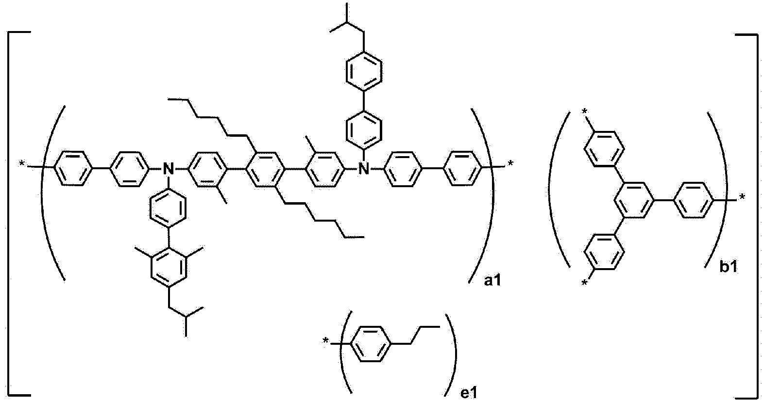


- An organic light emitting device comprising:a first electrode;a second electrode; andan organic material layer having one or more layers provided between the first electrode and the second electrode,wherein one or more layers of the organic material layer comprise the polymer of any one of claims 1 to 7.
- The organic light emitting device of claim 11,
wherein the organic material layer comprising the polymer is a hole injection layer, a hole transport layer, or a layer which simultaneously injects and transports holes.
Applications Claiming Priority (2)
| Application Number | Priority Date | Filing Date | Title |
|---|---|---|---|
| KR20210180872 | 2021-12-16 | ||
| PCT/KR2022/020384 WO2023113475A1 (en) | 2021-12-16 | 2022-12-14 | Polymer and organic light-emitting device using same |
Publications (1)
| Publication Number | Publication Date |
|---|---|
| EP4368652A1 true EP4368652A1 (en) | 2024-05-15 |
Family
ID=86773062
Family Applications (1)
| Application Number | Title | Priority Date | Filing Date |
|---|---|---|---|
| EP22907942.1A Pending EP4368652A1 (en) | 2021-12-16 | 2022-12-14 | Polymer and organic light-emitting device using same |
Country Status (5)
| Country | Link |
|---|---|
| EP (1) | EP4368652A1 (en) |
| JP (1) | JP2024528944A (en) |
| KR (1) | KR20230091804A (en) |
| CN (1) | CN117715953A (en) |
| WO (1) | WO2023113475A1 (en) |
Family Cites Families (9)
| Publication number | Priority date | Publication date | Assignee | Title |
|---|---|---|---|---|
| KR100578424B1 (en) | 2002-05-07 | 2006-05-11 | 주식회사 엘지화학 | New organic compounds for electroluminescence and organic electroluminescent devices using the same |
| US7351358B2 (en) | 2004-03-17 | 2008-04-01 | E.I. Du Pont De Nemours And Company | Water dispersible polypyrroles made with polymeric acid colloids for electronics applications |
| US8465848B2 (en) | 2006-12-29 | 2013-06-18 | E I Du Pont De Nemours And Company | Benzofluorenes for luminescent applications |
| CN104370686A (en) | 2009-09-03 | 2015-02-25 | E.I.内穆尔杜邦公司 | Deuterated Compounds For Electronic Applications |
| TW201204687A (en) * | 2010-06-17 | 2012-02-01 | Du Pont | Electroactive materials |
| US9954174B2 (en) * | 2015-05-06 | 2018-04-24 | E I Du Pont De Nemours And Company | Hole transport materials |
| JP2020107869A (en) * | 2018-12-28 | 2020-07-09 | 三星電子株式会社Samsung Electronics Co.,Ltd. | Organic electroluminescence element and method of manufacturing the same |
| JP2020105469A (en) * | 2018-12-28 | 2020-07-09 | 三星電子株式会社Samsung Electronics Co.,Ltd. | Polymer compound, and charge transport material, composition, organic layer and organic electroluminescent element that comprise the same |
| KR102489570B1 (en) * | 2020-03-27 | 2023-01-17 | 주식회사 엘지화학 | Novel polymer and organic light emitting device comprising the same |
-
2022
- 2022-12-14 EP EP22907942.1A patent/EP4368652A1/en active Pending
- 2022-12-14 JP JP2024506248A patent/JP2024528944A/en active Pending
- 2022-12-14 CN CN202280052488.5A patent/CN117715953A/en active Pending
- 2022-12-14 KR KR1020220175174A patent/KR20230091804A/en active Search and Examination
- 2022-12-14 WO PCT/KR2022/020384 patent/WO2023113475A1/en active Application Filing
Also Published As
| Publication number | Publication date |
|---|---|
| JP2024528944A (en) | 2024-08-01 |
| CN117715953A (en) | 2024-03-15 |
| KR20230091804A (en) | 2023-06-23 |
| WO2023113475A1 (en) | 2023-06-22 |
Similar Documents
| Publication | Publication Date | Title |
|---|---|---|
| EP3680261B1 (en) | Polymer, coating composition comprising same, and organic light emitting element using same | |
| KR20220045781A (en) | Polymer and organic light emitting device using the same | |
| EP4063427A1 (en) | Polymer and organic light-emitting diode using same | |
| EP4368652A1 (en) | Polymer and organic light-emitting device using same | |
| EP4400526A1 (en) | Polymer and organic light-emitting device using same | |
| EP4276129A1 (en) | Polymer and organic light-emitting device using same | |
| EP4357385A1 (en) | Polymer, and organic light-emitting element using same | |
| EP3960778A1 (en) | Polymer, coating composition comprising same, and organic light emitting device using same | |
| EP3702359B1 (en) | Compound, coating composition comprising same, organic light-emitting element using same, and manufacturing method therefor | |
| EP4063342A1 (en) | Fluorene-based compound, organic light-emitting device using same, and manufacturing method therefor | |
| EP4403554A1 (en) | Compound, coating composition comprising same, organic light-emitting device using same, and manufacturing method therefor | |
| KR20220168819A (en) | Polymer and organic light emitting device using the same | |
| KR20240123147A (en) | Polymer and organic light emitting device comprising the same | |
| KR20240123148A (en) | Polymer and organic light emitting device comprising the same | |
| KR20220168810A (en) | Polymer and organic light emitting device using the same | |
| KR20220138684A (en) | Polymer and organic light emitting device using the same | |
| KR20220138683A (en) | Polymer and organic light emitting device using the same | |
| KR20230017447A (en) | Polymer and organic light emitting device using the same | |
| KR20220138681A (en) | Polymer and organic light emitting device using the same | |
| KR20210091061A (en) | Polymer and organic light emitting device using the same | |
| KR20230014355A (en) | Polymer and organic light emitting device using the same | |
| KR20220168826A (en) | Polymer and organic light emitting device using the same | |
| KR20230014626A (en) | Polymer and organic light emitting device using the same | |
| KR20220018219A (en) | Polymer and organic light emitting device using the same | |
| KR20220058087A (en) | Polymer and organic light emitting device using the same |
Legal Events
| Date | Code | Title | Description |
|---|---|---|---|
| STAA | Information on the status of an ep patent application or granted ep patent |
Free format text: STATUS: THE INTERNATIONAL PUBLICATION HAS BEEN MADE |
|
| PUAI | Public reference made under article 153(3) epc to a published international application that has entered the european phase |
Free format text: ORIGINAL CODE: 0009012 |
|
| STAA | Information on the status of an ep patent application or granted ep patent |
Free format text: STATUS: REQUEST FOR EXAMINATION WAS MADE |
|
| 17P | Request for examination filed |
Effective date: 20240206 |
|
| AK | Designated contracting states |
Kind code of ref document: A1 Designated state(s): AL AT BE BG CH CY CZ DE DK EE ES FI FR GB GR HR HU IE IS IT LI LT LU LV MC ME MK MT NL NO PL PT RO RS SE SI SK SM TR |