EP4374058B1 - A nozzle cap for a fuel injection nozzle operable in a hydrogen internal combustion engine - Google Patents
A nozzle cap for a fuel injection nozzle operable in a hydrogen internal combustion engine Download PDFInfo
- Publication number
- EP4374058B1 EP4374058B1 EP21749162.0A EP21749162A EP4374058B1 EP 4374058 B1 EP4374058 B1 EP 4374058B1 EP 21749162 A EP21749162 A EP 21749162A EP 4374058 B1 EP4374058 B1 EP 4374058B1
- Authority
- EP
- European Patent Office
- Prior art keywords
- flow
- nozzle cap
- hydrogen
- exit surface
- outlet
- Prior art date
- Legal status (The legal status is an assumption and is not a legal conclusion. Google has not performed a legal analysis and makes no representation as to the accuracy of the status listed.)
- Active
Links
Images






Classifications
-
- F—MECHANICAL ENGINEERING; LIGHTING; HEATING; WEAPONS; BLASTING
- F02—COMBUSTION ENGINES; HOT-GAS OR COMBUSTION-PRODUCT ENGINE PLANTS
- F02M—SUPPLYING COMBUSTION ENGINES IN GENERAL WITH COMBUSTIBLE MIXTURES OR CONSTITUENTS THEREOF
- F02M21/00—Apparatus for supplying engines with non-liquid fuels, e.g. gaseous fuels stored in liquid form
- F02M21/02—Apparatus for supplying engines with non-liquid fuels, e.g. gaseous fuels stored in liquid form for gaseous fuels
- F02M21/0218—Details on the gaseous fuel supply system, e.g. tanks, valves, pipes, pumps, rails, injectors or mixers
- F02M21/0248—Injectors
- F02M21/0257—Details of the valve closing elements, e.g. valve seats, stems or arrangement of flow passages
- F02M21/026—Lift valves, i.e. stem operated valves
- F02M21/0263—Inwardly opening single or multi nozzle valves, e.g. needle valves
-
- F—MECHANICAL ENGINEERING; LIGHTING; HEATING; WEAPONS; BLASTING
- F02—COMBUSTION ENGINES; HOT-GAS OR COMBUSTION-PRODUCT ENGINE PLANTS
- F02M—SUPPLYING COMBUSTION ENGINES IN GENERAL WITH COMBUSTIBLE MIXTURES OR CONSTITUENTS THEREOF
- F02M21/00—Apparatus for supplying engines with non-liquid fuels, e.g. gaseous fuels stored in liquid form
- F02M21/02—Apparatus for supplying engines with non-liquid fuels, e.g. gaseous fuels stored in liquid form for gaseous fuels
- F02M21/0203—Apparatus for supplying engines with non-liquid fuels, e.g. gaseous fuels stored in liquid form for gaseous fuels characterised by the type of gaseous fuel
- F02M21/0206—Non-hydrocarbon fuels, e.g. hydrogen, ammonia or carbon monoxide
-
- F—MECHANICAL ENGINEERING; LIGHTING; HEATING; WEAPONS; BLASTING
- F02—COMBUSTION ENGINES; HOT-GAS OR COMBUSTION-PRODUCT ENGINE PLANTS
- F02M—SUPPLYING COMBUSTION ENGINES IN GENERAL WITH COMBUSTIBLE MIXTURES OR CONSTITUENTS THEREOF
- F02M21/00—Apparatus for supplying engines with non-liquid fuels, e.g. gaseous fuels stored in liquid form
- F02M21/02—Apparatus for supplying engines with non-liquid fuels, e.g. gaseous fuels stored in liquid form for gaseous fuels
- F02M21/0218—Details on the gaseous fuel supply system, e.g. tanks, valves, pipes, pumps, rails, injectors or mixers
- F02M21/0248—Injectors
- F02M21/0257—Details of the valve closing elements, e.g. valve seats, stems or arrangement of flow passages
- F02M21/026—Lift valves, i.e. stem operated valves
-
- F—MECHANICAL ENGINEERING; LIGHTING; HEATING; WEAPONS; BLASTING
- F02—COMBUSTION ENGINES; HOT-GAS OR COMBUSTION-PRODUCT ENGINE PLANTS
- F02M—SUPPLYING COMBUSTION ENGINES IN GENERAL WITH COMBUSTIBLE MIXTURES OR CONSTITUENTS THEREOF
- F02M21/00—Apparatus for supplying engines with non-liquid fuels, e.g. gaseous fuels stored in liquid form
- F02M21/02—Apparatus for supplying engines with non-liquid fuels, e.g. gaseous fuels stored in liquid form for gaseous fuels
- F02M21/0218—Details on the gaseous fuel supply system, e.g. tanks, valves, pipes, pumps, rails, injectors or mixers
- F02M21/0248—Injectors
- F02M21/0257—Details of the valve closing elements, e.g. valve seats, stems or arrangement of flow passages
- F02M21/026—Lift valves, i.e. stem operated valves
- F02M21/0269—Outwardly opening valves, e.g. poppet valves
-
- F—MECHANICAL ENGINEERING; LIGHTING; HEATING; WEAPONS; BLASTING
- F02—COMBUSTION ENGINES; HOT-GAS OR COMBUSTION-PRODUCT ENGINE PLANTS
- F02M—SUPPLYING COMBUSTION ENGINES IN GENERAL WITH COMBUSTIBLE MIXTURES OR CONSTITUENTS THEREOF
- F02M21/00—Apparatus for supplying engines with non-liquid fuels, e.g. gaseous fuels stored in liquid form
- F02M21/02—Apparatus for supplying engines with non-liquid fuels, e.g. gaseous fuels stored in liquid form for gaseous fuels
- F02M21/0218—Details on the gaseous fuel supply system, e.g. tanks, valves, pipes, pumps, rails, injectors or mixers
- F02M21/0248—Injectors
- F02M21/0275—Injectors for in-cylinder direct injection, e.g. injector combined with spark plug
-
- F—MECHANICAL ENGINEERING; LIGHTING; HEATING; WEAPONS; BLASTING
- F02—COMBUSTION ENGINES; HOT-GAS OR COMBUSTION-PRODUCT ENGINE PLANTS
- F02M—SUPPLYING COMBUSTION ENGINES IN GENERAL WITH COMBUSTIBLE MIXTURES OR CONSTITUENTS THEREOF
- F02M21/00—Apparatus for supplying engines with non-liquid fuels, e.g. gaseous fuels stored in liquid form
- F02M21/02—Apparatus for supplying engines with non-liquid fuels, e.g. gaseous fuels stored in liquid form for gaseous fuels
- F02M21/0218—Details on the gaseous fuel supply system, e.g. tanks, valves, pipes, pumps, rails, injectors or mixers
- F02M21/0248—Injectors
- F02M21/0278—Port fuel injectors for single or multipoint injection into the air intake system
-
- F—MECHANICAL ENGINEERING; LIGHTING; HEATING; WEAPONS; BLASTING
- F02—COMBUSTION ENGINES; HOT-GAS OR COMBUSTION-PRODUCT ENGINE PLANTS
- F02M—SUPPLYING COMBUSTION ENGINES IN GENERAL WITH COMBUSTIBLE MIXTURES OR CONSTITUENTS THEREOF
- F02M21/00—Apparatus for supplying engines with non-liquid fuels, e.g. gaseous fuels stored in liquid form
- F02M21/02—Apparatus for supplying engines with non-liquid fuels, e.g. gaseous fuels stored in liquid form for gaseous fuels
- F02M21/0218—Details on the gaseous fuel supply system, e.g. tanks, valves, pipes, pumps, rails, injectors or mixers
- F02M21/0248—Injectors
- F02M21/0281—Adapters, sockets or the like to mount injection valves onto engines; Fuel guiding passages between injectors and the air intake system or the combustion chamber
-
- F—MECHANICAL ENGINEERING; LIGHTING; HEATING; WEAPONS; BLASTING
- F02—COMBUSTION ENGINES; HOT-GAS OR COMBUSTION-PRODUCT ENGINE PLANTS
- F02M—SUPPLYING COMBUSTION ENGINES IN GENERAL WITH COMBUSTIBLE MIXTURES OR CONSTITUENTS THEREOF
- F02M61/00—Fuel-injectors not provided for in groups F02M39/00 - F02M57/00 or F02M67/00
- F02M61/16—Details not provided for in, or of interest apart from, the apparatus of groups F02M61/02 - F02M61/14
- F02M61/18—Injection nozzles, e.g. having valve seats; Details of valve member seated ends, not otherwise provided for
- F02M61/1806—Injection nozzles, e.g. having valve seats; Details of valve member seated ends, not otherwise provided for characterised by the arrangement of discharge orifices, e.g. orientation or size
-
- Y—GENERAL TAGGING OF NEW TECHNOLOGICAL DEVELOPMENTS; GENERAL TAGGING OF CROSS-SECTIONAL TECHNOLOGIES SPANNING OVER SEVERAL SECTIONS OF THE IPC; TECHNICAL SUBJECTS COVERED BY FORMER USPC CROSS-REFERENCE ART COLLECTIONS [XRACs] AND DIGESTS
- Y02—TECHNOLOGIES OR APPLICATIONS FOR MITIGATION OR ADAPTATION AGAINST CLIMATE CHANGE
- Y02T—CLIMATE CHANGE MITIGATION TECHNOLOGIES RELATED TO TRANSPORTATION
- Y02T10/00—Road transport of goods or passengers
- Y02T10/10—Internal combustion engine [ICE] based vehicles
- Y02T10/30—Use of alternative fuels, e.g. biofuels
Definitions
- the present disclosure relates to a nozzle cap for a fuel injection nozzle operable in a hydrogen internal combustion engine.
- the present disclosure also relates to a corresponding fuel injection nozzle, to a hydrogen internal combustion engine, and to vehicle.
- vehicle e.g. buses and construction equipment, as well as for marine applications, genset applications, and cars.
- a hydrogen injector for a hydrogen engine is typically run at critical conditions at which the hydrogen flow becomes sonic or even locally supersonic.
- One problem with this type of flow is difficulties to maintain the initial direction of the jet out of the injector nozzle.
- One commonly used hydrogen nozzle is a so called pintle-valve nozzle.
- An angle of the upper part of the pintle valve surface is a design-parameter which may determine the outgoing direction of the jet.
- a pintle-valve can be combined with a nozzle cap.
- the cap comprises one or several holes and the configuration of the holes is often used to determine the direction of the outgoing jet.
- US 2017321636 A1 and US 2017328310 A1 disclose hydrogen nozzles comprising nozzle caps.
- a particular problem with a hydrogen nozzle is that the nozzle cap hole exit area needs to be larger than conventional engine nozzles. This means that a major part of the nozzle cap side and bottom sides are open holes. It is therefore difficult to design the holes to direct the jets in a wanted direction, especially at sonic or even locally supersonic hydrogen flow. Further, this may lead to disturbing vortices in the cap volume. Such disturbing vortices may re-direct part of the flow in an un-favourable direction. Furthermore, the cap-volume as such may contain residual hydrogen-containing gases that may auto-ignite at an un-favourable timing.
- An object of the invention is to provide a nozzle cap for fuel injection nozzle that at least partly alleviates the deficiencies with the prior art.
- the object is achieved by a nozzle cap according to claim 1.
- a nozzle cap for a fuel injection nozzle operable in a hydrogen internal combustion engine.
- the nozzle cap comprising an inlet for receiving a flow of hydrogen controllable by an inlet valve arrangeable in the inlet. At least one outlet for providing an exit flow of hydrogen, and an internal bottom flow-guiding body arranged at a bottom side of the nozzle cap downstream of the inlet in a nozzle cap volume.
- the internal bottom flow-guiding body comprises a convex ridge protruding towards the inlet and comprises a flow-guiding surface for re-directing a flow of hydrogen from the inlet towards the outlet.
- the convex ridge is centralized in the bottom of the nozzle cap and is arranged to reach from side-to-side across the entire nozzle cap volume.
- the present invention is based on the realization that to minimize circular flow in the nozzle cap the internal structures and surfaces of the nozzle cap can be modified to lead the flow of hydrogen towards the outlet of the nozzle cap with reduced vortices in the inner volume of the nozzle cap.
- One advantageous inner structure is the internal bottom flow-guiding body which defines a flow-guiding surface that is in contact with the stream of hydrogen gas. This internal bottom flow-guiding body advantageously leads the hydrogen gas towards the outlet while at the same time reducing the dead-volume in the cap which reduces the amount of residual hydrogen that can remain in the nozzle cap.
- the hydrogen stream is guided towards the outlet such that hydrogen injection for the hydrogen internal combustion engine can be efficiently performed.
- the inlet valve arrangeable in the inlet of the nozzle cap may for example be a pintle valve that are per se known in the art, although other types or valves are conceivable.
- the outlet of the nozzle cap directs the hydrogen stream into, or towards a combustion chamber of the hydrogen internal combustion engine.
- the outlet may comprise a first exit surface and a second exit surface forming the outlet, wherein the shape of the first exit surface substantially follows the shape of the second exit surface, such that the exit flow of hydrogen from the outlet at the first exit surface is in substantially the same direction as the exit flow of hydrogen at the second exit surface.
- the surfaces of the outlet are adapted to further improve the guidance of the hydrogen stream.
- the exits surfaces are in this way intentionally shaped to control the exit direction of the hydrogen flow.
- the first and second exit surfaces may be considered hole-edge surfaces of the outlet. That the exit flow is in substantially the same direction should be interpreted as that the main flow is in the same direction or near the same direction where a small deviation is allowed.
- the nozzle cap may further comprise at least a first internal side flow-guiding body arranged at a side-wall surface of the nozzle cap and protruding inwards in a nozzle cap volume, for guiding the flow of hydrogen towards the at least one outlet.
- the at least one internal side flow-guiding body provides at least one additional flow-guiding surface that contributes to reducing vortices in the nozzle cap volume by assisting in leading the hydrogen flow towards the outlet.
- the first internal side flow-guiding body cooperates with the internal bottom flow-guiding body to lead the hydrogen flow towards the outlet.
- the outlet may comprise a first exit surface and a second exit surface forming the outlet, wherein the shape of the at least one first internal side flow-guiding body substantially follows a shape of the flow-guiding surface of the internal bottom flow-guiding body, such that the exit flow of hydrogen from the outlet at the first exit surface is in substantially the same direction as the exit flow of hydrogen at the second exit surface. That the exit flow is in substantially the same direction should be interpreted as that the main flow is in the same direction or near the same direction where a small deviation is allowed.
- the first internal side flow-guiding body and the internal flow-guiding body advantageously cooperates to better guide the hydrogen stream towards the outlet.
- the outlet may comprise a first exit surface and a second exit surface, wherein the flow-guiding surface of the internal bottom flow-guiding body is arranged next to the second exit surface, the flow-guiding surface and the second exit surface are configured to co-operatively direct the exit flow of hydrogen at the second exit surface in the same direction as the exit flow of hydrogen at the first exit surface.
- the nozzle cap is further improved to guide the hydrogen flow towards the outlet. That the internal bottom flow-guiding body is arranged next to the second exit surface means that they are directly neighbouring, i.e. being adjacent to each other.
- the flow-guiding surface of the internal bottom flow-guiding body and the second exit surface may form a single seamless flow-guiding surface.
- the internal bottom flow-guiding body may be configured to redirect a flow of hydrogen towards to two opposite sides of the nozzle cap.
- the opposite sides may be on two sides of a centre axis of the nozzle cap. This is advantageous if, for example, the nozzle cap comprises outlets on the two opposite sides.
- the nozzle cap may comprise two outlets arranged on opposite sides of the internal bottom flow-guiding body, wherein the internal flow-guiding bodies are configured to redirect a flow of hydrogen from the inlet towards the two outlets.
- the internal bottom flow-guiding body may be centralized in the bottom of the nozzle cap.
- the internal bottom flow-guiding body may be arranged off-set from a centre of the bottom of the nozzle cap.
- an offset arrangement may be used in some implementations, e.g. with only one outlet to reduce flow to a side not having an outlet.
- a centralized location may be advantageous when it is desirable to direct equal amount so flow to the different sides of the nozzle cap.
- the internal bottom flow-guiding body may be shaped to substantially fill the side of the nozzle cap opposite the outlet.
- the dead-volume in the nozzle cap is advantageously reduced which leads to reduced amount of residual hydrogen that can remain in the nozzle cap.
- the number of outlets is more than two, wherein the internal bottom flow-guiding body comprising a set of flow-guiding surfaces for re-directing a flow of hydrogen towards each of the outlets.
- the internal bottom flow-guiding body may advantageously be designed in correspondence with the number of outlets, still providing improved flow of hydrogen through the nozzle cap.
- the nozzle cap may have different outer shapes depending on the implementations at hand.
- the internal bottom flow-guiding body may have a convex outer shape.
- the internal bottom flow-guiding body comprises flow-guiding elements protruding from the upper ridge of the internal bottom flow-guiding body for further providing further adjustments of the hydrogen-flow in the nozzle cap.
- the nozzle cap is further improved to guide the hydrogen flow towards the outlet.
- a hydrogen internal combustion engine comprising a fuel injection nozzle according to the second aspect.
- first exit surface and a second exit surface forming the outlet together form a conical outlet.
- the flow-guiding surface 112 of the internal bottom flow-guiding body 109 is arranged next to the second exit surface 116.
- the flow-guiding surface 112 and the second exit surface form a seamless flow-guiding surface extending along the internal bottom flow-guiding body 109 all the way to the outlet 108.
- the flow-guiding surface 112 and the second exit surface 116 are configured to co-operatively direct the exit flow of hydrogen at the second exit surface in the same direction as the exit flow of hydrogen at the first exit surface 116.
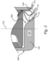
- Fig. 3 conceptually illustrates a comparative example not covered by the claims. This embodiment may be primarily intended for a single-hole cap with a main hole-direction presenting a certain angle related to the injector centre axis direction.
- the nozzle cap 300 illustrated in fig. 3 differs from that shown in fig. 2A-B in that the internal bottom flow-guiding body 309 is shaped to substantially fill the side 140 of the nozzle cap opposite the outlet 108. In other words, instead of leaving an open volume on the side of the internal bottom flow-guiding body 109 where there is no outlet, the internal bottom flow-guiding body 309 fills up that volume. This significantly reduces the amount of residual hydrogen that can remain in the nozzle cap 300.
- the first internal side flow-guiding body 518 is shaped with a convex outer surface to allow for receiving the flow form the inlet and guide the flow over surface of the guiding the flow along the internal flow-guiding body 518, with assistance from the oppositely arranged internal bottom flow-guiding body 509 with respect to the outlets 508a-b.
- the internal bottom flow-guiding body comprising a set of flow-guiding surfaces for re-directing a flow of hydrogen towards each of the outlets.
- the internal bottom flow-guiding body is advantageous to have the internal bottom flow-guiding body to be shaped to fill-out the volume between two outlets in the nozzle cap volume.
- the internal bottom flow-guiding body reaches across the entire inner volume of the nozzle cap, from side-to-side, but leaves the openings open.
- the internal bottom flow-guiding body 509, 109 is centralized in the bottom of the nozzle cap.
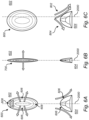
- Figs. 6A-F conceptually illustrates different configurations for internal bottom flow-guiding bodies.
- example height curves and shapes of the internal bottom flow-guiding bodies are illustrated.
- the shape of the internal bottom flow-guiding bodies is generally configured to assist the flow of hydrogen to efficiently reach the outlet of the nozzle cap in a preferred direction.
- Fig. 6A is a top view 602 and a side view 604 of an internal bottom flow-guiding body 600 according to the claims and having a convex outer shape.
- the flow-guiding surfaces 606 have a convex shape and are configured to direct flow of hydrogen from the inlet to the outlet as described herein.
- the flow-guiding surfaces 606 have a relatively shallow slope. Further, at side portions 608 a passage is formed between the internal bottom flow-guiding body 600 and the inlet valve pintle (not shown in fig. 6A ).
- the axis 2000 indicates the centre of the nozzle cap, thus, the internal bottom flow-guiding body 600 is here indicated as centralized in the nozzle cap.
- Fig. 6B is a top view 602 and a side view 604 of an internal bottom flow-guiding body 700 according to the claims and having a convex outer shape but with a narrower side-ways extension compare to the internal bottom flow-guiding body 600 shown in fig. 6A .
- the internal bottom flow-guiding body 700 is configured as barrier type structures that allows minimal cross-flow between the sides of the internal bottom flow-guiding body 700.
- Fig. 6E is a top view 602 and a side view 604 of an internal bottom flow-guiding body 1000 not covered by the claims, adapted to fill out one side of the nozzle cap opposite the outlet.
- a flow-guiding surface 1006 adapted to guide a flow of hydrogen towards an outlet.
- the other side of the internal bottom flow-guiding body 1000 fills out the volume of the nozzle cap on that side. Thus, very little flow is directed towards the fill out side of the nozzle cap.
- Fig. 6F is a top view 602 and a side view 604 of an internal bottom flow-guiding body 1100 not covered by the claims, having a concave outer shape.
- the flow-guiding surfaces 1106 having a concave shape are advantageous for directing the flow of hydrogen towards the centre of the outlets 108, in other words, the concave shape of the flow-guiding surfaces 1106 provides for converging the flow towards the centre of the outlets 108.
- Fig. 7 conceptually illustrates a perspective cross-section of a nozzle cap 1300 according to embodiments of the invention.
- the internal bottom flow-guiding body 1309 comprises a flow-guiding element 1312 protruding from the upper ridge 1314 of the internal bottom flow-guiding body 1309. This provides for adjusting of the hydrogen-flow in the nozzle cap towards preferred directions.
- the flow-guiding element 1312 is specifically adapted to guide the minor flow going from the valve-seat in the region between the nozzle cap outlets 108a,b such that the flow in this location between the outlets is better directed towards the outlets 108a,b.
- the flow-guiding element 1312 is thus designed to redirect downwards going flow reaching the bottom flow-guiding body 1309 at locations between the outlets 108a, 108b.
- the nozzle caps are preferably made of steel.
Landscapes
- Engineering & Computer Science (AREA)
- Chemical & Material Sciences (AREA)
- Combustion & Propulsion (AREA)
- Mechanical Engineering (AREA)
- General Engineering & Computer Science (AREA)
- Chemical Kinetics & Catalysis (AREA)
- General Chemical & Material Sciences (AREA)
- Oil, Petroleum & Natural Gas (AREA)
- Nozzles (AREA)
- Fuel Cell (AREA)
Description
- The present disclosure relates to a nozzle cap for a fuel injection nozzle operable in a hydrogen internal combustion engine. The present disclosure also relates to a corresponding fuel injection nozzle, to a hydrogen internal combustion engine, and to vehicle. Although the invention will be described in relation to a vehicle in the form of a truck, the invention can also be efficiently incorporated in other vehicles types such as e.g. buses and construction equipment, as well as for marine applications, genset applications, and cars.
- A hydrogen injector for a hydrogen engine is typically run at critical conditions at which the hydrogen flow becomes sonic or even locally supersonic. One problem with this type of flow is difficulties to maintain the initial direction of the jet out of the injector nozzle.
- One commonly used hydrogen nozzle is a so called pintle-valve nozzle. An angle of the upper part of the pintle valve surface is a design-parameter which may determine the outgoing direction of the jet. In order to further control the outgoing direction of the jet, a pintle-valve can be combined with a nozzle cap. The cap comprises one or several holes and the configuration of the holes is often used to determine the direction of the outgoing jet. For example,
US 2017321636 A1 andUS 2017328310 A1 disclose hydrogen nozzles comprising nozzle caps. - A particular problem with a hydrogen nozzle is that the nozzle cap hole exit area needs to be larger than conventional engine nozzles. This means that a major part of the nozzle cap side and bottom sides are open holes. It is therefore difficult to design the holes to direct the jets in a wanted direction, especially at sonic or even locally supersonic hydrogen flow. Further, this may lead to disturbing vortices in the cap volume. Such disturbing vortices may re-direct part of the flow in an un-favourable direction. Furthermore, the cap-volume as such may contain residual hydrogen-containing gases that may auto-ignite at an un-favourable timing.
- Accordingly, there is room for improvements with regards to hydrogen flow guidance in hydrogen nozzles.
- An object of the invention is to provide a nozzle cap for fuel injection nozzle that at least partly alleviates the deficiencies with the prior art.
- According to a first aspect of the invention, the object is achieved by a nozzle cap according to
claim 1. - According to the first aspect of the invention, there is provided a nozzle cap for a fuel injection nozzle operable in a hydrogen internal combustion engine. The nozzle cap comprising an inlet for receiving a flow of hydrogen controllable by an inlet valve arrangeable in the inlet. At least one outlet for providing an exit flow of hydrogen, and an internal bottom flow-guiding body arranged at a bottom side of the nozzle cap downstream of the inlet in a nozzle cap volume. The internal bottom flow-guiding body comprises a convex ridge protruding towards the inlet and comprises a flow-guiding surface for re-directing a flow of hydrogen from the inlet towards the outlet. The convex ridge is centralized in the bottom of the nozzle cap and is arranged to reach from side-to-side across the entire nozzle cap volume.
- The present invention is based on the realization that to minimize circular flow in the nozzle cap the internal structures and surfaces of the nozzle cap can be modified to lead the flow of hydrogen towards the outlet of the nozzle cap with reduced vortices in the inner volume of the nozzle cap. One advantageous inner structure is the internal bottom flow-guiding body which defines a flow-guiding surface that is in contact with the stream of hydrogen gas. This internal bottom flow-guiding body advantageously leads the hydrogen gas towards the outlet while at the same time reducing the dead-volume in the cap which reduces the amount of residual hydrogen that can remain in the nozzle cap.
- Thus, by the provision of the herein proposed nozzle cap the hydrogen stream is guided towards the outlet such that hydrogen injection for the hydrogen internal combustion engine can be efficiently performed.
- The inlet valve arrangeable in the inlet of the nozzle cap may for example be a pintle valve that are per se known in the art, although other types or valves are conceivable.
- The outlet of the nozzle cap directs the hydrogen stream into, or towards a combustion chamber of the hydrogen internal combustion engine.
- In one embodiment, the outlet may comprise a first exit surface and a second exit surface forming the outlet, wherein the shape of the first exit surface substantially follows the shape of the second exit surface, such that the exit flow of hydrogen from the outlet at the first exit surface is in substantially the same direction as the exit flow of hydrogen at the second exit surface. Thus, the surfaces of the outlet are adapted to further improve the guidance of the hydrogen stream. The exits surfaces are in this way intentionally shaped to control the exit direction of the hydrogen flow. The first and second exit surfaces may be considered hole-edge surfaces of the outlet. That the exit flow is in substantially the same direction should be interpreted as that the main flow is in the same direction or near the same direction where a small deviation is allowed.
- In one embodiment, the nozzle cap may further comprise at least a first internal side flow-guiding body arranged at a side-wall surface of the nozzle cap and protruding inwards in a nozzle cap volume, for guiding the flow of hydrogen towards the at least one outlet. Hereby, guiding of the hydrogen flow is even further improved. The at least one internal side flow-guiding body provides at least one additional flow-guiding surface that contributes to reducing vortices in the nozzle cap volume by assisting in leading the hydrogen flow towards the outlet. The first internal side flow-guiding body cooperates with the internal bottom flow-guiding body to lead the hydrogen flow towards the outlet.
- In one embodiment, the outlet may comprise a first exit surface and a second exit surface forming the outlet, wherein the shape of the at least one first internal side flow-guiding body substantially follows a shape of the flow-guiding surface of the internal bottom flow-guiding body, such that the exit flow of hydrogen from the outlet at the first exit surface is in substantially the same direction as the exit flow of hydrogen at the second exit surface. That the exit flow is in substantially the same direction should be interpreted as that the main flow is in the same direction or near the same direction where a small deviation is allowed. Hereby, the first internal side flow-guiding body and the internal flow-guiding body advantageously cooperates to better guide the hydrogen stream towards the outlet.
- The shape of the outlet along the flow direction may be that the first and second exit surfaces are parallel. However, other outlet shapes or configurations are possible. For example, in one embodiment, the outlet comprises a first exit surface and a second exit surface forming the outlet, wherein the first exit surface and a second exit surface together form a conical outlet.
- In one embodiment, the outlet may comprise a first exit surface and a second exit surface, wherein the flow-guiding surface of the internal bottom flow-guiding body is arranged next to the second exit surface, the flow-guiding surface and the second exit surface are configured to co-operatively direct the exit flow of hydrogen at the second exit surface in the same direction as the exit flow of hydrogen at the first exit surface. Hereby, the nozzle cap is further improved to guide the hydrogen flow towards the outlet. That the internal bottom flow-guiding body is arranged next to the second exit surface means that they are directly neighbouring, i.e. being adjacent to each other. The flow-guiding surface of the internal bottom flow-guiding body and the second exit surface may form a single seamless flow-guiding surface.
- In one embodiment, the internal bottom flow-guiding body may be configured to redirect a flow of hydrogen towards to two opposite sides of the nozzle cap. The opposite sides may be on two sides of a centre axis of the nozzle cap. This is advantageous if, for example, the nozzle cap comprises outlets on the two opposite sides.
- In one embodiment, the nozzle cap may comprise two outlets arranged on opposite sides of the internal bottom flow-guiding body, wherein the internal flow-guiding bodies are configured to redirect a flow of hydrogen from the inlet towards the two outlets.
- In embodiments, the internal bottom flow-guiding body may be centralized in the bottom of the nozzle cap.
- In other embodiments, the internal bottom flow-guiding body may be arranged off-set from a centre of the bottom of the nozzle cap.
- Different offsets and locations of the internal bottom flow-guiding body are advantageous depending on specific implementations at hand. For example, an offset arrangement may be used in some implementations, e.g. with only one outlet to reduce flow to a side not having an outlet. A centralized location may be advantageous when it is desirable to direct equal amount so flow to the different sides of the nozzle cap.
- In one embodiment, the internal bottom flow-guiding body may be shaped to substantially fill the side of the nozzle cap opposite the outlet. Hereby, the dead-volume in the nozzle cap is advantageously reduced which leads to reduced amount of residual hydrogen that can remain in the nozzle cap.
- In one embodiment, the number of outlets is more than two, wherein the internal bottom flow-guiding body comprising a set of flow-guiding surfaces for re-directing a flow of hydrogen towards each of the outlets. Thus, the internal bottom flow-guiding body may advantageously be designed in correspondence with the number of outlets, still providing improved flow of hydrogen through the nozzle cap.
- The nozzle cap may have different outer shapes depending on the implementations at hand.
- For example, in one embodiment, the internal bottom flow-guiding body may have a convex outer shape.
- In another embodiment, the internal bottom flow-guiding body may have a concave outer shape.
- In one embodiment, the internal bottom flow-guiding body comprises flow-guiding elements protruding from the upper ridge of the internal bottom flow-guiding body for further providing further adjustments of the hydrogen-flow in the nozzle cap. Hereby, the nozzle cap is further improved to guide the hydrogen flow towards the outlet.
- According to a second aspect of the invention, there is provided a fuel injection nozzle comprising an inlet valve and a nozzle cap according to any one of the herein disclosed embodiments.
- Effects and features of the second aspect of the invention are largely analogous to those described above in connection with the first aspect.
- According to a third aspect of the invention, there is provided a hydrogen internal combustion engine comprising a fuel injection nozzle according to the second aspect.
- According to a fourth aspect of the invention, there is provided a vehicle comprising a fuel injection nozzle according to the second aspect or a hydrogen internal combustion engine according to the third aspect.
- Effects and features of the third and fourth, aspects are largely analogous to those described above in relation to the first aspect and the second aspect.
- Further features of, and advantages will become apparent when studying the appended claims and the following description. The skilled person will realize that different features may be combined to create embodiments other than those described in the following, without departing from the scope of the present disclosure.
- With reference to the appended drawings, below follows a more detailed description of embodiments of the invention cited as examples.
- In the drawings:
-
Fig. 1 is a vehicle in the form a truck according to example embodiments of the invention; -
Fig. 2A is a perspective cross-sectional view including a nozzle cap according to example embodiments of the invention; -
Fig. 2B is a cross-sectional side-view of the nozzle cap and valve illustrated infig. 2A ; -
Fig. 3 is a cross-sectional side-view including a nozzle cap according to a comparative example not covered by the claims; -
Fig. 4A is a perspective cross-sectional view including a nozzle cap according to example embodiments of the invention; -
Fig. 4B is a cross-sectional side view of the nozzle cap and valve illustrated infig. 4A ; -
Fig. 5 is a cross-sectional side view including a nozzle cap according to example embodiments of the invention; -
Figs. 6A-6F conceptually illustrates different types of internal bottom flow-guiding bodies ; and -
Fig. 7 is a perspective cross-sectional view including a nozzle cap according to example embodiments of the invention. - The present invention will now be described more fully hereinafter with reference to the accompanying drawings, in which exemplary embodiments of the invention are shown. The invention may, however, be embodied in many different forms and should not be construed as limited to the embodiments set forth herein; rather, these embodiments are provided for thoroughness and completeness. The skilled person will recognize that many changes and modifications may be made within the scope of the appended claims. Like reference character refer to like elements throughout the description.
-
Fig. 1 illustrates a vehicle in the form of atruck 1 comprising anengine 2 such as for example an internal combustion engine. The internal combustion engine is a hydrogen engine. Thetruck 1 may be a hybrid electric vehicle. The hydrogeninternal combustion engine 2 oftruck 1 further comprises a fuel injection nozzle with a nozzle cap as disclosed herein. -
Fig. 2A is a perspective cross-sectional view of anozzle cap 100 for afuel injection nozzle 4 that, when in use, is operable in a hydrogeninternal combustion engine 2.Fig. 2B is a cross-section of thenozzle cap 100 and valve shown infig. 2A . Thenozzle cap 100 comprises aninlet 104 for receiving a flow of hydrogen. The flow of hydrogen is provided from storage of hydrogen that is typically pressurised. The flow of hydrogen through theinlet 104 is controllable by aninlet valve 106 arrangeable in theinlet 104. When thepintle 107 of thevalve 106 is in an upper position, theinlet 104 is closed and hydrogen is not allowed to enter thenozzle cap volume 111. In the lower position shown infigs 2A-B , theinlet 104 is open and hydrogen is allowed to enter the nozzle cap volume 11. - The
nozzle cap 100 further comprises at least oneoutlet 108 for providing an exit flow of hydrogen. An internal bottom flow-guidingbody 109 is arranged at abottom side 110 of thenozzle cap 100 downstream of theinlet 104 in thenozzle cap volume 111, e.g. opposite theinlet 109. The internal bottom flow-guidingbody 109 is shaped to protrude towards theinlet 104 and comprises a flow-guidingsurface 112 for re-directing a flow of hydrogen received from theinlet 104 towards theoutlet 108. - The hydrogen flow enters through the
inlet 104 and is initially guided by the flow-guidingsurface 123 of thevalve 108 and thevalve seat 124 before it enters thenozzle cap volume 111. If the internal bottom flow-guidingbody 109 was not present, vortices are created inside the cap and suboptimal flow of hydrogen towards theoutlet 108 is obtained. However, as provided by embodiments herein, the internal bottom flow-guidingbody 109 provides improved hydrogen flow guidance towards theoutlet 108. - The internal bottom flow-guiding
body 109 extends along anaxis 122 from thebottom side 110 towards the side of theinlet 104. The flow-guidingsurface 112 of the internal bottom flow-guidingbody 109 ensures that the flow of hydrogen follows its shape and is guided towards theoutlet 104. - The internal bottom flow-guiding
body 109 extends relatively close to thevalve 108 which advantageously reduces cross-flow of hydrogen across thecentre 122 of the internal bottom flow-guidingbody 109 and here also thenozzle cap 100 which further improves the guidance of the hydrogen flow. Further, the size of the internal bottom flow-guidingbody 109 is relatively large so that to fill-up a large portion of thenozzle cap volume 111. This reduces the risk for residual hydrogen to remain in thenozzle cap volume 106. Generally, the larger the size the better, however the size should not compromise the ability for the internal bottom flow-guidingbody 109 to guide the hydrogen flow towards theoutlet 108. Infig. 2A-B , the internal bottom flow-guiding body is centralized in thenozzle cap 100. - Further, a flow-guiding
surface 128 adjacent to thevalve seat 124 is shaped to guide flow towards theoutlet 108. The flow-guidingsurface 128 is adjacent to thevalve seat 124 so that a continuous flow-guiding surface is formed from the flow-guidingsurface 128 and thevalve seat 124. - The
surfaces outlet 108. For example, theoutlet 108 comprises afirst exit surface 114 and asecond exit surface 116 forming theoutlet 108. Thesesurfaces outlet 108. In order to provide an efficient flow through theoutlet 108, the shape of the first,upper exit surface 114, substantially follows the shape of the second,lower exit surface 116. In this way, the exit flow of hydrogen from theoutlet 108 at thefirst exit surface 114 is in substantially the same direction as the exit flow of hydrogen at thesecond exit surface 116. Thus, the shape of the flow-guidingsurface 112 and the exit surfaces 112 and 114 may be different depending on the relative locations of theoutlet 108 and theinlet 104 but are adapted to guide the hydrogen flow towards theoutlet 108. Infig. 2A , the internal bottom flow-guidingbody 109 has a convex outer shape, thus forming a convex ridge in the nozzle cap. The cross-sectional shape of the flow-guidingsurface 112 of the internal bottom flow-guidingbody 109 and thesecond exit surface 116 may be curved in two directions resembling an S-shape. - The
valve seat 124, the flow-guidingsurface 128, and thefirst exit surface 114 preferably form a continuous, smooth, flow-guiding surface. Similarly, the flow-guidingsurface 112 and thesecond exit surface 116 preferably form a continuous, smooth, flow-guiding surface. The flow-guidingsurface 128 of thecap wall 129 and the flow-guidingsurface 112 of the bottom flow-guiding body are smoothly connected through the hole edge surfaces 114 and 116. - It is also conceivable that the first exit surface and a second exit surface forming the outlet together form a conical outlet.
- The flow-guiding
surface 112 of the internal bottom flow-guidingbody 109 is arranged next to thesecond exit surface 116. Preferably, the flow-guidingsurface 112 and the second exit surface form a seamless flow-guiding surface extending along the internal bottom flow-guidingbody 109 all the way to theoutlet 108. The flow-guidingsurface 112 and thesecond exit surface 116 are configured to co-operatively direct the exit flow of hydrogen at the second exit surface in the same direction as the exit flow of hydrogen at thefirst exit surface 116. -
Fig. 3 conceptually illustrates a comparative example not covered by the claims. This embodiment may be primarily intended for a single-hole cap with a main hole-direction presenting a certain angle related to the injector centre axis direction. Thenozzle cap 300 illustrated infig. 3 differs from that shown infig. 2A-B in that the internal bottom flow-guidingbody 309 is shaped to substantially fill theside 140 of the nozzle cap opposite theoutlet 108. In other words, instead of leaving an open volume on the side of the internal bottom flow-guidingbody 109 where there is no outlet, the internal bottom flow-guidingbody 309 fills up that volume. This significantly reduces the amount of residual hydrogen that can remain in thenozzle cap 300. - The number of outlets of the nozzle cap may be more than one. Turning to
fig. 4A-B , there is shown anozzle cap 400 having twooutlets 108a-b.Fig. 4A is a perspective cross-sectional view of thenozzle cap 400 andfig. 4B is a cross-section of thenozzle cap 400. The internal bottom flow-guidingbody 409 is configured to redirect a flow of hydrogen towards to two opposite sides of thenozzle cap 400, where the two outlets are located. Thus, the internal bottom flow-guidingbody 409 comprises two opposite flow-guidingsurfaces 112a-b. A first flow-guidingsurface 112a is configured to guide hydrogen flow towards afirst outlet 108a and second flow-guidingsurface 112b is configured to guide hydrogen flow towards asecond outlet 108b. -
Fig. 5 conceptually illustrates a further embodiment of a nozzle cap. Here, thenozzle cap 500 comprises an internal bottom flow-guidingbody 509 as discussed above with reference to preceding drawings, and twooutlets 508a-b. Further, thenozzle cap 500 comprises at least a first internal side flow-guidingbody 518 arranged at a side-wall 520 of thenozzle cap 500 and protruding inwards in anozzle cap volume 506, for guiding the flow of hydrogen towards theoutlets 508a-b. Thus, theinternal bodies outer surfaces 510a-b, and 521a-b that are in contact with the hydrogen flow and that are cooperatively configured to lead the flow of hydrogen towards the outlets to reduce vortices in thecap volume 506. - The first internal side flow-guiding
body 518 is shaped with a convex outer surface to allow for receiving the flow form the inlet and guide the flow over surface of the guiding the flow along the internal flow-guidingbody 518, with assistance from the oppositely arranged internal bottom flow-guidingbody 509 with respect to theoutlets 508a-b. - Preferably, a shape of a surface portion 525 of the at least one first internal side flow-guiding
body 521a-b substantially follows a shape of the flow-guidingsurface 510a-b of the internal bottom flow-guiding body, such that the exit flow of hydrogen from the outlet at afirst exit surface second exit surface surface portion 525b of the internal side flow-guidingbody 521b adjacent to thesecond exit surface 514b is substantially similar to the shape of the internal bottom flow-guidingbody 509 in surface portions opposite thesurface portion 525b. Similarly, at theother outlet 108a, the shape of thesurface portion 525a of the internal side flow-guidingbody 521a adjacent to thesecond exit surface 514a is substantially similar to the shape of the internal bottom flow-guidingbody 509 in surface portions opposite thesurface portion 525a. - Generally, the internal flow-guiding
bodies outlets 508a-b. - In case the number of outlets is more than two, the internal bottom flow-guiding body comprising a set of flow-guiding surfaces for re-directing a flow of hydrogen towards each of the outlets.
- For each of the embodiments discussed with respect to
figs. 4A, 4B , andfig. 5 , is advantageous to have the internal bottom flow-guiding body to be shaped to fill-out the volume between two outlets in the nozzle cap volume. Thus, the internal bottom flow-guiding body reaches across the entire inner volume of the nozzle cap, from side-to-side, but leaves the openings open. Further, the internal bottom flow-guidingbody -
Figs. 6A-F conceptually illustrates different configurations for internal bottom flow-guiding bodies. Infigs 6A-F example height curves and shapes of the internal bottom flow-guiding bodies are illustrated. However, these are only examples, and variations are possible and within the scope of the present invention. The shape of the internal bottom flow-guiding bodies is generally configured to assist the flow of hydrogen to efficiently reach the outlet of the nozzle cap in a preferred direction. -
Fig. 6A is atop view 602 and aside view 604 of an internal bottom flow-guidingbody 600 according to the claims and having a convex outer shape. Thus, the flow-guidingsurfaces 606 have a convex shape and are configured to direct flow of hydrogen from the inlet to the outlet as described herein. - Here, the flow-guiding
surfaces 606 have a relatively shallow slope. Further, at side portions 608 a passage is formed between the internal bottom flow-guidingbody 600 and the inlet valve pintle (not shown infig. 6A ). Theaxis 2000 indicates the centre of the nozzle cap, thus, the internal bottom flow-guidingbody 600 is here indicated as centralized in the nozzle cap. -
Fig. 6B is atop view 602 and aside view 604 of an internal bottom flow-guidingbody 700 according to the claims and having a convex outer shape but with a narrower side-ways extension compare to the internal bottom flow-guidingbody 600 shown infig. 6A . The internal bottom flow-guidingbody 700 is configured as barrier type structures that allows minimal cross-flow between the sides of the internal bottom flow-guidingbody 700. -
Fig. 6C is atop view 602 and aside view 604 of an internal bottom flow-guidingbody 800 not covered by the claims, having a convex outer shape similar to the internal bottom flow-guidingbody 600 shown infig. 6A . However, the convex ridge of the internal bottom flow-guidingbody 800 is arranged off-set from acentre 2000 of the bottom of the nozzle cap. Thus, the internal bottom flow-guidingbody 800 is located such that more of the hydrogen stream is directed towards afirst side 802 of the internal bottom flow-guidingbody 800 than towards asecond side 804. In other words, the off-centre location of the internal bottom flow-guidingbody 800 favours direction the hydrogen flow towards thefirst side 802. -
Fig. 6D is atop view 602 and aside view 604 of an internal bottom flow-guidingbody 900 according to the claims and having a convex outer shape. A difference between the internal bottom flow-guidingbody 900 and the internal bottom flow-guidingbody 600 is that the slopes of the flow-guidingsurfaces 906 are steeper than the flow-guidingsurfaces 606 of the internal bottom flow-guidingbody 600. The steeper slope leads to asmaller passage 908 which advantageously reduces the cross-flow at across thecentre 2000 of the nozzle cap. -
Fig. 6E is atop view 602 and aside view 604 of an internal bottom flow-guidingbody 1000 not covered by the claims, adapted to fill out one side of the nozzle cap opposite the outlet. Thus, on one side of the internal bottom flow-guidingbody 1000 there is a flow-guidingsurface 1006 adapted to guide a flow of hydrogen towards an outlet. The other side of the internal bottom flow-guidingbody 1000 fills out the volume of the nozzle cap on that side. Thus, very little flow is directed towards the fill out side of the nozzle cap. -
Fig. 6F is atop view 602 and aside view 604 of an internal bottom flow-guidingbody 1100 not covered by the claims, having a concave outer shape. The flow-guidingsurfaces 1106 having a concave shape are advantageous for directing the flow of hydrogen towards the centre of theoutlets 108, in other words, the concave shape of the flow-guidingsurfaces 1106 provides for converging the flow towards the centre of theoutlets 108. -
Fig. 7 conceptually illustrates a perspective cross-section of anozzle cap 1300 according to embodiments of the invention. Here, the internal bottom flow-guidingbody 1309 comprises a flow-guidingelement 1312 protruding from theupper ridge 1314 of the internal bottom flow-guidingbody 1309. This provides for adjusting of the hydrogen-flow in the nozzle cap towards preferred directions. The flow-guidingelement 1312 is specifically adapted to guide the minor flow going from the valve-seat in the region between thenozzle cap outlets 108a,b such that the flow in this location between the outlets is better directed towards theoutlets 108a,b. The flow-guidingelement 1312 is thus designed to redirect downwards going flow reaching the bottom flow-guidingbody 1309 at locations between theoutlets - Although other possibilities are conceivable, the nozzle caps are preferably made of steel.
- Even though the invention has been described with reference to specific exemplifying embodiments thereof, many different alterations, modifications and the like will become apparent for those skilled in the art. Accordingly, it is to be understood that the present invention is not limited to the embodiments described above and illustrated in the drawings; rather, the skilled person will recognize that many changes and modifications may be made within the scope of the appended claims.
Claims (15)
- A nozzle cap (100) for a fuel injection nozzle operable in a hydrogen internal combustion engine (2), the nozzle cap comprising:an inlet (104) for receiving a flow of hydrogen controllable by an inlet valve (106) arrangeable in the inlet,at least one outlet (108) for providing an exit flow of hydrogen, andan internal bottom flow-guiding body (109) arranged at a bottom side (110) of the nozzle cap downstream of the inlet in a nozzle cap volume (111), the internal bottom flow-guiding body comprising a convex ridge protruding towards the inlet and comprises a flow-guiding surface (112) for re-directing a flow of hydrogen from the inlet towards the outlet,characterized in thatthe convex ridge is centralized in the bottom of the nozzle cap and is arranged to reach from side-to-side across the entire nozzle cap volume (111).
- The nozzle cap according to claim 1, wherein the outlet comprises a first exit surface (114) and a second exit surface (116) forming the outlet, wherein the shape of the first exit surface substantially follows the shape of the second exit surface, such that the exit flow of hydrogen from the outlet at the first exit surface is in substantially the same direction as the exit flow of hydrogen at the second exit surface.
- The nozzle cap according to one of claims 1 and 2, further comprising at least a first internal side flow-guiding body (518) arranged at a side-wall surface of the nozzle cap and protruding inwards in a nozzle cap volume, for guiding the flow of hydrogen towards the at least one outlet.
- The nozzle cap according to claim 3, wherein the outlet comprises a first exit surface and a second exit surface forming the outlet, wherein the shape of the at least one first internal side flow-guiding body substantially follows a shape of the flow-guiding surface of the internal bottom flow-guiding body, such that the exit flow of hydrogen from the outlet at the first exit surface is in substantially the same direction as the exit flow of hydrogen at the second exit surface.
- The nozzle cap according to claim 1, wherein the outlet comprises a first exit surface and a second exit surface forming the outlet, wherein the first exit surface and a second exit surface together form a conical outlet.
- The nozzle cap according to any one of the preceding claims, wherein the outlet comprises a first exit surface and a second exit surface, wherein the flow-guiding surface of the internal bottom flow-guiding body is arranged next to the second exit surface, the flow-guiding surface and the second exit surface are configured to co-operatively direct the exit flow of hydrogen at the second exit surface in the same direction as the exit flow of hydrogen at the first exit surface.
- The nozzle cap according to any one of the preceding claims, wherein the internal bottom flow-guiding body is centralized in the bottom of the nozzle cap.
- The nozzle cap according to any one of claims 1 to 6, wherein the internal bottom flow-guiding body is arranged off-set from a centre of the bottom of the nozzle cap.
- The nozzle cap according to any one of claims 1 to 6, wherein the internal bottom flow-guiding body is shaped to substantially fill the side (140) of the nozzle cap opposite the outlet.
- The nozzle cap according to any one of the preceding claims, wherein the internal bottom flow-guiding body has a convex outer shape.
- The nozzle cap according to any one of claims 1 to 9, wherein the internal bottom flow-guiding body has a concave outer shape.
- The nozzle cap according to any one of the preceding claims, wherein the internal bottom flow-guiding body comprises flow-guiding elements (1312) protruding from the upper ridge (1314) of the internal bottom flow-guiding body for providing further adjustments of the hydrogen-flow in the nozzle cap.
- A fuel injection nozzle comprising an inlet valve and a nozzle cap according to any one of the preceding claims.
- A hydrogen internal combustion engine (2) comprising a fuel injection nozzle according to claim 13.
- A vehicle (1) comprising a fuel injection nozzle according to claim 13 or a hydrogen internal combustion engine according to claim 14.
Applications Claiming Priority (1)
| Application Number | Priority Date | Filing Date | Title |
|---|---|---|---|
| PCT/EP2021/070707 WO2023001384A1 (en) | 2021-07-23 | 2021-07-23 | A nozzle cap for a fuel injection nozzle operable in a hydrogen internal combustion engine |
Publications (3)
| Publication Number | Publication Date |
|---|---|
| EP4374058A1 EP4374058A1 (en) | 2024-05-29 |
| EP4374058B1 true EP4374058B1 (en) | 2025-07-09 |
| EP4374058C0 EP4374058C0 (en) | 2025-07-09 |
Family
ID=77168241
Family Applications (1)
| Application Number | Title | Priority Date | Filing Date |
|---|---|---|---|
| EP21749162.0A Active EP4374058B1 (en) | 2021-07-23 | 2021-07-23 | A nozzle cap for a fuel injection nozzle operable in a hydrogen internal combustion engine |
Country Status (4)
| Country | Link |
|---|---|
| US (1) | US12146455B2 (en) |
| EP (1) | EP4374058B1 (en) |
| CN (1) | CN117545915A (en) |
| WO (1) | WO2023001384A1 (en) |
Families Citing this family (8)
| Publication number | Priority date | Publication date | Assignee | Title |
|---|---|---|---|---|
| DE102023206011A1 (en) | 2023-06-26 | 2025-01-02 | Robert Bosch Gesellschaft mit beschränkter Haftung | Injector for blowing in a gaseous medium |
| DE102023213160A1 (en) | 2023-12-21 | 2025-06-26 | Robert Bosch Gesellschaft mit beschränkter Haftung | Injection system with an injector for injecting a gaseous medium |
| DE102023213164A1 (en) | 2023-12-21 | 2025-06-26 | Robert Bosch Gesellschaft mit beschränkter Haftung | Injector for injecting a gaseous medium |
| DE102024206547A1 (en) | 2024-07-11 | 2026-01-15 | Robert Bosch Gesellschaft mit beschränkter Haftung | Injector for injecting a gaseous medium |
| DE102024208934A1 (en) | 2024-09-18 | 2026-03-19 | Robert Bosch Gesellschaft mit beschränkter Haftung | Injector assembly for injecting a gaseous medium |
| WO2026077566A1 (en) | 2024-10-10 | 2026-04-16 | Robert Bosch Gmbh | Injector for injecting a gaseous medium |
| WO2026077680A1 (en) | 2024-10-10 | 2026-04-16 | Robert Bosch Gmbh | Injector for injecting a gaseous medium |
| DE102024210666A1 (en) | 2024-11-06 | 2026-05-07 | Robert Bosch Gesellschaft mit beschränkter Haftung | Injector for injecting a gaseous medium |
Family Cites Families (33)
| Publication number | Priority date | Publication date | Assignee | Title |
|---|---|---|---|---|
| US1700903A (en) * | 1929-02-05 | Gasifier device and method of installation in internal-combustion | ||
| FR456230A (en) * | 1912-06-12 | 1913-08-20 | Schneider & Cie | Fuel introduction nozzle for explosion engines |
| DE3123398C2 (en) * | 1981-06-12 | 1985-04-25 | MTU Motoren- und Turbinen-Union München GmbH, 8000 München | Pre-combustion chamber for diesel engines |
| US4483291A (en) * | 1982-04-07 | 1984-11-20 | Artman Noel G | Process of segregating air-fuel mass in engine auxiliary chamber |
| US4862857A (en) * | 1988-02-12 | 1989-09-05 | Outboard Marine Corporation | Fuel injection system for multi cylinder two-stroke engine |
| US5035360A (en) * | 1990-07-02 | 1991-07-30 | The University Of Toronto Innovations Foundation | Electrically actuated gaseous fuel timing and metering device |
| JP2778292B2 (en) * | 1991-06-06 | 1998-07-23 | トヨタ自動車株式会社 | Fuel injection device for internal combustion engine |
| US5222993A (en) * | 1992-09-28 | 1993-06-29 | Gas Research Institute | Ignition system for water-cooled gas engines |
| DE4312756A1 (en) * | 1993-04-20 | 1994-10-27 | Bosch Gmbh Robert | Device for injecting a fuel-gas mixture |
| FR2713280B1 (en) * | 1993-12-01 | 1996-02-23 | Peugeot | Compression ignition engine with directed gas flow, at the outlet of a turbulence chamber. |
| US5484108A (en) * | 1994-03-31 | 1996-01-16 | Siemens Automotive L.P. | Fuel injector having novel multiple orifice disk members |
| DE19505886A1 (en) * | 1995-02-21 | 1996-08-22 | Bosch Gmbh Robert | Device for injecting a fuel-gas mixture |
| US5924402A (en) * | 1997-02-24 | 1999-07-20 | Chrysler Corporation | Pre-combustion chamber for an internal combustion engine |
| US6854439B2 (en) * | 2002-03-02 | 2005-02-15 | Jose Francisco Regueiro | Prechamber combustion system |
| JP2006144774A (en) * | 2004-10-18 | 2006-06-08 | Denso Corp | Gaseous fuel injection injector |
| US7168637B2 (en) * | 2004-11-05 | 2007-01-30 | Visteon Global Technologies, Inc. | Low pressure fuel injector nozzle |
| US7051957B1 (en) * | 2004-11-05 | 2006-05-30 | Visteon Global Technologies, Inc. | Low pressure fuel injector nozzle |
| US7198207B2 (en) * | 2004-11-05 | 2007-04-03 | Visteon Global Technologies, Inc. | Low pressure fuel injector nozzle |
| US7487750B2 (en) | 2005-11-29 | 2009-02-10 | Ford Global Technologies, Llc | Variable intake valve and exhaust valve timing strategy for improving performance in a hydrogen fueled engine |
| DE102006039973A1 (en) * | 2006-08-25 | 2008-02-28 | Bayerische Motoren Werke Ag | Device and method for providing a fuel-air mixture for an internal combustion engine |
| US20150211458A1 (en) * | 2012-08-01 | 2015-07-30 | 3M Innovative Properties Company | Targeting of fuel output by off-axis directing of nozzle output streams |
| JP5811979B2 (en) * | 2012-09-24 | 2015-11-11 | 株式会社デンソー | Fuel injection valve |
| KR101583931B1 (en) * | 2014-05-16 | 2016-01-21 | 현대자동차주식회사 | Ejector of fuel cell system |
| DK3015679T3 (en) * | 2014-10-31 | 2019-03-11 | Winterthur Gas & Diesel Ag | Cylinder for a piston combustion engine, piston combustion engine and method for operating a piston combustion engine |
| DE102014224344A1 (en) * | 2014-11-28 | 2016-06-02 | Robert Bosch Gmbh | Gas injector with outwardly opening valve closing element |
| DE102014224339A1 (en) * | 2014-11-28 | 2016-06-02 | Robert Bosch Gmbh | Direct injection gas injector with improved cooling |
| CN104863760B (en) | 2015-06-08 | 2017-06-30 | 北京工业大学 | A kind of hydrogen loading realizes the device and method of the full air throttle operation of internal combustion engine |
| US10502425B2 (en) * | 2016-06-03 | 2019-12-10 | General Electric Company | Contoured shroud swirling pre-mix fuel injector assembly |
| FR3061743B1 (en) * | 2017-01-12 | 2019-08-16 | Vianney Rabhi | PRE-CLAMP CHAMBER |
| US10487787B2 (en) * | 2017-06-20 | 2019-11-26 | Caterpillar Inc. | Injector tip for a fuel injector |
| CN107143421A (en) | 2017-06-27 | 2017-09-08 | 北京工业大学 | A kind of automatically controlled in-cylinder direct-jet two-stroke hydrogen internal combustion engine and control method |
| WO2019206899A1 (en) * | 2018-04-25 | 2019-10-31 | Robert Bosch Gmbh | Fuel injector valve seat assembly including an insert formed in place and a method of manufacturing same |
| CN112211714A (en) * | 2020-11-27 | 2021-01-12 | 山东交通学院 | A gas engine shock-assisted pre-combustion chamber structure |
-
2021
- 2021-07-23 CN CN202180099634.5A patent/CN117545915A/en active Pending
- 2021-07-23 WO PCT/EP2021/070707 patent/WO2023001384A1/en not_active Ceased
- 2021-07-23 US US18/579,724 patent/US12146455B2/en active Active
- 2021-07-23 EP EP21749162.0A patent/EP4374058B1/en active Active
Also Published As
| Publication number | Publication date |
|---|---|
| EP4374058A1 (en) | 2024-05-29 |
| US12146455B2 (en) | 2024-11-19 |
| EP4374058C0 (en) | 2025-07-09 |
| US20240344488A1 (en) | 2024-10-17 |
| CN117545915A (en) | 2024-02-09 |
| WO2023001384A1 (en) | 2023-01-26 |
Similar Documents
| Publication | Publication Date | Title |
|---|---|---|
| EP4374058B1 (en) | A nozzle cap for a fuel injection nozzle operable in a hydrogen internal combustion engine | |
| USRE40886E1 (en) | Fuel injection valve for an internal combustion engine | |
| US10208711B2 (en) | Gas injector including an outwardly opening valve closure element | |
| JP5536953B2 (en) | Injection nozzle | |
| US10982639B2 (en) | Fuel injector | |
| KR100312085B1 (en) | Fuel injection valve for internal combustion engine | |
| US20150021414A1 (en) | Fuel Injector | |
| EP0370659B1 (en) | Fuel injection nozzle | |
| US4650121A (en) | Injection nozzle for an air-compression fuel-injection internal combustion engine | |
| WO2024200096A1 (en) | Gas injector for hydrogen ice | |
| EP1795744A1 (en) | Fuel injection device | |
| US4986478A (en) | Injection valve | |
| JP4123513B2 (en) | Fuel injection valve | |
| US5785257A (en) | Swirl type fuel injection valve | |
| JP2008255908A (en) | Injection hole plate and fuel injection valve having the same | |
| EP1771654A1 (en) | An asymmetrical punch | |
| US20040188550A1 (en) | Fuel injection valve | |
| JP2002524685A (en) | Fuel injection valve for internal combustion engine | |
| JPH1113598A (en) | Fuel injection nozzle | |
| KR102958393B1 (en) | High pressure flow control valve for micro flow control | |
| JPH0583369U (en) | Fuel injection nozzle | |
| CN114402134B (en) | fuel injector | |
| JP4561621B2 (en) | Intake device for internal combustion engine | |
| WO2002059476A3 (en) | Fuel injection valve | |
| GB2207463A (en) | I.C. engine petrol injector |
Legal Events
| Date | Code | Title | Description |
|---|---|---|---|
| STAA | Information on the status of an ep patent application or granted ep patent |
Free format text: STATUS: UNKNOWN |
|
| STAA | Information on the status of an ep patent application or granted ep patent |
Free format text: STATUS: THE INTERNATIONAL PUBLICATION HAS BEEN MADE |
|
| PUAI | Public reference made under article 153(3) epc to a published international application that has entered the european phase |
Free format text: ORIGINAL CODE: 0009012 |
|
| STAA | Information on the status of an ep patent application or granted ep patent |
Free format text: STATUS: REQUEST FOR EXAMINATION WAS MADE |
|
| 17P | Request for examination filed |
Effective date: 20240116 |
|
| AK | Designated contracting states |
Kind code of ref document: A1 Designated state(s): AL AT BE BG CH CY CZ DE DK EE ES FI FR GB GR HR HU IE IS IT LI LT LU LV MC MK MT NL NO PL PT RO RS SE SI SK SM TR |
|
| DAV | Request for validation of the european patent (deleted) | ||
| DAX | Request for extension of the european patent (deleted) | ||
| GRAP | Despatch of communication of intention to grant a patent |
Free format text: ORIGINAL CODE: EPIDOSNIGR1 |
|
| STAA | Information on the status of an ep patent application or granted ep patent |
Free format text: STATUS: GRANT OF PATENT IS INTENDED |
|
| INTG | Intention to grant announced |
Effective date: 20250226 |
|
| GRAS | Grant fee paid |
Free format text: ORIGINAL CODE: EPIDOSNIGR3 |
|
| GRAA | (expected) grant |
Free format text: ORIGINAL CODE: 0009210 |
|
| STAA | Information on the status of an ep patent application or granted ep patent |
Free format text: STATUS: THE PATENT HAS BEEN GRANTED |
|
| AK | Designated contracting states |
Kind code of ref document: B1 Designated state(s): AL AT BE BG CH CY CZ DE DK EE ES FI FR GB GR HR HU IE IS IT LI LT LU LV MC MK MT NL NO PL PT RO RS SE SI SK SM TR |
|
| REG | Reference to a national code |
Ref country code: GB Ref legal event code: FG4D |
|
| REG | Reference to a national code |
Ref country code: CH Ref legal event code: EP |
|
| REG | Reference to a national code |
Ref country code: IE Ref legal event code: FG4D |
|
| REG | Reference to a national code |
Ref country code: DE Ref legal event code: R096 Ref document number: 602021033811 Country of ref document: DE |
|
| U01 | Request for unitary effect filed |
Effective date: 20250716 |
|
| U07 | Unitary effect registered |
Designated state(s): AT BE BG DE DK EE FI FR IT LT LU LV MT NL PT RO SE SI Effective date: 20250723 |
|
| U20 | Renewal fee for the european patent with unitary effect paid |
Year of fee payment: 5 Effective date: 20250724 |
|
| PG25 | Lapsed in a contracting state [announced via postgrant information from national office to epo] |
Ref country code: IS Free format text: LAPSE BECAUSE OF FAILURE TO SUBMIT A TRANSLATION OF THE DESCRIPTION OR TO PAY THE FEE WITHIN THE PRESCRIBED TIME-LIMIT Effective date: 20251109 |
|
| PG25 | Lapsed in a contracting state [announced via postgrant information from national office to epo] |
Ref country code: NO Free format text: LAPSE BECAUSE OF FAILURE TO SUBMIT A TRANSLATION OF THE DESCRIPTION OR TO PAY THE FEE WITHIN THE PRESCRIBED TIME-LIMIT Effective date: 20251009 |
|
| PG25 | Lapsed in a contracting state [announced via postgrant information from national office to epo] |
Ref country code: HR Free format text: LAPSE BECAUSE OF FAILURE TO SUBMIT A TRANSLATION OF THE DESCRIPTION OR TO PAY THE FEE WITHIN THE PRESCRIBED TIME-LIMIT Effective date: 20250709 |
|
| PG25 | Lapsed in a contracting state [announced via postgrant information from national office to epo] |
Ref country code: GR Free format text: LAPSE BECAUSE OF FAILURE TO SUBMIT A TRANSLATION OF THE DESCRIPTION OR TO PAY THE FEE WITHIN THE PRESCRIBED TIME-LIMIT Effective date: 20251010 |
|
| PG25 | Lapsed in a contracting state [announced via postgrant information from national office to epo] |
Ref country code: PL Free format text: LAPSE BECAUSE OF FAILURE TO SUBMIT A TRANSLATION OF THE DESCRIPTION OR TO PAY THE FEE WITHIN THE PRESCRIBED TIME-LIMIT Effective date: 20250709 |
|
| PG25 | Lapsed in a contracting state [announced via postgrant information from national office to epo] |
Ref country code: RS Free format text: LAPSE BECAUSE OF FAILURE TO SUBMIT A TRANSLATION OF THE DESCRIPTION OR TO PAY THE FEE WITHIN THE PRESCRIBED TIME-LIMIT Effective date: 20251009 |
|
| PG25 | Lapsed in a contracting state [announced via postgrant information from national office to epo] |
Ref country code: ES Free format text: LAPSE BECAUSE OF FAILURE TO SUBMIT A TRANSLATION OF THE DESCRIPTION OR TO PAY THE FEE WITHIN THE PRESCRIBED TIME-LIMIT Effective date: 20250709 |
|
| REG | Reference to a national code |
Ref country code: CH Ref legal event code: H13 Free format text: ST27 STATUS EVENT CODE: U-0-0-H10-H13 (AS PROVIDED BY THE NATIONAL OFFICE) Effective date: 20260224 |
|
| PG25 | Lapsed in a contracting state [announced via postgrant information from national office to epo] |
Ref country code: SM Free format text: LAPSE BECAUSE OF FAILURE TO SUBMIT A TRANSLATION OF THE DESCRIPTION OR TO PAY THE FEE WITHIN THE PRESCRIBED TIME-LIMIT Effective date: 20250709 |
|
| PG25 | Lapsed in a contracting state [announced via postgrant information from national office to epo] |
Ref country code: CZ Free format text: LAPSE BECAUSE OF FAILURE TO SUBMIT A TRANSLATION OF THE DESCRIPTION OR TO PAY THE FEE WITHIN THE PRESCRIBED TIME-LIMIT Effective date: 20250709 Ref country code: CH Free format text: LAPSE BECAUSE OF NON-PAYMENT OF DUE FEES Effective date: 20250731 |
|
| PG25 | Lapsed in a contracting state [announced via postgrant information from national office to epo] |
Ref country code: SK Free format text: LAPSE BECAUSE OF FAILURE TO SUBMIT A TRANSLATION OF THE DESCRIPTION OR TO PAY THE FEE WITHIN THE PRESCRIBED TIME-LIMIT Effective date: 20250709 |