EP4372968A1 - Rotor und verfahren zur herstellung des rotors - Google Patents
Rotor und verfahren zur herstellung des rotors Download PDFInfo
- Publication number
- EP4372968A1 EP4372968A1 EP23209802.0A EP23209802A EP4372968A1 EP 4372968 A1 EP4372968 A1 EP 4372968A1 EP 23209802 A EP23209802 A EP 23209802A EP 4372968 A1 EP4372968 A1 EP 4372968A1
- Authority
- EP
- European Patent Office
- Prior art keywords
- rotor
- hub
- receptacle
- shaft
- pot
- Prior art date
- Legal status (The legal status is an assumption and is not a legal conclusion. Google has not performed a legal analysis and makes no representation as to the accuracy of the status listed.)
- Pending
Links
- 238000004519 manufacturing process Methods 0.000 title claims abstract description 6
- 238000000034 method Methods 0.000 title claims description 4
- 238000001746 injection moulding Methods 0.000 claims description 3
- 239000007769 metal material Substances 0.000 claims description 3
- 238000004080 punching Methods 0.000 claims 1
- 101100298222 Caenorhabditis elegans pot-1 gene Proteins 0.000 description 11
- 230000002349 favourable effect Effects 0.000 description 2
- 239000000243 solution Substances 0.000 description 2
- 230000005540 biological transmission Effects 0.000 description 1
- 238000011161 development Methods 0.000 description 1
- 230000018109 developmental process Effects 0.000 description 1
- 238000009434 installation Methods 0.000 description 1
Images
Classifications
-
- H—ELECTRICITY
- H02—GENERATION; CONVERSION OR DISTRIBUTION OF ELECTRIC POWER
- H02K—DYNAMO-ELECTRIC MACHINES
- H02K1/00—Details of the magnetic circuit
- H02K1/06—Details of the magnetic circuit characterised by the shape, form or construction
- H02K1/22—Rotating parts of the magnetic circuit
- H02K1/28—Means for mounting or fastening rotating magnetic parts on to, or to, the rotor structures
- H02K1/30—Means for mounting or fastening rotating magnetic parts on to, or to, the rotor structures using intermediate parts, e.g. spiders
-
- H—ELECTRICITY
- H02—GENERATION; CONVERSION OR DISTRIBUTION OF ELECTRIC POWER
- H02K—DYNAMO-ELECTRIC MACHINES
- H02K1/00—Details of the magnetic circuit
- H02K1/06—Details of the magnetic circuit characterised by the shape, form or construction
- H02K1/22—Rotating parts of the magnetic circuit
-
- B—PERFORMING OPERATIONS; TRANSPORTING
- B29—WORKING OF PLASTICS; WORKING OF SUBSTANCES IN A PLASTIC STATE IN GENERAL
- B29C—SHAPING OR JOINING OF PLASTICS; SHAPING OF MATERIAL IN A PLASTIC STATE, NOT OTHERWISE PROVIDED FOR; AFTER-TREATMENT OF THE SHAPED PRODUCTS, e.g. REPAIRING
- B29C45/00—Injection moulding, i.e. forcing the required volume of moulding material through a nozzle into a closed mould; Apparatus therefor
- B29C45/14—Injection moulding, i.e. forcing the required volume of moulding material through a nozzle into a closed mould; Apparatus therefor incorporating preformed parts or layers, e.g. injection moulding around inserts or for coating articles
- B29C45/1418—Injection moulding, i.e. forcing the required volume of moulding material through a nozzle into a closed mould; Apparatus therefor incorporating preformed parts or layers, e.g. injection moulding around inserts or for coating articles the inserts being deformed or preformed, e.g. by the injection pressure
-
- B—PERFORMING OPERATIONS; TRANSPORTING
- B29—WORKING OF PLASTICS; WORKING OF SUBSTANCES IN A PLASTIC STATE IN GENERAL
- B29C—SHAPING OR JOINING OF PLASTICS; SHAPING OF MATERIAL IN A PLASTIC STATE, NOT OTHERWISE PROVIDED FOR; AFTER-TREATMENT OF THE SHAPED PRODUCTS, e.g. REPAIRING
- B29C45/00—Injection moulding, i.e. forcing the required volume of moulding material through a nozzle into a closed mould; Apparatus therefor
- B29C45/14—Injection moulding, i.e. forcing the required volume of moulding material through a nozzle into a closed mould; Apparatus therefor incorporating preformed parts or layers, e.g. injection moulding around inserts or for coating articles
- B29C45/14819—Injection moulding, i.e. forcing the required volume of moulding material through a nozzle into a closed mould; Apparatus therefor incorporating preformed parts or layers, e.g. injection moulding around inserts or for coating articles the inserts being completely encapsulated
-
- F—MECHANICAL ENGINEERING; LIGHTING; HEATING; WEAPONS; BLASTING
- F04—POSITIVE - DISPLACEMENT MACHINES FOR LIQUIDS; PUMPS FOR LIQUIDS OR ELASTIC FLUIDS
- F04D—NON-POSITIVE-DISPLACEMENT PUMPS
- F04D25/00—Pumping installations or systems
- F04D25/02—Units comprising pumps and their driving means
- F04D25/06—Units comprising pumps and their driving means the pump being electrically driven
- F04D25/0606—Units comprising pumps and their driving means the pump being electrically driven the electric motor being specially adapted for integration in the pump
- F04D25/0613—Units comprising pumps and their driving means the pump being electrically driven the electric motor being specially adapted for integration in the pump the electric motor being of the inside-out type, i.e. the rotor is arranged radially outside a central stator
- F04D25/064—Details of the rotor
-
- F—MECHANICAL ENGINEERING; LIGHTING; HEATING; WEAPONS; BLASTING
- F04—POSITIVE - DISPLACEMENT MACHINES FOR LIQUIDS; PUMPS FOR LIQUIDS OR ELASTIC FLUIDS
- F04D—NON-POSITIVE-DISPLACEMENT PUMPS
- F04D29/00—Details, component parts, or accessories
- F04D29/02—Selection of particular materials
- F04D29/023—Selection of particular materials especially adapted for elastic fluid pumps
-
- F—MECHANICAL ENGINEERING; LIGHTING; HEATING; WEAPONS; BLASTING
- F04—POSITIVE - DISPLACEMENT MACHINES FOR LIQUIDS; PUMPS FOR LIQUIDS OR ELASTIC FLUIDS
- F04D—NON-POSITIVE-DISPLACEMENT PUMPS
- F04D29/00—Details, component parts, or accessories
- F04D29/26—Rotors specially for elastic fluids
- F04D29/263—Rotors specially for elastic fluids mounting fan or blower rotors on shafts
-
- H—ELECTRICITY
- H02—GENERATION; CONVERSION OR DISTRIBUTION OF ELECTRIC POWER
- H02K—DYNAMO-ELECTRIC MACHINES
- H02K15/00—Processes or apparatus specially adapted for manufacturing, assembling, maintaining or repairing of dynamo-electric machines
- H02K15/02—Processes or apparatus specially adapted for manufacturing, assembling, maintaining or repairing of dynamo-electric machines of stator or rotor bodies
-
- B—PERFORMING OPERATIONS; TRANSPORTING
- B29—WORKING OF PLASTICS; WORKING OF SUBSTANCES IN A PLASTIC STATE IN GENERAL
- B29C—SHAPING OR JOINING OF PLASTICS; SHAPING OF MATERIAL IN A PLASTIC STATE, NOT OTHERWISE PROVIDED FOR; AFTER-TREATMENT OF THE SHAPED PRODUCTS, e.g. REPAIRING
- B29C45/00—Injection moulding, i.e. forcing the required volume of moulding material through a nozzle into a closed mould; Apparatus therefor
- B29C45/14—Injection moulding, i.e. forcing the required volume of moulding material through a nozzle into a closed mould; Apparatus therefor incorporating preformed parts or layers, e.g. injection moulding around inserts or for coating articles
- B29C45/1418—Injection moulding, i.e. forcing the required volume of moulding material through a nozzle into a closed mould; Apparatus therefor incorporating preformed parts or layers, e.g. injection moulding around inserts or for coating articles the inserts being deformed or preformed, e.g. by the injection pressure
- B29C2045/14237—Injection moulding, i.e. forcing the required volume of moulding material through a nozzle into a closed mould; Apparatus therefor incorporating preformed parts or layers, e.g. injection moulding around inserts or for coating articles the inserts being deformed or preformed, e.g. by the injection pressure the inserts being deformed or preformed outside the mould or mould cavity
-
- B—PERFORMING OPERATIONS; TRANSPORTING
- B29—WORKING OF PLASTICS; WORKING OF SUBSTANCES IN A PLASTIC STATE IN GENERAL
- B29K—INDEXING SCHEME ASSOCIATED WITH SUBCLASSES B29B, B29C OR B29D, RELATING TO MOULDING MATERIALS OR TO MATERIALS FOR MOULDS, REINFORCEMENTS, FILLERS OR PREFORMED PARTS, e.g. INSERTS
- B29K2705/00—Use of metals, their alloys or their compounds, for preformed parts, e.g. for inserts
-
- H—ELECTRICITY
- H02—GENERATION; CONVERSION OR DISTRIBUTION OF ELECTRIC POWER
- H02K—DYNAMO-ELECTRIC MACHINES
- H02K1/00—Details of the magnetic circuit
- H02K1/06—Details of the magnetic circuit characterised by the shape, form or construction
- H02K1/22—Rotating parts of the magnetic circuit
- H02K1/27—Rotor cores with permanent magnets
- H02K1/2786—Outer rotors
- H02K1/2787—Outer rotors the magnetisation axis of the magnets being perpendicular to the rotor axis
- H02K1/2789—Outer rotors the magnetisation axis of the magnets being perpendicular to the rotor axis the rotor consisting of two or more circumferentially positioned magnets
- H02K1/2791—Surface mounted magnets; Inset magnets
Definitions
- the invention relates to a rotor with a rotor pot, a hub and a shaft.
- the invention further relates to a method for producing the rotor.
- a variety of shaft-hub connections to a rotor pot of rotors are known from the state of the art.
- a metallic connection, a direct connection of the shaft to the rotor pot return, metallic inserts of an ESM variant or, in the case of an application for low speeds, a plastic shaft-hub connection are usually used for the shaft-hub connection.
- the invention is therefore based on the object of overcoming the aforementioned disadvantages and of providing a rotor and a method for producing the rotor, in which a support of the shaft and a conduction of the radial forces into the return path are optimized.
- a rotor with a rotor pot, a hub and a shaft in which the rotor pot, the hub and the shaft are rotatable about a rotation axis of the rotor.
- the shaft is accommodated in a hub bushing of the hub to form a shaft-hub connection.
- the rotor pot has a receptacle for the hub and the hub is attached to the rotor pot at least in the area of the receptacle.
- the rotor pot and the shaft are molded around to form the hub, preferably with a plastic.
- an edge section of the receptacle of the rotor pot extends at least partially parallel or at an angle to the rotation axis.
- the advantage of this is that the rigidity of the shaft-hub connection is increased by supporting the shaft with the aid of the edge section of the rotor pot holder, which extends at least partially parallel or at an angle to the axis of rotation, as well as the rotor base of the rotor pot.
- angled or at an angle to the axis of rotation is to be understood in particular as meaning that the corresponding angle between the edge section of the receptacle of the rotor pot and the axis of rotation is 0° to 75°, preferably 0° to 45°, more preferably 0° to 25°.
- the edge section of the receptacle extends parallel to the axis of rotation.
- the receptacle is in particular cylindrical in shape. In this way, the strength of the shaft-hub connection and the support of the shaft are optimized.
- the rotor pot comprises a receiving space for an electric motor.
- the edge section extends into the receiving space. This reduces the installation space required for the rotor and improves the conduction of the axial forces acting on the shaft-hub connection into the rotor pot.
- the rotor is designed such that the shaft has a section with knurling, in particular cross knurling, and/or recesses, which is accommodated in the hub bushing.
- the knurling and the recesses transmit the radial forces via the hub to the rotor pot or optimize the transmission.
- the rotor according to the invention is designed such that the hub is made of a plastic and is molded onto at least the receptacle by means of an injection molding process. Furthermore, an embodiment is favorable in which the rotor pot and in particular the shaft are made of a metallic material.
- At least one recess is formed in the receptacle, which is arranged adjacent to the edge section.
- the hub extends through the at least one recess.
- the recess is in particular punched and reduces the lifting of a plastic hub between the rotor pot and the overmolding.
- a plurality of recesses are formed in the rotor pot, preferably five recesses.
- the corresponding recesses are arranged symmetrically, in particular on a circular path, around the edge section. The advantage of this is that an imbalance of the rotor is reduced or as low as possible.
- a plurality of recesses are formed in the receptacle, which are distributed in the circumferential direction of the receptacle. In this way, the lifting of the hub from the rotor pot is further reduced.
- an embodiment is favorable in which the at least one recess is arranged in a section of the rotor pot which extends in a radial direction with respect to the axis of rotation.
- the recess is arranged directly adjacent to the edge section of the receptacle which extends at least partially parallel to the axis of rotation.
- the hub completely encloses the receptacle. This has the advantage that lifting of the hub from the rotor pot is further reduced and the support of the shaft is additionally improved.
- the rotor according to the invention is designed such that the rotor pot is at least partially designed as a return ring.
- an outer surface of the rotor pot is completely surrounded by the hub and/or the fan wheel.
- a fan with a fan wheel and a rotor according to the above disclosure is also proposed.
- the hub is formed in one piece and/or integrally with the fan wheel.
- a method for producing a rotor according to the above disclosure in which the rotor pot is first deep-drawn in the region of the receptacle such that the edge section of the receptacle of the rotor pot extends at least partially parallel to the axis of rotation. Then at least one recess is punched in the receptacle adjacent to the edge section. The rotor pot is then overmolded at least in the region of the receptacle and the recess. In this process, the hub is formed and in particular the receptacle is completely overmolded and the recess is at least partially overmolded.
- a section of the shaft in particular the section of the shaft with the knurling and/or the recesses, is overmolded.
- the shaft is inserted into the hub bushing.
- the shaft is pre-positioned in the recess prior to overmolding.
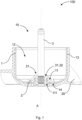
- Figure 1 is a sectional view of a fan 100 with a fan wheel 20 and a rotor 10.
- the rotor 10 comprises a rotor pot 1, a hub 2 and a shaft 3. Furthermore, the hub 2 is formed integrally with the fan wheel 20.
- the rotor pot 1, the hub 2 and the shaft 3 can rotate about a rotation axis A of the rotor 10.
- the shaft 3 is accommodated in a hub bushing 21 of the hub 2 to form a shaft-hub connection.
- the rotor pot 1 has a receptacle 11 for the hub 2 and the hub 2 is attached to the rotor pot 1 at least in the area of the receptacle 11.
- An edge section 111 of the receptacle 11 of the rotor pot 1 extends parallel to the rotation axis A.
- the rotor pot 1 comprises a receiving space 12 for an electric motor and the edge section 111 extends into the receiving space 12.
- the hub 2 completely encloses the receptacle 11.
- the hub 2 is made of a plastic and is molded onto the holder 11 by means of an injection molding process.
- the rotor pot 1 is made of a metallic material.
- the shaft 3 has a section with a cross knurling 31 and recesses 32, which is received in the hub bush 21.
- a plurality of recesses 14 are formed in the receptacle 11, which are distributed in the circumferential direction of the receptacle 11 and arranged adjacent to the edge section 111.
- the hub 2 extends through the recesses 14.
- the recesses 14 are also arranged in a section of the rotor pot 1 which extends in a radial direction with respect to the axis of rotation A.
- the rotor pot 1 is designed as a return ring at least in sections and an outer surface 13 of the rotor pot 1 is completely surrounded by the hub 2 and/or the fan wheel 20. Furthermore, a projection of the hub 2 and/or the fan wheel 20 extends radially with respect to the rotation axis A over an axial end of the rotor pot 1.
- the invention is not limited in its implementation to the preferred embodiments given above. Rather, a number of variants are conceivable which make use of the solution presented even in fundamentally different embodiments.
Landscapes
- Engineering & Computer Science (AREA)
- Mechanical Engineering (AREA)
- Power Engineering (AREA)
- Manufacturing & Machinery (AREA)
- General Engineering & Computer Science (AREA)
- Structures Of Non-Positive Displacement Pumps (AREA)
Abstract
Description
- Die Erfindung betrifft einen Rotor mit einem Rotortopf, einer Nabe und einer Welle. Ferner betrifft die Erfindung ein Verfahren zur Herstellung des Rotors.
- Aus dem Stand der Technik ist eine Vielzahl von Welle-Nabe-Verbindungen zu einem Rotortopf von Rotoren bekannt. Für die Welle-Nabe-Verbindung wird dabei üblicherweise eine metallische Verbindung, eine direkte Verbindung der Welle zum Rückschluss des Rotortopfs, metallische Einlegeteile einer ESM-Variante oder bei einer Anwendung für niedrige Drehzahlen eine Welle-Nabe-Verbindung aus Kunststoff eingesetzt.
- Nachteilig an diesen Lösungen ist beispielsweise, dass die Welle-Nabe-Verbindung eine für einen entsprechenden Anwendungsfall zu geringe Abstützung der Welle aufweist. Darüber hinaus werden radiale Kräfte nicht ausreichend zu einem Rückschluss des Rotors weitergeleitet. Bei einer Welle-Nabe-Verbindung aus Kunststoff kann es zudem auftreten, dass sich der Kunststoff von dem Rückschluss in einem ungewünschten Maße abhebt.
- Der Erfindung liegt deshalb die Aufgabe zugrunde, die vorgenannten Nachteile zu überwinden und einen Rotor sowie ein Verfahren zur Herstellung des Rotors bereitzustellen, bei welchem eine Abstützung der Welle und ein Leiten der radialen Kräfte in den Rückschluss optimiert wird.
- Diese Aufgabe wird durch die Merkmalskombination gemäß Patentanspruch 1 gelöst.
- Erfindungsgemäß wird ein Rotor mit einem Rotortopf, einer Nabe und einer Welle vorgeschlagen, bei welchem der Rotortopf, die Nabe und die Welle um eine Rotationsachse des Rotors rotierbar sind. Dabei ist die Welle in einer Nabenbuchse der Nabe zur Ausbildung einer Welle-Nabe-Verbindung aufgenommen. Der Rotortopf weist eine Aufnahme für die Nabe auf und die Nabe ist zumindest im Bereich der Aufnahme an dem Rotortopf befestigt. Insbesondere sind dabei der Rotortopf und die Welle zur Ausbildung der Nabe, vorzugsweise mit einem Kunststoff, umspritzt. Ferner erstreckt sich ein Randabschnitt der Aufnahme des Rotortopfes zumindest anteilig parallel oder gewinkelt zu der Rotationsachse.
- Vorteilhaft daran ist, dass die Steifigkeit der Welle-Nabe-Verbindung durch die Abstützung der Welle mithilfe des sich zumindest anteilig parallel oder gewinkelt zu der Rotationsachse erstreckenden Randabschnitts der Aufnahme des Rotortopfes sowie vom Rotorboden des Rotortopfes erhöht wird.
- Dabei ist als gewinkelt oder unter einem Winkel zu der Rotationsachse insbesondere zu verstehen, dass der entsprechende Winkel zwischen dem Randabschnitt der Aufnahme des Rotortopfes und der Rotationsachse 0° bis 75° beträgt, vorzugsweise 0° bis 45°, weiter vorzugsweise 0° bis 25°.
- In einer bevorzugten Ausführungsform der Erfindung erstreckt sich der Randabschnitt der Aufnahme parallel zu der Rotationsachse. Dabei ist die Aufnahme insbesondere zylinderförmig ausgebildet. Auf diese Weise wird die Festigkeit der Welle-Nabe-Verbindung und die Abstützung der Welle optimiert.
- In einer vorteilhaften Ausführungsvariante ist vorgesehen, dass der Rotortopf einen Aufnahmeraum für einen Elektromotor umfasst. Dabei erstreckt sich der Randabschnitt in den Aufnahmeraum hinein. Dadurch wird ein benötigter Bauraum des Rotors reduziert und eine Leitung der auf die Welle-Nabe-Verbindung wirkenden axialen Kräfte in den Rotortopf verbessert.
- Vorzugsweise ist der Rotor derart ausgebildet, dass die Welle einen Abschnitt mit einer Rändelung, insbesondere eine Kreuzrändelung, und/oder Einstichen aufweist, welcher in der Nabenbuchse aufgenommen ist. Die Rändelung und die Einstiche leiten die radialen Kräfte über die Nabe zu dem Rotortopf weiter bzw. optimieren die Weiterleitung.
- Der erfindungsgemäße Rotor ist in einer Ausführungsvariante derart ausgebildet, dass die Nabe aus einem Kunststoff hergestellt ist und mittels eines Spritzgussverfahrens zumindest an die Aufnahme angespritzt ist. Ferner ist eine Ausführung günstig, bei welcher der Rotortopf und insbesondere die Welle aus einem metallischen Werkstoff hergestellt ist.
- Erfindungsgemäß ist vorgesehen, dass zumindest eine Aussparung in der Aufnahme ausgebildet ist, welche benachbart zu dem Randabschnitt angeordnet ist. Dabei erstreckt sich die Nabe durch die zumindest eine Aussparung. Die Aussparung ist insbesondere gestanzt und reduziert ein Abheben einer Nabe aus Kunststoff zwischen dem Rotortopf und der Umspritzung. In einer bevorzugten Ausführungsform ist eine Vielzahl von Aussparungen in dem Rotortopf ausgebildet, vorzugsweise fünf Aussparungen. Die entsprechenden Aussparungen sind in einem vorteilhaften Ausführungsbeispiel symmetrisch, insbesondere auf einer Kreisbahn, um den Randabschnitt angeordnet. Vorteilhaft daran ist, dass eine Unwucht des Rotors reduziert bzw. so gering wie möglich ist.
- In einem weiteren Ausführungsbeispiel ist vorgesehen, dass eine Vielzahl von Aussparungen in der Aufnahme ausgebildet ist, welche in Umfangsrichtung der Aufnahme verteilt angeordnet sind. Auf diese Weise wird das Abheben der Nabe vom Rotortopf weiter reduziert.
- Ferner ist eine Ausführung günstig, bei welcher die zumindest eine Aussparung in einem Abschnitt des Rotortopfes angeordnet ist, welcher sich in einer Radialrichtung hinsichtlich der Rotationsachse erstreckt. Vorzugsweise ist die Aussparung unmittelbar angrenzend zu dem sich zumindest anteilig parallel zu der Rotationsachse erstreckenden Randabschnitt der Aufnahme angeordnet.
- In einer Ausführungsvariante der Erfindung ist vorgesehen, dass die Nabe die Aufnahme vollständig umschließt. Dabei ist günstig, dass ein Abheben der Nabe von dem Rotortopf weiter reduziert und die Abstützung der Welle zusätzlich verbessert ist.
- Der erfindungsgemäße Rotor ist in einem Ausführungsbeispiel ausgebildet, dass der Rotortopf zumindest abschnittsweise als ein Rückschlussring ausgebildet ist.
- In einer Ausführungsvariante der Erfindung ist ferner vorgesehen, dass eine Außenmantelfläche des Rotortopfes vollständig von der Nabe und/oder dem Lüfterrad umgeben ist.
- Erfindungsgemäß wird außerdem ein Lüfter mit einem Lüfterrad und einem Rotor gemäß der vorstehenden Offenbarung vorgeschlagen. In einem Ausführungsbeispiel des erfindungsgemäßen Lüfters ist die Nabe mit dem Lüfterrad einstückig und/oder integral ausgebildet ist.
- Erfindungsgemäß wird ferner ein Verfahren zur Herstellung eines Rotors gemäß der vorstehenden Offenbarung vorgeschlagen, bei welchem zunächst ein Tiefziehen des Rotortopfes im Bereich der Aufnahme erfolgt, derart, dass sich der Randabschnitt der Aufnahme des Rotortopfes zumindest anteilig parallel zu der Rotationsachse erstreckt. Anschließend wird zumindest eine Aussparung in der Aufnahme benachbart zu dem Randabschnitt gestanzt. Danach erfolgt ein Umspritzen des Rotortopfes zumindest im Bereich der Aufnahme und der Aussparung. Dabei wird die Nabe ausgebildet und insbesondere die Aufnahme vollständig und die Aussparung zumindest teilweise umspritzt. Außerdem wird beim Umspritzen des Rotortopfes zur Ausbildung der Welle-Nabe-Verbindung ein Abschnitt der Welle, insbesondere des Abschnitts der Welle mit der Rändelung und/oder den Einstichen, umspritzt. Alternativ erfolgt nach dem Umspritzen ein Einfügen der Welle in die Nabenbuchse.
- In einem Ausführungsbeispiel des Verfahrens wird die Welle vor dem Umspritzen in der Aussparung vorbestimmt vorpositioniert.
- Die vorstehend offenbarten Merkmale sind beliebig kombinierbar, soweit dies technisch möglich ist und diese nicht im Widerspruch zueinander stehen.
- Andere vorteilhafte Weiterbildungen der Erfindung sind in den Unteransprüchen gekennzeichnet bzw. werden nachstehend zusammen mit der Beschreibung der bevorzugten Ausführung der Erfindung anhand der Figuren näher dargestellt. Es zeigt:
- Fig. 1
- eine Schnittansicht eines Lüfters mit einem Rotor.
- Die Figuren sind beispielhaft schematisch. Gleiche Bezugszeichen in den Figuren weisen auf gleiche funktionale und/oder strukturelle Merkmale hin.
- In
Figur 1 ist eine Schnittansicht eines Lüfters 100 mit einem Lüfterrad 20 und einem Rotor 10 dargestellt. Der Rotor 10 umfasst einen Rotortopf 1, eine Nabe 2 und eine Welle 3. Ferner ist die Nabe 2 mit dem Lüfterrad 20 einstückig ausgebildet. - Der Rotortopf 1, die Nabe 2 und die Welle 3 sind um eine Rotationsachse A des Rotors 10 rotierbar. Außerdem ist die Welle 3 in einer Nabenbuchse 21 der Nabe 2 zur Ausbildung einer Welle-Nabe-Verbindung aufgenommen. Der Rotortopf 1 weist eine Aufnahme 11 für die Nabe 2 auf und die Nabe 2 ist zumindest im Bereich der Aufnahme 11 an dem Rotortopf 1 befestigt. Dabei erstreckt sich ein Randabschnitt 111 der Aufnahme 11 des Rotortopfes 1 parallel zu der Rotationsachse A. Darüber hinaus umfasst der Rotortopf 1 einen Aufnahmeraum 12 für einen Elektromotor und der Randabschnitt 111 erstreckt sich in den Aufnahmeraum 12 hinein. Die Nabe 2 umschließt die Aufnahme 11 vollständig.
- Des Weiteren ist die Nabe 2 aus einem Kunststoff hergestellt und mittels eines Spritzgussverfahrens an die Aufnahme 11 angespritzt. Der Rotortopf 1 ist aus einem metallischen Werkstoff hergestellt. Die Welle 3 weist einen Abschnitt mit einer Kreuzrändelung 31 und Einstichen 32 auf, welcher in der Nabenbuchse 21 aufgenommen ist.
- Bei dem in
Figur 1 gezeigten Rotor 10 des Lüfters 100 ist eine Vielzahl von Aussparungen 14 in der Aufnahme 11 ausgebildet, welche in Umfangsrichtung der Aufnahme 11 verteilt und benachbart zu dem Randabschnitt 111 angeordnet sind. Dabei erstreckt sich die Nabe 2 durch die Aussparungen 14. Die Aussparungen 14 sind ferner in einem Abschnitt des Rotortopfes 1 angeordnet, welcher sich in einer Radialrichtung hinsichtlich der Rotationsachse A erstreckt. - Darüber hinaus ist der Rotortopf 1 zumindest abschnittsweise als ein Rückschlussring ausgebildet und eine Außenmantelfläche 13 des Rotortopfes 1 ist vollständig von der Nabe 2 und/oder dem Lüfterrad 20 umgeben. Ferner erstreckt sich ein Vorsprung der Nabe 2 und/oder des Lüfterrades 20 radialer Richtung hinsichtlich der Rotationsachse A über ein axiales Ende des Rotortopfes 1.
- Die Erfindung beschränkt sich in ihrer Ausführung nicht auf die vorstehend angegebenen bevorzugten Ausführungsbeispiele. Vielmehr ist eine Anzahl von Varianten denkbar, welche von der dargestellten Lösung auch bei grundsätzlich anders gearteten Ausführungen Gebrauch macht.
Claims (14)
- Rotor (10) mit einem Rotortopf (1), einer Nabe (2) und einer Welle (3),wobei der Rotortopf (1), die Nabe (2) und die Welle (3) um eine Rotationsachse (A) des Rotors (10) rotierbar sind,wobei die Welle (3) in einer Nabenbuchse (21) der Nabe (2) zur Ausbildung einer Welle-Nabe-Verbindung aufgenommen ist,wobei der Rotortopf (1) eine Aufnahme (11) für die Nabe (2) aufweist und die Nabe (2) zumindest im Bereich der Aufnahme (11) an dem Rotortopf (1) befestigt ist,wobei sich ein Randabschnitt (111) der Aufnahme (11) des Rotortopfes (1) zumindest anteilig parallel oder gewinkelt zu der Rotationsachse (A) erstreckt, und wobeizumindest eine Aussparung (14) in der Aufnahme (11) ausgebildet ist, welche benachbart zu dem Randabschnitt (111) angeordnet ist, wobei sich die Nabe (2) durch die zumindest eine Aussparung (14) erstreckt
- Rotor (10) gemäß Anspruch 1, wobei sich der Randabschnitt (111) der Aufnahme (11) parallel zu der Rotationsachse (A) erstreckt.
- Rotor (10) gemäß Anspruch 1 oder 2, wobei der Rotortopf (1) einen Aufnahmeraum (12) für einen Elektromotor umfasst, wobei sich der Randabschnitt (111) in den Aufnahmeraum (12) hinein erstreckt.
- Rotor (10) gemäß einem der Ansprüche 1 bis 3, wobei die Welle (3) einen Abschnitt mit einer Rändelung (31) und/oder Einstichen (32) aufweist, welcher in der Nabenbuchse (21) aufgenommen ist.
- Rotor (10) gemäß einem der vorhergehenden Ansprüche, wobei eine Vielzahl von Aussparungen (14) in der Aufnahme (11) ausgebildet ist, welche in Umfangsrichtung der Aufnahme (11) verteilt angeordnet sind.
- Rotor (10) gemäß einem der vorhergehenden Ansprüche, wobei die zumindest eine Aussparung (14) in einem Abschnitt des Rotortopfes (1) angeordnet ist, welcher sich in einer Radialrichtung hinsichtlich der Rotationsachse (A) erstreckt.
- Rotor (10) gemäß einem der vorherigen Ansprüche, wobei die Nabe (2) die Aufnahme (11) vollständig umschließt.
- Rotor (10) gemäß einem der vorhergehenden Ansprüche, wobei die Nabe (2) aus einem Kunststoff hergestellt und mittels eines Spritzgussverfahrens zumindest an die Aufnahme (11) angespritzt ist.
- Rotor (10) gemäß einem der vorhergehenden Ansprüche, wobei der Rotortopf (1) aus einem metallischen Werkstoff hergestellt ist.
- Rotor (10) gemäß einem der vorhergehenden Ansprüche, wobei der Rotortopf (1) zumindest abschnittsweise als ein Rückschlussring ausgebildet ist.
- Rotor (10) gemäß einem der vorhergehenden Ansprüche, wobei eine Außenmantelfläche (13) des Rotortopfes (1) vollständig von der Nabe (2) und/oder dem Lüfterrad (20) umgeben ist.
- Lüfter (100) mit einem Lüfterrad (20) und einem Rotor (10) gemäß einem der vorhergehenden Ansprüche, wobei insbesondere die Nabe (2) mit dem Lüfterrad (20) einstückig ausgebildet ist.
- Verfahren zur Herstellung eines Rotors (10) gemäß einem der vorhergehenden Ansprüche, welches die Schritte umfasst:a. Tiefziehen des Rotortopfes (1) im Bereich der Aufnahme (11), derart, dass sich der Randabschnitt (111) der Aufnahme (11) des Rotortopfes (1) zumindest anteilig parallel zu der Rotationsachse (A) erstreckt;b. Stanzen von zumindest einer Aussparung (14) in der Aufnahme (11) benachbart zu dem Randabschnitt (111);c. Umspritzen des Rotortopfes (1) zumindest im Bereich der Aufnahme (11) und der Aussparung (14), wobei die Nabe (2) und insbesondere ein Lüfterrad (20) einstückig mit der Nabe (2) ausgebildet wird, wobei insbesondere die Aufnahme (11) vollständig und die Aussparung (14) zumindest teilweise umspritzt wird;d. Einfügen der Welle (3) in die Nabenbuchse (21) oder Umspritzen eines Abschnitts der Welle (3), insbesondere des Abschnitts der Welle (3) mit der Rändelung (31) und/oder den Einstichen (32), beim Umspritzen des Rotortopfes (1) zur Ausbildung der Welle-Nabe-Verbindung.
- Verfahren gemäß Anspruch 13, wobei die Welle (3) vor dem Umspritzen in der Aussparung (14) vorbestimmt vorpositioniert wird.
Applications Claiming Priority (1)
| Application Number | Priority Date | Filing Date | Title |
|---|---|---|---|
| DE102022130321.7A DE102022130321A1 (de) | 2022-11-16 | 2022-11-16 | Rotor und Verfahren zur Herstellung des Rotors |
Publications (1)
| Publication Number | Publication Date |
|---|---|
| EP4372968A1 true EP4372968A1 (de) | 2024-05-22 |
Family
ID=88833739
Family Applications (1)
| Application Number | Title | Priority Date | Filing Date |
|---|---|---|---|
| EP23209802.0A Pending EP4372968A1 (de) | 2022-11-16 | 2023-11-14 | Rotor und verfahren zur herstellung des rotors |
Country Status (4)
| Country | Link |
|---|---|
| US (1) | US20240162772A1 (de) |
| EP (1) | EP4372968A1 (de) |
| CN (1) | CN118054589A (de) |
| DE (1) | DE102022130321A1 (de) |
Citations (4)
| Publication number | Priority date | Publication date | Assignee | Title |
|---|---|---|---|---|
| DE60026770T2 (de) * | 2000-04-19 | 2006-09-07 | Minebea Co., Ltd. | Rotorbefestigung durch Verstemmen oder Punktschweissen |
| US20060208590A1 (en) * | 2005-03-18 | 2006-09-21 | Delta Electronics, Inc. | Rotor |
| US20090148086A1 (en) * | 2007-12-06 | 2009-06-11 | Delta Electronics, Inc. | Fan and rotor of motor thereof |
| CN202260696U (zh) * | 2011-10-12 | 2012-05-30 | 建准电机工业股份有限公司 | 马达转子 |
Family Cites Families (2)
| Publication number | Priority date | Publication date | Assignee | Title |
|---|---|---|---|---|
| DE4440125A1 (de) | 1994-11-10 | 1996-05-15 | Bosch Gmbh Robert | Rotor für Kleinmotoren |
| DE102014000346A1 (de) | 2014-01-16 | 2015-07-16 | Sew-Eurodrive Gmbh & Co Kg | Elektromotor |
-
2022
- 2022-11-16 DE DE102022130321.7A patent/DE102022130321A1/de active Pending
-
2023
- 2023-11-14 CN CN202311509631.1A patent/CN118054589A/zh active Pending
- 2023-11-14 EP EP23209802.0A patent/EP4372968A1/de active Pending
- 2023-11-15 US US18/509,817 patent/US20240162772A1/en active Pending
Patent Citations (4)
| Publication number | Priority date | Publication date | Assignee | Title |
|---|---|---|---|---|
| DE60026770T2 (de) * | 2000-04-19 | 2006-09-07 | Minebea Co., Ltd. | Rotorbefestigung durch Verstemmen oder Punktschweissen |
| US20060208590A1 (en) * | 2005-03-18 | 2006-09-21 | Delta Electronics, Inc. | Rotor |
| US20090148086A1 (en) * | 2007-12-06 | 2009-06-11 | Delta Electronics, Inc. | Fan and rotor of motor thereof |
| CN202260696U (zh) * | 2011-10-12 | 2012-05-30 | 建准电机工业股份有限公司 | 马达转子 |
Also Published As
| Publication number | Publication date |
|---|---|
| DE102022130321A1 (de) | 2024-05-16 |
| CN118054589A (zh) | 2024-05-17 |
| US20240162772A1 (en) | 2024-05-16 |
Similar Documents
| Publication | Publication Date | Title |
|---|---|---|
| EP1934483B1 (de) | Ventilatorrad | |
| DE102012102777B4 (de) | Schraubrad für eine elektromechanische lenkvorrichtung | |
| EP1780445B1 (de) | Zahnrad | |
| WO2022258314A1 (de) | Herstellungsverfahren eines permanentmagnetischen rotors mit nabe | |
| EP2047107A1 (de) | Ventilatorschaufel | |
| DE10122144A1 (de) | Verfahren zum Herstellen eines Zahnrades aus Kunstharz | |
| DE102012102775A1 (de) | Schraubrad für eine elektromechanische lenkvorrichtung | |
| DE102011079226A1 (de) | Flüssigkeitspumpe, insbesondere Wasserpumpe | |
| DE102018127165B4 (de) | Elektrische servolenkungsanordnung | |
| DE102016002832A1 (de) | Lüfter | |
| EP3367541B1 (de) | Rotor eines elektromotors | |
| EP4372968A1 (de) | Rotor und verfahren zur herstellung des rotors | |
| DE102021208941A1 (de) | Elektrische Maschine und Getriebe mit elektrischer Maschine | |
| EP1816729A2 (de) | Elektromotor | |
| EP2689156B1 (de) | Welle-nabe-verbindung und verfahren zum herstellen einer welle-nabe-verbindung | |
| WO2019233874A1 (de) | Elektrischer antriebsmotor, nassläufer-pumpe und haushaltsgerät | |
| EP1209799B1 (de) | Rotor einer elektrischen Maschine und Verfahren zu dessen Herstellung | |
| DE102010018079A1 (de) | Welle mit einem stirnseitig angegossenen Zahnrad und Verfahren zum Herstellen einer solchen Welle | |
| DE102010005490A1 (de) | Rotor einer elektrischen Maschine und Verfahren zur Herstellung eines Rotors einer elektrischen Maschine | |
| EP3729605B1 (de) | Nassläufer-pumpe | |
| EP4321775B1 (de) | Zahnrad mit schrägverzahnung | |
| DE202022100379U1 (de) | Rotornabe für eine Welle-Nabe-Verbindung zur Befestigung an einem Rotortopf eines Rotors | |
| EP4089284B1 (de) | Nassläuferpumpe | |
| EP4283838B1 (de) | Rotoraufnahme zur herstellung einer verbindung einer welle mit einem rotorblechpaket für einen rotor eines innenläufermotors | |
| DE102019212472A1 (de) | Elektrisch kommutierte Maschine |
Legal Events
| Date | Code | Title | Description |
|---|---|---|---|
| PUAI | Public reference made under article 153(3) epc to a published international application that has entered the european phase |
Free format text: ORIGINAL CODE: 0009012 |
|
| STAA | Information on the status of an ep patent application or granted ep patent |
Free format text: STATUS: THE APPLICATION HAS BEEN PUBLISHED |
|
| AK | Designated contracting states |
Kind code of ref document: A1 Designated state(s): AL AT BE BG CH CY CZ DE DK EE ES FI FR GB GR HR HU IE IS IT LI LT LU LV MC ME MK MT NL NO PL PT RO RS SE SI SK SM TR |
|
| STAA | Information on the status of an ep patent application or granted ep patent |
Free format text: STATUS: REQUEST FOR EXAMINATION WAS MADE |
|
| 17P | Request for examination filed |
Effective date: 20241015 |
|
| RBV | Designated contracting states (corrected) |
Designated state(s): AL AT BE BG CH CY CZ DE DK EE ES FI FR GB GR HR HU IE IS IT LI LT LU LV MC ME MK MT NL NO PL PT RO RS SE SI SK SM TR |