EP4372452A1 - Augennaher lichtfeldprojektor mit niedrigem bildrauschen - Google Patents
Augennaher lichtfeldprojektor mit niedrigem bildrauschen Download PDFInfo
- Publication number
- EP4372452A1 EP4372452A1 EP23210393.7A EP23210393A EP4372452A1 EP 4372452 A1 EP4372452 A1 EP 4372452A1 EP 23210393 A EP23210393 A EP 23210393A EP 4372452 A1 EP4372452 A1 EP 4372452A1
- Authority
- EP
- European Patent Office
- Prior art keywords
- combined
- plane
- images
- light
- diffracted
- Prior art date
- Legal status (The legal status is an assumption and is not a legal conclusion. Google has not performed a legal analysis and makes no representation as to the accuracy of the status listed.)
- Granted
Links
Images


Classifications
-
- G—PHYSICS
- G02—OPTICS
- G02B—OPTICAL ELEMENTS, SYSTEMS OR APPARATUS
- G02B27/00—Optical systems or apparatus not provided for by any of the groups G02B1/00 - G02B26/00, G02B30/00
- G02B27/18—Optical systems or apparatus not provided for by any of the groups G02B1/00 - G02B26/00, G02B30/00 for optical projection, e.g. combination of mirror and condenser and objective
-
- H—ELECTRICITY
- H04—ELECTRIC COMMUNICATION TECHNIQUE
- H04N—PICTORIAL COMMUNICATION, e.g. TELEVISION
- H04N9/00—Details of colour television systems
- H04N9/12—Picture reproducers
- H04N9/31—Projection devices for colour picture display, e.g. using electronic spatial light modulators [ESLM]
- H04N9/3102—Projection devices for colour picture display, e.g. using electronic spatial light modulators [ESLM] using two-dimensional electronic spatial light modulators
- H04N9/3111—Projection devices for colour picture display, e.g. using electronic spatial light modulators [ESLM] using two-dimensional electronic spatial light modulators for displaying the colours sequentially, e.g. by using sequentially activated light sources
-
- H—ELECTRICITY
- H04—ELECTRIC COMMUNICATION TECHNIQUE
- H04N—PICTORIAL COMMUNICATION, e.g. TELEVISION
- H04N9/00—Details of colour television systems
- H04N9/12—Picture reproducers
- H04N9/31—Projection devices for colour picture display, e.g. using electronic spatial light modulators [ESLM]
- H04N9/3141—Constructional details thereof
- H04N9/315—Modulator illumination systems
- H04N9/3164—Modulator illumination systems using multiple light sources
-
- G—PHYSICS
- G02—OPTICS
- G02B—OPTICAL ELEMENTS, SYSTEMS OR APPARATUS
- G02B27/00—Optical systems or apparatus not provided for by any of the groups G02B1/00 - G02B26/00, G02B30/00
- G02B27/01—Head-up displays
- G02B27/0101—Head-up displays characterised by optical features
- G02B2027/0112—Head-up displays characterised by optical features comprising device for genereting colour display
-
- G—PHYSICS
- G02—OPTICS
- G02B—OPTICAL ELEMENTS, SYSTEMS OR APPARATUS
- G02B27/00—Optical systems or apparatus not provided for by any of the groups G02B1/00 - G02B26/00, G02B30/00
- G02B27/01—Head-up displays
- G02B27/0101—Head-up displays characterised by optical features
- G02B2027/0118—Head-up displays characterised by optical features comprising devices for improving the contrast of the display / brillance control visibility
- G02B2027/012—Head-up displays characterised by optical features comprising devices for improving the contrast of the display / brillance control visibility comprising devices for attenuating parasitic image effects
-
- G—PHYSICS
- G02—OPTICS
- G02B—OPTICAL ELEMENTS, SYSTEMS OR APPARATUS
- G02B27/00—Optical systems or apparatus not provided for by any of the groups G02B1/00 - G02B26/00, G02B30/00
- G02B27/01—Head-up displays
- G02B27/0101—Head-up displays characterised by optical features
- G02B2027/0145—Head-up displays characterised by optical features creating an intermediate image
-
- G—PHYSICS
- G02—OPTICS
- G02B—OPTICAL ELEMENTS, SYSTEMS OR APPARATUS
- G02B27/00—Optical systems or apparatus not provided for by any of the groups G02B1/00 - G02B26/00, G02B30/00
- G02B27/01—Head-up displays
- G02B27/017—Head mounted
- G02B27/0172—Head mounted characterised by optical features
-
- G—PHYSICS
- G02—OPTICS
- G02B—OPTICAL ELEMENTS, SYSTEMS OR APPARATUS
- G02B30/00—Optical systems or apparatus for producing three-dimensional [3D] effects, e.g. stereoscopic images
- G02B30/10—Optical systems or apparatus for producing three-dimensional [3D] effects, e.g. stereoscopic images using integral imaging methods
Definitions
- the present disclosure concerns a near-eye light field projector that sequentially projects a near-eye projected image to the eyes of a user.
- the near-eye light field projector allows for projecting images where unwanted diffraction orders do not overlap with the image and unwanted diffraction orders are reduced.
- the present disclosure concerns a near-eye light field projector that is adapted for virtual, augmented, mixed reality glasses applications.
- the present disclosure further concerns a wearable device comprising the near-eye light field projector, such as augmented/mixed reality or smart glasses.
- Known near-eye light field projectors comprise a light source typically comprising an array of point-light sources that are collimated into collimated beams.
- the collimated beams illuminate a spatial light modulator (SLM) or diffraction grating under a different set of angles of incidence.
- SLM spatial light modulator
- Each reflected (or transmitted) beam will carry out a certain image information, produced by the modulation of the SLM or diffraction grating.
- Intermediate optics re-images the point-light sources into viewpoints.
- the viewpoints form a light field eye box, allowing a user to see an authentic 3D rendering of a digital scene.
- the SLM or diffraction grating typically comprises a two-dimensional array of pixels.
- the illumination of a two-dimensional array of pixels is equivalent to the illumination of a two-dimensional grating.
- the collimated illumination of a two-dimensional grating may produce a two-dimensional diffraction interference pattern when viewed at infinity.
- the pattern consists of multiple diffraction orders with varying intensity.
- the diffraction interference pattern can be observed in the Fourier plane of the SLM or diffraction grating. In the diffraction interference pattern, the maximum intensity of the center of the diffraction envelope may not match the center of the diffraction pattern.
- the maximum diffraction may not correspond with the zero order, and multiple diffraction orders with relatively high intensities can be observed instead of a single bright image. Thus, this is detrimental to the light-field image since the information a viewer sees comprises multiple images of various intensities (ghost images) coming from various directions.
- Document US20180160784 A1 discloses an optical system that includes a micro-mirror array optical modulator of the digital light processing (DLP) type.
- An optical element has an optimized limiting aperture for defining portions of a modulated light beam that are blocked and remaining portions that are transmitted. The optical element allows for optimizing light collection and contrast in a projection device.
- DLP digital light processing
- the present disclosure concerns a near-eye light field projector comprising a light source comprising a plurality of point-light sources arranged in a light source plane, wherein at least two point-light sources have different wavelengths, and each point-light source is configured to emit an incident light beam.
- the projector further comprises a modulation device configured to diffract the incident light beams and generate diffracted modulated light beams.
- the projector further comprises projection optics configured to project the diffracted modulated light beams and form images in an image plane, the images forming a two-dimensional diffraction interference pattern comprising a plurality of diffraction orders, and relay optics configured to receive the images and to form viewpoints in a viewpoint plane destined to be in a user's eye box.
- the point-light sources are arranged in the light source plane such that the modulated light beams comprise combined modulated light beams forming combined images, each combined image corresponding to an image of the point-light sources of different wavelength, and diffracted modulated light beams forming diffracted images.
- the light field projector further comprises a spatial filter configured to block the diffracted modulated light beams forming the diffracted images, such that the relay optics projects only viewpoints from the combined images.
- Said at least two point-light sources are arranged in the light source plane such that the diffracted images are distant from a combined image by the image separation distance large enough to avoid the diffracted images overlapping the combined image.
- a viewpoint separation distance between two adjacent combined viewpoints is such that at least two combined viewpoints simultaneously enter a viewpoint plane opening of between 2 and 8 mm in the viewpoint plane.
- the present disclosure further concerns a wearable device comprising the near-eye light field projector, such as augmented/mixed reality or smart glasses.
- the near-eye light field projector allows avoiding unwanted diffraction orders of a diffraction interference pattern produced by the modulation device to overlap with the projected image to the eyes of a user.
- the near-eye light field projector further allows point-light sources having different wavelengths to overlap in a single combined image.
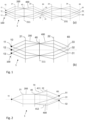
- Fig. 1a represents a sequential near-eye light field projector 1 comprises a light source 100 comprising a plurality of point-light sources 11, 12,13, wherein at least two point-light sources have different wavelengths.
- Each point-light source 11, 12, 13 is configured to emit an incident light beam 200.
- the point-light sources 11, 12, 13 can be arranged in a light source plane 10.
- the point-light sources 11, 12, 13 can comprise LEDs, ⁇ LEDs, lasers, or any other point-light-sources capable of emitting an incident light beam 200.
- Each point-light source 11, 12, 13 can be configured to emit an incident light beam 200 of which a wavelength spectrum is a narrow band. Then, the point-light sources 11, 12,13 can comprise point-light sources capable of emitting a narrow-band incident light beam 200 of which a wavelength spectrum is a narrow band.
- the point-light sources 11, 12, 13 are configured to illuminate a modulation device 40 configured to modulate the incident light beams 200 and generate modulated light beams 400 and a point-light image 31, 32, 33 of each point-light source, for each incident light beam 200.
- the modulation device 40 can comprise a spatial light modulator (SLM) that behaves like a diffraction grating.
- the spatial light modulator 40 can comprise a two-dimensional array of pixels.
- the illumination of a two-dimensional array of pixels is equivalent to the illumination of a two-dimensional grating.
- the SLM 40 can comprise an electrically addressed spatial light modulator ferroelectric liquid crystals (FLCoS) or a digital light processing (DLP).
- FLCoS electrically addressed spatial light modulator ferroelectric liquid crystals
- DLP digital light processing
- a pixel can be a single mirror of a DLP-type SLM or a pixel in an FLCOS device, etc.
- the light field projector 1 further comprises projection optics 21, 22 configured to project the incident light beams 200 and form the point-light images 31, 32, 33 in an image plane 60.
- the projection optics comprise a first projection optics 21 configured to form a first focal plane 211, and a second projection optics 22 configured to project the point-light image 31, 32, 33 of the modulated light beams 400 in the image plane 60.
- the first projection optics 21 can be configured to collimate the incident light beams 200 (see Fig. 2 ), such that the incident light beams 200 are collimated.
- the light field projector 1 can further comprise relay optics.
- the relay optics can comprise a first relay optical element 23 configured to project the modulated light beams 400 and form intermediate images (not shown) in an intermediate image plane 231 and a second relay optical element 24 configured to project the modulated beam light 400 to form viewpoints 81, 82, 83 in a viewpoint plane 80.
- the viewpoint plane 80 can correspond to an eye box of a user. In the absence of diffraction by modulation device 40, the viewpoints 81, 82, 83 appear to be coming from a single point in space with a specific direction.
- the plurality of optical elements 21, 22 and relay optics 23, 24 can comprise lenses or metalenses.
- the near-eye light field projector 1 is configured for sequentially generating the virtual viewpoints 81, 82, 83 that form the light-field.
- Fig. 1b shows a simplified representation of the light field projector 1 without the relay optics 23, 24.
- Fig. 2 shows a simplified representation of the light field projector 1 without the relay optics 23, 24, where the modulation device 40 illuminated by the incident light beams 200 diffracts the incident light beams 200.
- the modulation device 40 projects modulated light beams 400 comprising diffracted beams 411, 412 forming diffracted images 51, 52 (diffraction orders forming a diffraction interference pattern).
- Fig. 1 shows a simplified representation of the light field projector 1 without the relay optics 23, 24, where the modulation device 40 illuminated by the incident light beams 200 diffracts the incident light beams 200.
- the modulation device 40 projects modulated light beams 400 comprising diffracted beams 411, 412 forming diffracted images 51, 52 (diffraction orders forming a diffraction interference pattern).
- the degradation of the information viewed at the viewpoints 81, 82, 83 due to diffraction interference may not be significant when a user is looking at an image in the focal plane of the modulation device 40 (for example at infinity).
- a user's eye focuses on a different plane than the plane where the modulation device 40 is arranged (such as the first focal plane 211), for example a focus plane indicated by numeral 70 in Fig. 2
- the information at the viewpoints 81, 82, 83 appears as coming from multiple directions, for instance, as many directions as there are diffraction orders.
- the diffracted images 51, 52 create a two-dimensional diffraction interference pattern overlapping the point-light images 31 (in the absence of diffraction) in the image plane 60.
- the two-dimensional diffraction interference pattern may comprise multiple diffraction orders with varying intensity. Since the diffraction orders appear in the image plane 60, which may or may not coincide with the Fourier plane of the second projection optics 22, the diffraction pattern forms a grid of diffraction orders which appear in the image plane 60.
- the user sees two identical diffracted images 51, 52 at the same time, the modulated beams 411, 412 being displaced in the focus plane 70.
- This is detrimental to the light-field image as it creates multiple images of various intensities (ghost images) coming from the wrong directions, adding noise.
- the diffraction interference pattern can vary for each wavelength of the incident light beams 200. This results in red, green, and blue modulated beams 411, 412 for a single viewpoint that seem to come from different directions as well.
- modulation device 40 generating a diffraction interference pattern can comprise DLP-type SLM.
- the DLP ® digital micromirror device (DMD) from Texas Instrument comprises tilting mirrors.
- the illumination of an array of tilted mirrors is equivalent to the illumination of a blazed grating.
- Blazed gratings produce diffraction orders where the maximum intensity of the diffracted light does not coincide with the direction of specular reflection.
- the center of the diffraction envelope does not match the center of the diffraction interference pattern.
- the diffraction envelope corresponds to the diffraction pattern of a single pixel of the modulation device 40.
- Fig. 3a shows a simplified representation of the light field projector 1 without the relay optics 23, 24, wherein the light source 100 comprises point-light sources 111, 112, 113 of different wavelengths.
- the point-light sources 111, 112, 113 are spatially separated in the light source plane 10.
- the point-light sources 111, 112, 113 can be arranged in the light source plane 10 such that part of the diffracted modulated light beams 411, 412 are combined (in combined modulated light beams 410) to form combined images 310.
- Each combined image 310 corresponds to an image of the multiple point-light sources 111, 112, 113 of different wavelengths.
- the point-light sources 111, 112, 113 can be arranged in the light source plane 10 by placing the different point-light sources 111,112, 113 at defined positions along the orthogonal axis x, y in the light source plane 10.
- diffracted modulated light beams 411, 412 form diffracted images 511, 512 in the image plane 60.
- the light source 100 is shown comprising three point-light sources 111,112, 113, each having a different wavelength.
- the point-light sources 111, 112, 113 can be further arranged in the light source plane 10 such that the diffracted images 511, 512 are distant from a combined image 310 by an image separation distance d i that is large enough such that the diffracted images 511, 512 do not overlap the combined image 310. Since the image separation distance d i only depends on the wavelength and the grating pitch. Thus, the image separation distance d i depends on the distance set by the shortest wavelength (see Fig. 6 ).
- Fig. 3b shows the light field projector 1 of Fig. 3a further comprising the relay optics 23, 24 and a spatial filter 61.
- the spatial filter 61 is configured to filter unwanted diffraction orders, i.e., to block the propagation of the diffracted modulated light beam 411, 412 that form the diffracted images 511, 512.
- the diffracted modulated light beam 411, 412 thus cannot form diffracted viewpoints in the viewpoint plane 80. Consequently, only the combined modulated light beams 410 are allowed to propagate and pass through the relay optics 23, 24, forming combined viewpoints 810 in the viewpoint plane 80.
- Fig. 3b shows only one combined viewpoint 810
- the light field projector 1 is configured to from at least two combined viewpoint 810, where each combined viewpoint 810 corresponds to a projected image in the viewpoint plane 80, that appears to be always in focus and appears to be coming from a single point in space with a specific direction.
- the spatial filter 61 can comprise an array of pinholes 610 (see Fig. 4 ).
- the point-light sources 111,112, 113 should be arranged in the light source plane 10 such that the positions of the combined images 310 correspond to the positions of the pinholes 610.
- the array can be a regular array or any irregular or random array of pinholes 610.
- the unwanted diffraction orders do not pass through the pinholes 610 and are blocked by the spatial filter 61.
- the point-light sources 111, 112, 113 should be arranged in the light source plane 10 such that the unwanted diffraction orders corresponding to a given combined viewpoint 810 do not overlap another combined viewpoint.
- the pinholes 610 can have a lateral size that is equal or smaller than the image separation distance d i .
- the spatial filter 61 can comprise a wavelength filter.
- the light source 100 comprises point-light sources 111, 112, 113 that emit light in a narrow band
- each point-light source 111, 112, 113 can be individually filtered by the wavelength filter 61.
- the spatial filter 61 can comprise an active shutter array.
- the use of an active shutter array also allows for relaxing the requirement that the point-light sources 111,112, 113 should be arranged in the light source plane 10 such that the unwanted diffraction orders corresponding to a given combined viewpoint 810 do not overlap another combined viewpoint.
- an active shutter array requires a fast shutter speed, matching the high speed of the modulation device 40, and more especially of the SLM.
- the spatial filter 61 can comprise an electro-optical shutter used as a tunable filter.
- the spatial filter 61 can be arranged in the image plane 60.
- the spatial filter 61 can be arranged in the vicinity of the image plane 60, where the distance between the spatial filter 61 and the image plane 60 should be small enough such that the spatial filter 61 allows the selective passage of the combined modulated light beams 410 while blocking the diffracted beams 411, 412.
- the light field projector 1 of Fig. 3b allows for a user to see a light field image with correct depth of focus cues when combined viewpoints 810 reach the user's eye pupil.
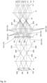
- Fig. 3c shows the light field projector 1 of Fig. 3a and 3b showing the light source 100 comprising point-light sources 111, 112, 113, 121, 122, 123, 131, 132, 133 of different wavelengths.
- the point-light sources 111-133 are spatially separated in the light source plane 10.
- the point-light sources 111,112,113 When illuminating the modulation device 40, the point-light sources 111,112,113 generate modulated light beams comprising diffracted beams 411, 412, 413, the point-light sources 121, 122, 123 generate modulated light beams comprising diffracted beams 421, 422, 423, and the point-light sources 131, 132,133 generate modulated light beams comprising diffracted beams 431, 432, 433.
- the diffracted beams 411-413, 421-423, 431-433 form, respectively, diffracted images 511-513, 521-523, 531-533 (diffraction orders forming
- the point-light sources 111-113 are arranged in the light source plane 10 such that at least a portion of the diffracted modulated light beams 411-413 are combined in a combined modulated light beams 410 to form a combined image 310.
- point-light sources 121-123 and 131-133 are arranged in the light source plane 10 such that at least a portion of the diffracted modulated light beams 421-423 and 431-423 are combined in a combined modulated light beams 420 and 430, respectively, to form a combined image 320 and 330.
- the spatial filter 61 is configured to filter unwanted diffraction orders from the diffracted modulated light beams 411-433.
- the spatial filter 61 is configured to allow only the combined modulated light beams 410, 420, 430 and the combined images 310, 320, 330 to propagate towards the viewpoint plane 80 while preventing the diffracted modulated light beams 411-433 and diffracted images 511-533 to pass through the spatial filter 61.
- only the combined images 310, 320, 330 propagate through the relay optical elements 23, 24, and form combined viewpoints 810, 820, 830 in the viewpoint plane 80.
- the combined viewpoints 810, 820, 830 are configured to be formed in the viewpoint plane 80 (and reach the user's eye) simultaneously. This requires that a viewpoint separation distance d v between two adjacent combined viewpoints 810, 820, 830 is such that at least two but preferably more than three combined viewpoints 810, 820, 830 enter simultaneously a viewpoint plane opening 850 (see Fig. 3c ) in the viewpoint plane 80.
- the viewpoint plane opening 850 can typically correspond to an eye pupil.
- the plurality of combined viewpoints 810, 820, 830 simultaneously entering the viewpoint plane opening 850 allows the formation of a light field image with correct depth cues.
- the viewpoint separation distance d v between two adjacent combined viewpoints 810, 820, 830 is such that at least two but preferably more than three combined viewpoints 810, 820, 830 simultaneously enter the viewpoint plane opening 850 having a lateral size of between 2 and 8 mm.
- the viewpoint separation distance d v is such that more than ten combined viewpoints 810, 820, 830 simultaneously enter the viewpoint plane opening 850 having a lateral size of between 2 and 8 mm.
- Increasing the number of combined viewpoints 810, 820, 830 entering the viewpoint plane opening 850 requires increasing the proximity of the diffraction orders (diffracted images 511-533) relative to the combined images 310, 320, 330 and thus, decreasing the image separation distance d i .
- the spatial filter 61 comprises an array of pinholes 610 and the point light sources 111-133 are arranged in the light source plane 10 such that the unwanted diffraction orders corresponding to a given combined image 310, 320, 330 do not pass through any one of the pinholes 610.
- the light field projector 1 can comprise a greater number of the combined images and combined viewpoints, wherein the plurality of combined viewpoints 810-830 are formed simultaneously in the viewpoint plane 80 to improve the light field image viewed by the user.
- the spatial filter 61 should be configured to let pass only the combined images 310-330 towards the viewpoint plane 80 and block all diffracted images 511-533.
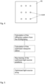
- Fig. 5 illustrates a method for obtaining an optimized arrangement of the point-light sources 111-133 in the light source plane 10, in order to avoid unwanted diffraction orders of a diffraction interference pattern produced by the modulation device do not overlap with the projected image to the eyes of a user, thus minimizing ghost images and noise.
- the method comprises the steps of:
- the diffraction interference pattern forms a grid of diffraction orders which appear in the image plane 60.
- a combined image 310-330 can be formed by the superposition of three point-light sources 111-133, each having a different wavelength. Knowing the diffraction interference patterns for each wavelength, it is possible to calculate the sum of all diffraction interference patterns, as shown in Fig. 6 . This pattern corresponds to the diffraction interference pattern created by a two-dimensional grating, combined with the diffraction of a pixel of the modulation device 40.
- the diffraction interference pattern is generated from a red, green and blue point-light sources 111-133 that are spatially shifted in the light source plane 10 such as to overlap their brightest diffraction orders and forming a white spot, the white spot corresponding to the combined image 310-330.
- Fig. 6 only represents a limited number of diffraction orders.
- the optimized lattice of combined and diffracted images 310-330, 511-533 is then calculated by maximizing the distance between the positions of the combined and diffracted images 511-533 and the secondary diffraction orders in the image plane 60, such that the diffracted images 511-533 are distant from a combined image 310-330 by the image separation distance d i .
- Calculating an optimized arrangement of the point-light sources 111-133 in the light source plane 10 thus depends on the number of combined viewpoints 810-830 entering the viewpoint plane opening 850.
- the image separation distance d i and the viewpoint separation distance d v decrease with increasing the number of combined viewpoints 810-830 entering the viewpoint plane opening 850.
- the optimized arrangement of the point-light sources 111-133 in the light source plane 10 can be calculated such that the viewpoint separation distance d v between two adjacent combined viewpoints 810, 820, 830 is such that at least two but preferably more than three combined viewpoints 810, 820, 830 enter simultaneously a viewpoint plane opening 850 of between 2 and 8 mm in the viewpoint plane 80.
- diffracted viewpoints from the diffracted modulated light beams 411-433 can be separated from each combined viewpoint 810-830 from the combined images 310-330, by a viewpoint separation distance d v corresponding to a diameter of at least 0.2 mm around the combined viewpoint 810-830.
- This condition corresponds to the image separation distance d i multiplied by a magnification factor of the relay optics 23, 24. If the latter condition is fulfilled, the combined viewpoints 810-830 are free of unwanted diffraction orders in a circle of at least 0.2 mm diameter. Unwanted diffraction orders cannot be seen when the combined modulated light beams 410 are projected at the pupil of a user.
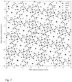
- FIG. 7 An example of an optimized lattice of combined and diffracted images 310-330, 511-533 is represented in Fig. 7 .
- the optimized lattice is obtained with the diffraction interference pattern of the diffracted images 511-533 is generated by red, green, and blue point-light sources 111-133 and the optimized arrangement of the point-light sources 111-133 in the light source plane 10. Only a limited number of diffraction orders are represented in Fig. 7 .
- Calculating an optimized arrangement of the point-light sources 111-133 in the light source plane 10 can be performed by ray tracing using a complete optical model of the near-eye light field projector 1, i.e., a numerical model including the optical components between the light source plane 10 and the image plane 60, allowing to simulate accurately the propagation of light in the near-eye light field projector 1.
- This step can comprise calculating positions for the different point-light sources 111-133 along the orthogonal axis x, y in the light source plane 10.
- the output intensity of the combined images 310-330 can be maximized by selecting the brightest diffraction order that matches a desired combined or diffracted image 310-330, 511-533.
- a refraction angle with which the combined modulated light beam 410-430 outputs the modulation device 40 is selected.
- the refraction angle corresponds to a position in the orthogonal axis x, y of the image plane 60.
- the brightest diffraction order matching a desired combined or diffracted image 310-330, 511-533 may not be the absolute brightest diffraction order.
- the step of calculating an optimized lattice of point-light sources 111-133 in the light source plane 10 can be repeated for each combined or diffracted image 310-330, 511-533 and each wavelength ⁇ .
- An example of a resulting optimized lattice of point-light sources 111-133 producing combined and diffracted images 310-330, 511-533 is shown in Fig. 8 , where the point-light sources 111-133 belonging to a single combined image 310-330 are tagged with the same number.
- the spatial filter 61 comprises an active shutter array (such as an electro-optical shutter) used as a tunable filter
- the optimized arrangement of the point-light sources 111-133 in the light source plane 10 can be calculated individually per diffracted image 310-330, without taking into account possible overlap between different combined images 310-330 and diffracted images 511-533.
- the present disclosure further concerns a wearable device comprising the near-eye light field projector.
- the wearable device can comprise an augmented reality device, a wearable mixed reality device, or smart glasses.
Landscapes
- Physics & Mathematics (AREA)
- Engineering & Computer Science (AREA)
- Multimedia (AREA)
- Signal Processing (AREA)
- General Physics & Mathematics (AREA)
- Optics & Photonics (AREA)
- Diffracting Gratings Or Hologram Optical Elements (AREA)
- Projection Apparatus (AREA)
Applications Claiming Priority (1)
| Application Number | Priority Date | Filing Date | Title |
|---|---|---|---|
| EP22207858.6A EP4372454A1 (de) | 2022-11-16 | 2022-11-16 | Augennaher lichtfeldprojektor mit niedrigem bildrauschen |
Publications (3)
| Publication Number | Publication Date |
|---|---|
| EP4372452A1 true EP4372452A1 (de) | 2024-05-22 |
| EP4372452B1 EP4372452B1 (de) | 2025-09-03 |
| EP4372452C0 EP4372452C0 (de) | 2025-09-03 |
Family
ID=84359189
Family Applications (2)
| Application Number | Title | Priority Date | Filing Date |
|---|---|---|---|
| EP22207858.6A Withdrawn EP4372454A1 (de) | 2022-11-16 | 2022-11-16 | Augennaher lichtfeldprojektor mit niedrigem bildrauschen |
| EP23210393.7A Active EP4372452B1 (de) | 2022-11-16 | 2023-11-16 | Augennaher lichtfeldprojektor mit niedrigem bildrauschen |
Family Applications Before (1)
| Application Number | Title | Priority Date | Filing Date |
|---|---|---|---|
| EP22207858.6A Withdrawn EP4372454A1 (de) | 2022-11-16 | 2022-11-16 | Augennaher lichtfeldprojektor mit niedrigem bildrauschen |
Country Status (2)
| Country | Link |
|---|---|
| EP (2) | EP4372454A1 (de) |
| ES (1) | ES3046815T3 (de) |
Citations (4)
| Publication number | Priority date | Publication date | Assignee | Title |
|---|---|---|---|---|
| EP0949826A2 (de) * | 1998-04-06 | 1999-10-13 | Optimize Incorporated | Binokulares Bildbetrachtungssystem mit intermediären Bildflächen für eine elektronische Anzeigevorrichtung |
| US20110149359A1 (en) * | 2009-12-23 | 2011-06-23 | Seereal Technologies S.A. | Illumination device with a filtering device |
| US20180160784A1 (en) | 2013-03-15 | 2018-06-14 | Imax Theatres International Limited | Projector optimized for mudulator diffraction effects |
| US20200049995A1 (en) * | 2017-02-28 | 2020-02-13 | Cy Vision Inc. | Near-to-eye display device using a spatial light modulator |
-
2022
- 2022-11-16 EP EP22207858.6A patent/EP4372454A1/de not_active Withdrawn
-
2023
- 2023-11-16 ES ES23210393T patent/ES3046815T3/es active Active
- 2023-11-16 EP EP23210393.7A patent/EP4372452B1/de active Active
Patent Citations (4)
| Publication number | Priority date | Publication date | Assignee | Title |
|---|---|---|---|---|
| EP0949826A2 (de) * | 1998-04-06 | 1999-10-13 | Optimize Incorporated | Binokulares Bildbetrachtungssystem mit intermediären Bildflächen für eine elektronische Anzeigevorrichtung |
| US20110149359A1 (en) * | 2009-12-23 | 2011-06-23 | Seereal Technologies S.A. | Illumination device with a filtering device |
| US20180160784A1 (en) | 2013-03-15 | 2018-06-14 | Imax Theatres International Limited | Projector optimized for mudulator diffraction effects |
| US20200049995A1 (en) * | 2017-02-28 | 2020-02-13 | Cy Vision Inc. | Near-to-eye display device using a spatial light modulator |
Also Published As
| Publication number | Publication date |
|---|---|
| EP4372454A1 (de) | 2024-05-22 |
| EP4372452B1 (de) | 2025-09-03 |
| EP4372452C0 (de) | 2025-09-03 |
| ES3046815T3 (en) | 2025-12-02 |
Similar Documents
| Publication | Publication Date | Title |
|---|---|---|
| JP6371377B2 (ja) | マルチ開口投射型ディスプレイおよびそのための単一像生成器 | |
| US9036246B2 (en) | 3-dimensional image display apparatus | |
| EP3528058B1 (de) | Holografische anzeigevorrichtung zur bereitstellung eines erweiterten sichtfensters | |
| US20210382307A1 (en) | Light-field mixed reality system with correct monocular depth cues to a viewer | |
| TWI432922B (zh) | 用於全像重建系統之照明單元 | |
| JP7437498B2 (ja) | 中心窩投影を備えるライトフィールド仮想及び複合現実システム | |
| US12352985B2 (en) | Image display apparatus | |
| US11204587B2 (en) | Holographic display apparatus | |
| JP7569451B2 (ja) | 高解像度ライトフィールド投影装置 | |
| WO2016035607A1 (ja) | 画像表示装置 | |
| WO2015141137A1 (ja) | ホログラムデータ生成方法、ホログラム画像再生方法およびホログラム画像再生装置 | |
| KR20220160607A (ko) | 포비티드 프로젝션 및 확장된 아이-박스 영역을 갖는 근안 이미지 프로젝션 시스템 | |
| EP4372452B1 (de) | Augennaher lichtfeldprojektor mit niedrigem bildrauschen | |
| US20210356745A1 (en) | Method for producing a holographic optical element (hoe), which is provided for projection in a projection system, a holographic optical element of this kind, projection device, lens for data glasses and data glasses of this kind | |
| US20080036974A1 (en) | Display device using diffractive optical modulator and having image distortion function | |
| JP6743985B2 (ja) | カラー画像表示装置、およびそれを用いたカラー画像複製物作成方法、その方法により作成されたカラー画像複製物 | |
| WO2016103869A1 (ja) | 画像処理装置 | |
| US7443586B2 (en) | Display device using single-panel diffractive light modulator | |
| JP6923016B2 (ja) | 光学素子およびプロジェクタ | |
| WO2022113614A1 (ja) | 表示装置 | |
| WO2026017664A1 (en) | Holographic medium, holographic splitter, optical system, method of reconstructing a holographic image and method of recording a hologram | |
| JP2021117480A (ja) | 画像表示装置 |
Legal Events
| Date | Code | Title | Description |
|---|---|---|---|
| PUAI | Public reference made under article 153(3) epc to a published international application that has entered the european phase |
Free format text: ORIGINAL CODE: 0009012 |
|
| STAA | Information on the status of an ep patent application or granted ep patent |
Free format text: STATUS: THE APPLICATION HAS BEEN PUBLISHED |
|
| AK | Designated contracting states |
Kind code of ref document: A1 Designated state(s): AL AT BE BG CH CY CZ DE DK EE ES FI FR GB GR HR HU IE IS IT LI LT LU LV MC ME MK MT NL NO PL PT RO RS SE SI SK SM TR |
|
| STAA | Information on the status of an ep patent application or granted ep patent |
Free format text: STATUS: REQUEST FOR EXAMINATION WAS MADE |
|
| 17P | Request for examination filed |
Effective date: 20241121 |
|
| RBV | Designated contracting states (corrected) |
Designated state(s): AL AT BE BG CH CY CZ DE DK EE ES FI FR GB GR HR HU IE IS IT LI LT LU LV MC ME MK MT NL NO PL PT RO RS SE SI SK SM TR |
|
| GRAP | Despatch of communication of intention to grant a patent |
Free format text: ORIGINAL CODE: EPIDOSNIGR1 |
|
| STAA | Information on the status of an ep patent application or granted ep patent |
Free format text: STATUS: GRANT OF PATENT IS INTENDED |
|
| INTG | Intention to grant announced |
Effective date: 20250326 |
|
| GRAS | Grant fee paid |
Free format text: ORIGINAL CODE: EPIDOSNIGR3 |
|
| GRAA | (expected) grant |
Free format text: ORIGINAL CODE: 0009210 |
|
| STAA | Information on the status of an ep patent application or granted ep patent |
Free format text: STATUS: THE PATENT HAS BEEN GRANTED |
|
| AK | Designated contracting states |
Kind code of ref document: B1 Designated state(s): AL AT BE BG CH CY CZ DE DK EE ES FI FR GB GR HR HU IE IS IT LI LT LU LV MC ME MK MT NL NO PL PT RO RS SE SI SK SM TR |
|
| REG | Reference to a national code |
Ref country code: CH Ref legal event code: EP |
|
| REG | Reference to a national code |
Ref country code: DE Ref legal event code: R096 Ref document number: 602023006357 Country of ref document: DE |
|
| REG | Reference to a national code |
Ref country code: CH Ref legal event code: R17 Free format text: ST27 STATUS EVENT CODE: U-0-0-R10-R17 (AS PROVIDED BY THE NATIONAL OFFICE) Effective date: 20251007 |
|
| REG | Reference to a national code |
Ref country code: IE Ref legal event code: FG4D |
|
| U01 | Request for unitary effect filed |
Effective date: 20250930 |
|
| REG | Reference to a national code |
Ref country code: ES Ref legal event code: FG2A Ref document number: 3046815 Country of ref document: ES Kind code of ref document: T3 Effective date: 20251202 |
|
| U07 | Unitary effect registered |
Designated state(s): AT BE BG DE DK EE FI FR IT LT LU LV MT NL PT RO SE SI Effective date: 20251110 |
|
| U20 | Renewal fee for the european patent with unitary effect paid |
Year of fee payment: 3 Effective date: 20251127 |
|
| PG25 | Lapsed in a contracting state [announced via postgrant information from national office to epo] |
Ref country code: NO Free format text: LAPSE BECAUSE OF FAILURE TO SUBMIT A TRANSLATION OF THE DESCRIPTION OR TO PAY THE FEE WITHIN THE PRESCRIBED TIME-LIMIT Effective date: 20251203 |
|
| PG25 | Lapsed in a contracting state [announced via postgrant information from national office to epo] |
Ref country code: HR Free format text: LAPSE BECAUSE OF FAILURE TO SUBMIT A TRANSLATION OF THE DESCRIPTION OR TO PAY THE FEE WITHIN THE PRESCRIBED TIME-LIMIT Effective date: 20250903 |
|
| PG25 | Lapsed in a contracting state [announced via postgrant information from national office to epo] |
Ref country code: GR Free format text: LAPSE BECAUSE OF FAILURE TO SUBMIT A TRANSLATION OF THE DESCRIPTION OR TO PAY THE FEE WITHIN THE PRESCRIBED TIME-LIMIT Effective date: 20251204 |
|
| PG25 | Lapsed in a contracting state [announced via postgrant information from national office to epo] |
Ref country code: PL Free format text: LAPSE BECAUSE OF FAILURE TO SUBMIT A TRANSLATION OF THE DESCRIPTION OR TO PAY THE FEE WITHIN THE PRESCRIBED TIME-LIMIT Effective date: 20250903 |
|
| PG25 | Lapsed in a contracting state [announced via postgrant information from national office to epo] |
Ref country code: RS Free format text: LAPSE BECAUSE OF FAILURE TO SUBMIT A TRANSLATION OF THE DESCRIPTION OR TO PAY THE FEE WITHIN THE PRESCRIBED TIME-LIMIT Effective date: 20251203 |
|
| PGFP | Annual fee paid to national office [announced via postgrant information from national office to epo] |
Ref country code: ES Payment date: 20251229 Year of fee payment: 3 |
|
| PG25 | Lapsed in a contracting state [announced via postgrant information from national office to epo] |
Ref country code: SM Free format text: LAPSE BECAUSE OF FAILURE TO SUBMIT A TRANSLATION OF THE DESCRIPTION OR TO PAY THE FEE WITHIN THE PRESCRIBED TIME-LIMIT Effective date: 20250903 |
|
| PG25 | Lapsed in a contracting state [announced via postgrant information from national office to epo] |
Ref country code: IS Free format text: LAPSE BECAUSE OF FAILURE TO SUBMIT A TRANSLATION OF THE DESCRIPTION OR TO PAY THE FEE WITHIN THE PRESCRIBED TIME-LIMIT Effective date: 20260103 |