EP4372188B1 - Schloss für ein fenster oder eine tür - Google Patents
Schloss für ein fenster oder eine tür Download PDFInfo
- Publication number
- EP4372188B1 EP4372188B1 EP23200602.3A EP23200602A EP4372188B1 EP 4372188 B1 EP4372188 B1 EP 4372188B1 EP 23200602 A EP23200602 A EP 23200602A EP 4372188 B1 EP4372188 B1 EP 4372188B1
- Authority
- EP
- European Patent Office
- Prior art keywords
- lock
- accordance
- leaf
- rotating handle
- support element
- Prior art date
- Legal status (The legal status is an assumption and is not a legal conclusion. Google has not performed a legal analysis and makes no representation as to the accuracy of the status listed.)
- Active
Links
Images




Classifications
-
- E—FIXED CONSTRUCTIONS
- E05—LOCKS; KEYS; WINDOW OR DOOR FITTINGS; SAFES
- E05B—LOCKS; ACCESSORIES THEREFOR; HANDCUFFS
- E05B1/00—Knobs or handles for wings; Knobs, handles, or press buttons for locks or latches on wings
- E05B1/0015—Knobs or handles which do not operate the bolt or lock, e.g. non-movable; Mounting thereof
-
- E—FIXED CONSTRUCTIONS
- E05—LOCKS; KEYS; WINDOW OR DOOR FITTINGS; SAFES
- E05B—LOCKS; ACCESSORIES THEREFOR; HANDCUFFS
- E05B1/00—Knobs or handles for wings; Knobs, handles, or press buttons for locks or latches on wings
- E05B1/003—Handles pivoted about an axis perpendicular to the wing
-
- E—FIXED CONSTRUCTIONS
- E05—LOCKS; KEYS; WINDOW OR DOOR FITTINGS; SAFES
- E05B—LOCKS; ACCESSORIES THEREFOR; HANDCUFFS
- E05B3/00—Fastening knobs or handles to lock or latch parts
-
- E—FIXED CONSTRUCTIONS
- E05—LOCKS; KEYS; WINDOW OR DOOR FITTINGS; SAFES
- E05B—LOCKS; ACCESSORIES THEREFOR; HANDCUFFS
- E05B3/00—Fastening knobs or handles to lock or latch parts
- E05B3/06—Fastening knobs or handles to lock or latch parts by means arranged in or on the rose or escutcheon
-
- E—FIXED CONSTRUCTIONS
- E05—LOCKS; KEYS; WINDOW OR DOOR FITTINGS; SAFES
- E05B—LOCKS; ACCESSORIES THEREFOR; HANDCUFFS
- E05B65/00—Locks or fastenings for special use
- E05B65/0035—Locks or fastenings for special use for privacy rooms, e.g. bathrooms
-
- E—FIXED CONSTRUCTIONS
- E05—LOCKS; KEYS; WINDOW OR DOOR FITTINGS; SAFES
- E05C—BOLTS OR FASTENING DEVICES FOR WINGS, SPECIALLY FOR DOORS OR WINDOWS
- E05C19/00—Other devices specially designed for securing wings, e.g. with suction cups
- E05C19/16—Devices holding the wing by magnetic or electromagnetic attraction
-
- E—FIXED CONSTRUCTIONS
- E05—LOCKS; KEYS; WINDOW OR DOOR FITTINGS; SAFES
- E05B—LOCKS; ACCESSORIES THEREFOR; HANDCUFFS
- E05B9/00—Lock casings or latch-mechanism casings ; Fastening locks or fasteners or parts thereof to the wing
- E05B9/04—Casings of cylinder locks
- E05B2009/046—Cylinder locks operated by knobs or handles
Definitions
- the present invention relates to a lock for a door or a window.
- the present invention makes reference to the technical field of door closing devices.
- such locks have a lock body that can be housed in the thickness of the leaf and comprises the bolt.
- the bolt is moved between the extracted position and the retracted position thanks to the rotation of a square bar that passes through the lock body.
- Such locks further comprise a pair of handles at least partially recessed into the exposed surface of the leaf and at least one of which is connected to the square bar so as to control the movement of the bolt.
- each handle comprises a receptacle adapted to be recessed into the surface of the leaf and configured to receive an actuating member, typically a latch, directly connected to the square bar.
- an actuating member typically a latch
- the latch In the handle positioned on the other side, by contrast, typically on the outside of the room, the latch cannot be gripped, but rather has an indentation for a tool, or a coin, so as to allow only a possible emergency opening of the lock and, therefore, of the door or window.
- each receptacle requires a recessed seat having a minimum depth, so it is essential that the leaf have a sufficient thickness, both for installing the lock and for creating the recessed seat.
- handles are not very ergonomic and, especially in the case of hinged leaves, they require auxiliary gripping members, typically extractable. This circumstance introduces constructive complications and higher costs.
- Document DE 29707200 U1 in accordance with the preamble of claim 1, describes a lock for doors of bathrooms or toilets with a rotatable handle disposed inside the room and a display device positioned outside the room to display the "closed" status.
- one object of the present invention is to provide a lock that can be mounted on leaves having reduced thicknesses.
- a further object of the present invention is to propose a lock that can be rapidly and easily installed.
- Another object of the present invention is to provide a lock that is simple to use.
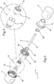
- a lock for a door or a window according to the invention has been denoted in its entirety by the reference number 1.
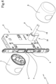
- the lock 1 comprises a lock body 2 connectable to a leaf "A" ( figures 4 and 8 ) of a door or a window.
- the lock body 2 comprises a locking element 3 that is reversibly movable between a retracted position, in which it is at least partly housed inside the lock body 2, and an extracted position, in which it is at least partly projecting from the lock body 2 so as to define a condition of closure of the door or the window.
- the locking element 3 comprises a bolt 4.
- the lock body 2 can comprise a magnetic retaining device 5 configured to interact magnetically with a counter-plate (not illustrated) installed on the frame of the door or the window. In this manner, the leaf “A” can be kept firmly in a closed position without the activation of the bolt 4.
- the lock 1 further comprises an actuating means 6 for moving the locking element 3.
- the actuating means 6 comprises a bar 13 with a polygonal cross section which is active on the lock body 2 and reversibly rotatable in order to move the locking element 3 at least between the retracted position and the extracted position.
- the bar 13 can have a quadrangular cross section, preferably a square one. It should be underscored that the kinematic mechanism of the transmission of motion between the bar 13 and the bolt 4 is of a known type and not illustrated.
- the lock 1 comprises a fixed handle 7 that is connectable to the leaf "A” and can be gripped by a user.
- the fixed handle 7 is solidly joined to the lock body 2.
- the lock 1 comprises a rotating handle 8 that is connectable to the leaf "A” and can be gripped by a user.
- the rotating handle 8 is solidly coupled to the actuating means 6 and rotatable relative to the lock body 2 in order to move the locking element 3 between the extracted position and the retracted position.
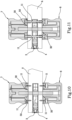
- the actuating means 6 and at least the rotating handle 8 can be telescopically coupled to enable the lock to be adapted to the thickness of the leaf.
- the fixed handle 7 and the rotating handle 8 can be disposed, respectively, on the surface of the leaf outside a room and on the surface of the leaf inside a room.
- the actuating means 6 is disposed at least partly inside the rotating handle 8.
- the rotating handle 8 can be configured to house the actuating means 6 at least partly, thereby imparting a particular aesthetic appeal to the lock 1.
- the lock 1 further comprises a first support element 9 and a second support element 10, each having a longitudinal dimension of extension such that they take on a configuration, during use, projecting from a leaf "A".
- the fixed handle 7 and the rotating handle 8 can be fitted over the first support element 9 and the second support element 10, respectively.
- this solution is highly ergonomic, as it simplifies the procedure of locking the leaf, allowing the leaf to be closed and subsequently locked with a single continuous sequence of movements of the same hand.
- this solution makes it possible to simplify and speed up the installation of the lock by minimising the milling operations on the leaf "A" compared to the prior art.
- the present lock 1 can be advantageously mounted on leaves having a reduced thickness, even only slightly larger than that of the lock body 2. Therefore, the lock according to the invention can have particular and effective application on glass leaves and, in general, on leaves having a thickness equal to or less than 14 millimetres.
- the first support element 9 and the second support element 10 can be completely housed inside the fixed handle 7 and the rotating handle 8, thus being, during use, substantially out of view so as to increase the aesthetic appeal of the lock 1.
- the fixed handle 7 and/or the rotating handle 8 can be in the form of a knob, thus ensuring optimal ergonomics and a high aesthetic appeal of the lock 1.
- the handle can have a different form, for example to satisfy the user's needs, without altering the inventive concept of the present invention.
- the lock 1 comprises a circlip 30 active on the rotating handle 8 in order to keep it fitted over the second support element 10.
- the lock 1 comprises a connecting grub screw 40 active on the fixed handle 7 in order to keep it fitted over the first support element 9.
- the first support element 9 and the second support element 10 are connectable to the leaf "A" and/or lock body 2 so that the latter is at least partly interposed between them, and thus between the fixed handle 7 and the rotating handle 8.
- the lock 1 can comprise fixing elements 11, for example screws, suitable for connecting the first support element 9 and the second support element 10 to the leaf "A", thereby ensuring particular stability and robustness of the lock 1.
- the fixing elements 11 are connected to the first support element 9 and second support element 10 in such a way that, during use, the fixed handle 7 and the rotating handle 8 are opposite relative to the leaf "A" of the door or window and, preferably, have respective axes of extension that coincide.
- the axes of extension of the handles 7, 8 coincide with the axis of extension of the bar 13.
- the first support element 9 and the second support element 10 can have, respectively, a pair of housings 50 adapted to receive, by insertion, the fixing elements 11.
- the fixing elements 11 can comprise four screws, each of which inserted into a corresponding housing 50 and screwed, when in use, directly onto the leaf "A".
- the fixing elements 11 can, when in use, pass through the leaf "A" and the lock body 2.
- the fixing elements 11 can be inserted into the housings 50 of the first support element 9 so as to be connected to respective housings 50 of the second support element 10, in such a way as to maintain the first support element 9 and the second support element 10 constrained to the leaf "A".
- the fixing elements 11 can be inserted into the housings 50 of the first support element 9 and screwed into a respective female screw inserted in the housings 50 of the second support element 10.
- the fixed handle 7 and the rotating handle 8 can be fitted, during use, over the support elements 9, 10, they hide the fixing elements 11 from view, thus imparting aesthetic quality to the lock 1.
- the lock 1 can comprise an auxiliary control device 12 at least partly housed in the fixed handle 7.
- the auxiliary control device 12 can be activated in order to move the locking element 3 at least from the extracted position to the retracted position.
- the auxiliary control device 12 can define, for example, an emergency opening system for the door or window.
- the auxiliary control device 12 can further be activated in order to reversibly move the locking element 3 from the retracted position to the extracted position.
- the auxiliary control device 12 comprises a control member 14 solidly joined to the bar 13 and having a seat 15, preferably an indentation, adapted to receive a tool for external actuation by a user.
- the tool for external actuation can consist in a coin and/or the tip of a screwdriver.
- control member 14 is fitted over the bar 13 and coupled thereto by virtue of their mating shape, in such a way as to optimise the overall dimensions of the lock 1.
- control member 14 has a first portion 16, fitted over the bar 13, and a second portion 17 exposed to view (when the lock is in use) and bearing the seat 15.
- the first portion 16 and the second portion 17 are reciprocally constrained by virtue of their mating shape, thus minimising the connection elements and simplifying the manufacturing process.
- first portion 16 and the second portion 17 can be reciprocally press fitted.
- first portion 16 is connected to the bar 13 by means of a circlip 30 which ensures an adequate positioning thereof relative to the first support element 9 of the fixed handle 7.
- the lock 1 comprises a cylinder 18 having a shank 19 over which the rotating handle 8 is fitted.
- the rotating handle 8 and the shank 19 are reciprocally coupled in rotation by means of a coupling grub screw 40.
- the shank 19 essentially defines the actuating means 6.
- the fixed handle 7 has an access opening 20 for accessing the cylinder 18 to allow the insertion of a key "C" by a user.
- the cylinder 18 can also perform the function of an auxiliary control device for emergency opening.
- a plug 21 is further present; it is insertable into the access opening 20 and provided with a through slot adapted to allow the insertion of the key "C".
- the plug 21 can be connected to the fixed handle 7 by means of a circlip 30 which ensures the correct positioning thereof relative to the access opening 20.
- the present invention relates to a door or window comprising a supporting frame, a leaf "A" which is reversibly movable relative to the frame between at least an open position and a closed position, and a lock in accordance with what was previously described.
- the present invention achieves the proposed objects by providing a lock for a door or a window that can also be installed on leaves having reduced thicknesses.
- the lock according to the invention is capable of enhancing the ergonomics and convenience for the user thanks to the presence of a fixed handle and a rotating handle which can be fitted, during use, over a first and a second support element so as to take on a configuration of projecting from the leaf.
- the present invention provides a lock with a "knob"-style handle with a gripping system and a leaf stop system in a single solution for locks with one or more points of activation of the lock for the leaf.
Landscapes
- Engineering & Computer Science (AREA)
- Mechanical Engineering (AREA)
- Physics & Mathematics (AREA)
- Electromagnetism (AREA)
- Lock And Its Accessories (AREA)
Claims (18)
- Schloss (1) für eine Tür oder ein Fenster, Folgendes umfassend:- einen Schlosskörper (2), der mit einem Flügel einer Tür oder eines Fensters verbindbar ist und ein Verriegelungselement (3) umfasst, das zwischen einer zurückgezogenen Position, in der es mindestens teilweise im Inneren des Schlosskörpers (2) untergebracht ist, und einer herausgezogenen Position, in der es mindestens teilweise aus dem Schlosskörper (2) vorsteht, reversibel beweglich ist, um einen Schließzustand der Tür oder des Fensters zu definieren;- ein Betätigungsmittel (6) zum Bewegen des Verriegelungselements (3);- einen feststehenden Griff (7), der mit dem Flügel (A) verbindbar ist und von einem Benutzer ergriffen werden kann, wobei der feststehende Griff (7) im Verhältnis zum Schlosskörper (2) fest ist;- einen drehbaren Griff (8), der mit dem Flügel (A) verbindbar ist und von einem Benutzer ergriffen werden kann, wobei der drehbare Griff (8) mit dem Betätigungsmittel (6) gekoppelt und im Verhältnis zum Schlosskörper (2) drehbar ist, um das Verriegelungselement (3) zwischen der herausgezogenen Position und der zurückgezogenen Position zu bewegen; dadurch gekennzeichnet, dass das Schloss- ein erstes und ein zweites Tragelement (9, 10) umfasst, die jeweils eine Längserstreckungsabmessung aufweisen, so dass sie im Gebrauch eine von einem Flügel (A) vorstehende Konfiguration einnehmen; und wobei der feststehende Griff (7) und der drehbare Griff (8) auf das erste Tragelement (9) bzw. das zweite Tragelement (10) aufgesteckt werden können.
- Schloss nach Anspruch 1, wobei das erste und das zweite Tragelement (9, 10) mit dem Flügel (A) und/oder dem Schlosskörper verbindbar sind, so dass letzterer mindestens teilweise zwischen ihnen eingefügt ist.
- Schloss nach Anspruch 1 oder 2, das mindestens ein Befestigungselement (11) umfasst, das in eine Durchgangsöffnung des Schlosskörpers (2) einsetzbar ist, um das erste Tragelement (9) und das zweite Tragelement (10) zu verbinden.
- Schloss nach Anspruch 3, wobei das erste Tragelement (9) und das zweite Tragelement (10) dazu eingerichtet sind, das mindestens eine Befestigungselement (11) aufzunehmen, indem dieses mindestens teilweise eingesetzt wird, so dass der drehbare Griff (8) und der feststehende Griff (7) im Gebrauch im Verhältnis zu dem Flügel (A) der Tür oder des Fensters gegenüberliegend sind und vorzugsweise jeweilige Erstreckungsachsen, die zusammenfallen, aufweisen.
- Schloss nach einem oder mehreren der vorhergehenden Ansprüche, das mindestens einen Sicherungsring (30) umfasst, der auf den drehbaren Griff (8) wirkt, um ihn auf dem zweiten Tragelement (10) aufgesteckt zu halten.
- Schloss nach einem oder mehreren der vorhergehenden Ansprüche, wobei das Betätigungsmittel (6) mindestens teilweise innerhalb des drehbaren Griffs (8) positioniert ist.
- Schloss nach einem oder mehreren der vorhergehenden Ansprüche, das eine Hilfssteuervorrichtung (12) umfasst, die mindestens teilweise im feststehenden Griff (7) untergebracht ist, wobei die Hilfssteuervorrichtung (12) aktivierbar ist, um das Verriegelungselement (3) mindestens von der herausgezogenen Position in die zurückgezogene Position zu bewegen.
- Schloss nach einem oder mehreren der vorhergehenden Ansprüche, wobei das Betätigungsmittel (6) eine Stange (13) mit polygonalem Querschnitt umfasst, die auf den Schlosskörper wirkt und reversibel drehbar ist, um das Verriegelungselement (3) mindestens zwischen der zurückgezogenen Position und der ausgezogenen Position zu bewegen.
- Schloss nach Anspruch 8, wenn er von Anspruch 7 abhängt, wobei die Hilfssteuervorrichtung (12) ein Steuerglied (14) umfasst, das fest mit der Stange (13) verbunden ist und einen Sitz (15) aufweist, der dazu ausgelegt ist, ein Werkzeug aufzunehmen, das von außen durch einen Benutzer betätigt wird.
- Schloss nach Anspruch 9, wobei das Steuerglied (14) auf die Stange (13) aufgesteckt ist und aufgrund ihrer Komplementärform mit dieser gekoppelt ist.
- Schloss nach Anspruch 10, wobei das Steuerglied (14) einen ersten Abschnitt (16), der auf die Stange (13) aufgesteckt ist, und einen zweiten Abschnitt (17) aufweist, der den Sitz (15) definiert; und wobei der erste Abschnitt (16) und der zweite Abschnitt (17) aufgrund ihrer Komplementärform wechselseitig eingeschränkt sind.
- Schloss nach Anspruch 1, das einen Zylinder (18) umfasst, der einem Schaft (19) aufweist, der so ausgelegt ist, dass der drehbare Griff (8) auf ihm aufgesteckt ist, wobei der Schaft (19) mindestens teilweise das Betätigungsmittel (6) definiert.
- Schloss nach Anspruch 12, wobei der feststehende Griff (7) eine Zugangsöffnung (20) für den Zugang zu dem Zylinder (18) aufweist, um das Einführen eines Schlüssels (C) in den Zylinder (18) durch einen Benutzer zu ermöglichen.
- Schloss nach Anspruch 12 oder 13, das eine Verbindungsmadenschraube (40) umfasst, die zwischen dem drehbaren Griff (8) und dem Schaft (19) wirkt, um die beiden wechselseitig drehbar zu koppeln.
- Schloss nach einem oder mehreren der vorhergehenden Ansprüche, wobei der feststehende Griff (7) und/oder der drehbare Griff (8) eine knaufartige Form aufweisen.
- Schloss nach einem oder mehreren der vorhergehenden Ansprüche, wobei das Betätigungsmittel (6) und mindestens der drehbare Griff (8) teleskopisch gekoppelt sind, damit sie an die Dicke des Flügels (A) anpassbar sind.
- Schloss nach einem oder mehreren der vorhergehenden Ansprüche, wobei der Schlosskörper ferner eine magnetische Haltevorrichtung (5) umfasst, die dazu eingerichtet ist, magnetisch mit einer am Rahmen der Tür oder des Fensters installierten Gegenplatte zusammenzuwirken.
- Tür oder Fenster, Folgendes umfassend:- einen Tragrahmen;- einen Flügel (A), der im Verhältnis zum Rahmen beweglich ist;- ein Schloss (1) nach einem oder mehreren der vorhergehenden Ansprüche, das am Flügel (A) installiert ist.
Applications Claiming Priority (1)
| Application Number | Priority Date | Filing Date | Title |
|---|---|---|---|
| IT202200023691 | 2022-11-16 |
Publications (2)
| Publication Number | Publication Date |
|---|---|
| EP4372188A1 EP4372188A1 (de) | 2024-05-22 |
| EP4372188B1 true EP4372188B1 (de) | 2025-02-12 |
Family
ID=85172722
Family Applications (1)
| Application Number | Title | Priority Date | Filing Date |
|---|---|---|---|
| EP23200602.3A Active EP4372188B1 (de) | 2022-11-16 | 2023-09-28 | Schloss für ein fenster oder eine tür |
Country Status (1)
| Country | Link |
|---|---|
| EP (1) | EP4372188B1 (de) |
Family Cites Families (4)
| Publication number | Priority date | Publication date | Assignee | Title |
|---|---|---|---|---|
| GB2297798A (en) * | 1995-02-09 | 1996-08-14 | Edward Connolly | A lever lock door or window catch arrangement |
| DE29707200U1 (de) | 1997-04-23 | 1997-06-12 | Dorma Gmbh + Co. Kg, 58256 Ennepetal | Türverriegelung für Bad- oder Toilettentüren |
| DE10210479B4 (de) * | 2002-03-11 | 2007-06-21 | Dorma Gmbh + Co. Kg | Beschlagsgarnitur |
| CN104631975B (zh) * | 2015-01-30 | 2016-06-15 | 济南大学 | 公共卫生间门锁装置 |
-
2023
- 2023-09-28 EP EP23200602.3A patent/EP4372188B1/de active Active
Also Published As
| Publication number | Publication date |
|---|---|
| EP4372188A1 (de) | 2024-05-22 |
Similar Documents
| Publication | Publication Date | Title |
|---|---|---|
| US4934800A (en) | Low cost lever handle entry function | |
| KR100875397B1 (ko) | 회전 및 병진의 조합된 래치동작을 하는 키조작식 래치 | |
| US8522582B2 (en) | Dual lock apparatus | |
| US6023952A (en) | Door handle with offset lock actuator | |
| EP3212867B1 (de) | Verbundenes schloss mit direktantrieb für einstellbaren abstand zwischen riegel und schlossfalle | |
| EP2985397B1 (de) | Einsteckschloss | |
| TW201344025A (zh) | 把手致動鎖 | |
| CN101395329A (zh) | 具有闭锁插入物的手柄 | |
| US10851565B1 (en) | Rotary lock actuator | |
| AU2020309101B2 (en) | A lock body for a sliding door | |
| EP2617919B1 (de) | Betriebsgriff | |
| EP4372188B1 (de) | Schloss für ein fenster oder eine tür | |
| EP3940176B1 (de) | Nabe für verriegelungsvorrichtung und verriegelungsvorrichtung | |
| EP3623548B1 (de) | Verschlusssystem für einen flügel eines fensters oder einer tür | |
| EP3906347B1 (de) | Griffanordnung | |
| CN218092491U (zh) | 执手及平推窗 | |
| AU2019229347B2 (en) | Magnetic Door Latch Mechanism and Assembly | |
| KR100875296B1 (ko) | 모티스 락용 래치 볼트 및 이를 구비한 모티스 락 | |
| EP1160403B1 (de) | Kraftfahrzeugschloss | |
| KR101737035B1 (ko) | 푸시 앤 풀 타입 도어록 | |
| EP3940178B1 (de) | Halterung für lange deckelgriffe | |
| RU2797579C2 (ru) | Антипаниковый замок с очень гибким использованием | |
| AU2019232781A1 (en) | Latch and method of latch installation | |
| GB2244755A (en) | A handle assembly for a pivoted window or door | |
| CN210316906U (zh) | 推拉式锁具 |
Legal Events
| Date | Code | Title | Description |
|---|---|---|---|
| PUAI | Public reference made under article 153(3) epc to a published international application that has entered the european phase |
Free format text: ORIGINAL CODE: 0009012 |
|
| STAA | Information on the status of an ep patent application or granted ep patent |
Free format text: STATUS: REQUEST FOR EXAMINATION WAS MADE |
|
| 17P | Request for examination filed |
Effective date: 20240308 |
|
| AK | Designated contracting states |
Kind code of ref document: A1 Designated state(s): AL AT BE BG CH CY CZ DE DK EE ES FI FR GB GR HR HU IE IS IT LI LT LU LV MC ME MK MT NL NO PL PT RO RS SE SI SK SM TR |
|
| P01 | Opt-out of the competence of the unified patent court (upc) registered |
Free format text: CASE NUMBER: APP_49731/2024 Effective date: 20240903 |
|
| GRAP | Despatch of communication of intention to grant a patent |
Free format text: ORIGINAL CODE: EPIDOSNIGR1 |
|
| STAA | Information on the status of an ep patent application or granted ep patent |
Free format text: STATUS: GRANT OF PATENT IS INTENDED |
|
| GRAS | Grant fee paid |
Free format text: ORIGINAL CODE: EPIDOSNIGR3 |
|
| INTG | Intention to grant announced |
Effective date: 20241129 |
|
| GRAA | (expected) grant |
Free format text: ORIGINAL CODE: 0009210 |
|
| STAA | Information on the status of an ep patent application or granted ep patent |
Free format text: STATUS: THE PATENT HAS BEEN GRANTED |
|
| AK | Designated contracting states |
Kind code of ref document: B1 Designated state(s): AL AT BE BG CH CY CZ DE DK EE ES FI FR GB GR HR HU IE IS IT LI LT LU LV MC ME MK MT NL NO PL PT RO RS SE SI SK SM TR |
|
| REG | Reference to a national code |
Ref country code: GB Ref legal event code: FG4D |
|
| REG | Reference to a national code |
Ref country code: CH Ref legal event code: EP |
|
| REG | Reference to a national code |
Ref country code: DE Ref legal event code: R096 Ref document number: 602023002011 Country of ref document: DE |
|
| REG | Reference to a national code |
Ref country code: IE Ref legal event code: FG4D |
|
| REG | Reference to a national code |
Ref country code: NL Ref legal event code: MP Effective date: 20250212 |
|
| PG25 | Lapsed in a contracting state [announced via postgrant information from national office to epo] |
Ref country code: RS Free format text: LAPSE BECAUSE OF FAILURE TO SUBMIT A TRANSLATION OF THE DESCRIPTION OR TO PAY THE FEE WITHIN THE PRESCRIBED TIME-LIMIT Effective date: 20250512 |
|
| PG25 | Lapsed in a contracting state [announced via postgrant information from national office to epo] |
Ref country code: FI Free format text: LAPSE BECAUSE OF FAILURE TO SUBMIT A TRANSLATION OF THE DESCRIPTION OR TO PAY THE FEE WITHIN THE PRESCRIBED TIME-LIMIT Effective date: 20250212 |
|
| PG25 | Lapsed in a contracting state [announced via postgrant information from national office to epo] |
Ref country code: PL Free format text: LAPSE BECAUSE OF FAILURE TO SUBMIT A TRANSLATION OF THE DESCRIPTION OR TO PAY THE FEE WITHIN THE PRESCRIBED TIME-LIMIT Effective date: 20250212 |
|
| PG25 | Lapsed in a contracting state [announced via postgrant information from national office to epo] |
Ref country code: ES Free format text: LAPSE BECAUSE OF FAILURE TO SUBMIT A TRANSLATION OF THE DESCRIPTION OR TO PAY THE FEE WITHIN THE PRESCRIBED TIME-LIMIT Effective date: 20250212 |
|
| REG | Reference to a national code |
Ref country code: LT Ref legal event code: MG9D |
|
| PG25 | Lapsed in a contracting state [announced via postgrant information from national office to epo] |
Ref country code: IS Free format text: LAPSE BECAUSE OF FAILURE TO SUBMIT A TRANSLATION OF THE DESCRIPTION OR TO PAY THE FEE WITHIN THE PRESCRIBED TIME-LIMIT Effective date: 20250612 Ref country code: NO Free format text: LAPSE BECAUSE OF FAILURE TO SUBMIT A TRANSLATION OF THE DESCRIPTION OR TO PAY THE FEE WITHIN THE PRESCRIBED TIME-LIMIT Effective date: 20250512 |
|
| PG25 | Lapsed in a contracting state [announced via postgrant information from national office to epo] |
Ref country code: NL Free format text: LAPSE BECAUSE OF FAILURE TO SUBMIT A TRANSLATION OF THE DESCRIPTION OR TO PAY THE FEE WITHIN THE PRESCRIBED TIME-LIMIT Effective date: 20250212 |
|
| PG25 | Lapsed in a contracting state [announced via postgrant information from national office to epo] |
Ref country code: HR Free format text: LAPSE BECAUSE OF FAILURE TO SUBMIT A TRANSLATION OF THE DESCRIPTION OR TO PAY THE FEE WITHIN THE PRESCRIBED TIME-LIMIT Effective date: 20250212 |
|
| PG25 | Lapsed in a contracting state [announced via postgrant information from national office to epo] |
Ref country code: LV Free format text: LAPSE BECAUSE OF FAILURE TO SUBMIT A TRANSLATION OF THE DESCRIPTION OR TO PAY THE FEE WITHIN THE PRESCRIBED TIME-LIMIT Effective date: 20250212 Ref country code: PT Free format text: LAPSE BECAUSE OF FAILURE TO SUBMIT A TRANSLATION OF THE DESCRIPTION OR TO PAY THE FEE WITHIN THE PRESCRIBED TIME-LIMIT Effective date: 20250612 |
|
| PG25 | Lapsed in a contracting state [announced via postgrant information from national office to epo] |
Ref country code: GR Free format text: LAPSE BECAUSE OF FAILURE TO SUBMIT A TRANSLATION OF THE DESCRIPTION OR TO PAY THE FEE WITHIN THE PRESCRIBED TIME-LIMIT Effective date: 20250513 Ref country code: BG Free format text: LAPSE BECAUSE OF FAILURE TO SUBMIT A TRANSLATION OF THE DESCRIPTION OR TO PAY THE FEE WITHIN THE PRESCRIBED TIME-LIMIT Effective date: 20250212 |
|
| PG25 | Lapsed in a contracting state [announced via postgrant information from national office to epo] |
Ref country code: SE Free format text: LAPSE BECAUSE OF FAILURE TO SUBMIT A TRANSLATION OF THE DESCRIPTION OR TO PAY THE FEE WITHIN THE PRESCRIBED TIME-LIMIT Effective date: 20250212 |
|
| PG25 | Lapsed in a contracting state [announced via postgrant information from national office to epo] |
Ref country code: SM Free format text: LAPSE BECAUSE OF FAILURE TO SUBMIT A TRANSLATION OF THE DESCRIPTION OR TO PAY THE FEE WITHIN THE PRESCRIBED TIME-LIMIT Effective date: 20250212 |
|
| PG25 | Lapsed in a contracting state [announced via postgrant information from national office to epo] |
Ref country code: DK Free format text: LAPSE BECAUSE OF FAILURE TO SUBMIT A TRANSLATION OF THE DESCRIPTION OR TO PAY THE FEE WITHIN THE PRESCRIBED TIME-LIMIT Effective date: 20250212 |
|
| PGFP | Annual fee paid to national office [announced via postgrant information from national office to epo] |
Ref country code: DE Payment date: 20250926 Year of fee payment: 3 |
|
| PG25 | Lapsed in a contracting state [announced via postgrant information from national office to epo] |
Ref country code: AT Free format text: LAPSE BECAUSE OF FAILURE TO SUBMIT A TRANSLATION OF THE DESCRIPTION OR TO PAY THE FEE WITHIN THE PRESCRIBED TIME-LIMIT Effective date: 20250212 |
|
| PG25 | Lapsed in a contracting state [announced via postgrant information from national office to epo] |
Ref country code: EE Free format text: LAPSE BECAUSE OF FAILURE TO SUBMIT A TRANSLATION OF THE DESCRIPTION OR TO PAY THE FEE WITHIN THE PRESCRIBED TIME-LIMIT Effective date: 20250212 Ref country code: CZ Free format text: LAPSE BECAUSE OF FAILURE TO SUBMIT A TRANSLATION OF THE DESCRIPTION OR TO PAY THE FEE WITHIN THE PRESCRIBED TIME-LIMIT Effective date: 20250212 |
|
| PG25 | Lapsed in a contracting state [announced via postgrant information from national office to epo] |
Ref country code: RO Free format text: LAPSE BECAUSE OF FAILURE TO SUBMIT A TRANSLATION OF THE DESCRIPTION OR TO PAY THE FEE WITHIN THE PRESCRIBED TIME-LIMIT Effective date: 20250212 |
|
| PG25 | Lapsed in a contracting state [announced via postgrant information from national office to epo] |
Ref country code: SK Free format text: LAPSE BECAUSE OF FAILURE TO SUBMIT A TRANSLATION OF THE DESCRIPTION OR TO PAY THE FEE WITHIN THE PRESCRIBED TIME-LIMIT Effective date: 20250212 |
|
| REG | Reference to a national code |
Ref country code: DE Ref legal event code: R097 Ref document number: 602023002011 Country of ref document: DE |
|
| PLBE | No opposition filed within time limit |
Free format text: ORIGINAL CODE: 0009261 |
|
| STAA | Information on the status of an ep patent application or granted ep patent |
Free format text: STATUS: NO OPPOSITION FILED WITHIN TIME LIMIT |
|
| PGFP | Annual fee paid to national office [announced via postgrant information from national office to epo] |
Ref country code: IT Payment date: 20250930 Year of fee payment: 3 |
|
| 26N | No opposition filed |
Effective date: 20251113 |