EP4372172A1 - Panel unit for suspended ceiling - Google Patents
Panel unit for suspended ceiling Download PDFInfo
- Publication number
- EP4372172A1 EP4372172A1 EP22207410.6A EP22207410A EP4372172A1 EP 4372172 A1 EP4372172 A1 EP 4372172A1 EP 22207410 A EP22207410 A EP 22207410A EP 4372172 A1 EP4372172 A1 EP 4372172A1
- Authority
- EP
- European Patent Office
- Prior art keywords
- leg
- groove
- panel
- panel unit
- panel member
- Prior art date
- Legal status (The legal status is an assumption and is not a legal conclusion. Google has not performed a legal analysis and makes no representation as to the accuracy of the status listed.)
- Granted
Links
Images




Classifications
-
- E—FIXED CONSTRUCTIONS
- E04—BUILDING
- E04B—GENERAL BUILDING CONSTRUCTIONS; WALLS, e.g. PARTITIONS; ROOFS; FLOORS; CEILINGS; INSULATION OR OTHER PROTECTION OF BUILDINGS
- E04B9/00—Ceilings; Construction of ceilings, e.g. false ceilings; Ceiling construction with regard to insulation
- E04B9/34—Grid-like or open-work ceilings, e.g. lattice type box-like modules, acoustic baffles
-
- E—FIXED CONSTRUCTIONS
- E04—BUILDING
- E04B—GENERAL BUILDING CONSTRUCTIONS; WALLS, e.g. PARTITIONS; ROOFS; FLOORS; CEILINGS; INSULATION OR OTHER PROTECTION OF BUILDINGS
- E04B9/00—Ceilings; Construction of ceilings, e.g. false ceilings; Ceiling construction with regard to insulation
- E04B9/04—Ceilings; Construction of ceilings, e.g. false ceilings; Ceiling construction with regard to insulation comprising slabs, panels, sheets or the like
- E04B9/0435—Ceilings; Construction of ceilings, e.g. false ceilings; Ceiling construction with regard to insulation comprising slabs, panels, sheets or the like having connection means at the edges
-
- E—FIXED CONSTRUCTIONS
- E04—BUILDING
- E04B—GENERAL BUILDING CONSTRUCTIONS; WALLS, e.g. PARTITIONS; ROOFS; FLOORS; CEILINGS; INSULATION OR OTHER PROTECTION OF BUILDINGS
- E04B9/00—Ceilings; Construction of ceilings, e.g. false ceilings; Ceiling construction with regard to insulation
- E04B9/06—Ceilings; Construction of ceilings, e.g. false ceilings; Ceiling construction with regard to insulation characterised by constructional features of the supporting construction, e.g. cross section or material of framework members
- E04B9/061—Ceilings; Construction of ceilings, e.g. false ceilings; Ceiling construction with regard to insulation characterised by constructional features of the supporting construction, e.g. cross section or material of framework members supporting construction for curved ceilings
-
- E—FIXED CONSTRUCTIONS
- E04—BUILDING
- E04B—GENERAL BUILDING CONSTRUCTIONS; WALLS, e.g. PARTITIONS; ROOFS; FLOORS; CEILINGS; INSULATION OR OTHER PROTECTION OF BUILDINGS
- E04B9/00—Ceilings; Construction of ceilings, e.g. false ceilings; Ceiling construction with regard to insulation
- E04B9/06—Ceilings; Construction of ceilings, e.g. false ceilings; Ceiling construction with regard to insulation characterised by constructional features of the supporting construction, e.g. cross section or material of framework members
- E04B9/065—Ceilings; Construction of ceilings, e.g. false ceilings; Ceiling construction with regard to insulation characterised by constructional features of the supporting construction, e.g. cross section or material of framework members comprising supporting beams having a folded cross-section
-
- E—FIXED CONSTRUCTIONS
- E04—BUILDING
- E04B—GENERAL BUILDING CONSTRUCTIONS; WALLS, e.g. PARTITIONS; ROOFS; FLOORS; CEILINGS; INSULATION OR OTHER PROTECTION OF BUILDINGS
- E04B9/00—Ceilings; Construction of ceilings, e.g. false ceilings; Ceiling construction with regard to insulation
- E04B9/22—Connection of slabs, panels, sheets or the like to the supporting construction
- E04B9/24—Connection of slabs, panels, sheets or the like to the supporting construction with the slabs, panels, sheets or the like positioned on the upperside of, or held against the underside of the horizontal flanges of the supporting construction or accessory means connected thereto
- E04B9/247—Connection of slabs, panels, sheets or the like to the supporting construction with the slabs, panels, sheets or the like positioned on the upperside of, or held against the underside of the horizontal flanges of the supporting construction or accessory means connected thereto by means of sliding or pivoting locking elements, held against the underside of the supporting construction
Definitions
- the present invention relates to the field of acoustic ceiling elements for suspended ceilings, in particular such elements suitable for use as free hanging elements.
- a suspended ceiling In order to improve the acoustical environment of a room, a suspended ceiling may be used.
- a suspended ceiling often comprises a plurality of panel units.
- the suspended ceiling is arranged below the structural ceiling and covering the full surface area of the structural ceiling.
- space is created between the suspended ceiling and the roof, in which space e.g. piping and electrical wiring may be arranged.
- a suspended ceiling may also be provided in a so-called free hanging form.
- Such an arrangement comprises a plurality of, often disjoint, free hanging planar panel units. This arrangement is mostly used in large rooms with a high ceiling height, such as study halls. Hereby, the acoustical absorption of the room may be improved in an aesthetically pleasing way.
- non-planar panel units are desired.
- an object of the present invention is to provide a panel unit for a suspended ceiling having a non-planar shape.
- a panel unit for a suspended ceiling comprising: a first and second panel member, each of the first and a second panel member being provided with a respective at least one connector, each connector comprising a shaft with a first end and an opposing second end, and a head portion arranged at the first end, wherein the second end is fixed to the respective panel member such that the shaft extends from a surface of the panel member with the head portion arranged at a distance from the surface; and a connecting element for suspension of the panel unit and for angled connection of the first and second panel member to each other, the connecting element comprising a first and a second leg connected to each other in an angled relationship for forming a V-shaped structure, the connecting element being configured such that the first and second leg extend obliquely upwards in a suspended state of the panel unit; wherein each of the first and second leg is provided with a groove extending in a leg direction associated with the respective first and second leg, and wherein each groove is
- a non-planar, V-shaped panel unit is provided. Since planar panel members are easier, and therefore more cost-efficient and time-efficient, to manufacture than non-planar panel members, a panel unit which is more cost-efficient and time-efficient to manufacture is provided.
- a panel member may have any shape.
- each panel element is rectangular comprising a first and second main surface and four side surfaces.
- the first main surface may be the upwardly facing surface
- the second main surface may be a downwardly facing surface.
- a panel member may be made of any suitable lightweight material.
- the panel members are made of mineral wool.
- the connecting element may e.g. be made of metal, wood, or a hard plastic material.
- the connectors may e.g. be made of metal, wood, or a hard plastic material.
- each connector may be made of the same material as the respective panel member.
- the connectors and the panel members may be provided as a coherent unit.
- Each panel member may be provided with a plurality of connectors.
- each panel unit may be provided with two respective connectors.
- each of the first and second panel member may be provided with two respective connectors, and wherein each groove of the first and second leg may be configured to receive the two respective connectors of a respective panel member.
- each of the first and second panel member may be provided with two respective connectors, and each of the first and second leg may be provided with two respective grooves, and wherein each groove of the first and second leg may be configured to receive a respective connector.
- each panel member and the connecting element is not only stronger, but each panel member is also more rotationally secured.
- each groove may be tapered in the leg direction associated with the respective first and second leg.
- each groove wedgingly engages the respective shaft of the respective at least one connector, such that each panel member is more fixedly attached to the connecting unit.
- each groove may be provided with an inlet accessible from an edge surface of the first leg or the second leg such that each groove may be configured to receive a respective connector in a direction along the leg direction of the respective first leg or second leg.
- each groove may be open-ended.
- simple assembly of the panel unit is provided for.
- each groove may be provided with an inlet accessible from a side surface of the first leg or the second leg such that each groove is configured to receive a respective connector in a direction transverse to the leg direction of the respective first leg or second leg.
- the inlet may e.g. be provided as a widening of the groove.
- each groove may for example be substantially keyhole shaped.
- a proportion of a length of the groove to a length of the first leg may be greater than a proportion of a length of each groove of the second leg to a length of the second leg.
- a first panel member may e.g. be arranged at a position lower than the second panel member.
- a side surface of the second panel member may thus be arranged against a portion of a main surface of the first panel member.
- the first and the second leg of the connecting element may be of the same length.
- the first and the second leg of the connecting element may be of different lengths.
- a length of the first leg in the associated leg direction may be greater than a length of the second leg in the associated leg direction.
- each groove of the first leg may be the same as the length of each groove the second leg.
- a length of each groove of the first leg may be greater than a length of each groove of the second leg.
- a panel member 1, a connecting element 22 and a panel unit 100 assembled from two panel members 1 and a connecting element 22 are shown, respectively.
- the panel member 1 is provided as a rectangular panel comprising a first main side surface 2, a second main side surface 4, a first side surface 6, a second side surface 8, a third side surface 10 and a fourth side surface 12.
- the panel member 1 may have any suitable shape.
- the panel member 1 may be shaped as a half-disc or a polygon.
- the panel member 1 may be made of any suitable lightweight material.
- the panel member 1 is made of mineral wool, or a combination of mineral wool and further material, such as further mineral fiber material.
- the panel member 1 may be provided with a surface finish in the form of an exterior surface material, such as a non-woven or fabric facing.
- one or more main side surface and/or one or more side surface of the panel member 1 may be provided as an exterior surface material.
- the panel member 1 may comprise reinforcing material for improving the mechanical properties of the panel member 1.
- the panel member 1 may be provided with at least one reinforcement member of a metal material.
- the panel member 1 is further provided with a connector 14.
- the connector 14 is further displayed independently and in greater detail.
- the connector 14 comprises a shaft 16 with a first end 16A and an opposing second end 16B.
- the connector 14 further comprises a head portion 18 arranged at the first end 16A, wherein the second end 16B is fixed to the panel member 1 such that the shaft 16 extends from a surface of the panel member 1 with the head portion 18 arranged at a distance from the surface.
- the connector 14 is fixed to and extends from the second side surface 8 of the panel member 1.
- the connector 14 may be fixed to the panel member 1 in a variety of ways. For example, the connector 14 may be readily inserted into the panel member 1 such that the shaft 16 is at least partially embedded in the panel member 1.
- the panel member 1 is provided with four connectors 14 arranged in pairs.
- each pair of connectors 14 is arranged on a respective disk 20 such that they may be fixed to the panel member 1 in a leveled way.
- the connectors 14 are fixed to the panel member 1 via the respective disk 20.
- each disk 20 may e.g. be provided with an anchoring portion, such as a screw or spiral.
- each disk 20 may be provided with one or more through-holes for receiving a screw, spiral, nail, or other fastening element.
- the connectors 14 and the disks 20 may e.g. be made of metal, wood, or a hard plastic material.
- each connector 14 may be made of the same material as the respective panel member 1.
- the connectors 14 and the panel members 1 may alternatively be provided as a coherent unit.
- a connecting element 22 for suspension of the panel unit and for angled connection of a first and a second panel member 1 to each other is shown.
- the connecting element 22 may e.g. be made of metal, wood, or a hard plastic material.
- the connecting element 22 comprises a first and a second leg 22A, 22B connected to each other in an angled relationship for forming a V-shaped structure.
- the connecting element 22 is configured such that the first and second leg 22A, 22B extend obliquely upwards in a suspended state of the panel unit 100.
- the angle between the first leg 22A and the second leg 22B may be any angle between 180° and 0°.
- the angle may be 30°, or 40°, or 50°, or 60°, or 70°, or 80°, or 90°, or 100°, or 110°, or 120°, or 130°.
- each of the first and second leg 22A, 22B is provided with a groove 24.
- each of the first and second leg 22A, 22B is provided with two grooves 24 each.
- Each groove 24 is extending in a leg direction associated with the respective first and second leg 22A, 22B.
- each groove 24 extend obliquely upwards in a suspended state of the panel unit 100.
- each groove 24 is configured to receive a respective connector 14 of a panel member 1 such that the head portion 18 of the connector 14 engages an upwardly facing surface 26, 28 of the respective leg 22A, 22B in the suspended state of the panel unit 100.
- each groove 24 may be tapered in the leg direction associated with the respective first and second leg 22A, 22B, such that each groove 24 is configured to wedgingly engage the respective shaft 16 of a respective connector 14.
- each groove 24 is provided with an inlet 30 accessible from an edge surface 32 of the first leg 22A or the second leg 22B such that each groove 24 is configured to receive a respective connector 14 in a direction along the leg direction of the respective first leg 22A or second leg 22B.
- each groove 24 is open-ended.
- each groove 24 may be provided with an inlet accessible from a side surface 34, 36 of the first leg 22A or the second leg 22B.
- the side surface 34 of the first leg 22A is arranged on an opposite side of the connecting unit 22 as the upward facing surface 26
- the side surface 36 of the second leg 22A is arranged on an opposite side of the connecting unit 22 as the upward facing surface 28.
- each groove 24 is configured to receive a respective connector 14 in a direction transverse to the leg direction of the respective first leg 22A or second leg 22B.
- Such an inlet may e.g. be provided as a widening of the groove 24.
- each groove 24 may for example be substantially keyhole shaped.
- the length of the first leg 22A is in Fig. 2 the same as the second leg 22B.
- the first and the second leg 22A, 22B may be of different lengths.
- a length of the first leg 22A in the associated leg direction may be greater than a length of the second leg 22B in the associated leg direction.
- the length of each groove 24 of the first leg 22A is in Fig. 2 the same as the length of each groove 24 the second leg 22B.
- a length of each groove 24 of the first leg 22A may be greater than a length of each groove 22 of the second leg 22B.
- the length of any one groove 24 may differ from the length of any other groove 24.
- a panel unit 100 comprising two panel members 1 and a connecting element 22.
- the panel unit 100 is in a suspended state wherein each head portion 18 of each respective connector 14 engages an upwardly facing surface 26, 28 of a respective leg 22A, 22B.
- the connectors 14 are arranged in pairs oriented such that both connectors 14 of a pair of connectors 14 is arranged in the same groove 24.
- the pair of connectors 14 may alternatively be oriented such that the connectors 14 of a pair of connectors 14 are arranged in different grooves 24.
- each connector 14 is provided on a respective side surface 6, 8, 10, 12 of the respective panel member 1. This arrangement is further illustrated from a side view in Fig. 4A and Fig. 4B .
- Fig. 4A assembly of the panel unit 100 by insertion of the connectors 14 in the grooves 24 of the connecting element 22 is illustrated. The direction of insertion is indicated by the arrows.
- the connecting element 22 is here provided with a suspension unit 32 for suspending the panel unit 100 to a structural ceiling, roof, beam, etc.
- Fig. 4B the assembled panel unit 100 is shown.
- the at least one connector 14 may alternatively be provided on any other surface of the respective panel member 1.
- the at least one connector 14 may be provided on a respective main surface of the panel members 1. This is illustrated in Fig. 5A and Fig. 5B .
- This way, an alternative arrangement of the panel members 1 in the panel unit 100 is provided.
- different shapes of the panel unit 100 e.g. corresponding to different demands on acoustical properties and/or visual appearance may be provided.
- the at least one connector 14 of a first panel member 1 may further be arranged at a relative positive different than the at least one connector 14 of a second panel member 1.
- An exemplary embodiment of this is illustrated in Fig. 6 , wherein the connectors 14 of a first panel member 1 is arranged closer to a lower side surface 8 of said panel member 1 compared to the connectors 14 of the second panel member 1.
- the second panel member 1 is arranged at a position lower than the first panel member 1, such that a side surface 8 of the first panel member is arranged against a portion of a main surface 2 of the second panel member 1.
- this may also be achieved by, or in conjunction with, the respective grooves 24 of the respective leg 22A, 22B having different lengths.
- a proportion of a length of the groove 24 to a length of the first leg 22A being greater than a proportion of a length of each groove 24 of the second leg 22B to a length of the second leg 22B.
Landscapes
- Engineering & Computer Science (AREA)
- Architecture (AREA)
- Physics & Mathematics (AREA)
- Electromagnetism (AREA)
- Civil Engineering (AREA)
- Structural Engineering (AREA)
- Building Environments (AREA)
- Connection Of Plates (AREA)
Abstract
Description
- The present invention relates to the field of acoustic ceiling elements for suspended ceilings, in particular such elements suitable for use as free hanging elements.
- In order to improve the acoustical environment of a room, a suspended ceiling may be used. A suspended ceiling often comprises a plurality of panel units. Traditionally, the suspended ceiling is arranged below the structural ceiling and covering the full surface area of the structural ceiling. Hereby, a space is created between the suspended ceiling and the roof, in which space e.g. piping and electrical wiring may be arranged.
- A suspended ceiling may also be provided in a so-called free hanging form. Such an arrangement comprises a plurality of, often disjoint, free hanging planar panel units. This arrangement is mostly used in large rooms with a high ceiling height, such as study halls. Hereby, the acoustical absorption of the room may be improved in an aesthetically pleasing way.
- However, in order to improve the acoustical properties and/or the visual appearance of the suspended ceiling, non-planar panel units are desired.
- In view of the above, an object of the present invention is to provide a panel unit for a suspended ceiling having a non-planar shape.
- Any benefit or technical effect discussed in relation any aspect of the present invention, and any embodiments thereof, may be applicable to any other aspect of the present invention.
- According to a first aspect of the present invention, a panel unit for a suspended ceiling is provided, the panel unit comprising: a first and second panel member, each of the first and a second panel member being provided with a respective at least one connector, each connector comprising a shaft with a first end and an opposing second end, and a head portion arranged at the first end, wherein the second end is fixed to the respective panel member such that the shaft extends from a surface of the panel member with the head portion arranged at a distance from the surface; and a connecting element for suspension of the panel unit and for angled connection of the first and second panel member to each other, the connecting element comprising a first and a second leg connected to each other in an angled relationship for forming a V-shaped structure, the connecting element being configured such that the first and second leg extend obliquely upwards in a suspended state of the panel unit; wherein each of the first and second leg is provided with a groove extending in a leg direction associated with the respective first and second leg, and wherein each groove is configured to receive a respective connector such that the head portion engages an upwardly facing surface of the leg in the suspended state of the panel unit.
- Hereby, a non-planar, V-shaped panel unit is provided. Since planar panel members are easier, and therefore more cost-efficient and time-efficient, to manufacture than non-planar panel members, a panel unit which is more cost-efficient and time-efficient to manufacture is provided.
- Further, due to the interaction between the connectors of the panel members and the grooves of the connecting element, a panel unit which is easy to assemble is provided.
- Furthermore, due to the orientation of the grooves in the suspended state of the panel unit, a gravitationally assisted connection between the connecting element and the panel members is achieved. Hereby, the panel members are easy to secure in the suspended state.
- A panel member may have any shape. Preferably, each panel element is rectangular comprising a first and second main surface and four side surfaces. Thus, in the suspended state, the first main surface may be the upwardly facing surface, whereas the second main surface may be a downwardly facing surface.
- A panel member may be made of any suitable lightweight material. Preferably, the panel members are made of mineral wool.
- The connecting element may e.g. be made of metal, wood, or a hard plastic material.
- The connectors may e.g. be made of metal, wood, or a hard plastic material. For example, each connector may be made of the same material as the respective panel member. Moreover, the connectors and the panel members may be provided as a coherent unit.
- Each panel member may be provided with a plurality of connectors. For example, each panel unit may be provided with two respective connectors.
- In at least some exemplary embodiments, each of the first and second panel member may be provided with two respective connectors, and wherein each groove of the first and second leg may be configured to receive the two respective connectors of a respective panel member. Alternatively, each of the first and second panel member may be provided with two respective connectors, and each of the first and second leg may be provided with two respective grooves, and wherein each groove of the first and second leg may be configured to receive a respective connector.
- Hereby, the connection between each panel member and the connecting element is not only stronger, but each panel member is also more rotationally secured.
- In at least some exemplary embodiments, each groove may be tapered in the leg direction associated with the respective first and second leg.
- Hereby, each groove wedgingly engages the respective shaft of the respective at least one connector, such that each panel member is more fixedly attached to the connecting unit.
- In at least some exemplary embodiments, each groove may be provided with an inlet accessible from an edge surface of the first leg or the second leg such that each groove may be configured to receive a respective connector in a direction along the leg direction of the respective first leg or second leg.
- Thus, each groove may be open-ended. Hereby, simple assembly of the panel unit is provided for.
- In at least some exemplary embodiments, each groove may be provided with an inlet accessible from a side surface of the first leg or the second leg such that each groove is configured to receive a respective connector in a direction transverse to the leg direction of the respective first leg or second leg.
- The inlet may e.g. be provided as a widening of the groove. To this end, each groove may for example be substantially keyhole shaped.
- In at least some exemplary embodiments, for each groove of the first leg, a proportion of a length of the groove to a length of the first leg may be greater than a proportion of a length of each groove of the second leg to a length of the second leg.
- Hereby, in the suspended state, a first panel member may e.g. be arranged at a position lower than the second panel member. In the suspended state, a side surface of the second panel member may thus be arranged against a portion of a main surface of the first panel member.
- The first and the second leg of the connecting element may be of the same length. Alternatively, the first and the second leg of the connecting element may be of different lengths. For example, a length of the first leg in the associated leg direction may be greater than a length of the second leg in the associated leg direction.
- The length of each groove of the first leg may be the same as the length of each groove the second leg. Alternatively, a length of each groove of the first leg may be greater than a length of each groove of the second leg.
- These and other embodiments of the present invention will now be described in more detail, with reference to the appended drawings showing exemplary embodiments of the present invention, wherein:
-
Fig. 1 is a schematic perspective view of a panel member comprised in a panel unit according to the first aspect of the present invention, wherein the panel member is provided with two connectors arranged on a side surface thereof. -
Fig. 2 is a schematic perspective view of a connecting element for suspension of a panel unit according to the first aspect of the present invention. -
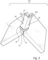
Fig. 3 is a schematic perspective view of a panel unit according to the first aspect of the present invention, comprising two panel members as shown inFig. 1 and a connecting element as shown inFig. 2 . -
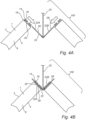
Fig. 4A is a schematic side view of the assembling of the panel unit inFig. 3 . -
Fig. 4B is a schematic side view of the panel unit inFig. 4A when in a suspended state. -
Fig. 5A is a schematic side view of the assembling a panel unit according to the first aspect of the present invention, wherein the panel members are provided with a respective at least one connector arranged on a respective main surface thereof. -
Fig. 5B is a schematic side view of the panel unit inFig. 5A when in a suspended state. -
Fig. 6 is a schematic side view of a panel unit according to the first aspect of the present invention wherein, in the suspended state, a side surface of one panel member is arranged against a portion of a main surface of the other panel member. - In the following detailed description, some embodiments of the present invention will be described. However, it is to be understood that features of the different embodiments are exchangeable between the embodiments and may be combined in different ways, unless anything is specifically indicated. Even though in the following description, numerous details are set forth to provide a more thorough understanding of the present invention, it will be apparent to one skilled in the art that the present invention may be practiced without these details. In other instances, well known constructions or functions are not described in detail, so as not to obscure the present invention.
- In
Fig. 1 ,Fig. 2 andFig. 3 , apanel member 1, a connectingelement 22 and apanel unit 100 assembled from twopanel members 1 and a connectingelement 22 are shown, respectively. InFig. 1 , thepanel member 1 is provided as a rectangular panel comprising a firstmain side surface 2, a secondmain side surface 4, afirst side surface 6, asecond side surface 8, athird side surface 10 and afourth side surface 12. However, it is to be understood that thepanel member 1 may have any suitable shape. For example, thepanel member 1 may be shaped as a half-disc or a polygon. Thepanel member 1 may be made of any suitable lightweight material. Preferably, thepanel member 1 is made of mineral wool, or a combination of mineral wool and further material, such as further mineral fiber material.. Furthermore, thepanel member 1 may be provided with a surface finish in the form of an exterior surface material, such as a non-woven or fabric facing. To this end, one or more main side surface and/or one or more side surface of thepanel member 1 may be provided as an exterior surface material. Furthermore, thepanel member 1 may comprise reinforcing material for improving the mechanical properties of thepanel member 1. For example, thepanel member 1 may be provided with at least one reinforcement member of a metal material. - The
panel member 1 is further provided with aconnector 14. InFig. 1 , theconnector 14 is further displayed independently and in greater detail. Theconnector 14 comprises ashaft 16 with afirst end 16A and an opposingsecond end 16B. Theconnector 14 further comprises ahead portion 18 arranged at thefirst end 16A, wherein thesecond end 16B is fixed to thepanel member 1 such that theshaft 16 extends from a surface of thepanel member 1 with thehead portion 18 arranged at a distance from the surface. Here, theconnector 14 is fixed to and extends from thesecond side surface 8 of thepanel member 1. Theconnector 14 may be fixed to thepanel member 1 in a variety of ways. For example, theconnector 14 may be readily inserted into thepanel member 1 such that theshaft 16 is at least partially embedded in thepanel member 1. - Further, in
Fig. 1 , thepanel member 1 is provided with fourconnectors 14 arranged in pairs. Here, each pair ofconnectors 14 is arranged on arespective disk 20 such that they may be fixed to thepanel member 1 in a leveled way. Here, theconnectors 14 are fixed to thepanel member 1 via therespective disk 20. To this end, eachdisk 20 may e.g. be provided with an anchoring portion, such as a screw or spiral. Alternatively, eachdisk 20 may be provided with one or more through-holes for receiving a screw, spiral, nail, or other fastening element. - The
connectors 14 and thedisks 20 may e.g. be made of metal, wood, or a hard plastic material. For example, eachconnector 14 may be made of the same material as therespective panel member 1. Moreover, theconnectors 14 and thepanel members 1 may alternatively be provided as a coherent unit. - In
Fig. 2 , a connectingelement 22 for suspension of the panel unit and for angled connection of a first and asecond panel member 1 to each other is shown. - The connecting
element 22 may e.g. be made of metal, wood, or a hard plastic material. The connectingelement 22 comprises a first and asecond leg element 22 is configured such that the first andsecond leg panel unit 100. The angle between thefirst leg 22A and thesecond leg 22B may be any angle between 180° and 0°. For example, the angle may be 30°, or 40°, or 50°, or 60°, or 70°, or 80°, or 90°, or 100°, or 110°, or 120°, or 130°. - Furthermore, each of the first and
second leg groove 24. Here, each of the first andsecond leg grooves 24 each. Eachgroove 24 is extending in a leg direction associated with the respective first andsecond leg groove 24 extend obliquely upwards in a suspended state of thepanel unit 100. Furthermore, eachgroove 24 is configured to receive arespective connector 14 of apanel member 1 such that thehead portion 18 of theconnector 14 engages an upwardly facingsurface respective leg panel unit 100. - Although not shown in
Fig. 2 , eachgroove 24 may be tapered in the leg direction associated with the respective first andsecond leg groove 24 is configured to wedgingly engage therespective shaft 16 of arespective connector 14. - Here, each
groove 24 is provided with aninlet 30 accessible from anedge surface 32 of thefirst leg 22A or thesecond leg 22B such that eachgroove 24 is configured to receive arespective connector 14 in a direction along the leg direction of the respectivefirst leg 22A orsecond leg 22B. Thus, eachgroove 24 is open-ended. Alternatively, eachgroove 24 may be provided with an inlet accessible from aside surface first leg 22A or thesecond leg 22B. InFig. 2 , theside surface 34 of thefirst leg 22A is arranged on an opposite side of the connectingunit 22 as the upward facingsurface 26, and theside surface 36 of thesecond leg 22A is arranged on an opposite side of the connectingunit 22 as the upward facingsurface 28. Hereby, eachgroove 24 is configured to receive arespective connector 14 in a direction transverse to the leg direction of the respectivefirst leg 22A orsecond leg 22B. Such an inlet may e.g. be provided as a widening of thegroove 24. To this end, eachgroove 24 may for example be substantially keyhole shaped. - The length of the
first leg 22A is inFig. 2 the same as thesecond leg 22B. Alternatively, the first and thesecond leg first leg 22A in the associated leg direction may be greater than a length of thesecond leg 22B in the associated leg direction. Moreover, the length of eachgroove 24 of thefirst leg 22A is inFig. 2 the same as the length of eachgroove 24 thesecond leg 22B. Alternatively, a length of eachgroove 24 of thefirst leg 22A may be greater than a length of eachgroove 22 of thesecond leg 22B. Moreover, the length of any onegroove 24 may differ from the length of anyother groove 24. - In
Fig. 3 , apanel unit 100 comprising twopanel members 1 and a connectingelement 22. Here, thepanel unit 100 is in a suspended state wherein eachhead portion 18 of eachrespective connector 14 engages an upwardly facingsurface respective leg Fig. 1 , theconnectors 14 are arranged in pairs oriented such that bothconnectors 14 of a pair ofconnectors 14 is arranged in thesame groove 24. However, the pair ofconnectors 14 may alternatively be oriented such that theconnectors 14 of a pair ofconnectors 14 are arranged indifferent grooves 24. - Furthermore, due to the orientation of the
grooves 24 in the suspended state of thepanel unit 100, a gravitationally assisted connection between the connectingelement 22 and thepanel members 1 is achieved. - In
Figs. 1 ,2 and3 , eachconnector 14 is provided on arespective side surface respective panel member 1. This arrangement is further illustrated from a side view inFig. 4A and Fig. 4B . InFig. 4A , assembly of thepanel unit 100 by insertion of theconnectors 14 in thegrooves 24 of the connectingelement 22 is illustrated. The direction of insertion is indicated by the arrows. Furthermore, the connectingelement 22 is here provided with asuspension unit 32 for suspending thepanel unit 100 to a structural ceiling, roof, beam, etc. InFig. 4B , the assembledpanel unit 100 is shown. - The at least one
connector 14 may alternatively be provided on any other surface of therespective panel member 1. For example, the at least oneconnector 14 may be provided on a respective main surface of thepanel members 1. This is illustrated inFig. 5A and Fig. 5B . This way, an alternative arrangement of thepanel members 1 in thepanel unit 100 is provided. Hereby, by varying the placement of theconnectors 14, different shapes of thepanel unit 100, e.g. corresponding to different demands on acoustical properties and/or visual appearance may be provided. - The at least one
connector 14 of afirst panel member 1 may further be arranged at a relative positive different than the at least oneconnector 14 of asecond panel member 1. An exemplary embodiment of this is illustrated inFig. 6 , wherein theconnectors 14 of afirst panel member 1 is arranged closer to alower side surface 8 of saidpanel member 1 compared to theconnectors 14 of thesecond panel member 1. Hereby, thesecond panel member 1 is arranged at a position lower than thefirst panel member 1, such that aside surface 8 of the first panel member is arranged against a portion of amain surface 2 of thesecond panel member 1. - It is to be understood that this may also be achieved by, or in conjunction with, the
respective grooves 24 of therespective leg groove 24 of thefirst leg 22A, a proportion of a length of thegroove 24 to a length of thefirst leg 22A being greater than a proportion of a length of eachgroove 24 of thesecond leg 22B to a length of thesecond leg 22B.
Claims (9)
- Panel unit for a suspended ceiling, the panel unit comprising:a first and second panel member, each of the first and a second panel member being provided with a respective at least one connector, each connector comprising a shaft with a first end and an opposing second end, and a head portion arranged at the first end, wherein the second end is fixed to the respective panel member such that the shaft extends from a surface of the panel member with the head portion arranged at a distance from the surface; anda connecting element for suspension of the panel unit and for angled connection of the first and second panel member to each other, the connecting element comprising a first and a second leg connected to each other in an angled relationship for forming a V-shaped structure, the connecting element being configured such that the first and second leg extend obliquely upwards in a suspended state of the panel unit;wherein each of the first and second leg is provided with a groove extending in a leg direction associated with the respective first and second leg, and wherein each groove is configured to receive a respective connector such that the head portion engages an upwardly facing surface of the leg in the suspended state of the panel unit.
- The panel unit according to claim 1, wherein each of the first and second panel member is provided with two respective connectors, and wherein each groove of the first and second leg is configured to receive the two respective connectors of a respective panel member.
- The panel unit according to claim 1, wherein each of the first and second panel member is provided with two respective connectors, wherein each of the first and second leg is provided with two respective grooves, and wherein each groove of the first and second leg is configured to receive a respective connector.
- The panel unit according to any preceding claim, wherein each groove is tapered in the leg direction associated with the respective first and second leg.
- The panel unit according to any preceding claim, wherein each groove is provided with an inlet accessible from an edge surface of the first leg or the second leg such that each groove is configured to receive a respective connector in a direction along the leg direction of the respective first leg or second leg.
- The panel unit according to any one of claims 1-4, wherein each groove is provided with an inlet accessible from a side surface of the first leg or the second leg such that each groove is configured to receive a respective connector in a direction transverse to the leg direction of the respective first leg or second leg.
- The panel unit according to any preceding claim, wherein a length of the first leg in the associated leg direction is greater than a length of the second leg in the associated leg direction.
- The panel unit according to any preceding claim, wherein a length of each groove of the first leg is greater than a length of each groove of the second leg.
- The panel unit according to any preceding claim, wherein for each groove of the first leg, a proportion of a length of the groove to a length of the first leg is greater than a proportion of a length of each groove of the second leg to a length of the second leg.
Priority Applications (2)
| Application Number | Priority Date | Filing Date | Title |
|---|---|---|---|
| EP22207410.6A EP4372172B1 (en) | 2022-11-15 | 2022-11-15 | Panel unit for suspended ceiling |
| PCT/EP2023/079787 WO2024104747A1 (en) | 2022-11-15 | 2023-10-25 | Panel unit for suspended ceiling |
Applications Claiming Priority (1)
| Application Number | Priority Date | Filing Date | Title |
|---|---|---|---|
| EP22207410.6A EP4372172B1 (en) | 2022-11-15 | 2022-11-15 | Panel unit for suspended ceiling |
Publications (3)
| Publication Number | Publication Date |
|---|---|
| EP4372172A1 true EP4372172A1 (en) | 2024-05-22 |
| EP4372172B1 EP4372172B1 (en) | 2025-08-27 |
| EP4372172C0 EP4372172C0 (en) | 2025-08-27 |
Family
ID=84358190
Family Applications (1)
| Application Number | Title | Priority Date | Filing Date |
|---|---|---|---|
| EP22207410.6A Active EP4372172B1 (en) | 2022-11-15 | 2022-11-15 | Panel unit for suspended ceiling |
Country Status (2)
| Country | Link |
|---|---|
| EP (1) | EP4372172B1 (en) |
| WO (1) | WO2024104747A1 (en) |
Citations (6)
| Publication number | Priority date | Publication date | Assignee | Title |
|---|---|---|---|---|
| US2689026A (en) * | 1949-10-18 | 1954-09-14 | Neo Ray Products Inc | Louvered ceiling construction with interengaging louver units and side rails |
| FR1203140A (en) * | 1958-07-22 | 1960-01-15 | Profil Sa Ind Financ Le | New profile for the removable fixing of sheets, sheets adapted to this profile and sets obtained by their combination |
| FR2483984A1 (en) * | 1980-06-10 | 1981-12-11 | Durlumen Sarl Ets | Backing strip for reflector - has curved profiled aluminium strip with rectilinear cross section |
| US5008791A (en) * | 1990-07-19 | 1991-04-16 | Caferro Ronald N | Low direct glare and wall wash parabolic lighting grid |
| US20080307724A1 (en) * | 2007-05-24 | 2008-12-18 | Eric Krantz-Lilienthal | Linking kit for panel structures |
| CN208650379U (en) * | 2018-07-09 | 2019-03-26 | 张默良 | A kind of ceiling hanging code |
Family Cites Families (1)
| Publication number | Priority date | Publication date | Assignee | Title |
|---|---|---|---|---|
| FR2892435B1 (en) * | 2005-10-26 | 2009-02-27 | Chenel Guy G | OPEN COVERED FLOOR ELEMENT, MANUFACTURING METHOD AND TEMPORARY CEILING MADE OF SUCH ELEMENTS |
-
2022
- 2022-11-15 EP EP22207410.6A patent/EP4372172B1/en active Active
-
2023
- 2023-10-25 WO PCT/EP2023/079787 patent/WO2024104747A1/en not_active Ceased
Patent Citations (6)
| Publication number | Priority date | Publication date | Assignee | Title |
|---|---|---|---|---|
| US2689026A (en) * | 1949-10-18 | 1954-09-14 | Neo Ray Products Inc | Louvered ceiling construction with interengaging louver units and side rails |
| FR1203140A (en) * | 1958-07-22 | 1960-01-15 | Profil Sa Ind Financ Le | New profile for the removable fixing of sheets, sheets adapted to this profile and sets obtained by their combination |
| FR2483984A1 (en) * | 1980-06-10 | 1981-12-11 | Durlumen Sarl Ets | Backing strip for reflector - has curved profiled aluminium strip with rectilinear cross section |
| US5008791A (en) * | 1990-07-19 | 1991-04-16 | Caferro Ronald N | Low direct glare and wall wash parabolic lighting grid |
| US20080307724A1 (en) * | 2007-05-24 | 2008-12-18 | Eric Krantz-Lilienthal | Linking kit for panel structures |
| CN208650379U (en) * | 2018-07-09 | 2019-03-26 | 张默良 | A kind of ceiling hanging code |
Also Published As
| Publication number | Publication date |
|---|---|
| EP4372172B1 (en) | 2025-08-27 |
| WO2024104747A1 (en) | 2024-05-23 |
| EP4372172C0 (en) | 2025-08-27 |
Similar Documents
| Publication | Publication Date | Title |
|---|---|---|
| CA2942452C (en) | Slide clip connector | |
| JP5745430B2 (en) | Mounting clip | |
| US7681370B2 (en) | Suspension systems | |
| US11946250B2 (en) | Ceiling system and method of installation | |
| KR20010033085A (en) | Drywall suspension grid system | |
| WO2008082868A2 (en) | Suspended ceiling system | |
| KR102417604B1 (en) | Seismic reinforcement type ceiling finishing apparatus | |
| US20250314065A1 (en) | Ceiling system and method of installation | |
| WO2018113908A1 (en) | Panels, mounting clamps and wall or ceiling covering for a 3-dimensional pattern of wall- and ceiling panels | |
| EP4372172B1 (en) | Panel unit for suspended ceiling | |
| JP2020139313A (en) | Ceiling panel | |
| WO2025088008A1 (en) | System for the construction of a sound insulation element, connecting elements for connecting of profile-elements of a sound insulation element and connector for connecting a support profile to at least one profile element of a sound insulation element | |
| JP7858191B2 (en) | Ceiling frame connecting structure | |
| JP2013036314A (en) | Joint metal of cradling material or the like | |
| JP6545220B2 (en) | Ceiling foundation structure and construction method of ceiling foundation structure | |
| EP1425482A1 (en) | Decorative structure and ceiling system | |
| KR102774374B1 (en) | Bracket for installing modular panels | |
| JP6888805B2 (en) | Connecting bracket and ceiling structure | |
| KR102940294B1 (en) | Acoustic click louver system | |
| JP6830033B2 (en) | Ceiling structure and construction method | |
| JP2021134487A (en) | Ceiling substrate structure and construction method of building | |
| KR20260064136A (en) | Acoustic Louver and Acoustic Louver Fastening System for Installing the Same | |
| US10640974B2 (en) | Surface forming system | |
| CA3049024C (en) | Drift clip | |
| KR20260064137A (en) | Acoustic Louver Fastening System |
Legal Events
| Date | Code | Title | Description |
|---|---|---|---|
| PUAI | Public reference made under article 153(3) epc to a published international application that has entered the european phase |
Free format text: ORIGINAL CODE: 0009012 |
|
| STAA | Information on the status of an ep patent application or granted ep patent |
Free format text: STATUS: THE APPLICATION HAS BEEN PUBLISHED |
|
| AK | Designated contracting states |
Kind code of ref document: A1 Designated state(s): AL AT BE BG CH CY CZ DE DK EE ES FI FR GB GR HR HU IE IS IT LI LT LU LV MC ME MK MT NL NO PL PT RO RS SE SI SK SM TR |
|
| STAA | Information on the status of an ep patent application or granted ep patent |
Free format text: STATUS: REQUEST FOR EXAMINATION WAS MADE |
|
| 17P | Request for examination filed |
Effective date: 20241122 |
|
| RBV | Designated contracting states (corrected) |
Designated state(s): AL AT BE BG CH CY CZ DE DK EE ES FI FR GB GR HR HU IE IS IT LI LT LU LV MC ME MK MT NL NO PL PT RO RS SE SI SK SM TR |
|
| GRAP | Despatch of communication of intention to grant a patent |
Free format text: ORIGINAL CODE: EPIDOSNIGR1 |
|
| STAA | Information on the status of an ep patent application or granted ep patent |
Free format text: STATUS: GRANT OF PATENT IS INTENDED |
|
| INTG | Intention to grant announced |
Effective date: 20250414 |
|
| GRAS | Grant fee paid |
Free format text: ORIGINAL CODE: EPIDOSNIGR3 |
|
| GRAA | (expected) grant |
Free format text: ORIGINAL CODE: 0009210 |
|
| STAA | Information on the status of an ep patent application or granted ep patent |
Free format text: STATUS: THE PATENT HAS BEEN GRANTED |
|
| AK | Designated contracting states |
Kind code of ref document: B1 Designated state(s): AL AT BE BG CH CY CZ DE DK EE ES FI FR GB GR HR HU IE IS IT LI LT LU LV MC ME MK MT NL NO PL PT RO RS SE SI SK SM TR |
|
| REG | Reference to a national code |
Ref country code: CH Ref legal event code: EP |
|
| REG | Reference to a national code |
Ref country code: DE Ref legal event code: R096 Ref document number: 602022020158 Country of ref document: DE |
|
| REG | Reference to a national code |
Ref country code: IE Ref legal event code: FG4D |
|
| U01 | Request for unitary effect filed |
Effective date: 20250923 |
|
| U07 | Unitary effect registered |
Designated state(s): AT BE BG DE DK EE FI FR IT LT LU LV MT NL PT RO SE SI Effective date: 20251001 |
|
| U20 | Renewal fee for the european patent with unitary effect paid |
Year of fee payment: 4 Effective date: 20251016 |
|
| PG25 | Lapsed in a contracting state [announced via postgrant information from national office to epo] |
Ref country code: IS Free format text: LAPSE BECAUSE OF FAILURE TO SUBMIT A TRANSLATION OF THE DESCRIPTION OR TO PAY THE FEE WITHIN THE PRESCRIBED TIME-LIMIT Effective date: 20251227 |
|
| PG25 | Lapsed in a contracting state [announced via postgrant information from national office to epo] |
Ref country code: NO Free format text: LAPSE BECAUSE OF FAILURE TO SUBMIT A TRANSLATION OF THE DESCRIPTION OR TO PAY THE FEE WITHIN THE PRESCRIBED TIME-LIMIT Effective date: 20251127 |
|
| PG25 | Lapsed in a contracting state [announced via postgrant information from national office to epo] |
Ref country code: HR Free format text: LAPSE BECAUSE OF FAILURE TO SUBMIT A TRANSLATION OF THE DESCRIPTION OR TO PAY THE FEE WITHIN THE PRESCRIBED TIME-LIMIT Effective date: 20250827 |
|
| PG25 | Lapsed in a contracting state [announced via postgrant information from national office to epo] |
Ref country code: GR Free format text: LAPSE BECAUSE OF FAILURE TO SUBMIT A TRANSLATION OF THE DESCRIPTION OR TO PAY THE FEE WITHIN THE PRESCRIBED TIME-LIMIT Effective date: 20251128 |
|
| PG25 | Lapsed in a contracting state [announced via postgrant information from national office to epo] |
Ref country code: PL Free format text: LAPSE BECAUSE OF FAILURE TO SUBMIT A TRANSLATION OF THE DESCRIPTION OR TO PAY THE FEE WITHIN THE PRESCRIBED TIME-LIMIT Effective date: 20250827 |
|
| PG25 | Lapsed in a contracting state [announced via postgrant information from national office to epo] |
Ref country code: RS Free format text: LAPSE BECAUSE OF FAILURE TO SUBMIT A TRANSLATION OF THE DESCRIPTION OR TO PAY THE FEE WITHIN THE PRESCRIBED TIME-LIMIT Effective date: 20251127 |
|
| PG25 | Lapsed in a contracting state [announced via postgrant information from national office to epo] |
Ref country code: ES Free format text: LAPSE BECAUSE OF FAILURE TO SUBMIT A TRANSLATION OF THE DESCRIPTION OR TO PAY THE FEE WITHIN THE PRESCRIBED TIME-LIMIT Effective date: 20250827 |
|
| PG25 | Lapsed in a contracting state [announced via postgrant information from national office to epo] |
Ref country code: SM Free format text: LAPSE BECAUSE OF FAILURE TO SUBMIT A TRANSLATION OF THE DESCRIPTION OR TO PAY THE FEE WITHIN THE PRESCRIBED TIME-LIMIT Effective date: 20250827 |
|
| PG25 | Lapsed in a contracting state [announced via postgrant information from national office to epo] |
Ref country code: CZ Free format text: LAPSE BECAUSE OF FAILURE TO SUBMIT A TRANSLATION OF THE DESCRIPTION OR TO PAY THE FEE WITHIN THE PRESCRIBED TIME-LIMIT Effective date: 20250827 |
|
| PG25 | Lapsed in a contracting state [announced via postgrant information from national office to epo] |
Ref country code: SK Free format text: LAPSE BECAUSE OF FAILURE TO SUBMIT A TRANSLATION OF THE DESCRIPTION OR TO PAY THE FEE WITHIN THE PRESCRIBED TIME-LIMIT Effective date: 20250827 |
|
| REG | Reference to a national code |
Ref country code: CH Ref legal event code: H13 Free format text: ST27 STATUS EVENT CODE: U-0-0-H10-H13 (AS PROVIDED BY THE NATIONAL OFFICE) Effective date: 20260623 |
|
| PG25 | Lapsed in a contracting state [announced via postgrant information from national office to epo] |
Ref country code: MC Free format text: LAPSE BECAUSE OF FAILURE TO SUBMIT A TRANSLATION OF THE DESCRIPTION OR TO PAY THE FEE WITHIN THE PRESCRIBED TIME-LIMIT Effective date: 20250827 |
|
| PLBE | No opposition filed within time limit |
Free format text: ORIGINAL CODE: 0009261 |
|
| STAA | Information on the status of an ep patent application or granted ep patent |
Free format text: STATUS: NO OPPOSITION FILED WITHIN TIME LIMIT |
|
| REG | Reference to a national code |
Ref country code: CH Ref legal event code: L10 Free format text: ST27 STATUS EVENT CODE: U-0-0-L10-L00 (AS PROVIDED BY THE NATIONAL OFFICE) Effective date: 20260708 |
|
| PG25 | Lapsed in a contracting state [announced via postgrant information from national office to epo] |
Ref country code: CH Free format text: LAPSE BECAUSE OF NON-PAYMENT OF DUE FEES Effective date: 20251130 |
|
| 26N | No opposition filed |
Effective date: 20260528 |