EP4372151B1 - Gate water supplement device - Google Patents
Gate water supplement device Download PDFInfo
- Publication number
- EP4372151B1 EP4372151B1 EP23158748.6A EP23158748A EP4372151B1 EP 4372151 B1 EP4372151 B1 EP 4372151B1 EP 23158748 A EP23158748 A EP 23158748A EP 4372151 B1 EP4372151 B1 EP 4372151B1
- Authority
- EP
- European Patent Office
- Prior art keywords
- contactor
- water supplement
- power supply
- gate
- opening
- Prior art date
- Legal status (The legal status is an assumption and is not a legal conclusion. Google has not performed a legal analysis and makes no representation as to the accuracy of the status listed.)
- Active
Links
Images



Classifications
-
- G—PHYSICS
- G01—MEASURING; TESTING
- G01L—MEASURING FORCE, STRESS, TORQUE, WORK, MECHANICAL POWER, MECHANICAL EFFICIENCY, OR FLUID PRESSURE
- G01L11/00—Measuring steady or quasi-steady pressure of a fluid or a fluent solid material by means not provided for in group G01L7/00 or G01L9/00
-
- E—FIXED CONSTRUCTIONS
- E02—HYDRAULIC ENGINEERING; FOUNDATIONS; SOIL SHIFTING
- E02B—HYDRAULIC ENGINEERING
- E02B8/00—Details of barrages or weirs ; Energy dissipating devices carried by lock or dry-dock gates
- E02B8/04—Valves, slides, or the like; Arrangements therefor; Submerged sluice gates
-
- E—FIXED CONSTRUCTIONS
- E02—HYDRAULIC ENGINEERING; FOUNDATIONS; SOIL SHIFTING
- E02B—HYDRAULIC ENGINEERING
- E02B7/00—Barrages or weirs; Layout, construction, methods of, or devices for, making same
- E02B7/20—Movable barrages; Lock or dry-dock gates
- E02B7/26—Vertical-lift gates
-
- E—FIXED CONSTRUCTIONS
- E02—HYDRAULIC ENGINEERING; FOUNDATIONS; SOIL SHIFTING
- E02B—HYDRAULIC ENGINEERING
- E02B7/00—Barrages or weirs; Layout, construction, methods of, or devices for, making same
- E02B7/20—Movable barrages; Lock or dry-dock gates
- E02B7/26—Vertical-lift gates
- E02B7/28—Vertical-lift gates with sliding gates
-
- E—FIXED CONSTRUCTIONS
- E02—HYDRAULIC ENGINEERING; FOUNDATIONS; SOIL SHIFTING
- E02B—HYDRAULIC ENGINEERING
- E02B7/00—Barrages or weirs; Layout, construction, methods of, or devices for, making same
- E02B7/20—Movable barrages; Lock or dry-dock gates
- E02B7/26—Vertical-lift gates
- E02B7/36—Elevating mechanisms for vertical-lift gates
-
- G—PHYSICS
- G05—CONTROLLING; REGULATING
- G05D—SYSTEMS FOR CONTROLLING OR REGULATING NON-ELECTRIC VARIABLES
- G05D9/00—Level control, e.g. controlling quantity of material stored in vessel
- G05D9/12—Level control, e.g. controlling quantity of material stored in vessel characterised by the use of electric means
-
- Y—GENERAL TAGGING OF NEW TECHNOLOGICAL DEVELOPMENTS; GENERAL TAGGING OF CROSS-SECTIONAL TECHNOLOGIES SPANNING OVER SEVERAL SECTIONS OF THE IPC; TECHNICAL SUBJECTS COVERED BY FORMER USPC CROSS-REFERENCE ART COLLECTIONS [XRACs] AND DIGESTS
- Y02—TECHNOLOGIES OR APPLICATIONS FOR MITIGATION OR ADAPTATION AGAINST CLIMATE CHANGE
- Y02E—REDUCTION OF GREENHOUSE GAS [GHG] EMISSIONS, RELATED TO ENERGY GENERATION, TRANSMISSION OR DISTRIBUTION
- Y02E10/00—Energy generation through renewable energy sources
- Y02E10/20—Hydro energy
Definitions
- the present disclosure relates to the technical field of water conservancy and hydropower projects, and the invention is directed towards a gate water supplement device.
- Lowering gate and starting reservoir impoundment of hydropower station project are major nodes of the project, and the generator unit can only be commissioned and operated after the impoundment has been finished.
- the gate lowering of the hydropower station project is to lower the blocking gate of the diversion tunnel for temporarily passing water during the construction period. After the gate is lowered, the downstream river channel of the project may be temporarily cut off before the reservoir water level rises to the point where the flood release structures of the hydropower station hub can discharge, which has a great impact on the downstream river channel ecology.
- Document KR 101 230 778 B1 discloses an example of a gate water supplement device. Therefore, at the beginning of the design of the hydropower station project, the relevant measures of water supplement to the downstream ecology will be considered simultaneously during the gate lowering period. At present, it is generally adopted to arrange special ecological water supplement channel and so on, which has the problems of large resource investment and inaccurate control.
- the technical problem to be solved by the present invention is to overcome that arranging special ecological water supplement channel requires more resources and the control is not accurate enough at the beginning of the design of the hydropower station project in the prior art, so as to provide a gate water supplement device.
- a gate water supplement device comprising:
- the contactor member comprises a signal terminal and a power supply terminal;
- the contactor frame is provided with a signal contactor and a power supply contactor adapted to the contactor member, the signal contactor is plugged with the signal terminal, and the power supply contactor is plugged with the power supply terminal.
- the signal terminal and the power supply terminal are both conical opening structure
- the signal contactor of the contactor frame extends into the opening of the signal terminal
- the power supply contactor extends into the opening of the power supply terminal
- the contactor frame is an arch structure
- a power supply line and a signal line are connected between the contactor frame and the controller, the power supply line and the signal line are connected between the contactor member and the opening and closing member.
- an insulating pad is arranged between the signal terminal and the power supply terminal.
- the gate water supplement device further comprises a tube body arranged in the dam body, wherein a line between the contactor frame and the controller is arranged in the tube body, and the contactor frame is at least partially arranged in the tube body.
- an elastic member is arranged between the contactor frame and the tube body, and the elastic member is in a compressed state when the contactor frame is not in contact with the contactor member.
- the end of the tube body towards the gate body is provided with a sealing cover plate which is communicated with the controller through signal.
- the number of the opening and closing member in the ecological water supplement channel is at least two, and each opening and closing member is connected with the power supply line and the signal line.
- the water inlet of the ecological water supplement channel is also provided with a slag blocking grille.
- orientations or position relationships indicated by the terms “center”, “top”, “bottom”, “left”, “right”, “vertical”, “horizontal”, “inside”, “outside”, etc. are based on the orientation or position relationship shown in the drawings, only used for the convenience of describing the present invention and simplifying the description, rather than indicating or implying that the device or element referred to must have a specific orientation, be constructed and operated in a specific orientation, and therefore cannot be understood as a limitation of the present invention.
- first”, “second” and “third” are only used for descriptive purposes and cannot be understood as indicating or implying relative importance.
- connection should be understood in a broad sense, for example, they can be fixed connection, detachable connection or integrated connection; they can be mechanical connection or electrical connection; they can be direct connection, or indirect connection through intermediate media, they can be the internal communication between two elements.
- connection should be understood in a broad sense, for example, they can be fixed connection, detachable connection or integrated connection; they can be mechanical connection or electrical connection; they can be direct connection, or indirect connection through intermediate media, they can be the internal communication between two elements.
- connection should be fixed connection, detachable connection or integrated connection; they can be mechanical connection or electrical connection; they can be direct connection, or indirect connection through intermediate media, they can be the internal communication between two elements.
- the present invention provides a gate water supplement device, comprising: a gate body 2 configured to be arranged in a dam body 1, wherein a lower part 16 of the gate body 2 is provided with an ecological water supplement channel 23, an opening and closing member is provided in the ecological water supplement channel 23, the downstream surface of the gate body 2 is provided with a contactor frame 7 which is communicated with the opening and closing member through lines; a control structure configured to be arranged in the dam body 1, wherein the control structure comprises a controller 15 and a contactor frame 7 arranged towards the downstream surface, the controller 15 is communicated with the contactor frame 7 through lines, after the gate body 2 falls to a predetermined position, the contactor frame 7 is in contact with the contactor member 18, the controller 15 controls the opening or closing of the opening and closing member through lines to control the water flow in the ecological water supplement channel 23.
- the lower part 16 of the gate body 2 is provided with an ecological water supplement channel 23, the gate body is provided with an ecological water supplement channel 23, and it is not necessary to build special ecological water supplement channel and opening and closing member during the design and construction stages, which can save resources, use one thing for multiple purposes, and improve the efficiency of water supplement.
- the downstream face of the gate body 2 is provided with a contactor member 18, and the control structure is provided with a contactor member 18 towards the downstream face.
- a specific embodiment of the gate water supplement device comprises: a dam body 1 provided with gate body and diversion tunnel 8, wherein the gate body 2 rises and falls along the guide groove 13 of the dam body 1; and a control structure arranged in the dam body 1.
- the lift and fall of the gate body 2 is controlled by the elevator 14 at the top of dam body 1.
- the lower part 16 of the gate body 2 is provided with an ecological water supplement channel 23, that is, the ecological water supplement channel 23 passes through the gate body.
- the ecological water supplement channel 23 is provided with a first opening and closing member 5 and a second opening and closing member 6.
- the first opening and closing member 5 and the second opening and closing member 6 are valves. It should be noted that the first opening and closing member 5 and the second opening and closing member 6 can be opened or closed by manual adjustment under the extreme state of power failure.
- the water inlet of the ecological water supplement channel 23 is also provided with a slag blocking grille 4, a contactor member 18 is arranged on the downstream face of the gate body to correspond with the diversion tunnel 8.
- the contactor member 18 is provided with a signal guide groove and a power supply guide groove along the height direction.
- the upper end of the signal guide groove is respectively provided with a signal terminal 19, and the upper end of the power supply guide groove is respectively provided with a power supply terminal 20, wherein the signal terminal 19 and the power supply terminal 20 are both conical opening structures.
- the upper openings of the signal terminal 19 at the upper end of the signal guide groove and the power supply terminal 20 at the upper end of the power supply guide groove are configured as a upward groove type.
- an insulating pad 17 is arranged between the signal terminal 19 and the power supply terminal 20. It should be noted that the height of the insulating pad is lower than the height of the water seal of the gate body 2, so as to avoid affecting the normal operation of the gate body 2.
- the signal terminal 19 is connected to the first opening and closing member 5 and the second opening and closing member 6 respectively through signal line 21
- the power supply terminal 20 are connected to the first opening and closing member 5 and the second opening and closing member 6 respectively through the power supply line 21, wherein the signal line 21 and power supply line 22 are both arranged in a protective tube 3.
- an insulating plate is arranged between signal line 21 and power supply line 22.
- a control structure is arranged in the dam body 1, wherein one end of the diversion tunnel 8 is provided with a controller 15, and the other end of the diversion tunnel 8 is provided with a contactor frame 7, that is, the contactor frame 7 is arranged towards the downstream face of the gate body 2.
- the gate water supplement device also comprises the line between the contactor frame 7 and the controller 15, as well as the tube body 11 which is sleeved around the line, wherein the tube body 11 is arranged in the diversion tunnel 8 to protect the line.
- the tube body 11 can be buried in the dam body 1 during the pouring process of the dam body 1, which is convenient and simple to set.
- the material of the tube body 11 is steel tube.
- the top of the tube body 11 is arranged with a water seal plate to prevent the water in the diversion tunnel 8 from entering the tube body 11.
- the line comprises signal line 21 and power supply line 22.
- the gate water supplement device further comprises an elastic member 12 arranged between the tube body 11 and the contactor frame 7.
- the structure of the contactor frame 7 is preferably arc-shaped structure.
- the elastic member 12 is a spring.
- the elastic member 12 drives the contactor frame 7 to move, so that the signal terminal 19 and the power supply terminal 20 of the contactor frame 7 enter the signal terminal 19 and the power supply terminal 20 along the configuration of the conical opening structure, realizing adaptive adjustment to solve the problem that the gate body 2 does not fall in place.
- a sealing cover plate 9 is arranged at one end of the tube body 11 towards the gate body 2, and the sealing cover plate 9 is connected to the controller 15 through signal.
- the sealing cover plate 9 is made of cork.
- the contactor frame 7 is provided with a signal contactor 24 adapted to the signal terminal 19 and a power supply contactor 25 adapted to the power supply terminal 20, wherein the signal contactor 24 is plugged with the signal terminal 19, and the power supply contact 25 is plugged with the power supply terminal 20.
- a clapboard groove 26 is arranged between the signal contactor 24 and the power supply contactor 25, that is, the "arch" contactor frame 7 can rotate around the clapboard groove 26 with hinge points, so that the signal contactor 24 can smoothly enter the signal terminal 19 and the power supply contact 25 can enter the power supply terminal 20, achieving accurate docking.
- a manhole 10 and an access cover plate used for the seal the manhole 10 are arranged on the side wall of tube body 11 close to gate body 2. The access cover plate is used to seal the manhole to avoid air leakage, water leakage and other problems.
- the gate body 2 is lifted and lowered by the elevator 14.
- the controller 15 controls the sealing end cover to be in a sealed state, that is, the contactor frame 7 is completely located in the tube body 11, and the elastic member 12 is in a compressed state simultaneously.
- the controller 15 opens the sealing cover plate 9, the elastic member 12 applies the force to the contactor frame 7 to move towards the gate body 2, the signal contactor 24 and the power supply contactor 25 of the contactor frame 7 move towards the gate body 2, and the signal contactor 24 enters the conical opening structure of the signal end 19 below the signal guide groove, and the power supply contactor 25 enters into the conical opening structure of the power supply terminal 20 below the power supply guide groove.
- the signal contactor 24 moves along the signal guide groove, and the power supply contactor 25 moves along the power supply guide groove until the gate body 2 drops to the predetermined position, the signal contactor 24 is successfully plugged into the signal terminal 19 above the signal guide groove, the power supply contactor 25 is successfully plugged into the power supply terminal 20 above the power supply guide groove, and meanwhile, the clapboard groove 26 is clamped into the insulating pad 17.
- the remote control room remotely controls the controller 15 according to the data of the water pressure detection probe. When water supplement is required, the controller 15 will send a signal to open the first opening and closing member 5 and the second opening and closing member 6 successively to supply water to the outside.
- the water flow can also be controlled through the first opening and closing member 5 and the second opening and closing member 6.
- the controller 15 sends a signal to close the first opening and closing member 5 and the second opening and closing member 6.
- the remote control function of the first opening and closing member 5 and the second opening and closing member 6 is damaged, if the first opening and closing member 5 and the second opening and closing member 6 need to be opened, the personnel will enter along the diversion tunnel 8 and open them manually after reaching the first opening and closing member 5 and the second opening and closing member 6.
- the manual control mode is only used as an emergency standby mode.
- the ecological water supplement channel 23 can also be provided with opening and closing member such as a third opening and closing member, a fourth opening and closing member and so on.
- the sealing cover plate 9 can also be made of plastic, steel plate and other materials.
- the sealing cover plate 9 when the sealing cover plate 9 is opened, the sealing cover plate 9 can be opened by pressurizing and blowing air from the air compressor into the tube body 11. When the pressure in the tube body reaches a preset value, the sealing cover plate 9 will be opened under pressure.
- the signal terminal 19 and the power supply terminal 20 can also be a horn-type opening structure, so as to facilitate accurate docking between the contactor and the contactor end.
- the dam body 1 in order to detect the water level and water pressure in the dam, is also provided with a water pressure detection probe and a remote control room, wherein the remote control room is respectively connected to the water pressure detection probe, the elevator 14 and the controller 15 through signal.
- the water pressure detection probe transmits the data to the remote control room.
- the remote control room sends instructions to the controller 15, and the opening and closing member is opened or closed through the controller 15 to achieve automatic control.
- this embodiment does not specifically define the connection mode between the signal contactor 24 and the signal terminal 19, and the connection mode between the power supply contactor 25 and the power supply terminal 20.
- the signal contactor 24 and the signal terminal 19, and the power supply contact 25 and the power supply terminal 20 can also be connected through wireless transmission communication respectively.
- the gate water supplement device provided by the present invention has the following advantages: (1) the way of arranging ecological water supplement holes on the gate body of the diversion tunnel is innovatively adopted, which solves the problem of large investment of resources and long-time consumption when side holes are separately dug or special ecological water supplement channel is set beside the diversion tunnel adopted in traditional ecological water supplement, and the continuity and convenience of ecological water supplement and gate lowering is guaranteed; (2), the problem that it is difficult to close the water supplement valve is solved and the risk that the valve of water supplement hole cannot be effectively closed is reduced through the unique structural configuration and the reliable configuration of "three in one" (remote control, water pressure detection control, manual control) for valve closure, and the safety and reliability of the operation of ecological water supplement hole are ensured; (3) high degree of automation: the water pressure is detected in real time by arranging a water pressure detection probe in the pipe of the water supplement hole, and the data is transmitted to the control switch connected to the opening and closing device of the control valve, and when the water pressure reaches the set value, the automatic closing is realized; (4) the device has
Landscapes
- Engineering & Computer Science (AREA)
- General Engineering & Computer Science (AREA)
- Structural Engineering (AREA)
- Mechanical Engineering (AREA)
- Civil Engineering (AREA)
- Physics & Mathematics (AREA)
- General Physics & Mathematics (AREA)
- Automation & Control Theory (AREA)
- Barrages (AREA)
Description
- The present disclosure relates to the technical field of water conservancy and hydropower projects, and the invention is directed towards a gate water supplement device.
- Lowering gate and starting reservoir impoundment of hydropower station project are major nodes of the project, and the generator unit can only be commissioned and operated after the impoundment has been finished. The gate lowering of the hydropower station project is to lower the blocking gate of the diversion tunnel for temporarily passing water during the construction period. After the gate is lowered, the downstream river channel of the project may be temporarily cut off before the reservoir water level rises to the point where the flood release structures of the hydropower station hub can discharge, which has a great impact on the downstream river channel ecology. Document
KR 101 230 778 B1 - Therefore, the technical problem to be solved by the present invention is to overcome that arranging special ecological water supplement channel requires more resources and the control is not accurate enough at the beginning of the design of the hydropower station project in the prior art, so as to provide a gate water supplement device.
- In order to solve the above-mentioned problems, the present invention provides a gate water supplement device according to
claim 1, comprising: - a gate body configured to be arranged in a dam body, wherein a lower part of the gate body is provided with an ecological water supplement channel, an opening and closing member is provided in the ecological water supplement channel, the downstream face of the gate body is provided with a contactor member which is communicated with the opening and closing member through lines;
- a control structure configured to be arranged in the dam body, wherein the control structure comprises a controller and a contactor frame arranged towards the downstream face, the controller is communicated with the contactor frame through lines, after the gate body falls to a predetermined position, the contactor frame is in contact with the contactor member, the controller controls the opening or closing of the opening and closing member through lines to control the water flow in the ecological water supplement channel.
- Optionally, the contactor member comprises a signal terminal and a power supply terminal; the contactor frame is provided with a signal contactor and a power supply contactor adapted to the contactor member, the signal contactor is plugged with the signal terminal, and the power supply contactor is plugged with the power supply terminal.
- Optionally, the signal terminal and the power supply terminal are both conical opening structure, the signal contactor of the contactor frame extends into the opening of the signal terminal, and the power supply contactor extends into the opening of the power supply terminal, the contactor frame is an arch structure.
- Optionally, a power supply line and a signal line are connected between the contactor frame and the controller, the power supply line and the signal line are connected between the contactor member and the opening and closing member.
- Optionally, an insulating pad is arranged between the signal terminal and the power supply terminal.
- Optionally, the gate water supplement device further comprises a tube body arranged in the dam body, wherein a line between the contactor frame and the controller is arranged in the tube body, and the contactor frame is at least partially arranged in the tube body.
- Optionally, an elastic member is arranged between the contactor frame and the tube body, and the elastic member is in a compressed state when the contactor frame is not in contact with the contactor member.
- Optionally, the end of the tube body towards the gate body is provided with a sealing cover plate which is communicated with the controller through signal.
- Optionally, the number of the opening and closing member in the ecological water supplement channel is at least two, and each opening and closing member is connected with the power supply line and the signal line.
- Optionally, the water inlet of the ecological water supplement channel is also provided with a slag blocking grille.
- The technical solution of the present invention has the following advantages:
- 1. The gate water supplement device provided in the present invention comprises: a gate body configured to be arranged in a dam body, wherein a lower part of the gate body is provided with an ecological water supplement channel, an opening and closing member is provided in the ecological water supplement channel, the downstream face of the gate body is provided with a contactor member which is communicated with the opening and closing member through lines; a control structure configured to be arranged in the dam body, wherein the control structure comprises a controller and a contactor frame arranged towards the downstream face, the controller is communicated with the contactor frame through lines, after the gate body falls to a predetermined position, the contactor frame is in contact with the contactor member, the controller controls the opening or closing of the opening and closing member through lines to control the water flow in the ecological water supplement channel. The lower part of the gate body is provided with an ecological water supplement channel, the gate body is provided with an ecological water supplement channel, and it is not necessary to build special ecological water supplement channel and opening and closing member in the dam body during the design and construction stages, which can save resources. Meanwhile, the downstream face of the gate body is provided with a contactor member, and the control structure is provided with a contactor member towards the downstream face. When the gate body falls to a predetermined position, the contactor frame contacts the contactor member to connect electrical signals or communication signals, and the controller controls the opening or closing of the opening and closing member to control the water flow in the ecological water supplement channel, which has the advantage of convenience and accuracy. The ecological water supplement problem of the downstream river channel during the period of lowering the gate can be completely solved and a large amount of resource investment can be saved by arranging an ecological water supplement channel on the gate body and ensuring that the gate can also be opened and closed normally after being lowered.
In contrast, after the gate is lowered, impoundment begins and the diversion tunnel is blocked, the opening and closing equipment of gate will also be submerged with the rise of the reservoir water level. Therefore, it is impossible to use its opening and closing equipment or its layout platform to arrange ecological water supplement control equipment, which has the problem of low reliability. In addition, if the water supplement hole fails to close or cannot be closed tightly, a large amount of leakage may occur under the high water head of the reservoir, affecting the safe operation of the project. Meanwhile, it will be very difficult to stop leakage under high water level, which will directly lead to the lagging process of reservoir water storage and even power generation, causing huge negative impacts and economic losses to the project. The gate water supplement device provided by the present invention overcomes the above mentioned problems and has the advantages of convenient opening and closing and accurate control. - 2. In the gate water supplement device provided in the present invention, the contactor member comprises a signal terminal and a power supply terminal; the contactor frame is provided with a signal contactor and a power supply contactor adapted to the contactor member, the signal contactor is plugged with the signal terminal, and the power supply contactor is plugged with the power supply terminal, so that the signal of the controller is transmitted to the signal terminal through the signal contactor and to the power supply terminal through the power supply contactor.
- 3. In the gate water supplement device provided in the present invention, the signal terminal and the power supply terminal are both conical opening structure, the signal contactor of the contactor frame extends into the opening of the signal terminal, and the power supply contactor extends into the opening of the power supply terminal. When the gate body is about to fall to the predetermined position, the signal contactor enters the conical opening structure of the signal terminal and the power supply contactor enters the conical opening structure of the power supply terminal until the gate body falls to the predetermined position. The configuration of conical opening structure is convenient for the signal contactor and power supply contactor to be accurately and reliably connected together during the connection process without poor contact due to position offset, so that the signal contactor and signal terminal, power supply contactor and power supply terminal can be better connected.
- 4. In the gate water supplement device provided in the present invention, a power supply line and a signal line are connected between the contactor frame and the controller, the power supply line and the signal line are connected between the contactor member and the opening and closing member, and the insulating plate is arranged between the power supply line and the signal line, power supply line transmits current, signal line transmits signal, and the arrangement of insulating plate avoids signal interference between power supply line and signal line.
- 5. In the gate water supplement device provided in the present invention, an insulating pad is arranged between the signal terminal and the power supply terminal, the insulating pad can avoid interference between current signal and communication signal, as well as conductive interference with the metal door body and influence on working effect.
- 6. The gate water supplement device provided in the present invention further comprises a tube body arranged in the dam body, since a line between the contactor frame and the controller is arranged in the tube body, and the contactor frame is at least partially arranged in the tube body, the tube body can also protect the lines between the contactor frame and the controller, as well as the contactor frame, and can also solve the problem that the contactor frame and the line pass through the dam structure.
- 7. In the gate water supplement device provided in the present invention, an elastic member is arranged between the contactor frame and the tube body, and the elastic member is in a compressed state when the contactor frame is not in contact with the contactor member. After the contactor frame is in contact with the contactor member, the compressed elastic member makes the contactor frame have the force to move towards the contactor member, so as to push the contactor frame to move towards the contactor member until the signal contactor of the contactor frame is successfully connected to the signal terminal, and the power supply contactor is successfully connected to the power supply terminal.
- 8. In the gate water supplement device provided in the present invention, the end of the tube body towards the gate body is provided with a sealing cover plate which is communicated with the controller through signal, the controller controls the opening or closing of the sealing cover plate to control the extension or retraction of the contactor frame.
- 9. In the gate water supplement device provided in the present invention, the number of the opening and closing member in the ecological water supplement channel is at least two, and each opening and closing member is connected to the power supply line and the signal line. Two or more opening and closing members play the role of backup to each other to avoid affecting the normal operation of the ecological water supplement channel due to problem with one of opening and closing members. The controller of the opening and closing members is arranged inside the gate to isolate the water upstream of the gate.
- 10. In the gate water supplement device provided in the present invention, the water inlet of the ecological water supplement channel is also provided with a slag blocking grille, the slag blocking grille can prevent fish and other organisms and pollutants in water from entering the ecological water supplement channel, so as to avoid affecting the operation of the ecological water supplement channel and the opening and closing of the opening and closing member.
- In order to more clearly explain the specific embodiments of the present invention or the technical solution in the prior art, the drawings needed in the specific embodiments or description of the prior art will be briefly introduced hereinafter. Obviously, the drawings in the following description are some embodiments of the present invention. For an ordinary person skilled in the art, he can also obtain other drawings based on these drawings without expenditure of any creative labor.
-
Figure 1 is the structural schematic diagram of the dam body and gate water supplement device provided in the embodiment of the present invention; -
Figure 2 is the structural schematic diagram of the dam body provided in the embodiment of the present invention; -
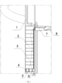
Figure 3 is the structural schematic diagram of position of tube body close to gate body provided in the embodiment of the present invention; -
Figure 4 is the side schematic diagram of the gate structure in the dam body provided in the embodiment of the present invention; -
Figure 5 is the structural schematic diagram of the ecological water supplement channel provided in the embodiment of the present invention; -
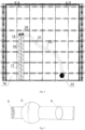
Figure 6 is the structural schematic diagram of the contactor member provided in the embodiment of the present invention; -
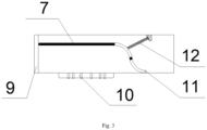
Figure 7 is the structural schematic diagram of the contactor frame provided in the embodiment of the present invention. - Reference numeral:
1. Dam body; 2. Gate body; 3.Protective tube 4. Slag blocking grille; 5. First opening and closing member; 6. Second opening and closing member; 7. Contactor frame; 8. Diversion tunnel; 9. Sealing cover plate; 10. Manhole; 11. Tube body; 12. Elastic member; 13. Guide groove; 14. Elevator; 15. Controller; 16. Lower part; 17. Insulating pad; 18. Contactor member; 19. Signal terminal; 20. Power supply terminal; 21. Signal line; 22. Power supply line; 23. Ecological water supplement channel; 24. Signal contactor; 25. Power supply contactor; 26. Clapboard groove. - The technical solution of the present invention will be described clearly and completely hereinafter in combination with the drawings. Obviously, the described embodiments are part of the embodiments of the present invention, not all of them. Based on the embodiments of the present invention, all other embodiments obtained by an ordinary person skilled in the art without expenditure of any creative work belong to the protection scope of the present invention.
- In the description of the present invention, it should be noted that the orientations or position relationships indicated by the terms "center", "top", "bottom", "left", "right", "vertical", "horizontal", "inside", "outside", etc. are based on the orientation or position relationship shown in the drawings, only used for the convenience of describing the present invention and simplifying the description, rather than indicating or implying that the device or element referred to must have a specific orientation, be constructed and operated in a specific orientation, and therefore cannot be understood as a limitation of the present invention. In addition, the terms "first", "second" and "third" are only used for descriptive purposes and cannot be understood as indicating or implying relative importance.
- In the description of the present invention, it should be noted that, unless otherwise clearly specified and defined, the terms "installation", "connection" and "communication" should be understood in a broad sense, for example, they can be fixed connection, detachable connection or integrated connection; they can be mechanical connection or electrical connection; they can be direct connection, or indirect connection through intermediate media, they can be the internal communication between two elements. For an ordinary person skilled in the art, the specific meaning of the above mentioned terms in the invention can be understood according to specific cases.
- In addition, the technical features involved in different embodiments of the present invention described below can be combined with each other as long as they do not conflict with each other and they are within the scope of the invention that is defined by the appended claims.
- The present invention provides a gate water supplement device, comprising: a
gate body 2 configured to be arranged in adam body 1, wherein alower part 16 of thegate body 2 is provided with an ecologicalwater supplement channel 23, an opening and closing member is provided in the ecologicalwater supplement channel 23, the downstream surface of thegate body 2 is provided with acontactor frame 7 which is communicated with the opening and closing member through lines; a control structure configured to be arranged in thedam body 1, wherein the control structure comprises acontroller 15 and acontactor frame 7 arranged towards the downstream surface, thecontroller 15 is communicated with thecontactor frame 7 through lines, after thegate body 2 falls to a predetermined position, thecontactor frame 7 is in contact with thecontactor member 18, thecontroller 15 controls the opening or closing of the opening and closing member through lines to control the water flow in the ecologicalwater supplement channel 23. - The
lower part 16 of thegate body 2 is provided with an ecologicalwater supplement channel 23, the gate body is provided with an ecologicalwater supplement channel 23, and it is not necessary to build special ecological water supplement channel and opening and closing member during the design and construction stages, which can save resources, use one thing for multiple purposes, and improve the efficiency of water supplement. Meanwhile, the downstream face of thegate body 2 is provided with acontactor member 18, and the control structure is provided with acontactor member 18 towards the downstream face. When thegate body 2 falls to a predetermined position, thecontactor frame 7 contacts thecontactor member 18 to connect electrical signals or communication signals, and thecontroller 15 controls the opening or closing of the opening and closing member to control the water flow in the ecologicalwater supplement channel 23, which has the advantage of convenience and accuracy. - As shown in
Figures 1-7 , a specific embodiment of the gate water supplement device comprises: adam body 1 provided with gate body anddiversion tunnel 8, wherein thegate body 2 rises and falls along theguide groove 13 of thedam body 1; and a control structure arranged in thedam body 1. - As shown in
Figures 1-2 and4 , the lift and fall of thegate body 2 is controlled by theelevator 14 at the top ofdam body 1. Thelower part 16 of thegate body 2 is provided with an ecologicalwater supplement channel 23, that is, the ecologicalwater supplement channel 23 passes through the gate body. In order to control the water flow in the ecologicalwater supplement channel 23, the ecologicalwater supplement channel 23 is provided with a first opening and closingmember 5 and a second opening and closingmember 6. Specifically, the first opening and closingmember 5 and the second opening and closingmember 6 are valves. It should be noted that the first opening and closingmember 5 and the second opening and closingmember 6 can be opened or closed by manual adjustment under the extreme state of power failure. As shown inFigure 5 , in order to avoid fish or dirt flowing into the ecologicalwater supplement channel 23, the water inlet of the ecologicalwater supplement channel 23 is also provided with aslag blocking grille 4, acontactor member 18 is arranged on the downstream face of the gate body to correspond with thediversion tunnel 8. As shown inFigure 6 , thecontactor member 18 is provided with a signal guide groove and a power supply guide groove along the height direction. The upper end of the signal guide groove is respectively provided with asignal terminal 19, and the upper end of the power supply guide groove is respectively provided with apower supply terminal 20, wherein thesignal terminal 19 and thepower supply terminal 20 are both conical opening structures. In order to facilitate the contact between the contactor and the contactor end when thegate body 2 falls, the upper openings of thesignal terminal 19 at the upper end of the signal guide groove and thepower supply terminal 20 at the upper end of the power supply guide groove are configured as a upward groove type. In order to avoid signal interference between the signal guide groove and the power supply guide groove, as shown inFigure 6 , an insulatingpad 17 is arranged between thesignal terminal 19 and thepower supply terminal 20. It should be noted that the height of the insulating pad is lower than the height of the water seal of thegate body 2, so as to avoid affecting the normal operation of thegate body 2. In order to connect to the first opening and closingmember 5 and the second opening and closingmember 6, thesignal terminal 19 is connected to the first opening and closingmember 5 and the second opening and closingmember 6 respectively throughsignal line 21, and thepower supply terminal 20 are connected to the first opening and closingmember 5 and the second opening and closingmember 6 respectively through thepower supply line 21, wherein thesignal line 21 andpower supply line 22 are both arranged in aprotective tube 3. In order to avoid signal interference betweensignal line 21 andpower supply line 22, an insulating plate is arranged betweensignal line 21 andpower supply line 22. - As shown in
Figures 1-2 , a control structure is arranged in thedam body 1, wherein one end of thediversion tunnel 8 is provided with acontroller 15, and the other end of thediversion tunnel 8 is provided with acontactor frame 7, that is, thecontactor frame 7 is arranged towards the downstream face of thegate body 2. In order to connect thecontroller 15 and thecontactor frame 7, the gate water supplement device also comprises the line between thecontactor frame 7 and thecontroller 15, as well as thetube body 11 which is sleeved around the line, wherein thetube body 11 is arranged in thediversion tunnel 8 to protect the line. Thetube body 11 can be buried in thedam body 1 during the pouring process of thedam body 1, which is convenient and simple to set. Specifically, the material of thetube body 11 is steel tube. In order to prevent the water entering thetube body 11 from affecting the internal line, the top of thetube body 11 is arranged with a water seal plate to prevent the water in thediversion tunnel 8 from entering thetube body 11. The line comprisessignal line 21 andpower supply line 22. In order to push thecontactor frame 7 to move towards thegate body 2, as shown inFigure 3 , the gate water supplement device further comprises anelastic member 12 arranged between thetube body 11 and thecontactor frame 7. The structure of thecontactor frame 7 is preferably arc-shaped structure. Specifically, theelastic member 12 is a spring. Theelastic member 12 drives thecontactor frame 7 to move, so that thesignal terminal 19 and thepower supply terminal 20 of thecontactor frame 7 enter thesignal terminal 19 and thepower supply terminal 20 along the configuration of the conical opening structure, realizing adaptive adjustment to solve the problem that thegate body 2 does not fall in place. - In order to prevent the
contactor frame 7 from moving arbitrarily towards thegate body 2, a sealingcover plate 9 is arranged at one end of thetube body 11 towards thegate body 2, and the sealingcover plate 9 is connected to thecontroller 15 through signal. Specifically, the sealingcover plate 9 is made of cork. In order to contact thesignal terminal 19 and thepower supply terminal 20 of thecontactor frame 7, as shown inFigure 6 , thecontactor frame 7 is provided with asignal contactor 24 adapted to thesignal terminal 19 and apower supply contactor 25 adapted to thepower supply terminal 20, wherein thesignal contactor 24 is plugged with thesignal terminal 19, and thepower supply contact 25 is plugged with thepower supply terminal 20. In order to facilitate the rotation of thecontactor frame 7, aclapboard groove 26 is arranged between thesignal contactor 24 and thepower supply contactor 25, that is, the "arch"contactor frame 7 can rotate around theclapboard groove 26 with hinge points, so that thesignal contactor 24 can smoothly enter thesignal terminal 19 and thepower supply contact 25 can enter thepower supply terminal 20, achieving accurate docking. In order to facilitate the installation, removal and maintenance ofcontactor frame 7, as shown inFigure 3 , amanhole 10 and an access cover plate used for the seal themanhole 10 are arranged on the side wall oftube body 11 close togate body 2. The access cover plate is used to seal the manhole to avoid air leakage, water leakage and other problems. - In the specific implementation process, the
gate body 2 is lifted and lowered by theelevator 14. Before thegate body 2 falls to the predetermined position, thecontroller 15 controls the sealing end cover to be in a sealed state, that is, thecontactor frame 7 is completely located in thetube body 11, and theelastic member 12 is in a compressed state simultaneously. When thegate body 2 quickly falls to the predetermined position under the action of theelevator 14, thecontroller 15 opens the sealingcover plate 9, theelastic member 12 applies the force to thecontactor frame 7 to move towards thegate body 2, thesignal contactor 24 and thepower supply contactor 25 of thecontactor frame 7 move towards thegate body 2, and thesignal contactor 24 enters the conical opening structure of thesignal end 19 below the signal guide groove, and thepower supply contactor 25 enters into the conical opening structure of thepower supply terminal 20 below the power supply guide groove. Thesignal contactor 24 moves along the signal guide groove, and thepower supply contactor 25 moves along the power supply guide groove until thegate body 2 drops to the predetermined position, thesignal contactor 24 is successfully plugged into thesignal terminal 19 above the signal guide groove, thepower supply contactor 25 is successfully plugged into thepower supply terminal 20 above the power supply guide groove, and meanwhile, theclapboard groove 26 is clamped into the insulatingpad 17. During the dam construction, gate lowering, impoundment and operation, the remote control room remotely controls thecontroller 15 according to the data of the water pressure detection probe. When water supplement is required, thecontroller 15 will send a signal to open the first opening and closingmember 5 and the second opening and closingmember 6 successively to supply water to the outside. The water flow can also be controlled through the first opening and closingmember 5 and the second opening and closingmember 6. When water supplement is not required, thecontroller 15 sends a signal to close the first opening and closingmember 5 and the second opening and closingmember 6. In extreme cases where the remote control function of the first opening and closingmember 5 and the second opening and closingmember 6 is damaged, if the first opening and closingmember 5 and the second opening and closingmember 6 need to be opened, the personnel will enter along thediversion tunnel 8 and open them manually after reaching the first opening and closingmember 5 and the second opening and closingmember 6. It should be noted that the manual control mode is only used as an emergency standby mode. - As an alternative embodiment, the ecological
water supplement channel 23 can also be provided with opening and closing member such as a third opening and closing member, a fourth opening and closing member and so on. - As an alternative embodiment, the sealing
cover plate 9 can also be made of plastic, steel plate and other materials. - As an alternative embodiment, when the sealing
cover plate 9 is opened, the sealingcover plate 9 can be opened by pressurizing and blowing air from the air compressor into thetube body 11. When the pressure in the tube body reaches a preset value, the sealingcover plate 9 will be opened under pressure. - As an alternative embodiment, the
signal terminal 19 and thepower supply terminal 20 can also be a horn-type opening structure, so as to facilitate accurate docking between the contactor and the contactor end. - As an alternative embodiment, in order to detect the water level and water pressure in the dam, the
dam body 1 is also provided with a water pressure detection probe and a remote control room, wherein the remote control room is respectively connected to the water pressure detection probe, theelevator 14 and thecontroller 15 through signal. The water pressure detection probe transmits the data to the remote control room. When the water pressure reaches the set value (for example, when the reservoir water level rises to meet the conditions for discharging), the remote control room sends instructions to thecontroller 15, and the opening and closing member is opened or closed through thecontroller 15 to achieve automatic control. - Of course, this embodiment does not specifically define the connection mode between the
signal contactor 24 and thesignal terminal 19, and the connection mode between thepower supply contactor 25 and thepower supply terminal 20. In other embodiments, thesignal contactor 24 and thesignal terminal 19, and thepower supply contact 25 and thepower supply terminal 20 can also be connected through wireless transmission communication respectively. - The gate water supplement device provided by the present invention has the following advantages: (1) the way of arranging ecological water supplement holes on the gate body of the diversion tunnel is innovatively adopted, which solves the problem of large investment of resources and long-time consumption when side holes are separately dug or special ecological water supplement channel is set beside the diversion tunnel adopted in traditional ecological water supplement, and the continuity and convenience of ecological water supplement and gate lowering is guaranteed; (2), the problem that it is difficult to close the water supplement valve is solved and the risk that the valve of water supplement hole cannot be effectively closed is reduced through the unique structural configuration and the reliable configuration of "three in one" (remote control, water pressure detection control, manual control) for valve closure, and the safety and reliability of the operation of ecological water supplement hole are ensured; (3) high degree of automation: the water pressure is detected in real time by arranging a water pressure detection probe in the pipe of the water supplement hole, and the data is transmitted to the control switch connected to the opening and closing device of the control valve, and when the water pressure reaches the set value, the automatic closing is realized; (4) the device has simple structure and strong versatility: in addition to the downstream ecological water supplement during the gate lowering and impoundment stage of the hydropower station, the present water supplement device is applicable when there is a demand for downstream water supplement during the lowering other type of gate or operation; (5) the equipment cost is low and the resource input is small, in particular, the configuration of the present water supplement device can be synchronously completed at the beginning of the gate configuration, and the present water supplement device can be synchronously installed in place during the gate installation and diversion tunnel construction without additional work.
- Obviously, the above embodiments are only examples for clear explanation, not for limitation of embodiments. For an ordinary person skilled in the art, other changes or amendments in different forms can be made on the basis of the above mentioned description. It is unnecessary and impossible to enumerate all embodiments here. The obvious changes or amendments arising therefrom are still within the protection scope of the present invention, that is defined by the appended claims.
Claims (10)
- A gate water supplement device, comprising:a gate body (2) configured to be arranged in a dam body (1), wherein a lower part (16) of the gate body (2) is provided with an ecological water supplement channel (23), an opening and closing member is provided in the ecological water supplement channel (23), the downstream surface of the gate body (2) is provided with a contactor member (18) which is communicated with the opening and closing member through lines;a control structure configured to be arranged in the dam body (1), wherein the control structure comprises a controller (15) and a contactor frame (7) arranged towards the downstream surface, the controller (15) is communicated with the contactor frame (7) through lines, after the gate body (2) falls to a predetermined position, the contactor frame (7) is in contact with the contactor member (18), the controller (15) controls the opening or closing of the opening and closing member through lines to control the water flow in the ecological water supplement channel (23).
- The gate water supplement device according to claim 1, characterized in that, the contactor member (18) comprises a signal terminal (19) and a power supply terminal (20); the contactor frame (7) is provided with a signal contactor (24) and a power supply contactor (25) adapted to the contactor member (18), the signal contactor (24) is plugged with the signal terminal (19), and the power supply contactor (25) is plugged with the power supply terminal (20).
- The gate water supplement device according to claim 2, characterized in that, the signal terminal (19) and the power supply terminal (20) are both conical opening structure, the signal contactor (24) of the contactor frame (7) extends into the opening of the signal terminal (19), and the power supply contactor (25) extends into the opening of the power supply terminal (20), the contactor frame (7) is an arch structure.
- The gate water supplement device according to claim 3, characterized in that, a power supply line (22) and a signal line (21) are connected between the contactor frame (7) and the controller (15), the power supply line (22) and the signal line (21) are connected between the contactor member (18) and the opening and closing member, and the power supply line (22) and the signal line (21) are arranged on the insulating plate.
- The gate water supplement device according to claim 3, characterized in that, an insulating pad (17) is arranged between the signal terminal (19) and the power supply terminal (20).
- The gate water supplement device according to claim 4, characterized by further comprising a tube body (11) arranged in the dam body (1), wherein a line between the contactor frame (7) and the controller (15) is arranged in the tube body (11), and the contactor frame (7) is at least partially arranged in the tube body (11).
- The gate water supplement device according to claim 6, characterized in that, an elastic member is arranged between the contactor frame (7) and the tube body (11), and the elastic member is in a compressed state when the contactor frame (7) is not in contact with the contactor member (18).
- The gate water supplement device according to claim 6, characterized in that, the end of the tube body (11) towards the gate body (2) is provided with a sealing cover plate (9) which is communicated with the controller (15) through signal.
- The gate water supplement device according to any one of claims 1-8, characterized in that, the number of the opening and closing member in the ecological water supplement channel (23) is at least two, and each opening and closing member is connected with the power supply line (22) and the signal line (21).
- The gate water supplement device according to claim 9, characterized in that, the water inlet of the ecological water supplement channel (23) is also provided with a slag blocking grille (4).
Applications Claiming Priority (1)
| Application Number | Priority Date | Filing Date | Title |
|---|---|---|---|
| CN202211430264.1A CN115679911B (en) | 2022-11-15 | 2022-11-15 | Gate moisturizing device |
Publications (2)
| Publication Number | Publication Date |
|---|---|
| EP4372151A1 EP4372151A1 (en) | 2024-05-22 |
| EP4372151B1 true EP4372151B1 (en) | 2025-01-22 |
Family
ID=85051458
Family Applications (1)
| Application Number | Title | Priority Date | Filing Date |
|---|---|---|---|
| EP23158748.6A Active EP4372151B1 (en) | 2022-11-15 | 2023-02-27 | Gate water supplement device |
Country Status (2)
| Country | Link |
|---|---|
| EP (1) | EP4372151B1 (en) |
| CN (2) | CN116661511B (en) |
Families Citing this family (2)
| Publication number | Priority date | Publication date | Assignee | Title |
|---|---|---|---|---|
| CN120099909B (en) * | 2025-05-09 | 2025-07-18 | 河南省鲲鹏起重设备有限公司 | A drainage and flood control node dam |
| CN120311652B (en) * | 2025-06-18 | 2025-09-16 | 中国水利水电第三工程局有限公司 | A temporary ecological discharge pipeline and blocking method for the initial stage of dam water storage |
Citations (1)
| Publication number | Priority date | Publication date | Assignee | Title |
|---|---|---|---|---|
| JP2018059277A (en) * | 2016-10-03 | 2018-04-12 | 株式会社荏原製作所 | Pump gate and operation method thereof |
Family Cites Families (13)
| Publication number | Priority date | Publication date | Assignee | Title |
|---|---|---|---|---|
| CN2148374Y (en) * | 1993-03-13 | 1993-12-01 | 吴正四 | Water level-autocontrolled ship gate model |
| CA2488047A1 (en) * | 2003-11-19 | 2005-05-19 | Aqua Systems 2000 Inc. | Irrigation gate system |
| KR101230778B1 (en) * | 2011-10-18 | 2013-02-06 | 정근수 | Pump gate |
| CN202945585U (en) * | 2012-11-02 | 2013-05-22 | 中国水电顾问集团贵阳勘测设计研究院 | Device providing downstream ecological flow after sluice blocking of diversion water release structure |
| CN203247536U (en) * | 2013-05-27 | 2013-10-23 | 中国水电顾问集团北京勘测设计研究院 | Ecological water compensation structure utilizing non-pressure hole |
| JP6617970B2 (en) * | 2016-10-07 | 2019-12-11 | パナソニックIpマネジメント株式会社 | On-vehicle device and vehicle wireless communication system |
| CN108221888B (en) * | 2018-02-13 | 2023-11-14 | 贵州省水利水电勘测设计研究院 | A fish lifting machine and fish collecting system device |
| CN109042259A (en) * | 2018-10-11 | 2018-12-21 | 湖南沙帮智慧农业服务有限公司 | A kind of paddy field Precision Irrigation self-shooter device |
| CN209429080U (en) * | 2018-11-21 | 2019-09-24 | 中国电建集团成都勘测设计研究院有限公司 | Lock indoor ecological discharge tube structure |
| KR101973393B1 (en) * | 2018-12-03 | 2019-04-29 | 하서산업(주) | Water Storable Pump Gate |
| CN210459143U (en) * | 2019-07-04 | 2020-05-05 | 中国电建集团贵阳勘测设计研究院有限公司 | Utilize integrated configuration of river levee and lock to realize crossing fish function |
| CN212052633U (en) * | 2020-01-06 | 2020-12-01 | 中国电建集团成都勘测设计研究院有限公司 | Automatic gate control system who opens and close |
| CN111945653A (en) * | 2020-08-12 | 2020-11-17 | 河海大学 | Small and medium ecological barrage and method for regulating and controlling fish water flow habitat thereof |
-
2022
- 2022-11-15 CN CN202310647851.4A patent/CN116661511B/en active Active
- 2022-11-15 CN CN202211430264.1A patent/CN115679911B/en active Active
-
2023
- 2023-02-27 EP EP23158748.6A patent/EP4372151B1/en active Active
Patent Citations (1)
| Publication number | Priority date | Publication date | Assignee | Title |
|---|---|---|---|---|
| JP2018059277A (en) * | 2016-10-03 | 2018-04-12 | 株式会社荏原製作所 | Pump gate and operation method thereof |
Also Published As
| Publication number | Publication date |
|---|---|
| CN115679911B (en) | 2023-05-23 |
| EP4372151A1 (en) | 2024-05-22 |
| CN116661511A (en) | 2023-08-29 |
| CN115679911A (en) | 2023-02-03 |
| CN116661511B (en) | 2026-03-17 |
Similar Documents
| Publication | Publication Date | Title |
|---|---|---|
| EP4372151A1 (en) | Gate water supplement device | |
| CN113338217B (en) | A multifunctional test system for gate opening and closing | |
| CN109339193A (en) | Diverter well and control system with shut-off device installed inside | |
| CN109853490B (en) | Method and device for temporarily lowering ecological flow in water storage period of concrete dam | |
| CN218204154U (en) | Multifunctional test system for opening and closing gate | |
| CN103898997A (en) | Automatic regulating device with water stopping and water draining functions and regulating method thereof | |
| CN216382098U (en) | Furnace hydraulic system with standby function | |
| CN115324908A (en) | Automatic static pressure test device of vertical centrifugal pump and working method thereof | |
| CN108867564A (en) | One kind is surged aerial drainage gate and gate system | |
| CN208884482U (en) | One kind is surged aerial drainage gate and gate system | |
| CN214168977U (en) | System for automatically opening tail gate of hydropower station through flat pressure | |
| CN117966684A (en) | Diversion tunnel gate system and method for discharging initial water storage ecological flow | |
| CN204628728U (en) | A kind of gate valve that can automatically control | |
| CN114576412B (en) | Control system with runner protection and energy storage type hydropower station gate or valve | |
| CN117328403A (en) | A kind of hydraulic flap water retaining facility for substation | |
| CN113669500B (en) | BIM engineering terminal heating control equipment | |
| CN201152457Y (en) | Coal gas rapid purging safety device | |
| CN111022111A (en) | Gas extraction normally closed automatic water drainage device for high gas mine | |
| CN203463719U (en) | Rapid fluid switching device | |
| CN210318756U (en) | Pilot-operated pressure relief valve | |
| CN202509472U (en) | Anti-flooding water level gauge deploying system of hydropower station plant | |
| CN203755262U (en) | High-water-level gate with automatic exhaust function | |
| CN204023484U (en) | In a kind of Substation Station, use prevention waterlogging device automatically | |
| CN209620210U (en) | Cut-off equipment, shunting well and its control system with utricule | |
| CN210562038U (en) | River channel liquid level control water retaining gate |
Legal Events
| Date | Code | Title | Description |
|---|---|---|---|
| PUAI | Public reference made under article 153(3) epc to a published international application that has entered the european phase |
Free format text: ORIGINAL CODE: 0009012 |
|
| STAA | Information on the status of an ep patent application or granted ep patent |
Free format text: STATUS: REQUEST FOR EXAMINATION WAS MADE |
|
| 17P | Request for examination filed |
Effective date: 20231208 |
|
| AK | Designated contracting states |
Kind code of ref document: A1 Designated state(s): AL AT BE BG CH CY CZ DE DK EE ES FI FR GB GR HR HU IE IS IT LI LT LU LV MC ME MK MT NL NO PL PT RO RS SE SI SK SM TR |
|
| GRAP | Despatch of communication of intention to grant a patent |
Free format text: ORIGINAL CODE: EPIDOSNIGR1 |
|
| STAA | Information on the status of an ep patent application or granted ep patent |
Free format text: STATUS: GRANT OF PATENT IS INTENDED |
|
| INTG | Intention to grant announced |
Effective date: 20240812 |
|
| GRAS | Grant fee paid |
Free format text: ORIGINAL CODE: EPIDOSNIGR3 |
|
| GRAA | (expected) grant |
Free format text: ORIGINAL CODE: 0009210 |
|
| STAA | Information on the status of an ep patent application or granted ep patent |
Free format text: STATUS: THE PATENT HAS BEEN GRANTED |
|
| AK | Designated contracting states |
Kind code of ref document: B1 Designated state(s): AL AT BE BG CH CY CZ DE DK EE ES FI FR GB GR HR HU IE IS IT LI LT LU LV MC ME MK MT NL NO PL PT RO RS SE SI SK SM TR |
|
| REG | Reference to a national code |
Ref country code: GB Ref legal event code: FG4D |
|
| REG | Reference to a national code |
Ref country code: CH Ref legal event code: EP |
|
| REG | Reference to a national code |
Ref country code: DE Ref legal event code: R096 Ref document number: 602023001723 Country of ref document: DE |
|
| REG | Reference to a national code |
Ref country code: IE Ref legal event code: FG4D |
|
| PGFP | Annual fee paid to national office [announced via postgrant information from national office to epo] |
Ref country code: AT Payment date: 20250417 Year of fee payment: 3 |
|
| REG | Reference to a national code |
Ref country code: NL Ref legal event code: MP Effective date: 20250122 |
|
| PG25 | Lapsed in a contracting state [announced via postgrant information from national office to epo] |
Ref country code: NL Free format text: LAPSE BECAUSE OF FAILURE TO SUBMIT A TRANSLATION OF THE DESCRIPTION OR TO PAY THE FEE WITHIN THE PRESCRIBED TIME-LIMIT Effective date: 20250122 |
|
| PG25 | Lapsed in a contracting state [announced via postgrant information from national office to epo] |
Ref country code: RS Free format text: LAPSE BECAUSE OF FAILURE TO SUBMIT A TRANSLATION OF THE DESCRIPTION OR TO PAY THE FEE WITHIN THE PRESCRIBED TIME-LIMIT Effective date: 20250422 |
|
| PG25 | Lapsed in a contracting state [announced via postgrant information from national office to epo] |
Ref country code: FI Free format text: LAPSE BECAUSE OF FAILURE TO SUBMIT A TRANSLATION OF THE DESCRIPTION OR TO PAY THE FEE WITHIN THE PRESCRIBED TIME-LIMIT Effective date: 20250122 |
|
| PG25 | Lapsed in a contracting state [announced via postgrant information from national office to epo] |
Ref country code: PL Free format text: LAPSE BECAUSE OF FAILURE TO SUBMIT A TRANSLATION OF THE DESCRIPTION OR TO PAY THE FEE WITHIN THE PRESCRIBED TIME-LIMIT Effective date: 20250122 |
|
| PG25 | Lapsed in a contracting state [announced via postgrant information from national office to epo] |
Ref country code: ES Free format text: LAPSE BECAUSE OF FAILURE TO SUBMIT A TRANSLATION OF THE DESCRIPTION OR TO PAY THE FEE WITHIN THE PRESCRIBED TIME-LIMIT Effective date: 20250122 |
|
| REG | Reference to a national code |
Ref country code: LT Ref legal event code: MG9D |
|
| PG25 | Lapsed in a contracting state [announced via postgrant information from national office to epo] |
Ref country code: NO Free format text: LAPSE BECAUSE OF FAILURE TO SUBMIT A TRANSLATION OF THE DESCRIPTION OR TO PAY THE FEE WITHIN THE PRESCRIBED TIME-LIMIT Effective date: 20250422 Ref country code: IS Free format text: LAPSE BECAUSE OF FAILURE TO SUBMIT A TRANSLATION OF THE DESCRIPTION OR TO PAY THE FEE WITHIN THE PRESCRIBED TIME-LIMIT Effective date: 20250522 |
|
| REG | Reference to a national code |
Ref country code: AT Ref legal event code: MK05 Ref document number: 1761560 Country of ref document: AT Kind code of ref document: T Effective date: 20250122 |
|
| PG25 | Lapsed in a contracting state [announced via postgrant information from national office to epo] |
Ref country code: HR Free format text: LAPSE BECAUSE OF FAILURE TO SUBMIT A TRANSLATION OF THE DESCRIPTION OR TO PAY THE FEE WITHIN THE PRESCRIBED TIME-LIMIT Effective date: 20250122 |
|
| PG25 | Lapsed in a contracting state [announced via postgrant information from national office to epo] |
Ref country code: LV Free format text: LAPSE BECAUSE OF FAILURE TO SUBMIT A TRANSLATION OF THE DESCRIPTION OR TO PAY THE FEE WITHIN THE PRESCRIBED TIME-LIMIT Effective date: 20250122 Ref country code: PT Free format text: LAPSE BECAUSE OF FAILURE TO SUBMIT A TRANSLATION OF THE DESCRIPTION OR TO PAY THE FEE WITHIN THE PRESCRIBED TIME-LIMIT Effective date: 20250522 |
|
| PG25 | Lapsed in a contracting state [announced via postgrant information from national office to epo] |
Ref country code: BG Free format text: LAPSE BECAUSE OF FAILURE TO SUBMIT A TRANSLATION OF THE DESCRIPTION OR TO PAY THE FEE WITHIN THE PRESCRIBED TIME-LIMIT Effective date: 20250122 Ref country code: GR Free format text: LAPSE BECAUSE OF FAILURE TO SUBMIT A TRANSLATION OF THE DESCRIPTION OR TO PAY THE FEE WITHIN THE PRESCRIBED TIME-LIMIT Effective date: 20250423 |
|
| PG25 | Lapsed in a contracting state [announced via postgrant information from national office to epo] |
Ref country code: AT Free format text: LAPSE BECAUSE OF FAILURE TO SUBMIT A TRANSLATION OF THE DESCRIPTION OR TO PAY THE FEE WITHIN THE PRESCRIBED TIME-LIMIT Effective date: 20250122 |
|
| REG | Reference to a national code |
Ref country code: DE Ref legal event code: R119 Ref document number: 602023001723 Country of ref document: DE |
|
| PG25 | Lapsed in a contracting state [announced via postgrant information from national office to epo] |
Ref country code: SE Free format text: LAPSE BECAUSE OF FAILURE TO SUBMIT A TRANSLATION OF THE DESCRIPTION OR TO PAY THE FEE WITHIN THE PRESCRIBED TIME-LIMIT Effective date: 20250122 |
|
| PG25 | Lapsed in a contracting state [announced via postgrant information from national office to epo] |
Ref country code: SM Free format text: LAPSE BECAUSE OF FAILURE TO SUBMIT A TRANSLATION OF THE DESCRIPTION OR TO PAY THE FEE WITHIN THE PRESCRIBED TIME-LIMIT Effective date: 20250122 |
|
| PG25 | Lapsed in a contracting state [announced via postgrant information from national office to epo] |
Ref country code: DK Free format text: LAPSE BECAUSE OF FAILURE TO SUBMIT A TRANSLATION OF THE DESCRIPTION OR TO PAY THE FEE WITHIN THE PRESCRIBED TIME-LIMIT Effective date: 20250122 |
|
| PG25 | Lapsed in a contracting state [announced via postgrant information from national office to epo] |
Ref country code: MC Free format text: LAPSE BECAUSE OF FAILURE TO SUBMIT A TRANSLATION OF THE DESCRIPTION OR TO PAY THE FEE WITHIN THE PRESCRIBED TIME-LIMIT Effective date: 20250122 |
|
| PG25 | Lapsed in a contracting state [announced via postgrant information from national office to epo] |
Ref country code: IT Free format text: LAPSE BECAUSE OF FAILURE TO SUBMIT A TRANSLATION OF THE DESCRIPTION OR TO PAY THE FEE WITHIN THE PRESCRIBED TIME-LIMIT Effective date: 20250122 Ref country code: LU Free format text: LAPSE BECAUSE OF NON-PAYMENT OF DUE FEES Effective date: 20250227 |
|
| PG25 | Lapsed in a contracting state [announced via postgrant information from national office to epo] |
Ref country code: EE Free format text: LAPSE BECAUSE OF FAILURE TO SUBMIT A TRANSLATION OF THE DESCRIPTION OR TO PAY THE FEE WITHIN THE PRESCRIBED TIME-LIMIT Effective date: 20250122 Ref country code: CZ Free format text: LAPSE BECAUSE OF FAILURE TO SUBMIT A TRANSLATION OF THE DESCRIPTION OR TO PAY THE FEE WITHIN THE PRESCRIBED TIME-LIMIT Effective date: 20250122 |
|
| PG25 | Lapsed in a contracting state [announced via postgrant information from national office to epo] |
Ref country code: RO Free format text: LAPSE BECAUSE OF FAILURE TO SUBMIT A TRANSLATION OF THE DESCRIPTION OR TO PAY THE FEE WITHIN THE PRESCRIBED TIME-LIMIT Effective date: 20250122 |
|
| PG25 | Lapsed in a contracting state [announced via postgrant information from national office to epo] |
Ref country code: SK Free format text: LAPSE BECAUSE OF FAILURE TO SUBMIT A TRANSLATION OF THE DESCRIPTION OR TO PAY THE FEE WITHIN THE PRESCRIBED TIME-LIMIT Effective date: 20250122 |
|
| PLBE | No opposition filed within time limit |
Free format text: ORIGINAL CODE: 0009261 |
|
| STAA | Information on the status of an ep patent application or granted ep patent |
Free format text: STATUS: NO OPPOSITION FILED WITHIN TIME LIMIT |
|
| REG | Reference to a national code |
Ref country code: BE Ref legal event code: MM Effective date: 20250228 |
|
| 26N | No opposition filed |
Effective date: 20251023 |
|
| PG25 | Lapsed in a contracting state [announced via postgrant information from national office to epo] |
Ref country code: DE Free format text: LAPSE BECAUSE OF NON-PAYMENT OF DUE FEES Effective date: 20250902 |
|
| PG25 | Lapsed in a contracting state [announced via postgrant information from national office to epo] |
Ref country code: FR Free format text: LAPSE BECAUSE OF NON-PAYMENT OF DUE FEES Effective date: 20250322 |
|
| PG25 | Lapsed in a contracting state [announced via postgrant information from national office to epo] |
Ref country code: BE Free format text: LAPSE BECAUSE OF NON-PAYMENT OF DUE FEES Effective date: 20250228 |
|
| PG25 | Lapsed in a contracting state [announced via postgrant information from national office to epo] |
Ref country code: IE Free format text: LAPSE BECAUSE OF NON-PAYMENT OF DUE FEES Effective date: 20250227 |