EP4371717A1 - Gripper head apparatus for transporting components - Google Patents
Gripper head apparatus for transporting components Download PDFInfo
- Publication number
- EP4371717A1 EP4371717A1 EP23203700.2A EP23203700A EP4371717A1 EP 4371717 A1 EP4371717 A1 EP 4371717A1 EP 23203700 A EP23203700 A EP 23203700A EP 4371717 A1 EP4371717 A1 EP 4371717A1
- Authority
- EP
- European Patent Office
- Prior art keywords
- gripper head
- component
- gripping apparatus
- exhaust
- gripper
- Prior art date
- Legal status (The legal status is an assumption and is not a legal conclusion. Google has not performed a legal analysis and makes no representation as to the accuracy of the status listed.)
- Pending
Links
Images






Classifications
-
- B—PERFORMING OPERATIONS; TRANSPORTING
- B25—HAND TOOLS; PORTABLE POWER-DRIVEN TOOLS; MANIPULATORS
- B25J—MANIPULATORS; CHAMBERS PROVIDED WITH MANIPULATION DEVICES
- B25J15/00—Gripping heads and other end effectors
- B25J15/06—Gripping heads and other end effectors with vacuum or magnetic holding means
- B25J15/0616—Gripping heads and other end effectors with vacuum or magnetic holding means with vacuum
-
- B—PERFORMING OPERATIONS; TRANSPORTING
- B25—HAND TOOLS; PORTABLE POWER-DRIVEN TOOLS; MANIPULATORS
- B25J—MANIPULATORS; CHAMBERS PROVIDED WITH MANIPULATION DEVICES
- B25J15/00—Gripping heads and other end effectors
- B25J15/0052—Gripping heads and other end effectors multiple gripper units or multiple end effectors
-
- B—PERFORMING OPERATIONS; TRANSPORTING
- B25—HAND TOOLS; PORTABLE POWER-DRIVEN TOOLS; MANIPULATORS
- B25J—MANIPULATORS; CHAMBERS PROVIDED WITH MANIPULATION DEVICES
- B25J15/00—Gripping heads and other end effectors
- B25J15/04—Gripping heads and other end effectors with provision for the remote detachment or exchange of the head or parts thereof
- B25J15/0408—Connections means
- B25J15/0441—Connections means having vacuum or magnetic means
Definitions
- the present disclosure relates generally to grippers used in conjunction with vacuum generators to suction components in order to transport them from one location to another.
- Standard suction cups or mechanical grippers are available which are used in conjunction with vacuum generators to suction one or more components and transport them from one location to another.
- these standard suction cups require the component have a minimum surface area in order to generate the necessary suction to hold the component.
- these standard suction cups only work with components capable of withstanding a threshold suction force established by the suction cup.
- these conventional suction cups are not suitable for transporting components that have minimal surface area and/or which are delicate and not capable of withstanding these threshold suction forces.
- these standard suction cups typically feature a secondary valve to provide an ejection pulse to release the component from the suction cup after transport.
- these conventional suction cups increase a cycle time of the unit in transporting components between locations.
- Various embodiments solve the above-mentioned problems and provide a gripper head apparatus for transporting components from one location to another, especially those components having a minimal surface area or are delicate such that they are not capable of withstanding threshold suction forces established by conventional suction cups.
- Various embodiments also provide a kit including a plurality of gripper heads to be used with the gripper head apparatus.
- Various embodiments also provide a method for transporting components from one location to another using the gripper head apparatus.
- Various embodiments also provide a method for forming multiple gripper heads for use in the method for transporting the components.
- a gripping apparatus for transporting components from one location to another.
- the gripping apparatus includes a body defining a chamber and an exhaust at a first end of the body.
- the apparatus also includes a gripper head configured to be attached to a second end of the body opposite to the first end.
- the gripper head defines one or more openings and a nest having a profile configured to locate and releasably hold a component based on an air flow generated within the chamber and discharged through the exhaust.
- the apparatus also includes an air conveyor positioned within the chamber.
- the air conveyor is configured to generate the air flow through an inlet and out through the exhaust.
- the air conveyor defines a central bore and an exhaust port.
- the inlet includes an inlet port with a nozzle in communication with the central bore and the exhaust port.
- a kit for a gripping apparatus.
- the gripping apparatus includes a body defining a chamber and an exhaust at a first end of the body.
- the gripping apparatus also includes an air conveyor positioned within the chamber.
- the air conveyor is configured to generate an air flow through an inlet and out through the exhaust.
- the kit includes a plurality of gripper heads each configured to be attached to a second end of the body opposite to the first end.
- Each gripper head defines a respective interchangeable nest that is different among the plurality of gripper heads.
- Each gripper head is configured to locate and releasably hold one of a plurality of components based on the air flow generated within the chamber and discharged through the exhaust.
- a method for transporting components from a first location to a second location using a gripping apparatus.
- the gripping apparatus includes a body defining a chamber and includes an exhaust at a first end of the body.
- the gripping apparatus also includes an air conveyor positioned within the chamber.
- the method includes attaching one of a plurality of gripper heads to a second end of the body opposite to the first end.
- the gripper head defines one or more openings and a nest.
- the method further includes generating an air flow through an inlet of the air conveyor and out through the exhaust.
- the method further includes applying suction via the one or more openings in the gripper head to locate and releasably hold one of the plurality of components with the gripper head at the first location based on the generating step.
- the method further includes transporting the component releasably held to the gripper head from the first location to a second location.
- a method for forming one or more gripper heads to be used with a gripping apparatus.
- the method includes obtaining 3D data based on a geometry of a component.
- the method also includes forming one gripper head comprising 3D printing the gripper head based on the obtained 3D data.
- the forming step includes forming one or more openings in the gripper head and forming a nest of the gripper head to locate and releasably hold the component based on suction being applied through the one or more openings.
- the present disclosure is not limited to particular materials, reagents, reaction materials, manufacturing processes, or the like, as such can vary. It is also to be understood that the terminology used herein is for purposes of describing particular embodiments only and is not intended to be limiting. It is also possible in the present disclosure that steps can be executed in different sequence where this is logically possible.
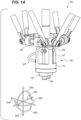
- FIG. 1A is an example according to various embodiments illustrating a side perspective view of an automated system 300 that is used to move a component 200 removably held by a gripping apparatus 100 in one or more directions.
- Components may include any small discrete parts that need to move from one area to another for further assembly or finishing operations.
- components may include shaving razor components such as shaving cartridge housings, shaving razor connectors, shaving razor cartridge dispensers.
- components can have high surface complexity but are lightweight (e.g., less than or greater than about 5 grams) depending on the surface area. However, it is understood that components are not limited to shaving razor cartridges.
- the gripping apparatus 100 includes a body 102 with a first end 108 that is attached to a component 302 of the automated system 300.
- the component 200 is removably held by a gripper head 120 secured to a second end 110 of the body 120 that is opposite to the first end 108. In some embodiments, the component 200 is removably held by the gripper head 120 using an airflow supplied to the body 102 through a hose 301.
- the component 302 of the automated system 300 is configured to move in one or more directions. In an example embodiment, the component 302 is a pick and place device that is configured to move in one or two dimensions. As shown in FIG. 1A , the component 302 is configured to move in a plurality of directions (e.g.
- the automated system 300 is a robotic system and the position of the component 302 is automatically adjusted by a controller (not shown).
- FIG. 1B is an example according to various embodiments illustrating a top view of components 200 being moved from a first location to a second location with the automated system 300 of FIG. 1A .
- the first location is a first conveyor line 310a and the second location is a second conveyor line 310b.
- the component 302 and the gripping apparatus 100 are configured to move the components 200 from the first conveyor line 310a to the second conveyor line 310b.
- the component 302 and the gripping apparatus 100 are configured to rearrange the components 200 as they are placed on the second conveyor line 310b.
- the component 302 and the gripping apparatus 100 are configured to move the components 200 from a random arrangement 320 on the first conveyor line 310 to an ordered arrangement 321 (e.g. aligned with an axis 312 along the second conveyor line 310b) on the second conveyor line 3 10b.
- the second conveyor line 310b includes one or more calibration locations 318a, 318b (whose location is known).
- the automated system 300 is calibrated by moving the component 302 to each of the one or more calibration locations 318a, 318b and recording a position of the component 302 at each calibration location 318a, 318b in a memory of the controller. These stored locations are then used by the automated system 300 to determine other locations on the second conveyor line 310b (e.g. other points along the axis 312).
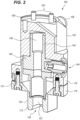
- FIG. 2 is an example according to various embodiments illustrating a sectional perspective view of the gripping apparatus 100 including the gripper head 120 that is used to releasably hold the component 200.
- the gripping apparatus 100 is similar to the apparatus 100 depicted in FIG. 1A and includes bolts 103 provided at the first end 108 of the body 102 which are used to secure the body 102 to the component 302 of the automated system 300.
- the gripping apparatus 100 includes the body 102 that defines a chamber 104 and includes an exhaust 106 at the first end 108 of the body 102.
- the gripper head 120 is attached to the second end 110 of the body 102 that is opposite to the first end 108.
- the second end 110 of the body 102 is removably attached to the gripper head 120 using one or more bolts 121 (e.g., that pass through aligned openings in the gripper head 120 and the body 102). As shown in FIG. 2 , in some embodiments the bolts 121 are used to secure a first end 170 of the gripper head 120 to the second end 110.
- FIG. 2 depicts that bolts 121 are used to removably attach the gripper head 120 to the second end 110 of the body 102, any other means appreciated by one of ordinary skill in the art can be used to secure the gripper head 120 to the second end 110 (e.g. clips, magnets and/or an air vacuum).
- any other means appreciated by one of ordinary skill in the art can be used to secure the gripper head 120 to the second end 110 (e.g. clips, magnets and/or an air vacuum).
- a second end 172 of the gripper head 120 that is opposite from the first end 170 defines an opening 122 and a nest 124 with a profile configured to locate and releasably hold the component 200 based on an air flow generated within the chamber 104 and discharged through the exhaust 106.
- a single opening 122 is depicted in the gripper head 120 of FIG. 2 , in other embodiments the gripper head 120 features multiple openings.
- the nest 124 is rigid.
- the opening 122 and the nest 124 are configured such that the component 200 is held by the gripper head 120 at a maximum velocity or maximum inertia at which the automated system 300 operates.
- the design of the gripper head 120 advantageously ensures that the component 200 is not dropped by the gripper head 120 as it is transported from the first location (e.g. the conveyor line 310a) to the second location (e.g. conveyor line 310b) by the automated system 300.
- the gripping apparatus 100 includes an air conveyor 140 positioned within the chamber 104.
- the air conveyor 140 generates the air flow through an inlet 144 and out through the exhaust 106.
- the air flow is provided to the inlet 144 via the hose 301 that is connected to a compressed air source (not shown) of the automated system 300.
- the body 102 securely surrounds and encases the air conveyor 140 within the chamber 104.
- FIG. 3A is an example according to various embodiments illustrating a cross-sectional side view of the gripping apparatus 100 including a gripper head 120a to releasably hold a component 200a.
- the nest 124 has a profile configured to locate and releasably hold the component 200a based on an air flow 142 generated within the chamber 104 and discharged through the exhaust 106.
- the air conveyor 140 defines a central bore 146 and an exhaust port 148.
- the inlet 144 includes an inlet port 145 with a nozzle 147 in communication with the central bore 146 and the exhaust port 148. As shown in FIG.
- the nozzle 147 and the inlet port 145 are oriented at a non-zero angle (e.g. orthogonal angle) to a longitudinal axis 150 of the air conveyor 140 defined by the central bore 146.
- the exhaust port 148 of the air conveyor 140 is positioned at one end of the chamber 104 that is adjacent to the first end 108 of the body 102. Based on this arrangement, the exhaust 106 at the first end 108 of the body 102 is in communication with the exhaust port 148 and the central bore 146 of the air conveyor 140. Additionally, due to this arrangement, the air flow 142 generated within the central bore 146 is discharged through the exhaust 106 at the first end 108 of the body 102.
- the exhaust 106 at the first end 108 of the body 102 defines a plurality of exhaust openings 112a through 112d.
- the plurality of exhaust openings 112a through 112d are spaced apart along an outer surface 116 of the first end 108 of the body 102 such that the generated air flow 142 is dissipated through the plurality of exhaust openings 112a through 112d.
- the exhaust openings are angularly spaced apart by about 90 degrees.
- the gripper head 120a is secured to the second end 110 of the body 102 with an O-ring 119 that forms a vacuum seal between the gripper head 120a and the second end 110 of the body 102.
- the gripper head 120a defines a recess 118 that is sized and shaped to receive the O-ring 119 in order to form the vacuum seal between the gripper head 120a and the second end 110 of the body 102 when the O-ring 119 is positioned in the recess 118 and the bolts 121 are secured through openings in both the gripper head 120a and the second end 110 of the body 102.
- an O-ring 119 is depicted in FIG.
- any means can be used to form a vacuum seal between the gripper head 120a and the second end 110 of the body 102. Additionally, as shown in FIG. 3A in one embodiment the gripper head 120a defines an inner conical surface 174 over which the recess 118 is formed.
- the component 200a may include a shaving razor cartridge cover configured to hold a shaving razor cartridge.
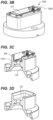
- FIGS. 3B through 3D is an example according to various embodiments illustrating perspective views of the gripper head 120a of FIG. 3A that is used to releasably hold the component 200a.
- the gripper head 120a defines a single opening 122a that is parallel to a longitudinal axis 126 of the gripper head 120a.
- the single opening 122a and the nest 124a are configured to locate and releasably hold the component 200a based on the generated air flow 142.
- a width of the single opening 122a is non-tapered over the gripper head 120a. (FIG 2B, FIGS 3A-3C ).
- the single opening 122a is circular in shape.
- the nest 124a of the gripper head 120a defines a profiled pocket 132 in communication with the single opening 122a.
- the profile pocket 132 is configured to receive a portion 204 of the component 200a releasably engaged by the gripper head 120a.
- the profile pocket 132 is elongated along a transverse axis 127 that is orthogonal to the longitudinal axis 126 of the gripper head 120a.
- the profile pocket 132 is shaped based on a shape of the portion 204 of the component 200a that is received within the profile pocket 132.
- an inner length and/or an inner width of the profile pocket 132 is based on a corresponding outer length and/or outer width of the portion 204 (e.g. the inner length and/or width of the profile pocket 132 is slightly larger so that the portion 204 fits within the profile pocket 132).
- the gripper head 120a was designed based on features of the component 200a. As previously discussed, in one embodiment the dimensions and shape of the profile pocket 132 are based on corresponding dimensions and shape of the portion 204 of the component 200a to be received in the profile pocket 132. The shaping of the profile pocket 132 may advantageously assist the gripper head 120a to locate and receive the component 200a in the profile pocket 132. Additionally, in another embodiment, the component 200a may not have openings (e.g., is solid throughout). Accordingly, the single opening 122a in the gripper head 120a may be positioned toward a center of the component 200a that is received in the profile pocket 132 to achieve a relatively equal distribution of suction force on the component 200a when the air flow 142 is generated in the body 102. Accordingly, the position of the opening 122a may be designed based on the specific geometry of the component 200a to be picked up and moved (e.g., shape and location of any voids in the component 200 that make holding the component difficult).
- FIGS. 4A through 4D A second embodiment of a gripper head 120b and associated component 200b located and removably held by the gripper head 120b will now be discussed and are depicted in FIGS. 4A through 4D .
- the component 200b may include a shaving razor cartridge housing.
- FIG. 4A is an example according to various embodiments illustrating a cross-sectional side view of the gripping apparatus 100 including a gripper head 120b to releasably hold a component 200b.
- FIG. 4A depicts that the nozzle 147 has a diameter 162 that is less than a diameter 164 of the central bore 146.
- the transition from the nozzle 147 to the central bore 146 is a venturi transition since the air flow 142 experiences a diameter transition from the nozzle 147 to the central bore 146. Also as shown in FIG.
- the central bore 146 has a diameter 166 adjacent a second end 110 of the body 102 that reduces to the diameter 164 adjacent a central portion of the central bore 146 and thus the air flow 142 passing from the bottom of the central bore 146 to central portion of the central bore 146 also experiences a venturi transition.
- the body 102 has an outer diameter 171 at the second end 110 that is greater than an outer diameter 173 of the gripper head 120 at a second end 172 where the nest 124 is formed. It was recognized that the outer diameter 173 should be sufficiently large in order to encompass the component 200 to be located and removably held by the nest 124 of the gripper head 120.
- the gripper head 120b defines one or more openings that are different from the single opening 122a in the gripper head 120a. Additionally, in this embodiment the gripper head 120b defines a nest 124b which is different from the nest 124a of the gripper head 120a. In these embodiments the gripper head 120b has a different set of openings and nest since the gripper head 120b is configured to locate and releasably hold a component 200b with different characteristics from the component 200a located and releasably held by the gripper head 120a. In these embodiments, the gripper head 120b defines angled openings 134 that are angled relative to a longitudinal axis 126 of the gripper head 120b.
- the angled openings 134 form an angle 138 with the longitudinal axis 126.
- the angle 138 is in a range from 30 degrees to 60 degrees.
- no specific value of the angle 138 is necessary since the angle 138 is for merging the paths of the air flow through the single opening 136 and the angled openings 134 based on a location of suction to be applied to the component 200b.
- the value of the angle 138 is determined based on a clearance that is required for the automated system 300 employing the gripper head 120b to locate the component 200b within the recess 139 of the gripper head 120b. As further shown in FIG.
- the gripper head 120b further defines a single opening 136 that is oriented parallel to the longitudinal axis 126.
- the angled openings 134 have a first width 135 and the single opening 136 has a second width 137 that is different from the first width 135.
- the first width 135 is less than the second width 137.
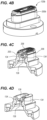
- FIGS. 4B through 4D is an example according to various embodiments illustrating perspective views of the gripper head 120b of FIG. 4A to releasably hold the component 200b.
- the nest 124b of the gripper head 120a defines a recess 139.
- FIG. 4C depicts that in some embodiments the component 200b includes a solid portion 206 (e.g. not porous with no openings), a portion with openings 208 and a male portion 205.
- the recess 139 is shaped and sized to receive the male portion 205 of the component 200b.
- the angled openings 134 are aligned with the solid portion 206 of the component 200b and the single opening 136 is aligned with the openings 208 of the component 200b.
- the openings may be designed and sized to maximize force on a land (e.g., flat open space to apply suction force) on the component 200b.
- the particular arrangement of the openings 134, 136 with the respective solid portion 206 and openings 208 of the component 200b may achieve certain advantages. For example, this particular arrangement may distribute a suction force across the component 200b (e.g. across the solid portion 206 and openings 208) based on the generated air flow 142.
- the wider opening 136 is aligned with the openings 208 and the narrower openings 134 are aligned with the solid portion 206 since a larger air flow is necessary across the openings 208 relative to the solid portion 206 in order to achieve an equalized suction force across the component 200b.
- FIGS. 5A through 5C A third embodiment of a gripper head 120c and associated component 200c located and removably held by the gripper head 120c will now be discussed and are depicted in FIGS. 5A through 5C .
- the component 200c is another possible example of a shaving razor cartridge cover.
- FIG. 5A is an example according to various embodiments illustrating a cross-sectional side view of the gripping apparatus 100 including the gripper head 120c to releasably hold the component 200c.
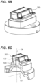
- FIGS. 5B through 5C is an example according to various embodiments illustrating perspective views of the gripper head 120c of FIG. 5A to releasably hold the component 200c.
- the gripper head 120c includes a single opening 122c. In one embodiment, unlike the single opening 122a of FIG. 3A (non-tapered width), the width of the single opening 122c is tapered over the gripper head 120c.
- the gripper head 120c and the single opening 122c are elongated along a transverse axis 127 of the gripper head 120c that is orthogonal to the longitudinal axis 126.
- the elongated single opening 122c is dimensioned to distribute a suction force across the component 200c along the transverse axis 127 based on the generated air flow 142.
- the nest 124c of the gripper head 120c is a profiled surface 130 that is elongated along the traverse axis 127.
- the profiled surface 130 is dimensioned along the transverse axis 127 based on a corresponding inner diameter of a recess 202 of the component 200c along the transverse axis 127. Additionally, as shown in FIG. 5C , the profiled surface 130 is configured to be received within the recess 202 defined by the component 200c. In an example embodiment, an outer diameter of the profiled surface 130 along the transverse axis 127 is less than an inner diameter of the recess 202 along the transverse axis 127 but is sufficiently close to the inner diameter of the recess 202 in order to achieve a close fit of the profiled surface 130 within the recess 202.
- the gripper head 120c was designed with these particular features (e.g. elongated opening 122c along the transverse axis 127 and/or elongated profiled surface 130 along the transverse axis 127) to achieve one or more advantages with respect to locating and removably holding the component 200c.
- the single opening 122c and the profiled surface 130 may be shaped and dimensioned along the transverse axis 127 to advantageously enhance the fit of the profile surface 130 within the recess 202 and further distributes the suction force on the component 200c across the transverse axis 127.
- the present invention is not limited to these embodiments and in some embodiments includes a kit is provided that can be used with the gripping apparatus 100 in order to secure different gripper heads 120 to the body 102 in order to move different types of components 200 from the first location to the second location.
- a kit is provided that can be used with the gripping apparatus 100 in order to secure different gripper heads 120 to the body 102 in order to move different types of components 200 from the first location to the second location. This advantageously permits the same gripping apparatus 100 and body 102 that can otherwise only transport one type of component to be converted into an improved gripping apparatus that can be used to transport multiple different types of components by securing different gripper heads to the body 102 of the gripping apparatus 100.
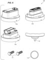
- FIG. 6 is an example according to various embodiments illustrating a kit 350 for the gripping apparatus 100 including multiple gripper heads 120a, 120b, 120c used to transport multiple components 200a, 200b, 200c from a first location to a second location. Although three gripper heads 120a, 120b, 120c are depicted in FIG. 6 , the kit 350 is not limited to including one or more of these gripper heads 120a, 120b, 120c and includes other gripper heads with a different design that can be similarly employed to locate and releasably hold different components other than the components 200a, 200b, 200c.
- the kit 350 includes a calibration tip 125.
- the calibration tip 125 can be secured to the second end 110 of the body 102 in a similar manner as the gripper heads 120 (e.g. passing bolts 121 through aligned openings in the calibration tip 125 and the second end 110 of the body 102). This calibration tip 125 can then be used to calibrate a position of the system in which the gripping apparatus 100 is employed.
- FIG. 1C depicts a pair of calibration locations 318a, 318b on the second conveyor line 310b.
- the calibration tip 125 is secured to the second end 110 of the body 102 after which the body 102 is moved by the component 302 of the automated system 300 until the calibration tip 125 is at each calibration location 318a, 318b.
- a controller (not shown) of the automated system 300 then stores the position of the calibration tip 125 in a memory which is then used in positioning the body 102 with the attached gripper head 120 at one or more other locations on the second conveyor line 310b.
- the kit 350 includes one or more components to facilitate removing a first gripper head 120a from the second end 110 of the body 102 and securing a second gripper head 120b (different from the first gripper head 120a) to the second end 110 of the body 102.
- This advantageously facilities the same gripping apparatus 100 being used to transport one or more components 200a (with the gripper head 120a) from the first location to the second location and after which being used to transport one or more components 200b (with the gripper head 120b) from the first location to the second location.
- the kit is not limited to these gripper heads and components and thus can facilitate the removal and replacement of any two different gripper heads in order to facilitate the transport of any two different components which can be located and releasably held by the two different gripper heads.
- the components used to facilitate the removal and replacement of gripper heads 120 from the second end 110 of the body 102 include the O-ring 119 and the bolts 121.
- the first gripper head 120a is removed by removing the bolts 121 from the second end 110 of the body 102 and removing the O-ring 119 from the recess 118 in the first gripper head 120a.
- the O-ring 119 is then positioned in the recess 118 of the second gripper head 120b.
- the bolt openings of the second gripper head 120b are then aligned with the bolt openings in the second end 110 of the body 102 and the bolts 121 are passed through the aligned openings to secure the second gripper head 120b to the second end 110 of the body 102.
- These steps can be repeated in order to replace any gripper head with another gripper head, and thus facilitates the versatility of the gripping apparatus 100 being used to transport multiple different types of components 200.
- the O-ring 119 and bolts 121 are depicted in FIG. 6
- the kit 350 is not limited to these particular components for removing and replacing the gripper head and in other embodiments includes other components or means (e.g. clips, magnetic or an air vacuum) for removing and replacing the gripper heads.
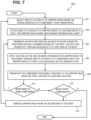
- FIG. 7 is an example according to various embodiments illustrating a flowchart of a method 400 for transporting one or more components 200 using the one or more gripper heads 120 of the kit 350 of FIG. 6 .
- the method 400 is used to transport one or more components from the first conveyor line 310a to the second conveyor line 310b ( FIG. 1B ).
- the method 400 begins at step 401 where the gripper head 120 is selected to transport the one or more components 200.
- one or more characteristics of the components 200 are determined and are used to select the gripper head 120.
- the gripper head 120a is selected in order to transport one or more components 200a.
- the gripper head 120b is selected in order to transport one or more components 200b.
- the gripper head 120c is selected in order to transport one or more components 200c.
- step 401 is not limited to selecting among the gripper heads 120a, 120b, 120c to transport the components 200a, 200b, 200c, and includes other gripper heads 120 that are designed in a similar manner as the gripper heads 120a, 120b, 120c to transport components 200 other than the components 200a, 200b, 200c.
- step 402 the gripper head 120 selected in step 401 is secured to the second end 110 of the body 102 of the gripper apparatus 100.
- the O-ring 119 is positioned in the recess 118 of the gripper head 120.
- the bolt openings in the gripper head 120 are then aligned with corresponding bolt openings in the second end 110 of the body 102.
- the bolts 121 are then passed through the aligned bolt openings to secure the gripper head 120 to the second end 110 of the body 102.
- step 402 secures the gripper head 120 to the second end 110 of the body 102 to form a vacuum seal between the gripper head 120 and the second end 110 such that air does not pass between the gripper head 120 and the second end 110 of the body 102.
- other means are employed in step 402 to secure the gripper head 120 to the second end 110 of the body 102 (e.g. clips, magnets or a vacuum source).
- the gripper head 120a with the single opening 122a and the nest 124a is attached to the second end 110 of the body 102.
- step 404 the air flow 142 is generated through the inlet 144 of the air conveyor 140 and out through the exhaust 106 at the first end 108 of the body 102.
- a compressed air source (not shown) supplies the air flow 142 through the hose 301 ( FIG. 1A ) to the inlet 144.
- a pressure of the compressed air is selected (e.g. between 4 bar, 5 bar and 6 bar) that is supplied to the inlet 144 from the compressed air source. In these embodiments, the value of the pressure is selected based on one or more characteristics of the component 200.
- step 406 suction force is applied to the component 200 through the gripper head 120 so that the nest 124 of the gripper head 120 locates and releasably holds the component 200.
- step 406 is performed to the component(s) 200 located at the first location (e.g. first conveyor line 310a). This suction force is applied through the gripper head 120 due to the generated air flow 142 at step 404.
- the gripper head 120a is attached to the second end 110 of the body 102 in step 402
- suction is applied to the component 200a via the single opening 122a to releasably hold the component 200a with the gripper head 120a at the first location.
- the applying step 406 includes the male portion 204 of the component 200a being received within the profiled pocket 132 of the gripper head 120a to releasably hold the component 200a with the gripper head 120a.
- step 406 suction is applied to the component 200b via the angled openings 134 and the single opening 136 to releasably hold the second component 200b based on the generating step 404.
- the angled openings 134 are aligned with the solid portion 206 of the component 200b and the single opening 136 is oriented at the openings 208 of the component 200b such that the applying step 406 distributes a suction force across the solid portion 206 and openings 208 of the component 200b based on the generating step 404.
- the elongated single opening 122c is dimensioned such that the applying step 406 distributes a suction force across the component 200c along the transverse axis 127 based on the generating 404 step. Additionally, in this example embodiment, the applying step 406 causes the profiled surface 130 of the component 120c to be received within the recess 202 defined by the component 200c.
- step 408 the component 200 releasably held by the gripper head 120 at the first location in step 406 is transported to a second location.
- the component 302 of the automated system 300 is moved in one or more directions (e.g. along one or more axes 304a, 304b, 304c and/or in one or more rotational directions 305a, 305b, 305c) until the component 200 is at the second location (e.g. second conveyor line 310b).
- the component 302 is moved until the component 200 is at a particular location at the second location (e.g. along axis 312 of the second conveyor line 31 0b) so that the components 200 are arranged with a particular arrangement at the second location (e.g. ordered arrangement 321 along the axis 312).
- the method 400 then moves to block 310 where it is determined whether more components 200 of the same type moved in step 308 are to be moved. If the result of this determination is in the affirmative, the method 400 proceeds back to step 404 and steps 404 through 408 are repeated for another component 200 of the same type moved in step 408. This is repeated until all of the components 200 of the same type are moved from the first location to the second location. If the determination is in the negative, the method 400 proceeds to block 412.
- the method 400 determines whether additional components 200 other than the component 200 moved in the previous iteration of step 408 are to be moved. If the result of this determination is in the affirmative, the method 400 moves to step 413. If the result of this this determination is in the negative, the method 400 ends since no more components 200 are to be moved from the first location to the second location.
- step 413 the method 400 removes the gripper head 120 that is secured to the second end 110 of the body 102.
- step 413 is performed after all components 200 to be moved by the gripper head 120 have been moved from the first location to the second location and more components 200 of a different type still need to be transported from the first location to the second location.
- step 413 will be discussed with respect to removing the gripper head 120a which is performed after transporting the components 200a from the first location to the second location.
- step 413 is performed after all of the components 200a are moved with the gripper head 120a.
- step 413 the bolts 121 are removed from the second end 110 of the body 102 and the gripper head 120a is removed from the second end 110.
- the O-ring 119 is also removed from the recess 118 of the gripper head 120a.
- step 413 the method 400 proceeds back to steps 401 and 402 where the gripper head 120 is replaced with a different gripper head 120 in order to move components 200 that are different from the components 200 moved by the gripper head 120 removed in step 413.
- the gripper head 120b is selected in step 401 due to components 200b which need to be transported from the first location to the second location.
- the O-ring 119 is inserted in the recess 118 of the gripper head 120b. The gripper head 120b is then secured to the second end 110 of the body 102 using the bolts 121.
- steps 401 and 402 are discussed in the context of the example of replacing the gripper head 120a with the gripper head 120b, these steps can be similarly performed when replacing any gripper head with a different gripper head.
- steps 404 through 408 are performed to transport the components 200b from the first location to the second location.
- FIG. 8 is an example according to various embodiments illustrating a system 500 for 3D printing one or more gripper heads 120 of the kit 350 of FIG. 6 .
- the system 500 includes a 3D printer 502 that is used to 3D print one or more of the components 200.
- the system 500 also includes a controller 504 with a memory 505 that is communicatively coupled to the 3D printer 502.
- the system 500 also includes a scanner 506 is used to scan one or more of the components 200.
- the scanner 506 is communicatively coupled to the controller 504 and is configured to transmit scan data (e.g.
- CAD data of the component 200 to the controller 504.
- the scan data indicates the geometry of the component 200 which is used by the controller 504 to obtain data (e.g. CAD data) indicating a geometry of a gripper head 120 that can be used to locate and releasably hold the component 200.
- a correspondence between the geometry data of the component 200 and the geometry data of the gripper head 120 is stored in the memory 505 of the controller 504.
- the controller 504 determines the geometry data of the gripper head 120 to be 3D printed from the memory 505 based on the geometry data of the component 200 that is received from the scanner 506 (or from another remote data source).
- the controller 504 transmits this data indicating the geometry of the gripper head 120 to the 3D printer 502 which then 3D prints the gripper head 120 to be used in transporting the component 200.
- the data indicating the geometry of the component 200 and/or the gripper head 120 is downloaded to the memory 505 of the controller 504 from a remote source.
- the scanner 506 is not used since the data indicating the geometry of the gripper head 120 is downloaded from a remote source other than the scanner 506.
- FIG. 9 is an example according to various embodiments illustrating a flowchart of a method 550 for forming the one or more gripper heads 120 using the system 500 of FIG. 8 .
- the method 550 includes obtaining 552 3D data (e.g. CAD data) based on a geometry of a component 200.
- step 552 is performed using the scanner 506 which scans a component 200 to be transported by the gripping apparatus 100.
- the scanner 506 scans the component 200 to obtain data (e.g. CAD data) indicating a geometry of the component 200.
- This data is then transmitted from the scanner 506 to the controller 504 which determines corresponding data indicating a geometry of a gripper head 120 to be used to transport the component 200.
- the memory 505 of the controller 504 stores a correspondence between the geometry data of the component 200 and the geometry data of the gripper head 120 to be used to transport the component 200.
- the controller 504 uses the memory 505 to determine the geometry data of the gripper head 120 based on the received geometry data of the component 200.
- the 3D data obtained in step 502 indicates solid regions and openings of the component 200. In one embodiment, for the component 200b the 3D data obtained in step 502 indicates the solid regions 206 and the openings 208 in the component 200b.
- the controller 504 uses this obtained 3D data to determine the data indicating the geometry of the gripper head 120b (e.g. with the angled openings 134 and single opening 136) to locate and releasably hold the component 200b. In one example embodiment, the controller 504 determines the data indicating the geometry of the gripper head 120b by positioning the angled openings 134 to be aligned with the openings 208 and the single opening 136 to be aligned with the solid portions 206 of the component 200b. As previously discussed, this geometry of the gripper head 120b achieves notable advantages, such as distributing the suction force across the component 200b.
- the method 550 includes a step of forming the gripper head 120 based on the 3D data obtained in step 552.
- the 3D printer 502 forms the gripper head 120 based on the geometry data of the gripper head 120 received from the controller 504.
- the 3D printer 502 forms the nest 124 and the one or more openings 122 in the gripper head 120. It was recognized that the 3D printing advantageously permits the gripper head 120 to be formed with intricate curvatures and openings (e.g. angled opening 134 in FIG. 4D ) that would not be possible with conventional manufacturing methods (e.g. injection molding, machining, etc.).
- step 554 the 3D printer 502 forms the nest 124 and the one or more openings 122 in the gripper head 120 to locate and releasably hold the component 200 based on suction being applied through the one or more openings 122.
- the 3D printing in step 554 is performed using 3D printable material (e.g. one of carbon fiber, metal, polymer and impregnated polymer material). Additionally, in another example embodiment, the 3D printing in step 554 is performed such that the 3D printed gripper head 120 has a weight in a range between 0.1 kg and 0.5 kg.
- 3D printable material e.g. one of carbon fiber, metal, polymer and impregnated polymer material. Additionally, in another example embodiment, the 3D printing in step 554 is performed such that the 3D printed gripper head 120 has a weight in a range between 0.1 kg and 0.5 kg.
- the obtaining step 502 includes obtaining 3D data indicating the geometry of the component 200a.
- the obtaining step 502 includes identifying the male portion 204 of the component 200a.
- the forming step 504 includes forming the nest 124 of the gripper head 120a with the profiled pocket 132 in communication with the opening 122a such that the male portion 204 of the component 200a is received within the profiled pocket 132 based on suction applied through the opening 122a.
- the forming step 504 also includes forming the single opening 122a in the gripper head 120a that is parallel to the longitudinal axis 126 of the gripper head 120a so that the gripper head 120a is configured to releasably hold the component 200a based on suction applied through the opening 122a.
- the forming step 504 includes forming the opening 122a with a fixed width over the gripper head 120a.
- the obtaining step 502 includes obtaining 3D data indicating the geometry of the component 200b. In one example embodiment, the obtaining step 502 includes obtaining 3D data that indicates the solid portion 206 and openings 208 of the component 200b. In this example embodiment, the forming step 504 includes orienting the multiple angled openings 134 such that they are aligned with the solid portion 206 of the component 200b and orienting the single opening 136 such that it is aligned with the openings 208 of the component 200b to distribute a suction force across the solid portion and openings 206, 208 of the component 200b upon applying suction via the multiple angled openings 134 and the single opening 136.
- step 504 includes sizing the multiple angled openings 134 with the first width 135 and sizing the single opening 136 with the second width 137 that is different (e.g. greater than) from the first width 135.
- the forming step 504 includes forming the single opening 136 in the gripper head 120b that is parallel to the longitudinal axis 126 such that the component 200b is releasably held by the gripper head 120b upon applying suction via the single opening 136 and the multiple angled openings 134.
- the forming step 504 involves forming the recess 139 in the gripper head 120b to receive the male portion 205 of the component 200b.
- the obtaining step 502 includes obtaining 3D data indicating the geometry of the component 200c. In some embodiments, the obtaining step 502 includes obtaining 3D data that indicates the recess 202 defined by the component 200c.
- the forming step 504 includes forming the profiled surface 130 in the gripper head 120c that is elongated along the transverse axis 127 and is in communication with the opening 122c so that the profiled surface 130 is received within the recess 202 of the component 200c based on suction applied through the opening 122c. In another embodiment, the forming step 504 then includes forming the opening 122c including tapering a width of the opening 122c over the gripper head 120c.
- the forming step 504 includes elongating the opening 122c along the transverse axis 127 of the gripper head 120c that is orthogonal to the longitudinal axis 126. In these embodiments, the forming step 504 further includes dimensioning the elongated opening 122c such that the suction applied through the elongated opening 122c is distributed across the component 200c along the transverse axis 127.
- step 556 a determination is made of whether more components are to be transported other than the component for which the gripper head 120 was formed in step 554. In an embodiment, in step 556 a determination is made whether a different type of component 200 needs to be transported other than the component 200 for which the gripper head 120 was formed in the previous iteration of steps 552 and 554. If this determination is in the affirmative, then the method 550 proceeds back to step 552. If the determination is in the negative, the method 550 ends.
Landscapes
- Engineering & Computer Science (AREA)
- Robotics (AREA)
- Mechanical Engineering (AREA)
- Manipulator (AREA)
Abstract
Description
- The present disclosure relates generally to grippers used in conjunction with vacuum generators to suction components in order to transport them from one location to another.
- Standard suction cups or mechanical grippers are available which are used in conjunction with vacuum generators to suction one or more components and transport them from one location to another. However, these standard suction cups require the component have a minimum surface area in order to generate the necessary suction to hold the component. Additionally, these standard suction cups only work with components capable of withstanding a threshold suction force established by the suction cup. Hence, these conventional suction cups are not suitable for transporting components that have minimal surface area and/or which are delicate and not capable of withstanding these threshold suction forces.
- Additionally, in addition to a primary valve that is used to establish the vacuum suction, these standard suction cups typically feature a secondary valve to provide an ejection pulse to release the component from the suction cup after transport. Hence, by introducing these secondary valves, these conventional suction cups increase a cycle time of the unit in transporting components between locations.
- These conventional suction cups also require a large suction rate that necessitates an increased weight and size of the end of an arm tooling on which the suction cup is positioned. This increased size and weight necessarily reduces the performance of the system.
- Various embodiments solve the above-mentioned problems and provide a gripper head apparatus for transporting components from one location to another, especially those components having a minimal surface area or are delicate such that they are not capable of withstanding threshold suction forces established by conventional suction cups. Various embodiments also provide a kit including a plurality of gripper heads to be used with the gripper head apparatus. Various embodiments also provide a method for transporting components from one location to another using the gripper head apparatus. Various embodiments also provide a method for forming multiple gripper heads for use in the method for transporting the components.
- In a first set of embodiments, a gripping apparatus is provided for transporting components from one location to another. The gripping apparatus includes a body defining a chamber and an exhaust at a first end of the body. The apparatus also includes a gripper head configured to be attached to a second end of the body opposite to the first end. The gripper head defines one or more openings and a nest having a profile configured to locate and releasably hold a component based on an air flow generated within the chamber and discharged through the exhaust. The apparatus also includes an air conveyor positioned within the chamber. The air conveyor is configured to generate the air flow through an inlet and out through the exhaust. The air conveyor defines a central bore and an exhaust port. The inlet includes an inlet port with a nozzle in communication with the central bore and the exhaust port.
- In a second set of embodiments, a kit is provided for a gripping apparatus. The gripping apparatus includes a body defining a chamber and an exhaust at a first end of the body. The gripping apparatus also includes an air conveyor positioned within the chamber. The air conveyor is configured to generate an air flow through an inlet and out through the exhaust. The kit includes a plurality of gripper heads each configured to be attached to a second end of the body opposite to the first end. Each gripper head defines a respective interchangeable nest that is different among the plurality of gripper heads. Each gripper head is configured to locate and releasably hold one of a plurality of components based on the air flow generated within the chamber and discharged through the exhaust.
- In a third set of embodiments, a method is provided for transporting components from a first location to a second location using a gripping apparatus. The gripping apparatus includes a body defining a chamber and includes an exhaust at a first end of the body. The gripping apparatus also includes an air conveyor positioned within the chamber. The method includes attaching one of a plurality of gripper heads to a second end of the body opposite to the first end. The gripper head defines one or more openings and a nest. The method further includes generating an air flow through an inlet of the air conveyor and out through the exhaust. The method further includes applying suction via the one or more openings in the gripper head to locate and releasably hold one of the plurality of components with the gripper head at the first location based on the generating step. The method further includes transporting the component releasably held to the gripper head from the first location to a second location.
- In a fourth set of embodiments, a method is provided for forming one or more gripper heads to be used with a gripping apparatus. The method includes obtaining 3D data based on a geometry of a component. The method also includes forming one gripper head comprising 3D printing the gripper head based on the obtained 3D data. The forming step includes forming one or more openings in the gripper head and forming a nest of the gripper head to locate and releasably hold the component based on suction being applied through the one or more openings.
- Many aspects of this disclosure can be better understood with reference to the following figures.
-
FIG. 1A is an example according to various embodiments illustrating a side perspective view of an automated system that is used to move a gripper head apparatus in one or more directions. -
FIG. 1B is an example according to various embodiments illustrating a top view of components being moved from a first location to a second location with the automated system ofFIG. 1A . -
FIG. 2 is an example according to various embodiments illustrating a sectional perspective view of a gripping apparatus including a gripper head to releasably hold a component. -
FIG. 3A is an example according to various embodiments illustrating a cross-sectional side view of a gripping apparatus including a gripper head to releasably hold a component. -
FIGS. 3B through 3D is an example according to various embodiments illustrating perspective views of the gripper head ofFIG. 3A to releasably hold the component. -
FIG. 4A is an example according to various embodiments illustrating a cross-sectional side view of a gripping apparatus including a gripper head to releasably hold a component. -
FIGS. 4B through 4D is an example according to various embodiments illustrating perspective views of the gripper head ofFIG. 4A to releasably hold the component. -
FIG. 5A is an example according to various embodiments illustrating a cross-sectional side view of a gripping apparatus including a gripper head to releasably hold a component. -
FIGS. 5B through 5C is an example according to various embodiments illustrating perspective views of the gripper head ofFIG. 5A to releasably hold the component. -
FIG. 6 is an example according to various embodiments illustrating a kit for a gripping apparatus including multiple gripper heads used to transport multiple components from a first location to a second location. -
FIG. 7 is an example according to various embodiments illustrating a flowchart of a method for transporting one or more components using one or more gripper heads of the kit ofFIG. 6 . -
FIG. 8 is an example according to various embodiments illustrating a system for 3D printing one or more gripper heads of the kit ofFIG. 6 . -
FIG. 9 is an example according to various embodiments illustrating a flowchart of a method for forming the one or more gripper heads using the system ofFIG. 8 . - It should be understood that the various embodiments are not limited to the examples illustrated in the figures.
- This disclosure is written to describe the invention to a person having ordinary skill in the art, who will understand that this disclosure is not limited to the specific examples or embodiments described. The examples and embodiments are single instances of the invention which will make a much larger scope apparent to the person having ordinary skill in the art. Unless defined otherwise, all technical and scientific terms used herein have the same meaning as commonly understood by the person having ordinary skill in the art. It is also to be understood that the terminology used herein is for the purpose of describing examples and embodiments only, and is not intended to be limiting, since the scope of the present disclosure will be limited only by the appended claims.
- All the features disclosed in this specification (including any accompanying claims, abstract, and drawings) may be replaced by alternative features serving the same, equivalent, or similar purpose, unless expressly stated otherwise. Thus, unless expressly stated otherwise, each feature disclosed is one example only of a generic series of equivalent or similar features. The examples and embodiments described herein are for illustrative purposes only and that various modifications or changes in light thereof will be suggested to the person having ordinary skill in the art and are to be included within the spirit and purview of this application. Many variations and modifications may be made to the embodiments of the disclosure without departing substantially from the spirit and principles of the disclosure. All such modifications and variations are intended to be included herein within the scope of this disclosure. For example, unless otherwise indicated, the present disclosure is not limited to particular materials, reagents, reaction materials, manufacturing processes, or the like, as such can vary. It is also to be understood that the terminology used herein is for purposes of describing particular embodiments only and is not intended to be limiting. It is also possible in the present disclosure that steps can be executed in different sequence where this is logically possible.
- All numeric values are herein assumed to be modified by the term "about," whether or not explicitly indicated. The term "about" generally refers to a range of numbers that one of skill in the art would consider equivalent to the recited value (for example, having the same function or result). In many instances, the term "about" may include numbers that are rounded to the nearest significant figure.
- In everyday usage, indefinite articles (like "a" or "an") precede countable nouns and noncountable nouns almost never take indefinite articles. It must be noted, therefore, that, as used in this specification and in the claims that follow, the singular forms "a," "an," and "the" include plural referents unless the context clearly dictates otherwise. Thus, for example, reference to "a support" includes a plurality of supports. Particularly when a single countable noun is listed as an element in a claim, this specification will generally use a phrase such as "a single." For example, "a single support."
- Where a range of values is provided, it is understood that each intervening value, to the tenth of the unit of the lower limit (unless the context clearly dictates otherwise), between the upper and lower limit of that range, and any other stated or intervening value in that stated range, is encompassed within the disclosure. The upper and lower limits of these smaller ranges may independently be included in the smaller ranges and are also encompassed within the disclosure, subject to any specifically excluded limit in the stated range. Where the stated range includes one or both of the limits, ranges excluding either or both of those included limits are also included in the disclosure.
- In this specification and in the claims that follow, reference will be made to a number of terms that shall be defined to have the following meanings unless a contrary intention is apparent.
-
FIG. 1A is an example according to various embodiments illustrating a side perspective view of anautomated system 300 that is used to move acomponent 200 removably held by agripping apparatus 100 in one or more directions. Components may include any small discrete parts that need to move from one area to another for further assembly or finishing operations. For example, components may include shaving razor components such as shaving cartridge housings, shaving razor connectors, shaving razor cartridge dispensers. In yet another example, components can have high surface complexity but are lightweight (e.g., less than or greater than about 5 grams) depending on the surface area. However, it is understood that components are not limited to shaving razor cartridges. In an embodiment, thegripping apparatus 100 includes abody 102 with afirst end 108 that is attached to acomponent 302 of theautomated system 300. In one embodiment, thecomponent 200 is removably held by agripper head 120 secured to asecond end 110 of thebody 120 that is opposite to thefirst end 108. In some embodiments, thecomponent 200 is removably held by thegripper head 120 using an airflow supplied to thebody 102 through ahose 301. In one embodiment, thecomponent 302 of theautomated system 300 is configured to move in one or more directions. In an example embodiment, thecomponent 302 is a pick and place device that is configured to move in one or two dimensions. As shown inFIG. 1A , thecomponent 302 is configured to move in a plurality of directions (e.g. up to six directions) including along one ormore axes rotational directions respective axes automated system 300 is a robotic system and the position of thecomponent 302 is automatically adjusted by a controller (not shown). -
FIG. 1B is an example according to various embodiments illustrating a top view ofcomponents 200 being moved from a first location to a second location with theautomated system 300 ofFIG. 1A . In one embodiment, the first location is afirst conveyor line 310a and the second location is asecond conveyor line 310b. In these embodiments, thecomponent 302 and thegripping apparatus 100 are configured to move thecomponents 200 from thefirst conveyor line 310a to thesecond conveyor line 310b. As shown inFIG. 1B , in some embodiments in addition to moving thecomponents 200 from thefirst conveyor line 310a to thesecond conveyor line 310b thecomponent 302 and thegripping apparatus 100 are configured to rearrange thecomponents 200 as they are placed on thesecond conveyor line 310b. In an example embodiment, thecomponent 302 and thegripping apparatus 100 are configured to move thecomponents 200 from arandom arrangement 320 on the first conveyor line 310 to an ordered arrangement 321 (e.g. aligned with anaxis 312 along thesecond conveyor line 310b) on the second conveyor line 3 10b. Additionally, as shown inFIG. 1B thesecond conveyor line 310b includes one ormore calibration locations automated system 300 is calibrated by moving thecomponent 302 to each of the one ormore calibration locations component 302 at eachcalibration location automated system 300 to determine other locations on thesecond conveyor line 310b (e.g. other points along the axis 312). - The
gripping apparatus 100 that was discussed with reference toFIG. 1A will now be described in more detail.FIG. 2 is an example according to various embodiments illustrating a sectional perspective view of thegripping apparatus 100 including thegripper head 120 that is used to releasably hold thecomponent 200. In some embodiments, thegripping apparatus 100 is similar to theapparatus 100 depicted inFIG. 1A and includesbolts 103 provided at thefirst end 108 of thebody 102 which are used to secure thebody 102 to thecomponent 302 of theautomated system 300. - In an embodiment, the
gripping apparatus 100 includes thebody 102 that defines achamber 104 and includes anexhaust 106 at thefirst end 108 of thebody 102. Thegripper head 120 is attached to thesecond end 110 of thebody 102 that is opposite to thefirst end 108. In some embodiments, thesecond end 110 of thebody 102 is removably attached to thegripper head 120 using one or more bolts 121 (e.g., that pass through aligned openings in thegripper head 120 and the body 102). As shown inFIG. 2 , in some embodiments thebolts 121 are used to secure afirst end 170 of thegripper head 120 to thesecond end 110. AlthoughFIG. 2 depicts thatbolts 121 are used to removably attach thegripper head 120 to thesecond end 110 of thebody 102, any other means appreciated by one of ordinary skill in the art can be used to secure thegripper head 120 to the second end 110 (e.g. clips, magnets and/or an air vacuum). - As shown in
FIG. 2 , asecond end 172 of thegripper head 120 that is opposite from thefirst end 170 defines anopening 122 and anest 124 with a profile configured to locate and releasably hold thecomponent 200 based on an air flow generated within thechamber 104 and discharged through theexhaust 106. Although asingle opening 122 is depicted in thegripper head 120 ofFIG. 2 , in other embodiments thegripper head 120 features multiple openings. In one example embodiment, thenest 124 is rigid. In another example embodiment, theopening 122 and thenest 124 are configured such that thecomponent 200 is held by thegripper head 120 at a maximum velocity or maximum inertia at which theautomated system 300 operates. In this example embodiment, the design of thegripper head 120 advantageously ensures that thecomponent 200 is not dropped by thegripper head 120 as it is transported from the first location (e.g. theconveyor line 310a) to the second location (e.g.conveyor line 310b) by theautomated system 300. - Additionally, in an embodiment, the
gripping apparatus 100 includes anair conveyor 140 positioned within thechamber 104. Theair conveyor 140 generates the air flow through aninlet 144 and out through theexhaust 106. As previously discussed, in some embodiments the air flow is provided to theinlet 144 via thehose 301 that is connected to a compressed air source (not shown) of theautomated system 300. As shown inFIG. 2 , in one embodiment, thebody 102 securely surrounds and encases theair conveyor 140 within thechamber 104. -
FIG. 3A is an example according to various embodiments illustrating a cross-sectional side view of thegripping apparatus 100 including agripper head 120a to releasably hold acomponent 200a. As shown inFIG. 3A , thenest 124 has a profile configured to locate and releasably hold thecomponent 200a based on anair flow 142 generated within thechamber 104 and discharged through theexhaust 106. Theair conveyor 140 defines acentral bore 146 and anexhaust port 148. Theinlet 144 includes aninlet port 145 with anozzle 147 in communication with thecentral bore 146 and theexhaust port 148. As shown inFIG. 3A , in one embodiment thenozzle 147 and theinlet port 145 are oriented at a non-zero angle (e.g. orthogonal angle) to a longitudinal axis 150 of theair conveyor 140 defined by thecentral bore 146. As further shown inFIG. 3A , in an embodiment theexhaust port 148 of theair conveyor 140 is positioned at one end of thechamber 104 that is adjacent to thefirst end 108 of thebody 102. Based on this arrangement, theexhaust 106 at thefirst end 108 of thebody 102 is in communication with theexhaust port 148 and thecentral bore 146 of theair conveyor 140. Additionally, due to this arrangement, theair flow 142 generated within thecentral bore 146 is discharged through theexhaust 106 at thefirst end 108 of thebody 102.FIG. 3A further depicts that in one embodiment theexhaust 106 at thefirst end 108 of thebody 102 defines a plurality ofexhaust openings 112a through 112d. As further shown inFIG. 3A the plurality ofexhaust openings 112a through 112d are spaced apart along anouter surface 116 of thefirst end 108 of thebody 102 such that the generatedair flow 142 is dissipated through the plurality ofexhaust openings 112a through 112d. In an example embodiment, where fourexhaust openings 112a through 112d are provided, the exhaust openings are angularly spaced apart by about 90 degrees. - As shown in
FIG. 3A , in an embodiment thegripper head 120a is secured to thesecond end 110 of thebody 102 with an O-ring 119 that forms a vacuum seal between thegripper head 120a and thesecond end 110 of thebody 102. In one embodiment, thegripper head 120a defines arecess 118 that is sized and shaped to receive the O-ring 119 in order to form the vacuum seal between thegripper head 120a and thesecond end 110 of thebody 102 when the O-ring 119 is positioned in therecess 118 and thebolts 121 are secured through openings in both thegripper head 120a and thesecond end 110 of thebody 102. Although an O-ring 119 is depicted inFIG. 3A , in other embodiments any means can be used to form a vacuum seal between thegripper head 120a and thesecond end 110 of thebody 102. Additionally, as shown inFIG. 3A in one embodiment thegripper head 120a defines an innerconical surface 174 over which therecess 118 is formed. - A first embodiment of the
gripper head 120a and associatedcomponent 200a located and releasably held by thegripper head 120a will now be discussed and is depicted inFIGS. 3B through 3D . In an embodiment, thecomponent 200a may include a shaving razor cartridge cover configured to hold a shaving razor cartridge. -
FIGS. 3B through 3D is an example according to various embodiments illustrating perspective views of thegripper head 120a ofFIG. 3A that is used to releasably hold thecomponent 200a. As shown inFIG. 3A , in one embodiment thegripper head 120a defines asingle opening 122a that is parallel to alongitudinal axis 126 of thegripper head 120a. Thesingle opening 122a and thenest 124a are configured to locate and releasably hold thecomponent 200a based on the generatedair flow 142. In an example embodiment, a width of thesingle opening 122a is non-tapered over thegripper head 120a. (FIG 2B,FIGS 3A-3C ). In another example embodiment, thesingle opening 122a is circular in shape. - As shown in
FIGS. 3A and3D , in an embodiment thenest 124a of thegripper head 120a defines a profiledpocket 132 in communication with thesingle opening 122a. Theprofile pocket 132 is configured to receive aportion 204 of thecomponent 200a releasably engaged by thegripper head 120a. As shown inFIG. 3B , in some embodiments theprofile pocket 132 is elongated along atransverse axis 127 that is orthogonal to thelongitudinal axis 126 of thegripper head 120a. In an example embodiment, theprofile pocket 132 is shaped based on a shape of theportion 204 of thecomponent 200a that is received within theprofile pocket 132. In this example embodiment, an inner length and/or an inner width of theprofile pocket 132 is based on a corresponding outer length and/or outer width of the portion 204 (e.g. the inner length and/or width of theprofile pocket 132 is slightly larger so that theportion 204 fits within the profile pocket 132). - The
gripper head 120a was designed based on features of thecomponent 200a. As previously discussed, in one embodiment the dimensions and shape of theprofile pocket 132 are based on corresponding dimensions and shape of theportion 204 of thecomponent 200a to be received in theprofile pocket 132. The shaping of theprofile pocket 132 may advantageously assist thegripper head 120a to locate and receive thecomponent 200a in theprofile pocket 132. Additionally, in another embodiment, thecomponent 200a may not have openings (e.g., is solid throughout). Accordingly, thesingle opening 122a in thegripper head 120a may be positioned toward a center of thecomponent 200a that is received in theprofile pocket 132 to achieve a relatively equal distribution of suction force on thecomponent 200a when theair flow 142 is generated in thebody 102. Accordingly, the position of theopening 122a may be designed based on the specific geometry of thecomponent 200a to be picked up and moved (e.g., shape and location of any voids in thecomponent 200 that make holding the component difficult). - A second embodiment of a
gripper head 120b and associatedcomponent 200b located and removably held by thegripper head 120b will now be discussed and are depicted inFIGS. 4A through 4D . In an embodiment, thecomponent 200b may include a shaving razor cartridge housing. -
FIG. 4A is an example according to various embodiments illustrating a cross-sectional side view of thegripping apparatus 100 including agripper head 120b to releasably hold acomponent 200b. With respect to thegripping apparatus 100,FIG. 4A depicts that thenozzle 147 has adiameter 162 that is less than adiameter 164 of thecentral bore 146. The transition from thenozzle 147 to thecentral bore 146 is a venturi transition since theair flow 142 experiences a diameter transition from thenozzle 147 to thecentral bore 146. Also as shown inFIG. 4A , thecentral bore 146 has adiameter 166 adjacent asecond end 110 of thebody 102 that reduces to thediameter 164 adjacent a central portion of thecentral bore 146 and thus theair flow 142 passing from the bottom of thecentral bore 146 to central portion of thecentral bore 146 also experiences a venturi transition. As further shown inFIG. 4A , in an embodiment thebody 102 has anouter diameter 171 at thesecond end 110 that is greater than anouter diameter 173 of thegripper head 120 at asecond end 172 where thenest 124 is formed. It was recognized that theouter diameter 173 should be sufficiently large in order to encompass thecomponent 200 to be located and removably held by thenest 124 of thegripper head 120. - As shown in
FIG. 4A , in an embodiment thegripper head 120b defines one or more openings that are different from thesingle opening 122a in thegripper head 120a. Additionally, in this embodiment thegripper head 120b defines anest 124b which is different from thenest 124a of thegripper head 120a. In these embodiments thegripper head 120b has a different set of openings and nest since thegripper head 120b is configured to locate and releasably hold acomponent 200b with different characteristics from thecomponent 200a located and releasably held by thegripper head 120a. In these embodiments, thegripper head 120b definesangled openings 134 that are angled relative to alongitudinal axis 126 of thegripper head 120b. In this embodiment, theangled openings 134 form anangle 138 with thelongitudinal axis 126. In an example embodiment, theangle 138 is in a range from 30 degrees to 60 degrees. In one embodiment, no specific value of theangle 138 is necessary since theangle 138 is for merging the paths of the air flow through thesingle opening 136 and theangled openings 134 based on a location of suction to be applied to thecomponent 200b. In other embodiments, the value of theangle 138 is determined based on a clearance that is required for theautomated system 300 employing thegripper head 120b to locate thecomponent 200b within therecess 139 of thegripper head 120b. As further shown inFIG. 4A , thegripper head 120b further defines asingle opening 136 that is oriented parallel to thelongitudinal axis 126. In some embodiments, theangled openings 134 have afirst width 135 and thesingle opening 136 has asecond width 137 that is different from thefirst width 135. In one example embodiment, thefirst width 135 is less than thesecond width 137. -
FIGS. 4B through 4D is an example according to various embodiments illustrating perspective views of thegripper head 120b ofFIG. 4A to releasably hold thecomponent 200b. As further shown inFIG. 4A , thenest 124b of thegripper head 120a defines arecess 139.FIG. 4C depicts that in some embodiments thecomponent 200b includes a solid portion 206 (e.g. not porous with no openings), a portion withopenings 208 and amale portion 205. In these embodiments, therecess 139 is shaped and sized to receive themale portion 205 of thecomponent 200b. - As shown in
FIGS. 4B and 4C , when thecomponent 200b is releasably held by thegripper head 120b theangled openings 134 are aligned with thesolid portion 206 of thecomponent 200b and thesingle opening 136 is aligned with theopenings 208 of thecomponent 200b. The openings may be designed and sized to maximize force on a land (e.g., flat open space to apply suction force) on thecomponent 200b. The particular arrangement of theopenings solid portion 206 andopenings 208 of thecomponent 200b may achieve certain advantages. For example, this particular arrangement may distribute a suction force across thecomponent 200b (e.g. across thesolid portion 206 and openings 208) based on the generatedair flow 142. In this example embodiment, thewider opening 136 is aligned with theopenings 208 and thenarrower openings 134 are aligned with thesolid portion 206 since a larger air flow is necessary across theopenings 208 relative to thesolid portion 206 in order to achieve an equalized suction force across thecomponent 200b. - A third embodiment of a
gripper head 120c and associatedcomponent 200c located and removably held by thegripper head 120c will now be discussed and are depicted inFIGS. 5A through 5C . In an embodiment, thecomponent 200c is another possible example of a shaving razor cartridge cover. -
FIG. 5A is an example according to various embodiments illustrating a cross-sectional side view of thegripping apparatus 100 including thegripper head 120c to releasably hold thecomponent 200c.FIGS. 5B through 5C is an example according to various embodiments illustrating perspective views of thegripper head 120c ofFIG. 5A to releasably hold thecomponent 200c. As shown inFIG. 5A , thegripper head 120c includes asingle opening 122c. In one embodiment, unlike thesingle opening 122a ofFIG. 3A (non-tapered width), the width of thesingle opening 122c is tapered over thegripper head 120c. - Additionally, as shown in
FIG. 5A , in some embodiments thegripper head 120c and thesingle opening 122c are elongated along atransverse axis 127 of thegripper head 120c that is orthogonal to thelongitudinal axis 126. In an embodiment, the elongatedsingle opening 122c is dimensioned to distribute a suction force across thecomponent 200c along thetransverse axis 127 based on the generatedair flow 142. Thenest 124c of thegripper head 120c is a profiledsurface 130 that is elongated along thetraverse axis 127. The profiledsurface 130 is dimensioned along thetransverse axis 127 based on a corresponding inner diameter of arecess 202 of thecomponent 200c along thetransverse axis 127. Additionally, as shown inFIG. 5C , the profiledsurface 130 is configured to be received within therecess 202 defined by thecomponent 200c. In an example embodiment, an outer diameter of the profiledsurface 130 along thetransverse axis 127 is less than an inner diameter of therecess 202 along thetransverse axis 127 but is sufficiently close to the inner diameter of therecess 202 in order to achieve a close fit of the profiledsurface 130 within therecess 202. - The
gripper head 120c was designed with these particular features (e.g.elongated opening 122c along thetransverse axis 127 and/or elongated profiledsurface 130 along the transverse axis 127) to achieve one or more advantages with respect to locating and removably holding thecomponent 200c. Thesingle opening 122c and the profiledsurface 130 may be shaped and dimensioned along thetransverse axis 127 to advantageously enhance the fit of theprofile surface 130 within therecess 202 and further distributes the suction force on thecomponent 200c across thetransverse axis 127. - Although the previously discussed embodiments disclose the
gripping apparatus 100 that includes thebody 102, the present invention is not limited to these embodiments and in some embodiments includes a kit is provided that can be used with thegripping apparatus 100 in order to secure different gripper heads 120 to thebody 102 in order to move different types ofcomponents 200 from the first location to the second location. This advantageously permits the samegripping apparatus 100 andbody 102 that can otherwise only transport one type of component to be converted into an improved gripping apparatus that can be used to transport multiple different types of components by securing different gripper heads to thebody 102 of thegripping apparatus 100. -
FIG. 6 is an example according to various embodiments illustrating akit 350 for thegripping apparatus 100 includingmultiple gripper heads multiple components gripper heads FIG. 6 , thekit 350 is not limited to including one or more of thesegripper heads components - In some embodiments, as shown in
FIG. 6 thekit 350 includes acalibration tip 125. In these embodiments, thecalibration tip 125 can be secured to thesecond end 110 of thebody 102 in a similar manner as the gripper heads 120 (e.g. passingbolts 121 through aligned openings in thecalibration tip 125 and thesecond end 110 of the body 102). Thiscalibration tip 125 can then be used to calibrate a position of the system in which thegripping apparatus 100 is employed. In one example embodiment, FIG. 1C depicts a pair ofcalibration locations second conveyor line 310b. In order to calibrate the location of thegripping apparatus 100 within theautomated system 300 thecalibration tip 125 is secured to thesecond end 110 of thebody 102 after which thebody 102 is moved by thecomponent 302 of theautomated system 300 until thecalibration tip 125 is at eachcalibration location automated system 300 then stores the position of thecalibration tip 125 in a memory which is then used in positioning thebody 102 with the attachedgripper head 120 at one or more other locations on thesecond conveyor line 310b. - As further shown in
FIG. 6 , in some embodiments thekit 350 includes one or more components to facilitate removing afirst gripper head 120a from thesecond end 110 of thebody 102 and securing asecond gripper head 120b (different from thefirst gripper head 120a) to thesecond end 110 of thebody 102. This advantageously facilities the samegripping apparatus 100 being used to transport one ormore components 200a (with thegripper head 120a) from the first location to the second location and after which being used to transport one ormore components 200b (with thegripper head 120b) from the first location to the second location. Although the gripper heads 120a, 120b andcomponents - In some embodiments, the components used to facilitate the removal and replacement of gripper heads 120 from the
second end 110 of thebody 102 include the O-ring 119 and thebolts 121. In these embodiments, thefirst gripper head 120a is removed by removing thebolts 121 from thesecond end 110 of thebody 102 and removing the O-ring 119 from therecess 118 in thefirst gripper head 120a. The O-ring 119 is then positioned in therecess 118 of thesecond gripper head 120b. The bolt openings of thesecond gripper head 120b are then aligned with the bolt openings in thesecond end 110 of thebody 102 and thebolts 121 are passed through the aligned openings to secure thesecond gripper head 120b to thesecond end 110 of thebody 102. These steps can be repeated in order to replace any gripper head with another gripper head, and thus facilitates the versatility of thegripping apparatus 100 being used to transport multiple different types ofcomponents 200. However, although the O-ring 119 andbolts 121 are depicted inFIG. 6 , thekit 350 is not limited to these particular components for removing and replacing the gripper head and in other embodiments includes other components or means (e.g. clips, magnetic or an air vacuum) for removing and replacing the gripper heads. - A method is now presented where the
gripper apparatus 100 and the one or more gripper heads 120 are used to transport one ormore components 200 from the first location to the second location.FIG. 7 is an example according to various embodiments illustrating a flowchart of amethod 400 for transporting one ormore components 200 using the one or more gripper heads 120 of thekit 350 ofFIG. 6 . In one embodiment, themethod 400 is used to transport one or more components from thefirst conveyor line 310a to thesecond conveyor line 310b (FIG. 1B ). Although the flow diagram ofFIG. 7 is depicted as integral steps in a particular order for purposes of illustration, in other embodiments, one or more steps, or portions thereof, are performed in a different order, or overlapping in time, in series or in parallel, or are omitted, or one or more additional steps are added, or the method is changed in some combination of ways. - The
method 400 begins atstep 401 where thegripper head 120 is selected to transport the one ormore components 200. In one embodiment, instep 401 one or more characteristics of thecomponents 200 are determined and are used to select thegripper head 120. In one example embodiment, instep 401 thegripper head 120a is selected in order to transport one ormore components 200a. In another example embodiment, instep 401 thegripper head 120b is selected in order to transport one ormore components 200b. In one example embodiment, instep 401 thegripper head 120c is selected in order to transport one ormore components 200c. However,step 401 is not limited to selecting among the gripper heads 120a, 120b, 120c to transport thecomponents components 200 other than thecomponents - The
method 400 then proceeds to step 402 where thegripper head 120 selected instep 401 is secured to thesecond end 110 of thebody 102 of thegripper apparatus 100. In one embodiment, instep 402 the O-ring 119 is positioned in therecess 118 of thegripper head 120. The bolt openings in thegripper head 120 are then aligned with corresponding bolt openings in thesecond end 110 of thebody 102. Thebolts 121 are then passed through the aligned bolt openings to secure thegripper head 120 to thesecond end 110 of thebody 102. It was recognized thatstep 402 secures thegripper head 120 to thesecond end 110 of thebody 102 to form a vacuum seal between thegripper head 120 and thesecond end 110 such that air does not pass between thegripper head 120 and thesecond end 110 of thebody 102. In other embodiments, other means are employed instep 402 to secure thegripper head 120 to thesecond end 110 of the body 102 (e.g. clips, magnets or a vacuum source). In one example embodiment, instep 402 thegripper head 120a with thesingle opening 122a and thenest 124a is attached to thesecond end 110 of thebody 102. - The
method 400 then proceeds to step 404 where theair flow 142 is generated through theinlet 144 of theair conveyor 140 and out through theexhaust 106 at thefirst end 108 of thebody 102. In some embodiments, in step 404 a compressed air source (not shown) supplies theair flow 142 through the hose 301 (FIG. 1A ) to theinlet 144. In some embodiments, in step 404 a pressure of the compressed air is selected (e.g. between 4 bar, 5 bar and 6 bar) that is supplied to theinlet 144 from the compressed air source. In these embodiments, the value of the pressure is selected based on one or more characteristics of thecomponent 200. - The
method 400 then proceeds to step 406 where suction force is applied to thecomponent 200 through thegripper head 120 so that thenest 124 of thegripper head 120 locates and releasably holds thecomponent 200. In some embodiments,step 406 is performed to the component(s) 200 located at the first location (e.g.first conveyor line 310a). This suction force is applied through thegripper head 120 due to the generatedair flow 142 atstep 404. In an example embodiment, where thegripper head 120a is attached to thesecond end 110 of thebody 102 instep 402, instep 406 suction is applied to thecomponent 200a via thesingle opening 122a to releasably hold thecomponent 200a with thegripper head 120a at the first location. Additionally, in this example embodiment, the applyingstep 406 includes themale portion 204 of thecomponent 200a being received within the profiledpocket 132 of the gripper head 120a to releasably hold thecomponent 200a with thegripper head 120a. - In another example embodiment, where the
second gripper head 120b is attached to thesecond end 110 of thebody 102 instep 402, instep 406 suction is applied to thecomponent 200b via theangled openings 134 and thesingle opening 136 to releasably hold thesecond component 200b based on the generatingstep 404. Additionally, in this example embodiment, theangled openings 134 are aligned with thesolid portion 206 of thecomponent 200b and thesingle opening 136 is oriented at theopenings 208 of thecomponent 200b such that the applyingstep 406 distributes a suction force across thesolid portion 206 andopenings 208 of thecomponent 200b based on the generatingstep 404. - In yet another example embodiment, when the
gripper head 120c is attached to thesecond end 110 of thebody 102, the elongatedsingle opening 122c is dimensioned such that the applyingstep 406 distributes a suction force across thecomponent 200c along thetransverse axis 127 based on the generating 404 step. Additionally, in this example embodiment, the applyingstep 406 causes the profiledsurface 130 of thecomponent 120c to be received within therecess 202 defined by thecomponent 200c. - The
method 400 then proceeds to step 408 where thecomponent 200 releasably held by thegripper head 120 at the first location instep 406 is transported to a second location. In one embodiment, where thegripping apparatus 100 is secured to thecomponent 302 of theautomated system 300, instep 408 thecomponent 302 of theautomated system 300 is moved in one or more directions (e.g. along one ormore axes rotational directions component 200 is at the second location (e.g.second conveyor line 310b). In this example embodiment, instep 408 thecomponent 302 is moved until thecomponent 200 is at a particular location at the second location (e.g. alongaxis 312 of the second conveyor line 31 0b) so that thecomponents 200 are arranged with a particular arrangement at the second location (e.g. orderedarrangement 321 along the axis 312). - The
method 400 then moves to block 310 where it is determined whethermore components 200 of the same type moved in step 308 are to be moved. If the result of this determination is in the affirmative, themethod 400 proceeds back to step 404 andsteps 404 through 408 are repeated for anothercomponent 200 of the same type moved instep 408. This is repeated until all of thecomponents 200 of the same type are moved from the first location to the second location. If the determination is in the negative, themethod 400 proceeds to block 412. - In
block 412, themethod 400 determines whetheradditional components 200 other than thecomponent 200 moved in the previous iteration ofstep 408 are to be moved. If the result of this determination is in the affirmative, themethod 400 moves to step 413. If the result of this this determination is in the negative, themethod 400 ends since nomore components 200 are to be moved from the first location to the second location. - In
step 413, themethod 400 removes thegripper head 120 that is secured to thesecond end 110 of thebody 102. In an embodiment,step 413 is performed after allcomponents 200 to be moved by thegripper head 120 have been moved from the first location to the second location andmore components 200 of a different type still need to be transported from the first location to the second location. For purposes of description,step 413 will be discussed with respect to removing thegripper head 120a which is performed after transporting thecomponents 200a from the first location to the second location. In this example embodiment,step 413 is performed after all of thecomponents 200a are moved with thegripper head 120a. In one embodiment, instep 413 thebolts 121 are removed from thesecond end 110 of thebody 102 and thegripper head 120a is removed from thesecond end 110. The O-ring 119 is also removed from therecess 118 of thegripper head 120a. - After
step 413 themethod 400 proceeds back tosteps gripper head 120 is replaced with adifferent gripper head 120 in order to movecomponents 200 that are different from thecomponents 200 moved by thegripper head 120 removed instep 413. In the above example embodiment, after removing thegripper head 120a instep 413 thegripper head 120b is selected instep 401 due tocomponents 200b which need to be transported from the first location to the second location. In this example embodiment, instep 402 the O-ring 119 is inserted in therecess 118 of thegripper head 120b. Thegripper head 120b is then secured to thesecond end 110 of thebody 102 using thebolts 121. Althoughsteps gripper head 120a with thegripper head 120b, these steps can be similarly performed when replacing any gripper head with a different gripper head. After thegripper head 120b is attached in the second iteration ofstep 402,steps 404 through 408 are performed to transport thecomponents 200b from the first location to the second location. - A system and method will now be discussed that is used to 3D print one or more of the gripper heads 120 that are used to transport the one or
more components 200.FIG. 8 is an example according to various embodiments illustrating asystem 500 for 3D printing one or more gripper heads 120 of thekit 350 ofFIG. 6 . In an embodiment, thesystem 500 includes a3D printer 502 that is used to 3D print one or more of thecomponents 200. Thesystem 500 also includes acontroller 504 with amemory 505 that is communicatively coupled to the3D printer 502. In some embodiments, thesystem 500 also includes ascanner 506 is used to scan one or more of thecomponents 200. Thescanner 506 is communicatively coupled to thecontroller 504 and is configured to transmit scan data (e.g. CAD data) of thecomponent 200 to thecontroller 504. The scan data indicates the geometry of thecomponent 200 which is used by thecontroller 504 to obtain data (e.g. CAD data) indicating a geometry of agripper head 120 that can be used to locate and releasably hold thecomponent 200. - In an example embodiment, a correspondence between the geometry data of the
component 200 and the geometry data of thegripper head 120 is stored in thememory 505 of thecontroller 504. In this example embodiment, thecontroller 504 determines the geometry data of thegripper head 120 to be 3D printed from thememory 505 based on the geometry data of thecomponent 200 that is received from the scanner 506 (or from another remote data source). In some embodiments, thecontroller 504 transmits this data indicating the geometry of thegripper head 120 to the3D printer 502 which then 3D prints thegripper head 120 to be used in transporting thecomponent 200. In other embodiments, the data indicating the geometry of thecomponent 200 and/or thegripper head 120 is downloaded to thememory 505 of thecontroller 504 from a remote source. In these embodiments, thescanner 506 is not used since the data indicating the geometry of thegripper head 120 is downloaded from a remote source other than thescanner 506. -
FIG. 9 is an example according to various embodiments illustrating a flowchart of amethod 550 for forming the one or more gripper heads 120 using thesystem 500 ofFIG. 8 . In an embodiment, themethod 550 includes obtaining 552 3D data (e.g. CAD data) based on a geometry of acomponent 200. As previously discussed, in some embodiments step 552 is performed using thescanner 506 which scans acomponent 200 to be transported by thegripping apparatus 100. Thescanner 506 scans thecomponent 200 to obtain data (e.g. CAD data) indicating a geometry of thecomponent 200. This data is then transmitted from thescanner 506 to thecontroller 504 which determines corresponding data indicating a geometry of agripper head 120 to be used to transport thecomponent 200. In one example embodiment, thememory 505 of thecontroller 504 stores a correspondence between the geometry data of thecomponent 200 and the geometry data of thegripper head 120 to be used to transport thecomponent 200. Thus, thecontroller 504 uses thememory 505 to determine the geometry data of thegripper head 120 based on the received geometry data of thecomponent 200. - In some embodiments, the 3D data obtained in
step 502 indicates solid regions and openings of thecomponent 200. In one embodiment, for thecomponent 200b the 3D data obtained instep 502 indicates thesolid regions 206 and theopenings 208 in thecomponent 200b. Thecontroller 504 uses this obtained 3D data to determine the data indicating the geometry of thegripper head 120b (e.g. with theangled openings 134 and single opening 136) to locate and releasably hold thecomponent 200b. In one example embodiment, thecontroller 504 determines the data indicating the geometry of thegripper head 120b by positioning theangled openings 134 to be aligned with theopenings 208 and thesingle opening 136 to be aligned with thesolid portions 206 of thecomponent 200b. As previously discussed, this geometry of thegripper head 120b achieves notable advantages, such as distributing the suction force across thecomponent 200b. - In
step 554, themethod 550 includes a step of forming thegripper head 120 based on the 3D data obtained instep 552. In an embodiment, instep 554 the3D printer 502 forms thegripper head 120 based on the geometry data of thegripper head 120 received from thecontroller 504. In one embodiment, instep 554 the3D printer 502 forms thenest 124 and the one ormore openings 122 in thegripper head 120. It was recognized that the 3D printing advantageously permits thegripper head 120 to be formed with intricate curvatures and openings (e.g. angled opening 134 inFIG. 4D ) that would not be possible with conventional manufacturing methods (e.g. injection molding, machining, etc.). In one example embodiment, instep 554 the3D printer 502 forms thenest 124 and the one ormore openings 122 in thegripper head 120 to locate and releasably hold thecomponent 200 based on suction being applied through the one ormore openings 122. - In one example embodiment, the 3D printing in
step 554 is performed using 3D printable material (e.g. one of carbon fiber, metal, polymer and impregnated polymer material). Additionally, in another example embodiment, the 3D printing instep 554 is performed such that the 3D printedgripper head 120 has a weight in a range between 0.1 kg and 0.5 kg. - The formation of the different
gripper head designs method 550 ofFIG. 9 . In one example embodiment of thegripper head 120a, the obtainingstep 502 includes obtaining 3D data indicating the geometry of thecomponent 200a. In one embodiment the obtainingstep 502 includes identifying themale portion 204 of thecomponent 200a. In this embodiment, the formingstep 504 includes forming thenest 124 of thegripper head 120a with the profiledpocket 132 in communication with theopening 122a such that themale portion 204 of thecomponent 200a is received within the profiledpocket 132 based on suction applied through theopening 122a. The formingstep 504 also includes forming thesingle opening 122a in thegripper head 120a that is parallel to thelongitudinal axis 126 of thegripper head 120a so that thegripper head 120a is configured to releasably hold thecomponent 200a based on suction applied through theopening 122a. In another embodiment, the formingstep 504 includes forming theopening 122a with a fixed width over thegripper head 120a. - In one example embodiment of the
gripper head 120b, the obtainingstep 502 includes obtaining 3D data indicating the geometry of thecomponent 200b. In one example embodiment, the obtainingstep 502 includes obtaining 3D data that indicates thesolid portion 206 andopenings 208 of thecomponent 200b. In this example embodiment, the formingstep 504 includes orienting the multipleangled openings 134 such that they are aligned with thesolid portion 206 of thecomponent 200b and orienting thesingle opening 136 such that it is aligned with theopenings 208 of thecomponent 200b to distribute a suction force across the solid portion andopenings component 200b upon applying suction via the multipleangled openings 134 and thesingle opening 136. In yet another example embodiment,step 504 includes sizing the multipleangled openings 134 with thefirst width 135 and sizing thesingle opening 136 with thesecond width 137 that is different (e.g. greater than) from thefirst width 135. In some embodiments, the formingstep 504 includes forming thesingle opening 136 in thegripper head 120b that is parallel to thelongitudinal axis 126 such that thecomponent 200b is releasably held by thegripper head 120b upon applying suction via thesingle opening 136 and the multipleangled openings 134. Additionally, the formingstep 504 involves forming therecess 139 in thegripper head 120b to receive themale portion 205 of thecomponent 200b. - In one example embodiment of the
gripper head 120c, the obtainingstep 502 includes obtaining 3D data indicating the geometry of thecomponent 200c. In some embodiments, the obtainingstep 502 includes obtaining 3D data that indicates therecess 202 defined by thecomponent 200c. In an embodiment, the formingstep 504 includes forming the profiledsurface 130 in thegripper head 120c that is elongated along thetransverse axis 127 and is in communication with theopening 122c so that the profiledsurface 130 is received within therecess 202 of thecomponent 200c based on suction applied through theopening 122c. In another embodiment, the formingstep 504 then includes forming theopening 122c including tapering a width of theopening 122c over thegripper head 120c. Additionally, in some embodiments, the formingstep 504 includes elongating theopening 122c along thetransverse axis 127 of thegripper head 120c that is orthogonal to thelongitudinal axis 126. In these embodiments, the formingstep 504 further includes dimensioning theelongated opening 122c such that the suction applied through theelongated opening 122c is distributed across thecomponent 200c along thetransverse axis 127. - In some embodiments, after a gripper head is formed in
step 554, in step 556 a determination is made of whether more components are to be transported other than the component for which thegripper head 120 was formed instep 554. In an embodiment, in step 556 a determination is made whether a different type ofcomponent 200 needs to be transported other than thecomponent 200 for which thegripper head 120 was formed in the previous iteration ofsteps method 550 proceeds back tostep 552. If the determination is in the negative, themethod 550 ends. - The dimensions and values disclosed herein are not to be understood as being strictly limited to the exact numerical values recited. Instead, unless otherwise specified, each such dimension is intended to mean both the recited value and a functionally equivalent range surrounding that value. For example, a dimension disclosed as "40 mm" is intended to mean "about 40 mm."
Claims (15)
- A gripping apparatus (100) comprising:a body (102) defining a chamber (104) and including an exhaust (106) at a first end (108) of the body (102);a gripper head (120) configured to be attached to a second end (110) of the body (102) opposite to the first end, wherein the gripper head (120) defines one or more openings (122) and a nest (124) having a profile configured to locate and releasably hold a component (200) based on an air flow (142) generated within the chamber (104) and discharged through the exhaust (106); andan air conveyor (140) positioned within the chamber (104), wherein the air conveyor (140) is configured to generate the air flow (142) through an inlet (144) and out through the exhaust (106), wherein the air conveyor (140) defines a central bore (146) and an exhaust port (148) and wherein the inlet (144) includes an inlet port (145) with a nozzle (147) in communication with the central bore (146) and the exhaust port (148).
- The gripping apparatus (100) of claim 1, wherein the first end (108) of the body (102) includes an attachment mechanism configured to secure the first end (108) to a component (302) of an automated system (300) configured to move the gripping apparatus (100) in one or more dimensions (304).
- The gripping apparatus (100) of claim 1 or 2, wherein the second end (110) of the body (102) is configured to removably attach to the gripper head (120) using one or more of bolts (121), clips, magnets or an air vacuum.
- The gripping apparatus (100) of any preceding claim, wherein the nest (124) is rigid.
- The gripping apparatus (100) of any preceding claim, wherein the gripper head (120) comprises an O-ring (119) that is configured to form a vacuum seal with the second end (110) of the body (102).
- The gripping apparatus (100) of any preceding claim, wherein at least one of:the nozzle (147) and the inlet port (145) are oriented orthogonal to a longitudinal axis (150) of the air conveyor (140) defined by the central bore (146); andthe nozzle (147) has a diameter (162) that is less than a diameter (164) of the central bore (146).
- The gripping apparatus (100) of any preceding claim, wherein at least one of:the body (102) is configured to securely surround and encase the air conveyor (140) within the chamber (104); andthe exhaust port (148) of the air conveyor (140) is positioned at one end of the chamber (104) adjacent the first end (108) of the body (102) such that the exhaust (106) at the first end (108) of the body (102) is in communication with the exhaust port (148) and the central bore (146) of the air conveyor (140) and such that the air flow (142) generated within the central bore (146) is discharged through the exhaust (106) at the first end (108) of the body (102).
- The gripping apparatus (100) of any preceding claim, wherein the exhaust (106) at the first end (108) of the body (102) defines a plurality of exhaust openings (112a - 112d) that are spaced apart along an outer surface (116) of the first end (108) of the body (102) such that the generated air flow (142) is dissipated through the plurality of exhaust openings (112a - 112d).
- The gripping apparatus (100) of any preceding claim, wherein the gripper head (120) comprises a plurality of gripper heads (120a, 120b) including:a first gripper head (120a) having one or more first openings (122a) and a first nest (124a) that is configured to locate and releasably hold a first component (200a) when attached to the second end (110) of the body (102); anda second gripper head (120b) having one or more second openings (122b) that is different from the one or more first openings (122a) and a second nest (124b) that is different from the first nest (124a) and wherein the second gripper head (120b) is configured to locate and releasably hold a second component (200b) that is different from the first component (200a) when attached to the second end (110) of the body (102).
- The gripping apparatus (100) of any preceding claim, wherein the gripper head (120) defines a single opening (122) that is parallel to a longitudinal axis (126) of the gripper head (120), wherein the single opening (122) and the nest (124) are configured to locate and releasably hold the component (200) based on the generated air flow (142).
- The gripping apparatus (100) of claim 10, wherein at least one of:a width of the single opening (122c) is tapered over the gripper head (120c);a width of the single opening (122a) is non-tapered over the gripper head (120a); andthe single opening (122c) is elongated along a transverse axis (127) of the gripper head (120c) that is orthogonal to the longitudinal axis (126).
- The gripping apparatus (100) of claim 11, wherein said elongated single opening (122c) is dimensioned to distribute a suction force across the component (200c) along the transverse axis (127) based on the generated air flow (142).
- The gripping apparatus (100) of claim 10, wherein the nest (124) of the griper head (120) is a profiled surface (130) that is elongated along a traverse axis (127) that is orthogonal to the longitudinal axis (126) and is in communication with the single opening (122), wherein the profiled surface (130) is configured to be received within a recess (202) defined by the component (200).
- The gripping apparatus (100) of claim 10, wherein the single opening (122a) is circular in shape.
- The gripping apparatus (100) of claim 10, wherein the nest (124) of the gripper head (120a) includes a profiled pocket (132) in communication with the single opening (122a), wherein the profiled pocket (132) is configured to receive a portion (204) of the component (200) releasably engaged by the gripper head (120a).
Applications Claiming Priority (1)
| Application Number | Priority Date | Filing Date | Title |
|---|---|---|---|
| US17/984,530 US12623361B2 (en) | 2022-11-10 | 2022-11-10 | Gripper head apparatus for transporting components |
Publications (1)
| Publication Number | Publication Date |
|---|---|
| EP4371717A1 true EP4371717A1 (en) | 2024-05-22 |
Family
ID=88417370
Family Applications (1)
| Application Number | Title | Priority Date | Filing Date |
|---|---|---|---|
| EP23203700.2A Pending EP4371717A1 (en) | 2022-11-10 | 2023-10-16 | Gripper head apparatus for transporting components |
Country Status (2)
| Country | Link |
|---|---|
| US (1) | US12623361B2 (en) |
| EP (1) | EP4371717A1 (en) |
Citations (5)
| Publication number | Priority date | Publication date | Assignee | Title |
|---|---|---|---|---|
| US20160089792A1 (en) * | 2014-09-27 | 2016-03-31 | Tactile Automation, Inc. | Magnetically Attached End Effectors |
| CA3097808A1 (en) * | 2018-05-11 | 2019-11-14 | Zenrobotics Oy | Waste sorting robot |
| AU2018336878A1 (en) * | 2017-09-21 | 2020-02-20 | AMP Robotics Corporation | Systems and methods for robotic suction grippers |
| SE2030211A1 (en) * | 2020-06-24 | 2021-12-25 | Zenrobotics Oy | Waste Sorting Robot |
| AU2020323521A1 (en) * | 2019-07-29 | 2022-03-10 | Nimble Robotics, Inc. | Storage systems and methods for robotic picking |
Family Cites Families (15)
| Publication number | Priority date | Publication date | Assignee | Title |
|---|---|---|---|---|
| US6074164A (en) * | 1999-08-30 | 2000-06-13 | Eastman Kodak Company | Method of grasping, aligning and orienting an object |
| CN102259338B (en) * | 2010-05-28 | 2014-03-26 | 鸿富锦精密工业(深圳)有限公司 | Robot |
| US10086548B2 (en) | 2015-07-29 | 2018-10-02 | The Boeing Company | Extrusion apparatus and method using variable extrusion gate |
| DE102017105016B3 (en) | 2017-03-09 | 2018-02-22 | Tyrolon-Schulnig Gmbh | bearing device |
| CN111201117B (en) * | 2017-10-11 | 2023-06-27 | 软盒专利公司 | Interchangeable robot gripper base |
| CN113710434B (en) | 2019-02-01 | 2024-07-09 | 耐克塞拉机器人公司 | Electromagnetic clamping device |
| US20200398492A1 (en) | 2019-06-18 | 2020-12-24 | Carbon Robotics, Inc. | Method for autonomously generating an end effector for interfacing with a part at a manufacturing station |
| EP4010151B1 (en) | 2019-08-07 | 2025-04-02 | Righthand Robotics, Inc. | Robotic device configuration |
| US11724406B2 (en) | 2019-10-23 | 2023-08-15 | Research & Business Foundation Sungkyunkwan University | Pneumatic controlled soft gripper, manufacturing method thereof and article transport method using soft gripper |
| US11465858B2 (en) | 2019-12-16 | 2022-10-11 | AMP Robotics Corporation | Actuated air conveyor device for material sorting and other applications |
| US11964830B2 (en) * | 2019-12-16 | 2024-04-23 | AMP Robotics Corporation | Suction gripper cluster device for material sorting and other applications |
| EP4077179A1 (en) * | 2019-12-16 | 2022-10-26 | Amp Robotics Corporation | A bidirectional air conveyor device for material sorting and other applications |
| FR3112980B1 (en) | 2020-07-28 | 2022-07-22 | Defitech | Suction box for a gripper |
| US20250073895A1 (en) | 2021-04-08 | 2025-03-06 | National University Of Singapore | Multilayer extendable actuator |
| US20230271337A1 (en) | 2022-02-28 | 2023-08-31 | Alcon Inc. | Gripper for the transportation of an ophthalmic lens |
-
2022
- 2022-11-10 US US17/984,530 patent/US12623361B2/en active Active
-
2023
- 2023-10-16 EP EP23203700.2A patent/EP4371717A1/en active Pending
Patent Citations (5)
| Publication number | Priority date | Publication date | Assignee | Title |
|---|---|---|---|---|
| US20160089792A1 (en) * | 2014-09-27 | 2016-03-31 | Tactile Automation, Inc. | Magnetically Attached End Effectors |
| AU2018336878A1 (en) * | 2017-09-21 | 2020-02-20 | AMP Robotics Corporation | Systems and methods for robotic suction grippers |
| CA3097808A1 (en) * | 2018-05-11 | 2019-11-14 | Zenrobotics Oy | Waste sorting robot |
| AU2020323521A1 (en) * | 2019-07-29 | 2022-03-10 | Nimble Robotics, Inc. | Storage systems and methods for robotic picking |
| SE2030211A1 (en) * | 2020-06-24 | 2021-12-25 | Zenrobotics Oy | Waste Sorting Robot |
Also Published As
| Publication number | Publication date |
|---|---|
| US12623361B2 (en) | 2026-05-12 |
| US20240157581A1 (en) | 2024-05-16 |
Similar Documents
| Publication | Publication Date | Title |
|---|---|---|
| US6660400B1 (en) | Dental prosthesis blank | |
| EP1607224B1 (en) | Method of filling ink cartridge, cartridge filler, jig, and ink supply system | |
| EP1396313A1 (en) | General purpose hand with suction holders for multiaxis manipulator | |
| EP4368353A1 (en) | Gripper head apparatus for transporting components | |
| US9279634B2 (en) | Firearm bolt cleaning tool | |
| EP4375031A1 (en) | Kit for a gripper head apparatus for transporting components | |
| SE514939C2 (en) | Machine for chip separating machining and cutting tools for such machines | |
| US12623361B2 (en) | Gripper head apparatus for transporting components | |
| US12491680B2 (en) | Method for forming gripper heads used to transport components | |
| EP1495840B1 (en) | Method of manufacturing coolant nozzle | |
| KR20170021215A (en) | Methods and apparatuses for manipulating swaging collars | |
| US20060150404A1 (en) | Component placement device, nozzle exchange device as well as method for the exchange of nozzles | |
| CN110370308A (en) | For grabbing the grabbing device of object | |
| JP6850586B2 (en) | Gripper | |
| US11028513B2 (en) | Loop gripper handling device and handling unit and process for handling loop gripper modules | |
| EP1462258A2 (en) | Print head cap | |
| EP1719624A2 (en) | Liquid passage forming member guiding device | |
| CN111747065B (en) | Parts feeder and air ejection device for parts feeder | |
| US9718275B2 (en) | Liquid discharge apparatus | |
| EP0678360A1 (en) | Feeder for components, in particular components designed with a head | |
| US20030201652A1 (en) | Vacuum nozzle | |
| JP2016145379A (en) | Thermal spraying apparatus and thermal spraying method | |
| US11267105B2 (en) | Universal part gripper using 3-D printed mounting plate | |
| CN111360678A (en) | An aero-engine blade robot grinding and throwing feeding system and jig | |
| US20260102840A1 (en) | Electrode cap magazine loading device |
Legal Events
| Date | Code | Title | Description |
|---|---|---|---|
| PUAI | Public reference made under article 153(3) epc to a published international application that has entered the european phase |
Free format text: ORIGINAL CODE: 0009012 |
|
| STAA | Information on the status of an ep patent application or granted ep patent |
Free format text: STATUS: THE APPLICATION HAS BEEN PUBLISHED |
|
| AK | Designated contracting states |
Kind code of ref document: A1 Designated state(s): AL AT BE BG CH CY CZ DE DK EE ES FI FR GB GR HR HU IE IS IT LI LT LU LV MC ME MK MT NL NO PL PT RO RS SE SI SK SM TR |
|
| STAA | Information on the status of an ep patent application or granted ep patent |
Free format text: STATUS: REQUEST FOR EXAMINATION WAS MADE |
|
| 17P | Request for examination filed |
Effective date: 20241121 |
|
| RBV | Designated contracting states (corrected) |
Designated state(s): AL AT BE BG CH CY CZ DE DK EE ES FI FR GB GR HR HU IE IS IT LI LT LU LV MC ME MK MT NL NO PL PT RO RS SE SI SK SM TR |