EP4371682A1 - Mold degassing apparatus - Google Patents
Mold degassing apparatus Download PDFInfo
- Publication number
- EP4371682A1 EP4371682A1 EP23202000.8A EP23202000A EP4371682A1 EP 4371682 A1 EP4371682 A1 EP 4371682A1 EP 23202000 A EP23202000 A EP 23202000A EP 4371682 A1 EP4371682 A1 EP 4371682A1
- Authority
- EP
- European Patent Office
- Prior art keywords
- exhaust passage
- pressure receiving
- mold
- receiving pin
- peripheral surface
- Prior art date
- Legal status (The legal status is an assumption and is not a legal conclusion. Google has not performed a legal analysis and makes no representation as to the accuracy of the status listed.)
- Granted
Links
Images



Classifications
-
- B—PERFORMING OPERATIONS; TRANSPORTING
- B29—WORKING OF PLASTICS; WORKING OF SUBSTANCES IN A PLASTIC STATE IN GENERAL
- B29C—SHAPING OR JOINING OF PLASTICS; SHAPING OF MATERIAL IN A PLASTIC STATE, NOT OTHERWISE PROVIDED FOR; AFTER-TREATMENT OF THE SHAPED PRODUCTS, e.g. REPAIRING
- B29C45/00—Injection moulding, i.e. forcing the required volume of moulding material through a nozzle into a closed mould; Apparatus therefor
- B29C45/17—Component parts, details or accessories; Auxiliary operations
- B29C45/26—Moulds
- B29C45/34—Moulds having venting means
-
- B—PERFORMING OPERATIONS; TRANSPORTING
- B22—CASTING; POWDER METALLURGY
- B22D—CASTING OF METALS; CASTING OF OTHER SUBSTANCES BY THE SAME PROCESSES OR DEVICES
- B22D17/00—Pressure die casting or injection die casting, i.e. casting in which the metal is forced into a mould under high pressure
- B22D17/14—Machines with evacuated die cavity
-
- B—PERFORMING OPERATIONS; TRANSPORTING
- B22—CASTING; POWDER METALLURGY
- B22C—FOUNDRY MOULDING
- B22C9/00—Moulds or cores; Moulding processes
- B22C9/22—Moulds for peculiarly-shaped castings
-
- B—PERFORMING OPERATIONS; TRANSPORTING
- B22—CASTING; POWDER METALLURGY
- B22C—FOUNDRY MOULDING
- B22C9/00—Moulds or cores; Moulding processes
- B22C9/06—Permanent moulds for shaped castings
- B22C9/067—Venting means for moulds
-
- B—PERFORMING OPERATIONS; TRANSPORTING
- B22—CASTING; POWDER METALLURGY
- B22D—CASTING OF METALS; CASTING OF OTHER SUBSTANCES BY THE SAME PROCESSES OR DEVICES
- B22D17/00—Pressure die casting or injection die casting, i.e. casting in which the metal is forced into a mould under high pressure
- B22D17/14—Machines with evacuated die cavity
- B22D17/145—Venting means therefor
-
- B—PERFORMING OPERATIONS; TRANSPORTING
- B22—CASTING; POWDER METALLURGY
- B22D—CASTING OF METALS; CASTING OF OTHER SUBSTANCES BY THE SAME PROCESSES OR DEVICES
- B22D27/00—Treating the metal in the mould while it is molten or ductile ; Pressure or vacuum casting
- B22D27/04—Influencing the temperature of the metal, e.g. by heating or cooling the mould
-
- B—PERFORMING OPERATIONS; TRANSPORTING
- B22—CASTING; POWDER METALLURGY
- B22D—CASTING OF METALS; CASTING OF OTHER SUBSTANCES BY THE SAME PROCESSES OR DEVICES
- B22D27/00—Treating the metal in the mould while it is molten or ductile ; Pressure or vacuum casting
- B22D27/09—Treating the metal in the mould while it is molten or ductile ; Pressure or vacuum casting by using pressure
- B22D27/13—Treating the metal in the mould while it is molten or ductile ; Pressure or vacuum casting by using pressure making use of gas pressure
Definitions
- the technique disclosed herein belongs to the technical field relating to a degassing apparatus for a mold.
- Patent Literature 1 Conventionally, a mold degassing apparatus disclosed in Patent Literature 1 has been known as a mold degassing apparatus used for discharging gas from the cavity of a mold for casting a cast product.
- the mold degassing apparatus disclosed in Patent Literature 1 has an exhaust passage that is formed on a mating surface portion between a fixed mold and a movable mold.
- the inlet of the exhaust passage communicates with the cavity of a mold, and the outlet of the exhaust passage is connected to a suction device that suctions gas in the cavity.
- a pressure receiving pin having a circular cross section is provided on the inlet side of the exhaust passage in the fixed mold. This pressure receiving pin is provided in such a way as to be slidable toward the exhaust passage and toward the side opposite to the exhaust passage, and is configured to slide toward the side opposite to the exhaust passage due to the flow pressure of molten metal that flows into the exhaust passage.
- a closing valve is provided on the outlet side of the exhaust passage in the fixed mold, the closing valve being configured to close the exhaust passage via an interlocking lever due to the sliding of the pressure receiving pin toward the side opposite to the exhaust passage.
- Patent Literature 1 Japanese Patent Laid-Open No. 2019-5792
- the pressure receiving pin is disposed with a predetermined clearance formed between the pressure receiving pin and the inner peripheral surface of a hole portion into which the pressure receiving pin fits.
- a foreign substance such as molten metal or lubricating oil for lubricating the cavity, eventually enters and solidifies in the clearance portion, so that there is a concern that the pressure receiving pin becomes less likely to slide.
- the pressure receiving pin becomes less likely to slide, it becomes impossible to close the exhaust passage with the closing valve, so that the continuous operation of the degassing apparatus is hindered.
- Patent Literature 1 by reducing the flow of molten metal by providing a depression at the portion of the pressure receiving pin on the exhaust passage side, entrance of the molten metal into the clearance portion is suppressed.
- it is difficult to completely suppress intrusion of molten metal into the clearance portion, so that there is a concern that a slight amount of molten metal that intrudes into the clearance portion is accumulated in the course of repeating castings, thus causing the pressure receiving pin to be less likely to slide.
- the technique disclosed herein has been made in view of such a point, and it is an object of the technique to suppress, as much as possible, a situation in which the slidability of the pressure receiving pin is deteriorated by a foreign substance that enters a gap formed between the outer peripheral surface of the pressure receiving pin and the inner peripheral surface of the hole portion into which the pressure receiving pin fits.
- the first aspect of the technique disclosed herein is directed to a mold degassing apparatus including: a fixed mold; a movable mold; an exhaust passage formed on a mating surface between the fixed mold and the movable mold and communicating with a cavity of a mold; a pressure receiving pin provided on an inlet side of the exhaust passage in the fixed mold in such a way as to be slidable toward the exhaust passage and toward a side opposite to the exhaust passage, and configured to slide toward the side opposite to the exhaust passage due to a flow pressure of molten metal that flows into the exhaust passage; and a closing valve provided on an outlet side of the exhaust passage in the fixed mold, and configured to close the exhaust passage via an interlocking lever due to sliding of the pressure receiving pin toward the side opposite to the exhaust passage, wherein the pressure receiving pin includes a fitting portion that fits in a hole portion provided in the fixed mold and communicating with a portion of the exhaust passage on the inlet side, a distal end portion that is located coaxially with the fitting portion at a position closer to the pressure receiving
- the intermediate portion having a diameter smaller than the diameter of the distal end portion is provided on the side opposite to the exhaust passage with respect to the distal end portion and hence, air supplied to the intermediate portion spreads over the entire intermediate portion in the circumferential direction and, thereafter, flows out to the movable mold.
- the fitting portion may include a sliding portion that slides with respect to the inner peripheral surface of the hole portion with a predetermined clearance, and a groove portion that extends in an axial direction of the pressure receiving pin and that forms a gap between the groove portion and the inner peripheral surface of the hole portion, the gap being larger than the predetermined clearance, and the air supply device may be configured to supply air into the gap formed between the outer peripheral surface of the intermediate portion and the inner peripheral surface of the hole portion through the groove portion at the time of opening the movable mold.
- the air supply device may be configured to supply air from the side opposite to the exhaust passage with respect to the fitting portion.
- the pressure receiving pin may further include a collar portion that is located on the side opposite to the exhaust passage with respect to the fitting portion, and that has a diameter larger than a largest diameter of the fitting portion, and a reduced diameter portion or a small diameter portion that is provided between the fitting portion and the collar portion, and that has a radius set to be equal to or less than a shortest distance from a center axis of the pressure receiving pin to the groove portion of the fitting portion, and the collar portion may include a depression portion that communicates with a gap formed between an outer peripheral surface of the reduced diameter portion or the small diameter portion and the inner peripheral surface of the hole portion as viewed from the side opposite to the exhaust passage in the axial direction.
- the depression portion is provided and hence, even when the collar portion having a diameter larger than the diameter of the fitting portion is provided, it is possible to cause air to appropriately flow into the space formed between the outer peripheral surface of the reduced diameter portion or the small diameter portion and the inner peripheral surface of the hole portion.
- the air that flows into the space from the depression portion spreads in the space formed between the outer peripheral surface of the reduced diameter portion or the small diameter portion and the inner peripheral surface of the hole portion, and then flows into the groove portion.
- a plurality of the groove portions may be provided, and may be formed at intervals in a circumferential direction of the fitting portion, and a plurality of the depression portions may be provided, and may be disposed at positions that overlap with the plurality of the groove portions as viewed from the side opposite to the exhaust passage in the axial direction.
- the plurality of groove portions and the plurality of depression portions are provided and hence, air can be caused to flow effectively. Further, the positions of the groove portions and the positions of the depression portions overlap with each other as viewed from the side opposite to the exhaust passage in the axial direction and hence, air flows easily. Therefore, it is possible to more effectively suppress deterioration of the slidability of the pressure receiving pin.
- the plurality of the groove portions may be provided, and may be formed at equal intervals in the circumferential direction of the fitting portion.
- an outer diameter of the distal end portion may be equal to a largest diameter of the fitting portion.
- the gap formed between the outer peripheral surface of the distal end portion and the inner peripheral surface of the hole portion can be reduced as much as possible and hence, it is possible to suppress entrance of a foreign substance into the gap. Even if a foreign substance enters the gap, it is possible to discharge the foreign substance by air. Accordingly, it is possible to more effectively suppress deterioration of the slidability of the pressure receiving pin.
- FIG. 1 shows a basic configuration of a die casting mold 31 (hereinafter simply referred to as "mold 31") provided with a mold degassing apparatus 1 (i.e., a degassing apparatus for a mold) according to this embodiment, and FIG. 2 and FIG. 3 show the detail of the mold degassing apparatus 1.
- mold 31 a die casting mold 31
- FIG. 2 and FIG. 3 show the detail of the mold degassing apparatus 1.
- the mold 31 includes a fixed main mold 32 and a movable main mold 33 that moves in the direction approaching or separating from the fixed main mold 32 (in the left-right direction in FIG. 1 ).
- the fixed main mold 32 may be provided with a fixed cavity mold 34.
- the movable main mold 33 may be provided with a movable cavity mold 35 such that the movable cavity mold 35 moves together with the movable main mold 33.
- a mating surface between the fixed cavity mold 34 and the movable cavity mold 35 has a cavity 36 for forming a cast product (an aluminum cast product, a magnesium cast product, or the like).
- the fixed main mold 32 may have an injection sleeve 38 that communicates with the cavity 36, and an injection piston 39 may be fitted and inserted in the injection sleeve 38.
- Molten metal aluminum molten metal, magnesium molten metal, or the like
- Molten metal in the injection sleeve 38 may be extruded by the injection piston 39, thus being filled into the cavity 36.
- the movable main mold 33 may be provided with a pressing plate 41 and an extrusion pin 42. After a cast product is formed in the cavity 36 and the mold 31 is opened, the pressing plate 41 and the extrusion pin 42 are used for pushing out the cast product.
- the mold degassing apparatus 1 may be provided on the side (the upper side in FIG. 1 ) opposite to the side (the lower side in FIG. 1 ) on which molten metal is filled, with the cavity 36 interposed therebetween.
- the mold degassing apparatus 1 includes a fixed mold 2, which is provided to the fixed main mold 32, and a movable mold 3, which is provided to the movable main mold 33 and which moves together with the movable main mold 33.
- the movable mold 3 is movable in the direction approaching or separating from the fixed mold 2 (in the left-right direction in FIG. 1 , and in the up-down direction in FIG. 2 and FIG. 3 ).
- a mating surface between the fixed mold 2 and the movable mold 3 has an exhaust passage 4 that communicates with the cavity 36 to discharge gas in the cavity 36.
- the intermediate portion of the exhaust passage 4 in the length direction is formed on the mating surface between the fixed mold 2 and the movable mold 3.
- the portion of the exhaust passage 4 on a cavity side (inlet side) is formed on the mating surface between the fixed cavity mold 34 and the movable cavity mold 35, and is connected to the cavity 36.
- the portion of the exhaust passage 4 on the outlet side may be formed in a valve bush 13, which will be described later, and in the fixed mold 2.
- the outlet of the exhaust passage 4 may be connected to a suction device 5 that suctions gas in the cavity 36.
- the portion of the exhaust passage 4 that is formed in the movable mold 3 extends from the inlet side (the right side in FIG. 2 and FIG. 3 ) to a position that faces the distal end surface of a pressure receiving pin 8, which will be described later, and, thereafter, passes through the viewer's side and the back side of the paper surface on which FIG. 2 or FIG. 3 is shown (makes a detour), and then reaches a position that faces a valve body portion 12a of a closing valve 12, which will be described later.
- the mold degassing apparatus 1 includes the pressure receiving pin 8 and the closing valve 12, the pressure receiving pin 8 being provided on the inlet side (the right side in FIG. 2 and FIG. 3 ) of the exhaust passage 4 in the fixed mold 2, the closing valve 12 being provided on the outlet side (the left side in FIG. 2 and FIG. 3 ) of the exhaust passage 4 in the fixed mold 2.
- the pressure receiving pin 8 may be provided such that the center axis of the pressure receiving pin 8 extends in the direction perpendicular or substantially perpendicular to the mating surface between the fixed mold 2 and the movable mold 3, and the pressure receiving pin 8 is slidable toward the exhaust passage 4 (toward the movable mold 3) and toward the side opposite to the exhaust passage 4 (toward the side opposite to the movable mold 3) in the above-mentioned direction.
- the pressure receiving pin 8 is disposed in a through hole 2a (see FIG. 6 or the like) provided in the fixed mold 2.
- a portion of the through hole 2a may be formed by a fitting hole 9a that penetrates through the center portion of a pin bush 9, which is fixed to the fixed mold 2 and having a cylindrical shape, toward the exhaust passage 4.
- the pressure receiving pin 8 includes a fitting portion 81, a distal end portion 82, and an intermediate portion 83, the fitting portion 81 fitting in the fitting hole 9a, the distal end portion 82 being located at a position closer to the exhaust passage 4 than the fitting portion 81 in the axial direction and having a columnar shape, the intermediate portion 83 being located between the fitting portion 81 and the distal end portion 82 in the axial direction, having a diameter smaller than the diameter of the distal end portion 82, and having a columnar shape.
- the pressure receiving pin 8 may also include a collar portion 84 and a small diameter portion (or a reduced diameter portion) 85, the collar portion 84 being located on the side opposite to the exhaust passage 4 with respect to the fitting portion 81 and having a diameter larger than the largest diameter of the fitting portion 81, the small diameter portion 85 being provided between the fitting portion 81 and the collar portion 84, and having a radius set to be slightly smaller than the shortest distance from the center axis of the pressure receiving pin 8 to a groove portion 81b, which will be described later, of the fitting portion 81.
- the fitting portion 81, the distal end portion 82, the intermediate portion 83, the collar portion 84, and the small diameter portion 85 may be disposed coaxially.
- the pressure receiving pin 8, particularly, the fitting portion 81 and the distal end portion 82 slide with respect to the fitting hole 9a of the pin bush 9.
- the diameter, particularly the largest diameter of the fitting portion 81 and the diameter of the distal end portion 82 may be equal to each other.
- the fitting portion 81 and the distal end portion 82 may slide with respect to the inner peripheral surface of the fitting hole 9a of the pin bush 9 with a predetermined clearance.
- the predetermined clearance is set to a value that allows the pressure receiving pin 8 to smoothly slide without causing looseness.
- the predetermined clearance may be set to a range from about 0.01 mm to about 0.025 mm or from 0.01 mm to 0.025 mm, for example.
- the fitting portion 81 may include sliding portions 81a and the groove portions 81b.
- the sliding portions 81a is capable of sliding with respect to the fitting hole 9a.
- the groove portions 81b extends in the axial direction of the pressure receiving pin 8 and forms gaps larger than the predetermined clearance with respect to the inner peripheral surface of the fitting hole 9a.
- a plurality of (e.g., four in this embodiment) groove portions 81b are provided, and are formed at equal intervals in the circumferential direction of the fitting portion 81.
- Each groove portion 81b is formed by cutting a portion of the outer peripheral portion of a column into a flat shape.
- the distal end portion 82 is configured such that, as shown in FIG. 2 and FIG. 3 , in a state in which the fixed mold 2 and the movable mold 3 are clamped, the distal end portion 82 is pressed by a portion of the movable mold 3, so that the distal end surface of the distal end portion 82 is coplanar with the mating surface between the fixed mold 2 and the movable mold 3.
- the pressure receiving pin 8 moves toward the movable mold 3, so that the entire distal end portion 82 may be exposed at a position closer to the movable mold 3 than the surface of the fixed mold 2 on the movable mold 3 side (see FIG. 8 ).
- the length of the distal end portion 82 in the axial direction may be set to a length that allows the entire distal end portion 82 to be exposed at the position closer to the movable mold 3 than the surface of the fixed mold 2 on the movable mold 3 side when the fixed mold 2 and the movable mold 3 are opened.
- the intermediate portion 83 may have a diameter smaller than the diameters of the fitting portion 81 and the distal end portion 82, thus forming a gap larger than the predetermined clearance between the intermediate portion 83 and the inner peripheral surface of the fitting hole 9a. With the formation of this gap, it is possible to reduce sliding friction of the pressure receiving pin as much as possible.
- the collar portion 84 may be a portion that restricts the movement of the pressure receiving pin 8 in the axial direction in order to prevent the pressure receiving pin 8 from falling off from the fixed mold 2 when the fixed mold 2 and the movable mold 3 are opened.
- a step portion is provided at the end portion of the through hole 2a of the fixed mold 2 on the side opposite to the exhaust passage 4, the step portion including a contact portion 2b (see FIG. 6 or the like) with which the collar portion 84 comes into contact when the pressure receiving pin 8 moves toward the movable mold 3.
- the collar portion 84 may come into contact with the contact portion 2b when the pressure receiving pin 8 slides toward the movable mold 3 at the time of opening the mold.
- the pressure receiving pin 8 is prevented from sliding toward the movable mold 3 from the position at which the collar portion 84 is in contact with the contact portion 2b.
- the depth of the step portion may be set to be larger than the length of the distal end portion 82 in the axial direction.
- the collar portion 84 may include, as viewed from the side opposite to the exhaust passage 4 in the axial direction, depression portions 84a that communicate with the gap formed between the outer peripheral surface of the small diameter portion 85 and the inner peripheral surface of the through hole 2a.
- a plurality of (e.g., four in this embodiment) depression portions 84a may be provided, and are disposed at positions that overlap with the groove portions 81b as viewed from the side opposite to the exhaust passage 4 in the axial direction.
- the respective depression portions 84a may be arranged at equal intervals in the circumferential direction of the collar portion 84.
- the depth of each depression portion 84a may be set to a depth that allows the deepest portion to reach the outer peripheral surface of the small diameter portion 85. That is, the deepest portion of each depression portion 84a may be located at a position closer to the center axis of the pressure receiving pin 8 than the bottom portion of the groove portion 81b of the fitting portion 81.
- a large diameter portion 9b may be formed on the inner peripheral surface of the fitting hole 9a of the pin bush 9 at the intermediate portion in the axial direction of the bush, the large diameter portion 9b having an inner diameter larger than the inner diameters of other portions. With the formation of the large diameter portion 9b, it is possible to reduce sliding friction of the pressure receiving pin 8 as much as possible.
- the closing valve 12 may include the valve body portion 12a, having a disc shape, at the end portion on the movable mold 3 side in the axial direction of the closing valve 12, and include a sliding portion 12b at the intermediate portion in the axial direction of the closing valve 12, the sliding portion 12b being fitted in and sliding within a through hole 13a that penetrates through the center portion of the valve bush 13 fixed to the fixed mold 2 and having a cylindrical shape. With the sliding of the sliding portion 12b, the closing valve 12 slides toward the movable mold 3 and toward the side opposite to the movable mold 3 in the axial direction of the closing valve 12.
- the portion of the through hole 13a of the valve bush 13 on the side close to the movable mold 3 may form a portion of the exhaust passage 4, and may be connected to the outlet of the exhaust passage 4 (the suction device 5) through a communication hole 13b, which is formed in the peripheral side surface of the valve bush 13, and through the portion of the exhaust passage 4 that is formed in the fixed mold 2.
- the opening end of the through hole 13a of the valve bush 13 on the side close to the movable mold 3 is connected to the portion of the exhaust passage 4 that faces the valve body portion 12a.
- the valve body portion 12a is configured to close the opening end of the through hole 13a of the valve bush 13 on the side close to the movable mold 3 (that is, to close the exhaust passage 4) when the closing valve 12 slides toward the side opposite to the movable mold 3.
- the valve body portion 12a is configured to open the above-mentioned opening end (that is, to open the exhaust passage 4) when the closing valve 12 slides toward the movable mold 3.
- the portion of the closing valve 12 that is located in the exhaust passage 4 formed by the through hole 13a may have a shape in which a cylinder, having an outer diameter substantially equal to the inner diameter of the through hole 13a, has notched portions 12c formed at three positions in the circumferential direction of the cylinder.
- the closing valve 12 is configured to close the exhaust passage 4 via an interlocking lever 15 due to the sliding of the pressure receiving pin 8 toward the side opposite to the exhaust passage 4.
- the interlocking lever 15 may be disposed in a lever chamber 2c formed in the fixed mold 2 on the side opposite to the exhaust passage 4 with respect to the pressure receiving pin 8.
- the interlocking lever 15 may be configured to be capable of swinging (rotating) about a swinging shaft 16, which extends in the direction perpendicular to the plane including the center axis of the pressure receiving pin 8 and the center axis of the closing valve 12 (the direction perpendicular to the paper surface in FIG. 2 ).
- the swinging shaft 16 may be provided at a position closer to the inlet side of the exhaust passage 4 than the pressure receiving pin 8.
- the interlocking lever 15 may extend along the above-mentioned plane from the swinging shaft 16 to the position of an engagement recessed portion 12d, which will be described later, of the closing valve 12.
- the distal end portion of the interlocking lever 15 may engage with the engagement recessed portion 12d, which is provided on the peripheral side surface of the closing valve 12 at a position in the vicinity of the end portion on the side opposite to the movable mold 3 in the axial direction of the closing valve 12.
- the intermediate portion of the interlocking lever 15 in the length direction and the rear end surface of the pressure receiving pin 8 may have a positional relationship in which the intermediate portion of the interlocking lever 15 and the rear end surface of the pressure receiving pin 8 can come into contact with each other.
- the interlocking lever 15 is urged in the counterclockwise direction in FIG. 2 about the swinging shaft 16 by a compression spring 17 via a pressing plate 18 extending in the direction perpendicular to the above-mentioned plane.
- the rear end surface of the pressure receiving pin 8 is pressed by the interlocking lever 15, so that the pressure receiving pin 8 slides toward the exhaust passage 4.
- the closing valve 12 slides toward the movable mold 3, thus opening the exhaust passage 4.
- the pressure receiving pin 8 when the mold 31 is in a clamped state, the pressure receiving pin 8 is in a state of being pressed also by the movable mold 3 and hence, even when the pressure receiving pin 8 is pressed by the interlocking lever 15, the pressure receiving pin 8 does not move toward the exhaust passage 4.
- molten metal is filled into the cavity 36 by the injection piston 39.
- the suction device 5 is actuated, so that gas is discharged from the cavity 36 through the exhaust passage 4.
- the molten metal flows into the exhaust passage 4. This molten metal reaches the position that faces the distal end surface of the pressure receiving pin 8, and the pressure receiving pin 8 slides toward the side opposite to the exhaust passage 4 due to the flow pressure of the molten metal.
- the intermediate portion of the interlocking lever 15 in the length direction is pressed by the rear end surface of the pressure receiving pin 8 toward the side opposite to the movable mold 3. With such an operation, as shown in FIG. 3 , the interlocking lever 15 rotates in the clockwise direction about the swinging shaft 16.
- the closing valve 12 slides toward the side opposite to the movable mold 3, thus closing the exhaust passage 4. Simultaneously with such a closing operation of the closing valve 12, the molten metal flows toward the position that faces the valve body portion 12a of the closing valve 12 from the position that faces the distal end surface of the pressure receiving pin 8.
- the closing valve 12 closes the exhaust passage 4 before the molten metal reaches the position that faces the valve body portion 12a. With such a configuration, the molten metal that flows into the exhaust passage 4 is prevented from flowing to the portions of the exhaust passage 4 downstream of the valve body portion 12a of the closing valve 12 (subsequently, to the suction device 5).
- the predetermined clearance is formed between the outer peripheral surface of the pressure receiving pin 8 and the inner peripheral surface of the fitting hole 9a of the pin bush 9, particularly, between the distal end portion 82 and the inner peripheral surface of the fitting hole 9a, and hence, a foreign substance, such as cavity lubricating oil or molten metal, may enter the clearance portion.
- a foreign substance such as cavity lubricating oil or molten metal
- the pressure receiving pin 8 eventually becomes less likely to slide due to the foreign substance that enters the clearance portion, so that there is a concern that it becomes impossible to close the exhaust passage 4 with the closing valve 12.
- a foreign substance that passes through the clearance portion is likely to remain at the distal end portion 82 and the intermediate portion 83 of the pressure receiving pin 8, thus easily causing sliding failure of the pressure receiving pin 8.
- an air supply passage 60 may be formed in the fixed mold 2 on the side opposite to the exhaust passage 4 with respect to a portion at which the closing valve 12 is disposed.
- an air supply device 6 is provided at the inlet of the air supply passage 60 (on the upper side in FIG. 1 , on the left side in FIG. 2 and FIG. 3 ).
- Air supplied from the air supply device 6 passes through the gap formed between the sliding portion 12b of the closing valve 12 and the fixed mold 2 and enters the lever chamber 2c and, thereafter, enters a space formed between the inner peripheral surface of the through hole 2a and the outer peripheral surface of the pressure receiving pin 8 from the side opposite to the exhaust passage 4. Then, the air passes through the depression portions 84a and the groove portions 81b and enters the space formed between the outer peripheral surface of the pressure receiving pin 8 and the inner peripheral surface of the fitting hole 9a and, thereafter, flows out to the movable mold 3.
- the pressure receiving pin 8 is pressed by the portion of the movable mold 3, thus sliding toward the side opposite to the exhaust passage 4.
- the distal end surface of the distal end portion 82 may be coplanar with the mating surface between the fixed mold 2 and the movable mold 3.
- the entire distal end portion 82 is located at a position closer to the movable mold 3 than the surface of the fixed mold 2 on the movable mold 3 side. With such an operation, a relatively large gap is formed between the end portion of the through hole 2a on the movable mold 3 side and the pressure receiving pin 8.
- the air supply device 6 is actuated at this timing, so that air is supplied into the fixed mold 2.
- the predetermined time is about 5 seconds or 5 seconds, for example.
- An air supply time is about 5 seconds or 5 seconds, for example.
- the air supply timing and the air supply time are controlled by a control device not shown in the drawing, and may be suitably set by a worker.
- the air that enters the lever chamber 2c through the air supply passage 60 may intrude into a space formed between the outer peripheral surface of the small diameter portion 85 and the inner peripheral surface of the through hole 2a from the depression portions 84a of the collar portion 84.
- the depression portions 84a and the groove portions 81b of the fitting portion 81 overlap with each other in the axial direction of the pressure receiving pin 8 and hence, the air passes through the groove portions 81b and intrudes into the space formed between the outer peripheral surface of the intermediate portion 83 and the inner peripheral surface of the fitting hole 9a.
- each depression portion 84a is located at the position closer to the center axis of the pressure receiving pin 8 than the bottom portion of the groove portion 81b of the fitting portion 81 and hence, even when the collar portion 84 comes into contact with the locking portion 2b, air can pass through the depression portions 84a and the groove portions 81b. Therefore, after the lapse of a predetermined time from the starting of opening of the mold, a state is always maintained in which air can pass through the space toward the movable mold 3.
- the pressure receiving pin 8 of the mold degassing apparatus 1 includes the fitting portion 81 that fits in the through hole 2a provided in the fixed mold 2 and communicating with the portion of the exhaust passage 4 on the inlet side, the distal end portion 82 that is located coaxially with the fitting portion 81 at a position closer to the exhaust passage 4 than the fitting portion 81, that slides with respect to the through hole 2a upon reception of molten metal, and that has a columnar shape, and the intermediate portion 83 that is located coaxially with the fitting portion 81 and the distal end portion 82 at a position between the fitting portion 81 and the distal end portion 82 and that has a diameter smaller than the diameter of the distal end portion 82.
- the mold degassing apparatus 1 further includes the air supply device 6 that supplies air at the time of opening the movable mold 3 such that the air passes through the gap formed between the outer peripheral surface of the intermediate portion 83 and the inner peripheral surface of the through hole 2a and the gap formed between the distal end portion 82 and the fixed mold 2, and flows out to the movable mold 3.
- the intermediate portion 83 having a diameter smaller than the diameter of the distal end portion 82 is provided on the side opposite to the exhaust passage with respect to the distal end portion 82 and hence, air supplied to the intermediate portion 83 spreads over the entire intermediate portion 83 in the circumferential direction and, thereafter, flows out to the movable mold 3. Therefore, it is possible to supply air to the entire portion of the through hole 2a on the side close to the movable mold 3, where a foreign substance is particularly liable to enter. As a result, it is possible to suppress deterioration of the slidability of the pressure receiving pin 8 as much as possible.
- the fitting portion 81 includes the sliding portions 81a that slide with respect to the inner peripheral surface of the through hole 2a with a predetermined clearance, and the groove portions 81b that extend in the axial direction of the pressure receiving pin 8 and that form gaps between the groove portions 81b and the inner peripheral surface of the through hole 2a, each gap being larger than the predetermined clearance, and the air supply device 6 is configured to supply air into the gap formed between the outer peripheral surface of the intermediate portion 83 and the inner peripheral surface of the through hole 2a through the groove portions 81b at the time of opening the movable mold 3.
- the air supply device 6 is configured to supply air from the side opposite to the exhaust passage with respect to the fitting portion 81.
- the pressure receiving pin 8 includes the collar portion 84 that is located on the side opposite to the exhaust passage 4 with respect to the fitting portion 81, and that has a diameter larger than the largest diameter of the fitting portion 81, and the small diameter portion 85 that is provided between the fitting portion 81 and the collar portion 84, and that has a radius set to be equal to or less than the shortest distance from the center axis of the pressure receiving pin 8 to the groove portion 81b of the fitting portion 81.
- the collar portion 84 includes the depression portions 84a that communicate with the gap formed between the outer peripheral surface of the small diameter portion 85 and the inner peripheral surface of the through hole 2a as viewed from the side opposite to the exhaust passage 4 in the axial direction.
- the depression portions 84a are provided and hence, even when the collar portion 84 having a diameter larger than the diameter of the fitting portion 81 is provided, it is possible to cause air to appropriately flow into the space formed between the outer peripheral surface of the small diameter portion 85 and the inner peripheral surface of the through hole 2a.
- the air that flows into the space from the depression portions 84a spreads in the space formed between the outer peripheral surface of the small diameter portion 85 and the inner peripheral surface of the through hole 2a, and then flows into the groove portions 81b.
- the plurality of groove portions 81b are provided, and are formed at intervals in the circumferential direction of the fitting portion 81, and the plurality of depression portions 84a are provided, and are disposed at positions that overlap with the respective groove portions 81b as viewed from the side opposite to the exhaust passage 4 in the axial direction of the pressure receiving pin 8.
- the plurality of groove portions 81b and the plurality of depression portions 84a are provided and hence, air can be caused to flow effectively.
- the positions of the groove portions 81b and the positions of the depression portions 84a overlap with each other as viewed from the side opposite to the exhaust passage 4 in the axial direction and hence, air flows easily. As a result, it is possible to more effectively suppress deterioration of the slidability of the pressure receiving pin 8.
- the plurality of groove portions 81b are provided, and are formed at equal intervals in the circumferential direction of the fitting portion 81.
- the outer diameter of the distal end portion 82 is equal to the largest diameter of the fitting portion 81.
- the gap formed between the outer peripheral surface of the distal end portion 82 and the inner peripheral surface of the through hole 2a can be narrowed as much as possible and hence, it is possible to suppress entrance of a foreign substance into the gap. Even if a foreign substance enters the gap, it is possible to discharge the foreign substance by air. Accordingly, it is possible to more effectively suppress deterioration of the slidability of the pressure receiving pin 8.
- the step portion is provided to the fixed mold 2, the step portion including the contact portion 2b with which the collar portion 84 comes into contact when the pressure receiving pin 8 moves toward the movable mold 3 due to opening of the fixed mold 2 and the movable mold 3, and the depth of the step portion is set to be larger than the length of the distal end portion 82 in the axial direction of the pressure receiving pin 8.
- the air supply device 6 is configured to supply air from the side opposite to the exhaust passage with respect to the fitting portion 81.
- the configuration is not limited to the above.
- air can be supplied such that the air passes through the gap formed between the outer peripheral surface of the intermediate portion 83 and the inner peripheral surface of the through hole 2a and the gap formed between the distal end portion 82 and the fixed mold 2 and, then, flows out to the movable mold 3, a configuration may be adopted in which air is supplied into the through hole 2a from the intermediate portion of the pressure receiving pin 8 in the axial direction.
- the fixed mold 2 is provided with an air supply passage that communicates with the gap formed between the outer peripheral surface of the intermediate portion 83 and the inner peripheral surface of the through hole 2a, so that air supplied from the air supply device 6 can be directly supplied to the gap, it is not always necessary to provide the groove portions 81b to the fitting portion 81.
- the respective depression portions 84a are disposed to overlap with the respective groove portions 81b of the pressure receiving pin 8 as viewed from the side opposite to the exhaust passage 4 in the axial direction of the pressure receiving pin 8.
- the configuration is not limited to the above, and it is not always necessary for the respective depression portions 84a to overlap with the respective groove portions 81b of the pressure receiving pin 8 as viewed from the side opposite to the exhaust passage 4 in the axial direction of the pressure receiving pin 8.
- the small diameter portion 85 is disposed between the fitting portion 81 and the collar portion 84 and hence, air that flows into the gap formed between the outer peripheral surface of the small diameter portion 85 and the inner peripheral surface of the through hole 2a through the respective depression portions 84a spreads in the gap and, thereafter, flows into the gap formed between the outer peripheral surface of the intermediate portion 83 and the inner peripheral surface of the through hole 2a through the respective groove portions 81b. Therefore, a foreign substance that intrudes into the space formed between the outer peripheral surface of the pressure receiving pin and the inner peripheral surface of the hole portion can be removed without any problem.
- the technique disclosed herein is effective for a mold degassing apparatus used for discharging gas from a cavity of a mold for casting a cast product.
Landscapes
- Engineering & Computer Science (AREA)
- Mechanical Engineering (AREA)
- Manufacturing & Machinery (AREA)
- Moulds For Moulding Plastics Or The Like (AREA)
- Molds, Cores, And Manufacturing Methods Thereof (AREA)
Abstract
Description
- The technique disclosed herein belongs to the technical field relating to a degassing apparatus for a mold.
- Conventionally, a mold degassing apparatus disclosed in
Patent Literature 1 has been known as a mold degassing apparatus used for discharging gas from the cavity of a mold for casting a cast product. - The mold degassing apparatus disclosed in
Patent Literature 1 has an exhaust passage that is formed on a mating surface portion between a fixed mold and a movable mold. The inlet of the exhaust passage communicates with the cavity of a mold, and the outlet of the exhaust passage is connected to a suction device that suctions gas in the cavity. A pressure receiving pin having a circular cross section is provided on the inlet side of the exhaust passage in the fixed mold. This pressure receiving pin is provided in such a way as to be slidable toward the exhaust passage and toward the side opposite to the exhaust passage, and is configured to slide toward the side opposite to the exhaust passage due to the flow pressure of molten metal that flows into the exhaust passage. A closing valve is provided on the outlet side of the exhaust passage in the fixed mold, the closing valve being configured to close the exhaust passage via an interlocking lever due to the sliding of the pressure receiving pin toward the side opposite to the exhaust passage. With such a configuration, it is possible to prevent molten metal that flows into the exhaust passage from being discharged from the outlet of the exhaust passage. - [Patent Literature 1]
Japanese Patent Laid-Open No. 2019-5792 - In the mold degassing apparatus described above, to allow the pressure receiving pin to smoothly slide without causing looseness, the pressure receiving pin is disposed with a predetermined clearance formed between the pressure receiving pin and the inner peripheral surface of a hole portion into which the pressure receiving pin fits. When a large number of cast products are continued to be repeatedly formed with the cavity, a foreign substance, such as molten metal or lubricating oil for lubricating the cavity, eventually enters and solidifies in the clearance portion, so that there is a concern that the pressure receiving pin becomes less likely to slide. When the pressure receiving pin becomes less likely to slide, it becomes impossible to close the exhaust passage with the closing valve, so that the continuous operation of the degassing apparatus is hindered.
- In
Patent Literature 1, by reducing the flow of molten metal by providing a depression at the portion of the pressure receiving pin on the exhaust passage side, entrance of the molten metal into the clearance portion is suppressed. However, even with such a configuration, it is difficult to completely suppress intrusion of molten metal into the clearance portion, so that there is a concern that a slight amount of molten metal that intrudes into the clearance portion is accumulated in the course of repeating castings, thus causing the pressure receiving pin to be less likely to slide. In view of the above, there is room for improvement from the viewpoint of suppressing deterioration of the slidability of the pressure receiving pin. - The technique disclosed herein has been made in view of such a point, and it is an object of the technique to suppress, as much as possible, a situation in which the slidability of the pressure receiving pin is deteriorated by a foreign substance that enters a gap formed between the outer peripheral surface of the pressure receiving pin and the inner peripheral surface of the hole portion into which the pressure receiving pin fits.
- The above-mentioned problem is solved by the invention as defined in
claim 1. - For example, the first aspect of the technique disclosed herein is directed to a mold degassing apparatus including: a fixed mold; a movable mold; an exhaust passage formed on a mating surface between the fixed mold and the movable mold and communicating with a cavity of a mold; a pressure receiving pin provided on an inlet side of the exhaust passage in the fixed mold in such a way as to be slidable toward the exhaust passage and toward a side opposite to the exhaust passage, and configured to slide toward the side opposite to the exhaust passage due to a flow pressure of molten metal that flows into the exhaust passage; and a closing valve provided on an outlet side of the exhaust passage in the fixed mold, and configured to close the exhaust passage via an interlocking lever due to sliding of the pressure receiving pin toward the side opposite to the exhaust passage, wherein the pressure receiving pin includes a fitting portion that fits in a hole portion provided in the fixed mold and communicating with a portion of the exhaust passage on the inlet side, a distal end portion that is located coaxially with the fitting portion at a position closer to the exhaust passage than the fitting portion, that slides with respect to the hole portion upon reception of the molten metal, and that has a columnar shape, and an intermediate portion that is located coaxially with the fitting portion and the distal end portion at a position between the fitting portion and the distal end portion and that has a diameter smaller than a diameter of the distal end portion, and an air supply device is further provided that supplies air at a time of opening the movable mold such that the air passes through a gap formed between an outer peripheral surface of the intermediate portion and an inner peripheral surface of the hole portion and a gap formed between the distal end portion and the fixed mold and flows out to the movable mold.
- With such a configuration or according to the invention, air that flows out to the movable mold is supplied at the time of opening the movable mold and hence, even when a foreign substance enters the space formed between the outer peripheral surface of the pressure receiving pin and the inner peripheral surface of the hole portion during casting, it is possible to discharge the foreign substance by the pressure of air. Particularly, the intermediate portion having a diameter smaller than the diameter of the distal end portion is provided on the side opposite to the exhaust passage with respect to the distal end portion and hence, air supplied to the intermediate portion spreads over the entire intermediate portion in the circumferential direction and, thereafter, flows out to the movable mold. Therefore, it is possible to supply air to the entire portion of the hole portion on the side close to the movable mold, where a foreign substance is particularly liable to enter. As a result, it is possible to suppress deterioration of the slidability of the pressure receiving pin as much as possible.
- In the second aspect of the technique disclosed herein, the fitting portion may include a sliding portion that slides with respect to the inner peripheral surface of the hole portion with a predetermined clearance, and a groove portion that extends in an axial direction of the pressure receiving pin and that forms a gap between the groove portion and the inner peripheral surface of the hole portion, the gap being larger than the predetermined clearance, and the air supply device may be configured to supply air into the gap formed between the outer peripheral surface of the intermediate portion and the inner peripheral surface of the hole portion through the groove portion at the time of opening the movable mold.
- With such a configuration, air is supplied from the groove portion that is located on the side opposite to the exhaust passage with respect to the intermediate portion of the pressure receiving pin in the axial direction and hence, it is possible to supply air to the entire intermediate portion in the axial direction. Further, air is supplied to the intermediate portion through the groove portion and hence, it is possible to increase the flow of air flowing from the intermediate portion to the distal end portion. Therefore, a foreign substance can be more effectively discharged and hence, it is possible to suppress deterioration of the slidability of the pressure receiving pin as much as possible.
- In the third aspect of the technique disclosed herein, in the second aspect, the air supply device may be configured to supply air from the side opposite to the exhaust passage with respect to the fitting portion.
- With such a configuration, air can be caused to pass over the entire pressure receiving pin in the axial direction and hence, it is possible to effectively remove a foreign substance. Therefore, it is possible to more effectively suppress deterioration of the slidability of the pressure receiving pin.
- In the fourth aspect of the technique disclosed herein, in the third aspect, the pressure receiving pin may further include a collar portion that is located on the side opposite to the exhaust passage with respect to the fitting portion, and that has a diameter larger than a largest diameter of the fitting portion, and a reduced diameter portion or a small diameter portion that is provided between the fitting portion and the collar portion, and that has a radius set to be equal to or less than a shortest distance from a center axis of the pressure receiving pin to the groove portion of the fitting portion, and the collar portion may include a depression portion that communicates with a gap formed between an outer peripheral surface of the reduced diameter portion or the small diameter portion and the inner peripheral surface of the hole portion as viewed from the side opposite to the exhaust passage in the axial direction.
- With such a configuration, the depression portion is provided and hence, even when the collar portion having a diameter larger than the diameter of the fitting portion is provided, it is possible to cause air to appropriately flow into the space formed between the outer peripheral surface of the reduced diameter portion or the small diameter portion and the inner peripheral surface of the hole portion. The air that flows into the space from the depression portion spreads in the space formed between the outer peripheral surface of the reduced diameter portion or the small diameter portion and the inner peripheral surface of the hole portion, and then flows into the groove portion. Thus, even when there is some degree of positional displacement between the depression portion and the groove portion in the circumferential direction of the pressure receiving pin, it is possible to cause air to appropriately flow into the groove portion. Therefore, it is possible to more effectively suppress deterioration of the slidability of the pressure receiving pin.
- In the fifth aspect of the technique disclosed herein, in the fourth aspect, a plurality of the groove portions may be provided, and may be formed at intervals in a circumferential direction of the fitting portion, and a plurality of the depression portions may be provided, and may be disposed at positions that overlap with the plurality of the groove portions as viewed from the side opposite to the exhaust passage in the axial direction.
- With such a configuration, the plurality of groove portions and the plurality of depression portions are provided and hence, air can be caused to flow effectively. Further, the positions of the groove portions and the positions of the depression portions overlap with each other as viewed from the side opposite to the exhaust passage in the axial direction and hence, air flows easily. Therefore, it is possible to more effectively suppress deterioration of the slidability of the pressure receiving pin.
- In the sixth aspect of the technique disclosed herein, in any one of the first to fifth aspects, the plurality of the groove portions may be provided, and may be formed at equal intervals in the circumferential direction of the fitting portion.
- With such a configuration, it is possible to cause air to uniformly flow through the space formed between the outer peripheral surface of the pressure receiving pin and the inner peripheral surface of the hole portion and hence, uneven distribution of foreign substances caused by uneven air flow rate can be suppressed. Therefore, it is possible to more effectively suppress deterioration of the slidability of the pressure receiving pin.
- In the seventh aspect of the technique disclosed herein, in the first aspect, an outer diameter of the distal end portion may be equal to a largest diameter of the fitting portion.
- With such a configuration, the gap formed between the outer peripheral surface of the distal end portion and the inner peripheral surface of the hole portion can be reduced as much as possible and hence, it is possible to suppress entrance of a foreign substance into the gap. Even if a foreign substance enters the gap, it is possible to discharge the foreign substance by air. Accordingly, it is possible to more effectively suppress deterioration of the slidability of the pressure receiving pin.
- As described above, according to the technique disclosed herein, it is possible to suppress, as much as possible, a situation in which the slidability of the pressure receiving pin is deteriorated by a foreign substance that enters the gap formed between the outer peripheral surface of the pressure receiving pin and the inner peripheral surface of the hole portion into which the pressure receiving pin fits.
-
-
FIG. 1 is a cross-sectional view showing a basic configuration of a die casting mold provided with a mold degassing apparatus according to an exemplary embodiment. -
FIG. 2 is a cross-sectional view showing a detailed configuration of the mold degassing apparatus, and shows a state in which an exhaust passage is open. -
FIG. 3 is a cross-sectional view showing the detailed configuration of the mold degassing apparatus, and shows a state in which the exhaust passage is closed. -
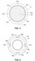
FIG. 4 is a cross-sectional view taken along a plane corresponding to the line IV-IV inFIG. 2 . -
FIG. 5 is a diagram of a pressure receiving pin as viewed from the collar side in the axial direction. -
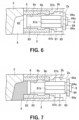
FIG. 6 is an enlarged cross-sectional view showing the pressure receiving pin and an area around the pressure receiving pin in an enlarged manner, and shows a state in which a fixed mold and a movable mold are clamped. -
FIG. 7 is an enlarged cross-sectional view showing the pressure receiving pin and the area around the pressure receiving pin in an enlarged manner, and shows a state in which the pressure receiving pin is pushed up by molten metal. -
FIG. 8 is an enlarged cross-sectional view showing the pressure receiving pin and the area around the pressure receiving pin in an enlarged manner, and shows a state in which the fixed mold and the movable mold are opened. - Hereinafter, an exemplary embodiment will be described in detail with reference to drawings. All of the features as shown in the drawings may not necessarily be essential.
-
FIG. 1 shows a basic configuration of a die casting mold 31 (hereinafter simply referred to as "mold 31") provided with a mold degassing apparatus 1 (i.e., a degassing apparatus for a mold) according to this embodiment, andFIG. 2 andFIG. 3 show the detail of themold degassing apparatus 1. - The
mold 31 includes a fixedmain mold 32 and a movablemain mold 33 that moves in the direction approaching or separating from the fixed main mold 32 (in the left-right direction inFIG. 1 ). - The fixed
main mold 32 may be provided with a fixedcavity mold 34. The movablemain mold 33 may be provided with amovable cavity mold 35 such that themovable cavity mold 35 moves together with the movablemain mold 33. - A mating surface between the fixed
cavity mold 34 and themovable cavity mold 35 has acavity 36 for forming a cast product (an aluminum cast product, a magnesium cast product, or the like). - The fixed
main mold 32 may have aninjection sleeve 38 that communicates with thecavity 36, and aninjection piston 39 may be fitted and inserted in theinjection sleeve 38. Molten metal (aluminum molten metal, magnesium molten metal, or the like) in theinjection sleeve 38 may be extruded by theinjection piston 39, thus being filled into thecavity 36. - The movable
main mold 33 may be provided with apressing plate 41 and anextrusion pin 42. After a cast product is formed in thecavity 36 and themold 31 is opened, thepressing plate 41 and theextrusion pin 42 are used for pushing out the cast product. - The
mold degassing apparatus 1 may be provided on the side (the upper side inFIG. 1 ) opposite to the side (the lower side inFIG. 1 ) on which molten metal is filled, with thecavity 36 interposed therebetween. - The
mold degassing apparatus 1 includes a fixedmold 2, which is provided to the fixedmain mold 32, and amovable mold 3, which is provided to the movablemain mold 33 and which moves together with the movablemain mold 33. - The
movable mold 3 is movable in the direction approaching or separating from the fixed mold 2 (in the left-right direction inFIG. 1 , and in the up-down direction inFIG. 2 andFIG. 3 ). - A mating surface between the fixed
mold 2 and themovable mold 3 has anexhaust passage 4 that communicates with thecavity 36 to discharge gas in thecavity 36. - In the present embodiment, the intermediate portion of the
exhaust passage 4 in the length direction is formed on the mating surface between the fixedmold 2 and themovable mold 3. The portion of theexhaust passage 4 on a cavity side (inlet side) is formed on the mating surface between the fixedcavity mold 34 and themovable cavity mold 35, and is connected to thecavity 36. - In contrast, the portion of the
exhaust passage 4 on the outlet side may be formed in avalve bush 13, which will be described later, and in the fixedmold 2. The outlet of theexhaust passage 4 may be connected to asuction device 5 that suctions gas in thecavity 36. - The portion of the
exhaust passage 4 that is formed in themovable mold 3 extends from the inlet side (the right side inFIG. 2 andFIG. 3 ) to a position that faces the distal end surface of apressure receiving pin 8, which will be described later, and, thereafter, passes through the viewer's side and the back side of the paper surface on whichFIG. 2 orFIG. 3 is shown (makes a detour), and then reaches a position that faces avalve body portion 12a of a closingvalve 12, which will be described later. - The
mold degassing apparatus 1 includes thepressure receiving pin 8 and the closingvalve 12, thepressure receiving pin 8 being provided on the inlet side (the right side inFIG. 2 andFIG. 3 ) of theexhaust passage 4 in the fixedmold 2, the closingvalve 12 being provided on the outlet side (the left side inFIG. 2 andFIG. 3 ) of theexhaust passage 4 in the fixedmold 2. - The
pressure receiving pin 8 may be provided such that the center axis of thepressure receiving pin 8 extends in the direction perpendicular or substantially perpendicular to the mating surface between the fixedmold 2 and themovable mold 3, and thepressure receiving pin 8 is slidable toward the exhaust passage 4 (toward the movable mold 3) and toward the side opposite to the exhaust passage 4 (toward the side opposite to the movable mold 3) in the above-mentioned direction. - The
pressure receiving pin 8 is disposed in a throughhole 2a (seeFIG. 6 or the like) provided in the fixedmold 2. - A portion of the through
hole 2a may be formed by afitting hole 9a that penetrates through the center portion of apin bush 9, which is fixed to the fixedmold 2 and having a cylindrical shape, toward theexhaust passage 4. - The
pressure receiving pin 8 includes afitting portion 81, adistal end portion 82, and anintermediate portion 83, thefitting portion 81 fitting in thefitting hole 9a, thedistal end portion 82 being located at a position closer to theexhaust passage 4 than thefitting portion 81 in the axial direction and having a columnar shape, theintermediate portion 83 being located between thefitting portion 81 and thedistal end portion 82 in the axial direction, having a diameter smaller than the diameter of thedistal end portion 82, and having a columnar shape. - The
pressure receiving pin 8 may also include acollar portion 84 and a small diameter portion (or a reduced diameter portion) 85, thecollar portion 84 being located on the side opposite to theexhaust passage 4 with respect to thefitting portion 81 and having a diameter larger than the largest diameter of thefitting portion 81, thesmall diameter portion 85 being provided between thefitting portion 81 and thecollar portion 84, and having a radius set to be slightly smaller than the shortest distance from the center axis of thepressure receiving pin 8 to agroove portion 81b, which will be described later, of thefitting portion 81. - The
fitting portion 81, thedistal end portion 82, theintermediate portion 83, thecollar portion 84, and thesmall diameter portion 85 may be disposed coaxially. - The
pressure receiving pin 8, particularly, thefitting portion 81 and thedistal end portion 82 slide with respect to thefitting hole 9a of thepin bush 9. - When molten metal that flows into the
exhaust passage 4 comes into contact with the surface of thedistal end portion 82 on theexhaust passage 4 side and the molten metal presses thepressure receiving pin 8 toward the side opposite to theexhaust passage 4 by the flow pressure of the molten metal, thepressure receiving pin 8 slides toward the side opposite to theexhaust passage 4 along the axial direction. - The diameter, particularly the largest diameter of the
fitting portion 81 and the diameter of thedistal end portion 82 may be equal to each other. Particularly, thefitting portion 81 and thedistal end portion 82 may slide with respect to the inner peripheral surface of thefitting hole 9a of thepin bush 9 with a predetermined clearance. - The predetermined clearance is set to a value that allows the
pressure receiving pin 8 to smoothly slide without causing looseness. - The predetermined clearance may be set to a range from about 0.01 mm to about 0.025 mm or from 0.01 mm to 0.025 mm, for example.
- As shown in
FIG. 4 , thefitting portion 81 may include slidingportions 81a and thegroove portions 81b. Particularly, the slidingportions 81a is capable of sliding with respect to thefitting hole 9a. Further particularly, thegroove portions 81b extends in the axial direction of thepressure receiving pin 8 and forms gaps larger than the predetermined clearance with respect to the inner peripheral surface of thefitting hole 9a. - A plurality of (e.g., four in this embodiment)
groove portions 81b are provided, and are formed at equal intervals in the circumferential direction of thefitting portion 81. Eachgroove portion 81b is formed by cutting a portion of the outer peripheral portion of a column into a flat shape. - The
distal end portion 82 is configured such that, as shown inFIG. 2 andFIG. 3 , in a state in which the fixedmold 2 and themovable mold 3 are clamped, thedistal end portion 82 is pressed by a portion of themovable mold 3, so that the distal end surface of thedistal end portion 82 is coplanar with the mating surface between the fixedmold 2 and themovable mold 3. - In contrast, when the fixed
mold 2 and themovable mold 3 are opened, thepressure receiving pin 8 moves toward themovable mold 3, so that the entiredistal end portion 82 may be exposed at a position closer to themovable mold 3 than the surface of the fixedmold 2 on themovable mold 3 side (seeFIG. 8 ). - In other words, the length of the
distal end portion 82 in the axial direction may be set to a length that allows the entiredistal end portion 82 to be exposed at the position closer to themovable mold 3 than the surface of the fixedmold 2 on themovable mold 3 side when the fixedmold 2 and themovable mold 3 are opened. - The
intermediate portion 83 may have a diameter smaller than the diameters of thefitting portion 81 and thedistal end portion 82, thus forming a gap larger than the predetermined clearance between theintermediate portion 83 and the inner peripheral surface of thefitting hole 9a. With the formation of this gap, it is possible to reduce sliding friction of the pressure receiving pin as much as possible. - The
collar portion 84 may be a portion that restricts the movement of thepressure receiving pin 8 in the axial direction in order to prevent thepressure receiving pin 8 from falling off from the fixedmold 2 when the fixedmold 2 and themovable mold 3 are opened. - Particularly, a step portion is provided at the end portion of the through
hole 2a of the fixedmold 2 on the side opposite to theexhaust passage 4, the step portion including acontact portion 2b (seeFIG. 6 or the like) with which thecollar portion 84 comes into contact when thepressure receiving pin 8 moves toward themovable mold 3. - The
collar portion 84 may come into contact with thecontact portion 2b when thepressure receiving pin 8 slides toward themovable mold 3 at the time of opening the mold. When thecollar portion 84 is in contact with thecontact portion 2b, thepressure receiving pin 8 is prevented from sliding toward themovable mold 3 from the position at which thecollar portion 84 is in contact with thecontact portion 2b. The depth of the step portion may be set to be larger than the length of thedistal end portion 82 in the axial direction. With such a configuration, when thepressure receiving pin 8 moves toward themovable mold 3 due to the opening of the mold, the entiredistal end portion 82 can be exposed at a position closer to themovable mold 3 than the surface of the fixedmold 2 on themovable mold 3 side. - As shown in
FIG. 5 , thecollar portion 84 may include, as viewed from the side opposite to theexhaust passage 4 in the axial direction,depression portions 84a that communicate with the gap formed between the outer peripheral surface of thesmall diameter portion 85 and the inner peripheral surface of the throughhole 2a. - A plurality of (e.g., four in this embodiment)
depression portions 84a may be provided, and are disposed at positions that overlap with thegroove portions 81b as viewed from the side opposite to theexhaust passage 4 in the axial direction. - The
respective depression portions 84a may be arranged at equal intervals in the circumferential direction of thecollar portion 84. The depth of eachdepression portion 84a may be set to a depth that allows the deepest portion to reach the outer peripheral surface of thesmall diameter portion 85. That is, the deepest portion of eachdepression portion 84a may be located at a position closer to the center axis of thepressure receiving pin 8 than the bottom portion of thegroove portion 81b of thefitting portion 81. - A
large diameter portion 9b may be formed on the inner peripheral surface of thefitting hole 9a of thepin bush 9 at the intermediate portion in the axial direction of the bush, thelarge diameter portion 9b having an inner diameter larger than the inner diameters of other portions. With the formation of thelarge diameter portion 9b, it is possible to reduce sliding friction of thepressure receiving pin 8 as much as possible. - In the same manner as the
pressure receiving pin 8, the closingvalve 12 may extend in the direction perpendicular or substantially perpendicular to the mating surface between the fixedmold 2 and themovable mold 3. - The closing
valve 12 may include thevalve body portion 12a, having a disc shape, at the end portion on themovable mold 3 side in the axial direction of the closingvalve 12, and include a slidingportion 12b at the intermediate portion in the axial direction of the closingvalve 12, the slidingportion 12b being fitted in and sliding within a throughhole 13a that penetrates through the center portion of thevalve bush 13 fixed to the fixedmold 2 and having a cylindrical shape. With the sliding of the slidingportion 12b, the closingvalve 12 slides toward themovable mold 3 and toward the side opposite to themovable mold 3 in the axial direction of the closingvalve 12. - The portion of the through
hole 13a of thevalve bush 13 on the side close to themovable mold 3 may form a portion of theexhaust passage 4, and may be connected to the outlet of the exhaust passage 4 (the suction device 5) through acommunication hole 13b, which is formed in the peripheral side surface of thevalve bush 13, and through the portion of theexhaust passage 4 that is formed in the fixedmold 2. - The opening end of the through
hole 13a of thevalve bush 13 on the side close to themovable mold 3 is connected to the portion of theexhaust passage 4 that faces thevalve body portion 12a. - The
valve body portion 12a is configured to close the opening end of the throughhole 13a of thevalve bush 13 on the side close to the movable mold 3 (that is, to close the exhaust passage 4) when the closingvalve 12 slides toward the side opposite to themovable mold 3. - The
valve body portion 12a is configured to open the above-mentioned opening end (that is, to open the exhaust passage 4) when the closingvalve 12 slides toward themovable mold 3. - The portion of the closing
valve 12 that is located in theexhaust passage 4 formed by the throughhole 13a may have a shape in which a cylinder, having an outer diameter substantially equal to the inner diameter of the throughhole 13a, has notchedportions 12c formed at three positions in the circumferential direction of the cylinder. - A space formed between each notched
portion 12c and the inner peripheral surface of the throughhole 13a may form theexhaust passage 4. InFIG. 2 andFIG. 3 , of the notchedportions 12c formed at three positions, only the notchedportions 12c formed at two positions can be seen. The remaining one position is disposed on the back side of the paper surface on whichFIG. 2 andFIG. 3 is shown, thus cannot be seen. - The closing
valve 12 is configured to close theexhaust passage 4 via an interlockinglever 15 due to the sliding of thepressure receiving pin 8 toward the side opposite to theexhaust passage 4. - Specifically, the interlocking
lever 15 may be disposed in alever chamber 2c formed in the fixedmold 2 on the side opposite to theexhaust passage 4 with respect to thepressure receiving pin 8. - The interlocking
lever 15 may be configured to be capable of swinging (rotating) about a swingingshaft 16, which extends in the direction perpendicular to the plane including the center axis of thepressure receiving pin 8 and the center axis of the closing valve 12 (the direction perpendicular to the paper surface inFIG. 2 ). - The swinging
shaft 16 may be provided at a position closer to the inlet side of theexhaust passage 4 than thepressure receiving pin 8. The interlockinglever 15 may extend along the above-mentioned plane from the swingingshaft 16 to the position of an engagement recessedportion 12d, which will be described later, of the closingvalve 12. - The distal end portion of the interlocking
lever 15 may engage with the engagement recessedportion 12d, which is provided on the peripheral side surface of the closingvalve 12 at a position in the vicinity of the end portion on the side opposite to themovable mold 3 in the axial direction of the closingvalve 12. - The intermediate portion of the interlocking
lever 15 in the length direction and the rear end surface of thepressure receiving pin 8 may have a positional relationship in which the intermediate portion of the interlockinglever 15 and the rear end surface of thepressure receiving pin 8 can come into contact with each other. - In the state in which the
mold 31 is opened, the interlockinglever 15 is urged in the counterclockwise direction inFIG. 2 about the swingingshaft 16 by acompression spring 17 via apressing plate 18 extending in the direction perpendicular to the above-mentioned plane. With such an operation, the rear end surface of thepressure receiving pin 8 is pressed by the interlockinglever 15, so that thepressure receiving pin 8 slides toward theexhaust passage 4. The closingvalve 12 slides toward themovable mold 3, thus opening theexhaust passage 4. - When the
mold 31 is brought into a clamped state (the state shown inFIG. 2 ) from such a state, thepressing plate 18 is pressed by themovable mold 3 toward the side opposite to themovable mold 3 against the urging force of thecompression spring 17 via apressing pin 19. With such an operation, the urging force of thecompression spring 17 stops acting on the interlockinglever 15. The force also stops acting on thepressure receiving pin 8 and the closingvalve 12 and hence, as shown inFIG. 2 , thepressure receiving pin 8 and the closingvalve 12 are located at positions pressed by the interlockinglever 15 as described above. That is, the closingvalve 12 is in a state of opening theexhaust passage 4. - As described above, when the
mold 31 is in a clamped state, thepressure receiving pin 8 is in a state of being pressed also by themovable mold 3 and hence, even when thepressure receiving pin 8 is pressed by the interlockinglever 15, thepressure receiving pin 8 does not move toward theexhaust passage 4. - After the
mold 31 is brought into a clamped state, molten metal is filled into thecavity 36 by theinjection piston 39. In filling the molten metal into thecavity 36, thesuction device 5 is actuated, so that gas is discharged from thecavity 36 through theexhaust passage 4. - After the molten metal is filled into the
cavity 36, the molten metal flows into theexhaust passage 4. This molten metal reaches the position that faces the distal end surface of thepressure receiving pin 8, and thepressure receiving pin 8 slides toward the side opposite to theexhaust passage 4 due to the flow pressure of the molten metal. - Due to the sliding of the
pressure receiving pin 8, the intermediate portion of the interlockinglever 15 in the length direction is pressed by the rear end surface of thepressure receiving pin 8 toward the side opposite to themovable mold 3. With such an operation, as shown inFIG. 3 , the interlockinglever 15 rotates in the clockwise direction about the swingingshaft 16. - Due to the rotation of the interlocking
lever 15, the closingvalve 12 slides toward the side opposite to themovable mold 3, thus closing theexhaust passage 4. Simultaneously with such a closing operation of the closingvalve 12, the molten metal flows toward the position that faces thevalve body portion 12a of the closingvalve 12 from the position that faces the distal end surface of thepressure receiving pin 8. - However, because of the detouring of the
exhaust passage 4, the closingvalve 12 closes theexhaust passage 4 before the molten metal reaches the position that faces thevalve body portion 12a. With such a configuration, the molten metal that flows into theexhaust passage 4 is prevented from flowing to the portions of theexhaust passage 4 downstream of thevalve body portion 12a of the closing valve 12 (subsequently, to the suction device 5). - The predetermined clearance is formed between the outer peripheral surface of the
pressure receiving pin 8 and the inner peripheral surface of thefitting hole 9a of thepin bush 9, particularly, between thedistal end portion 82 and the inner peripheral surface of thefitting hole 9a, and hence, a foreign substance, such as cavity lubricating oil or molten metal, may enter the clearance portion. When a large number of cast products are continued to be repeatedly casted with the cavity, thepressure receiving pin 8 eventually becomes less likely to slide due to the foreign substance that enters the clearance portion, so that there is a concern that it becomes impossible to close theexhaust passage 4 with the closingvalve 12. Particularly, a foreign substance that passes through the clearance portion is likely to remain at thedistal end portion 82 and theintermediate portion 83 of thepressure receiving pin 8, thus easily causing sliding failure of thepressure receiving pin 8. - In view of the above, in the present embodiment, when the fixed
mold 2 and themovable mold 3 are opened, air is supplied to the space formed between the inner peripheral surface of the throughhole 2a and the outer peripheral surface of thepressure receiving pin 8 to remove a foreign substance. - As shown in
FIG. 2 andFIG. 3 , anair supply passage 60 may be formed in the fixedmold 2 on the side opposite to theexhaust passage 4 with respect to a portion at which the closingvalve 12 is disposed. - As shown in
FIG. 1 , anair supply device 6 is provided at the inlet of the air supply passage 60 (on the upper side inFIG. 1 , on the left side inFIG. 2 andFIG. 3 ). Air supplied from theair supply device 6 passes through the gap formed between the slidingportion 12b of the closingvalve 12 and the fixedmold 2 and enters thelever chamber 2c and, thereafter, enters a space formed between the inner peripheral surface of the throughhole 2a and the outer peripheral surface of thepressure receiving pin 8 from the side opposite to theexhaust passage 4. Then, the air passes through thedepression portions 84a and thegroove portions 81b and enters the space formed between the outer peripheral surface of thepressure receiving pin 8 and the inner peripheral surface of thefitting hole 9a and, thereafter, flows out to themovable mold 3. With such a configuration, a foreign substance in the space formed between the inner peripheral surface of thefitting hole 9a and thedistal end portion 82 or in the space formed between the inner peripheral surface of thefitting hole 9a and theintermediate portion 83 is discharged toward themovable mold 3 by the flow pressure of the air. - Next, a series of operations of the
pressure receiving pin 8 will be described with reference toFIG. 6 to FIG. 8 . - First, as shown in
FIG. 6 , in a state in which the fixedmold 2 and themovable mold 3 are clamped, thepressure receiving pin 8 is pressed by the portion of themovable mold 3, thus sliding toward the side opposite to theexhaust passage 4. At this point of operation, the distal end surface of thedistal end portion 82 may be coplanar with the mating surface between the fixedmold 2 and themovable mold 3. - When molten metal is supplied from the state shown in
FIG. 6 , as shown inFIG. 7 , thepressure receiving pin 8 slides toward the side opposite to theexhaust passage 4 due to the flow pressure of the molten metal. At this point of operation, a slight amount of foreign substance may intrude from the clearance portion formed between the outer peripheral portion of thedistal end portion 82 and the inner peripheral surface of thefitting hole 9a. - When cooling of the molten metal is completed from the state shown in
FIG. 7 and the fixedmold 2 and themovable mold 3 are opened, the interlockinglever 15 is pressed by thecompression spring 17, thus being rotated, so that thepressure receiving pin 8 slides toward theexhaust passage 4. - After the lapse of a predetermined time from the starting of opening of the mold, as shown in
FIG. 8 , the entiredistal end portion 82 is located at a position closer to themovable mold 3 than the surface of the fixedmold 2 on themovable mold 3 side. With such an operation, a relatively large gap is formed between the end portion of the throughhole 2a on themovable mold 3 side and thepressure receiving pin 8. Theair supply device 6 is actuated at this timing, so that air is supplied into the fixedmold 2. The predetermined time is about 5 seconds or 5 seconds, for example. An air supply time is about 5 seconds or 5 seconds, for example. The air supply timing and the air supply time are controlled by a control device not shown in the drawing, and may be suitably set by a worker. - The air that enters the
lever chamber 2c through theair supply passage 60 may intrude into a space formed between the outer peripheral surface of thesmall diameter portion 85 and the inner peripheral surface of the throughhole 2a from thedepression portions 84a of thecollar portion 84. - The
depression portions 84a and thegroove portions 81b of thefitting portion 81 overlap with each other in the axial direction of thepressure receiving pin 8 and hence, the air passes through thegroove portions 81b and intrudes into the space formed between the outer peripheral surface of theintermediate portion 83 and the inner peripheral surface of thefitting hole 9a. - The air that intrudes into the space formed between the outer peripheral surface of the
intermediate portion 83 and the inner peripheral surface of thefitting hole 9a spreads around theintermediate portion 83 and, thereafter, passes through the space formed between thedistal end portion 82 and the fixedmold 2 toward themovable mold 3. - Due to the flow pressure of the air at this point of operation, a foreign substance in the space formed between the inner peripheral surface of the
fitting hole 9a and thedistal end portion 82 or in the space formed between the inner peripheral surface of thefitting hole 9a and theintermediate portion 83 is discharged toward themovable mold 3. - As described above, the deepest portion of each
depression portion 84a is located at the position closer to the center axis of thepressure receiving pin 8 than the bottom portion of thegroove portion 81b of thefitting portion 81 and hence, even when thecollar portion 84 comes into contact with the lockingportion 2b, air can pass through thedepression portions 84a and thegroove portions 81b. Therefore, after the lapse of a predetermined time from the starting of opening of the mold, a state is always maintained in which air can pass through the space toward themovable mold 3. - Accordingly, according to this embodiment, the
pressure receiving pin 8 of themold degassing apparatus 1 includes thefitting portion 81 that fits in the throughhole 2a provided in the fixedmold 2 and communicating with the portion of theexhaust passage 4 on the inlet side, thedistal end portion 82 that is located coaxially with thefitting portion 81 at a position closer to theexhaust passage 4 than thefitting portion 81, that slides with respect to the throughhole 2a upon reception of molten metal, and that has a columnar shape, and theintermediate portion 83 that is located coaxially with thefitting portion 81 and thedistal end portion 82 at a position between thefitting portion 81 and thedistal end portion 82 and that has a diameter smaller than the diameter of thedistal end portion 82. - The
mold degassing apparatus 1 further includes theair supply device 6 that supplies air at the time of opening themovable mold 3 such that the air passes through the gap formed between the outer peripheral surface of theintermediate portion 83 and the inner peripheral surface of the throughhole 2a and the gap formed between thedistal end portion 82 and the fixedmold 2, and flows out to themovable mold 3. - With such a configuration, even when a foreign substance enters the space formed between the outer peripheral surface of the
pressure receiving pin 8 and the inner peripheral surface of the throughhole 2a during casting, it is possible to discharge the foreign substance by the flow pressure of the air. Particularly, theintermediate portion 83 having a diameter smaller than the diameter of thedistal end portion 82 is provided on the side opposite to the exhaust passage with respect to thedistal end portion 82 and hence, air supplied to theintermediate portion 83 spreads over the entireintermediate portion 83 in the circumferential direction and, thereafter, flows out to themovable mold 3. Therefore, it is possible to supply air to the entire portion of the throughhole 2a on the side close to themovable mold 3, where a foreign substance is particularly liable to enter. As a result, it is possible to suppress deterioration of the slidability of thepressure receiving pin 8 as much as possible. - In the present embodiment, the
fitting portion 81 includes the slidingportions 81a that slide with respect to the inner peripheral surface of the throughhole 2a with a predetermined clearance, and thegroove portions 81b that extend in the axial direction of thepressure receiving pin 8 and that form gaps between thegroove portions 81b and the inner peripheral surface of the throughhole 2a, each gap being larger than the predetermined clearance, and theair supply device 6 is configured to supply air into the gap formed between the outer peripheral surface of theintermediate portion 83 and the inner peripheral surface of the throughhole 2a through thegroove portions 81b at the time of opening themovable mold 3. - With such a configuration, air is supplied from the
groove portions 81b that are located on the side opposite to theexhaust passage 4 with respect to theintermediate portion 83 of thepressure receiving pin 8 in the axial direction and hence, it is possible to supply air to the entireintermediate portion 83 in the axial direction. Further, air is supplied to theintermediate portion 83 through thegroove portions 81b and hence, it is possible to increase the flow of air flowing from theintermediate portion 83 toward thedistal end portion 82 as much as possible. As a result, a foreign substance can be more effectively discharged and hence, it is possible to suppress deterioration of the slidability of thepressure receiving pin 8 as much as possible. - In the present embodiment, the
air supply device 6 is configured to supply air from the side opposite to the exhaust passage with respect to thefitting portion 81. - With such a configuration, air can be caused to pass over the entire
pressure receiving pin 8 in the axial direction and hence, it is possible to effectively remove a foreign substance. As a result, it is possible to more effectively suppress deterioration of the slidability of thepressure receiving pin 8. - In the present embodiment, the
pressure receiving pin 8 includes thecollar portion 84 that is located on the side opposite to theexhaust passage 4 with respect to thefitting portion 81, and that has a diameter larger than the largest diameter of thefitting portion 81, and thesmall diameter portion 85 that is provided between thefitting portion 81 and thecollar portion 84, and that has a radius set to be equal to or less than the shortest distance from the center axis of thepressure receiving pin 8 to thegroove portion 81b of thefitting portion 81. Thecollar portion 84 includes thedepression portions 84a that communicate with the gap formed between the outer peripheral surface of thesmall diameter portion 85 and the inner peripheral surface of the throughhole 2a as viewed from the side opposite to theexhaust passage 4 in the axial direction. - With such a configuration, the
depression portions 84a are provided and hence, even when thecollar portion 84 having a diameter larger than the diameter of thefitting portion 81 is provided, it is possible to cause air to appropriately flow into the space formed between the outer peripheral surface of thesmall diameter portion 85 and the inner peripheral surface of the throughhole 2a. The air that flows into the space from thedepression portions 84a spreads in the space formed between the outer peripheral surface of thesmall diameter portion 85 and the inner peripheral surface of the throughhole 2a, and then flows into thegroove portions 81b. Thus, even when there is some degree of positional displacement between thedepression portions 84a and thegroove portions 81b in the circumferential direction of thepressure receiving pin 8, it is possible to cause air to appropriately flow into thegroove portions 81b. Therefore, it is possible to more effectively suppress deterioration of the slidability of thepressure receiving pin 8. - In the present embodiment, the plurality of
groove portions 81b are provided, and are formed at intervals in the circumferential direction of thefitting portion 81, and the plurality ofdepression portions 84a are provided, and are disposed at positions that overlap with therespective groove portions 81b as viewed from the side opposite to theexhaust passage 4 in the axial direction of thepressure receiving pin 8. With such a configuration, the plurality ofgroove portions 81b and the plurality ofdepression portions 84a are provided and hence, air can be caused to flow effectively. Further, the positions of thegroove portions 81b and the positions of thedepression portions 84a overlap with each other as viewed from the side opposite to theexhaust passage 4 in the axial direction and hence, air flows easily. As a result, it is possible to more effectively suppress deterioration of the slidability of thepressure receiving pin 8. - In the present embodiment, the plurality of
groove portions 81b are provided, and are formed at equal intervals in the circumferential direction of thefitting portion 81. With such a configuration, it is possible to cause air to uniformly flow through the space formed between the outer peripheral surface of thepressure receiving pin 8 and the inner peripheral surface of the throughhole 2a and hence, uneven distribution of foreign substances caused by uneven air flow rate can be suppressed. As a result, it is possible to more effectively suppress deterioration of the slidability of thepressure receiving pin 8. - In the present embodiment, the outer diameter of the
distal end portion 82 is equal to the largest diameter of thefitting portion 81. - With such a configuration, the gap formed between the outer peripheral surface of the
distal end portion 82 and the inner peripheral surface of the throughhole 2a can be narrowed as much as possible and hence, it is possible to suppress entrance of a foreign substance into the gap. Even if a foreign substance enters the gap, it is possible to discharge the foreign substance by air. Accordingly, it is possible to more effectively suppress deterioration of the slidability of thepressure receiving pin 8. - In the present embodiment, the step portion is provided to the fixed
mold 2, the step portion including thecontact portion 2b with which thecollar portion 84 comes into contact when thepressure receiving pin 8 moves toward themovable mold 3 due to opening of the fixedmold 2 and themovable mold 3, and the depth of the step portion is set to be larger than the length of thedistal end portion 82 in the axial direction of thepressure receiving pin 8. - With such a configuration, when the
pressure receiving pin 8 moves toward themovable mold 3 due to opening of the mold, the entiredistal end portion 82 can be exposed at the position closer to themovable mold 3 than the surface of the fixedmold 2 on themovable mold 3 side. As a result, it is possible to discharge a foreign substance with high efficiency by causing air to efficiently pass through the space toward themovable mold 3. - The technique disclosed in the present embodiment is not limited to the above-described embodiment, and substitutions may be made without departing from Claims.
- For example, in the above-described embodiment, the
air supply device 6 is configured to supply air from the side opposite to the exhaust passage with respect to thefitting portion 81. However, the configuration is not limited to the above. Provided that air can be supplied such that the air passes through the gap formed between the outer peripheral surface of theintermediate portion 83 and the inner peripheral surface of the throughhole 2a and the gap formed between thedistal end portion 82 and the fixedmold 2 and, then, flows out to themovable mold 3, a configuration may be adopted in which air is supplied into the throughhole 2a from the intermediate portion of thepressure receiving pin 8 in the axial direction. Particularly, in the case of a configuration in which the fixedmold 2 is provided with an air supply passage that communicates with the gap formed between the outer peripheral surface of theintermediate portion 83 and the inner peripheral surface of the throughhole 2a, so that air supplied from theair supply device 6 can be directly supplied to the gap, it is not always necessary to provide thegroove portions 81b to thefitting portion 81. - In the above-described embodiment, the
respective depression portions 84a are disposed to overlap with therespective groove portions 81b of thepressure receiving pin 8 as viewed from the side opposite to theexhaust passage 4 in the axial direction of thepressure receiving pin 8. However, the configuration is not limited to the above, and it is not always necessary for therespective depression portions 84a to overlap with therespective groove portions 81b of thepressure receiving pin 8 as viewed from the side opposite to theexhaust passage 4 in the axial direction of thepressure receiving pin 8. Even when the positions of therespective depression portions 84a are displaced from therespective groove portions 81b in the circumferential direction of thepressure receiving pin 8, thesmall diameter portion 85 is disposed between thefitting portion 81 and thecollar portion 84 and hence, air that flows into the gap formed between the outer peripheral surface of thesmall diameter portion 85 and the inner peripheral surface of the throughhole 2a through therespective depression portions 84a spreads in the gap and, thereafter, flows into the gap formed between the outer peripheral surface of theintermediate portion 83 and the inner peripheral surface of the throughhole 2a through therespective groove portions 81b. Therefore, a foreign substance that intrudes into the space formed between the outer peripheral surface of the pressure receiving pin and the inner peripheral surface of the hole portion can be removed without any problem. - The above-described embodiment is merely for example, and the scope of the present disclosure should not be considered limiting. The scope of the present disclosure is defined by Claims, and all modifications and changes belonging to the equivalent range of Claims fall within a range of the present disclosure.
- The technique disclosed herein is effective for a mold degassing apparatus used for discharging gas from a cavity of a mold for casting a cast product.
-
- 1
- mold degassing apparatus
- 2
- fixed mold
- 3
- movable mold
- 4
- exhaust passage
- 6
- air supply device
- 8
- pressure receiving pin
- 12
- closing valve
- 12b
- sliding portion
- 15
- interlocking lever
- 31
- mold
- 36
- cavity
- 81
- fitting portion
- 81a
- sliding portion
- 81b
- groove portion
- 82
- distal end portion
- 83
- intermediate portion
- 84
- collar portion
- 84a
- depression portion
- 85
- small diameter portion
Claims (12)
- A degassing apparatus (1) for a mold (31), the degassing apparatus comprising:a fixed mold (2);a movable mold (3);an exhaust passage (4) formed on a mating surface between the fixed mold (2) and the movable mold (3) and configured to communicate with a cavity (36) of the mold (31) ;a pressure receiving pin (8) provided on an inlet side of the exhaust passage (4) in the fixed mold (2) in such a way as to be slidable toward the exhaust passage (4) and toward a side opposite to the exhaust passage (4), and configured to slide toward the side opposite to the exhaust passage (4) due to a flow pressure of molten metal that flows into the exhaust passage (4); anda closing valve (12) provided on an outlet side of the exhaust passage (4) in the fixed mold (2), and configured to close the exhaust passage (4) via an interlocking lever (15) due to sliding of the pressure receiving pin (8) toward the side opposite to the exhaust passage (4),whereinthe pressure receiving pin (8) includesa fitting portion (81) that is configured to fit in a hole portion (2a) provided in the fixed mold (2) and communicate with a portion of the exhaust passage (4) on the inlet side,a distal end portion (82) that is configured to be located coaxially with the fitting portion (81) at a position closer to the exhaust passage (4) than the fitting portion (81), that is configured to slide with respect to the hole portion (2a) upon reception of the molten metal, and that has a columnar shape, andan intermediate portion (83) that is located coaxially with the fitting portion (81) and the distal end portion (82) at a position between the fitting portion (81) and the distal end portion (82) and that has a diameter smaller than a diameter of the distal end portion (82), andthe degassing apparatus (1) further comprises an air supply device (6) that is configured to supply air at a time of opening the movable mold (3) such that the air passes through a gap formed between an outer peripheral surface of the intermediate portion (83) and an inner peripheral surface of the hole portion (2a) and a gap formed between the distal end portion (82) and the fixed mold (2) and flows out to the movable mold (3).
- The degassing apparatus (1) according to claim 1, wherein
the fitting portion (81) includesa sliding portion (81a) that is configured to slide with respect to the inner peripheral surface of the hole portion (2a) with a predetermined clearance, anda groove portion (81b) that extends in an axial direction of the pressure receiving pin (8) and that is configured to form a gap between the groove portion (81b) and the inner peripheral surface of the hole portion (2a), the gap being larger than the predetermined clearance. - The degassing apparatus (1) according to claim 2, wherein
the air supply device (6) is configured to supply air into the gap formed between the outer peripheral surface of the intermediate portion (83) and the inner peripheral surface of the hole portion (2a) through the groove portion (81b) at the time of opening the movable mold (3). - The degassing apparatus (1) according to claim 2 or 3, wherein
the air supply device (6) is configured to supply air from the side opposite to the exhaust passage (4) with respect to the fitting portion (81). - The degassing apparatus (1) according to any one of claims 2 to 4, wherein
the pressure receiving pin (8) further includes
a collar portion (84) that is located on the side opposite to the exhaust passage (4) with respect to the fitting portion (81), and that has a diameter larger than a largest diameter of the fitting portion (81). - The degassing apparatus (1) according to claim 5, wherein
the pressure receiving pin (8) further includes
a reduced diameter portion (85) that is provided between the fitting portion (81) and the collar portion (84), and that has a radius equal to or less than a shortest distance from a center axis of the pressure receiving pin (8) to the groove portion (81b) of the fitting portion (81). - The degassing apparatus (1) according to claim 6, wherein
the collar portion (84) includes a depression portion (84a) that is configured to communicate with a gap formed between an outer peripheral surface of the reduced diameter portion (85) and the inner peripheral surface of the hole portion (2a) as viewed from the side opposite to the exhaust passage (4) in the axial direction. - The degassing apparatus (1) according to claim 7, whereina plurality of the groove portions (81b) are provided, and are formed at intervals in a circumferential direction of the fitting portion (81), anda plurality of the depression portions (84a) are provided, and are configured to be disposed at positions that overlap with the plurality of the groove portions (81b) as viewed from the side opposite to the exhaust passage (4) in the axial direction.
- The degassing apparatus (1) according to claim 8, wherein
the plurality of the groove portions (81b) are formed at equal intervals in a circumferential direction of the fitting portion (81). - The degassing apparatus (1) according to any one of claims 2 to 7, wherein
a plurality of the groove portions (81b) are provided, and are formed at equal intervals in a circumferential direction of the fitting portion (81). - The degassing apparatus (1) according to any one of the preceding claims, wherein
an outer diameter of the distal end portion (82) is equal to a largest diameter of the fitting portion (81). - A mold (31) comprising the degassing apparatus (1) according to any one of the preceding claims.
Applications Claiming Priority (1)
| Application Number | Priority Date | Filing Date | Title |
|---|---|---|---|
| JP2022178179A JP2024067827A (en) | 2022-11-07 | 2022-11-07 | Mold degassing device |
Publications (2)
| Publication Number | Publication Date |
|---|---|
| EP4371682A1 true EP4371682A1 (en) | 2024-05-22 |
| EP4371682B1 EP4371682B1 (en) | 2024-11-27 |
Family
ID=88295683
Family Applications (1)
| Application Number | Title | Priority Date | Filing Date |
|---|---|---|---|
| EP23202000.8A Active EP4371682B1 (en) | 2022-11-07 | 2023-10-06 | Mold degassing apparatus |
Country Status (4)
| Country | Link |
|---|---|
| US (1) | US12343915B2 (en) |
| EP (1) | EP4371682B1 (en) |
| JP (1) | JP2024067827A (en) |
| CN (1) | CN117983776A (en) |
Citations (3)
| Publication number | Priority date | Publication date | Assignee | Title |
|---|---|---|---|---|
| JP2002144008A (en) * | 2000-11-02 | 2002-05-21 | Uogishi Seiki Kogyo Kk | Gas vent device for die |
| JP2003112232A (en) * | 2001-10-01 | 2003-04-15 | Dai:Kk | Gas vent device for die, and method for using the device |
| JP2019005792A (en) | 2017-06-28 | 2019-01-17 | マツダ株式会社 | Gas drainage device for mold |
Family Cites Families (1)
| Publication number | Priority date | Publication date | Assignee | Title |
|---|---|---|---|---|
| CN102794430B (en) * | 2011-08-29 | 2015-11-18 | 日本模具贸易株式会社 | A kind of compression mod exhaust apparatus |
-
2022
- 2022-11-07 JP JP2022178179A patent/JP2024067827A/en active Pending
-
2023
- 2023-09-18 CN CN202311201388.7A patent/CN117983776A/en active Pending
- 2023-10-06 EP EP23202000.8A patent/EP4371682B1/en active Active
- 2023-10-17 US US18/488,240 patent/US12343915B2/en active Active
Patent Citations (3)
| Publication number | Priority date | Publication date | Assignee | Title |
|---|---|---|---|---|
| JP2002144008A (en) * | 2000-11-02 | 2002-05-21 | Uogishi Seiki Kogyo Kk | Gas vent device for die |
| JP2003112232A (en) * | 2001-10-01 | 2003-04-15 | Dai:Kk | Gas vent device for die, and method for using the device |
| JP2019005792A (en) | 2017-06-28 | 2019-01-17 | マツダ株式会社 | Gas drainage device for mold |
Also Published As
| Publication number | Publication date |
|---|---|
| JP2024067827A (en) | 2024-05-17 |
| EP4371682B1 (en) | 2024-11-27 |
| US12343915B2 (en) | 2025-07-01 |
| US20240149511A1 (en) | 2024-05-09 |
| CN117983776A (en) | 2024-05-07 |
Similar Documents
| Publication | Publication Date | Title |
|---|---|---|
| EP4371682B1 (en) | Mold degassing apparatus | |
| PL231436B1 (en) | Valve device, preferably for venting die-casting moulds | |
| US20190060986A1 (en) | High-Pressure Die Casting Apparatus And Method | |
| US6871688B2 (en) | Apparatus and method for manufacturing die-cast product | |
| JP5717692B2 (en) | Valve device for vacuum die casting equipment | |
| JP4892536B2 (en) | Vacuum casting system | |
| JPH067977B2 (en) | Mold degassing device | |
| CN111212695A (en) | Casting device, method for manufacturing casting, and seal structure | |
| CN111940699A (en) | Feeding device and die casting machine | |
| JP4274482B2 (en) | Die casting equipment | |
| CN105436460B (en) | Device for measuring the pressure in a mold cavity of a casting mold, in particular a vacuum casting mold, which can be filled with a melt | |
| JP2014213372A (en) | Degassing device for die casting | |
| AU2018201026A1 (en) | Valve device for venting die-casting moulds | |
| JP6730822B2 (en) | Vacuum die casting equipment | |
| JP2000225453A (en) | Degassing device | |
| JP6614206B2 (en) | Mold venting device | |
| JPH0238068B2 (en) | ||
| JP7426320B2 (en) | die casting equipment | |
| CN1638895A (en) | Die cast mold | |
| CN115138820A (en) | Die for die casting | |
| JP2022076583A (en) | Degassing device for vacuum die casting | |
| JPH07328758A (en) | Device for lubricating squeeze pin | |
| JP4011507B2 (en) | Injection sleeve lubrication apparatus and injection sleeve lubrication method for horizontal injection die casting machine | |
| JP2013193145A (en) | Aluminum die-cast product and method for manufacturing the same | |
| JP2008068303A (en) | Molding apparatus, extrusion pin, and molding method |
Legal Events
| Date | Code | Title | Description |
|---|---|---|---|
| PUAI | Public reference made under article 153(3) epc to a published international application that has entered the european phase |
Free format text: ORIGINAL CODE: 0009012 |
|
| STAA | Information on the status of an ep patent application or granted ep patent |
Free format text: STATUS: THE APPLICATION HAS BEEN PUBLISHED |
|
| AK | Designated contracting states |
Kind code of ref document: A1 Designated state(s): AL AT BE BG CH CY CZ DE DK EE ES FI FR GB GR HR HU IE IS IT LI LT LU LV MC ME MK MT NL NO PL PT RO RS SE SI SK SM TR |
|
| STAA | Information on the status of an ep patent application or granted ep patent |
Free format text: STATUS: REQUEST FOR EXAMINATION WAS MADE |
|
| 17P | Request for examination filed |
Effective date: 20240606 |
|
| RBV | Designated contracting states (corrected) |
Designated state(s): AL AT BE BG CH CY CZ DE DK EE ES FI FR GB GR HR HU IE IS IT LI LT LU LV MC ME MK MT NL NO PL PT RO RS SE SI SK SM TR |
|
| GRAP | Despatch of communication of intention to grant a patent |
Free format text: ORIGINAL CODE: EPIDOSNIGR1 |
|
| STAA | Information on the status of an ep patent application or granted ep patent |
Free format text: STATUS: GRANT OF PATENT IS INTENDED |
|
| INTG | Intention to grant announced |
Effective date: 20240816 |
|
| GRAS | Grant fee paid |
Free format text: ORIGINAL CODE: EPIDOSNIGR3 |
|
| GRAA | (expected) grant |
Free format text: ORIGINAL CODE: 0009210 |
|
| STAA | Information on the status of an ep patent application or granted ep patent |
Free format text: STATUS: THE PATENT HAS BEEN GRANTED |
|
| AK | Designated contracting states |
Kind code of ref document: B1 Designated state(s): AL AT BE BG CH CY CZ DE DK EE ES FI FR GB GR HR HU IE IS IT LI LT LU LV MC ME MK MT NL NO PL PT RO RS SE SI SK SM TR |
|
| REG | Reference to a national code |
Ref country code: GB Ref legal event code: FG4D |
|
| REG | Reference to a national code |
Ref country code: CH Ref legal event code: EP |
|
| REG | Reference to a national code |
Ref country code: DE Ref legal event code: R096 Ref document number: 602023001177 Country of ref document: DE |
|
| REG | Reference to a national code |
Ref country code: IE Ref legal event code: FG4D |
|
| REG | Reference to a national code |
Ref country code: LT Ref legal event code: MG9D |
|
| REG | Reference to a national code |
Ref country code: NL Ref legal event code: MP Effective date: 20241127 |
|
| PG25 | Lapsed in a contracting state [announced via postgrant information from national office to epo] |
Ref country code: IS Free format text: LAPSE BECAUSE OF FAILURE TO SUBMIT A TRANSLATION OF THE DESCRIPTION OR TO PAY THE FEE WITHIN THE PRESCRIBED TIME-LIMIT Effective date: 20250327 Ref country code: PT Free format text: LAPSE BECAUSE OF FAILURE TO SUBMIT A TRANSLATION OF THE DESCRIPTION OR TO PAY THE FEE WITHIN THE PRESCRIBED TIME-LIMIT Effective date: 20250327 Ref country code: HR Free format text: LAPSE BECAUSE OF FAILURE TO SUBMIT A TRANSLATION OF THE DESCRIPTION OR TO PAY THE FEE WITHIN THE PRESCRIBED TIME-LIMIT Effective date: 20241127 |
|
| PG25 | Lapsed in a contracting state [announced via postgrant information from national office to epo] |
Ref country code: FI Free format text: LAPSE BECAUSE OF FAILURE TO SUBMIT A TRANSLATION OF THE DESCRIPTION OR TO PAY THE FEE WITHIN THE PRESCRIBED TIME-LIMIT Effective date: 20241127 Ref country code: NL Free format text: LAPSE BECAUSE OF FAILURE TO SUBMIT A TRANSLATION OF THE DESCRIPTION OR TO PAY THE FEE WITHIN THE PRESCRIBED TIME-LIMIT Effective date: 20241127 |
|
| REG | Reference to a national code |
Ref country code: AT Ref legal event code: MK05 Ref document number: 1745250 Country of ref document: AT Kind code of ref document: T Effective date: 20241127 |
|
| PG25 | Lapsed in a contracting state [announced via postgrant information from national office to epo] |
Ref country code: BG Free format text: LAPSE BECAUSE OF FAILURE TO SUBMIT A TRANSLATION OF THE DESCRIPTION OR TO PAY THE FEE WITHIN THE PRESCRIBED TIME-LIMIT Effective date: 20241127 |
|
| PG25 | Lapsed in a contracting state [announced via postgrant information from national office to epo] |
Ref country code: ES Free format text: LAPSE BECAUSE OF FAILURE TO SUBMIT A TRANSLATION OF THE DESCRIPTION OR TO PAY THE FEE WITHIN THE PRESCRIBED TIME-LIMIT Effective date: 20241127 |
|
| PG25 | Lapsed in a contracting state [announced via postgrant information from national office to epo] |
Ref country code: NO Free format text: LAPSE BECAUSE OF FAILURE TO SUBMIT A TRANSLATION OF THE DESCRIPTION OR TO PAY THE FEE WITHIN THE PRESCRIBED TIME-LIMIT Effective date: 20250227 |
|
| PG25 | Lapsed in a contracting state [announced via postgrant information from national office to epo] |
Ref country code: LV Free format text: LAPSE BECAUSE OF FAILURE TO SUBMIT A TRANSLATION OF THE DESCRIPTION OR TO PAY THE FEE WITHIN THE PRESCRIBED TIME-LIMIT Effective date: 20241127 Ref country code: GR Free format text: LAPSE BECAUSE OF FAILURE TO SUBMIT A TRANSLATION OF THE DESCRIPTION OR TO PAY THE FEE WITHIN THE PRESCRIBED TIME-LIMIT Effective date: 20250228 Ref country code: AT Free format text: LAPSE BECAUSE OF FAILURE TO SUBMIT A TRANSLATION OF THE DESCRIPTION OR TO PAY THE FEE WITHIN THE PRESCRIBED TIME-LIMIT Effective date: 20241127 |
|
| PG25 | Lapsed in a contracting state [announced via postgrant information from national office to epo] |
Ref country code: PL Free format text: LAPSE BECAUSE OF FAILURE TO SUBMIT A TRANSLATION OF THE DESCRIPTION OR TO PAY THE FEE WITHIN THE PRESCRIBED TIME-LIMIT Effective date: 20241127 |
|
| PG25 | Lapsed in a contracting state [announced via postgrant information from national office to epo] |
Ref country code: RS Free format text: LAPSE BECAUSE OF FAILURE TO SUBMIT A TRANSLATION OF THE DESCRIPTION OR TO PAY THE FEE WITHIN THE PRESCRIBED TIME-LIMIT Effective date: 20250227 |
|
| PG25 | Lapsed in a contracting state [announced via postgrant information from national office to epo] |
Ref country code: SM Free format text: LAPSE BECAUSE OF FAILURE TO SUBMIT A TRANSLATION OF THE DESCRIPTION OR TO PAY THE FEE WITHIN THE PRESCRIBED TIME-LIMIT Effective date: 20241127 |
|
| PG25 | Lapsed in a contracting state [announced via postgrant information from national office to epo] |
Ref country code: DK Free format text: LAPSE BECAUSE OF FAILURE TO SUBMIT A TRANSLATION OF THE DESCRIPTION OR TO PAY THE FEE WITHIN THE PRESCRIBED TIME-LIMIT Effective date: 20241127 |
|
| PG25 | Lapsed in a contracting state [announced via postgrant information from national office to epo] |
Ref country code: EE Free format text: LAPSE BECAUSE OF FAILURE TO SUBMIT A TRANSLATION OF THE DESCRIPTION OR TO PAY THE FEE WITHIN THE PRESCRIBED TIME-LIMIT Effective date: 20241127 |
|
| PG25 | Lapsed in a contracting state [announced via postgrant information from national office to epo] |
Ref country code: RO Free format text: LAPSE BECAUSE OF FAILURE TO SUBMIT A TRANSLATION OF THE DESCRIPTION OR TO PAY THE FEE WITHIN THE PRESCRIBED TIME-LIMIT Effective date: 20241127 |
|
| PG25 | Lapsed in a contracting state [announced via postgrant information from national office to epo] |
Ref country code: SK Free format text: LAPSE BECAUSE OF FAILURE TO SUBMIT A TRANSLATION OF THE DESCRIPTION OR TO PAY THE FEE WITHIN THE PRESCRIBED TIME-LIMIT Effective date: 20241127 |
|
| PG25 | Lapsed in a contracting state [announced via postgrant information from national office to epo] |
Ref country code: CZ Free format text: LAPSE BECAUSE OF FAILURE TO SUBMIT A TRANSLATION OF THE DESCRIPTION OR TO PAY THE FEE WITHIN THE PRESCRIBED TIME-LIMIT Effective date: 20241127 |
|
| PG25 | Lapsed in a contracting state [announced via postgrant information from national office to epo] |
Ref country code: IT Free format text: LAPSE BECAUSE OF FAILURE TO SUBMIT A TRANSLATION OF THE DESCRIPTION OR TO PAY THE FEE WITHIN THE PRESCRIBED TIME-LIMIT Effective date: 20241127 |
|
| REG | Reference to a national code |
Ref country code: DE Ref legal event code: R097 Ref document number: 602023001177 Country of ref document: DE |
|
| PG25 | Lapsed in a contracting state [announced via postgrant information from national office to epo] |
Ref country code: SE Free format text: LAPSE BECAUSE OF FAILURE TO SUBMIT A TRANSLATION OF THE DESCRIPTION OR TO PAY THE FEE WITHIN THE PRESCRIBED TIME-LIMIT Effective date: 20241127 |
|
| PLBE | No opposition filed within time limit |
Free format text: ORIGINAL CODE: 0009261 |
|
| STAA | Information on the status of an ep patent application or granted ep patent |
Free format text: STATUS: NO OPPOSITION FILED WITHIN TIME LIMIT |
|
| 26N | No opposition filed |
Effective date: 20250828 |
|
| PGFP | Annual fee paid to national office [announced via postgrant information from national office to epo] |
Ref country code: DE Payment date: 20250902 Year of fee payment: 3 |