EP4368858A1 - Electric work vehicle - Google Patents
Electric work vehicle Download PDFInfo
- Publication number
- EP4368858A1 EP4368858A1 EP23201104.9A EP23201104A EP4368858A1 EP 4368858 A1 EP4368858 A1 EP 4368858A1 EP 23201104 A EP23201104 A EP 23201104A EP 4368858 A1 EP4368858 A1 EP 4368858A1
- Authority
- EP
- European Patent Office
- Prior art keywords
- hole
- electric motor
- work vehicle
- travel
- lever
- Prior art date
- Legal status (The legal status is an assumption and is not a legal conclusion. Google has not performed a legal analysis and makes no representation as to the accuracy of the status listed.)
- Granted
Links
Images


Classifications
-
- B—PERFORMING OPERATIONS; TRANSPORTING
- B60—VEHICLES IN GENERAL
- B60L—PROPULSION OF ELECTRICALLY-PROPELLED VEHICLES; SUPPLYING ELECTRIC POWER FOR AUXILIARY EQUIPMENT OF ELECTRICALLY-PROPELLED VEHICLES; ELECTRODYNAMIC BRAKE SYSTEMS FOR VEHICLES IN GENERAL; MAGNETIC SUSPENSION OR LEVITATION FOR VEHICLES; MONITORING OPERATING VARIABLES OF ELECTRICALLY-PROPELLED VEHICLES; ELECTRIC SAFETY DEVICES FOR ELECTRICALLY-PROPELLED VEHICLES
- B60L15/00—Methods, circuits, or devices for controlling the traction-motor speed of electrically-propelled vehicles
- B60L15/20—Methods, circuits, or devices for controlling the traction-motor speed of electrically-propelled vehicles for control of the vehicle or its driving motor to achieve a desired performance, e.g. speed, torque, programmed variation of speed
- B60L15/2054—Methods, circuits, or devices for controlling the traction-motor speed of electrically-propelled vehicles for control of the vehicle or its driving motor to achieve a desired performance, e.g. speed, torque, programmed variation of speed by controlling transmissions or clutches
-
- F—MECHANICAL ENGINEERING; LIGHTING; HEATING; WEAPONS; BLASTING
- F16—ENGINEERING ELEMENTS AND UNITS; GENERAL MEASURES FOR PRODUCING AND MAINTAINING EFFECTIVE FUNCTIONING OF MACHINES OR INSTALLATIONS; THERMAL INSULATION IN GENERAL
- F16H—GEARING
- F16H63/00—Control outputs from the control unit to change-speed- or reversing-gearings for conveying rotary motion or to other devices than the final output mechanism
- F16H63/40—Control outputs from the control unit to change-speed- or reversing-gearings for conveying rotary motion or to other devices than the final output mechanism comprising signals other than signals for actuating the final output mechanisms
- F16H63/50—Signals to an engine or motor
-
- B—PERFORMING OPERATIONS; TRANSPORTING
- B60—VEHICLES IN GENERAL
- B60K—ARRANGEMENT OR MOUNTING OF PROPULSION UNITS OR OF TRANSMISSIONS IN VEHICLES; ARRANGEMENT OR MOUNTING OF PLURAL DIVERSE PRIME-MOVERS IN VEHICLES; AUXILIARY DRIVES FOR VEHICLES; INSTRUMENTATION OR DASHBOARDS FOR VEHICLES; ARRANGEMENTS IN CONNECTION WITH COOLING, AIR INTAKE, GAS EXHAUST OR FUEL SUPPLY OF PROPULSION UNITS IN VEHICLES
- B60K20/00—Arrangement or mounting of change-speed gearing control devices in vehicles
- B60K20/02—Arrangement or mounting of change-speed gearing control devices in vehicles of initiating means
-
- F—MECHANICAL ENGINEERING; LIGHTING; HEATING; WEAPONS; BLASTING
- F16—ENGINEERING ELEMENTS AND UNITS; GENERAL MEASURES FOR PRODUCING AND MAINTAINING EFFECTIVE FUNCTIONING OF MACHINES OR INSTALLATIONS; THERMAL INSULATION IN GENERAL
- F16H—GEARING
- F16H59/00—Control inputs to control units of change-speed- or reversing-gearings for conveying rotary motion
- F16H59/02—Selector apparatus
- F16H59/04—Ratio selector apparatus
- F16H59/044—Ratio selector apparatus consisting of electrical switches or sensors
-
- F—MECHANICAL ENGINEERING; LIGHTING; HEATING; WEAPONS; BLASTING
- F16—ENGINEERING ELEMENTS AND UNITS; GENERAL MEASURES FOR PRODUCING AND MAINTAINING EFFECTIVE FUNCTIONING OF MACHINES OR INSTALLATIONS; THERMAL INSULATION IN GENERAL
- F16H—GEARING
- F16H59/00—Control inputs to control units of change-speed- or reversing-gearings for conveying rotary motion
- F16H59/02—Selector apparatus
- F16H59/08—Range selector apparatus
- F16H59/10—Range selector apparatus comprising levers
- F16H59/105—Range selector apparatus comprising levers consisting of electrical switches or sensors
-
- F—MECHANICAL ENGINEERING; LIGHTING; HEATING; WEAPONS; BLASTING
- F16—ENGINEERING ELEMENTS AND UNITS; GENERAL MEASURES FOR PRODUCING AND MAINTAINING EFFECTIVE FUNCTIONING OF MACHINES OR INSTALLATIONS; THERMAL INSULATION IN GENERAL
- F16H—GEARING
- F16H61/00—Control functions within control units of change-speed- or reversing-gearings for conveying rotary motion ; Control of exclusively fluid gearing, friction gearing, gearings with endless flexible members or other particular types of gearing
- F16H61/02—Control functions within control units of change-speed- or reversing-gearings for conveying rotary motion ; Control of exclusively fluid gearing, friction gearing, gearings with endless flexible members or other particular types of gearing characterised by the signals used
- F16H61/0202—Control functions within control units of change-speed- or reversing-gearings for conveying rotary motion ; Control of exclusively fluid gearing, friction gearing, gearings with endless flexible members or other particular types of gearing characterised by the signals used the signals being electric
- F16H61/0248—Control units where shifting is directly initiated by the driver, e.g. semi-automatic transmissions
-
- B—PERFORMING OPERATIONS; TRANSPORTING
- B60—VEHICLES IN GENERAL
- B60K—ARRANGEMENT OR MOUNTING OF PROPULSION UNITS OR OF TRANSMISSIONS IN VEHICLES; ARRANGEMENT OR MOUNTING OF PLURAL DIVERSE PRIME-MOVERS IN VEHICLES; AUXILIARY DRIVES FOR VEHICLES; INSTRUMENTATION OR DASHBOARDS FOR VEHICLES; ARRANGEMENTS IN CONNECTION WITH COOLING, AIR INTAKE, GAS EXHAUST OR FUEL SUPPLY OF PROPULSION UNITS IN VEHICLES
- B60K1/00—Arrangement or mounting of electrical propulsion units
-
- B—PERFORMING OPERATIONS; TRANSPORTING
- B60—VEHICLES IN GENERAL
- B60Y—INDEXING SCHEME RELATING TO ASPECTS CROSS-CUTTING VEHICLE TECHNOLOGY
- B60Y2200/00—Type of vehicle
- B60Y2200/10—Road Vehicles
- B60Y2200/14—Trucks; Load vehicles, Busses
- B60Y2200/141—Light trucks
-
- B—PERFORMING OPERATIONS; TRANSPORTING
- B60—VEHICLES IN GENERAL
- B60Y—INDEXING SCHEME RELATING TO ASPECTS CROSS-CUTTING VEHICLE TECHNOLOGY
- B60Y2200/00—Type of vehicle
- B60Y2200/90—Vehicles comprising electric prime movers
- B60Y2200/91—Electric vehicles
-
- F—MECHANICAL ENGINEERING; LIGHTING; HEATING; WEAPONS; BLASTING
- F16—ENGINEERING ELEMENTS AND UNITS; GENERAL MEASURES FOR PRODUCING AND MAINTAINING EFFECTIVE FUNCTIONING OF MACHINES OR INSTALLATIONS; THERMAL INSULATION IN GENERAL
- F16H—GEARING
- F16H59/00—Control inputs to control units of change-speed- or reversing-gearings for conveying rotary motion
- F16H59/02—Selector apparatus
- F16H2059/026—Details or special features of the selector casing or lever support
Definitions
- the present invention relates to an electric work vehicle.
- an operator changes a shift level of a transmission while operating an operation tool as a means of varying a speed of a motive power inputted from an engine.
- the operator can change not only the shift level but also a direction of travel to either a front direction or a reverse direction by operating the operation tool.
- an electric motor has been increasingly employed in the work vehicle as a driving source instead of an engine. The electric motor is able to rotate in both a forward direction and a reverse direction.
- the conventional operation tool is merely configured to operate the transmission.
- the present invention provides an electric work vehicle which simplifies an operation for changing the direction of the rotation of the electric motor.
- An electric work vehicle including:
- an operator can change not only the shift level of the transmission but also the direction of the rotation of the electric motor by operating the single operation part. That is, the operator can switch a travel direction of the electric work vehicle between a forward travel and a reverse travel without an additional operation tool for changing the direction of the rotation of the electric motor. Therefore, an operation for changing the direction of the rotation of the electric motor is simplified in the electric work vehicle.
- the operator can change the shift level by operating the lever in the front-back direction and can switch the travel direction of the electric work vehicle between the forward travel and the reverse travel by operating the lever in the left-right direction. This enables the operator to operate the lever intuitively.
- the lever moves along the first hole when the operator operates the lever in the front-back direction.
- the lever moves along the second hole when the operator operates the lever in the left-right direction.
- This configuration enables the operator to cause the electric work vehicle traveling forward by operating the lever forward or backward from the neutral position and to cause the electric work vehicle traveling backward by operating the lever leftward or rightward from the neutral position.
- the electric work vehicle stops in a case of the lever positioned at the neutral position. That is, the operator can cause the electric work vehicle traveling forward or backward by operating the lever forward, backward, leftward and rightward from the neutral position as a start point.
- the single operation part (31) is provided with a biasing mechanism which biases the single lever (32) to the neutral position (33e, 51e, 52e, 53e).
- the lever is returned to the neutral position by the biasing mechanism when the operator is putting the lever back to the neutral position. Therefore, in comparison with a configuration without the biasing mechanism, the operator does not need to adjust a position of the lever when the operator is putting the lever back to the neutral position, thus relieving a burden of the operator.
- the second hole (33M, 51M, 52R, 53M) intersects with a longitudinal intermediate portion of the first hole (33F, 51F, 52F, 53F) in the front-back direction.
- This configuration switches the travel direction of the electric work vehicle from the forward travel to the reverse travel when the operator operates the lever leftward or rightward from the longitudinal intermediate portion of the first hole. This enables the operator to operate the lever intuitively.
- the second hole (33M, 51M, 52R, 53M) intersects with the first hole (33F, 51F, 52F, 53F) with a first end portion thereof.
- This configuration allows the lever to move, along the second hole, to only one side, the left side or the right side, of the of the first hole. This switches the travel direction of the electric work vehicle from the forward travel to the reverse travel when the operator operates the lever leftward or rightward along the second hole from the first hole. This enables the operator to operate the lever intuitively.
- the single operation part (31) includes a third hole (33R) which intersects with a second end portion of the second hole (33M, 51M, 52R, 53M), and configured to guide the single lever (32) in the front-back direction during the manual operation of the single lever (32), the second end portion being an opposite end of the first end portion.
- the lever is guided to the third hole when the operator operates the lever leftward or rightward from the first hole. Furthermore, the shift level in a case of the work vehicle traveling backward is changed when the operator operates the lever in the front-back direction along the third hole. That is, first, the travel direction of the electric work vehicle is switched from the forward travel to the reverse travel when the operator operates the lever in the left-right direction along the second hole, and then, the shift level is changed when the operator operates the lever in the front-back direction. This enables the operator to operate the lever intuitively.
- front is defined as a front side corresponding to a front-back direction (traveling direction) relative to a body of the electric work vehicle
- back is defined as a back side corresponding to the front-back direction relative to the body of the electric work vehicle
- a left-right direction or a lateral direction is defined as a traversing direction (width direction) perpendicular to the front-back direction relative to the body of the electric work vehicle
- top and bottom refer to positional relationship based on a ground height in a vertical direction relative to the body of the electric work vehicle.
- the electric work vehicle of the present invention includes an all-terrain vehicle (ATV), buggy, off-road vehicle, agricultural work vehicle, construction work vehicle, and the like.
- ATV all-terrain vehicle
- the illustrated utility vehicle includes a pair of left and right drivable and steerable front wheels 11 and a pair of left and right drivable rear wheels 12.
- a travel body 1 is able to travel by the pair of front wheels 11 and the pair of rear wheels 12.
- the travel body 1 includes a driver's section 13 in a center portion thereof which driver's section 13 an operator boards to perform an operation.
- the travel body 1 includes a loading platform 14 in a rear portion thereof on which luggage is loadable.
- the travel body 1 is mounted with a motive power unit 2 located in an area below the loading platform 14.
- the motive power unit 2 includes a rotationally drivable electric motor 2m as a chief element.
- the travel body 1 is mounted with a powertrain device 20.
- the powertrain device 20 transmits a motive power inputted from the motive power unit 2 to the pair of front wheels 11 and the pair of rear wheels 12. In this way, the pair of front wheels 11 and the pair of rear wheels 12 move on a ground based on a rotational drive of the electric motor 2m.
- the pair of front wheels 11 and the pair of rear wheels 12 correspond to a "travel device" recited in the claims.
- the driver's section 13 is surrounded and protected by a ROPs frame 15 in a boxed shape.
- the driver's section 13 includes a driver's seat 16 on which an operator sits.
- the driver's section 13 In front of the driver's seat 16, the driver's section 13 includes a front panel 3 in which various operation tools and display devices are assembled, and a steering handle 17 for steering the pair of front wheels 11.
- the driver's section 13 includes an acceleration pedal 18 in a floor area thereof below the steering handle 17.
- the powertrain device 20 to which the motive power from the motive power unit 2 is input includes a gear transmission mechanism 21, a rear wheel differential mechanism 22, a front wheel differential mechanism 23, and the like.
- the gear transmission mechanism 21 in this embodiment includes a transmission 24.
- the transmission 24 is configured to switch a shift level between a high-speed stage and a low-speed stage by a high-low shift clutch. That is, the transmission 24 is configured to transmit the motive power from the electric motor 2m to the pair of front wheels 11 and the pair of rear wheels 12 (i.e., the travel device) while varying the speed of the rotation inputted from the electric motor 2m.
- a meter panel 30 which has a liquid-crystal display (LCD) and light-emitting diode (LED) lamp; a single shift operation part 31; a speed limit operation tool 34; and the like.
- the shift operation part 31 accepts a manual operation for changing the shift level of the transmission 24.
- the shift operation part 31 includes a single shift lever 32, a shift gate 33.
- the shift operation part 31 is provided with a biasing mechanism 32a.
- the shift operation part 31 may include the biasing mechanism 32a.
- the shift gate 33 is formed in a H-shape in the front panel 3.
- the shift lever 32 is movable along the shift gate 33 with the H-shape.
- the shift lever 32 is operable in front, back, left and right directions.
- the biasing mechanism 32a biases the shift lever 32 to a neutral position described later.
- the biasing mechanism 32a may be a plate spring, a coil spring, a torsion spring or a rubber.
- the biasing mechanism 32a may also be a composite containing at least one of the spring and the rubber.
- the shift operation part 31 corresponds to a "single operation tool" recited in claims.
- the shift lever 32 corresponds to a "single lever” recited in claims.
- the speed limit operation tool 34 sets an upper limit of a vehicle speed.
- the speed limit operation tool 34 is a circular dial tool.
- An arc-shaped upper speed limit indicator 36 is provided around the speed limit operation tool 34.
- the upper speed limit indicator 36 has an arc-shaped scale indicative of the vehicle speed.
- the upper speed limit indicator 36 is provided with a pointer 37 which is disposed below the arc-shaped scale and mechanically linked to the speed limit operation tool 34.
- a control configuration for the electric motor 2m is provided with a controller 40 and an inverter 41.
- the controller 40 is a chief element of the electric work vehicle and is composed of a collection of multiple electronic control units (ECUs).
- the controller 40 is configured to control the drive of the electric motor 2m and the shift level of the transmission 24.
- the controller 40 connects with the shift lever 32 and the acceleration pedal 18.
- a travel battery device 42 is, for example, a lithium-ion battery. Not shown in diagrams, the travel battery device 42 is composed of a plurality of small low-voltage unit batteries (cells) stacked together. The travel battery device 42 outputs a voltage of, for example, 250 volts. The unit batteries (cells) are housed in a sealed storage case of the travel battery device 42.
- the controller 40 connects with the inverter 41 via a harness (not shown) for signals.
- the controller 40 outputs a control signal to the inverter 41 in response to an operation of the acceleration pedal 18.
- the inverter 41 adjusts an electric power (voltage, frequency and current) to be supplied to the electric motor 2m from the travel battery device 42 and controls an output of the electric motor 2m.
- the controller 40 connects with the transmission 24 via a harness (not shown) for signals.
- the controller 40 outputs a control signal to the transmission 24 in response to an operation of the shift lever 32.
- the transmission 24 sets the shift level to either the high-speed stage or the low-speed stage in response to the control signal by the controller 40.
- the shift lever 32 functions as a forward/reverse switching lever which switches a travel direction of the electric work vehicle between a forward travel and a reverse travel.
- the shift gate 33 has a forward operation hole 33F for a forward operation, a reverse operation hole 33R for a reverse operation, and an intermediate hole 33M.
- the forward operation hole 33F and the reverse operation hole 33R are arranged side by side, and configured to guide the shift lever 32 in the front-back direction during the operation of the shift lever 32.
- the intermediate hole 33M is located between the forward operation hole 33F and the reverse operation hole 33R, and communicates with each of the forward operation hole 33F and the reverse operation hole 33R.
- the intermediate hole 33M intersects with each of the forward operation hole 33F and the reverse operation hole 33R.
- the intermediate hole 33M is configured to guide the shift lever 32 in the left-right direction during the operation of the shift lever 32.
- a right end portion (first end portion) of the intermediate hole 33M connects with the forward operation hole 33F.
- the reverse operation hole 33R intersects with a left end portion (second end portion), which is an opposite end portion of the right end portion, of the intermediate hole 33M and is configured to guide the shift lever 32 in the front-back direction during the operation of the shift lever 32.
- the forward operation hole 33F corresponds to a "first hole” recited in claims.
- the intermediate hole 33M corresponds to a "second hole” recited in claims.
- the reverse operation hole 33R corresponds to a "third hole” recited in claims.
- the both ends of the forward operation hole 33F are respectively defined as a low-speed forward travel position 33a and a high-speed forward travel position 33b.
- the both ends of the reverse operation hole 33R are respectively defined as a low-speed reverse travel position 33c and a high-speed reverse travel position 33d.
- a middle position between the low-speed forward travel position 33a and the high-speed forward travel position 33b is a neutral position 33e.
- a middle position between the low-speed reverse travel position 33c and the high-speed reverse travel position 33d is a neutral position 33f.
- Both neutral positions 33e, 33f are connected by the intermediate hole 33M.
- the intermediate hole 33M intersects with the longitudinal intermediate portion of the forward operation hole 33F and the longitudinal intermediate portion of the reverse operation hole 33R.
- the shift operation part 31 is provided with the biasing mechanism 32a.
- the shift operation part 31 may include the biasing mechanism 32a.
- FIGs. 5 to 8 shows a hatched line indicative of a biasing range BR in which an elasticity of the biasing mechanism 32a affects on the shift lever 32.
- the area of the biasing range BR spans an area of the intermediate hole 33M and longitudinal intermediate areas of both the forward operation hole 33F and the reverse operation hole 33R.
- the position at which the forward operation hole 33F and the intermediate hole 33M intersect with each other is the neutral position 33e of the shift lever 32.
- the operation is against the elasticity of the biasing mechanism 32a, to the low-speed forward travel position 33a, the high-speed forward travel position 33b, the low-speed reverse travel position 33c, or the high-speed reverse travel position 33d.
- the controller 40 prevents the electric motor 2m from driving even when the acceleration pedal 18 is operated.
- the inverter 41 supplies no electric power to the electric motor 2m. That is, the controller 40 is configured to transmit no motive power to the pair of front wheels 11 and the pair of rear wheels 12 (i.e., the travel device) in a case of the shift lever 32 positioned at the neutral positions 33e, 33f.
- the controller 40 In a case of the shift lever 32 positioned at the low-speed forward travel position 33a or the high-speed forward travel position 33b, the controller 40 outputs to the inverter 41 the control signal for a forward rotation of the electric motor 2m, in response to the operation of the acceleration pedal 18.
- the inverter 41 controls the electric motor 2m to rotate the electric motor 2m in a forward direction in response to the control signal by the controller 40. That is, the controller 40 is configured to control the electric motor 2m to rotate in the direction which makes the pair of front wheels 11 and the pair of rear wheels 12 (i.e., the travel device) travel forward in a case of the shift lever 32 operated forward or backward along the forward operation hole 33F from the neutral position 33e.
- the controller 40 controls the electric motor 2m to rotate in the direction which makes the travel device travel forward in response to the operation of the acceleration pedal 18.
- a tool for adjusting the speed of the rotation of the electric motor 2m may be employed on the electric work vehicle.
- the controller 40 In a case of the shift lever 32 positioned at the low-speed reverse travel position 33c or the high-speed reverse travel position 33d, the controller 40 outputs to the inverter 41 the control signal for a reverse rotation of the electric motor 2m, in response to the operation of the acceleration pedal 18.
- the inverter 41 controls the electric motor 2m to rotate the electric motor 2m in a reverse direction in response to the control signal by the controller 40.
- the controller 40 is configured to control the electric motor 2m to rotate in the direction which makes the pair of front wheels 11 and the pair of rear wheels 12 (i.e., the travel device) travel backward in a case of the shift lever 32 operated leftward along the intermediate hole 33M (not along the forward operation hole 33F) from the neutral position 33e.
- the controller 40 control the electric motor 2m to rotate in the direction which makes the travel device travel backward in response to the operation of the acceleration pedal 18.
- the controller 40 is configured to change the direction of the rotation of the electric motor 2m in response to the shift lever 32 operated in the left-right direction and to change the shift level of the transmission 24 in response to the shift lever 32 operated in the front-back direction.
- the powertrain device 20 does not have to include a reverse mechanism for switching the travel direction between the forward travel and the reverse travel.
- switching of the direction of the rotation of the electric motor 2m realizes switching between the forward travel and the reverse travel.
- the shift lever 32 is configured to accept the manual operation for changing the direction of the rotation of the electric motor 2m and for changing the shift level of the transmission 24.
- the controller 40 is configured to output the control signal to the electric motor 2m and the transmission 24 based on the manual operation accepted by the shift lever 32.
- the present invention is applicable to an electric work vehicle.
Landscapes
- Engineering & Computer Science (AREA)
- General Engineering & Computer Science (AREA)
- Mechanical Engineering (AREA)
- Transportation (AREA)
- Power Engineering (AREA)
- Chemical & Material Sciences (AREA)
- Combustion & Propulsion (AREA)
- Arrangement Or Mounting Of Control Devices For Change-Speed Gearing (AREA)
- Electric Propulsion And Braking For Vehicles (AREA)
Abstract
Description
- The present invention relates to an electric work vehicle.
- In such a conventional work vehicle disclosed in Japanese Patent Publication
JP2019-060426A - An electric work vehicle including:
- a rotationally drivable electric motor (2m);
- a travel device (11, 12) configured to travel on a ground based on a drive of the electric motor (2m);
- a transmission (24) configured to transmit a motive power from the electric motor (2m) to the travel device (11, 12) while varying a speed of a rotation inputted from the electric motor (2m);
- a single operation part (31) configured to accept a manual operation for changing a direction of the rotation of the electric motor (2m) and for changing a shift level of the transmission (24); and
- a controller (40) configured to output a control signal to the electric motor (2m) and the transmission (24) based on the manual operation accepted by the single operation part (31).
- According to this configuration, an operator can change not only the shift level of the transmission but also the direction of the rotation of the electric motor by operating the single operation part. That is, the operator can switch a travel direction of the electric work vehicle between a forward travel and a reverse travel without an additional operation tool for changing the direction of the rotation of the electric motor. Therefore, an operation for changing the direction of the rotation of the electric motor is simplified in the electric work vehicle.
- In one embodiment of the electric work vehicle of the present invention,
- the single operation part (31) includes a single lever (32) movable in front, back, left and right directions, and
- the controller (40) is configured to change the direction of the rotation of the electric motor (2m) in response to the single lever (32) operated in a left-right direction and to change the shift level of the transmission (24) in response to the single lever (32) operated in a front-back direction.
- According to this configuration, the operator can change the shift level by operating the lever in the front-back direction and can switch the travel direction of the electric work vehicle between the forward travel and the reverse travel by operating the lever in the left-right direction. This enables the operator to operate the lever intuitively.
- In one embodiment of the electric work vehicle of the present invention,
- the single operation part (31) includes:
- a first hole (33F, 51F, 52F, 53F) configured to guide the single lever (32) in the front-back direction during the manual operation of the single lever (32); and
- a second hole (33M, 51M, 52R, 53M) configured to guide the single lever (32) in the left-right direction during the manual operation of the single lever (32), and
- the first hole (33F, 51F, 52F, 53F) and the second hole (33M, 51M, 52R, 53M) intersect with each other.
- According to this configuration, the lever moves along the first hole when the operator operates the lever in the front-back direction. In addition, the lever moves along the second hole when the operator operates the lever in the left-right direction. This enables the operator to operate the lever in respective front, back, left and right directions certainly. That is, this configuration can avoid a risk of unintentional switching between the forward travel and the reverse travel and a risk of unintentional change of the shift level, which would otherwise be caused by slipping operator's hand.
- In one embodiment of the electric work vehicle of the present invention,
- the first hole (33F, 51F, 52F, 53F) and the second hole (33M, 51M, 52R, 53M) intersect with each other at a neutral position (33e, 51e, 52e) of the single lever (32), and
- the controller (40) is configured to:
- transmit no motive power to the travel device (11, 12) in a case of the single lever (32) positioned at the neutral position (33e, 51e, 52e, 53e);
- control the electric motor (2m) to rotate in the direction which moves the travel device (11, 12) forward in a case of the single lever (32) operated forward or backward along the first hole (33F, S1F, 52F, 53F) from the neutral position (33e, 51e, 52e); and
- control the electric motor (2m) to rotate in the direction which moves the travel device (11, 12) backward in a case of the single lever (32) operated leftward or rightward not along the first hole (33F, S1F, 52F, 53F) from the neutral position (33e, 51e, 52e).
- This configuration enables the operator to cause the electric work vehicle traveling forward by operating the lever forward or backward from the neutral position and to cause the electric work vehicle traveling backward by operating the lever leftward or rightward from the neutral position. The electric work vehicle stops in a case of the lever positioned at the neutral position. That is, the operator can cause the electric work vehicle traveling forward or backward by operating the lever forward, backward, leftward and rightward from the neutral position as a start point.
- In one embodiment of the electric work vehicle of the present invention,
the single operation part (31) is provided with a biasing mechanism which biases the single lever (32) to the neutral position (33e, 51e, 52e, 53e). - According to this configuration, the lever is returned to the neutral position by the biasing mechanism when the operator is putting the lever back to the neutral position. Therefore, in comparison with a configuration without the biasing mechanism, the operator does not need to adjust a position of the lever when the operator is putting the lever back to the neutral position, thus relieving a burden of the operator.
- In one embodiment of the electric work vehicle of the present invention,
the second hole (33M, 51M, 52R, 53M) intersects with a longitudinal intermediate portion of the first hole (33F, 51F, 52F, 53F) in the front-back direction. - This configuration switches the travel direction of the electric work vehicle from the forward travel to the reverse travel when the operator operates the lever leftward or rightward from the longitudinal intermediate portion of the first hole. This enables the operator to operate the lever intuitively.
- In one embodiment of the electric work vehicle of the present invention,
the second hole (33M, 51M, 52R, 53M) intersects with the first hole (33F, 51F, 52F, 53F) with a first end portion thereof. - This configuration allows the lever to move, along the second hole, to only one side, the left side or the right side, of the of the first hole. This switches the travel direction of the electric work vehicle from the forward travel to the reverse travel when the operator operates the lever leftward or rightward along the second hole from the first hole. This enables the operator to operate the lever intuitively.
- In one embodiment of the electric work vehicle of the present invention,
the single operation part (31) includes a third hole (33R) which intersects with a second end portion of the second hole (33M, 51M, 52R, 53M), and configured to guide the single lever (32) in the front-back direction during the manual operation of the single lever (32), the second end portion being an opposite end of the first end portion. - According to this configuration, the lever is guided to the third hole when the operator operates the lever leftward or rightward from the first hole. Furthermore, the shift level in a case of the work vehicle traveling backward is changed when the operator operates the lever in the front-back direction along the third hole. That is, first, the travel direction of the electric work vehicle is switched from the forward travel to the reverse travel when the operator operates the lever in the left-right direction along the second hole, and then, the shift level is changed when the operator operates the lever in the front-back direction. This enables the operator to operate the lever intuitively.
- The above and other elements, features, steps, characteristics and advantages of the present invention will become more apparent from the following detailed description of the embodiments with reference to the attached drawings.
- Embodiments of the invention will now be described with reference to the accompanying drawings in which:
-
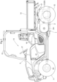
FIG. 1 is a side view of a utility vehicle; -
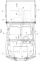
FIG. 2 is a plan view of the utility vehicle; -
FIG. 3 is a schematic diagram of an operation panel and therearound in a driver's section; -
FIG. 4 is a block diagram indicative of a configuration of a control of an electric work vehicle; -
FIG. 5 is a diagram indicative of a shift gate guiding a shift lever in a shift operation tool; -
FIG. 6 is a diagram indicative of the shift gate guiding the shift lever in the shift operation tool; -
FIG. 7 is a diagram indicative of the shift gate guiding the shift lever in the shift operation tool; and -
FIG. 8 is a diagram indicative of the shift gate guiding the shift lever in the shift operation tool. - Throughout embodiments, unless otherwise noted, "front" is defined as a front side corresponding to a front-back direction (traveling direction) relative to a body of the electric work vehicle, "back" is defined as a back side corresponding to the front-back direction relative to the body of the electric work vehicle, a left-right direction or a lateral direction is defined as a traversing direction (width direction) perpendicular to the front-back direction relative to the body of the electric work vehicle, "top" and "bottom" refer to positional relationship based on a ground height in a vertical direction relative to the body of the electric work vehicle.
- Modes for carrying out the present invention will be described with reference to the drawings showing a utility vehicle as an example of an electric work vehicle. An example of the utility vehicle shown in
FIGs. 1 and2 is utilizable for such multiple purposes as luggage-carrying, recreation, and the like. The electric work vehicle of the present invention includes an all-terrain vehicle (ATV), buggy, off-road vehicle, agricultural work vehicle, construction work vehicle, and the like. - The illustrated utility vehicle includes a pair of left and right drivable and steerable
front wheels 11 and a pair of left and right drivablerear wheels 12. Atravel body 1 is able to travel by the pair offront wheels 11 and the pair ofrear wheels 12. Thetravel body 1 includes a driver'ssection 13 in a center portion thereof which driver'ssection 13 an operator boards to perform an operation. Thetravel body 1 includes aloading platform 14 in a rear portion thereof on which luggage is loadable. Thetravel body 1 is mounted with amotive power unit 2 located in an area below theloading platform 14. Themotive power unit 2 includes a rotationally drivableelectric motor 2m as a chief element. - The
travel body 1 is mounted with apowertrain device 20. Thepowertrain device 20 transmits a motive power inputted from themotive power unit 2 to the pair offront wheels 11 and the pair ofrear wheels 12. In this way, the pair offront wheels 11 and the pair ofrear wheels 12 move on a ground based on a rotational drive of theelectric motor 2m. The pair offront wheels 11 and the pair ofrear wheels 12 correspond to a "travel device" recited in the claims. - The driver's
section 13 is surrounded and protected by aROPs frame 15 in a boxed shape. The driver'ssection 13 includes a driver'sseat 16 on which an operator sits. In front of the driver'sseat 16, the driver'ssection 13 includes afront panel 3 in which various operation tools and display devices are assembled, and asteering handle 17 for steering the pair offront wheels 11. The driver'ssection 13 includes anacceleration pedal 18 in a floor area thereof below thesteering handle 17. - The
powertrain device 20 to which the motive power from themotive power unit 2 is input includes agear transmission mechanism 21, a rearwheel differential mechanism 22, a frontwheel differential mechanism 23, and the like. Thegear transmission mechanism 21 in this embodiment includes atransmission 24. Thetransmission 24 is configured to switch a shift level between a high-speed stage and a low-speed stage by a high-low shift clutch. That is, thetransmission 24 is configured to transmit the motive power from theelectric motor 2m to the pair offront wheels 11 and the pair of rear wheels 12 (i.e., the travel device) while varying the speed of the rotation inputted from theelectric motor 2m. - To the
front panel 3, there are assembled: ameter panel 30 which has a liquid-crystal display (LCD) and light-emitting diode (LED) lamp; a singleshift operation part 31; a speedlimit operation tool 34; and the like. Theshift operation part 31 accepts a manual operation for changing the shift level of thetransmission 24. Theshift operation part 31 includes asingle shift lever 32, ashift gate 33. Theshift operation part 31 is provided with abiasing mechanism 32a. Alternatively, theshift operation part 31 may include thebiasing mechanism 32a. Theshift gate 33 is formed in a H-shape in thefront panel 3. Theshift lever 32 is movable along theshift gate 33 with the H-shape. Theshift lever 32 is operable in front, back, left and right directions. Thebiasing mechanism 32a biases theshift lever 32 to a neutral position described later. Thebiasing mechanism 32a may be a plate spring, a coil spring, a torsion spring or a rubber. Thebiasing mechanism 32a may also be a composite containing at least one of the spring and the rubber. Theshift operation part 31 corresponds to a "single operation tool" recited in claims. Theshift lever 32 corresponds to a "single lever" recited in claims. - The speed
limit operation tool 34 sets an upper limit of a vehicle speed. The speedlimit operation tool 34 is a circular dial tool. An arc-shaped upperspeed limit indicator 36 is provided around the speedlimit operation tool 34. The upperspeed limit indicator 36 has an arc-shaped scale indicative of the vehicle speed. The upperspeed limit indicator 36 is provided with apointer 37 which is disposed below the arc-shaped scale and mechanically linked to the speedlimit operation tool 34. - As shown in
FIG. 4 , a control configuration for theelectric motor 2m is provided with acontroller 40 and aninverter 41. Thecontroller 40 is a chief element of the electric work vehicle and is composed of a collection of multiple electronic control units (ECUs). Thecontroller 40 is configured to control the drive of theelectric motor 2m and the shift level of thetransmission 24. Thecontroller 40 connects with theshift lever 32 and theacceleration pedal 18. - A
travel battery device 42 is, for example, a lithium-ion battery. Not shown in diagrams, thetravel battery device 42 is composed of a plurality of small low-voltage unit batteries (cells) stacked together. Thetravel battery device 42 outputs a voltage of, for example, 250 volts. The unit batteries (cells) are housed in a sealed storage case of thetravel battery device 42. - The
controller 40 connects with theinverter 41 via a harness (not shown) for signals. Thecontroller 40 outputs a control signal to theinverter 41 in response to an operation of theacceleration pedal 18. In response to the control signal by thecontroller 40, theinverter 41 adjusts an electric power (voltage, frequency and current) to be supplied to theelectric motor 2m from thetravel battery device 42 and controls an output of theelectric motor 2m. - The
controller 40 connects with thetransmission 24 via a harness (not shown) for signals. Thecontroller 40 outputs a control signal to thetransmission 24 in response to an operation of theshift lever 32. Thetransmission 24 sets the shift level to either the high-speed stage or the low-speed stage in response to the control signal by thecontroller 40. - In this embodiment, the
shift lever 32 functions as a forward/reverse switching lever which switches a travel direction of the electric work vehicle between a forward travel and a reverse travel. Theshift gate 33 has aforward operation hole 33F for a forward operation, a reverse operation hole 33R for a reverse operation, and anintermediate hole 33M. Theforward operation hole 33F and the reverse operation hole 33R are arranged side by side, and configured to guide theshift lever 32 in the front-back direction during the operation of theshift lever 32. Theintermediate hole 33M is located between theforward operation hole 33F and the reverse operation hole 33R, and communicates with each of theforward operation hole 33F and the reverse operation hole 33R. - That is, the
intermediate hole 33M intersects with each of theforward operation hole 33F and the reverse operation hole 33R. Theintermediate hole 33M is configured to guide theshift lever 32 in the left-right direction during the operation of theshift lever 32. A right end portion (first end portion) of theintermediate hole 33M connects with theforward operation hole 33F. The reverse operation hole 33R intersects with a left end portion (second end portion), which is an opposite end portion of the right end portion, of theintermediate hole 33M and is configured to guide theshift lever 32 in the front-back direction during the operation of theshift lever 32. The forward operation hole 33F corresponds to a "first hole" recited in claims. Theintermediate hole 33M corresponds to a "second hole" recited in claims. The reverse operation hole 33R corresponds to a "third hole" recited in claims. - The both ends of the
forward operation hole 33F are respectively defined as a low-speedforward travel position 33a and a high-speedforward travel position 33b. The both ends of the reverse operation hole 33R are respectively defined as a low-speedreverse travel position 33c and a high-speedreverse travel position 33d. A middle position between the low-speedforward travel position 33a and the high-speedforward travel position 33b is aneutral position 33e. A middle position between the low-speedreverse travel position 33c and the high-speedreverse travel position 33d is aneutral position 33f. Bothneutral positions intermediate hole 33M. In other words, theintermediate hole 33M intersects with the longitudinal intermediate portion of theforward operation hole 33F and the longitudinal intermediate portion of the reverse operation hole 33R. - In this embodiment, as shown in
FIG. 4 theshift operation part 31 is provided with thebiasing mechanism 32a. Alternatively, theshift operation part 31 may include thebiasing mechanism 32a.FIGs. 5 to 8 shows a hatched line indicative of a biasing range BR in which an elasticity of thebiasing mechanism 32a affects on theshift lever 32. The area of the biasing range BR spans an area of theintermediate hole 33M and longitudinal intermediate areas of both theforward operation hole 33F and the reverse operation hole 33R. In a case that the operator does not operate theshift lever 32 and that theshift lever 32 is positioned within the biasing range BR, theshift lever 32 is returned to theneutral position 33e by the elasticity of thebiasing mechanism 32a. In other words, the position at which theforward operation hole 33F and theintermediate hole 33M intersect with each other is theneutral position 33e of theshift lever 32. When the operator operates theshift lever 32 from theneutral position 33e, the operation is against the elasticity of thebiasing mechanism 32a, to the low-speedforward travel position 33a, the high-speedforward travel position 33b, the low-speedreverse travel position 33c, or the high-speedreverse travel position 33d. - In a case of the
shift lever 32 positioned at theneutral position 33e or theneutral position 33f, thecontroller 40 prevents theelectric motor 2m from driving even when theacceleration pedal 18 is operated. In this case, theinverter 41 supplies no electric power to theelectric motor 2m. That is, thecontroller 40 is configured to transmit no motive power to the pair offront wheels 11 and the pair of rear wheels 12 (i.e., the travel device) in a case of theshift lever 32 positioned at theneutral positions - In a case of the
shift lever 32 positioned at the low-speedforward travel position 33a or the high-speedforward travel position 33b, thecontroller 40 outputs to theinverter 41 the control signal for a forward rotation of theelectric motor 2m, in response to the operation of theacceleration pedal 18. Theinverter 41 controls theelectric motor 2m to rotate theelectric motor 2m in a forward direction in response to the control signal by thecontroller 40. That is, thecontroller 40 is configured to control theelectric motor 2m to rotate in the direction which makes the pair offront wheels 11 and the pair of rear wheels 12 (i.e., the travel device) travel forward in a case of theshift lever 32 operated forward or backward along theforward operation hole 33F from theneutral position 33e. Thecontroller 40 controls theelectric motor 2m to rotate in the direction which makes the travel device travel forward in response to the operation of theacceleration pedal 18. Instead of theacceleration pedal 18, a tool for adjusting the speed of the rotation of theelectric motor 2m may be employed on the electric work vehicle. - In a case of the
shift lever 32 positioned at the low-speedreverse travel position 33c or the high-speedreverse travel position 33d, thecontroller 40 outputs to theinverter 41 the control signal for a reverse rotation of theelectric motor 2m, in response to the operation of theacceleration pedal 18. Theinverter 41 controls theelectric motor 2m to rotate theelectric motor 2m in a reverse direction in response to the control signal by thecontroller 40. Putting this configuration in other words, thecontroller 40 is configured to control theelectric motor 2m to rotate in the direction which makes the pair offront wheels 11 and the pair of rear wheels 12 (i.e., the travel device) travel backward in a case of theshift lever 32 operated leftward along theintermediate hole 33M (not along theforward operation hole 33F) from theneutral position 33e. Thecontroller 40 control theelectric motor 2m to rotate in the direction which makes the travel device travel backward in response to the operation of theacceleration pedal 18. - That is, the
controller 40 is configured to change the direction of the rotation of theelectric motor 2m in response to theshift lever 32 operated in the left-right direction and to change the shift level of thetransmission 24 in response to theshift lever 32 operated in the front-back direction. With this configuration in this embodiment, thepowertrain device 20 does not have to include a reverse mechanism for switching the travel direction between the forward travel and the reverse travel. In other words, switching of the direction of the rotation of theelectric motor 2m realizes switching between the forward travel and the reverse travel. In this way, theshift lever 32 is configured to accept the manual operation for changing the direction of the rotation of theelectric motor 2m and for changing the shift level of thetransmission 24. Thecontroller 40 is configured to output the control signal to theelectric motor 2m and thetransmission 24 based on the manual operation accepted by theshift lever 32. - With the above-described configuration in this embodiment, it is possible to switch the direction of the rotation of the
electric motor 2m and to change the shift level of thetransmission 24 by the singleshift operation part 31, i.e., by thesingle shift lever 32. - The present invention is not limited to the configuration illustrated in the above embodiment. Other representative embodiments of the invention will be described below.
- (1) The reverse operation hole 33R shown in
FIG.5 is positioned on the left side of theforward operation hole 33F. Alternatively, the reverse operation hole 33R may be positioned on the right side of theforward operation hole 33F. That is, thecontroller 40 may be configured to control theelectric motor 2m to rotate in the direction which makes the pair offront wheels 11 and the pair of rear wheels 12 (i.e., the travel device) travel backward in a case of theshift lever 32 operated on the left or right side of theneutral position 33e (not along theforward operation hole 33F). - (2) The electric work vehicle may include a
shift gate 51 shown inFIG. 6 instead of theshift gate 33 shown inFIG. 5 . InFIG. 6 as an example, aforward operation hole 51F (first hole) and areverse operation hole 51R (third hole) each extend in the front-back direction. Front and back end portions of theforward operation hole 51F are respectively defined as a low-speedforward travel position 51a and a high-speedforward travel position 51b. Front and back end portions of thereverse operation hole 51R are respectively defined as a low-speedreverse travel position 51c and a high-speedreverse travel position 51d. The low-speedreverse travel position 51c is positioned in an upside of the high-speedreverse travel position 51d from the paper perspective inFIG.6 . A middle position between the low-speedforward travel position 51a and the high-speedforward travel position 51b is aneutral position 51e. Anintermediate hole 51M (second hole) is located between theneutral position 51e and the low-speedreverse travel position 51c, and communicates with each of theforward operation hole 51F and thereverse operation hole 51R. Predetermined upper and lower areas relative to theneutral position 51e in theforward operation hole 51F and a predetermined area to left of theneutral position 51e in theintermediate hole 51M form a biasing range BR of thebiasing mechanism 32a. Although thereverse operation hole 51R is positioned on a left side of theforward operation hole 51F, thereverse operation hole 51R may be positioned on a right side of the forward operation hole S1F. - (3) The electric work vehicle may include a
shift gate 52 shown inFIG. 7 instead of theshift gate 33 shown inFIG. 5 . InFIG. 7 as an example, aforward operation hole 52F (first hole) extends in the front-back direction and areverse operation hole 52R (second hole) extends in the left-right direction. Theforward operation hole 52F and thereverse operation hole 52R intersect with each other in a cross shape. Front and back end portions of theforward operation hole 52F are respectively defined as a low-speedforward travel position 52a and a high-speedforward travel position 52b. Left and right end portions of thereverse operation hole 51R are respectively defined as a low-speedreverse travel position 52c and a high-speedreverse travel position 52d. A middle position between the low-speedforward travel position 52a and the high-speedforward travel position 52b and between the low-speedreverse travel position 52c and the high-speedreverse travel position 52d is a position where theforward operation hole 52F and thereverse operation hole 52R intersects with each other in the cross shape, i.e., aneutral position 52e. Predetermined upper and lower areas relative to theneutral position 52e in theforward operation hole 52F and predetermined left and right areas relative to theneutral position 52e in thereverse operation hole 52R form a biasing range BR of thebiasing mechanism 32a. - (4) The electric work vehicle may include a
shift gate 53 shown inFIG. 8 instead of theshift gate 33 shown inFIG. 5 . InFIG. 8 as an example, aforward operation hole 53F (first hole) and areverse operation hole 53R (third hole) each extend in the front-back direction. Back and front end portions of theforward operation hole 53F are respectively defined as a low-speedforward travel position 53a and a high-speedforward travel position 53b. The low-speedforward travel position 53a is positioned on a downside of the high-speedforward travel position 53b from the paper perspective inFIG.8 . Front and back end portions of thereverse operation hole 53R are respectively defined as a low-speedreverse travel position 53c and a high-speedreverse travel position 53d. The low-speedreverse travel position 53c is positioned on an upside of the high-speedreverse travel position 53d from the paper perspective inFIG.8 . Anintermediate hole 53M (second hole), extending in the left-right direction, is located between the low-speedforward travel position 53a and the low-speedreverse travel position 53c, and communicates with each of theforward operation hole 53F and thereverse operation hole 53R. Aneutral position 53e is located at an intermediate area of theintermediate hole 53M in the left-right direction. Predetermined left and right areas relative to theneutral position 53e in theintermediate hole 53M form a biasing range BR of thebiasing mechanism 32a. Although thereverse operation hole 53R is positioned on a left side of theforward operation hole 53F, thereverse operation hole 53R may be positioned on a right side of theforward operation hole 53F. - Note that the configuration disclosed in the above embodiments (including other embodiments; the same applies to the following) may be combined with configurations disclosed in other embodiments, as long as no contradiction arises. The embodiments disclosed herein are illustrative. Embodiments of the present invention are not limited thereto, and can be altered without departing from the object of the present invention.
- The present invention is applicable to an electric work vehicle.
Claims (8)
- An electric work vehicle comprising:a rotationally drivable electric motor (2m);a travel device (11, 12) configured to travel on a ground based on a drive of the electric motor (2m);a transmission (24) configured to transmit a motive power from the electric motor (2m) to the travel device (11, 12) while varying a speed of a rotation inputted from the electric motor (2m);a single operation part (31) configured to accept a manual operation for changing a direction of the rotation of the electric motor (2m) and for changing a shift level of the transmission (24); anda controller (40) configured to output a control signal to the electric motor (2m) and the transmission (24) based on the manual operation accepted by the single operation part (31).
- The electric work vehicle according to claim 1, whereinthe single operation part (31) includes a single lever (32) movable in front, back, left and right directions, andthe controller (40) is configured to change the direction of the rotation of the electric motor (2m) in response to the single lever (32) operated in a left-right direction and to change the shift level of the transmission (24) in response to the single lever (32) operated in a front-back direction.
- The electric work vehicle according to claim 2, whereinthe single operation part (31) includes:a first hole (33F, 51F, 52F, 53F) configured to guide the single lever (32) in the front-back direction during the manual operation of the single lever (32); anda second hole (33M, 51M, 52R, 53M) configured to guide the single lever (32) in the left-right direction during the manual operation of the single lever (32), andthe first hole (33F, 51F, 52F, 53F) and the second hole (33M, 51M, 52R, 53M) intersect with each other.
- The electric work vehicle according to claim 3, whereinthe first hole (33F, 51F, 52F, 53F) and the second hole (33M, 51M, 52R, 53M) intersect with each other at a neutral position (33e, 51e, 52e) of the single lever (32), andthe controller (40) is configured to:transmit no motive power to the travel device (11, 12) in a case of the single lever (32) positioned at the neutral position (33e, 51e, 52e, 53e);control the electric motor (2m) to rotate in the direction which moves the travel device (11, 12) forward in a case of the single lever (32) operated forward or backward along the first hole (33F, S1F, 52F, 53F) from the neutral position (33e, 51e, 52e); andcontrol the electric motor (2m) to rotate in the direction which moves the travel device (11, 12) backward in a case of the single lever (32) operated leftward or rightward not along the first hole (33F, S1F, 52F, 53F) from the neutral position (33e, 51e, 52e).
- The electric work vehicle according to claim 4, wherein
the single operation part (31) is provided with a biasing mechanism which biases the single lever (32) to the neutral position (33e, 51e, 52e, 53e). - The electric work vehicle according to claim 3 or 4, wherein
the second hole (33M, 51M, 52R, 53M) intersects with a longitudinal intermediate portion of the first hole (33F, 51F, 52F, 53F) in the front-back direction. - The electric work vehicle according to claim 3 or 4, wherein
the second hole (33M, 51M, 52R, 53M) intersects with the first hole (33F, 51F, 52F, 53F) with a first end portion thereof. - The electric work vehicle according to claim 7, wherein
the single operation part (31) includes a third hole (33R) which intersects with a second end portion of the second hole (33M, 51M, 52R, 53M), and configured to guide the single lever (32) in the front-back direction during the manual operation of the single lever (32), the second end portion being an opposite end of the first end portion.
Applications Claiming Priority (1)
| Application Number | Priority Date | Filing Date | Title |
|---|---|---|---|
| JP2022181172A JP2024070583A (en) | 2022-11-11 | 2022-11-11 | Electric work vehicle |
Publications (2)
| Publication Number | Publication Date |
|---|---|
| EP4368858A1 true EP4368858A1 (en) | 2024-05-15 |
| EP4368858B1 EP4368858B1 (en) | 2026-03-25 |
Family
ID=88237409
Family Applications (1)
| Application Number | Title | Priority Date | Filing Date |
|---|---|---|---|
| EP23201104.9A Active EP4368858B1 (en) | 2022-11-11 | 2023-10-02 | Electric work vehicle |
Country Status (3)
| Country | Link |
|---|---|
| US (1) | US20240157813A1 (en) |
| EP (1) | EP4368858B1 (en) |
| JP (1) | JP2024070583A (en) |
Citations (6)
| Publication number | Priority date | Publication date | Assignee | Title |
|---|---|---|---|---|
| US20050230158A1 (en) * | 2004-02-04 | 2005-10-20 | Honda Motor Co., Ltd. | Electric vehicle |
| US20150266376A1 (en) * | 2014-03-24 | 2015-09-24 | Mazda Motor Corporation | Shift control device for vehicle |
| US20170158044A1 (en) * | 2015-12-07 | 2017-06-08 | Kubota Corporation | Utility Vehicle |
| JP2019060426A (en) | 2017-09-27 | 2019-04-18 | 株式会社クボタ | Work vehicle |
| US20200101972A1 (en) * | 2018-10-01 | 2020-04-02 | Hyundai Motor Company | Driving system for electric vehicle and control method thereof |
| US20200348714A1 (en) * | 2019-05-02 | 2020-11-05 | Deere & Company | Variable track joystick devices and work vehicles containing the same |
Family Cites Families (9)
| Publication number | Priority date | Publication date | Assignee | Title |
|---|---|---|---|---|
| JPH11165551A (en) * | 1997-12-04 | 1999-06-22 | Iseki & Co Ltd | Work vehicle shift structure |
| CA2409913C (en) * | 2001-11-06 | 2011-02-15 | Honda Giken Kogyo Kabushiki Kaisha | Electric vehicle |
| US7648001B2 (en) * | 2005-09-13 | 2010-01-19 | Kubota Corporation | Speed shift arrangement for work vehicle |
| JP2007137323A (en) * | 2005-11-21 | 2007-06-07 | Yanmar Co Ltd | Working vehicle |
| EP2694310A2 (en) * | 2011-04-08 | 2014-02-12 | Polaris Industries Inc. | Electric vehicle with range extender |
| JP6338876B2 (en) * | 2014-02-10 | 2018-06-06 | 本田技研工業株式会社 | Power transmission device for electric equipment |
| JP6371239B2 (en) * | 2015-02-27 | 2018-08-08 | 株式会社日立建機カミーノ | Hand guide roller |
| JP7050421B2 (en) * | 2017-03-27 | 2022-04-08 | 株式会社クボタ | Multipurpose vehicle |
| JP2018165075A (en) * | 2017-03-28 | 2018-10-25 | 三菱マヒンドラ農機株式会社 | Work vehicle |
-
2022
- 2022-11-11 JP JP2022181172A patent/JP2024070583A/en active Pending
-
2023
- 2023-09-27 US US18/373,574 patent/US20240157813A1/en active Pending
- 2023-10-02 EP EP23201104.9A patent/EP4368858B1/en active Active
Patent Citations (6)
| Publication number | Priority date | Publication date | Assignee | Title |
|---|---|---|---|---|
| US20050230158A1 (en) * | 2004-02-04 | 2005-10-20 | Honda Motor Co., Ltd. | Electric vehicle |
| US20150266376A1 (en) * | 2014-03-24 | 2015-09-24 | Mazda Motor Corporation | Shift control device for vehicle |
| US20170158044A1 (en) * | 2015-12-07 | 2017-06-08 | Kubota Corporation | Utility Vehicle |
| JP2019060426A (en) | 2017-09-27 | 2019-04-18 | 株式会社クボタ | Work vehicle |
| US20200101972A1 (en) * | 2018-10-01 | 2020-04-02 | Hyundai Motor Company | Driving system for electric vehicle and control method thereof |
| US20200348714A1 (en) * | 2019-05-02 | 2020-11-05 | Deere & Company | Variable track joystick devices and work vehicles containing the same |
Also Published As
| Publication number | Publication date |
|---|---|
| US20240157813A1 (en) | 2024-05-16 |
| EP4368858B1 (en) | 2026-03-25 |
| JP2024070583A (en) | 2024-05-23 |
Similar Documents
| Publication | Publication Date | Title |
|---|---|---|
| JP2005193788A (en) | Electric power steering device for snow vehicles | |
| JP6494498B2 (en) | Multipurpose vehicle | |
| JP6827364B2 (en) | Multipurpose vehicle | |
| EP4368858B1 (en) | Electric work vehicle | |
| EP3884758B1 (en) | Work vehicle | |
| JP5958363B2 (en) | Traveling vehicle | |
| JP7046736B2 (en) | Work vehicle | |
| JP7046737B2 (en) | Work vehicle | |
| JP4161912B2 (en) | Seedling transplanter | |
| CN110654233A (en) | Working vehicle | |
| JP6735698B2 (en) | Work vehicle | |
| JP2009166685A (en) | Power steering control device | |
| JP7059123B2 (en) | Work vehicle | |
| JP2013112233A (en) | Work vehicle | |
| KR101315149B1 (en) | Electric Multi-purpose Utility vehicle | |
| EP4015277A1 (en) | Work vehicle, control method, control program and recording medium | |
| JP2007321987A (en) | Powered vehicle | |
| JP7788986B2 (en) | Utility Vehicle | |
| JP4537918B2 (en) | Tractor shifting operation device | |
| US20240359555A1 (en) | Electric Motor Power Train and Utility Vehicle | |
| JP7482766B2 (en) | Work vehicle | |
| US12600251B2 (en) | Electric work vehicle | |
| EP3718808B1 (en) | Operation mechanism of work vehicle and work vehicle | |
| US20250289355A1 (en) | Work Vehicle | |
| JP2905080B2 (en) | Combine transmission structure |
Legal Events
| Date | Code | Title | Description |
|---|---|---|---|
| PUAI | Public reference made under article 153(3) epc to a published international application that has entered the european phase |
Free format text: ORIGINAL CODE: 0009012 |
|
| STAA | Information on the status of an ep patent application or granted ep patent |
Free format text: STATUS: REQUEST FOR EXAMINATION WAS MADE |
|
| 17P | Request for examination filed |
Effective date: 20231002 |
|
| AK | Designated contracting states |
Kind code of ref document: A1 Designated state(s): AL AT BE BG CH CY CZ DE DK EE ES FI FR GB GR HR HU IE IS IT LI LT LU LV MC ME MK MT NL NO PL PT RO RS SE SI SK SM TR |
|
| RIC1 | Information provided on ipc code assigned before grant |
Ipc: F16H 59/10 20060101AFI20250827BHEP Ipc: F16H 63/50 20060101ALI20250827BHEP Ipc: B60K 20/02 20060101ALI20250827BHEP |
|
| GRAP | Despatch of communication of intention to grant a patent |
Free format text: ORIGINAL CODE: EPIDOSNIGR1 |
|
| STAA | Information on the status of an ep patent application or granted ep patent |
Free format text: STATUS: GRANT OF PATENT IS INTENDED |
|
| INTG | Intention to grant announced |
Effective date: 20251013 |
|
| GRAS | Grant fee paid |
Free format text: ORIGINAL CODE: EPIDOSNIGR3 |
|
| GRAA | (expected) grant |
Free format text: ORIGINAL CODE: 0009210 |
|
| STAA | Information on the status of an ep patent application or granted ep patent |
Free format text: STATUS: THE PATENT HAS BEEN GRANTED |
|
| P01 | Opt-out of the competence of the unified patent court (upc) registered |
Free format text: CASE NUMBER: UPC_APP_0004416_4368858/2026 Effective date: 20260209 |
|
| AK | Designated contracting states |
Kind code of ref document: B1 Designated state(s): AL AT BE BG CH CY CZ DE DK EE ES FI FR GB GR HR HU IE IS IT LI LT LU LV MC ME MK MT NL NO PL PT RO RS SE SI SK SM TR |
|
| REG | Reference to a national code |
Ref country code: CH Ref legal event code: F10 Free format text: ST27 STATUS EVENT CODE: U-0-0-F10-F00 (AS PROVIDED BY THE NATIONAL OFFICE) Effective date: 20260325 Ref country code: GB Ref legal event code: FG4D |
|
| REG | Reference to a national code |
Ref country code: DE Ref legal event code: R096 Ref document number: 602023013995 Country of ref document: DE |
|
| REG | Reference to a national code |
Ref country code: IE Ref legal event code: FG4D |