EP4368515B1 - Aéronef muni d'un conduit d'échappement couplé à un système de stabilisation - Google Patents
Aéronef muni d'un conduit d'échappement couplé à un système de stabilisation Download PDFInfo
- Publication number
- EP4368515B1 EP4368515B1 EP23200550.4A EP23200550A EP4368515B1 EP 4368515 B1 EP4368515 B1 EP 4368515B1 EP 23200550 A EP23200550 A EP 23200550A EP 4368515 B1 EP4368515 B1 EP 4368515B1
- Authority
- EP
- European Patent Office
- Prior art keywords
- exhaust duct
- aircraft
- stiffening ring
- aircraft according
- cowl
- Prior art date
- Legal status (The legal status is an assumption and is not a legal conclusion. Google has not performed a legal analysis and makes no representation as to the accuracy of the status listed.)
- Active
Links
Images
Classifications
-
- B—PERFORMING OPERATIONS; TRANSPORTING
- B64—AIRCRAFT; AVIATION; COSMONAUTICS
- B64D—EQUIPMENT FOR FITTING IN OR TO AIRCRAFT; FLIGHT SUITS; PARACHUTES; ARRANGEMENT OR MOUNTING OF POWER PLANTS OR PROPULSION TRANSMISSIONS IN AIRCRAFT
- B64D33/00—Arrangement in aircraft of power plant parts or auxiliaries not otherwise provided for
- B64D33/04—Arrangement in aircraft of power plant parts or auxiliaries not otherwise provided for of exhaust outlets or jet pipes
-
- B—PERFORMING OPERATIONS; TRANSPORTING
- B64—AIRCRAFT; AVIATION; COSMONAUTICS
- B64D—EQUIPMENT FOR FITTING IN OR TO AIRCRAFT; FLIGHT SUITS; PARACHUTES; ARRANGEMENT OR MOUNTING OF POWER PLANTS OR PROPULSION TRANSMISSIONS IN AIRCRAFT
- B64D33/00—Arrangement in aircraft of power plant parts or auxiliaries not otherwise provided for
- B64D33/02—Arrangement in aircraft of power plant parts or auxiliaries not otherwise provided for of combustion air intakes
-
- B—PERFORMING OPERATIONS; TRANSPORTING
- B64—AIRCRAFT; AVIATION; COSMONAUTICS
- B64C—AEROPLANES; HELICOPTERS
- B64C27/00—Rotorcraft; Rotors peculiar thereto
- B64C27/04—Helicopters
-
- F—MECHANICAL ENGINEERING; LIGHTING; HEATING; WEAPONS; BLASTING
- F01—MACHINES OR ENGINES IN GENERAL; ENGINE PLANTS IN GENERAL; STEAM ENGINES
- F01D—NON-POSITIVE DISPLACEMENT MACHINES OR ENGINES, e.g. STEAM TURBINES
- F01D25/00—Component parts, details, or accessories, not provided for in, or of interest apart from, other groups
- F01D25/30—Exhaust heads, chambers, or the like
-
- F—MECHANICAL ENGINEERING; LIGHTING; HEATING; WEAPONS; BLASTING
- F02—COMBUSTION ENGINES; HOT-GAS OR COMBUSTION-PRODUCT ENGINE PLANTS
- F02K—JET-PROPULSION PLANTS
- F02K1/00—Plants characterised by the form or arrangement of the jet pipe or nozzle; Jet pipes or nozzles peculiar thereto
- F02K1/04—Mounting of an exhaust cone in the jet pipe
-
- F—MECHANICAL ENGINEERING; LIGHTING; HEATING; WEAPONS; BLASTING
- F02—COMBUSTION ENGINES; HOT-GAS OR COMBUSTION-PRODUCT ENGINE PLANTS
- F02K—JET-PROPULSION PLANTS
- F02K1/00—Plants characterised by the form or arrangement of the jet pipe or nozzle; Jet pipes or nozzles peculiar thereto
- F02K1/78—Other construction of jet pipes
- F02K1/80—Couplings or connections
-
- B—PERFORMING OPERATIONS; TRANSPORTING
- B64—AIRCRAFT; AVIATION; COSMONAUTICS
- B64D—EQUIPMENT FOR FITTING IN OR TO AIRCRAFT; FLIGHT SUITS; PARACHUTES; ARRANGEMENT OR MOUNTING OF POWER PLANTS OR PROPULSION TRANSMISSIONS IN AIRCRAFT
- B64D29/00—Power-plant nacelles, fairings or cowlings
- B64D29/08—Inspection panels for power plants
-
- F—MECHANICAL ENGINEERING; LIGHTING; HEATING; WEAPONS; BLASTING
- F05—INDEXING SCHEMES RELATING TO ENGINES OR PUMPS IN VARIOUS SUBCLASSES OF CLASSES F01-F04
- F05D—INDEXING SCHEME FOR ASPECTS RELATING TO NON-POSITIVE-DISPLACEMENT MACHINES OR ENGINES, GAS-TURBINES OR JET-PROPULSION PLANTS
- F05D2220/00—Application
- F05D2220/30—Application in turbines
- F05D2220/32—Application in turbines in gas turbines
- F05D2220/329—Application in turbines in gas turbines in helicopters
-
- F—MECHANICAL ENGINEERING; LIGHTING; HEATING; WEAPONS; BLASTING
- F05—INDEXING SCHEMES RELATING TO ENGINES OR PUMPS IN VARIOUS SUBCLASSES OF CLASSES F01-F04
- F05D—INDEXING SCHEME FOR ASPECTS RELATING TO NON-POSITIVE-DISPLACEMENT MACHINES OR ENGINES, GAS-TURBINES OR JET-PROPULSION PLANTS
- F05D2230/00—Manufacture
- F05D2230/60—Assembly methods
- F05D2230/64—Assembly methods using positioning or alignment devices for aligning or centring, e.g. pins
- F05D2230/642—Assembly methods using positioning or alignment devices for aligning or centring, e.g. pins using maintaining alignment while permitting differential dilatation
-
- F—MECHANICAL ENGINEERING; LIGHTING; HEATING; WEAPONS; BLASTING
- F05—INDEXING SCHEMES RELATING TO ENGINES OR PUMPS IN VARIOUS SUBCLASSES OF CLASSES F01-F04
- F05D—INDEXING SCHEME FOR ASPECTS RELATING TO NON-POSITIVE-DISPLACEMENT MACHINES OR ENGINES, GAS-TURBINES OR JET-PROPULSION PLANTS
- F05D2260/00—Function
- F05D2260/96—Preventing, counteracting or reducing vibration or noise
Definitions
- the present invention relates to an aircraft having an exhaust duct coupled to a stabilization system which is configured to stabilize the exhaust duct.
- An aircraft such as a rotorcraft, may include an engine that expels combustion gases through an exhaust nozzle.
- the engine is usually housed in a compartment of the aircraft called the "engine compartment".
- the engine compartment may be delimited by one or more firewalls and/or at least one cowl.
- the aircraft may then comprise an exhaust duct which is open to the engine compartment and to an environment external to the aircraft.
- the exhaust duct may be fixed and arranged in a housing delimited by a movable cowl, or even a firewall for example.
- This exhaust duct locally surrounds the exhaust nozzle.
- This exhaust duct may allow the combustion gases from the exhaust nozzle of an engine to be mixed with fresh air from the engine compartment and/or the gases to be directed to preferential zones.
- the exhaust nozzle may be described as a primary or main nozzle, the exhaust duct being able to be described as a secondary nozzle.
- the rotation of a helicopter main rotor, the operation of an engine, and a structure supporting the exhaust duct are sources of vibration that can excite an exhaust duct.
- the movement of air near the exhaust pipe is also a source of vibrations for this exhaust pipe.
- an exhaust duct is likely to deform in flight due to these various constraints, in particular due to thermal constraints as well as its vibratory and dynamic behavior and the setting of its natural frequency with respect to the frequencies of the excitations undergone.
- Modifying the exhaust pipe to limit these deformations can be relatively tricky, in terms of financial cost, time, and even mass.
- modifying an exhaust pipe can have an impact on its environment, and for example on the supporting structure that must support the exhaust pipe.
- the document EP3575219 describes a rotorcraft having at least one engine associated with an exhaust duct.
- the exhaust duct is attached to a fixed structure of the rotorcraft by a mechanism to be stabilized statically as well as following thermal expansion.
- the document EP2894099 describes a method of manufacturing an exhaust duct provided with fixing rings.
- the document WO2009/083074A1 describes a device for cooling a hot gas to be exhausted from an aircraft, which device includes a channel adapted to conduct the hot gas from a hot gas source connectable to the device to an outlet point, and a frame that surrounds the channel and is adapted to hold the channel.
- the channel is formed from one or more tube sections and has one or more cooling air inlet points that are connectable to one or more cooling air sources to mix the hot gas with cooling air.
- the documents WO 99/54204 A1 And US 2,653,585 A are also known.
- the present invention aims to propose an aircraft according to claim 1 which is equipped with an exhaust duct cooperating with an innovative stabilization system.
- the invention relates to an aircraft equipped with at least one duct exhaust for ejecting gases from an engine, the exhaust duct being partially housed in a housing internal of the aircraft, the housing being separated from an external environment located outside the aircraft by at least one cover, this cover being movable relative to a supporting structure of the aircraft, the exhaust duct comprising an ejector section passing through a passage of the cover without touching the cover, a space separating the ejector section from the cover.
- This aircraft comprises according to this claim 1 at least one stabilization system coupled to the exhaust duct, the stabilization system comprising a stiffening ring secured to the exhaust duct and at least one fastener connecting the exhaust duct to the cowl.
- the stabilization system comprises two dissimilar devices which operate in synergy to improve, in use, the behavior of the exhaust duct with regard to the stresses undergone.
- Optional features of this aircraft are described in dependent claims 2-13.
- a stiffening ring is positioned around the exhaust duct, and against this exhaust duct.
- the stiffening ring makes it possible to modify the natural frequency of the exhaust duct to move it away from an excitation frequency.
- the stiffening ring also makes it possible to locally constrain the exhaust duct to prevent its deformation, for example by avoiding ovalization of the exhaust duct.
- This stiffening ring can be arranged so as to have an acceptable impact on the aerodynamics of the aircraft, or even on the ventilation of the housing.
- the fastener(s) enable the exhaust duct to be secured to the cowling in order to stabilize the exhaust duct in flight.
- the fastener(s) may be defined so as not to hinder the thermal expansion of the exhaust duct in operation while constraining its movement in the aircraft reference frame.
- the fastener(s) may further be defined so as to allow a quick detachment of the exhaust pipe and the hood, and thus to allow the hood to be opened.
- This stabilization system can have a low mass impact, has no impact on the exhaust duct environment except for the cowling and can be installed on an existing aircraft during a so-called "retrofit" campaign in English.
- the aircraft may further include one or more of the following features, taken alone or in combination.
- the stiffening ring can surround the exhaust duct.
- the stiffening ring can surround a section of the exhaust duct, namely completely and therefore 360 degrees around an internal volume of the exhaust duct.
- the stiffening ring may extend over an angle of less than 360 degrees around a geometric axis, and thus the internal volume. The stiffening ring then only partially surrounds the exhaust duct.
- the stiffening ring can be arranged around the ejector section.
- the stiffening ring generates pressure on the exhaust duct when the exhaust duct expands under the effect of the gas temperature.
- the pressure generated by the stiffening ring on the exhaust duct can be optimized when the stiffening ring is arranged on the ejector section which is likely to undergo less thermal expansion than an inlet section of the exhaust duct for example.
- the stiffening ring tends to stiffen the ejector section which is likely to deform within a standard exhaust duct.
- the stiffening ring can be arranged at least partially in the external environment.
- the impact on the aerodynamics of the aircraft is thus limited.
- the stiffening ring remains arranged as close as possible, or even on the section of the exhaust duct which is likely to deform within a conventional exhaust duct.
- the stiffening ring can be arranged entirely in the external environment.
- the stiffening ring can comprise an L-shaped, T-shaped, C-shaped or omega-shaped profile.
- the omega shape can comprise a substantially flat branch, followed by a substantially rounded or non-rounded C-shaped branch tilted 90 degrees to the right, then another substantially flat branch.
- Such a profile may be sufficient to adequately modify the behavior of the exhaust duct.
- the stiffening ring can be fixed to the exhaust duct by detachable stiffening fasteners.
- dissociable refers to fasteners that can be removed without damaging the stiffener ring and/or the exhaust duct during a maintenance campaign.
- stiffening fasteners include rivets or the like.
- said at least one fixing may comprise a first support secured to the exhaust duct and a second support secured to the hood, said at least one fixing comprising a connecting clip fixing the first support to the second support.
- the connecting clip may be a so-called quick-release clip.
- the connecting clip may include a quarter-turn clip or even a fastener known under the brand name dzus ® for example. An operator can then easily separate the exhaust duct and the hood.
- said at least one fixing can be arranged at least partially in said housing.
- the fastener may be entirely housed within the housing or may extend outside the housing.
- the aforementioned fastener may be located in the external environment.
- said at least one fixing can be accessible via said space separating the ejector section from the hood.
- the space may have dimensions greater than the dimensions of a human hand or a tool capable of opening the fastener.
- the space may have a dimension of at least 5 centimeters.
- the arrangement of the exhaust duct in a larger hood passage allows for a space that can be passed through by a tool and/or a hand. An operator can insert a hand into the space to detach the hood exhaust pipe, in order to open the hood for example.
- said at least one fixing can be adjacent to the stiffening ring.
- the fastener(s) are as close as possible to the stiffening ring to provide fixing points and stiffness in roughly the same location.
- At least one fastener may be attached to the stiffening ring.
- the fastener thus connects the exhaust duct to the hood via the stiffening ring.
- the bracket can be attached directly to the exhaust duct.
- said at least one fixing may comprise several fixings arranged around the exhaust duct.
- the fasteners are then distributed, in an iso-distributed or non-iso-distributed manner, around the exhaust duct to stabilize the exhaust duct in several zones and along several geometric axes.
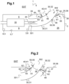
- FIG. 1 presents an aircraft 1 according to the invention.
- Such an aircraft 1 comprises a supporting structure 3 carrying at least one engine 10.
- the engine 10 is in particular arranged in an engine compartment 5.
- the engine compartment 5 is delimited by at least one wall 6, 7, 8 and 9.
- the wall(s) 6, 7, 8 and 9 may be fireproof walls, for example fireproof.
- the engine compartment 5 is delimited along a longitudinal axis by at least one longitudinal wall 6, 8.
- the engine compartment 5 is delimited along a transverse axis by at least one transverse wall 7 and a cowling, and vertically at least by a bottom wall 9.
- the engine(s) 10 may be heat engines capable of burning fuel to drive each power shaft. According to one possibility, the engine(s) 10 may be turboshaft engines. Alternatively, the engine(s) 10 may be piston engines for example.
- each engine 10 comprises an ejection nozzle 20 for at least ejecting, along the arrow F1, gases resulting from the combustion of the fuel in the engine 10 in question.
- the ejection nozzle 20 passes through a longitudinal wall 6.
- an exhaust duct 30 at least partially surrounds the ejection nozzle 20, namely the entire ejection nozzle 20 or a section of the ejection nozzle 20 and for example at least one ejection portion of the ejection nozzle 20 through which gases are expelled.
- the exhaust duct 30 surrounds at least a portion of the ejection nozzle 20 located outside the engine compartment 5.
- the exhaust duct 30 may comprise a peripheral wall.
- the peripheral wall delimits an internal volume located inside the exhaust duct 30 and accommodating at least one section of the ejection nozzle 20.
- the exhaust duct 30 extends from an inlet section 301, possibly opening onto the engine compartment 5, to an outlet section 302, possibly opening onto an environment EXT located outside the aircraft 1. Consequently, air present in the compartment 5 can be sucked into the exhaust duct 30, then is expelled outside the vehicle with gases coming from the ejection nozzle 20 via the outlet section 302.
- the exhaust duct may comprise an inlet section 31 comprising the inlet section 301, then an ejector section 32 comprising the outlet section 302.
- exhaust duct 30 is partially housed in an internal housing 25 of the aircraft 1.
- the inlet section of the conduit can be fixed to a wall delimiting the housing, and for example the wall 8.
- the exhaust duct 30 can be stationary in the reference frame of the aircraft and in the housing 25.
- This housing 25 is in particular separated from the external environment EXT at least by a cover 35.
- the cover 35 is movable relative to the supporting structure 3 of the aircraft 1, and to the exhaust duct.
- the cover 35 can be connected to the supporting structure 3 by at least one mobility system 38, 39 illustrated schematically.
- a mobility system 38, 39 can comprise at least one rail, at least one slider, at least one hinge for example.
- the hood 35 may include a cowling panel 36.
- the hood 35 may include a protective casing 37 secured to the cowling panel 36 as illustrated in FIG. figure 2 described below.
- the hood 35 Independently of the components of the hood 35 and of the mobility systems 38, 39 making it mobile relative to the supporting structure 3, the hood 35 comprises a passage 40.
- a passage 40 may comprise a cutout made in the hood panel 36, and where appropriate not blocked by the protective casing 37.
- the ejector section 32 of the exhaust duct 30 passes through the passage 40 of the cover 35 without touching this cover 35.
- the ejector section can thus extend into the external environment EXT.
- a space 41 therefore separates the ejector section 32 from the cover 35.
- This space 41 is an annular space which surrounds the exhaust duct by separating it from an edge delimiting the passage 40.
- the aircraft 1 comprises at least one stabilization system 50 coupled to an exhaust duct 30.
- each exhaust pipe 30 is coupled to its own stabilization system 50.
- such a stabilization system 50 makes it possible to modify the dynamic and vibrational behavior of the exhaust duct 30, without constraint on the supporting structure 3 or the engine compartment 5 for example.
- Such a stabilization system 50 comprises a stiffening ring 55 which is attached to the exhaust duct 30.
- the stiffening ring can completely surround the exhaust duct, namely 360 degrees around a geometric axis, or can partially surround the exhaust duct.
- This stiffening ring 55 is thus made integral with the exhaust duct 30.
- stiffening ring 55 is arranged against the ejector section 32.
- the stiffening ring 55 can be arranged at least partially in the external environment EXT.
- the stiffening ring 55 and the exhaust duct 30 form a single piece, the stiffening ring 55 and the exhaust duct 30 being inseparable without breakage.
- the stiffening ring 55 is welded to the exhaust duct 30.
- the stiffening ring 55 is fixed to the exhaust duct 30 by detachable stiffening fasteners 56.
- the stiffening fasteners 56 comprise rivets.
- the stiffening ring 55 can have an L-shaped, T-shaped, C-shaped or omega-shaped profile. Such a stiffening ring 55 makes it possible to modify the natural frequency of the exhaust duct 30 relatively easily and at low cost.
- the stabilization system 50 also comprises one or more fasteners 60 connecting the exhaust duct 30 to the cover 35. At least one fastener 60 may in particular be fixed to the ejector section 32. According to the examples illustrated, the stabilization system 50 comprises several fasteners 60 arranged around the exhaust duct 30.
- At least one fastener 60 can in particular be fixed to the cover panel 36 of the hood 35.
- At least one fastener 60 can in particular be fixed to the protective casing 37 of the cover 35.
- At least one fastener 60 is optionally positioned so as to be adjacent to the stiffening ring 55.
- At least one fastener 60 may be attached to the stiffening ring 55.
- this fixing 60 may comprise a first support 61 and a second support 62 assembled to each other by a connecting clip 63.
- the first support 61 is integral with the exhaust duct 30, directly or via the stiffening ring 55.
- the first support 61 can be fixed to the exhaust duct 30 or to the stiffening ring 55 by screwing, riveting, gluing, welding, etc.
- the second support 62 is integral with the cover 35.
- the second support 62 can be fixed to the cover 35 by screwing, riveting, gluing, welding, etc.
- first support 61 may comprise a male or female yoke comprising at least one first orifice.
- second support 62 may comprise a male or female yoke comprising at least one second orifice.
- the connecting clip 63 then comprises in particular a connection passing through the first orifice(s) and the second orifice(s).
- a fastener 60 may be at least partially located in the housing 25.
- the first support 61 of a fastener 60 may extend partly into the external environment EXT, and the second support 62 may be located in the housing 25.
- the entire fastener 60 is arranged in the housing 25.
- at least one fastener 60 may be entirely in the external environment EXT.
- At least one fastener 60 is accessible to an operator via the space 41.
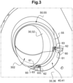
- the figure 3 illustrates an exemplary embodiment comprising several fasteners 60.
- the cover 35 is made locally transparent to allow the fasteners 60 to be viewed.
- Each fastener 60 comprises a first support 61, a second support 62 and a connecting clip 63. Furthermore, each fastener 60, and in particular its connecting clip 63, is accessible to an operator via the space 41.
Landscapes
- Engineering & Computer Science (AREA)
- Mechanical Engineering (AREA)
- Chemical & Material Sciences (AREA)
- Combustion & Propulsion (AREA)
- Aviation & Aerospace Engineering (AREA)
- General Engineering & Computer Science (AREA)
- Exhaust Silencers (AREA)
- Jet Pumps And Other Pumps (AREA)
- Cooling, Air Intake And Gas Exhaust, And Fuel Tank Arrangements In Propulsion Units (AREA)
Description
- La présente invention concerne un aéronef muni d'un conduit d'échappement couplé à un système de stabilisation qui est configuré pour stabiliser le conduit d'échappement.
- Un aéronef, et par exemple un giravion, peut comprendre un moteur qui expulse des gaz de combustion par une tuyère d'éjection.
- Le moteur est usuellement logé dans un compartiment de l'aéronef dénommé « compartiment moteur ». Le compartiment moteur peut être délimité par une ou des cloisons pare-feu et/ou au moins un capot.
- L'aéronef peut alors comprendre un conduit d'échappement qui est ouvert sur le compartiment moteur et sur un milieu extérieur à l'aéronef. Le conduit d'échappement peut être fixé et disposé dans un logement délimité par un capot mobile, voire une cloison pare-feu par exemple. Ce conduit d'échappement entoure localement la tuyère d'éjection. Ce conduit d'échappement peut permettre de mélanger les gaz de combustion issus de la tuyère d'éjection d'un moteur avec de l'air frais provenant du compartiment moteur et/ou de diriger les gaz vers des zones préférentielles. La tuyère d'éjection peut être qualifiée de tuyère primaire ou principale, le conduit d'échappement pouvant être qualifié de tuyère secondaire.
- En outre, le développement d'un conduit d'échappement est complexe en raison notamment de la température élevée des gaz éjectés, de l'ordre de plusieurs centaines de degrés Celsius, de la pression exercée par ces gaz sur le conduit d'échappement ainsi que des phénomènes vibratoires.
- Par exemple, la rotation d'un rotor principal d'un hélicoptère, le fonctionnement d'un moteur et une structure portant le conduit d'échappement sont des sources de vibrations susceptibles d'exciter un conduit d'échappement. Le déplacement de l'air à proximité du conduit d'échappement est aussi une source de vibrations pour ce conduit d'échappement.
- Dès lors, un conduit d'échappement est susceptible de se déformer en vol en raison de ces diverses contraintes, notamment en raison des contraintes thermiques ainsi que de son comportement vibratoire et dynamique et du calage de sa fréquence propre au regard des fréquences des excitations subies.
- La modification du conduit d'échappement pour limiter ces déformations subies peut être relativement délicate, en termes de coût financier, de temps, voire de masse. En outre, la modification d'un conduit d'échappement peut avoir un impact sur son environnement, et par exemple sur la structure porteuse devant porter le conduit d'échappement.
- Le document
EP3575219 décrit un giravion ayant au moins un moteur associé à un conduit d'échappement. Le conduit d'échappement est fixé à une structure fixe du giravion par un mécanisme pour être stabilisé statiquement ainsi que suite à une dilatation thermique. - Le document
EP2894099 décrit un procédé de fabrication d'un conduit d'échappement muni d'anneaux de fixation. - Le document
WO2009/083074A1 décrit un dispositif permettant de refroidir un gaz chaud devant être évacué d'un avion, lequel dispositif comprend un canal conçu pour conduire le gaz chaud d'une source de gaz chaud pouvant être reliée au dispositif à un point de sortie, ainsi qu'un bâti qui entoure le canal et qui est conçu pour maintenir ce canal. Le canal est constitué d'une ou de plusieurs sections de tube et présente un ou plusieurs points d'entrée d'air de refroidissement qui peuvent être raccordés à une ou plusieurs sources d'air de refroidissement afin de mélanger le gaz chaud à de l'air de refroidissement. Les documentsWO 99/54204 A1 US 2 653 585 A sont aussi connus. - La présente invention a alors pour objet de proposer un aéronef selon la revendication 1 qui est muni d'un conduit d'échappement coopérant avec un système de stabilisation innovant.
- L'invention vise un aéronef muni d'au moins un conduit d'échappement pour éjecter des gaz provenant d'un moteur, le conduit d'échappement étant logé partiellement dans un logement interne de l'aéronef, le logement étant séparé d'un milieu extérieur situé en dehors de l'aéronef par au moins un capot, ce capot étant mobile par rapport à une structure porteuse de l'aéronef, le conduit d'échappement comprenant un tronçon éjecteur traversant un passage du capot sans toucher le capot, un espace séparant le tronçon éjecteur du capot.
- Cet aéronef comporte selon cette revendication 1 au moins un système de stabilisation couplé au conduit d'échappement, le système de stabilisation comprenant un anneau raidisseur solidarisé au conduit d'échappement et au moins une fixation connectant le conduit d'échappement au capot. Ainsi, le système de stabilisation comporte deux dispositifs dissimilaires qui fonctionnent en synergie pour améliorer, en utilisation, le comportement du conduit d'échappement au regard des contraintes subies. Des caractéristiques optionnelles de cet aéronef sont décrites dans les revendications dépendantes 2-13.
- Un anneau raidisseur est positionné autour du conduit d'échappement, et contre ce conduit d'échappement. En particulier, l'anneau raidisseur permet de modifier la fréquence propre du conduit d'échappement pour l'éloigner d'une fréquence d'excitation. L'anneau raidisseur permet aussi de contraindre localement le conduit d'échappement pour éviter sa déformation, par exemple en évitant une ovalisation du conduit d'échappement. Cet anneau raidisseur peut être agencé de manière à avoir un impact acceptable sur l'aérodynamique de l'aéronef, voire sur la ventilation du logement.
- La ou les fixations permettent de fixer le conduit d'échappement au capot afin de stabiliser ce conduit d'échappement en vol. La ou les fixations peuvent être définies pour ne pas entraver l'expansion thermique du conduit d'échappement en fonctionnement tout en contraignant son déplacement dans le référentiel de l'aéronef. La ou les fixations peuvent de plus être définies pour autoriser une désolidarisation rapide du conduit d'échappement et du capot, et ainsi pour autoriser l'ouverture du capot.
- Ce système de stabilisation peut avoir un impact massique faible, n'a pas d'impact sur l'environnement du conduit d'échappement à l'exception du capot et peut être installé sur un aéronef existant durant une campagne dite de « retrofit » en langue anglaise.
- L'aéronef peut de plus comprendre une ou plusieurs des caractéristiques qui suivent notamment, prises seules ou en combinaison.
- Ainsi, l'anneau raidisseur peut entourer le conduit d'échappement.
- L'anneau raidisseur peut entourer une section du conduit d'échappement, à savoir totalement et donc à 360 degrés autour d'un volume interne du conduit d'échappement.
- Alternativement, l'anneau raidisseur peut s'étendre sur un angle inférieur à 360 degrés autour d'un axe géométrique, et donc du volume interne. L'anneau raidisseur entoure alors seulement partiellement le conduit d'échappement.
- Selon une possibilité compatible avec les précédentes, l'anneau raidisseur peut être disposé autour du tronçon éjecteur.
- L'anneau raidisseur génère une pression sur le conduit d'échappement lorsque ce conduit d'échappement se dilate sous l'effet de la température des gaz. La pression générée par l'anneau raidisseur sur le conduit d'échappement peut être optimisée lorsque l'anneau raidisseur est disposé sur le tronçon éjecteur qui est susceptible de subir une dilatation thermique plus faible qu'un tronçon d'entrée du conduit d'échappement par exemple. En outre, l'anneau raidisseur tend à raidir le tronçon éjecteur qui est susceptible de se déformer au sein d'un conduit d'échappement usuel.
- Selon une possibilité compatible avec les précédentes, l'anneau raidisseur peut être disposé au moins partiellement dans le milieu extérieur.
- L'impact sur l'aérodynamisme de l'aéronef est ainsi limité. L'anneau raidisseur reste agencé au plus près, voire sur le tronçon du conduit d'échappement qui est susceptible de se déformer au sein d'un conduit d'échappement usuel.
- Alternativement et en fonction des besoins, l'anneau raidisseur peut être disposé totalement dans le milieu extérieur.
- Selon une possibilité compatible avec les précédentes, l'anneau raidisseur peut comporter un profil en L, T, en C ou en oméga. La forme en oméga peut comprendre une branche sensiblement plane, suivie d'une forme sensiblement de C arrondie ou non et basculée de 90 degrés vers la droite puis d'une autre branche sensiblement plane.
- Un tel profil peut être suffisant pour modifier de manière adéquate le comportement du conduit d'échappement.
- Selon une possibilité compatible avec les précédentes, l'anneau raidisseur peut être fixé au conduit d'échappement par des attaches de raidissement dissociables.
- Le terme « dissociables » désigne des attaches pouvant être enlevées sans dégrader l'anneau raidisseur et/ou le conduit d'échappement durant une campagne de maintenance.
- Par exemple, les attaches de raidissement comportent des rivets ou autres.
- Selon une possibilité compatible avec les précédentes, ladite au moins une fixation peut comporter un premier support solidaire du conduit d'échappement et un deuxième support solidaire du capot, ladite au moins une fixation comprenant une attache de liaison fixant le premier support au deuxième support.
- L'attache de liaison peut être une attache dite rapide. Selon des exemples donnés à titre d'illustration, l'attache de liaison peut comprendre une attache quart de tour voire une fixation connue sous la marque dzus® par exemple. Un opérateur peut alors facilement dissocier le conduit d'échappement et le capot.
- Selon une possibilité compatible avec les précédentes, ladite au moins une fixation peut être agencée au moins partiellement dans ledit logement.
- La fixation peut être intégralement logée dans le logement ou peut s'étendre en dehors du logement. Par exemple, la fixation précitée peut être localisée dans le milieu extérieur.
- Selon une possibilité compatible avec les précédentes, ladite au moins une fixation peut être accessible via ledit espace séparant le tronçon éjecteur du capot.
- L'espace peut présenter des dimensions supérieures à des dimensions d'une main humaine ou d'un outil apte à ouvrir la fixation.
- A titre illustratif, l'espace peut présenter une dimension au moins supérieure à 5 centimètres.
- L'agencement du conduit d'échappement dans un passage du capot ayant des dimensions plus importantes permet de ménager un espace pouvant être traversé par un outil et/ou une main. Un opérateur peut introduire une main dans l'espace pour désolidariser le conduit d'échappement du capot, afin d'ouvrir le capot par exemple.
- Selon une possibilité compatible avec les précédentes, ladite au moins une fixation peut être adjacente à l'anneau raidisseur.
- La ou les fixations sont au plus près de l'anneau raidisseur pour apporter des points de fixation et de la raideur sensiblement au même endroit.
- Eventuellement, au moins une fixation peut être fixée à l'anneau raidisseur.
- La fixation connecte ainsi le conduit d'échappement au capot via l'anneau raidisseur.
- Alternativement, la fixation peut être fixée directement au conduit d'échappement.
- Selon une possibilité compatible avec les précédentes, ladite au moins une fixation peut comporter plusieurs fixations disposées autour du conduit d'échappement.
- Les fixations sont alors réparties, de manière iso-répartie ou non iso-répartie, autour du conduit d'échappement pour stabiliser le conduit d'échappement en plusieurs zones et selon plusieurs axes géométriques.
- L'invention et ses avantages apparaîtront avec plus de détails dans le cadre de la description qui suit avec des exemples donnés à titre illustratif en référence aux figures annexées qui représentent :
- la
figure 1 , un schéma en couple illustrant un aéronef selon l'invention, - la
figure 2 , un schéma en coupe illustrant un aéronef selon l'invention, et - la
figure 3 , une vue présentant partiellement un aéronef selon l'invention. - Les éléments présents dans plusieurs figures distinctes sont affectés d'une seule et même référence.
- La
figure 1 présente un aéronef 1 selon l'invention. - Un tel aéronef 1 comprend une structure porteuse 3 portant au moins un moteur 10. Le moteur 10 est en particulier disposé dans un compartiment moteur 5.
- Le compartiment moteur 5 est délimité par au moins une paroi 6, 7, 8 et 9. La ou les parois 6, 7, 8 et 9 peuvent être des parois anti-feu, par exemple ignifugées. Par exemple, le compartiment moteur 5 est délimité selon un axe longitudinal par au moins une paroi longitudinale 6, 8. Par exemple, le compartiment moteur 5 est délimité selon un axe transversal par au moins une paroi transversale 7 et un capotage, et verticalement au moins par une paroi de fond 9.
- Le ou les moteurs 10 peuvent être des moteurs thermiques aptes à brûler un carburant pour mettre en mouvement chaque arbre de puissance. Selon une possibilité, le ou les moteurs 10 peuvent être des turbomoteurs. Alternativement, le ou les moteurs 10 peuvent être des moteurs à pistons par exemple.
- Indépendamment de la nature du ou des moteurs 10 et de leur agencement, chaque moteur 10 comporte une tuyère d'éjection 20 pour au moins éjecter selon la flèche F1 des gaz résultant de la combustion du carburant dans le moteur 10 considéré. Par exemple, la tuyère d'éjection 20 traverse une paroi longitudinale 6.
- Dès lors, un conduit d'échappement 30 selon l'invention entoure au moins partiellement la tuyère d'éjection 20, à savoir toute la tuyère d'éjection 20 ou un tronçon de la tuyère d'éjection 20 et par exemple au minimum une portion d'éjection de la tuyère d'éjection 20 par laquelle des gaz sont expulsés. Par exemple, le conduit d'échappement 30 entoure au moins une partie de la tuyère d'éjection 20 située en dehors du compartiment moteur 5.
- Le conduit d'échappement 30 peut comprendre une paroi périphérique. La paroi périphérique délimite un volume interne situé à l'intérieur du conduit d'échappement 30 et accueillant au moins un tronçon de la tuyère d'éjection 20.
- Par ailleurs, le conduit d'échappement 30 s'étend d'une section d'entrée 301, débouchant éventuellement sur le compartiment moteur 5, jusqu'à une section de sortie 302, débouchant éventuellement sur un milieu EXT situé à l'extérieur de l'aéronef 1. Dès lors, de l'air présent dans le compartiment 5 peut être aspiré dans le conduit d'échappement 30, puis est expulsé en dehors du véhicule avec des gaz provenant de la tuyère d'éjection 20 par la section de sortie 302.
- En particulier, le conduit d'échappement peut comprendre un tronçon d'entrée 31 comprenant la section d'entrée 301, puis un tronçon éjecteur 32 comprenant la section de sortie 302.
- Par ailleurs, le conduit d'échappement 30 est logé partiellement dans un logement 25 interne de l'aéronef 1.
- Telle qu'illustrée sur la
figure 1 , la section d'entrée du conduit peut être fixée à une paroi délimitant le logement, et par exemple la paroi 8. - Hors cas de déformation ou de vibrations, le conduit d'échappement 30 peut être immobile dans le référentiel de l'aéronef et dans le logement 25.
- Ce logement 25 est notamment séparé du milieu extérieur EXT au moins par un capot 35. Le capot 35 est mobile par rapport à la structure porteuse 3 de l'aéronef 1, et au conduit d'échappement. A cet effet, le capot 35 peut être connecté à la structure porteuse 3 par au moins un système de mobilité 38, 39 illustré schématiquement. Un tel système de mobilité 38,39 peut comprendre au moins un rail, au moins un coulisseau, au moins une charnière par exemple.
- Le capot 35 peut comprendre un panneau de capotage 36. Le capot 35 peut comprendre un carter de protection 37 solidaire du panneau de capotage 36 tel qu'illustré sur la
figure 2 décrites par la suite. - Indépendamment des composants du capot 35 et des systèmes de mobilité 38, 39 le rendant mobile par rapport à la structure porteuse 3, le capot 35 comporte un passage 40. Un tel passage 40 peut comprendre une découpe réalisée dans le panneau de capotage 36, et le cas échéant non obturé par le carter de protection 37.
- Dès lors, le tronçon éjecteur 32 du conduit d'échappement 30 traverse le passage 40 du capot 35 sans toucher ce capot 35. Le tronçon éjecteur peut ainsi s'étendre dans le milieu extérieur EXT. Un espace 41 sépare donc le tronçon éjecteur 32 du capot 35. Cet espace 41 est un espace annulaire qui entoure le conduit d'échappement en le séparant d'un bord délimitant le passage 40.
- Selon un autre aspect, l'aéronef 1 comporte au moins un système de stabilisation 50 couplé à un conduit d'échappement 30. En présence de plusieurs moteurs 10 et de plusieurs conduits d'échappement 30 respectifs, chaque conduit d'échappement 30 est couplé à son propre système de stabilisation 50.
- Indépendamment du nombre de systèmes de stabilisation 50, un tel système de stabilisation 50 permet de modifier le comportement dynamique et vibratoire du conduit d'échappement 30, sans contrainte sur la structure porteuse 3 ou le compartiment moteur 5 par exemple.
- Un tel système de stabilisation 50 comprend un anneau raidisseur 55 qui est accolé au conduit d'échappement 30. L'anneau raidisseur peut entourer totalement le conduit d'échappement, à savoir à 360 degrés autour d'un axe géométrique, ou peut entourer partiellement le conduit d'échappement.
- Cet anneau raidisseur 55 est ainsi rendu solidaire au conduit d'échappement 30.
- Par exemple, l'anneau raidisseur 55 est agencé contre le tronçon éjecteur 32.
- Eventuellement, l'anneau raidisseur 55 peut être disposé au moins partiellement dans le milieu extérieur EXT.
- Selon une variante, l'anneau raidisseur 55 et le conduit d'échappement 30 forment une seule et même pièce, l'anneau raidisseur 55 et le conduit d'échappement 30 étant indissociables sans casse. Par exemple, l'anneau raidisseur 55 est soudé au conduit d'échappement 30.
- Selon une autre variante, l'anneau raidisseur 55 est fixé au conduit d'échappement 30 par des attaches de raidissement 56 dissociables. Selon une illustration de cette possibilité, les attaches de raidissement 56 comprennent des rivets.
- Selon une autre caractéristique, l'anneau raidisseur 55 peut avoir un profil en L, en T, en C ou en oméga. Un tel anneau raidisseur 55 permet de modifier la fréquence propre du conduit d'échappement 30 relativement facilement et à moindre coût.
- Quelle que soit la manière de réaliser l'anneau raidisseur 55, le système de stabilisation 50 comporte aussi une ou des fixations 60 connectant le conduit d'échappement 30 au capot 35. Au moins une fixation 60 peut notamment être fixée au tronçon éjecteur 32. Selon les exemples illustrés, le système de stabilisation 50 comporte plusieurs fixations 60 disposées autour du conduit d'échappement 30.
- Selon l'exemple de la
figure 1 , au moins une fixation 60 peut notamment être fixée au panneau de capotage 36 du capot 35. - De manière complémentaire ou alternative et en référence à la
figure 2 , au moins une fixation 60 peut notamment être fixée au carter de protection 37 du capot 35. - Quel que soit l'organe du capot 35 fixé à une fixation 60, au moins une fixation 60 est éventuellement positionnée afin d'être adjacente à l'anneau raidisseur 55.
- Eventuellement, au moins une fixation 60 peut être fixée à l'anneau raidisseur 55.
- Quel que soit le positionnement d'une fixation 60, cette fixation 60 peut comporter un premier support 61 et un deuxième support 62 assemblés l'un à l'autre par une attache de liaison 63.
- Par exemple, le premier support 61 est solidaire du conduit d'échappement 30, directement ou via l'anneau raidisseur 55. Le premier support 61 peut être fixé au conduit d'échappement 30 ou à l'anneau raidisseur 55 par vissage, rivetage, collage, soudure, etc...
- Par exemple, le deuxième support 62 est solidaire du capot 35. Le deuxième support 62 peut être fixé au capot 35 par vissage, rivetage, collage, soudure, etc...
- En outre, le premier support 61 peut comprendre une chape mâle ou femelle comprenant au moins un premier orifice. De même, le deuxième support 62 peut comprendre une chape mâle ou femelle comprenant au moins un deuxième orifice. L'attache de liaison 63 comporte alors notamment une liaison traversant le ou les premiers orifices et le ou les deuxièmes orifices.
- Selon un autre aspect, une fixation 60 peut se trouver au moins partiellement dans le logement 25. Par exemple, le premier support 61 d'une fixation 60 peut s'étendre en partie dans le milieu extérieur EXT, et le deuxième support 62 peut se trouver dans le logement 25. Selon une autre alternative optimisée d'un point de vue aérodynamique, toute la fixation 60 est agencée dans le logement 25. Alternativement, au moins une fixation 60 peut être entièrement dans le milieu extérieur EXT.
- Eventuellement, au moins une fixation 60 est accessible à un opérateur via l'espace 41.
- Dans ce contexte, la
figure 3 illustre un exemple de réalisation comprenant plusieurs fixations 60. Le capot 35 est rendu localement transparent pour permettre de visualiser les fixations 60. - Chaque fixation 60 comporte un premier support 61, un deuxième support 62 et une attache de liaison 63. En outre, chaque fixation 60, et notamment son attache de liaison 63, est accessible à un opérateur via l'espace 41.
- Naturellement, la présente invention est sujette à de nombreuses variations quant à sa mise en oeuvre. Bien que plusieurs modes de réalisation aient été décrits, on comprend bien qu'il n'est pas concevable d'identifier de manière exhaustive tous les modes possibles.
Claims (13)
- Aéronef (1) muni d'au moins un conduit d'échappement (30) pour éjecter des gaz provenant d'un moteur (10), le conduit d'échappement (30) étant logé partiellement dans un logement (25) interne de l'aéronef (1), le logement (25) étant séparé d'un milieu extérieur (EXT) situé en dehors de l'aéronef (1) par au moins un capot (35), le capot (35) étant mobile par rapport à une structure porteuse (3) de l'aéronef (1), le conduit d'échappement (30) comprenant un tronçon éjecteur (32) traversant un passage (40) du capot (35) sans toucher le capot (35), un espace (41) séparant le tronçon éjecteur (32) du capot (35), l'aéronef (1) comportant au moins un système de stabilisation (50) couplé au conduit d'échappement (30), le système de stabilisation (50) comprenant un anneau raidisseur (55) solidarisé au conduit d'échappement (30) et au moins une fixation (60) connectant le conduit d'échappement (30) au capot (35).
- Aéronef selon la revendication 1,
caractérisé en ce que ledit anneau raidisseur (55) entoure le conduit d'échappement (30). - Aéronef selon la revendication 1,
caractérisé en ce que ledit anneau raidisseur (55) s'étend sur un angle inférieur à 360 degrés autour d'un axe géométrique. - Aéronef selon l'une quelconque des revendications 1 à 3,
caractérisé en ce que ledit anneau raidisseur (55) est disposé autour du tronçon éjecteur (32). - Aéronef selon l'une quelconque des revendications 1 à 4,
caractérisé en ce que ledit anneau raidisseur (55) est disposé au moins partiellement dans le milieu extérieur (EXT). - Aéronef selon l'une quelconque des revendications 1 à 5,
caractérisé en ce que ledit anneau raidisseur (55) comporte un profil en L, en T, en C ou en oméga. - Aéronef selon l'une quelconque des revendications 1 à 6,
caractérisé en ce que ledit anneau raidisseur (55) est fixé au conduit d'échappement (30) par des attaches de raidissement (56) dissociables. - Aéronef selon l'une quelconque des revendications 1 à 7,
caractérisé en ce que ladite au moins une fixation (60) comporte un premier support (61) solidaire du conduit d'échappement (30) et un deuxième support (62) solidaire du capot (35), ladite au moins une fixation (60) comprenant une attache de liaison (63) fixant le premier support (61) au deuxième support (62). - Aéronef selon l'une quelconque des revendications 1 à 8,
caractérisé en ce que ladite au moins une fixation (60) est agencée au moins partiellement dans ledit logement (25). - Aéronef selon l'une quelconque des revendications 1 à 9,
caractérisé en ce que ladite au moins une fixation (60) est accessible via ledit espace (41) séparant le tronçon éjecteur du capot. - Aéronef selon l'une quelconque des revendications 1 à 10,
caractérisé en ce que ladite au moins une fixation (60) est adjacente à l'anneau raidisseur (55). - Aéronef selon l'une quelconque des revendications 1 à 11,
caractérisé en ce que ladite fixation (60) est fixée à l'anneau raidisseur (55). - Aéronef selon l'une quelconque des revendications 1 à 12,
caractérisé en ce que ladite au moins une fixation (60) comporte plusieurs fixations (60) disposées autour du conduit d'échappement (30).
Applications Claiming Priority (1)
| Application Number | Priority Date | Filing Date | Title |
|---|---|---|---|
| FR2211666A FR3141681B1 (fr) | 2022-11-09 | 2022-11-09 | Aéronef muni d’un conduit d’échappement couplé à un système de stabilisation |
Publications (2)
| Publication Number | Publication Date |
|---|---|
| EP4368515A1 EP4368515A1 (fr) | 2024-05-15 |
| EP4368515B1 true EP4368515B1 (fr) | 2025-01-15 |
Family
ID=85685614
Family Applications (1)
| Application Number | Title | Priority Date | Filing Date |
|---|---|---|---|
| EP23200550.4A Active EP4368515B1 (fr) | 2022-11-09 | 2023-09-28 | Aéronef muni d'un conduit d'échappement couplé à un système de stabilisation |
Country Status (3)
| Country | Link |
|---|---|
| US (1) | US12466570B2 (fr) |
| EP (1) | EP4368515B1 (fr) |
| FR (1) | FR3141681B1 (fr) |
Families Citing this family (4)
| Publication number | Priority date | Publication date | Assignee | Title |
|---|---|---|---|---|
| US20250243783A1 (en) * | 2024-01-25 | 2025-07-31 | Rtx Corporation | Intermediate case for aircraft propulsion system housing |
| US12617541B1 (en) | 2024-12-19 | 2026-05-05 | Pratt & Whitney Canada Corp. | Exhaust case for aircraft engine |
| US12618342B1 (en) | 2025-05-07 | 2026-05-05 | Pratt & Whitney Canada Corp. | Turbine exhaust case with stiffening brace |
| US12529325B1 (en) | 2025-07-29 | 2026-01-20 | Pratt & Whitney Canada Corp. | Turbine exhaust duct with stiffeners for aircraft engines |
Family Cites Families (24)
| Publication number | Priority date | Publication date | Assignee | Title |
|---|---|---|---|---|
| US2653585A (en) * | 1949-12-22 | 1953-09-29 | United Aircraft Corp | Engine cooling and exhaust arrangement |
| US2846844A (en) * | 1956-01-24 | 1958-08-12 | Ryan Aeronautical Co | Variable area thrust deflectoraugmenter for jet engines |
| GB918189A (en) * | 1960-07-01 | 1963-02-13 | Rolls Royce | Jet propulsion nozzle |
| US3693880A (en) * | 1970-11-02 | 1972-09-26 | Us Navy | Infrared suppressor means |
| US4073440A (en) * | 1976-04-29 | 1978-02-14 | The Boeing Company | Combination primary and fan air thrust reversal control systems for long duct fan jet engines |
| US4215537A (en) * | 1978-07-27 | 1980-08-05 | Avco Corporation | Apparatus for and method of suppressing infrared radiation emitted from gas turbine engine |
| US6109562A (en) * | 1998-04-22 | 2000-08-29 | Pratt & Whitney Canada Corp. | Aircraft construction |
| US20020092948A1 (en) * | 2001-01-16 | 2002-07-18 | Dugan John J. | Apparatus and method for reducing jet engine noise |
| JP4709433B2 (ja) * | 2001-06-29 | 2011-06-22 | 三菱重工業株式会社 | ガスタービン燃焼器 |
| DE07873413T1 (de) * | 2006-06-09 | 2009-07-30 | Bell Helicopter Textron, Inc., Fort Worth | Motorenabgassystem mit direktionaler düse |
| DE102007061995B4 (de) * | 2007-12-21 | 2012-03-01 | Airbus Operations Gmbh | Vorrichtung zum mechanisch entkoppelten Befestigen einer von Heißgas durchströmten Flugzeugkomponente |
| DE102007061994B4 (de) * | 2007-12-21 | 2016-11-03 | Airbus Operations Gmbh | Vorrichtung zum Kühlen von aus einem Flugzeug abzuführendem Heißgas |
| FR2928900B1 (fr) * | 2008-03-20 | 2010-03-19 | Airbus France | Dispositif pour reduire les emissions infrarouge d'un turbopropulseur. |
| US9052016B2 (en) * | 2011-10-24 | 2015-06-09 | United Technologies Corporation | Variable width gap seal |
| US9382875B2 (en) * | 2012-08-15 | 2016-07-05 | United Technologies Corporation | Spherical button washer for exhaust duct liner hanger |
| US9638133B2 (en) * | 2012-11-28 | 2017-05-02 | United Technologies Corporation | Ceramic matrix composite liner attachment |
| US9434477B2 (en) | 2014-01-08 | 2016-09-06 | The Boeing Company | Duct apparatus for use with aircraft and related methods |
| PL417165A1 (pl) * | 2016-05-12 | 2017-11-20 | Mra Systems, Inc. | Zespół odwracacza ciągu |
| US10279924B2 (en) * | 2017-05-12 | 2019-05-07 | Bell Helicopter Textron Inc. | Engine exhaust duct mounting assembly |
| US11028944B2 (en) | 2018-05-31 | 2021-06-08 | Textron Innovations Inc. | Duct support |
| US11047308B2 (en) * | 2018-06-29 | 2021-06-29 | The Boeing Company | Acoustic panel for thrust reversers |
| US11300075B2 (en) * | 2019-03-12 | 2022-04-12 | Rohr, Inc. | Engine exhaust skin connection system |
| US11187098B2 (en) * | 2019-12-20 | 2021-11-30 | Rolls-Royce Corporation | Turbine shroud assembly with hangers for ceramic matrix composite material seal segments |
| US11788491B1 (en) * | 2022-07-13 | 2023-10-17 | General Electric Company | Systems and methods for attachment of materials having different thermal expansion coefficients |
-
2022
- 2022-11-09 FR FR2211666A patent/FR3141681B1/fr active Active
-
2023
- 2023-09-28 EP EP23200550.4A patent/EP4368515B1/fr active Active
- 2023-10-16 US US18/380,289 patent/US12466570B2/en active Active
Also Published As
| Publication number | Publication date |
|---|---|
| US12466570B2 (en) | 2025-11-11 |
| EP4368515A1 (fr) | 2024-05-15 |
| US20240150030A1 (en) | 2024-05-09 |
| FR3141681B1 (fr) | 2025-03-21 |
| FR3141681A1 (fr) | 2024-05-10 |
Similar Documents
| Publication | Publication Date | Title |
|---|---|---|
| EP4368515A1 (fr) | Aeronef muni d'un conduit d'echappement couple a un systeme de stabilisation | |
| CA2933353C (fr) | Turbomachine d'aeronef comportant un echangeur de chaleur du type pre-refroidisseur | |
| EP1881179B1 (fr) | Système de ventilation de paroi de chambre de combustion dans une turbomachine | |
| EP1840028B1 (fr) | Système de dégivrage d'un cone d'entrée de turbomoteur pour aéronef | |
| FR2706534A1 (fr) | Diffuseur-séparateur multiflux avec redresseur intégré pour turboréacteur. | |
| EP3039341B1 (fr) | Chambre de combustion de turbomachine pourvue de moyens de déflection d'air pour réduire le sillage creé par une bougie d'allumage | |
| EP1265030A1 (fr) | Accrochage de chambre de combustion CMC de turbomachine par viroles de liaison souples | |
| EP2245314B1 (fr) | Diffuseur de turbomachine comportant des voiles annulaires echancres | |
| CA2875044C (fr) | Carter pour un ensemble propulsif | |
| FR3043723A1 (fr) | Ensemble de propulsion d'un aeronef comportant un generateur de gaz, deux soufflantes deportees et une manche d'entree d'air | |
| EP3945033A1 (fr) | Ensemble propulsif pour aéronef | |
| FR3001199A1 (fr) | Capot de moteur incorporant un circuit de ventilation d'equipement | |
| EP2247503B1 (fr) | Structure d'accrochage pour turboréacteur | |
| FR3043653A1 (fr) | Ensemble de propulsion d'un aeronef comportant un generateur de gaz et deux soufflantes deportees | |
| EP2644505B1 (fr) | Carénage aérodynamique arrière à tenue en température améliorée pour mât d'accrochage d'ensemble propulsif d'aéronef | |
| EP1903283B1 (fr) | Chambre de combustion annulaire d'une turbomachine | |
| US20150330255A1 (en) | Anti-torsion assembly with wedge-shaped torque block | |
| EP2828513B1 (fr) | Cône d'éjection des gaz pour turboréacteurs d'aéronefs | |
| WO2009133322A1 (fr) | Chambre annulaire de combustion pour turbomachine | |
| FR2951701A1 (fr) | Ensemble moteur pour aeronef comprenant un bord d'attaque de mat d'accrochage chauffe par un liquide caloporteur a effet anti-givrage | |
| FR3142454A1 (fr) | Entree d’air de nacelle de turboreacteur a montage ameliore | |
| FR3087840A1 (fr) | Capot de nacelle pour ensemble propulsif d'aeronef | |
| FR3095229A1 (fr) | Ensemble pour flux primaire de turbomachine aéronautique, turbomachine munie de celui-ci | |
| FR2978982A1 (fr) | Moyens de renfort d'un conduit de soufflante d'une turbomachine | |
| FR2934247A1 (fr) | Nacelle de turboreacteur. |
Legal Events
| Date | Code | Title | Description |
|---|---|---|---|
| PUAI | Public reference made under article 153(3) epc to a published international application that has entered the european phase |
Free format text: ORIGINAL CODE: 0009012 |
|
| STAA | Information on the status of an ep patent application or granted ep patent |
Free format text: STATUS: THE APPLICATION HAS BEEN PUBLISHED |
|
| AK | Designated contracting states |
Kind code of ref document: A1 Designated state(s): AL AT BE BG CH CY CZ DE DK EE ES FI FR GB GR HR HU IE IS IT LI LT LU LV MC ME MK MT NL NO PL PT RO RS SE SI SK SM TR |
|
| STAA | Information on the status of an ep patent application or granted ep patent |
Free format text: STATUS: REQUEST FOR EXAMINATION WAS MADE |
|
| 17P | Request for examination filed |
Effective date: 20240517 |
|
| P01 | Opt-out of the competence of the unified patent court (upc) registered |
Effective date: 20240517 |
|
| RBV | Designated contracting states (corrected) |
Designated state(s): AL AT BE BG CH CY CZ DE DK EE ES FI FR GB GR HR HU IE IS IT LI LT LU LV MC ME MK MT NL NO PL PT RO RS SE SI SK SM TR |
|
| GRAP | Despatch of communication of intention to grant a patent |
Free format text: ORIGINAL CODE: EPIDOSNIGR1 |
|
| STAA | Information on the status of an ep patent application or granted ep patent |
Free format text: STATUS: GRANT OF PATENT IS INTENDED |
|
| INTG | Intention to grant announced |
Effective date: 20241017 |
|
| GRAS | Grant fee paid |
Free format text: ORIGINAL CODE: EPIDOSNIGR3 |
|
| GRAA | (expected) grant |
Free format text: ORIGINAL CODE: 0009210 |
|
| STAA | Information on the status of an ep patent application or granted ep patent |
Free format text: STATUS: THE PATENT HAS BEEN GRANTED |
|
| AK | Designated contracting states |
Kind code of ref document: B1 Designated state(s): AL AT BE BG CH CY CZ DE DK EE ES FI FR GB GR HR HU IE IS IT LI LT LU LV MC ME MK MT NL NO PL PT RO RS SE SI SK SM TR |
|
| REG | Reference to a national code |
Ref country code: CH Ref legal event code: EP Ref country code: GB Ref legal event code: FG4D Free format text: NOT ENGLISH |
|
| REG | Reference to a national code |
Ref country code: DE Ref legal event code: R096 Ref document number: 602023001685 Country of ref document: DE |
|
| REG | Reference to a national code |
Ref country code: IE Ref legal event code: FG4D Free format text: LANGUAGE OF EP DOCUMENT: FRENCH |
|
| REG | Reference to a national code |
Ref country code: NL Ref legal event code: MP Effective date: 20250115 |
|
| PG25 | Lapsed in a contracting state [announced via postgrant information from national office to epo] |
Ref country code: NL Free format text: LAPSE BECAUSE OF FAILURE TO SUBMIT A TRANSLATION OF THE DESCRIPTION OR TO PAY THE FEE WITHIN THE PRESCRIBED TIME-LIMIT Effective date: 20250115 |
|
| PG25 | Lapsed in a contracting state [announced via postgrant information from national office to epo] |
Ref country code: RS Free format text: LAPSE BECAUSE OF FAILURE TO SUBMIT A TRANSLATION OF THE DESCRIPTION OR TO PAY THE FEE WITHIN THE PRESCRIBED TIME-LIMIT Effective date: 20250415 |
|
| PG25 | Lapsed in a contracting state [announced via postgrant information from national office to epo] |
Ref country code: FI Free format text: LAPSE BECAUSE OF FAILURE TO SUBMIT A TRANSLATION OF THE DESCRIPTION OR TO PAY THE FEE WITHIN THE PRESCRIBED TIME-LIMIT Effective date: 20250115 |
|
| PG25 | Lapsed in a contracting state [announced via postgrant information from national office to epo] |
Ref country code: PL Free format text: LAPSE BECAUSE OF FAILURE TO SUBMIT A TRANSLATION OF THE DESCRIPTION OR TO PAY THE FEE WITHIN THE PRESCRIBED TIME-LIMIT Effective date: 20250115 |
|
| PG25 | Lapsed in a contracting state [announced via postgrant information from national office to epo] |
Ref country code: ES Free format text: LAPSE BECAUSE OF FAILURE TO SUBMIT A TRANSLATION OF THE DESCRIPTION OR TO PAY THE FEE WITHIN THE PRESCRIBED TIME-LIMIT Effective date: 20250115 |
|
| REG | Reference to a national code |
Ref country code: LT Ref legal event code: MG9D |
|
| PG25 | Lapsed in a contracting state [announced via postgrant information from national office to epo] |
Ref country code: NO Free format text: LAPSE BECAUSE OF FAILURE TO SUBMIT A TRANSLATION OF THE DESCRIPTION OR TO PAY THE FEE WITHIN THE PRESCRIBED TIME-LIMIT Effective date: 20250415 Ref country code: IS Free format text: LAPSE BECAUSE OF FAILURE TO SUBMIT A TRANSLATION OF THE DESCRIPTION OR TO PAY THE FEE WITHIN THE PRESCRIBED TIME-LIMIT Effective date: 20250515 |
|
| REG | Reference to a national code |
Ref country code: AT Ref legal event code: MK05 Ref document number: 1759728 Country of ref document: AT Kind code of ref document: T Effective date: 20250115 |
|
| PG25 | Lapsed in a contracting state [announced via postgrant information from national office to epo] |
Ref country code: HR Free format text: LAPSE BECAUSE OF FAILURE TO SUBMIT A TRANSLATION OF THE DESCRIPTION OR TO PAY THE FEE WITHIN THE PRESCRIBED TIME-LIMIT Effective date: 20250115 |
|
| PG25 | Lapsed in a contracting state [announced via postgrant information from national office to epo] |
Ref country code: LV Free format text: LAPSE BECAUSE OF FAILURE TO SUBMIT A TRANSLATION OF THE DESCRIPTION OR TO PAY THE FEE WITHIN THE PRESCRIBED TIME-LIMIT Effective date: 20250115 Ref country code: PT Free format text: LAPSE BECAUSE OF FAILURE TO SUBMIT A TRANSLATION OF THE DESCRIPTION OR TO PAY THE FEE WITHIN THE PRESCRIBED TIME-LIMIT Effective date: 20250515 |
|
| PG25 | Lapsed in a contracting state [announced via postgrant information from national office to epo] |
Ref country code: GR Free format text: LAPSE BECAUSE OF FAILURE TO SUBMIT A TRANSLATION OF THE DESCRIPTION OR TO PAY THE FEE WITHIN THE PRESCRIBED TIME-LIMIT Effective date: 20250416 Ref country code: BG Free format text: LAPSE BECAUSE OF FAILURE TO SUBMIT A TRANSLATION OF THE DESCRIPTION OR TO PAY THE FEE WITHIN THE PRESCRIBED TIME-LIMIT Effective date: 20250115 |
|
| PG25 | Lapsed in a contracting state [announced via postgrant information from national office to epo] |
Ref country code: AT Free format text: LAPSE BECAUSE OF FAILURE TO SUBMIT A TRANSLATION OF THE DESCRIPTION OR TO PAY THE FEE WITHIN THE PRESCRIBED TIME-LIMIT Effective date: 20250115 |
|
| PG25 | Lapsed in a contracting state [announced via postgrant information from national office to epo] |
Ref country code: SE Free format text: LAPSE BECAUSE OF FAILURE TO SUBMIT A TRANSLATION OF THE DESCRIPTION OR TO PAY THE FEE WITHIN THE PRESCRIBED TIME-LIMIT Effective date: 20250115 |
|
| PG25 | Lapsed in a contracting state [announced via postgrant information from national office to epo] |
Ref country code: SM Free format text: LAPSE BECAUSE OF FAILURE TO SUBMIT A TRANSLATION OF THE DESCRIPTION OR TO PAY THE FEE WITHIN THE PRESCRIBED TIME-LIMIT Effective date: 20250115 |
|
| PG25 | Lapsed in a contracting state [announced via postgrant information from national office to epo] |
Ref country code: DK Free format text: LAPSE BECAUSE OF FAILURE TO SUBMIT A TRANSLATION OF THE DESCRIPTION OR TO PAY THE FEE WITHIN THE PRESCRIBED TIME-LIMIT Effective date: 20250115 |
|
| PGFP | Annual fee paid to national office [announced via postgrant information from national office to epo] |
Ref country code: DE Payment date: 20250919 Year of fee payment: 3 |
|
| REG | Reference to a national code |
Ref country code: DE Ref legal event code: R097 Ref document number: 602023001685 Country of ref document: DE |
|
| PGFP | Annual fee paid to national office [announced via postgrant information from national office to epo] |
Ref country code: FR Payment date: 20250922 Year of fee payment: 3 |
|
| PG25 | Lapsed in a contracting state [announced via postgrant information from national office to epo] |
Ref country code: EE Free format text: LAPSE BECAUSE OF FAILURE TO SUBMIT A TRANSLATION OF THE DESCRIPTION OR TO PAY THE FEE WITHIN THE PRESCRIBED TIME-LIMIT Effective date: 20250115 Ref country code: CZ Free format text: LAPSE BECAUSE OF FAILURE TO SUBMIT A TRANSLATION OF THE DESCRIPTION OR TO PAY THE FEE WITHIN THE PRESCRIBED TIME-LIMIT Effective date: 20250115 |
|
| PG25 | Lapsed in a contracting state [announced via postgrant information from national office to epo] |
Ref country code: RO Free format text: LAPSE BECAUSE OF FAILURE TO SUBMIT A TRANSLATION OF THE DESCRIPTION OR TO PAY THE FEE WITHIN THE PRESCRIBED TIME-LIMIT Effective date: 20250115 |
|
| PG25 | Lapsed in a contracting state [announced via postgrant information from national office to epo] |
Ref country code: SK Free format text: LAPSE BECAUSE OF FAILURE TO SUBMIT A TRANSLATION OF THE DESCRIPTION OR TO PAY THE FEE WITHIN THE PRESCRIBED TIME-LIMIT Effective date: 20250115 |
|
| PLBE | No opposition filed within time limit |
Free format text: ORIGINAL CODE: 0009261 |
|
| STAA | Information on the status of an ep patent application or granted ep patent |
Free format text: STATUS: NO OPPOSITION FILED WITHIN TIME LIMIT |
|
| 26N | No opposition filed |
Effective date: 20251016 |
|
| PGFP | Annual fee paid to national office [announced via postgrant information from national office to epo] |
Ref country code: IT Payment date: 20250930 Year of fee payment: 3 |