EP4368432A1 - Vehicle-mounted structure for driving unit - Google Patents
Vehicle-mounted structure for driving unit Download PDFInfo
- Publication number
- EP4368432A1 EP4368432A1 EP21949269.1A EP21949269A EP4368432A1 EP 4368432 A1 EP4368432 A1 EP 4368432A1 EP 21949269 A EP21949269 A EP 21949269A EP 4368432 A1 EP4368432 A1 EP 4368432A1
- Authority
- EP
- European Patent Office
- Prior art keywords
- vehicle
- drive unit
- coolant
- exhaust pipe
- transmission
- Prior art date
- Legal status (The legal status is an assumption and is not a legal conclusion. Google has not performed a legal analysis and makes no representation as to the accuracy of the status listed.)
- Granted
Links
Images



Classifications
-
- B—PERFORMING OPERATIONS; TRANSPORTING
- B60—VEHICLES IN GENERAL
- B60H—ARRANGEMENTS OF HEATING, COOLING, VENTILATING OR OTHER AIR-TREATING DEVICES SPECIALLY ADAPTED FOR PASSENGER OR GOODS SPACES OF VEHICLES
- B60H1/00—Heating, cooling or ventilating devices
- B60H1/00507—Details, e.g. mounting arrangements, desaeration devices
- B60H1/00557—Details of ducts or cables
- B60H1/00571—Details of ducts or cables of liquid ducts, e.g. for coolant liquids or refrigerants
-
- B—PERFORMING OPERATIONS; TRANSPORTING
- B60—VEHICLES IN GENERAL
- B60L—PROPULSION OF ELECTRICALLY-PROPELLED VEHICLES; SUPPLYING ELECTRIC POWER FOR AUXILIARY EQUIPMENT OF ELECTRICALLY-PROPELLED VEHICLES; ELECTRODYNAMIC BRAKE SYSTEMS FOR VEHICLES IN GENERAL; MAGNETIC SUSPENSION OR LEVITATION FOR VEHICLES; MONITORING OPERATING VARIABLES OF ELECTRICALLY-PROPELLED VEHICLES; ELECTRIC SAFETY DEVICES FOR ELECTRICALLY-PROPELLED VEHICLES
- B60L50/00—Electric propulsion with power supplied within the vehicle
- B60L50/50—Electric propulsion with power supplied within the vehicle using propulsion power supplied by batteries or fuel cells
- B60L50/51—Electric propulsion with power supplied within the vehicle using propulsion power supplied by batteries or fuel cells characterised by AC-motors
-
- B—PERFORMING OPERATIONS; TRANSPORTING
- B60—VEHICLES IN GENERAL
- B60K—ARRANGEMENT OR MOUNTING OF PROPULSION UNITS OR OF TRANSMISSIONS IN VEHICLES; ARRANGEMENT OR MOUNTING OF PLURAL DIVERSE PRIME-MOVERS IN VEHICLES; AUXILIARY DRIVES FOR VEHICLES; INSTRUMENTATION OR DASHBOARDS FOR VEHICLES; ARRANGEMENTS IN CONNECTION WITH COOLING, AIR INTAKE, GAS EXHAUST OR FUEL SUPPLY OF PROPULSION UNITS IN VEHICLES
- B60K11/00—Arrangement in connection with cooling of propulsion units
- B60K11/02—Arrangement in connection with cooling of propulsion units with liquid cooling
-
- B—PERFORMING OPERATIONS; TRANSPORTING
- B60—VEHICLES IN GENERAL
- B60K—ARRANGEMENT OR MOUNTING OF PROPULSION UNITS OR OF TRANSMISSIONS IN VEHICLES; ARRANGEMENT OR MOUNTING OF PLURAL DIVERSE PRIME-MOVERS IN VEHICLES; AUXILIARY DRIVES FOR VEHICLES; INSTRUMENTATION OR DASHBOARDS FOR VEHICLES; ARRANGEMENTS IN CONNECTION WITH COOLING, AIR INTAKE, GAS EXHAUST OR FUEL SUPPLY OF PROPULSION UNITS IN VEHICLES
- B60K13/00—Arrangement in connection with combustion air intake or gas exhaust of propulsion units
- B60K13/04—Arrangement in connection with combustion air intake or gas exhaust of propulsion units concerning exhaust
-
- B—PERFORMING OPERATIONS; TRANSPORTING
- B60—VEHICLES IN GENERAL
- B60K—ARRANGEMENT OR MOUNTING OF PROPULSION UNITS OR OF TRANSMISSIONS IN VEHICLES; ARRANGEMENT OR MOUNTING OF PLURAL DIVERSE PRIME-MOVERS IN VEHICLES; AUXILIARY DRIVES FOR VEHICLES; INSTRUMENTATION OR DASHBOARDS FOR VEHICLES; ARRANGEMENTS IN CONNECTION WITH COOLING, AIR INTAKE, GAS EXHAUST OR FUEL SUPPLY OF PROPULSION UNITS IN VEHICLES
- B60K17/00—Arrangement or mounting of transmissions in vehicles
- B60K17/04—Arrangement or mounting of transmissions in vehicles characterised by arrangement, location or kind of gearing
-
- B—PERFORMING OPERATIONS; TRANSPORTING
- B60—VEHICLES IN GENERAL
- B60K—ARRANGEMENT OR MOUNTING OF PROPULSION UNITS OR OF TRANSMISSIONS IN VEHICLES; ARRANGEMENT OR MOUNTING OF PLURAL DIVERSE PRIME-MOVERS IN VEHICLES; AUXILIARY DRIVES FOR VEHICLES; INSTRUMENTATION OR DASHBOARDS FOR VEHICLES; ARRANGEMENTS IN CONNECTION WITH COOLING, AIR INTAKE, GAS EXHAUST OR FUEL SUPPLY OF PROPULSION UNITS IN VEHICLES
- B60K6/00—Arrangement or mounting of plural diverse prime-movers for mutual or common propulsion, e.g. hybrid propulsion systems comprising electric motors and internal combustion engines
- B60K6/20—Arrangement or mounting of plural diverse prime-movers for mutual or common propulsion, e.g. hybrid propulsion systems comprising electric motors and internal combustion engines the prime-movers consisting of electric motors and internal combustion engines, e.g. HEVs
- B60K6/22—Arrangement or mounting of plural diverse prime-movers for mutual or common propulsion, e.g. hybrid propulsion systems comprising electric motors and internal combustion engines the prime-movers consisting of electric motors and internal combustion engines, e.g. HEVs characterised by apparatus, components or means specially adapted for HEVs
- B60K6/40—Arrangement or mounting of plural diverse prime-movers for mutual or common propulsion, e.g. hybrid propulsion systems comprising electric motors and internal combustion engines the prime-movers consisting of electric motors and internal combustion engines, e.g. HEVs characterised by apparatus, components or means specially adapted for HEVs characterised by the assembly or relative disposition of components
- B60K6/405—Housings
-
- B—PERFORMING OPERATIONS; TRANSPORTING
- B60—VEHICLES IN GENERAL
- B60K—ARRANGEMENT OR MOUNTING OF PROPULSION UNITS OR OF TRANSMISSIONS IN VEHICLES; ARRANGEMENT OR MOUNTING OF PLURAL DIVERSE PRIME-MOVERS IN VEHICLES; AUXILIARY DRIVES FOR VEHICLES; INSTRUMENTATION OR DASHBOARDS FOR VEHICLES; ARRANGEMENTS IN CONNECTION WITH COOLING, AIR INTAKE, GAS EXHAUST OR FUEL SUPPLY OF PROPULSION UNITS IN VEHICLES
- B60K6/00—Arrangement or mounting of plural diverse prime-movers for mutual or common propulsion, e.g. hybrid propulsion systems comprising electric motors and internal combustion engines
- B60K6/20—Arrangement or mounting of plural diverse prime-movers for mutual or common propulsion, e.g. hybrid propulsion systems comprising electric motors and internal combustion engines the prime-movers consisting of electric motors and internal combustion engines, e.g. HEVs
- B60K6/42—Arrangement or mounting of plural diverse prime-movers for mutual or common propulsion, e.g. hybrid propulsion systems comprising electric motors and internal combustion engines the prime-movers consisting of electric motors and internal combustion engines, e.g. HEVs characterised by the architecture of the hybrid electric vehicle
- B60K6/46—Series type
-
- B—PERFORMING OPERATIONS; TRANSPORTING
- B60—VEHICLES IN GENERAL
- B60K—ARRANGEMENT OR MOUNTING OF PROPULSION UNITS OR OF TRANSMISSIONS IN VEHICLES; ARRANGEMENT OR MOUNTING OF PLURAL DIVERSE PRIME-MOVERS IN VEHICLES; AUXILIARY DRIVES FOR VEHICLES; INSTRUMENTATION OR DASHBOARDS FOR VEHICLES; ARRANGEMENTS IN CONNECTION WITH COOLING, AIR INTAKE, GAS EXHAUST OR FUEL SUPPLY OF PROPULSION UNITS IN VEHICLES
- B60K6/00—Arrangement or mounting of plural diverse prime-movers for mutual or common propulsion, e.g. hybrid propulsion systems comprising electric motors and internal combustion engines
- B60K6/20—Arrangement or mounting of plural diverse prime-movers for mutual or common propulsion, e.g. hybrid propulsion systems comprising electric motors and internal combustion engines the prime-movers consisting of electric motors and internal combustion engines, e.g. HEVs
- B60K6/50—Architecture of the driveline characterised by arrangement or kind of transmission units
- B60K6/54—Transmission for changing ratio
- B60K6/547—Transmission for changing ratio the transmission being a stepped gearing
-
- B—PERFORMING OPERATIONS; TRANSPORTING
- B60—VEHICLES IN GENERAL
- B60L—PROPULSION OF ELECTRICALLY-PROPELLED VEHICLES; SUPPLYING ELECTRIC POWER FOR AUXILIARY EQUIPMENT OF ELECTRICALLY-PROPELLED VEHICLES; ELECTRODYNAMIC BRAKE SYSTEMS FOR VEHICLES IN GENERAL; MAGNETIC SUSPENSION OR LEVITATION FOR VEHICLES; MONITORING OPERATING VARIABLES OF ELECTRICALLY-PROPELLED VEHICLES; ELECTRIC SAFETY DEVICES FOR ELECTRICALLY-PROPELLED VEHICLES
- B60L58/00—Methods or circuit arrangements for monitoring or controlling batteries or fuel cells, specially adapted for electric vehicles
- B60L58/10—Methods or circuit arrangements for monitoring or controlling batteries or fuel cells, specially adapted for electric vehicles for monitoring or controlling batteries
- B60L58/12—Methods or circuit arrangements for monitoring or controlling batteries or fuel cells, specially adapted for electric vehicles for monitoring or controlling batteries responding to state of charge [SoC]
-
- B—PERFORMING OPERATIONS; TRANSPORTING
- B60—VEHICLES IN GENERAL
- B60L—PROPULSION OF ELECTRICALLY-PROPELLED VEHICLES; SUPPLYING ELECTRIC POWER FOR AUXILIARY EQUIPMENT OF ELECTRICALLY-PROPELLED VEHICLES; ELECTRODYNAMIC BRAKE SYSTEMS FOR VEHICLES IN GENERAL; MAGNETIC SUSPENSION OR LEVITATION FOR VEHICLES; MONITORING OPERATING VARIABLES OF ELECTRICALLY-PROPELLED VEHICLES; ELECTRIC SAFETY DEVICES FOR ELECTRICALLY-PROPELLED VEHICLES
- B60L7/00—Electrodynamic brake systems for vehicles in general
- B60L7/10—Dynamic electric regenerative braking
- B60L7/14—Dynamic electric regenerative braking for vehicles propelled by AC motors
-
- F—MECHANICAL ENGINEERING; LIGHTING; HEATING; WEAPONS; BLASTING
- F16—ENGINEERING ELEMENTS AND UNITS; GENERAL MEASURES FOR PRODUCING AND MAINTAINING EFFECTIVE FUNCTIONING OF MACHINES OR INSTALLATIONS; THERMAL INSULATION IN GENERAL
- F16H—GEARING
- F16H57/00—General details of gearing
- F16H57/04—Features relating to lubrication or cooling or heating
- F16H57/0412—Cooling or heating; Control of temperature
- F16H57/0415—Air cooling or ventilation; Heat exchangers; Thermal insulations
- F16H57/0417—Heat exchangers adapted or integrated in the gearing
-
- F—MECHANICAL ENGINEERING; LIGHTING; HEATING; WEAPONS; BLASTING
- F16—ENGINEERING ELEMENTS AND UNITS; GENERAL MEASURES FOR PRODUCING AND MAINTAINING EFFECTIVE FUNCTIONING OF MACHINES OR INSTALLATIONS; THERMAL INSULATION IN GENERAL
- F16H—GEARING
- F16H57/00—General details of gearing
- F16H57/04—Features relating to lubrication or cooling or heating
- F16H57/0434—Features relating to lubrication or cooling or heating relating to lubrication supply, e.g. pumps; Pressure control
- F16H57/0443—Features relating to lubrication or cooling or heating relating to lubrication supply, e.g. pumps; Pressure control for supply of lubricant during tilt or high acceleration, e.g. problems related to the tilt or extreme acceleration of the transmission casing and the supply of lubricant under these conditions
-
- B—PERFORMING OPERATIONS; TRANSPORTING
- B60—VEHICLES IN GENERAL
- B60K—ARRANGEMENT OR MOUNTING OF PROPULSION UNITS OR OF TRANSMISSIONS IN VEHICLES; ARRANGEMENT OR MOUNTING OF PLURAL DIVERSE PRIME-MOVERS IN VEHICLES; AUXILIARY DRIVES FOR VEHICLES; INSTRUMENTATION OR DASHBOARDS FOR VEHICLES; ARRANGEMENTS IN CONNECTION WITH COOLING, AIR INTAKE, GAS EXHAUST OR FUEL SUPPLY OF PROPULSION UNITS IN VEHICLES
- B60K1/00—Arrangement or mounting of electrical propulsion units
-
- B—PERFORMING OPERATIONS; TRANSPORTING
- B60—VEHICLES IN GENERAL
- B60K—ARRANGEMENT OR MOUNTING OF PROPULSION UNITS OR OF TRANSMISSIONS IN VEHICLES; ARRANGEMENT OR MOUNTING OF PLURAL DIVERSE PRIME-MOVERS IN VEHICLES; AUXILIARY DRIVES FOR VEHICLES; INSTRUMENTATION OR DASHBOARDS FOR VEHICLES; ARRANGEMENTS IN CONNECTION WITH COOLING, AIR INTAKE, GAS EXHAUST OR FUEL SUPPLY OF PROPULSION UNITS IN VEHICLES
- B60K1/00—Arrangement or mounting of electrical propulsion units
- B60K2001/001—Arrangement or mounting of electrical propulsion units one motor mounted on a propulsion axle for rotating right and left wheels of this axle
-
- B—PERFORMING OPERATIONS; TRANSPORTING
- B60—VEHICLES IN GENERAL
- B60L—PROPULSION OF ELECTRICALLY-PROPELLED VEHICLES; SUPPLYING ELECTRIC POWER FOR AUXILIARY EQUIPMENT OF ELECTRICALLY-PROPELLED VEHICLES; ELECTRODYNAMIC BRAKE SYSTEMS FOR VEHICLES IN GENERAL; MAGNETIC SUSPENSION OR LEVITATION FOR VEHICLES; MONITORING OPERATING VARIABLES OF ELECTRICALLY-PROPELLED VEHICLES; ELECTRIC SAFETY DEVICES FOR ELECTRICALLY-PROPELLED VEHICLES
- B60L2210/00—Converter types
- B60L2210/40—DC to AC converters
-
- B—PERFORMING OPERATIONS; TRANSPORTING
- B60—VEHICLES IN GENERAL
- B60L—PROPULSION OF ELECTRICALLY-PROPELLED VEHICLES; SUPPLYING ELECTRIC POWER FOR AUXILIARY EQUIPMENT OF ELECTRICALLY-PROPELLED VEHICLES; ELECTRODYNAMIC BRAKE SYSTEMS FOR VEHICLES IN GENERAL; MAGNETIC SUSPENSION OR LEVITATION FOR VEHICLES; MONITORING OPERATING VARIABLES OF ELECTRICALLY-PROPELLED VEHICLES; ELECTRIC SAFETY DEVICES FOR ELECTRICALLY-PROPELLED VEHICLES
- B60L2240/00—Control parameters of input or output; Target parameters
- B60L2240/10—Vehicle control parameters
- B60L2240/36—Temperature of vehicle components or parts
-
- B—PERFORMING OPERATIONS; TRANSPORTING
- B60—VEHICLES IN GENERAL
- B60L—PROPULSION OF ELECTRICALLY-PROPELLED VEHICLES; SUPPLYING ELECTRIC POWER FOR AUXILIARY EQUIPMENT OF ELECTRICALLY-PROPELLED VEHICLES; ELECTRODYNAMIC BRAKE SYSTEMS FOR VEHICLES IN GENERAL; MAGNETIC SUSPENSION OR LEVITATION FOR VEHICLES; MONITORING OPERATING VARIABLES OF ELECTRICALLY-PROPELLED VEHICLES; ELECTRIC SAFETY DEVICES FOR ELECTRICALLY-PROPELLED VEHICLES
- B60L2240/00—Control parameters of input or output; Target parameters
- B60L2240/40—Drive Train control parameters
- B60L2240/42—Drive Train control parameters related to electric machines
- B60L2240/425—Temperature
-
- B—PERFORMING OPERATIONS; TRANSPORTING
- B60—VEHICLES IN GENERAL
- B60L—PROPULSION OF ELECTRICALLY-PROPELLED VEHICLES; SUPPLYING ELECTRIC POWER FOR AUXILIARY EQUIPMENT OF ELECTRICALLY-PROPELLED VEHICLES; ELECTRODYNAMIC BRAKE SYSTEMS FOR VEHICLES IN GENERAL; MAGNETIC SUSPENSION OR LEVITATION FOR VEHICLES; MONITORING OPERATING VARIABLES OF ELECTRICALLY-PROPELLED VEHICLES; ELECTRIC SAFETY DEVICES FOR ELECTRICALLY-PROPELLED VEHICLES
- B60L2240/00—Control parameters of input or output; Target parameters
- B60L2240/40—Drive Train control parameters
- B60L2240/48—Drive Train control parameters related to transmissions
- B60L2240/485—Temperature
-
- B—PERFORMING OPERATIONS; TRANSPORTING
- B60—VEHICLES IN GENERAL
- B60L—PROPULSION OF ELECTRICALLY-PROPELLED VEHICLES; SUPPLYING ELECTRIC POWER FOR AUXILIARY EQUIPMENT OF ELECTRICALLY-PROPELLED VEHICLES; ELECTRODYNAMIC BRAKE SYSTEMS FOR VEHICLES IN GENERAL; MAGNETIC SUSPENSION OR LEVITATION FOR VEHICLES; MONITORING OPERATING VARIABLES OF ELECTRICALLY-PROPELLED VEHICLES; ELECTRIC SAFETY DEVICES FOR ELECTRICALLY-PROPELLED VEHICLES
- B60L2260/00—Operating Modes
- B60L2260/20—Drive modes; Transition between modes
- B60L2260/28—Four wheel or all wheel drive
-
- B—PERFORMING OPERATIONS; TRANSPORTING
- B60—VEHICLES IN GENERAL
- B60Y—INDEXING SCHEME RELATING TO ASPECTS CROSS-CUTTING VEHICLE TECHNOLOGY
- B60Y2200/00—Type of vehicle
- B60Y2200/90—Vehicles comprising electric prime movers
- B60Y2200/92—Hybrid vehicles
-
- Y—GENERAL TAGGING OF NEW TECHNOLOGICAL DEVELOPMENTS; GENERAL TAGGING OF CROSS-SECTIONAL TECHNOLOGIES SPANNING OVER SEVERAL SECTIONS OF THE IPC; TECHNICAL SUBJECTS COVERED BY FORMER USPC CROSS-REFERENCE ART COLLECTIONS [XRACs] AND DIGESTS
- Y02—TECHNOLOGIES OR APPLICATIONS FOR MITIGATION OR ADAPTATION AGAINST CLIMATE CHANGE
- Y02T—CLIMATE CHANGE MITIGATION TECHNOLOGIES RELATED TO TRANSPORTATION
- Y02T10/00—Road transport of goods or passengers
- Y02T10/60—Other road transportation technologies with climate change mitigation effect
- Y02T10/62—Hybrid vehicles
Definitions
- the present invention relates to an in-vehicle-mounted structure for mounting a drive unit in a vehicle equipped with an engine.
- the exhaust pipe through which the engine exhaust gases pass may be positioned adjacent to the motor.
- the heat of the high-temperature exhaust pipe is transferred to the motor, which raises motor temperature and reduces motor efficiency.
- JP2009-269547A discloses a structure in which an insulator is provided between a motor and an exhaust pipe, and air is blown between the motor and the exhaust pipe from a blower, which prevents hot air from remaining near the motor.
- the object of the present invention is to provide an in-vehicle-mounted structure for mounting a drive unit in a vehicle such that, without increasing costs, heat from the exhaust pipe is not transferred to the motor.
- An embodiment of the present invention is applied to an in-vehicle-mounted structure of a drive unit including a drive motor and a transmission in a vehicle equipped with an engine.
- the drive unit includes the drive motor and transmission connected in series in the width direction of the vehicle.
- An exhaust pipe of the engine is extended to pass adjacent to the transmission in the longitudinal direction of the vehicle.
- the transmission is equipped with a coolant flow channel, through which flows coolant for cooling lubricating oil that lubricates the speed change mechanism in the transmission, and which is positioned opposite the exhaust pipe.
- the transmission is interposed between the drive motor and the exhaust pipe, and a coolant flow channel is provided in a position of the transmission opposite the exhaust pipe, the direct transfer of heat from the exhaust pipe to the motor is suppressed.
- an increase in the temperature of the drive motor can be suppressed without reducing drive motor efficiency or the addition of new components such as a blower.
- Figure 1 shows a block diagram of a hybrid vehicle 100 equipped with a drive unit 1 according to an embodiment of the present invention.
- the hybrid vehicle (hereinafter also referred to as the "vehicle") 100 is equipped with the drive unit 1, a battery 40, an engine 50, a generator 60, axles 71 and a pair of drive wheels 72.
- the drive unit 1 is equipped with a drive motor (rotating electric machine) 10, a gearbox (transmission) 20 and a power converter 30.
- the drive motor 10 is driven by receiving the electric power supply from the power converter 30 and drives the vehicle 100 by rotating the drive wheels 72.
- the drive motor 10 also functions as a generator that generates regenerative power during the deceleration of the vehicle 100.
- the gearbox 20 is a transmission device having a plurality of gears that reduces the speed of the rotation of the drive motor 10 and causes the drive wheels 72 to rotate via the axles 71.
- the gearbox 20 is arranged in series with the drive motor 10 and rotates the axles 71 through the gearbox 20 and the drive motor 10.
- the power converter 30 is configured with an inverter unit, converts the electric power stored in the battery 40 into electric power suitable for driving the drive motor 10, and supplies the electric power to the drive motor 10.
- the power converter 30 receives the electric power generated by the generator 60 or the regenerated power of the drive motor 10 and charges the battery 40.
- the power converter 30 starts the engine 50, and the engine 50 drives the generator 60 to generate power.
- the electric power generated by the generator 60 is supplied to the drive motor 10 via the power converter 30 or is used to charge the battery 40.
- the vehicle 100 of the present embodiment is equipped with the drive unit 1 on the rear side of the vehicle 100 to drive the drive wheels 72, which are the rear wheels.
- a separate motor that drives the front wheels may be provided on the front side of the vehicle 100 (for example, in the engine compartment), or the engine 50 can be configured to drive the front wheels.
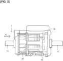
- Figure 2 shows an explanatory diagram of the drive unit 1.
- Figure 3 shows an explanatory diagram of the structure for mounting the drive unit 1 in the vehicle according to an embodiment of the present invention in a view in which the drive unit 1 and a suspension member 2 are seen from the underside of the vehicle 100.
- the drive unit 1 is configured such that the drive motor 10 and the gearbox 20 are connected in the width direction of the vehicle 100.
- the drive motor 10 is located on the right side
- the gearbox 20 is located on the left side
- the power converter 30 is arranged above the drive motor 10.
- the axles 71 extend outwardly in the width direction of the vehicle 100 from both ends of the drive motor 10 and the gearbox 20.
- the drive shaft of the drive motor 10 has a hollow structure, and one end of the drive shaft is connected to the input side of a speed reduction mechanism (speed change mechanism) 22 (see Figure 6 ) of the gearbox 20.
- the rotation which has been reduced by the speed reduction mechanism 22 is transmitted to the drive wheels 72 by the axle 71, which is connected to the output side of the speed reduction mechanism 22, passes through the hollow shaft to either side of the drive motor 10 and the gearbox 20.
- the drive unit 1 is supported by the suspension member 2 and mounted on the vehicle 100.
- the suspension member 2 includes a set of side members 81 that extend in the longitudinal direction of the vehicle 100 and a set of cross members 82 that extend in the widthwise direction of the vehicle 100.
- the set of side members 81 and the set of cross members 82 define an approximately rectangular form.
- the drive unit 1 is fixed to the side members 81 and the cross members 82 via a mount, such as bushings, so that the drive unit is located inside the rectangular shape of the suspension member 2.
- An exhaust pipe 51 extends from the engine 50.
- the exhaust pipe 51 extends form the engine 50 to a muffler 52 located on the rear side of the vehicle 100 and is positioned on the lower side of the vehicle 100.
- the exhaust pipe 51 is arranged to pass below the suspension member 2 (near side in Figure 3 ) along the longitudinal direction of the vehicle 100.
- the exhaust pipe 51 has a high surface temperature (e.g., 20 0° C) due to the high temperature of the exhaust gas discharged from the engine 50 that passes therethrough.
- the drive motor 10 and the power converter 30 should be located away from the exhaust pipe 51 since exposure to such high temperatures decreases efficiency.
- the suspension member 2 in addition to the drive unit 1, there are arranged the suspension member 2, the muffler 52, suspension elements, etc., not shown. Therefore, the placement of the exhaust pipe 51 at the rear of the vehicle 100 may be restricted, so that the distance between the drive unit 1 and the exhaust pipe 51 may prove insufficient.
- components such as insulators or blowers may be provided to prevent heat from the exhaust pipe 51 from being transmitted to the drive motor 10.
- components such as insulators or blowers may be provided to prevent heat from the exhaust pipe 51 from being transmitted to the drive motor 10.
- use of such a configuration would increase and assembly man-hours, resulting in higher costs.
- the present embodiment is configured so that, without increasing the parts count, heat from the exhaust pipe 51 is not transmitted to the drive motor 10.
- the exhaust pipe 51 extends from the engine 50 to the rear of the vehicle 100, and curves towards the left in Figure 3 (towards the side of the gearbox 20 side of the drive unit 1) near the suspension member 2.
- the exhaust pipe 51 curves toward the rear of the vehicle 100 near the intersection of the front cross member 82 and the left side member 81, and is arranged to follow the left side member 81, passing immediately below the left side member 81.
- the exhaust pipe 51 then passes the rear cross member 82.
- the exhaust pipe 51 extends below and runs along the front side member 81 and the left cross member 82 of the suspension member 2 adjacent to the lower part of the suspension member 2.
- Figure 4 shows an explanatory diagram of the drive unit 1 and the suspension member 2 as seen obliquely from the rear side of the vehicle 100 in the direction of arrow M of Figure 3 .
- the exhaust pipe 51 is configured to extend along the side member 81 and the cross member 82 beneath the suspension member 2. This arrangement of the exhaust pipe 51 near the suspension member 2 results in the side member 81 being interposed between the exhaust pipe 51 and the gearbox 20 in the vicinity of the drive unit 1.
- the suspension member 2 is made from a metal with high heat capacity, such as iron. Thus, the heat transferred from the exhaust pipe 51 to the suspension member 2 is diffused to the various parts of the suspension member 2 and is quickly dissipated by the travel wind.
- the drive motor 10 is located farther from the exhaust pipe 51 (left side of Figure 4 ) than the gearbox 20. That is, as seen from the drive motor 10, the gearbox 20 and the side member 81 are between the drive motor and the exhaust pipe 51.
- gearbox 20 includes a coolant flow channel 211, as will now be explained.
- Figure 5 shows an explanatory diagram of the gearbox 20 as seen from the axial direction (in the direction of arrow A of Figure 2 ).
- Figure 6 shows a cross section of the drive unit 1 and the suspension member 2 through VI-VI in Figure 3 .
- the gearbox 20 comprises a speed reduction mechanism 22 (see Figure 6 ) consisting of a plurality of gears (for example, a planetary gear mechanism) in a housing 21 that has an essentially cylindrical outer diameter.
- a speed reduction mechanism 22 (see Figure 6 ) consisting of a plurality of gears (for example, a planetary gear mechanism) in a housing 21 that has an essentially cylindrical outer diameter.
- the housing 21 is formed in a cylindrical shape from a metal, such as an aluminum alloy, and has the coolant flow channel 211 (indicated by the dotted line in Figure 5 ) through which a refrigerant (coolant) flows. If the housing 21 is cut along a plane perpendicular to the direction of the axis of rotation, the coolant flow channel 211 forms an arcuate space, opposite the lower part of the speed reduction mechanism 22, in the lower portion of the housing 21. This arcuate space forms a passage that extends in the longitudinal direction of the vehicle and is configured to cover the lower side of the speed reduction mechanism 22 (indicated by the single-dotted chain line in Figure 5 ) housed in the housing 21.
- a coolant inlet 212 and a coolant outlet 213 for allowing coolant to flow through the coolant flow channel 211 are provided on an end surface 21A (axial end on the opposite side of the drive motor 10) of the housing 21.
- the coolant inlet 212 and the coolant outlet 213 are arranged on the end surface 21A of the gearbox 20 at separate locations in the longitudinal direction of the vehicle 100.
- the coolant inlet 212 is disposed on the vehicle 100 rearward side of the gearbox 20 and is connected to one end of the arcuate coolant flow channel 211.
- the coolant outlet 213 is disposed on the vehicle 100 frontward side of the gearbox 20 and is connected to the other, upper end of the arcuate coolant flow channel 211.
- the coolant inlet 212 is positioned at a greater height from the road surface than the coolant outlet 213.
- Lubricating oil for lubricating the speed reduction mechanism 22 is stored inside the housing 21.
- the lubricating oil comes in contact with the coolant flow channel 211 formed in the housing 21 via the inner surface of the housing 21 and is cooled by the coolant in the coolant flow channel 211.
- the coolant flow channel 211 of the gearbox 20 is formed at a position facing the exhaust pipe 51, which is disposed near the bottom of the gearbox 20.
- the coolant inlet 212 is positioned at a greater height from the road surface than the coolant outlet 213.
- the coolant flow channel 211 which is arcuate at the bottom of the housing 21, is configured to cover the lubricating oil stored in the gearbox 20 from below.
- the cooling efficiency of the gearbox 20 on uphill roads can be increased. More specifically, when the vehicle 100 is on an uphill road, the surface of the lubricating oil inside the gearbox 20 (indicated by the single-dotted chain line in Figure 5 ) is tilted in accordance with the inclination of the uphill road, so that the oil level at the rear side of the vehicle is higher than that at the front side of the vehicle. Further, when the vehicle 100 travels over uphill roads, the torque required by the drive motor 10 or the engine 50 increases relative to travel on flat or downhill roads. Therefore, in such cases, the temperature of the exhaust pipe 51 increases.
- the cooling efficiency of the gearbox 20 is not impaired. Further, since the coolant of the coolant flow channel 211 quickly dissipates the heat transferred from the exhaust pipe 51, the heat from the exhaust pipe 51 is not transferred to the drive motor 10.
- the exhaust pipe 51 in the vicinity of the coolant inlet 212 located in the housing 21 of the gearbox 20 is configured such that, in a plan view, its center (center line P) is coincident with the widthwise center of the side member 81 (center line F) or outside (away from the gearbox 20) of the widthwise center.
- the heat from the exhaust pipe 51 is shielded by the side member 81 and is less likely to be transferred to the gearbox 20, especially to the coolant inlet 212.
- the coolant flowing in from the coolant inlet 212 is at a lower temperature than the coolant flowing out from the cooling water outlet 213 since it has not yet been subjected to heat exchange inside the gearbox 20.
- the embodiment of the present invention described above is applied to a structure for mounting the drive unit 1 comprising the drive motor 10 and the transmission (gearbox 20) in the vehicle 100 equipped with the engine 50.
- the drive unit 1 consists of the drive motor 10 and the gearbox 20 connected in series in the width direction of the vehicle 100.
- the exhaust pipe 51 of the engine 50 is extended so as to pass near the gearbox 20 in the longitudinal direction of the vehicle 100.
- the gearbox 20 is equipped with the coolant flow channel 211, through which flows the coolant for cooling the lubricating oil that lubricates the speed reduction mechanism 22 in the gearbox 20, and which is positioned opposite the exhaust pipe 51.
- the drive motor 10 and the power converter 30 also have housings, each of which is equipped with a coolant flow channel through which coolant flows.
- the gearbox 20 has the housing 21 that houses the speed reduction mechanism 22, the coolant flow channel 211 is formed in the housing 21, and the coolant flow channel 211 is formed below the housing 21 in an arcuate shape along the longitudinal direction of the vehicle.
- the coolant inlet 212 and the coolant outlet 213 of the coolant flow channel 211 are arranged in the housing 21 separated by a distance in the longitudinal direction of the vehicle 100, and one of the coolant inlet 212 and the coolant outlet 213 is positioned at a greater height from the ground than the other inlet or outlet.
- the coolant inlet 212 is located farther rearward of the vehicle 100 than the coolant outlet 213, and the coolant inlet 212 is located at a greater height from the ground than the coolant outlet 213.
- the power converter 30 that supplies electric power to the drive motor 10 is arranged above the drive motor 10.
- the drive unit 1 is supported by the suspension member 2.
- the suspension member 2 comprises the set of side members 81 that extend in the longitudinal direction of the vehicle 100 and the set of cross members 82 that extend in the widthwise direction of the vehicle 100, and the drive unit 1 is disposed within the approximately rectangular form defined by the set of side members 81 and the set of cross members 82.
- the exhaust pipe 51 is disposed along a side member 81 and below this side member 81.
- the exhaust pipe 51 is located near the coolant inlet 212 of the gearbox 20, on the lower side of the side member 81 and outside the center of the side member 81 in the width direction of the vehicle 100.
- the drive motor 10 of the present embodiment may be used as a source of drive power mounted in devices other than automobiles, such various electrical or industrial machines.
- the coolant inlet 212 is disposed on the vehicle 100 rearward side of the gearbox 20, but no limitation is implied thereby; the coolant outlet 213 may be arranged on the rearward side of the vehicle 100, and the coolant may be configured to flow from the vehicle front side of the gearbox 20 toward the rear side of the vehicle.
- the gearbox 20 may be configured as a transmission that has a speed change mechanism capable of switching between a plurality of reduction gears.
- the suspension member 2 (side member 81) is interposed between the exhaust pipe 51 and the gearbox 20, but no limitation is implied thereby. It is sufficient if only the gearbox 20 is interposed between the power converter 30 and the exhaust pipe 51 and the drive motor 10, without the suspension member 2.
- the coolant flow channel 211 of the gearbox 20 prevents the transfer of heat from the exhaust pipe 51 to the drive motor 10 and the power converter 30.
- the exhaust pipe 51 may be disposed in the vicinity of the side of the housing 21 with the coolant flow channel 211, rather than below the gearbox 20.
Landscapes
- Engineering & Computer Science (AREA)
- Mechanical Engineering (AREA)
- Transportation (AREA)
- Chemical & Material Sciences (AREA)
- Combustion & Propulsion (AREA)
- General Engineering & Computer Science (AREA)
- Power Engineering (AREA)
- Sustainable Development (AREA)
- Sustainable Energy (AREA)
- Life Sciences & Earth Sciences (AREA)
- Physics & Mathematics (AREA)
- Thermal Sciences (AREA)
- General Details Of Gearings (AREA)
- Hybrid Electric Vehicles (AREA)
Abstract
Description
- The present invention relates to an in-vehicle-mounted structure for mounting a drive unit in a vehicle equipped with an engine.
- In a hybrid vehicle equipped with an engine and a rotating electrical machine (motor), because of the vehicle layout, the exhaust pipe through which the engine exhaust gases pass may be positioned adjacent to the motor. In such an arrangement, the heat of the high-temperature exhaust pipe is transferred to the motor, which raises motor temperature and reduces motor efficiency.
-
JP2009-269547A - In the patent document described above, additional components, such as insulators and a blower, are installed in the vehicle to cool the motor, which increases the parts cost and the assembly man-hours.
- In light of these problems, the object of the present invention is to provide an in-vehicle-mounted structure for mounting a drive unit in a vehicle such that, without increasing costs, heat from the exhaust pipe is not transferred to the motor.
- An embodiment of the present invention is applied to an in-vehicle-mounted structure of a drive unit including a drive motor and a transmission in a vehicle equipped with an engine. The drive unit includes the drive motor and transmission connected in series in the width direction of the vehicle. An exhaust pipe of the engine is extended to pass adjacent to the transmission in the longitudinal direction of the vehicle. The transmission is equipped with a coolant flow channel, through which flows coolant for cooling lubricating oil that lubricates the speed change mechanism in the transmission, and which is positioned opposite the exhaust pipe.
- By means of the present invention, since the transmission is interposed between the drive motor and the exhaust pipe, and a coolant flow channel is provided in a position of the transmission opposite the exhaust pipe, the direct transfer of heat from the exhaust pipe to the motor is suppressed. Thus, an increase in the temperature of the drive motor can be suppressed without reducing drive motor efficiency or the addition of new components such as a blower.
-
-
Figure 1 is a cross-sectional diagram of a drive unit according to an embodiment of the present invention. -
Figure 2 is an explanatory diagram of the drive unit. -
Figure 3 is an explanatory diagram of an in-vehicle-mounted structure for mounting the drive unit in a vehicle. -
Figure 4 is an explanatory diagram of the in-vehicle-mounted structure for mounting the drive unit in the vehicle. -
Figure 5 is a side elevational view of a gearbox. -
Figure 6 is a cross-sectional diagram of the drive unit. - Embodiments of the present invention will be described below with reference to the drawings, etc.
-
Figure 1 shows a block diagram of ahybrid vehicle 100 equipped with adrive unit 1 according to an embodiment of the present invention. - The hybrid vehicle (hereinafter also referred to as the "vehicle") 100 is equipped with the
drive unit 1, abattery 40, anengine 50, agenerator 60,axles 71 and a pair ofdrive wheels 72. Thedrive unit 1 is equipped with a drive motor (rotating electric machine) 10, a gearbox (transmission) 20 and apower converter 30. - The
drive motor 10 is driven by receiving the electric power supply from thepower converter 30 and drives thevehicle 100 by rotating thedrive wheels 72. Thedrive motor 10 also functions as a generator that generates regenerative power during the deceleration of thevehicle 100. - The
gearbox 20 is a transmission device having a plurality of gears that reduces the speed of the rotation of thedrive motor 10 and causes thedrive wheels 72 to rotate via theaxles 71. Thegearbox 20 is arranged in series with thedrive motor 10 and rotates theaxles 71 through thegearbox 20 and thedrive motor 10. - The
power converter 30 is configured with an inverter unit, converts the electric power stored in thebattery 40 into electric power suitable for driving thedrive motor 10, and supplies the electric power to thedrive motor 10. Thepower converter 30 receives the electric power generated by thegenerator 60 or the regenerated power of thedrive motor 10 and charges thebattery 40. - When the SOC of the
battery 40 decreases, thepower converter 30 starts theengine 50, and theengine 50 drives thegenerator 60 to generate power. The electric power generated by thegenerator 60 is supplied to thedrive motor 10 via thepower converter 30 or is used to charge thebattery 40. - The
vehicle 100 of the present embodiment is equipped with thedrive unit 1 on the rear side of thevehicle 100 to drive thedrive wheels 72, which are the rear wheels. A separate motor that drives the front wheels may be provided on the front side of the vehicle 100 (for example, in the engine compartment), or theengine 50 can be configured to drive the front wheels. -
Figure 2 shows an explanatory diagram of thedrive unit 1.Figure 3 shows an explanatory diagram of the structure for mounting thedrive unit 1 in the vehicle according to an embodiment of the present invention in a view in which thedrive unit 1 and asuspension member 2 are seen from the underside of thevehicle 100. - As shown in
Figure 2 , thedrive unit 1 is configured such that thedrive motor 10 and thegearbox 20 are connected in the width direction of thevehicle 100. InFigure 2 , thedrive motor 10 is located on the right side, thegearbox 20 is located on the left side, and thepower converter 30 is arranged above thedrive motor 10. Theaxles 71 extend outwardly in the width direction of thevehicle 100 from both ends of thedrive motor 10 and thegearbox 20. - The drive shaft of the
drive motor 10 has a hollow structure, and one end of the drive shaft is connected to the input side of a speed reduction mechanism (speed change mechanism) 22 (seeFigure 6 ) of thegearbox 20. The rotation which has been reduced by thespeed reduction mechanism 22 is transmitted to thedrive wheels 72 by theaxle 71, which is connected to the output side of thespeed reduction mechanism 22, passes through the hollow shaft to either side of thedrive motor 10 and thegearbox 20. - As shown in
Figure 3 , thedrive unit 1 is supported by thesuspension member 2 and mounted on thevehicle 100. - The
suspension member 2 includes a set ofside members 81 that extend in the longitudinal direction of thevehicle 100 and a set ofcross members 82 that extend in the widthwise direction of thevehicle 100. The set ofside members 81 and the set ofcross members 82 define an approximately rectangular form. Thedrive unit 1 is fixed to theside members 81 and thecross members 82 via a mount, such as bushings, so that the drive unit is located inside the rectangular shape of thesuspension member 2. - An
exhaust pipe 51 extends from theengine 50. Theexhaust pipe 51 extends form theengine 50 to amuffler 52 located on the rear side of thevehicle 100 and is positioned on the lower side of thevehicle 100. - Close to the
suspension member 2, theexhaust pipe 51 is arranged to pass below the suspension member 2 (near side inFigure 3 ) along the longitudinal direction of thevehicle 100. - Here, in the prior art, when the
drive unit 1 was arranged in the rear section of thevehicle 100, there were the following problems. - The
exhaust pipe 51 has a high surface temperature (e.g., 20 0° C) due to the high temperature of the exhaust gas discharged from theengine 50 that passes therethrough. On the other hand, thedrive motor 10 and thepower converter 30 should be located away from theexhaust pipe 51 since exposure to such high temperatures decreases efficiency. - However, in the rear area of the
vehicle 100, where thesuspension member 2 is located, in addition to thedrive unit 1, there are arranged thesuspension member 2, themuffler 52, suspension elements, etc., not shown. Therefore, the placement of theexhaust pipe 51 at the rear of thevehicle 100 may be restricted, so that the distance between thedrive unit 1 and theexhaust pipe 51 may prove insufficient. - In this case, components such as insulators or blowers may be provided to prevent heat from the
exhaust pipe 51 from being transmitted to thedrive motor 10. However, use of such a configuration would increase and assembly man-hours, resulting in higher costs. - Thus, as described below, the present embodiment is configured so that, without increasing the parts count, heat from the
exhaust pipe 51 is not transmitted to thedrive motor 10. - As shown in
Figure 3 , theexhaust pipe 51 extends from theengine 50 to the rear of thevehicle 100, and curves towards the left inFigure 3 (towards the side of thegearbox 20 side of the drive unit 1) near thesuspension member 2. Theexhaust pipe 51 curves toward the rear of thevehicle 100 near the intersection of thefront cross member 82 and theleft side member 81, and is arranged to follow theleft side member 81, passing immediately below theleft side member 81. Theexhaust pipe 51 then passes therear cross member 82. - In this way, the
exhaust pipe 51 extends below and runs along thefront side member 81 and theleft cross member 82 of thesuspension member 2 adjacent to the lower part of thesuspension member 2. -
Figure 4 shows an explanatory diagram of thedrive unit 1 and thesuspension member 2 as seen obliquely from the rear side of thevehicle 100 in the direction of arrow M ofFigure 3 . - As shown in
Figure 4 , theexhaust pipe 51 is configured to extend along theside member 81 and thecross member 82 beneath thesuspension member 2. This arrangement of theexhaust pipe 51 near thesuspension member 2 results in theside member 81 being interposed between theexhaust pipe 51 and thegearbox 20 in the vicinity of thedrive unit 1. - The
suspension member 2 is made from a metal with high heat capacity, such as iron. Thus, the heat transferred from theexhaust pipe 51 to thesuspension member 2 is diffused to the various parts of thesuspension member 2 and is quickly dissipated by the travel wind. - With this configuration, heat from the
exhaust pipe 51 is shielded by theside member 81 and is less likely to be transferred to thedrive unit 1 side. - In the
drive unit 1, thedrive motor 10 is located farther from the exhaust pipe 51 (left side ofFigure 4 ) than thegearbox 20. That is, as seen from thedrive motor 10, thegearbox 20 and theside member 81 are between the drive motor and theexhaust pipe 51. - With this configuration, the heat from the
exhaust pipe 51 is shielded by theside members 81 and thegearbox 20 and is prevented from being directly transferred to thedrive motor 10 and thepower converter 30. - Further, the
gearbox 20 includes acoolant flow channel 211, as will now be explained. -
Figure 5 shows an explanatory diagram of thegearbox 20 as seen from the axial direction (in the direction of arrow A ofFigure 2 ).Figure 6 shows a cross section of thedrive unit 1 and thesuspension member 2 through VI-VI inFigure 3 . - The
gearbox 20 comprises a speed reduction mechanism 22 (seeFigure 6 ) consisting of a plurality of gears (for example, a planetary gear mechanism) in ahousing 21 that has an essentially cylindrical outer diameter. - The
housing 21 is formed in a cylindrical shape from a metal, such as an aluminum alloy, and has the coolant flow channel 211 (indicated by the dotted line inFigure 5 ) through which a refrigerant (coolant) flows. If thehousing 21 is cut along a plane perpendicular to the direction of the axis of rotation, thecoolant flow channel 211 forms an arcuate space, opposite the lower part of thespeed reduction mechanism 22, in the lower portion of thehousing 21. This arcuate space forms a passage that extends in the longitudinal direction of the vehicle and is configured to cover the lower side of the speed reduction mechanism 22 (indicated by the single-dotted chain line inFigure 5 ) housed in thehousing 21. - A
coolant inlet 212 and acoolant outlet 213 for allowing coolant to flow through thecoolant flow channel 211 are provided on anend surface 21A (axial end on the opposite side of the drive motor 10) of thehousing 21. Thecoolant inlet 212 and thecoolant outlet 213 are arranged on theend surface 21A of thegearbox 20 at separate locations in the longitudinal direction of thevehicle 100. - That is, the
coolant inlet 212 is disposed on thevehicle 100 rearward side of thegearbox 20 and is connected to one end of the arcuatecoolant flow channel 211. Thecoolant outlet 213 is disposed on thevehicle 100 frontward side of thegearbox 20 and is connected to the other, upper end of the arcuatecoolant flow channel 211. Thecoolant inlet 212 is positioned at a greater height from the road surface than thecoolant outlet 213. - Lubricating oil for lubricating the
speed reduction mechanism 22 is stored inside thehousing 21. The lubricating oil comes in contact with thecoolant flow channel 211 formed in thehousing 21 via the inner surface of thehousing 21 and is cooled by the coolant in thecoolant flow channel 211. - As shown in
Figure 6 , thecoolant flow channel 211 of thegearbox 20 is formed at a position facing theexhaust pipe 51, which is disposed near the bottom of thegearbox 20. - Although some of the heat from the
exhaust pipe 51 passes through theside member 81 and is transferred to the lower portion of theend surface 21A side of thehousing 21 of thegearbox 20, the heat transferred to thehousing 21 is suppressed from being transferred to thedrive motor 10 and thepower converter 30 due to the presence of thecoolant flow channel 211 in thehousing 21. - In the present embodiment, there are locations between the
exhaust pipe 51 and thegearbox 20 where the suspension member 2 (side members 81, cross member 82) does not necessarily exist. Even in such locations, the interposition of thecoolant flow channel 211 of thegearbox 20 prevents the transfer of heat from theexhaust pipe 51 to thedrive motor 10. - Also, in the
gearbox 20, thecoolant inlet 212 is positioned at a greater height from the road surface than thecoolant outlet 213. Thecoolant flow channel 211, which is arcuate at the bottom of thehousing 21, is configured to cover the lubricating oil stored in thegearbox 20 from below. - With this configuration, the cooling efficiency of the
gearbox 20 on uphill roads can be increased. More specifically, when thevehicle 100 is on an uphill road, the surface of the lubricating oil inside the gearbox 20 (indicated by the single-dotted chain line inFigure 5 ) is tilted in accordance with the inclination of the uphill road, so that the oil level at the rear side of the vehicle is higher than that at the front side of the vehicle. Further, when thevehicle 100 travels over uphill roads, the torque required by thedrive motor 10 or theengine 50 increases relative to travel on flat or downhill roads. Therefore, in such cases, the temperature of theexhaust pipe 51 increases. - As shown in
Figure 5 , since the rear side of the vehicle of the coolant flow channel 211 (coolant inlet 212) is in a higher position, even if the oil level of the lubricating oil is tilted rearward, thecoolant inlet 212 is positioned above the tilted lubricating oil level. Thus, almost all of the stored lubricating oil is cooled by the coolant. - Therefore, even when the
vehicle 100 travels over an uphill road, the cooling efficiency of thegearbox 20 is not impaired. Further, since the coolant of thecoolant flow channel 211 quickly dissipates the heat transferred from theexhaust pipe 51, the heat from theexhaust pipe 51 is not transferred to thedrive motor 10. - Further, as shown in
Figure 3 , theexhaust pipe 51 in the vicinity of thecoolant inlet 212 located in thehousing 21 of thegearbox 20 is configured such that, in a plan view, its center (center line P) is coincident with the widthwise center of the side member 81 (center line F) or outside (away from the gearbox 20) of the widthwise center. - The heat from the
exhaust pipe 51 is shielded by theside member 81 and is less likely to be transferred to thegearbox 20, especially to thecoolant inlet 212. The coolant flowing in from thecoolant inlet 212 is at a lower temperature than the coolant flowing out from the coolingwater outlet 213 since it has not yet been subjected to heat exchange inside thegearbox 20. Thus, by means of a configuration in which there is no heat transfer from theexhaust pipe 51 near thecoolant inlet 212, the cooling efficiency of thegearbox 20 can be prevented from being impaired. - The embodiment of the present invention described above is applied to a structure for mounting the
drive unit 1 comprising thedrive motor 10 and the transmission (gearbox 20) in thevehicle 100 equipped with theengine 50. Thedrive unit 1 consists of thedrive motor 10 and thegearbox 20 connected in series in the width direction of thevehicle 100. Theexhaust pipe 51 of theengine 50 is extended so as to pass near thegearbox 20 in the longitudinal direction of thevehicle 100. Thegearbox 20 is equipped with thecoolant flow channel 211, through which flows the coolant for cooling the lubricating oil that lubricates thespeed reduction mechanism 22 in thegearbox 20, and which is positioned opposite theexhaust pipe 51. - With this configuration, the heat from the
exhaust pipe 51 is not directly transferred to thedrive motor 10, and the heat that is transferred to thegearbox 20 is quickly removed by the coolant. As a result, since thedrive motor 10 is unaffected by the heat from theexhaust pipe 51, it is possible to prevent a reduction in the efficiency of thedrive motor 10 without the addition of new parts, such as heat shields. Thedrive motor 10 and thepower converter 30 also have housings, each of which is equipped with a coolant flow channel through which coolant flows. - In addition, in the present embodiment, the
gearbox 20 has thehousing 21 that houses thespeed reduction mechanism 22, thecoolant flow channel 211 is formed in thehousing 21, and thecoolant flow channel 211 is formed below thehousing 21 in an arcuate shape along the longitudinal direction of the vehicle. - With this configuration, the cooling efficiency of the
gearbox 20 is not impaired since the lubricating oil is continuously cooled by the coolant on the inner circumferential side of the arcuatecoolant flow channel 211. - Moreover, in the present embodiment, the
coolant inlet 212 and thecoolant outlet 213 of thecoolant flow channel 211 are arranged in thehousing 21 separated by a distance in the longitudinal direction of thevehicle 100, and one of thecoolant inlet 212 and thecoolant outlet 213 is positioned at a greater height from the ground than the other inlet or outlet. - With this configuration, even if the oil level of the lubricating oil tilts inside the
gearbox 20 when thevehicle 100 travels over an uphill road, the cooling efficiency of thegearbox 20 is not impaired since the coolant flows above the tilted lubricating oil level. - Also, in the present embodiment, the
coolant inlet 212 is located farther rearward of thevehicle 100 than thecoolant outlet 213, and thecoolant inlet 212 is located at a greater height from the ground than thecoolant outlet 213. - With this configuration, when the
vehicle 100 travels over an uphill road, even if the oil level of the lubricating oil tilts rearward inside thegearbox 20, the coolant circulates due to the presence of thecoolant inlet 212 above the tilted lubricating oil surface, so that, even during travel on uphill roads, the cooling efficiency of thegearbox 20 is not impaired. - Further, in the present embodiment, in the
drive unit 1, thepower converter 30 that supplies electric power to thedrive motor 10 is arranged above thedrive motor 10. - With this configuration, the heat from the
exhaust pipe 51 is not directly transferred to thepower converter 30, and thepower converter 30 is unaffected by the heat from theexhaust pipe 51, so that it is possible to prevent a reduction in the efficiency of thepower converter 30 without the need for additional components. - In the present embodiment, the
drive unit 1 is supported by thesuspension member 2. Thesuspension member 2 comprises the set ofside members 81 that extend in the longitudinal direction of thevehicle 100 and the set ofcross members 82 that extend in the widthwise direction of thevehicle 100, and thedrive unit 1 is disposed within the approximately rectangular form defined by the set ofside members 81 and the set ofcross members 82. Theexhaust pipe 51 is disposed along aside member 81 and below thisside member 81. - With this configuration, the heat from the
exhaust pipe 51 is shielded by theside members 81 and is less likely to be transferred to thedrive unit 1 side; thus, a reduction in the efficiency of thedrive motor 10 can be prevented without the need for additional parts. - Further, in the present embodiment, the
exhaust pipe 51 is located near thecoolant inlet 212 of thegearbox 20, on the lower side of theside member 81 and outside the center of theside member 81 in the width direction of thevehicle 100. - With this configuration, the cooling efficiency of the
gearbox 20 is not impaired since the heat from theexhaust pipe 51 is shielded by theside member 81 at thecoolant inlet 212 from which the coolant with the lowest temperature flows into thegearbox 20. - Embodiments of the present invention and modified examples thereof were described above, but the above-described embodiments and modified examples illustrate only some of the application examples of the present invention and are not intended to limit the technical scope of the present invention to the specific configurations of the above-described embodiments.
- The
drive motor 10 of the present embodiment may be used as a source of drive power mounted in devices other than automobiles, such various electrical or industrial machines. - Further, in the present embodiment, the
coolant inlet 212 is disposed on thevehicle 100 rearward side of thegearbox 20, but no limitation is implied thereby; thecoolant outlet 213 may be arranged on the rearward side of thevehicle 100, and the coolant may be configured to flow from the vehicle front side of thegearbox 20 toward the rear side of the vehicle. - Further, in the present embodiment, the
gearbox 20 may be configured as a transmission that has a speed change mechanism capable of switching between a plurality of reduction gears. - Further, in the present embodiment, the suspension member 2 (side member 81) is interposed between the
exhaust pipe 51 and thegearbox 20, but no limitation is implied thereby. It is sufficient if only thegearbox 20 is interposed between thepower converter 30 and theexhaust pipe 51 and thedrive motor 10, without thesuspension member 2. Thecoolant flow channel 211 of thegearbox 20 prevents the transfer of heat from theexhaust pipe 51 to thedrive motor 10 and thepower converter 30. In this case, theexhaust pipe 51 may be disposed in the vicinity of the side of thehousing 21 with thecoolant flow channel 211, rather than below thegearbox 20.
Claims (7)
- An in-vehicle-mounted structure of a drive unit including a drive motor and a transmission is mounted to a vehicle equipped with an engine, comprising:the drive unit including a drive motor and a transmission to be mounted to a vehicle equipped with an engine, the drive motor and the transmission being connected in series in a widthwise direction of the vehicle; andan exhaust pipe of the engine extending adjacent to the transmission in a longitudinal direction of the vehicle,the transmission including a coolant flow channel through which flows coolant for cooling lubricating oil that lubricates a speed change mechanism inside the transmission, and the coolant flow channel being positioned to face the exhaust pipe.
- The in-vehicle mounted structure of the drive unit according to claim 1, whereinthe transmission includes a housing that houses the speed change mechanism,the coolant flow channel is formed in the housing, andthe coolant flow channel is formed below the housing in an arcuate shape to face a lower portion of the speed change mechanism.
- The in-vehicle mounted structure of the drive unit according to claim 2, whereina coolant inlet and a coolant outlet of the coolant flow channel are arranged in the housing separated by a distance in the longitudinal direction of the vehicle, andone of the coolant inlet and the coolant outlet is positioned at a greater height from a road surface than of the coolant inlet and the coolant outlet.
- The in-vehicle mounted structure of the drive unit according to claim 3, whereinthe coolant inlet is arranged farther rearward of the vehicle than the coolant outlet, andthe coolant inlet is arranged at a greater height from the road surface than the coolant outlet.
- The in-vehicle mounted structure of the drive unit according to any one of claims 1 to 4, wherein
the drive unit includes a power converter that supplies electric power to the drive motor, and that is disposed above the drive motor. - The in-vehicle mounted structure of the drive unit according to any one of claims 1 to 5, whereinthe drive unit is supported by a suspension member,the suspension member includes a set of side members extending in the longitudinal direction of the vehicle and a set of cross members extending in the widthwise direction of the vehicle,the drive unit is disposed within an approximately rectangular form defined by the set of side members and the set of cross members, andthe exhaust pipe is disposed along and below the side member.
- The in-vehicle mounted structure of the drive unit according to claim 6, wherein
1 the exhaust pipe is disposed near the coolant inlet of the transmission, below the side members, and farther outside from a center of the side members in the widthwise direction of the vehicle.
Applications Claiming Priority (1)
| Application Number | Priority Date | Filing Date | Title |
|---|---|---|---|
| PCT/JP2021/025507 WO2023281633A1 (en) | 2021-07-06 | 2021-07-06 | Vehicle-mounted structure for driving unit |
Publications (3)
| Publication Number | Publication Date |
|---|---|
| EP4368432A1 true EP4368432A1 (en) | 2024-05-15 |
| EP4368432A4 EP4368432A4 (en) | 2024-08-28 |
| EP4368432B1 EP4368432B1 (en) | 2025-11-26 |
Family
ID=84800502
Family Applications (1)
| Application Number | Title | Priority Date | Filing Date |
|---|---|---|---|
| EP21949269.1A Active EP4368432B1 (en) | 2021-07-06 | 2021-07-06 | Vehicle-mounted structure for driving unit |
Country Status (5)
| Country | Link |
|---|---|
| US (1) | US12447795B2 (en) |
| EP (1) | EP4368432B1 (en) |
| JP (1) | JP7616386B2 (en) |
| CN (1) | CN117642304A (en) |
| WO (1) | WO2023281633A1 (en) |
Family Cites Families (13)
| Publication number | Priority date | Publication date | Assignee | Title |
|---|---|---|---|---|
| JP2008044406A (en) * | 2006-08-10 | 2008-02-28 | Fuji Heavy Ind Ltd | Hybrid vehicle motor cooling device |
| JP4069950B2 (en) * | 2006-09-20 | 2008-04-02 | トヨタ自動車株式会社 | Vehicle drive device and vehicle |
| JP2009269547A (en) | 2008-05-09 | 2009-11-19 | Mazda Motor Corp | Hybrid vehicle |
| JP5446921B2 (en) * | 2010-01-22 | 2014-03-19 | マツダ株式会社 | Electric vehicle structure |
| JP5821273B2 (en) * | 2011-05-19 | 2015-11-24 | いすゞ自動車株式会社 | Gear device and vehicle equipped with the same |
| US9266423B2 (en) * | 2011-06-07 | 2016-02-23 | Honda Motor Co., Ltd. | Vehicle driving device |
| CN104334386B (en) * | 2012-05-23 | 2016-04-27 | 本田技研工业株式会社 | Motor vehicle driven by mixed power |
| JP6327174B2 (en) * | 2015-02-20 | 2018-05-23 | 株式会社安川電機 | Drive device |
| US10094464B2 (en) * | 2016-08-04 | 2018-10-09 | GM Global Technology Operations LLC | Thermoelectric generator for transmission warm-up |
| JP2018058501A (en) * | 2016-10-06 | 2018-04-12 | 愛知機械工業株式会社 | Power output device |
| US10300785B2 (en) * | 2017-09-25 | 2019-05-28 | GM Global Technology Operations LLC | Cooling by suction of air |
| JP2019116128A (en) | 2017-12-26 | 2019-07-18 | 本田技研工業株式会社 | Vehicle cooling cycle |
| JP6724091B2 (en) * | 2018-09-06 | 2020-07-15 | 本田技研工業株式会社 | Hybrid vehicle |
-
2021
- 2021-07-06 WO PCT/JP2021/025507 patent/WO2023281633A1/en not_active Ceased
- 2021-07-06 CN CN202180100080.6A patent/CN117642304A/en active Pending
- 2021-07-06 JP JP2023532927A patent/JP7616386B2/en active Active
- 2021-07-06 US US18/575,480 patent/US12447795B2/en active Active
- 2021-07-06 EP EP21949269.1A patent/EP4368432B1/en active Active
Also Published As
| Publication number | Publication date |
|---|---|
| JP7616386B2 (en) | 2025-01-17 |
| US20240300287A1 (en) | 2024-09-12 |
| EP4368432A4 (en) | 2024-08-28 |
| EP4368432B1 (en) | 2025-11-26 |
| WO2023281633A1 (en) | 2023-01-12 |
| CN117642304A (en) | 2024-03-01 |
| JPWO2023281633A1 (en) | 2023-01-12 |
| US12447795B2 (en) | 2025-10-21 |
Similar Documents
| Publication | Publication Date | Title |
|---|---|---|
| EP2799319B1 (en) | Saddle-type electric vehicle | |
| JP5891309B2 (en) | Electric vehicle | |
| CN107921854A (en) | Electric automobile | |
| JP5585667B2 (en) | Cooling system | |
| EP2247460B1 (en) | Hybrid vehicle powertrain | |
| US20240343107A1 (en) | Power transmission device | |
| KR20230084794A (en) | Power transmission device | |
| EP2225119B1 (en) | Hybrid vehicle powertrain | |
| US12540666B2 (en) | Electrically operable axle drive train | |
| EP4368432B1 (en) | Vehicle-mounted structure for driving unit | |
| JP6390547B2 (en) | Vehicle drive device | |
| JP2009132252A (en) | In-wheel motor for vehicles | |
| US10766354B2 (en) | Vehicle having cooling arrangement disposed below floor surface | |
| KR20140075981A (en) | Cooling unit inner shaft bearing part in hollow type motor | |
| JP2020006773A (en) | Electric drive type travel device and electric drive type work vehicle | |
| JP2022052843A (en) | Vehicular cooling structure | |
| WO2024055631A1 (en) | Electric drive transmission system and vehicle | |
| JP5321405B2 (en) | Cooling device for left and right independent drive vehicle | |
| JP3649104B2 (en) | Parallel hybrid electric truck | |
| JP3551461B2 (en) | Outside air introduction structure for vehicles | |
| CN115003532B (en) | Powertrain for vehicle | |
| KR20260001491A (en) | Hybrid electric vehicle | |
| JPH07123645A (en) | Vehicle electric motor cooling structure | |
| JP2026028493A (en) | heat exchange equipment | |
| WO2023053588A1 (en) | Electric power unit |
Legal Events
| Date | Code | Title | Description |
|---|---|---|---|
| STAA | Information on the status of an ep patent application or granted ep patent |
Free format text: STATUS: THE INTERNATIONAL PUBLICATION HAS BEEN MADE |
|
| PUAI | Public reference made under article 153(3) epc to a published international application that has entered the european phase |
Free format text: ORIGINAL CODE: 0009012 |
|
| STAA | Information on the status of an ep patent application or granted ep patent |
Free format text: STATUS: REQUEST FOR EXAMINATION WAS MADE |
|
| 17P | Request for examination filed |
Effective date: 20240131 |
|
| AK | Designated contracting states |
Kind code of ref document: A1 Designated state(s): AL AT BE BG CH CY CZ DE DK EE ES FI FR GB GR HR HU IE IS IT LI LT LU LV MC MK MT NL NO PL PT RO RS SE SI SK SM TR |
|
| A4 | Supplementary search report drawn up and despatched |
Effective date: 20240725 |
|
| RIC1 | Information provided on ipc code assigned before grant |
Ipc: B60L 50/16 20190101ALI20240719BHEP Ipc: B60K 6/54 20071001AFI20240719BHEP |
|
| DAV | Request for validation of the european patent (deleted) | ||
| DAX | Request for extension of the european patent (deleted) | ||
| GRAP | Despatch of communication of intention to grant a patent |
Free format text: ORIGINAL CODE: EPIDOSNIGR1 |
|
| STAA | Information on the status of an ep patent application or granted ep patent |
Free format text: STATUS: GRANT OF PATENT IS INTENDED |
|
| INTG | Intention to grant announced |
Effective date: 20250710 |
|
| GRAS | Grant fee paid |
Free format text: ORIGINAL CODE: EPIDOSNIGR3 |
|
| GRAA | (expected) grant |
Free format text: ORIGINAL CODE: 0009210 |
|
| STAA | Information on the status of an ep patent application or granted ep patent |
Free format text: STATUS: THE PATENT HAS BEEN GRANTED |
|
| AK | Designated contracting states |
Kind code of ref document: B1 Designated state(s): AL AT BE BG CH CY CZ DE DK EE ES FI FR GB GR HR HU IE IS IT LI LT LU LV MC MK MT NL NO PL PT RO RS SE SI SK SM TR |
|
| REG | Reference to a national code |
Ref country code: CH Ref legal event code: F10 Free format text: ST27 STATUS EVENT CODE: U-0-0-F10-F00 (AS PROVIDED BY THE NATIONAL OFFICE) Effective date: 20251126 Ref country code: GB Ref legal event code: FG4D |
|
| REG | Reference to a national code |
Ref country code: DE Ref legal event code: R096 Ref document number: 602021043402 Country of ref document: DE |
|
| REG | Reference to a national code |
Ref country code: IE Ref legal event code: FG4D |
|
| REG | Reference to a national code |
Ref country code: NL Ref legal event code: MP Effective date: 20251126 |
|
| PG25 | Lapsed in a contracting state [announced via postgrant information from national office to epo] |
Ref country code: ES Free format text: LAPSE BECAUSE OF FAILURE TO SUBMIT A TRANSLATION OF THE DESCRIPTION OR TO PAY THE FEE WITHIN THE PRESCRIBED TIME-LIMIT Effective date: 20251126 |
|
| REG | Reference to a national code |
Ref country code: LT Ref legal event code: MG9D |
|
| PG25 | Lapsed in a contracting state [announced via postgrant information from national office to epo] |
Ref country code: NO Free format text: LAPSE BECAUSE OF FAILURE TO SUBMIT A TRANSLATION OF THE DESCRIPTION OR TO PAY THE FEE WITHIN THE PRESCRIBED TIME-LIMIT Effective date: 20260226 |
|
| PG25 | Lapsed in a contracting state [announced via postgrant information from national office to epo] |
Ref country code: AT Free format text: LAPSE BECAUSE OF FAILURE TO SUBMIT A TRANSLATION OF THE DESCRIPTION OR TO PAY THE FEE WITHIN THE PRESCRIBED TIME-LIMIT Effective date: 20251126 Ref country code: HR Free format text: LAPSE BECAUSE OF FAILURE TO SUBMIT A TRANSLATION OF THE DESCRIPTION OR TO PAY THE FEE WITHIN THE PRESCRIBED TIME-LIMIT Effective date: 20251126 Ref country code: FI Free format text: LAPSE BECAUSE OF FAILURE TO SUBMIT A TRANSLATION OF THE DESCRIPTION OR TO PAY THE FEE WITHIN THE PRESCRIBED TIME-LIMIT Effective date: 20251126 |
|
| REG | Reference to a national code |
Ref country code: AT Ref legal event code: MK05 Ref document number: 1860757 Country of ref document: AT Kind code of ref document: T Effective date: 20251126 |
|
| PG25 | Lapsed in a contracting state [announced via postgrant information from national office to epo] |
Ref country code: NL Free format text: LAPSE BECAUSE OF FAILURE TO SUBMIT A TRANSLATION OF THE DESCRIPTION OR TO PAY THE FEE WITHIN THE PRESCRIBED TIME-LIMIT Effective date: 20251126 |
|
| PG25 | Lapsed in a contracting state [announced via postgrant information from national office to epo] |
Ref country code: RS Free format text: LAPSE BECAUSE OF FAILURE TO SUBMIT A TRANSLATION OF THE DESCRIPTION OR TO PAY THE FEE WITHIN THE PRESCRIBED TIME-LIMIT Effective date: 20260226 |
|
| PG25 | Lapsed in a contracting state [announced via postgrant information from national office to epo] |
Ref country code: IS Free format text: LAPSE BECAUSE OF FAILURE TO SUBMIT A TRANSLATION OF THE DESCRIPTION OR TO PAY THE FEE WITHIN THE PRESCRIBED TIME-LIMIT Effective date: 20260326 |
|
| PG25 | Lapsed in a contracting state [announced via postgrant information from national office to epo] |
Ref country code: PT Free format text: LAPSE BECAUSE OF FAILURE TO SUBMIT A TRANSLATION OF THE DESCRIPTION OR TO PAY THE FEE WITHIN THE PRESCRIBED TIME-LIMIT Effective date: 20260326 |
|
| PG25 | Lapsed in a contracting state [announced via postgrant information from national office to epo] |
Ref country code: PL Free format text: LAPSE BECAUSE OF FAILURE TO SUBMIT A TRANSLATION OF THE DESCRIPTION OR TO PAY THE FEE WITHIN THE PRESCRIBED TIME-LIMIT Effective date: 20251126 |
|
| PG25 | Lapsed in a contracting state [announced via postgrant information from national office to epo] |
Ref country code: LV Free format text: LAPSE BECAUSE OF FAILURE TO SUBMIT A TRANSLATION OF THE DESCRIPTION OR TO PAY THE FEE WITHIN THE PRESCRIBED TIME-LIMIT Effective date: 20251126 |
|
| PG25 | Lapsed in a contracting state [announced via postgrant information from national office to epo] |
Ref country code: BG Free format text: LAPSE BECAUSE OF FAILURE TO SUBMIT A TRANSLATION OF THE DESCRIPTION OR TO PAY THE FEE WITHIN THE PRESCRIBED TIME-LIMIT Effective date: 20251126 |