EP4368431A1 - Work vehicle - Google Patents
Work vehicle Download PDFInfo
- Publication number
- EP4368431A1 EP4368431A1 EP23208922.7A EP23208922A EP4368431A1 EP 4368431 A1 EP4368431 A1 EP 4368431A1 EP 23208922 A EP23208922 A EP 23208922A EP 4368431 A1 EP4368431 A1 EP 4368431A1
- Authority
- EP
- European Patent Office
- Prior art keywords
- battery
- support section
- frame member
- work vehicle
- section
- Prior art date
- Legal status (The legal status is an assumption and is not a legal conclusion. Google has not performed a legal analysis and makes no representation as to the accuracy of the status listed.)
- Pending
Links
Images


Classifications
-
- B—PERFORMING OPERATIONS; TRANSPORTING
- B60—VEHICLES IN GENERAL
- B60L—PROPULSION OF ELECTRICALLY-PROPELLED VEHICLES; SUPPLYING ELECTRIC POWER FOR AUXILIARY EQUIPMENT OF ELECTRICALLY-PROPELLED VEHICLES; ELECTRODYNAMIC BRAKE SYSTEMS FOR VEHICLES IN GENERAL; MAGNETIC SUSPENSION OR LEVITATION FOR VEHICLES; MONITORING OPERATING VARIABLES OF ELECTRICALLY-PROPELLED VEHICLES; ELECTRIC SAFETY DEVICES FOR ELECTRICALLY-PROPELLED VEHICLES
- B60L50/00—Electric propulsion with power supplied within the vehicle
- B60L50/50—Electric propulsion with power supplied within the vehicle using propulsion power supplied by batteries or fuel cells
- B60L50/60—Electric propulsion with power supplied within the vehicle using propulsion power supplied by batteries or fuel cells using power supplied by batteries
- B60L50/66—Arrangements of batteries
-
- B—PERFORMING OPERATIONS; TRANSPORTING
- B60—VEHICLES IN GENERAL
- B60K—ARRANGEMENT OR MOUNTING OF PROPULSION UNITS OR OF TRANSMISSIONS IN VEHICLES; ARRANGEMENT OR MOUNTING OF PLURAL DIVERSE PRIME-MOVERS IN VEHICLES; AUXILIARY DRIVES FOR VEHICLES; INSTRUMENTATION OR DASHBOARDS FOR VEHICLES; ARRANGEMENTS IN CONNECTION WITH COOLING, AIR INTAKE, GAS EXHAUST OR FUEL SUPPLY OF PROPULSION UNITS IN VEHICLES
- B60K1/00—Arrangement or mounting of electrical propulsion units
- B60K1/04—Arrangement or mounting of electrical propulsion units of the electric storage means for propulsion
-
- B—PERFORMING OPERATIONS; TRANSPORTING
- B60—VEHICLES IN GENERAL
- B60K—ARRANGEMENT OR MOUNTING OF PROPULSION UNITS OR OF TRANSMISSIONS IN VEHICLES; ARRANGEMENT OR MOUNTING OF PLURAL DIVERSE PRIME-MOVERS IN VEHICLES; AUXILIARY DRIVES FOR VEHICLES; INSTRUMENTATION OR DASHBOARDS FOR VEHICLES; ARRANGEMENTS IN CONNECTION WITH COOLING, AIR INTAKE, GAS EXHAUST OR FUEL SUPPLY OF PROPULSION UNITS IN VEHICLES
- B60K1/00—Arrangement or mounting of electrical propulsion units
- B60K2001/001—Arrangement or mounting of electrical propulsion units one motor mounted on a propulsion axle for rotating right and left wheels of this axle
-
- B—PERFORMING OPERATIONS; TRANSPORTING
- B60—VEHICLES IN GENERAL
- B60K—ARRANGEMENT OR MOUNTING OF PROPULSION UNITS OR OF TRANSMISSIONS IN VEHICLES; ARRANGEMENT OR MOUNTING OF PLURAL DIVERSE PRIME-MOVERS IN VEHICLES; AUXILIARY DRIVES FOR VEHICLES; INSTRUMENTATION OR DASHBOARDS FOR VEHICLES; ARRANGEMENTS IN CONNECTION WITH COOLING, AIR INTAKE, GAS EXHAUST OR FUEL SUPPLY OF PROPULSION UNITS IN VEHICLES
- B60K1/00—Arrangement or mounting of electrical propulsion units
- B60K1/04—Arrangement or mounting of electrical propulsion units of the electric storage means for propulsion
- B60K2001/0405—Arrangement or mounting of electrical propulsion units of the electric storage means for propulsion characterised by their position
- B60K2001/0422—Arrangement under the front seats
-
- B—PERFORMING OPERATIONS; TRANSPORTING
- B60—VEHICLES IN GENERAL
- B60K—ARRANGEMENT OR MOUNTING OF PROPULSION UNITS OR OF TRANSMISSIONS IN VEHICLES; ARRANGEMENT OR MOUNTING OF PLURAL DIVERSE PRIME-MOVERS IN VEHICLES; AUXILIARY DRIVES FOR VEHICLES; INSTRUMENTATION OR DASHBOARDS FOR VEHICLES; ARRANGEMENTS IN CONNECTION WITH COOLING, AIR INTAKE, GAS EXHAUST OR FUEL SUPPLY OF PROPULSION UNITS IN VEHICLES
- B60K1/00—Arrangement or mounting of electrical propulsion units
- B60K1/04—Arrangement or mounting of electrical propulsion units of the electric storage means for propulsion
- B60K2001/0455—Removal or replacement of the energy storages
- B60K2001/0461—Removal or replacement of the energy storages from the side
-
- B—PERFORMING OPERATIONS; TRANSPORTING
- B60—VEHICLES IN GENERAL
- B60K—ARRANGEMENT OR MOUNTING OF PROPULSION UNITS OR OF TRANSMISSIONS IN VEHICLES; ARRANGEMENT OR MOUNTING OF PLURAL DIVERSE PRIME-MOVERS IN VEHICLES; AUXILIARY DRIVES FOR VEHICLES; INSTRUMENTATION OR DASHBOARDS FOR VEHICLES; ARRANGEMENTS IN CONNECTION WITH COOLING, AIR INTAKE, GAS EXHAUST OR FUEL SUPPLY OF PROPULSION UNITS IN VEHICLES
- B60K1/00—Arrangement or mounting of electrical propulsion units
- B60K1/04—Arrangement or mounting of electrical propulsion units of the electric storage means for propulsion
- B60K2001/0455—Removal or replacement of the energy storages
- B60K2001/0494—Removal or replacement of the energy storages with arrangements for sliding
-
- B—PERFORMING OPERATIONS; TRANSPORTING
- B60—VEHICLES IN GENERAL
- B60L—PROPULSION OF ELECTRICALLY-PROPELLED VEHICLES; SUPPLYING ELECTRIC POWER FOR AUXILIARY EQUIPMENT OF ELECTRICALLY-PROPELLED VEHICLES; ELECTRODYNAMIC BRAKE SYSTEMS FOR VEHICLES IN GENERAL; MAGNETIC SUSPENSION OR LEVITATION FOR VEHICLES; MONITORING OPERATING VARIABLES OF ELECTRICALLY-PROPELLED VEHICLES; ELECTRIC SAFETY DEVICES FOR ELECTRICALLY-PROPELLED VEHICLES
- B60L2200/00—Type of vehicles
- B60L2200/40—Working vehicles
-
- B—PERFORMING OPERATIONS; TRANSPORTING
- B60—VEHICLES IN GENERAL
- B60Y—INDEXING SCHEME RELATING TO ASPECTS CROSS-CUTTING VEHICLE TECHNOLOGY
- B60Y2200/00—Type of vehicle
- B60Y2200/40—Special vehicles
- B60Y2200/41—Construction vehicles, e.g. graders, excavators
Definitions
- the present invention relates to an electrically operated work vehicle including a motor configured to drive its travel device and a hybrid work vehicle including an engine and a motor each configured to drive its travel device.
- Patent Literature 1 discloses an electrically operated work vehicle as an example.
- the work vehicle includes a transmission case, a motor, and a battery.
- the transmission case for storing a travel transmission device is at a back portion of the work vehicle.
- the motor is coupled to a front portion of the transmission case.
- the battery is at a front portion of the work vehicle, and is a little higher in position than the front wheels (travel device).
- an electrically operated or hybrid work vehicle involves detaching and attaching a battery in maintaining the battery or replacing an exhausted battery with a charged one.
- An electrically operated or hybrid work vehicle uses a large and heavy battery, and should allow a worker to easily attach and detach the battery to reduce the burden on the worker.
- the present invention has an object of providing an electrically operated or hybrid work vehicle that allows a worker to easily attach and detach a battery.
- a work vehicle of the present invention includes: at least one travel device; a driver section including a seat; a battery; a motor configured to supply motive power to the at least one travel device with use of electric power from the battery; and a battery support section in which the battery is mountable and from which the battery is removable, wherein moving the battery from left or right of the battery support section in a left-right direction allows the battery to be mounted in the battery support section, and moving the battery from the battery support section to the left or right of the battery support section in the left-right direction allows the battery to be removed from the battery support section.
- the present invention allows a worker to, in mounting a battery in the battery support section, move the battery leftward (or rightward) from the right (or left) of the battery support section in the left-right direction into the battery support section to mount the battery in the battery support section.
- the present invention also allows a worker to, in removing the battery from the battery support section, move the battery rightward (or leftward) from the battery support section in the left-right direction to the right (or left) of the battery support section to remove the battery from the battery support section.
- the present invention allows a worker to move a battery into and out of the work vehicle in the left-right direction to easily mount and remove the battery.
- a cart or the like with a height substantially equal to the battery support section will allow the worker to move the battery easily, as the worker can place the battery on the cart.
- the present invention eliminates the need for a crane for lifting the battery or a jack for lifting the work vehicle.
- the present invention allows a worker to move a battery into and out of the work vehicle in the left-right direction to mount and remove the battery.
- the worker thus only needs to move the battery over a short distance, as typical work vehicles are smaller in the left-right dimension than in the front-back dimension.
- the present invention eliminates the need for a crane for lifting a battery or a jack for lifting the work vehicle, and allows a worker to only move a battery over a short distance in the left-right direction. This in turn allows the worker to easily mount and remove the battery, and thereby allows the worker to maintain the work vehicle easily.
- the work vehicle may preferably be further configured such that the at least one travel device includes a front travel device and a rear travel device, the driver section is between the front travel device and the rear travel device in a side view, and the battery support section is between the driver section and the rear travel device in a side view.
- the heavy battery is between the front and rear travel devices, and is proximate to the front-back center of the work vehicle. This improves the travel stability and handling of the work vehicle. Further, the battery is backward of the driver section, and does not block the forward visibility from the driver section.
- the work vehicle may preferably be further configured such that the motor is between the driver section and the rear travel device in a side view, and the battery support section is between the driver section and the motor in a side view.
- the heavy battery and motor are between the front and rear travel devices, and are proximate to the front-back center of the work vehicle. This is advantageous in terms of the travel stability and handling of the work vehicle.
- the motor is backward of the battery and proximate to the rear travel device. This is advantageous in terms of downsizing the system of power transmission from the motor to the rear travel device.
- the work vehicle may preferably be further configured such that the battery support section is below the seat.
- the heavy battery is at a low position in the work vehicle. This is advantageous in terms of the travel stability and handling of the work vehicle.
- the work vehicle may preferably further include: a body frame for which the at least one travel device is provided and which supports the driver section, wherein the body frame includes: a first frame member under the driver section; a second frame member extending upward from a back portion of the first frame member and disposed backward of the driver section; and a third frame member extending backward from an upper portion of the second frame member, and the battery support section is backward of the second frame member and below the third frame member.
- the travel device is provided for the body frame of the work vehicle, and the driver section is supported by the body frame.
- the body frame includes a first frame member, a second frame member, and a third frame member.
- the battery support section is backward of the second frame member and below the third frame member.
- the battery support section thus utilizes the corner space between the second frame member and the third frame member.
- the work vehicle may preferably be further configured such that the battery support section includes: a support base coupled to a back portion of the first frame member or to the second frame member and extending backward, to which support base the battery is attachable; and a support frame member coupled to the third frame member and the support base.
- the above configuration provides a space defined in a side view by (i) the second frame member, which extends in the up-down direction, (ii) the horizontal third frame member, (iii) the horizontal support base, and (iv) the support frame member, which extends in the up-down direction.
- the space is a battery support section in which the battery is easily mountable.
- the work vehicle may preferably further include: a carrier box over the third frame member.
- Typical work vehicles include a carrier box at a back portion of the body frame.
- the carrier box is over the third frame member, and the battery support section is below the third frame member.
- the carrier box does not obstruct the mounting and removal of the battery.
- the work vehicle may preferably further include: a suspension link held by a back portion of the first frame member or a lower portion of the second frame member in a vertically swingable manner and extending backward below the battery support section in a side view; and a suspension mechanism backward of the battery support section and coupled to the third frame member and the suspension link, wherein the rear travel device is held by a back portion of the suspension link.
- the suspension link and the suspension mechanism allow the rear travel device to be held by the body frame.
- the suspension link extends backward below the battery support section.
- the suspension mechanism is backward of the battery support section.
- the suspension link and the suspension mechanism do not likely obstruct the movement of the battery in the left-right direction. This allows the worker to easily mount and remove the battery.
- the work vehicle is thus advantageously easier to maintain.
- the work vehicle may preferably be further configured such that the battery is in a shape of a rectangle with a long side and a short side in a plan view, and the battery is mountable in the battery support section with the long side in the left-right direction.
- the battery is mounted in the battery support section with the long side in the left-right direction.
- a worker In mounting a battery in the battery support section, a worker can smoothly move the battery leftward (or rightward) from the right (or left) of the battery support section in the left-right direction into the battery support section with the long side in the left-right direction to easily mount the battery in the battery support section.
- a worker can move the battery leftward (or rightward) from the battery support section with the battery oriented as when mounted in the battery support section (that is, with the long side in the left-right direction) to easily remove the battery from the battery support section.
- the above configuration allows the worker to easily mount and remove the battery.
- the work vehicle is thus advantageously easier to maintain.
- Figs. 1 to 5 illustrate an electrically operated utility work vehicle as an example work vehicle.
- Figs. 1 to 5 show arrow F to indicate the forward direction, arrow B to indicate the backward direction, arrow U to indicate the upward direction, arrow D to indicate the downward direction, arrow L to indicate the leftward direction, and arrow R to indicate the rightward direction.
- the work vehicle includes left and right travel front wheels 1, left and right travel rear wheels 2, and a body frame 3.
- the front wheels 1 (which correspond to the "travel device") are at a front portion of the body frame 3.
- the rear wheels 2 (which correspond to the "travel device”) are at a back portion of the body frame 3.
- the body frame 3 is supported by the front and rear wheels 1 and 2.
- the work vehicle includes a driver section 4 and a roll-over protective structure (ROPS) frame 5 that defines the driver section 4.
- the driver section 4 is supported by a portion of the body frame 3 which portion is between the front wheels 1 and the rear wheels 2, and is configured to accommodate a driver and a worker.
- the driver section 4 includes a driver's seat 6 (which corresponds to the "seat"), a passenger's seat 7 (which corresponds to the "seat”), a floor 8, and a steering wheel 9 for changing the direction of the front wheels 1.
- the work vehicle includes a hood 10 forward of the driver section 4 and a carrier box 11 backward of the driver section 4.
- the carrier box 11 is capable of being lifted and lowered into a use orientation (indicated with solid lines in Fig. 1 ) and a dumping orientation (indicated with double-dashed chain lines in Fig. 1 ), in which the carrier box 11 has a front portion lifted with a back lower portion as a pivot.
- the body frame 3 includes left and right first frame members 21, left and right second frame members 22, left and right third frame members 23, left and right fourth frame members 24, left and right fifth frame members 25, and left and right sixth frame members 26.
- the first frame members 21 extend in the front-back direction under the driver section 4 (specifically, the floor 8).
- the second frame members 22 are each coupled to a back portion of the corresponding first frame member 21, extend upward therefrom, and are each backward of the driver section 4.
- the third frame members 23 are each coupled to an upper portion of the corresponding second frame member 22, and extends backward therefrom.
- the third frame members 23 include respective upper portions on which the carrier box 11 is disposed in such a manner as to be capable of being lifted and lowered into the use orientation and the dumping orientation.
- the fourth frame members 24 are each coupled to a front portion of the corresponding first frame member 21, and extend forward therefrom.
- the work vehicle includes left and right vertical frame members 30 each coupled to the front portion of the corresponding first frame member 21 and extending upward therefrom.
- the fifth frame members 25 are each coupled to an upper portion of the corresponding frame member 30, and extend forward therefrom.
- the work vehicle includes left and right front guards 12 each coupled to respective front portions of the corresponding fourth and fifth frame members 24 and 25.
- the work vehicle includes left and right front supports 15 each coupled to the upper portion of the corresponding frame member 30, a frame member 13 coupled to the front supports 15, a frame member 14 coupled to respective front portions of the third frame members 23, and left and right back supports 16 coupled respectively to left and right portions of the frame member 14.
- the sixth frame members 26 are each in a U shape (that is, a channel shape) in a side view, and each include a front upper portion coupled to the corresponding front support 15 and a back upper portion coupled to the corresponding back support 16.
- the floor 8 is coupled to respective front portions of the first frame members 21 and respective front lower portions of the sixth frame members 26.
- the work vehicle includes left and right side guards 40 each coupled to the corresponding back support 16 and to a back lower portion of the corresponding sixth frame member 26.
- the work vehicle includes front wheels 1 ("travel device”, “front travel device”), rear wheels 2 (“travel device”, “rear travel device”), and a driver section 4 including a driver's seat 6 (“seat”) and a passenger's seat 7 (“seat”) and disposed between the front wheels 1 (“front travel device”) and the rear wheels 2 (“rear travel device”) in a side view.
- the work vehicle includes a body frame 3 provided with the front wheels 1 ("travel device") and the rear wheels 2 ("travel device”) and supporting the driver section 4.
- the body frame 3 includes first frame members 21, second frame members 22, and third frame members 23.
- the first frame members 21 are under the driver section 4.
- the second frame members 22 each extend upward from a back portion of the corresponding first frame member 21, and are backward of the driver section 4.
- the third frame members 23 each extend backward from an upper portion of the corresponding second frame member 22.
- the work vehicle includes a carrier box 11 over the third frame members 23.
- the body frame 3 is provided with left and right attachment sections 19 each coupled to a portion at which a back portion of the corresponding first frame member 21 is coupled to a lower portion of the corresponding second frame member 22.
- the work vehicle includes left and right suspension links 27 and left and right suspension links 28 each attached to the corresponding attachment section 19 in a vertically swingable manner and each extending backward from the corresponding attachment section 19.
- the work vehicle includes an axle frame 50 and a rear axle case 17 coupled to the axle frame 50 and including left and right portions each supporting the corresponding rear wheel 2.
- the work vehicle includes left and right attachment sections 20 coupled respectively to the left and right portions of the axle frame 50.
- the suspension links 27 and 28 each include a back portion attached to the corresponding attachment section 20 in a vertically swingable manner.
- the work vehicle includes a lateral rod 51 connected to a back portion of the right third frame member 23 and to the axle frame 50.
- the lateral rod 51 allows the axle frame 50 (and the rear axle case 17) to move vertically and prevents the axle frame 50 (and the rear axle case 17) from moving laterally.
- the suspension links 27 and 28 and the lateral rod 51 form a five-link mechanism that allows the axle frame 50 (and the rear axle case 17) to be supported by the body frame 3 in a vertically movable manner.
- the work vehicle includes left and right suspension mechanisms 29 each including a suspension spring and a damper.
- the right suspension mechanism 29 is connected to the right third frame member 23 and to a right portion of the rear axle case 17, whereas the left suspension mechanism 29 is connected to the left third frame member 23 and to a left portion of the rear axle case 17.
- the suspension mechanisms 29 are thus coupled to the suspension links 27 and 28 with the axle frame 50 and the rear axle case 17 in-between.
- the work vehicle includes an auxiliary transmission device 46 coupled to an upper portion of a laterally central portion of the rear axle case 17 and a motor 18 coupled to a front portion of the auxiliary transmission device 46.
- the motor 18 is forward and upward relative to the rear axle case 17 (and the rear wheels 2) in a side view.
- the rear wheels 2, the motor 18, and the auxiliary transmission device 46 are thus supported by respective back portions of the suspension links 27 and 28 with the axle frame 50 and the rear axle case 17 in-between.
- the motor 18 transmits motive power to the auxiliary transmission device 46, which varies the motive power and transmits the varied motive power to the rear wheels 2 through a rear-wheel differential device (not illustrated in the drawings) and a drive shaft (not illustrated in the drawings) inside the rear axle case 17.
- the ROPS frame 5 includes left and right first portions 5a, a second portion 5b, and a third portion 5c.
- the first portions 5a are each in the shape of an inverted U (that is, an inverted channel) in a side view.
- the second portion 5b is coupled to respective front portions of the first portions 5a.
- the third portion 5c is coupled to respective back portions of the first portions 5a.
- the first portions 5a each include a front lower portion coupled to the corresponding front support 15 with use of a bolt (not illustrated in the drawings), whereas the first portions 5a each include a back lower portion coupled to the corresponding back support 16 with use of a bolt (not illustrated in the drawings).
- the ROPS frame 5 is attached to the body frame 3 as described above.
- the work vehicle includes left and right seat frame members 33.
- the seat frame members 33 are each in the form of an angular pipe bent in an L shape, and each include an up-down portion 33a extending in the up-down direction and a front-back portion 33b extending backward from an upper portion of the up-down portion 33a.
- the seat frame members 33 include a support 33c coupled to the respective upper portions of the up-down portions 33a (or respective front portions of the front-back portions 33b) and a support 33d coupled to respective back portions of the front-back portions 33b.
- the body frame 3 is configured such that the first frame members 21 each include a back portion provided with an attachment section 21a and that the second frame members 22 each include an upper portion provided with an attachment section 22a.
- the seat frame members 33 are configured such that the up-down portions 33a each include a lower portion attachable to the corresponding attachment section 21a with use of a bolt 34 and detachable therefrom and that the front-back portions 33b each include a back portion attachable to the corresponding attachment section 22a with use of a bolt 34 and detachable therefrom.
- the work vehicle includes a support frame member 35 in the form of an angular pipe provided with pivot sections 35a.
- the support frame member 35 is attachable to the support 33c of each seat frame member 33 with use of a bolt 36 and detachable therefrom.
- the driver's seat 6 includes a seating section 6a and a backrest 6b separate from the seating section 6a
- the passenger's seat 7 includes a seating section 7a and a backrest 7b separate from the seating section 7a.
- the work vehicle includes a plate-shaped support member 37 provided with left and right legs 37a each under a front portion thereof.
- the seating sections 6a and 7a are attached to the support member 37.
- the legs 37a are each attached to a pivot section 35a in such a manner that the support member 37 is swingable about an axis extending in the left-right direction A 1.
- the work vehicle includes a plate-shaped support member 38 to which the backrests 6b and 7b are attached and which is attachable to each first portion 5a of the ROPS frame 5 with use of a bolt 39 and detachable therefrom.
- the support member 37 has a front portion supported by the seat frame members 33 with the support frame member 35 in-between and a back portion supported by the support 33d of the seat frame members 33.
- the seating sections 6a and 7a are supported by the respective seat frame members 33, and thereby supported by the body frame 3 with the seat frame members 33 in-between.
- the backrests 6b and 7a are supported by the ROPS frame 5, and thereby supported by the body frame 3 with the ROPS frame 5 in-between.
- the body frame 3 is provided with a plate-shaped support member 47 coupled to respective back portions of the first frame members 21.
- the body frame 3 has a quadrangular space in a side view as defined by (i) the up-down portions 33a, that is, those portions of the seat frame members 33 which extend in the up-down direction, (ii) the front-back portions 33b, that is, those portions of the seat frame members 33 which extend horizontally (or the respective seating sections 6a and 7a of the driver's seat 6 and the passenger's seat 7), (iii) the horizontal first frame members 21 (or the support member 47), and (iv) the second frame members 22, which extend in the up-down direction.
- the space serves as a first battery support section 31.
- the work vehicle includes under the driver's seat 6 ("seat”) and the passenger's seat 7 ("seat") a first battery support section 31 in which to mount a battery 41 ("first battery”).
- the battery 41 (which corresponds to the "first battery") is attachable to the support member 47 with use of bolts (not illustrated in the drawings) and detachable therefrom.
- the battery 41 is mounted in the first battery support section 31.
- the battery 41 is, in a plan view, in the shape of a rectangle with long sides 41a and short sides 41b.
- the battery 41 as mounted in the first battery support section 31 has long sides 41a in the left-right direction A1.
- the battery 41 as mounted in the first battery support section 31 is, in a side view, between the up-down portion 33a of each seat frame member 33 and the corresponding second frame member 22 and between the front-back portion 33b of each seat frame member 33 and the corresponding first frame member 21.
- the right short side 41b is, in a plan view, to the right of the right seat frame member 33 and toward the lateral center of the body frame 3 relative to the right sixth frame member 26 and the right side guard 40.
- the right short side 41b in a side view, overlaps with the right sixth frame member 26 and the right side guard 40.
- the left short side 41b is, in a plan view, to the left of the left seat frame member 33 and toward the lateral center of the body frame 3 relative to the left sixth frame member 26 and the left side guard 40.
- the left short side 41b in a side view, overlaps with the left sixth frame member 26 and the left side guard 40.
- the work vehicle includes a plate-shaped support member 43 attachable to the respective front-back portions 33b of the seat frame members 33 each with use of a bolt (not illustrated in the drawings) and detachable therefrom.
- the work vehicle includes an inverter 44 and a controller 45 both attached to the support member 43 and disposed, in a side view, between (i) the respective seating sections 6a and 7a of the driver's seat 6 and the passenger's seat 7 (or the support member 37) and (ii) the first battery support section 31 (or the respective front-back portions 33b of the seat frame members 33).
- the controller 45 In response to a driver on the driver's seat 6 pressing a shift pedal (not illustrated in the drawings), the controller 45 receives information on the position of the shift pedal as pressed and operates the inverter 44 on the basis of the position.
- the inverter 44 converts direct-current electric power from the battery 41 and a battery 42 (described later) into alternating-current electric power and supplies the alternating-current electric power to the motor 18.
- the motor 18, in response, operates to generate travel motive power and supplies the travel motive power to the rear wheels 2 as mentioned above.
- the work vehicle includes batteries 41 and 42 and a motor 18 configured to generate motive power on the basis of electric power from the batteries 41 and 42 and supply the motive power to the rear wheels 2 ("travel device").
- Lifting the support member 37 allows the inverter 44 and the controller 45 to be maintained. Removing the support member 43 from the seat frame members 33 removes the inverter 44 and the controller 45. Lifting the support member 37 and removing the inverter 44 and the controller 45 allows the battery 41 to be maintained.
- Removing the support frame member 35 from the seat frame members 33 and removing the respective seating sections 6a and 7a of the driver's seat 6 and the passenger's seat 7 from the seat frame members 33 as mentioned above allows the bolts 34 to be removed and the seat frame members 33 to be removed from the body frame 3 (specifically, from the first frame members 21 and the second frame members 22).
- Removing the seat frame members 33 from the body frame 3 allows the battery 41 to be removed from and mounted in the first battery support section 31.
- Removing the bolts 39, removing the support member 38 from the ROPS frame 5, and removing the backrests 6b and 7b from the ROPS frame 5 (that is, from the body frame 3) as mentioned above further facilitates mounting and removing the battery 41.
- removing the backrests 6b and 7b from the ROPS frame 5 that is, from the body frame 3
- removing the front lower portion of each first portion 5a from the corresponding front support 15, removing the back lower portion of each first portion 5a from the corresponding back support 16, and removing the ROPS frame 5 from the body frame 3 as mentioned above further facilitates mounting and removing the battery 41.
- the body frame 3 is provided with a plate-shaped support base 48 coupled to respective lower portions of the second frame members 22 (which lower portions are proximate to the respective attachment sections 19) and extending backward from the second frame members 22.
- the work vehicle includes a right support frame member 49 coupled to the right third frame member 23 and to a back right portion of the support base 48 and a left support frame member 49 coupled to the left third frame member 23 and to a back left portion of the support base 48.
- the body frame 3 has a quadrangular space in a side view as defined by (i) the second frame members 22, which extend in the up-down direction, (ii) the horizontal third frame members 23, (iii) the horizontal support base 48, and (iv) the support frame members 49, which extend in the up-down direction.
- the space serves as a second battery support section 32 (which corresponds to the "battery support section").
- the support base 48 and the support frame members 49 are above the upper suspension links 27, which are each curved downward in a side view, and between the suspension links 27 and between the suspension links 28 in a plan view.
- the support base 48 and the support frame member 49 are forward of the motor 18, the auxiliary transmission device 46, the rear axle case 17, and the suspension mechanisms 29 in a side view.
- the battery 42 (which corresponds to the "second battery") is attachable to and detachable from the support base 48 as described later.
- the work vehicle includes a second battery support section 32 ("battery support section") in which the battery 42 (“second battery”) is mountable and from which the battery 42 is removable.
- battery support section in which the battery 42 (“second battery”) is mountable and from which the battery 42 is removable.
- the driver section 4 is, in a side view, between the front wheels 1 ("front travel device”) and the rear wheels 2 ("rear travel device”).
- the second battery support section 32 (“battery support section”) is, in a side view, between the driver section 4 and the rear wheels 2 ("rear travel device”).
- the motor 18 is, in a side view, between the driver section 4 and the rear wheels 2 ("rear travel device”).
- the second battery support section 32 (“battery support section”) is, in a side view, between the driver section 4 and the motor 18.
- the second battery support section 32 (“battery support section") is below the respective seating sections 6a and 7a ("seat") of the driver's seat 6 and the passenger's seat 7.
- the second battery support section 32 (“battery support section") is backward of the second frame members 22 of the body frame 3 and below the third frame members 23 of the body frame 3.
- the second battery support section 32 (“battery support section”) includes a support base 48 and support frame members 49 coupled to the respective third frame members 23 and the support base 48.
- the support base 48 is coupled to respective back portions of the first frame members 21 of the body frame 3 or to the respective second frame members 22, and extends backward.
- the battery 42 (“second battery”) is attachable to the support base 48.
- the work vehicle includes suspension links 27 and 28 held by respective back portions of the first frame members 21 or respective lower portions of the second frame members 22 in a vertically swingable manner and extending backward below the second battery support section 32 ("battery support section") in a side view.
- the work vehicle includes suspension mechanisms 29 backward of the second battery support section 32 ("battery support section"), connected to the respective third frame members 23, and coupled to the respective suspension links 27 and the respective suspension links 28.
- the rear wheels 2 (“rear travel device”) are each held by respective back portions of the corresponding suspension links 27 and 28.
- the battery 42 (which corresponds to the "second battery") is attachable to the support base 48 with use of bolts (not illustrated in the drawings) and detachable therefrom.
- the battery 42 is mounted in the second battery support section 32.
- the battery 42 is, in a plan view, in the shape of a rectangle with long sides 42a and short sides 42b.
- the battery 42 as mounted in the second battery support section 32 has long sides 42a in the left-right direction A1.
- the battery 42 is identical to the battery 41:
- the long sides 42a are equal in dimension to the long sides 41a, whereas the short sides 42b are equal in dimension to the short sides 41b.
- the battery 42 as mounted in the second battery support section 32 is, in a side view, between each third frame member 23 of the body frame 3 and the support base 48 and between each second frame member 22 of the body frame 3 and the corresponding support frame member 49.
- the right short side 42b is, in a plan view, to the right of a right portion of the support base 48 and the right support frame member 49 and toward the lateral center of the body frame 3 relative to the right sixth frame member 26 and the right side guard 40.
- the left short side 42b is, in a plan view, to the left of a left portion of the support base 48 and the left support frame member 49 and toward the lateral center of the body frame 3 relative to the left sixth frame member 26 and the left side guard 40.
- a worker places the battery 42 on a cart (not illustrated in the drawings) with a height substantially equal to the height of the second battery support section 32 (specifically, of the support base 48).
- the worker then moves the battery 42 from the cart to the right in the left-right direction A1 to insert the right short side 42b into the second battery support section 32 and move the battery 42 further to the right, thereby moving the battery 42 from the cart onto the support base 48.
- the worker can bolt the battery 42 to the support base 48 to mount the battery 42 in the second battery support section 32.
- the worker can similarly orient the cart so that the long sides 42a are in the left-right direction A1 and move the cart (or the battery 42) to the left in the left-right direction A1 toward the second battery support section 32 to mount the battery 42 in the second battery support section 32.
- a worker places an empty cart to the left of the second battery support section 32.
- the worker removes the bolts with which the battery 42 is attached to the support base 48, and then moves the battery 42 to the left in the left-right direction A1 to place the left short side 42b onto the cart. The worker then moves the battery 42 further to the left to move the battery 42 from the support base 48 onto the cart, thereby removing the battery 42 from the second battery support section 32.
- the worker similarly moves the battery 42 to the right in the left-right direction A1 to move the battery 42 from the support base 48 onto the cart, thereby removing the battery 42 from the second battery support section 32.
- the second battery support section 32 is usable as, for example, a space for storing tools and baggage.
- the work vehicle may, in this case, include in the second battery support section 32 a storage box (not illustrated in the drawings) with a door. Storing tools and baggage in the storage box prevents the tools and baggage from falling onto the ground due to, for example, vibration during travel, and protects the tools and baggage from soil or water on the ground.
- the work vehicle may include left and right under covers (not illustrated in the drawings) coupled respectively to left and right portions of the support base 48 and configured to protect the battery 42 in the second battery support section 32 from soil or water on the ground.
- the second alternative embodiment may be further altered such that the work vehicle includes left and right side covers (not illustrated in the drawings) disposed respectively at a left portion of the left under cover and a right portion of the right under cover and configured to be opened and closed.
- the side covers protect left and right portions of the battery 42 in the second battery support section 32.
- the work vehicle may be configured such that the attachment sections 19 are each coupled to a back portion of the corresponding first frame member 21 and that the suspension links 27 and 28 are each held by the back portion of the corresponding first frame member 21 in a vertically swingable manner.
- the work vehicle may be configured such that the attachment sections 19 are each coupled to a lower portion of the corresponding second frame member 22 and that the suspension links 27 and 28 are each held by the lower portion of the corresponding second frame member 22 in a vertically swingable manner.
- the work vehicle may be configured such that the support base 48 is coupled to respective back portions of the first frame members 21 (which back portions are proximate to the respective attachment sections 19) and extends backward therefrom.
- the work vehicle may omit the suspension links 27 and 28 and the lateral rod 51 and include a double wishbone suspension (not illustrated in the drawings) to allow the rear wheels 2 to be held by the respective third frame members 23 of the body frame 3.
- a double wishbone suspension (not illustrated in the drawings) to allow the rear wheels 2 to be held by the respective third frame members 23 of the body frame 3.
- the work vehicle may, in this case, be of a four-wheel drive such that the motor 18 transmits its motive power through a power transmission shaft (not illustrated in the drawings) and a front-wheel differential device (not illustrated in the drawings) to the front wheels 1.
- the work vehicle may be configured such that the driver section 4 includes a driver's seat 6 and a passenger's seat 7 on the front row and an additional seat (not illustrated in the drawings) on the back row to accommodate four persons in total.
- the work vehicle should, in this case, include a battery 41 under a backseat configured as illustrated in Figs. 3 , 4 , and 5 . If the batteries 41 and 42 alone are insufficient in terms of capacity, the work vehicle should include an additional battery under the driver's seat 6 and the passenger's seat 7.
- the work vehicle may include a crawler travel device (not illustrated in the drawings) in place of the front wheels 1 as the front travel device or in place of the rear wheels 2 as the rear travel device.
- the work vehicle may include a single crawler travel device (not illustrated in the drawings) in place of both the front wheels 1 and the rear wheels 2.
- the present invention is applicable to not only an electrically operated work vehicle including a motor configured to drive its travel device, but also a hybrid work vehicle including an engine and a motor each configured to drive its travel device.
Landscapes
- Engineering & Computer Science (AREA)
- Transportation (AREA)
- Mechanical Engineering (AREA)
- Life Sciences & Earth Sciences (AREA)
- Sustainable Development (AREA)
- Sustainable Energy (AREA)
- Power Engineering (AREA)
- Chemical & Material Sciences (AREA)
- Combustion & Propulsion (AREA)
- Arrangement Or Mounting Of Propulsion Units For Vehicles (AREA)
- Body Structure For Vehicles (AREA)
Abstract
A work vehicle according to the present invention includes: a driver section (4) including a seat (6, 7); a battery support section (32) in which the battery (42) is mountable and from which the battery is removable, wherein moving the battery (42) from left or right of the battery support section (32) in a left-right direction (A1) allows the battery (42) to be mounted in the battery support section (32), and moving the battery (42) from the battery support section (32) to the left or right of the battery support section (32) in the left-right direction (A1) allows the battery (42) to be removed from the battery support section (32).
Description
- The present invention relates to an electrically operated work vehicle including a motor configured to drive its travel device and a hybrid work vehicle including an engine and a motor each configured to drive its travel device.
-
Patent Literature 1 discloses an electrically operated work vehicle as an example. The work vehicle includes a transmission case, a motor, and a battery. The transmission case for storing a travel transmission device is at a back portion of the work vehicle. The motor is coupled to a front portion of the transmission case. The battery is at a front portion of the work vehicle, and is a little higher in position than the front wheels (travel device). -
Japanese Unexamined Patent Application Publication, Tokukai, No. 2013-141875 - The use of an electrically operated or hybrid work vehicle involves detaching and attaching a battery in maintaining the battery or replacing an exhausted battery with a charged one.
- An electrically operated or hybrid work vehicle uses a large and heavy battery, and should allow a worker to easily attach and detach the battery to reduce the burden on the worker.
- The present invention has an object of providing an electrically operated or hybrid work vehicle that allows a worker to easily attach and detach a battery.
- A work vehicle of the present invention includes: at least one travel device; a driver section including a seat; a battery; a motor configured to supply motive power to the at least one travel device with use of electric power from the battery; and a battery support section in which the battery is mountable and from which the battery is removable, wherein moving the battery from left or right of the battery support section in a left-right direction allows the battery to be mounted in the battery support section, and moving the battery from the battery support section to the left or right of the battery support section in the left-right direction allows the battery to be removed from the battery support section.
- The present invention allows a worker to, in mounting a battery in the battery support section, move the battery leftward (or rightward) from the right (or left) of the battery support section in the left-right direction into the battery support section to mount the battery in the battery support section.
- The present invention also allows a worker to, in removing the battery from the battery support section, move the battery rightward (or leftward) from the battery support section in the left-right direction to the right (or left) of the battery support section to remove the battery from the battery support section.
- In contrast, mounting a battery in the battery support section from above or removing a battery from the battery support section from above would require a crane to lift the battery. Mounting a battery in the battery support section from below or removing a battery from the battery support section from below would require a jack to lift the work vehicle.
- The present invention allows a worker to move a battery into and out of the work vehicle in the left-right direction to easily mount and remove the battery.
- A cart or the like with a height substantially equal to the battery support section will allow the worker to move the battery easily, as the worker can place the battery on the cart. The present invention eliminates the need for a crane for lifting the battery or a jack for lifting the work vehicle.
- If a worker should move a battery into or out of a work vehicle in the front-back direction to mount or remove the battery, the worker would need to move the battery over a long distance, as typical work vehicles are larger in the front-back dimension than in the left-right dimension.
- The present invention allows a worker to move a battery into and out of the work vehicle in the left-right direction to mount and remove the battery. The worker thus only needs to move the battery over a short distance, as typical work vehicles are smaller in the left-right dimension than in the front-back dimension.
- The present invention, as described above, eliminates the need for a crane for lifting a battery or a jack for lifting the work vehicle, and allows a worker to only move a battery over a short distance in the left-right direction. This in turn allows the worker to easily mount and remove the battery, and thereby allows the worker to maintain the work vehicle easily.
- The work vehicle may preferably be further configured such that the at least one travel device includes a front travel device and a rear travel device, the driver section is between the front travel device and the rear travel device in a side view, and the battery support section is between the driver section and the rear travel device in a side view.
- With the above configuration, the heavy battery is between the front and rear travel devices, and is proximate to the front-back center of the work vehicle. This improves the travel stability and handling of the work vehicle. Further, the battery is backward of the driver section, and does not block the forward visibility from the driver section.
- The work vehicle may preferably be further configured such that the motor is between the driver section and the rear travel device in a side view, and the battery support section is between the driver section and the motor in a side view.
- With the above configuration, the heavy battery and motor are between the front and rear travel devices, and are proximate to the front-back center of the work vehicle. This is advantageous in terms of the travel stability and handling of the work vehicle.
- With the above configuration, the motor is backward of the battery and proximate to the rear travel device. This is advantageous in terms of downsizing the system of power transmission from the motor to the rear travel device.
- The work vehicle may preferably be further configured such that the battery support section is below the seat.
- With the above configuration, the heavy battery is at a low position in the work vehicle. This is advantageous in terms of the travel stability and handling of the work vehicle.
- The work vehicle may preferably further include: a body frame for which the at least one travel device is provided and which supports the driver section, wherein the body frame includes: a first frame member under the driver section; a second frame member extending upward from a back portion of the first frame member and disposed backward of the driver section; and a third frame member extending backward from an upper portion of the second frame member, and the battery support section is backward of the second frame member and below the third frame member.
- With the above configuration, the travel device is provided for the body frame of the work vehicle, and the driver section is supported by the body frame. The body frame includes a first frame member, a second frame member, and a third frame member.
- With the above configuration, the battery support section is backward of the second frame member and below the third frame member. The battery support section thus utilizes the corner space between the second frame member and the third frame member.
- The work vehicle may preferably be further configured such that the battery support section includes: a support base coupled to a back portion of the first frame member or to the second frame member and extending backward, to which support base the battery is attachable; and a support frame member coupled to the third frame member and the support base.
- The above configuration provides a space defined in a side view by (i) the second frame member, which extends in the up-down direction, (ii) the horizontal third frame member, (iii) the horizontal support base, and (iv) the support frame member, which extends in the up-down direction. The space is a battery support section in which the battery is easily mountable.
- The work vehicle may preferably further include: a carrier box over the third frame member.
- Typical work vehicles include a carrier box at a back portion of the body frame.
- With the above configuration, the carrier box is over the third frame member, and the battery support section is below the third frame member. As a worker moves the battery into and out of the work vehicle in the left-right direction to mount and remove the battery, the carrier box does not obstruct the mounting and removal of the battery.
- The work vehicle may preferably further include: a suspension link held by a back portion of the first frame member or a lower portion of the second frame member in a vertically swingable manner and extending backward below the battery support section in a side view; and a suspension mechanism backward of the battery support section and coupled to the third frame member and the suspension link, wherein the rear travel device is held by a back portion of the suspension link.
- With the above configuration, the suspension link and the suspension mechanism allow the rear travel device to be held by the body frame. The suspension link extends backward below the battery support section. The suspension mechanism is backward of the battery support section.
- While a worker mounts and removes the battery, the suspension link and the suspension mechanism do not likely obstruct the movement of the battery in the left-right direction. This allows the worker to easily mount and remove the battery. The work vehicle is thus advantageously easier to maintain.
- The work vehicle may preferably be further configured such that the battery is in a shape of a rectangle with a long side and a short side in a plan view, and the battery is mountable in the battery support section with the long side in the left-right direction.
- With the above configuration, the battery is mounted in the battery support section with the long side in the left-right direction.
- In mounting a battery in the battery support section, a worker can smoothly move the battery leftward (or rightward) from the right (or left) of the battery support section in the left-right direction into the battery support section with the long side in the left-right direction to easily mount the battery in the battery support section.
- In removing the battery from the battery support section, a worker can move the battery leftward (or rightward) from the battery support section with the battery oriented as when mounted in the battery support section (that is, with the long side in the left-right direction) to easily remove the battery from the battery support section.
- The above configuration allows the worker to easily mount and remove the battery. The work vehicle is thus advantageously easier to maintain.
-
-
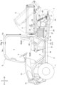
Fig. 1 is a left side view of a work vehicle. -
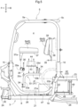
Fig. 2 is a plan view of a work vehicle. -
Fig. 3 is a left side view of members such as a body frame, a ROPS frame, a seat frame member, a first battery support section, and a second battery support section. -
Fig. 4 is a plan view of members such as a body frame, seat frame members, a first battery support section, and a second battery support section. -
Fig. 5 is an exploded left side view of members such as a body frame, a ROPS frame, a seat frame member, a first battery support section, and a second battery support section. -
Figs. 1 to 5 illustrate an electrically operated utility work vehicle as an example work vehicle.Figs. 1 to 5 show arrow F to indicate the forward direction, arrow B to indicate the backward direction, arrow U to indicate the upward direction, arrow D to indicate the downward direction, arrow L to indicate the leftward direction, and arrow R to indicate the rightward direction. - As illustrated in
Figs. 1 and2 , the work vehicle includes left and righttravel front wheels 1, left and righttravel rear wheels 2, and abody frame 3. The front wheels 1 (which correspond to the "travel device") are at a front portion of thebody frame 3. The rear wheels 2 (which correspond to the "travel device") are at a back portion of thebody frame 3. Thebody frame 3 is supported by the front andrear wheels - The work vehicle includes a
driver section 4 and a roll-over protective structure (ROPS)frame 5 that defines thedriver section 4. Thedriver section 4 is supported by a portion of thebody frame 3 which portion is between thefront wheels 1 and therear wheels 2, and is configured to accommodate a driver and a worker. Thedriver section 4 includes a driver's seat 6 (which corresponds to the "seat"), a passenger's seat 7 (which corresponds to the "seat"), afloor 8, and asteering wheel 9 for changing the direction of thefront wheels 1. - The work vehicle includes a
hood 10 forward of thedriver section 4 and acarrier box 11 backward of thedriver section 4. Thecarrier box 11 is capable of being lifted and lowered into a use orientation (indicated with solid lines inFig. 1 ) and a dumping orientation (indicated with double-dashed chain lines inFig. 1 ), in which thecarrier box 11 has a front portion lifted with a back lower portion as a pivot. - As illustrated in
Figs. 1 to 4 , thebody frame 3 includes left and rightfirst frame members 21, left and rightsecond frame members 22, left and rightthird frame members 23, left and rightfourth frame members 24, left and rightfifth frame members 25, and left and rightsixth frame members 26. - The
first frame members 21 extend in the front-back direction under the driver section 4 (specifically, the floor 8). Thesecond frame members 22 are each coupled to a back portion of the correspondingfirst frame member 21, extend upward therefrom, and are each backward of thedriver section 4. - The
third frame members 23 are each coupled to an upper portion of the correspondingsecond frame member 22, and extends backward therefrom. Thethird frame members 23 include respective upper portions on which thecarrier box 11 is disposed in such a manner as to be capable of being lifted and lowered into the use orientation and the dumping orientation. - The
fourth frame members 24 are each coupled to a front portion of the correspondingfirst frame member 21, and extend forward therefrom. The work vehicle includes left and rightvertical frame members 30 each coupled to the front portion of the correspondingfirst frame member 21 and extending upward therefrom. - The
fifth frame members 25 are each coupled to an upper portion of thecorresponding frame member 30, and extend forward therefrom. The work vehicle includes left and right front guards 12 each coupled to respective front portions of the corresponding fourth andfifth frame members - As illustrated in
Figs. 3 and4 , the work vehicle includes left and right front supports 15 each coupled to the upper portion of thecorresponding frame member 30, aframe member 13 coupled to the front supports 15, aframe member 14 coupled to respective front portions of thethird frame members 23, and left and right back supports 16 coupled respectively to left and right portions of theframe member 14. - The
sixth frame members 26 are each in a U shape (that is, a channel shape) in a side view, and each include a front upper portion coupled to the correspondingfront support 15 and a back upper portion coupled to thecorresponding back support 16. Thefloor 8 is coupled to respective front portions of thefirst frame members 21 and respective front lower portions of thesixth frame members 26. The work vehicle includes left and right side guards 40 each coupled to thecorresponding back support 16 and to a back lower portion of the correspondingsixth frame member 26. - With the above configuration, the work vehicle includes front wheels 1 ("travel device", "front travel device"), rear wheels 2 ("travel device", "rear travel device"), and a
driver section 4 including a driver's seat 6 ("seat") and a passenger's seat 7 ("seat") and disposed between the front wheels 1 ("front travel device") and the rear wheels 2 ("rear travel device") in a side view. - The work vehicle includes a
body frame 3 provided with the front wheels 1 ("travel device") and the rear wheels 2 ("travel device") and supporting thedriver section 4. Thebody frame 3 includesfirst frame members 21,second frame members 22, andthird frame members 23. Thefirst frame members 21 are under thedriver section 4. Thesecond frame members 22 each extend upward from a back portion of the correspondingfirst frame member 21, and are backward of thedriver section 4. Thethird frame members 23 each extend backward from an upper portion of the correspondingsecond frame member 22. The work vehicle includes acarrier box 11 over thethird frame members 23. - As illustrated in
Figs. 1 ,2 , and3 , thebody frame 3 is provided with left andright attachment sections 19 each coupled to a portion at which a back portion of the correspondingfirst frame member 21 is coupled to a lower portion of the correspondingsecond frame member 22. The work vehicle includes left and right suspension links 27 and left and right suspension links 28 each attached to thecorresponding attachment section 19 in a vertically swingable manner and each extending backward from thecorresponding attachment section 19. - The work vehicle includes an
axle frame 50 and arear axle case 17 coupled to theaxle frame 50 and including left and right portions each supporting the correspondingrear wheel 2. The work vehicle includes left andright attachment sections 20 coupled respectively to the left and right portions of theaxle frame 50. The suspension links 27 and 28 each include a back portion attached to thecorresponding attachment section 20 in a vertically swingable manner. - The work vehicle includes a
lateral rod 51 connected to a back portion of the rightthird frame member 23 and to theaxle frame 50. Thelateral rod 51 allows the axle frame 50 (and the rear axle case 17) to move vertically and prevents the axle frame 50 (and the rear axle case 17) from moving laterally. - The suspension links 27 and 28 and the
lateral rod 51 form a five-link mechanism that allows the axle frame 50 (and the rear axle case 17) to be supported by thebody frame 3 in a vertically movable manner. - The work vehicle includes left and
right suspension mechanisms 29 each including a suspension spring and a damper. Theright suspension mechanism 29 is connected to the rightthird frame member 23 and to a right portion of therear axle case 17, whereas theleft suspension mechanism 29 is connected to the leftthird frame member 23 and to a left portion of therear axle case 17. Thesuspension mechanisms 29 are thus coupled to the suspension links 27 and 28 with theaxle frame 50 and therear axle case 17 in-between. - As illustrated in
Figs. 1 ,2 , and3 , the work vehicle includes anauxiliary transmission device 46 coupled to an upper portion of a laterally central portion of therear axle case 17 and amotor 18 coupled to a front portion of theauxiliary transmission device 46. Themotor 18 is forward and upward relative to the rear axle case 17 (and the rear wheels 2) in a side view. - The
rear wheels 2, themotor 18, and theauxiliary transmission device 46 are thus supported by respective back portions of the suspension links 27 and 28 with theaxle frame 50 and therear axle case 17 in-between. - The
motor 18 transmits motive power to theauxiliary transmission device 46, which varies the motive power and transmits the varied motive power to therear wheels 2 through a rear-wheel differential device (not illustrated in the drawings) and a drive shaft (not illustrated in the drawings) inside therear axle case 17. - As illustrated in
Figs. 2 and3 , theROPS frame 5 includes left and rightfirst portions 5a, asecond portion 5b, and athird portion 5c. - The
first portions 5a are each in the shape of an inverted U (that is, an inverted channel) in a side view. Thesecond portion 5b is coupled to respective front portions of thefirst portions 5a. Thethird portion 5c is coupled to respective back portions of thefirst portions 5a. - The
first portions 5a each include a front lower portion coupled to the correspondingfront support 15 with use of a bolt (not illustrated in the drawings), whereas thefirst portions 5a each include a back lower portion coupled to thecorresponding back support 16 with use of a bolt (not illustrated in the drawings). TheROPS frame 5 is attached to thebody frame 3 as described above. - Removing the front lower portion of each
first portion 5a from the correspondingfront support 15 and the back lower portion of eachfirst portion 5a from the corresponding backsupport 16 allows theROPS frame 5 to be removed from thebody frame 3. - As illustrated in
Figs. 3 ,4 , and5 , the work vehicle includes left and rightseat frame members 33. Theseat frame members 33 are each in the form of an angular pipe bent in an L shape, and each include an up-downportion 33a extending in the up-down direction and a front-back portion 33b extending backward from an upper portion of the up-downportion 33a. - The
seat frame members 33 include asupport 33c coupled to the respective upper portions of the up-downportions 33a (or respective front portions of the front-back portions 33b) and asupport 33d coupled to respective back portions of the front-back portions 33b. - The
body frame 3 is configured such that thefirst frame members 21 each include a back portion provided with anattachment section 21a and that thesecond frame members 22 each include an upper portion provided with anattachment section 22a. - The
seat frame members 33 are configured such that the up-downportions 33a each include a lower portion attachable to thecorresponding attachment section 21a with use of abolt 34 and detachable therefrom and that the front-back portions 33b each include a back portion attachable to thecorresponding attachment section 22a with use of abolt 34 and detachable therefrom. - As illustrated in
Figs. 3 ,4 , and5 , the work vehicle includes asupport frame member 35 in the form of an angular pipe provided withpivot sections 35a. Thesupport frame member 35 is attachable to thesupport 33c of eachseat frame member 33 with use of abolt 36 and detachable therefrom. - As illustrated in
Figs. 1 and2 , the driver'sseat 6 includes aseating section 6a and abackrest 6b separate from theseating section 6a, whereas the passenger'sseat 7 includes aseating section 7a and abackrest 7b separate from theseating section 7a. - As illustrated in
Figs. 3 and5 , the work vehicle includes a plate-shapedsupport member 37 provided with left andright legs 37a each under a front portion thereof. Theseating sections support member 37. Thelegs 37a are each attached to apivot section 35a in such a manner that thesupport member 37 is swingable about an axis extending in the left-right direction A 1. - The work vehicle includes a plate-shaped
support member 38 to which thebackrests first portion 5a of theROPS frame 5 with use of abolt 39 and detachable therefrom. - With the work vehicle in normal use, the
support member 37 has a front portion supported by theseat frame members 33 with thesupport frame member 35 in-between and a back portion supported by thesupport 33d of theseat frame members 33. - With the work vehicle in normal use, the
seating sections seat frame members 33, and thereby supported by thebody frame 3 with theseat frame members 33 in-between. With the work vehicle in normal use, thebackrests ROPS frame 5, and thereby supported by thebody frame 3 with theROPS frame 5 in-between. - Lifting a back portion of the
support member 37 with eachpivot section 35a on thesupport frame member 35 as a pivot creates an open space over theseat frame members 33. Removing eachbolt 36 and removing thesupport frame member 35 from theseat frame members 33 allows theseating sections seat frame members 33. - Removing each
bolt 39 and removing thesupport member 38 from theROPS frame 5 allows thebackrests - As illustrated in
Figs. 3 ,4 , and5 , thebody frame 3 is provided with a plate-shapedsupport member 47 coupled to respective back portions of thefirst frame members 21. - The
body frame 3 has a quadrangular space in a side view as defined by (i) the up-downportions 33a, that is, those portions of theseat frame members 33 which extend in the up-down direction, (ii) the front-back portions 33b, that is, those portions of theseat frame members 33 which extend horizontally (or therespective seating sections seat 6 and the passenger's seat 7), (iii) the horizontal first frame members 21 (or the support member 47), and (iv) thesecond frame members 22, which extend in the up-down direction. The space serves as a firstbattery support section 31. - With the above configuration, the work vehicle includes under the driver's seat 6 ("seat") and the passenger's seat 7 ("seat") a first
battery support section 31 in which to mount a battery 41 ("first battery"). - As illustrated in
Figs. 3 ,4 , and5 , the battery 41 (which corresponds to the "first battery") is attachable to thesupport member 47 with use of bolts (not illustrated in the drawings) and detachable therefrom. Thebattery 41 is mounted in the firstbattery support section 31. - The
battery 41 is, in a plan view, in the shape of a rectangle withlong sides 41a andshort sides 41b. Thebattery 41 as mounted in the firstbattery support section 31 haslong sides 41a in the left-right direction A1. - The
battery 41 as mounted in the firstbattery support section 31 is, in a side view, between the up-downportion 33a of eachseat frame member 33 and the correspondingsecond frame member 22 and between the front-back portion 33b of eachseat frame member 33 and the correspondingfirst frame member 21. - The right
short side 41b is, in a plan view, to the right of the rightseat frame member 33 and toward the lateral center of thebody frame 3 relative to the rightsixth frame member 26 and theright side guard 40. The rightshort side 41b, in a side view, overlaps with the rightsixth frame member 26 and theright side guard 40. - The left
short side 41b is, in a plan view, to the left of the leftseat frame member 33 and toward the lateral center of thebody frame 3 relative to the leftsixth frame member 26 and theleft side guard 40. The leftshort side 41b, in a side view, overlaps with the leftsixth frame member 26 and theleft side guard 40. - As illustrated in
Figs. 3 ,4 , and5 , the work vehicle includes a plate-shapedsupport member 43 attachable to the respective front-back portions 33b of theseat frame members 33 each with use of a bolt (not illustrated in the drawings) and detachable therefrom. The work vehicle includes aninverter 44 and acontroller 45 both attached to thesupport member 43 and disposed, in a side view, between (i) therespective seating sections seat 6 and the passenger's seat 7 (or the support member 37) and (ii) the first battery support section 31 (or the respective front-back portions 33b of the seat frame members 33). - In response to a driver on the driver's
seat 6 pressing a shift pedal (not illustrated in the drawings), thecontroller 45 receives information on the position of the shift pedal as pressed and operates theinverter 44 on the basis of the position. - The
inverter 44 converts direct-current electric power from thebattery 41 and a battery 42 (described later) into alternating-current electric power and supplies the alternating-current electric power to themotor 18. Themotor 18, in response, operates to generate travel motive power and supplies the travel motive power to therear wheels 2 as mentioned above. With the above configuration, the work vehicle includesbatteries motor 18 configured to generate motive power on the basis of electric power from thebatteries - As illustrated in
Figs. 3 ,4 , and5 , lifting a back portion of thesupport member 37 with eachpivot section 35a on thesupport frame member 35 as a pivot creates an open space over theseat frame members 33 as mentioned above. - Lifting the
support member 37 allows theinverter 44 and thecontroller 45 to be maintained. Removing thesupport member 43 from theseat frame members 33 removes theinverter 44 and thecontroller 45. Lifting thesupport member 37 and removing theinverter 44 and thecontroller 45 allows thebattery 41 to be maintained. - Removing the
support frame member 35 from theseat frame members 33 and removing therespective seating sections seat 6 and the passenger'sseat 7 from theseat frame members 33 as mentioned above allows thebolts 34 to be removed and theseat frame members 33 to be removed from the body frame 3 (specifically, from thefirst frame members 21 and the second frame members 22). - Removing the
seat frame members 33 from the body frame 3 (specifically, from thefirst frame members 21 and the second frame members 22) allows thebattery 41 to be removed from and mounted in the firstbattery support section 31. - Removing the
bolts 39, removing thesupport member 38 from theROPS frame 5, and removing thebackrests battery 41. - In addition to removing the
backrests first portion 5a from the correspondingfront support 15, removing the back lower portion of eachfirst portion 5a from the corresponding backsupport 16, and removing theROPS frame 5 from thebody frame 3 as mentioned above further facilitates mounting and removing thebattery 41. - As illustrated in
Figs. 3 ,4 , and5 , thebody frame 3 is provided with a plate-shapedsupport base 48 coupled to respective lower portions of the second frame members 22 (which lower portions are proximate to the respective attachment sections 19) and extending backward from thesecond frame members 22. - The work vehicle includes a right
support frame member 49 coupled to the rightthird frame member 23 and to a back right portion of thesupport base 48 and a leftsupport frame member 49 coupled to the leftthird frame member 23 and to a back left portion of thesupport base 48. - The
body frame 3 has a quadrangular space in a side view as defined by (i) thesecond frame members 22, which extend in the up-down direction, (ii) the horizontalthird frame members 23, (iii) thehorizontal support base 48, and (iv) thesupport frame members 49, which extend in the up-down direction. The space serves as a second battery support section 32 (which corresponds to the "battery support section"). - The
support base 48 and thesupport frame members 49 are above the upper suspension links 27, which are each curved downward in a side view, and between the suspension links 27 and between the suspension links 28 in a plan view. - The
support base 48 and thesupport frame member 49 are forward of themotor 18, theauxiliary transmission device 46, therear axle case 17, and thesuspension mechanisms 29 in a side view. The battery 42 (which corresponds to the "second battery") is attachable to and detachable from thesupport base 48 as described later. - With the above configuration, the work vehicle includes a second battery support section 32 ("battery support section") in which the battery 42 ("second battery") is mountable and from which the
battery 42 is removable. - The
driver section 4 is, in a side view, between the front wheels 1 ("front travel device") and the rear wheels 2 ("rear travel device"). The second battery support section 32 ("battery support section") is, in a side view, between thedriver section 4 and the rear wheels 2 ("rear travel device"). - The
motor 18 is, in a side view, between thedriver section 4 and the rear wheels 2 ("rear travel device"). The second battery support section 32 ("battery support section") is, in a side view, between thedriver section 4 and themotor 18. - The second battery support section 32 ("battery support section") is below the
respective seating sections seat 6 and the passenger'sseat 7. - The second battery support section 32 ("battery support section") is backward of the
second frame members 22 of thebody frame 3 and below thethird frame members 23 of thebody frame 3. - The second battery support section 32 ("battery support section") includes a
support base 48 andsupport frame members 49 coupled to the respectivethird frame members 23 and thesupport base 48. Thesupport base 48 is coupled to respective back portions of thefirst frame members 21 of thebody frame 3 or to the respectivesecond frame members 22, and extends backward. The battery 42 ("second battery") is attachable to thesupport base 48. - The work vehicle includes suspension links 27 and 28 held by respective back portions of the
first frame members 21 or respective lower portions of thesecond frame members 22 in a vertically swingable manner and extending backward below the second battery support section 32 ("battery support section") in a side view. - The work vehicle includes
suspension mechanisms 29 backward of the second battery support section 32 ("battery support section"), connected to the respectivethird frame members 23, and coupled to therespective suspension links 27 and the respective suspension links 28. The rear wheels 2 ("rear travel device") are each held by respective back portions of the corresponding suspension links 27 and 28. - As illustrated in
Figs. 3 ,4 , and5 , the battery 42 (which corresponds to the "second battery") is attachable to thesupport base 48 with use of bolts (not illustrated in the drawings) and detachable therefrom. Thebattery 42 is mounted in the secondbattery support section 32. - The
battery 42 is, in a plan view, in the shape of a rectangle withlong sides 42a andshort sides 42b. Thebattery 42 as mounted in the secondbattery support section 32 haslong sides 42a in the left-right direction A1. - The
battery 42 is identical to the battery 41: Thelong sides 42a are equal in dimension to thelong sides 41a, whereas theshort sides 42b are equal in dimension to theshort sides 41b. - The
battery 42 as mounted in the secondbattery support section 32 is, in a side view, between eachthird frame member 23 of thebody frame 3 and thesupport base 48 and between eachsecond frame member 22 of thebody frame 3 and the correspondingsupport frame member 49. - The right
short side 42b is, in a plan view, to the right of a right portion of thesupport base 48 and the rightsupport frame member 49 and toward the lateral center of thebody frame 3 relative to the rightsixth frame member 26 and theright side guard 40. - The left
short side 42b is, in a plan view, to the left of a left portion of thesupport base 48 and the leftsupport frame member 49 and toward the lateral center of thebody frame 3 relative to the leftsixth frame member 26 and theleft side guard 40. - As illustrated in
Figs. 2 and4 , to mount thebattery 42 in the secondbattery support section 32, a worker places thebattery 42 on a cart (not illustrated in the drawings) with a height substantially equal to the height of the second battery support section 32 (specifically, of the support base 48). - The worker then places the cart (or the battery 42) to the left of the second
battery support section 32 and orients the cart so that thelong sides 42a are in the left-right direction A1. The worker then moves the cart (or the battery 42) to the right in the left-right direction A1 toward the secondbattery support section 32 until the cart (or the battery 42) comes into contact with, for example, thebody frame 3 and stops. - The worker then moves the
battery 42 from the cart to the right in the left-right direction A1 to insert the rightshort side 42b into the secondbattery support section 32 and move thebattery 42 further to the right, thereby moving thebattery 42 from the cart onto thesupport base 48. The worker can bolt thebattery 42 to thesupport base 48 to mount thebattery 42 in the secondbattery support section 32. - If a worker places the cart (or the battery 42) to the right of the second
battery support section 32, the worker can similarly orient the cart so that thelong sides 42a are in the left-right direction A1 and move the cart (or the battery 42) to the left in the left-right direction A1 toward the secondbattery support section 32 to mount thebattery 42 in the secondbattery support section 32. - As illustrated in
Figs. 2 and4 , to remove thebattery 42 from the secondbattery support section 32, a worker places an empty cart to the left of the secondbattery support section 32. - The worker removes the bolts with which the
battery 42 is attached to thesupport base 48, and then moves thebattery 42 to the left in the left-right direction A1 to place the leftshort side 42b onto the cart. The worker then moves thebattery 42 further to the left to move thebattery 42 from thesupport base 48 onto the cart, thereby removing thebattery 42 from the secondbattery support section 32. - If a worker places an empty cart to the right of the second
battery support section 32, the worker similarly moves thebattery 42 to the right in the left-right direction A1 to move thebattery 42 from thesupport base 48 onto the cart, thereby removing thebattery 42 from the secondbattery support section 32. - With the above configuration, moving the battery 42 ("second battery") from the left or right of the second battery support section 32 ("battery support section") in the left-right direction A1 allows the
battery 42 to be mounting in the second battery support section 32 ("battery support section"), whereas moving thebattery 42 from the second battery support section 32 ("battery support section") to the left or right in the left-right direction A1 allows thebattery 42 to be removed from the second battery support section 32 ("battery support section"). - If the work vehicle does not include a
battery 42 in the secondbattery support section 32, the secondbattery support section 32 is usable as, for example, a space for storing tools and baggage. - The work vehicle may, in this case, include in the second battery support section 32 a storage box (not illustrated in the drawings) with a door. Storing tools and baggage in the storage box prevents the tools and baggage from falling onto the ground due to, for example, vibration during travel, and protects the tools and baggage from soil or water on the ground.
- The work vehicle may include left and right under covers (not illustrated in the drawings) coupled respectively to left and right portions of the
support base 48 and configured to protect thebattery 42 in the secondbattery support section 32 from soil or water on the ground. - The second alternative embodiment may be further altered such that the work vehicle includes left and right side covers (not illustrated in the drawings) disposed respectively at a left portion of the left under cover and a right portion of the right under cover and configured to be opened and closed. With this configuration, the side covers protect left and right portions of the
battery 42 in the secondbattery support section 32. - The work vehicle may be configured such that the
attachment sections 19 are each coupled to a back portion of the correspondingfirst frame member 21 and that the suspension links 27 and 28 are each held by the back portion of the correspondingfirst frame member 21 in a vertically swingable manner. - The work vehicle may be configured such that the
attachment sections 19 are each coupled to a lower portion of the correspondingsecond frame member 22 and that the suspension links 27 and 28 are each held by the lower portion of the correspondingsecond frame member 22 in a vertically swingable manner. - The work vehicle may be configured such that the
support base 48 is coupled to respective back portions of the first frame members 21 (which back portions are proximate to the respective attachment sections 19) and extends backward therefrom. - The work vehicle may omit the suspension links 27 and 28 and the
lateral rod 51 and include a double wishbone suspension (not illustrated in the drawings) to allow therear wheels 2 to be held by the respectivethird frame members 23 of thebody frame 3. - The work vehicle may, in this case, be of a four-wheel drive such that the
motor 18 transmits its motive power through a power transmission shaft (not illustrated in the drawings) and a front-wheel differential device (not illustrated in the drawings) to thefront wheels 1. - The work vehicle may be configured such that the
driver section 4 includes a driver'sseat 6 and a passenger'sseat 7 on the front row and an additional seat (not illustrated in the drawings) on the back row to accommodate four persons in total. - The work vehicle should, in this case, include a
battery 41 under a backseat configured as illustrated inFigs. 3 ,4 , and5 . If thebatteries seat 6 and the passenger'sseat 7. - The work vehicle may include a crawler travel device (not illustrated in the drawings) in place of the
front wheels 1 as the front travel device or in place of therear wheels 2 as the rear travel device. The work vehicle may include a single crawler travel device (not illustrated in the drawings) in place of both thefront wheels 1 and therear wheels 2. - The present invention is applicable to not only an electrically operated work vehicle including a motor configured to drive its travel device, but also a hybrid work vehicle including an engine and a motor each configured to drive its travel device.
-
- 1
- Front wheel (travel device)
- 2
- Rear wheel (travel device)
- 3
- Body frame
- 4
- Driver section
- 6
- Driver's seat (seat)
- 7
- Passenger's seat (seat)
- 11
- Carrier box
- 18
- Motor
- 21
- First frame member
- 22
- Second frame member
- 23
- Third frame member
- 27
- Suspension link
- 28
- Suspension link
- 29
- Suspension mechanism
- 32
- Second battery support section (battery support section)
- 42
- Battery
- 42a
- Long side
- 42b
- Short side
- 48
- Support base
- 49
- Support frame member
- A1
- Left-right direction
Claims (9)
- A work vehicle, comprising:at least one travel device (1, 2); a driver section (4) including a seat (6, 7); a battery (42); a motor (18) configured to supply motive power to the at least one travel device (1, 2) with use of electric power from the battery (42); and a battery support section (32) in which the battery (42) is mountable and from which the battery is removable,wherein moving the battery (42) from left or right of the battery support section (32) in a left-right direction (A1) allows the battery (42) to be mounted in the battery support section (32), andmoving the battery (42) from the battery support section (32) to the left or right of the battery support section (32) in the left-right direction (A1) allows the battery (42) to be removed from the battery support section (32).
- The work vehicle according to claim 1, whereinthe at least one travel device (1, 2) includes a front travel device (1) and a rear travel device (2),the driver section (4) is between the front travel device (1) and the rear travel device (2) in a side view, andthe battery support section (32) is between the driver section (4) and the rear travel device (2) in a side view.
- The work vehicle according to claim 2, whereinthe motor (18) is between the driver section (4) and the rear travel device (2) in a side view, andthe battery support section (32) is between the driver section (4) and the motor (18) in a side view.
- The work vehicle according to claim 2 or 3, wherein
the battery support section (32) is below the seat (6, 7). - The work vehicle according to any one of claims 1 to 4, further comprising:a body frame (3) for which the at least one travel device (1, 2) is provided and which supports the driver section (4),wherein the body frame (3) includes:a first frame member (21) under the driver section (4);a second frame member (22) extending upward from a back portion of the first frame member (21) and disposed backward of the driver section (4); anda third frame member (23) extending backward from an upper portion of the second frame member (22), andthe battery support section (32) is backward of the second frame member (22) and below the third frame member (23).
- The work vehicle according to claim 5, wherein
the battery support section (32) includes:a support base (48) coupled to a back portion of the first frame member (21) or to the second frame member (22) and extending backward, to which support base (48) the battery (42) is attachable; anda support frame member (49) coupled to the third frame member (23) and the support base (48). - The work vehicle according to claim 5 or 6, further comprising:
a carrier box (11) over the third frame member (23). - The work vehicle according to any one of claims 5 to 7, further comprising:a suspension link (27, 28) held by a back portion of the first frame member (21) or a lower portion of the second frame member (22) in a vertically swingable manner and extending backward below the battery support section (32) in a side view; anda suspension mechanism (29) backward of the battery support section (32) and coupled to the third frame member (23) and the suspension link (27, 28),wherein the rear travel device (2) is held by a back portion of the suspension link (27, 28).
- The work vehicle according to any one of claims 1 to 8, whereinthe battery (42) is in a shape of a rectangle with a long side (42a) and a short side (42b) in a plan view, andthe battery (42) is mountable in the battery support section (32) with the long side (42a) in the left-right direction (A1).
Applications Claiming Priority (1)
| Application Number | Priority Date | Filing Date | Title |
|---|---|---|---|
| JP2022181288A JP7849277B2 (en) | 2022-11-11 | 2022-11-11 | Work vehicle |
Publications (1)
| Publication Number | Publication Date |
|---|---|
| EP4368431A1 true EP4368431A1 (en) | 2024-05-15 |
Family
ID=88779872
Family Applications (1)
| Application Number | Title | Priority Date | Filing Date |
|---|---|---|---|
| EP23208922.7A Pending EP4368431A1 (en) | 2022-11-11 | 2023-11-09 | Work vehicle |
Country Status (3)
| Country | Link |
|---|---|
| US (1) | US20240157818A1 (en) |
| EP (1) | EP4368431A1 (en) |
| JP (1) | JP7849277B2 (en) |
Citations (3)
| Publication number | Priority date | Publication date | Assignee | Title |
|---|---|---|---|---|
| US20120226405A1 (en) * | 2009-06-15 | 2012-09-06 | Polaris Industries Inc. | Electric vehicle |
| JP2013141875A (en) | 2012-01-10 | 2013-07-22 | Kubota Corp | Electric tractor |
| EP3987902A1 (en) * | 2019-06-24 | 2022-04-27 | Kubota Corporation | Electric work vehicle |
Family Cites Families (4)
| Publication number | Priority date | Publication date | Assignee | Title |
|---|---|---|---|---|
| WO2013006949A1 (en) | 2011-07-08 | 2013-01-17 | Consortium De Recherche Brp - Universite De Sherbrooke S.E.N.C. | Electric off-road wheeled vehicle |
| WO2014057514A1 (en) | 2012-10-10 | 2014-04-17 | 川崎重工業株式会社 | Electric vehicle |
| JP6600260B2 (en) | 2016-02-04 | 2019-10-30 | 本田技研工業株式会社 | 4 wheel vehicle |
| CN110914087A (en) | 2017-08-31 | 2020-03-24 | 本田技研工业株式会社 | Electric vehicle |
-
2022
- 2022-11-11 JP JP2022181288A patent/JP7849277B2/en active Active
-
2023
- 2023-11-09 EP EP23208922.7A patent/EP4368431A1/en active Pending
- 2023-11-10 US US18/388,647 patent/US20240157818A1/en active Pending
Patent Citations (3)
| Publication number | Priority date | Publication date | Assignee | Title |
|---|---|---|---|---|
| US20120226405A1 (en) * | 2009-06-15 | 2012-09-06 | Polaris Industries Inc. | Electric vehicle |
| JP2013141875A (en) | 2012-01-10 | 2013-07-22 | Kubota Corp | Electric tractor |
| EP3987902A1 (en) * | 2019-06-24 | 2022-04-27 | Kubota Corporation | Electric work vehicle |
Also Published As
| Publication number | Publication date |
|---|---|
| JP2024070662A (en) | 2024-05-23 |
| JP7849277B2 (en) | 2026-04-21 |
| US20240157818A1 (en) | 2024-05-16 |
Similar Documents
| Publication | Publication Date | Title |
|---|---|---|
| JP4259694B2 (en) | Vehicle battery mounting structure | |
| JP6600260B2 (en) | 4 wheel vehicle | |
| US8720636B2 (en) | Motor vehicle having an electromotive unit and the power supply module thereof arranged in the vicinity of a running gear of the vehicle | |
| CN111902337B (en) | electric vehicle | |
| CN111886176B (en) | electric vehicle | |
| CN110893756B (en) | vehicle | |
| CN107031718A (en) | Four-wheel car | |
| EP2447099A1 (en) | Hybrid vehicle structure | |
| US20150291056A1 (en) | Electric Vehicle and Method of Carrying Out Battery for Electric Vehicle | |
| CN111902336B (en) | Electric vehicle | |
| JP5729207B2 (en) | Vehicle power supply support structure | |
| JP6880340B2 (en) | Mobile | |
| US11548555B2 (en) | Electric car sub-frame | |
| CN113891828B (en) | Electric truck frame | |
| JP7482080B2 (en) | Work vehicles | |
| JP3620242B2 (en) | Electric vehicle battery mounting structure | |
| CN215621426U (en) | Pure electric tractor | |
| US4834424A (en) | Lift truck | |
| CA1282377C (en) | Method and means for lift truck assembly and servicing | |
| EP4368431A1 (en) | Work vehicle | |
| EP4368430A1 (en) | Work vehicle | |
| JP2021075111A (en) | Support device of battery pack for vehicle | |
| JP2020090208A (en) | Vehicular battery pack support device | |
| JP2001097068A (en) | Electric car joint box structure | |
| JP4392836B2 (en) | Wheel loader |
Legal Events
| Date | Code | Title | Description |
|---|---|---|---|
| PUAI | Public reference made under article 153(3) epc to a published international application that has entered the european phase |
Free format text: ORIGINAL CODE: 0009012 |
|
| STAA | Information on the status of an ep patent application or granted ep patent |
Free format text: STATUS: REQUEST FOR EXAMINATION WAS MADE |
|
| 17P | Request for examination filed |
Effective date: 20231109 |
|
| AK | Designated contracting states |
Kind code of ref document: A1 Designated state(s): AL AT BE BG CH CY CZ DE DK EE ES FI FR GB GR HR HU IE IS IT LI LT LU LV MC ME MK MT NL NO PL PT RO RS SE SI SK SM TR |