EP4368368B1 - Dispositif d'emboutissage profond, machine d'emballage dotée d'un dispositif d'emboutissage profond et procédé de fonctionnement du dispositif d'emboutissage profond - Google Patents
Dispositif d'emboutissage profond, machine d'emballage dotée d'un dispositif d'emboutissage profond et procédé de fonctionnement du dispositif d'emboutissage profond Download PDFInfo
- Publication number
- EP4368368B1 EP4368368B1 EP22206801.7A EP22206801A EP4368368B1 EP 4368368 B1 EP4368368 B1 EP 4368368B1 EP 22206801 A EP22206801 A EP 22206801A EP 4368368 B1 EP4368368 B1 EP 4368368B1
- Authority
- EP
- European Patent Office
- Prior art keywords
- film
- deep
- hotplate
- vacuum
- drawing device
- Prior art date
- Legal status (The legal status is an assumption and is not a legal conclusion. Google has not performed a legal analysis and makes no representation as to the accuracy of the status listed.)
- Active
Links
Images

Classifications
-
- B—PERFORMING OPERATIONS; TRANSPORTING
- B29—WORKING OF PLASTICS; WORKING OF SUBSTANCES IN A PLASTIC STATE IN GENERAL
- B29C—SHAPING OR JOINING OF PLASTICS; SHAPING OF MATERIAL IN A PLASTIC STATE, NOT OTHERWISE PROVIDED FOR; AFTER-TREATMENT OF THE SHAPED PRODUCTS, e.g. REPAIRING
- B29C51/00—Shaping by thermoforming, i.e. shaping sheets or sheet like preforms after heating, e.g. shaping sheets in matched moulds or by deep-drawing; Apparatus therefor
- B29C51/26—Component parts, details or accessories; Auxiliary operations
- B29C51/42—Heating or cooling
- B29C51/421—Heating or cooling of preforms, specially adapted for thermoforming
- B29C51/422—Heating or cooling of preforms, specially adapted for thermoforming to produce a temperature differential
-
- B—PERFORMING OPERATIONS; TRANSPORTING
- B29—WORKING OF PLASTICS; WORKING OF SUBSTANCES IN A PLASTIC STATE IN GENERAL
- B29C—SHAPING OR JOINING OF PLASTICS; SHAPING OF MATERIAL IN A PLASTIC STATE, NOT OTHERWISE PROVIDED FOR; AFTER-TREATMENT OF THE SHAPED PRODUCTS, e.g. REPAIRING
- B29C51/00—Shaping by thermoforming, i.e. shaping sheets or sheet like preforms after heating, e.g. shaping sheets in matched moulds or by deep-drawing; Apparatus therefor
- B29C51/10—Forming by pressure difference, e.g. vacuum
-
- B—PERFORMING OPERATIONS; TRANSPORTING
- B29—WORKING OF PLASTICS; WORKING OF SUBSTANCES IN A PLASTIC STATE IN GENERAL
- B29C—SHAPING OR JOINING OF PLASTICS; SHAPING OF MATERIAL IN A PLASTIC STATE, NOT OTHERWISE PROVIDED FOR; AFTER-TREATMENT OF THE SHAPED PRODUCTS, e.g. REPAIRING
- B29C51/00—Shaping by thermoforming, i.e. shaping sheets or sheet like preforms after heating, e.g. shaping sheets in matched moulds or by deep-drawing; Apparatus therefor
- B29C51/26—Component parts, details or accessories; Auxiliary operations
- B29C51/42—Heating or cooling
- B29C51/421—Heating or cooling of preforms, specially adapted for thermoforming
- B29C51/425—Heating or cooling of preforms, specially adapted for thermoforming using movable heating devices
-
- B—PERFORMING OPERATIONS; TRANSPORTING
- B29—WORKING OF PLASTICS; WORKING OF SUBSTANCES IN A PLASTIC STATE IN GENERAL
- B29K—INDEXING SCHEME ASSOCIATED WITH SUBCLASSES B29B, B29C OR B29D, RELATING TO MOULDING MATERIALS OR TO MATERIALS FOR MOULDS, REINFORCEMENTS, FILLERS OR PREFORMED PARTS, e.g. INSERTS
- B29K2029/00—Use of polyvinylalcohols, polyvinylethers, polyvinylaldehydes, polyvinylketones or polyvinylketals or derivatives thereof as moulding material
- B29K2029/04—PVOH, i.e. polyvinyl alcohol
Definitions
- the invention relates to a thermoforming device having the features according to the preamble of claim 1 and a packaging machine for producing filled bags with such a thermoforming device as well as a method for operating the thermoforming device.
- packaging units are often produced by first thermoforming film.
- a product is poured into the resulting cavities, which are then sealed with a cover film.
- the film used in the packaging unit can withstand external stresses so that the packaged product is adequately protected. If, during the production process, it was discovered that the film was torn or partially thinned to the point where it was leaking, the film thickness was increased as a countermeasure. Forming process parameters, such as the preheating temperature or preheating time of the film, can also be adjusted. This can prevent defects in the film packaging. However, using a thicker film can lead to increased environmental impact. Furthermore, the necessary adjustments also result in increased manufacturing costs.
- a further disadvantage of the packaging machines known from the prior art arises particularly when using water-soluble films.
- Water-soluble films such as PVOH films, are well known from the prior art and are particularly useful for packaging detergents and cleaning agents, for example, for use in dishwashers or washing machines.
- the packaging units are placed in the corresponding machine and rinsed with water. As soon as the film dissolves, the detergent is released.
- the use of an increased film thickness causes an increase in the dissolution time of the packaging unit.
- extremely irregular, non-reproducible dissolution times of the packaging units have been observed.
- thermoforming device which enables a process-reliable, environmentally friendly and at the same time cost-effective production of filled film bags.
- a further object of the invention is to provide a packaging machine which enables a process-reliable, environmentally friendly and at the same time cost-effective production of filled film bags.
- a further object of the invention is to provide a method for deep-drawing film for the production of film packaging, which enables a process-reliable, environmentally friendly and at the same time cost-effective production of filled film bags.
- the invention is based on the finding that the irregular dissolution times of water-soluble films are at least largely due to uneven film thickness. Furthermore, it was determined that the uneven film thickness arises during the deep-drawing process. During deep-drawing, the film is laid over the die. Such dies have complex geometries with different depths and shape radii. This circumstance leads to the film being thinned differently locally within the die after deep-drawing and thus also having different film thicknesses locally.
- the shape of the heating plate makes it possible to apply different heat inputs locally to the film, thereby partially modifying its flow behavior. This allows the heat input to be reduced in the sections of the film subject to increased thinning, and the heat input to be increased in the sections of the film subject to reduced thinning.
- the film material flows more from the heated sections of the film, which have a material surplus.
- the material flow from the less heated sections of the film is reduced due to the lower heat input.
- This allows the material flow of the film to be specifically controlled, and the thinning process to be homogenized. Consequently, the film undergoes uniform thinning.
- the use of a film with increased film thickness to avoid material failure is no longer necessary.
- the packaging units can be produced in an environmentally friendly and cost-effective manner.
- the dissolution time of the films, especially the PVOH films, in water can also be adjusted in a process-safe and reproducible manner.
- the underside of the heating plate has a flat base surface, wherein the shape contour forms a depression starting from the base surface in the vertical direction towards the top of the heating plate.
- the base surface lies completely below the shape contour in the vertical direction.
- the shape contour of the heating plate has a greater distance from the film than the base surface of the Heating plate. This also reduces the heat input from the mold contour to the film compared to the base surface.
- the mold contour can be configured as a complex geometry so that the distances within the mold contour to the film vary locally. Thus, the heat input across the entire mold contour to the film section also varies locally.
- the mold contour has a multitude of different depths relative to the base surface. If parts of the mold contour are designed as free surfaces, these also have a multitude of different depths relative to the base surface. The resulting distances lead to locally different heat inputs to the film and thus to locally different flow behavior of the film.
- the heating plate is designed to be movable up and down vertically via a pressure plate. This allows the heat input to the film to be modified at least globally.
- At least one capillary opening is formed on the mold contour of the heating plate, wherein the at least one capillary opening is connected to a first vacuum source and/or a second vacuum source via a second vacuum channel.
- the capillary opening is preferably designed as a capillary bore. If a vacuum is applied to the mold contour, the film is sucked onto the mold contour of the heating plate and thereby pre-stretched. Particularly preferably, several capillary openings are provided in the mold contour. When the film is sucked onto the mold contour, the film comes into contact at least partially with the mold contour. The heat input to the film is increased in the areas in which the film comes into contact with the mold contour of the heating plate.
- several capillary bores are provided in the mold contour and arranged relative to one another in such a way that, when a vacuum is applied, the film contacts the mold contour in a targeted manner in those areas in which an increased Flow behavior is required. This can promote the locally different heating of the film in the film section between the die shape of the die plate and the shape contour of the heating plate.
- the heating of the film is combined with a targeted pre-stretching of the film.
- a vacuum is applied, in particular for the pre-stretching of the film, at the mold contour of the heating plate, whereby the film is sucked into the heating plate and adheres to the mold contour.
- the film contacts the mold contour, in particular in the areas of the capillary openings, whereby the film is exposed to increased heat transfer at the contact areas.
- the capillary holes are arranged, in particular, on the mold contour in such a way that the heat transfer through the direct contact between the film and the mold contour in the areas of the film where increased material flow is required.
- the film is deep-drawn into the die of the die plate by a vacuum applied to the die.
- the vacuum in the mold contour is preferably deactivated at the same time. This has the result that the deep-drawing force acting on the film, which is generated by the vacuum applied to the die, is not counteracted by a force generated by the vacuum on the mold contour.
- the overpressure is preferably variably adjustable. The overpressure corresponds to blown air.
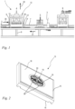
- Fig. 1 shows a side view of a section of a packaging machine 1 according to the invention for producing filled bags.
- the packaging machine 1 comprises a machine frame 8, a forming station 4, a filling station 5, and a sealing station 6.
- a film 2 is fed to the packaging machine 1 and deep-drawn in the forming station 4, so that cavities are formed in the film 2.
- the film 2 is designed as a film web. It may also be expedient to feed individual film sheets to the packaging machine.
- the cavities are filled with a product in the filling station 5.
- a cover film 3 is then fed in and sealed onto the films 2 in the sealing station 6, closing the filled cavities.
- the film unit thus formed is separated into film bags.
- the film 2 and the cover film 3 are water-soluble films, namely PVOH films, between which, for example, a washing or cleaning agent is packaged. Filled film bags produced in this way are placed in a dishwasher, for example. There, the film material dissolves upon contact with water and releases the detergent it contains. The same applies analogously to the use of such a film bag in a washing machine.
- the packaging machine 1 comprises the stationary machine frame 8 and a preferably continuously driven conveyor 7.
- the conveyor 7 can be a conveyor belt or the like and is in the preferred embodiment by articulated and chain-like elements are formed, on which a plurality of die plates 9, 9' are mounted.
- the latter are driven together with the conveyor 7, preferably continuously and in rotation around the machine frame 8, wherein they move on an upper horizontal track according to an arrow 30 for the actual production process of the bags and, after appropriate deflection, are then returned in the lower area of the machine frame 8 according to an arrow 31.
- the film 2, a preferably endless film web, is also preferably fed continuously and placed from above onto the conveyor 7 with the die plates 9, 9'.
- the cover film 3 is preferably fed continuously and placed from above onto the upper side of the film 2.
- the film 2 and the cover film 3 are moved synchronously and preferably continuously with the conveyor 7 in the applied state according to the arrow 30.
- the station for feeding the film 2 and the station for feeding the cover film 3 are stationary relative to the machine frame 8, as are stations (not shown) for applying water to support the sealing process and for perforating or laterally trimming the films. It can also be provided that the stations are at least partially attached to the machine frame 8.
- the movement of the conveyor 7 is continuous.
- the processes carried out here also operate continuously.
- the forming station 4, the filling station 5 and the sealing station 6 are not positioned stationary relative to the machine frame 8, but are moved in sections synchronously with the conveyor 7 over a certain distance.
- the film 2 is deep-drawn in the forming station 4, the product to be packaged is filled into the deep-drawn cavities in the filling station 5, and the cover film 3 is sealed onto the lower film 2 in the area of the sealing bars of the cavity in the sealing station 6.
- the forming station 4, the filling station 5, and the sealing station 6 cyclically move back to their starting position, where a new cycle of the currently executed process begins.
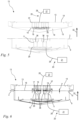
- the forming station 4 is formed by a deep-drawing device 12.
- the deep-drawing device 12 can be designed to accommodate only a single die plate 9, 9' and deep-draw the film 2 therein in one cycle. In the illustrated embodiment, the deep-drawing device 12 is designed to simultaneously accommodate several, here two consecutive, die plates 9, 9'.
- an individual die plate 9, 9' has at least one die mold 10 on its upper side.
- a die mold 10 is provided on each die plate 9, wherein the die mold is further divided into four individual cavities 36.
- 44 or 48 products are produced on a single die plate 9, 9' in one process run, accordingly 44 or 48 die molds 10 are formed on a die plate 9, 9'.
- Each die mold 10 can have one or more individual cavities 36.
- Each die mold 10, preferably each individual cavity 36, is provided with at least one capillary bore 11, preferably a plurality of capillary bores 11.
- the capillary bores 11 are part of a first vacuum channel 26, via which the die molds 10 are connected to a first vacuum source 21.
- the capillary bores 11 of a die mold 10 open into a common pressure chamber 29, whereby the capillary bores 11 are fluidly connected to one another. Thus, pressure equalization takes place between the individual capillary bores 11 via the pressure chamber 29.
- the pressure chamber 29 is also part of the first vacuum channel 26.
- the first vacuum source 21 generates a vacuum, i.e., a negative pressure, wherein the vacuum of the die mold 10 can be switched on via a valve (not shown in detail), which is functionally arranged in the first vacuum channel 26 between the vacuum source 21 and the die mold 10.
- a valve not shown in detail
- the deep-drawing device 12 comprises a heating plate 13.
- the heating plate 13 serves to heat the film 2 before it is deep-drawn. This promotes the material flow of the film.
- the die plate 9, 9' with the film 2 arranged thereon is positioned below the heating plate 13.
- the heating plate 13 is then lowered until a distance a is set between the heating plate 13 and the film 2.
- the distance a can be selected to be larger or smaller depending on the required flow behavior of the film 2, whereby the overall heat transfer from the heating plate 13 to the film 2 can be adjusted. It can also be expedient to select a distance a of zero in order to achieve maximum heat transfer to the film 2.
- the heating plate 13 is moved up and down in the vertical direction 32 via a pressure plate 34.
- the heating plate 13 has a shaped contour 16 ( Fig. 2 ).
- the heating plate 13 comprises an upper side 14 facing away from the die plate 9, 9' and a lower side 15 facing the die plate 9, 9'.
- the mold contour 16 is formed on the lower side 15 of the heating plate 13.
- the vertical direction 32 runs from the lower side 15 of the heating plate 13 to the upper side 14 of the heating plate 13.
- the vertical direction 32 is preferably opposite to the direction of gravity.
- the mold contour 16 is formed as a depression 19 in the heating plate 13.
- the mold contour 16 is designed in terms of its geometry such that when heating the film 2, the distances measured in the vertical direction 32 within the Surface of the mold contour 16 to the film 2 are different. As a result, the heat transfer from the heating plate 13 to the film 2 is also different, whereby the flow behavior of the film can be modified. Consequently, the geometry of the mold contour 16 of the die mold 10 is adapted such that the flow behavior of the film 2 in a film section 17, which lies between the mold contour 16 and the die mold 10, is favored during deep drawing.
- the mold contour 16 has an increased distance to the regions of the film section 17 that tend to increased thinning during deep drawing. This reduces the heat transfer to the corresponding regions of the film 2, reduces the material flow and prevents increased thinning.
- the geometry of the mold contour 16 is designed such that the mold contour 16 has a reduced distance to the regions of the film section 17 that tend to insufficient thinning during deep drawing. This increases the heat transfer to the corresponding areas of film 2, increases the material flow and prevents insufficient thinning.
- a flat base surface 18 is formed on the underside 15 of the heating plate 13.
- the recess 19 of the shape contour 16 extends, starting from the base surface 18 in the direction of the top side 14 of the heating plate 13.
- the base surface 18 is preferably arranged completely below the shape contour 16 with respect to the vertical direction 32.
- Parts of the shape contour 16 are designed as free-form surfaces 16, whereby the distances to the film 2 can be adjusted very variably.
- the shape contour 16, in particular the free-form surfaces of the shape contour 16 have a plurality of different depths t 1 , t 2 with respect to the base surface 18.
- the shape contour 16 is preferably milled into the heating plate 13.
- thermoforming device 12 For each matrix shape 10, a separate shape contour 16 adapted to the matrix shape 10 must therefore be created. If the die plates 9, 9' of a packaging machine 1 are replaced, the heating plate 13 of the thermoforming device 12 must also be replaced. In an alternative embodiment of the thermoforming device 12, it may be expedient to provide a separate contour plate that can be attached to the heating plate 13. In such a design, only the mold contour plate would have to be replaced, but not the entire heating plate 13.
- the film 2 can be deep-drawn by applying a vacuum in the die 10 of the die plate 9, 9'. Due to the targeted, local heating of the film section 17 of the film 2, the film section 17 exhibits an optimized, uniform film thickness distribution in the deep-drawn state.
- the Figures 5 and 6 show a particularly preferred embodiment of the deep-drawing device 12 according to the invention, which enables pre-stretching of the film 2.
- at least one capillary opening 35 is provided on the mold contour 16 of the heating plate 13.
- the at least one capillary opening 35 is connected to a second vacuum source 27 via a second vacuum channel 28.
- the second vacuum channel 28 is connected to the first vacuum source 21 or to both the first vacuum source 21 and the second vacuum source 27.
- the vacuum sources 21, 27 and the corresponding vacuum channels 26, 28 are shown only schematically in all figures.
- the second vacuum source 27 and the second vacuum channel 28 are also part of a mold vacuum device 20.
- a plurality of capillary openings 35 are provided on the mold contour 16.
- at least one, in particular a plurality of capillary openings 35 are provided in each individual cavity 36 of the mold contour 16.
- the capillary openings 35 are preferably formed as bores.
- the capillary openings 35 open into a second pressure chamber 37, via which the capillary openings 35 are fluidly connected to one another. Accordingly, pressure equalization between the capillary openings 35 of the mold contour 16 takes place via the second pressure chamber 37.
- the second pressure chamber 37 like the capillary openings 35 of the mold contour 16, is part of the second vacuum channel 28.
- a vacuum is applied to the mold contour 16 via the second and/or first vacuum source 21, 27, whereby the film section 17 of the film 2 is sucked onto the mold contour 16.
- the film 2 comes into contact with the mold contour 16, in particular in the area of the capillary openings 35. In these areas, the film 2 directly contacts the heating plate 13, thereby increasing the heat transfer to the film 2.
- the capillary openings 35 are preferably distributed along the mold contour 16 in such a way that the film comes into contact with the heating plate 13 in those areas where the flow behavior of the film 2 is to be favored.
- the same also applies to the pre-stretching of the film 2.
- the areas that are to have increased flow behavior are to be pre-stretched using the negative pressure of the capillary bores 35.
- the capillary openings 35 are to be distributed accordingly over the mold contour 16.
- the vacuum at the mold contour 16 is deactivated and, at the same time, the vacuum in the die 10 is activated.
- the film 2 is deep-drawn.
- an overpressure can also be applied to the mold contour 16 to facilitate the deep-drawing of the film 2.
- the overpressure is preferably variably adjustable. The overpressure corresponds to blown air. A new die plate 9, 9' is then assigned to the deep-drawing device 12, and the deep-drawing process is repeated.
Landscapes
- Engineering & Computer Science (AREA)
- Mechanical Engineering (AREA)
- Blow-Moulding Or Thermoforming Of Plastics Or The Like (AREA)
Claims (12)
- Dispositif d'emboutissage pour l'emboutissage de film,comprenant un agencement de plusieurs plaques de matrice (9, 9') qui peut être entraîné dans une voie de circulation par un transporteur (7),chaque plaque de matrice (9, 9') présentant au moins un moule de matrice (10), et avec au moins un appareil de vide de moule (20), l'appareil de vide de moule (20) comprenant au moins une première source de vide (21) pour fournir un vide, et l'au moins une première source de vide (21) pouvant être reliée par l'intermédiaire d'un premier canal de vide (26) à l'au moins un moule de matrice (10) de chaque plaque de matrice (9, 9') pour fournir un vide pour l'emboutissage du film (2),et avec au moins une plaque chauffante (13) pour chauffer le film (2), la plaque chauffante (13) présentant un côté supérieur (14) détourné des plaques de matrice (9, 9') et un côté inférieur (15) tourné vers la plaque de matrice (9, 9'), et avec une direction verticale (32) s'étendant depuis le côté inférieur (15) de la plaque chauffante (13) jusqu'au côté supérieur (14) de la plaque chauffante (13),caractérisé en ce que la plaque chauffante (13) présente sur le côté inférieur (15) au moins un contour de moule (16) correspondant au moule de matrice (10), le contour de moule (16) étant conçu de telle sorte qu'une section de film (17) du film (2), qui se trouve entre le contour de moule (16) de la plaque chauffante (13) et le moule de matrice (10), peut être chauffée localement de manière différente.
- Dispositif d'emboutissage selon la revendication 1,
caractérisé en ce que le côté inférieur (15) de la plaque chauffante (13) présente une surface de base plane (18), le contour de moule (16) formant un creux (19) en partant de la surface de base (18) dans la direction verticale (32) vers le côté supérieur (14) de la plaque chauffante (13). - Dispositif d'emboutissage selon la revendication 2,
caractérisé en ce que la surface de base (18) se situe complètement en dessous du contour de moule (16) par rapport à la direction verticale (32). - Dispositif d'emboutissage selon l'une quelconque des revendications 1 à 3,
caractérisé en ce que des parties du contour de moule (16) sont réalisées sous forme de surfaces de forme libre (33). - Dispositif d'emboutissage selon la revendication 4,
caractérisé en ce que le contour de moule (16), notamment les surfaces de forme libre du contour de moule (16), présente une pluralité de profondeurs (t) différentes par rapport à la surface de base (18). - Dispositif d'emboutissage selon l'une quelconque des revendications 1 à 5,
caractérisé en ce que la plaque chauffante (13) peut être déplacée vers le haut et vers le bas dans la direction verticale (32) par l'intermédiaire d'une plaque de pression (34). - Dispositif d'emboutissage selon l'une quelconque des revendications 1 à 6,
caractérisé en ce qu'au moins une ouverture capillaire (35) est réalisée sur le contour de moule (16) de la plaque chauffante (13), l'au moins une ouverture capillaire (35) étant reliée à une première source de vide (21) et/ou à une deuxième source de vide (27) par l'intermédiaire d'un deuxième canal de vide (28). - Machine d'emballage pour la fabrication d'emballages en film avec un dispositif d'emboutissage (12) selon l'une quelconque des revendications 1 à 7.
- Procédé d'emboutissage de film pour la fabrication d'emballages en film avec une machine d'emballage selon la revendication 8,
un film (2) étant amené à au moins une plaque de matrice (9, 9'), le film (2) étant chauffé localement de manière différente par la plaque chauffante (13) dans la section de film (17) entre le contour de moule (16) de la plaque chauffante (13) et le moule de matrice (10). - Procédé selon la revendication 9,
caractérisé en ce que, pour chauffer le film (2), la plaque chauffante (13) est abaissée en direction de la plaque de matrice (9, 9') jusqu'à atteindre une distance (a) entre la plaque de matrice (9) et la plaque chauffante (13), la distance (a) étant réglable pour réguler le transfert de chaleur au film (2). - Procédé selon la revendication 10,
caractérisé en ce que, pour préétirer le film (2), un vide est appliqué sur le contour de moule (16) de la plaque chauffante (13), moyennant quoi le film (2) est aspiré par la plaque chauffante (13) et s'applique sur le contour de moule (16). - Procédé selon l'une quelconque des revendications 9 à 11,
caractérisé en ce que le film (2), notamment après un pré-étirage, est embouti dans le moule de matrice (10) de la plaque de matrice (9, 9') par un vide appliqué au moule de matrice (10).
Priority Applications (3)
| Application Number | Priority Date | Filing Date | Title |
|---|---|---|---|
| EP22206801.7A EP4368368B1 (fr) | 2022-11-10 | 2022-11-10 | Dispositif d'emboutissage profond, machine d'emballage dotée d'un dispositif d'emboutissage profond et procédé de fonctionnement du dispositif d'emboutissage profond |
| PL22206801.7T PL4368368T3 (pl) | 2022-11-10 | 2022-11-10 | Urządzenie do formowania wgłębnego, maszyna pakująca z urządzeniem do formowania wgłębnego i sposób eksploatacji urządzenia do formowania wgłębnego |
| ES22206801T ES3036758T3 (en) | 2022-11-10 | 2022-11-10 | Deep drawing device, packaging machine with a deep drawing device and method for operating the deep drawing device |
Applications Claiming Priority (1)
| Application Number | Priority Date | Filing Date | Title |
|---|---|---|---|
| EP22206801.7A EP4368368B1 (fr) | 2022-11-10 | 2022-11-10 | Dispositif d'emboutissage profond, machine d'emballage dotée d'un dispositif d'emboutissage profond et procédé de fonctionnement du dispositif d'emboutissage profond |
Publications (2)
| Publication Number | Publication Date |
|---|---|
| EP4368368A1 EP4368368A1 (fr) | 2024-05-15 |
| EP4368368B1 true EP4368368B1 (fr) | 2025-05-14 |
Family
ID=84367047
Family Applications (1)
| Application Number | Title | Priority Date | Filing Date |
|---|---|---|---|
| EP22206801.7A Active EP4368368B1 (fr) | 2022-11-10 | 2022-11-10 | Dispositif d'emboutissage profond, machine d'emballage dotée d'un dispositif d'emboutissage profond et procédé de fonctionnement du dispositif d'emboutissage profond |
Country Status (3)
| Country | Link |
|---|---|
| EP (1) | EP4368368B1 (fr) |
| ES (1) | ES3036758T3 (fr) |
| PL (1) | PL4368368T3 (fr) |
Family Cites Families (3)
| Publication number | Priority date | Publication date | Assignee | Title |
|---|---|---|---|---|
| JPS5258693A (en) * | 1975-11-07 | 1977-05-14 | Sumitomo Chem Co Ltd | Heat molding method of plastic corrugated hardboard |
| US9457510B2 (en) * | 2010-06-01 | 2016-10-04 | William C. Shanley, Iv | Apparatus and methods for selective thermoforming |
| ES2751657T3 (es) * | 2015-04-09 | 2020-04-01 | Koch Pac Systeme Gmbh | Dispositivo calefactor para calentar una lámina |
-
2022
- 2022-11-10 ES ES22206801T patent/ES3036758T3/es active Active
- 2022-11-10 EP EP22206801.7A patent/EP4368368B1/fr active Active
- 2022-11-10 PL PL22206801.7T patent/PL4368368T3/pl unknown
Also Published As
| Publication number | Publication date |
|---|---|
| PL4368368T3 (pl) | 2025-10-13 |
| ES3036758T3 (en) | 2025-09-24 |
| EP4368368A1 (fr) | 2024-05-15 |
Similar Documents
| Publication | Publication Date | Title |
|---|---|---|
| DE69513121T2 (de) | Verfahren zur Herstellung von thermoplastischen Kunststoffformteilen | |
| DE10030010C2 (de) | Verfahren zum Herstellen eines Behälters aus einer thermoplastischen Kunststofffolie und Formwerkzeug zur Durchführung des Verfahrens | |
| DE8007086U1 (de) | Vorrichtung zum formen von behaeltnissen aus einer folie | |
| DE102012018974B4 (de) | Tiefziehverpackungsmaschine mit Stempelformung | |
| EP1142691B1 (fr) | Procédé pour la fabrication d'un récipient en feuille thermoplastique et machine de formage et poinçonnage combinée pour mettre ledit procédé en oeuvre | |
| DE3216332C2 (de) | Vorrichtung zum Herstellen eines dreidimensional geformten Schichtkörpers aus einer kompakten Kunststoffschicht und einer angeschäumten Schaumstoffschicht | |
| EP1854614B1 (fr) | Outil d'emboutissage d'un récipient en feuilles de matière synthétique thermoplastiques chauffées | |
| EP4082765A1 (fr) | Fabrication d'un récipient d'emballage en matière fibreuse | |
| EP4368366B1 (fr) | Dispositif d'emboutissage profond, machine d'emballage dotée d'un dispositif d'emboutissage profond et procédé de fonctionnement du dispositif d'emboutissage profond | |
| EP2985234B1 (fr) | Machine d'emballage par emboutissage doté d'un insert de moulage mobile | |
| DE3446650A1 (de) | Verpackungsmaschine | |
| DE102012000127A1 (de) | Verpackungsmaschine mit einer Schneidstation | |
| EP4368368B1 (fr) | Dispositif d'emboutissage profond, machine d'emballage dotée d'un dispositif d'emboutissage profond et procédé de fonctionnement du dispositif d'emboutissage profond | |
| WO2017125282A9 (fr) | Outil de scellage pour un emballage pelliplaqué | |
| DE102007011292B4 (de) | Formwerkzeug zum Aufbringen eines Etiketts auf ein tiefgezogenes Formteil und Verfahren zum Betreiben des Formwerkzeugs | |
| DE29713665U1 (de) | Vorrichtung zum thermischen Formen von Kunststoffolien | |
| EP1090736A2 (fr) | Appareil à former et découper des récipients à partir d'une feuille thermoplastique | |
| DE4135935C2 (de) | Verfahren und Vorrichtung zum taktweisen Thermoverformen von Kunststoffolie im Endlosband | |
| EP4155056A1 (fr) | Station de formage pour une machine à emboutir et à envelopper sous pellicule, machine à emboutir et à envelopper sous pellicule, son utilisation et procédé d'emboutissage sous un film en matière plastique | |
| DE19733126A1 (de) | Verfahren und Vorrichtung zum thermischen Formen von Kunststoffolien | |
| EP0586921B1 (fr) | Dispositif pour le formage d'un goulot à une demi-coquille en plastique | |
| EP4368367A1 (fr) | Dispositif d'emboutissage profond, machine d'emballage dotée d'un dispositif d'emboutissage profond et procédé de fonctionnement du dispositif d'emboutissage profond | |
| DE2724957A1 (de) | Verfahren und vorrichtung zum verformen von kunststoffolien | |
| WO2019206448A1 (fr) | Procédé, dispositif et outil de formage permettant de thermoformer un film plat ainsi qu'installation permettant de préparer des produits semi-finis et des produits | |
| DE69424854T2 (de) | Vertikale Tiefziehvorrichtung |
Legal Events
| Date | Code | Title | Description |
|---|---|---|---|
| PUAI | Public reference made under article 153(3) epc to a published international application that has entered the european phase |
Free format text: ORIGINAL CODE: 0009012 |
|
| STAA | Information on the status of an ep patent application or granted ep patent |
Free format text: STATUS: THE APPLICATION HAS BEEN PUBLISHED |
|
| AK | Designated contracting states |
Kind code of ref document: A1 Designated state(s): AL AT BE BG CH CY CZ DE DK EE ES FI FR GB GR HR HU IE IS IT LI LT LU LV MC ME MK MT NL NO PL PT RO RS SE SI SK SM TR |
|
| P01 | Opt-out of the competence of the unified patent court (upc) registered |
Free format text: CASE NUMBER: APP_50189/2024 Effective date: 20240904 |
|
| STAA | Information on the status of an ep patent application or granted ep patent |
Free format text: STATUS: REQUEST FOR EXAMINATION WAS MADE |
|
| GRAP | Despatch of communication of intention to grant a patent |
Free format text: ORIGINAL CODE: EPIDOSNIGR1 |
|
| STAA | Information on the status of an ep patent application or granted ep patent |
Free format text: STATUS: GRANT OF PATENT IS INTENDED |
|
| 17P | Request for examination filed |
Effective date: 20241111 |
|
| RBV | Designated contracting states (corrected) |
Designated state(s): AL AT BE BG CH CY CZ DE DK EE ES FI FR GB GR HR HU IE IS IT LI LT LU LV MC ME MK MT NL NO PL PT RO RS SE SI SK SM TR |
|
| RIC1 | Information provided on ipc code assigned before grant |
Ipc: B29K 29/00 20060101ALN20241204BHEP Ipc: B29C 51/10 20060101ALI20241204BHEP Ipc: B29C 35/00 20060101ALI20241204BHEP Ipc: B29C 51/42 20060101AFI20241204BHEP |
|
| INTG | Intention to grant announced |
Effective date: 20241212 |
|
| GRAS | Grant fee paid |
Free format text: ORIGINAL CODE: EPIDOSNIGR3 |
|
| GRAA | (expected) grant |
Free format text: ORIGINAL CODE: 0009210 |
|
| STAA | Information on the status of an ep patent application or granted ep patent |
Free format text: STATUS: THE PATENT HAS BEEN GRANTED |
|
| AK | Designated contracting states |
Kind code of ref document: B1 Designated state(s): AL AT BE BG CH CY CZ DE DK EE ES FI FR GB GR HR HU IE IS IT LI LT LU LV MC ME MK MT NL NO PL PT RO RS SE SI SK SM TR |
|
| REG | Reference to a national code |
Ref country code: GB Ref legal event code: FG4D Free format text: NOT ENGLISH |
|
| REG | Reference to a national code |
Ref country code: CH Ref legal event code: EP |
|
| REG | Reference to a national code |
Ref country code: IE Ref legal event code: FG4D Free format text: LANGUAGE OF EP DOCUMENT: GERMAN |
|
| REG | Reference to a national code |
Ref country code: DE Ref legal event code: R096 Ref document number: 502022003938 Country of ref document: DE |
|
| REG | Reference to a national code |
Ref country code: NL Ref legal event code: FP |
|
| REG | Reference to a national code |
Ref country code: ES Ref legal event code: FG2A Ref document number: 3036758 Country of ref document: ES Kind code of ref document: T3 Effective date: 20250924 |
|
| PG25 | Lapsed in a contracting state [announced via postgrant information from national office to epo] |
Ref country code: PT Free format text: LAPSE BECAUSE OF FAILURE TO SUBMIT A TRANSLATION OF THE DESCRIPTION OR TO PAY THE FEE WITHIN THE PRESCRIBED TIME-LIMIT Effective date: 20250915 Ref country code: FI Free format text: LAPSE BECAUSE OF FAILURE TO SUBMIT A TRANSLATION OF THE DESCRIPTION OR TO PAY THE FEE WITHIN THE PRESCRIBED TIME-LIMIT Effective date: 20250514 |
|
| REG | Reference to a national code |
Ref country code: LT Ref legal event code: MG9D |
|
| PG25 | Lapsed in a contracting state [announced via postgrant information from national office to epo] |
Ref country code: NO Free format text: LAPSE BECAUSE OF FAILURE TO SUBMIT A TRANSLATION OF THE DESCRIPTION OR TO PAY THE FEE WITHIN THE PRESCRIBED TIME-LIMIT Effective date: 20250814 Ref country code: GR Free format text: LAPSE BECAUSE OF FAILURE TO SUBMIT A TRANSLATION OF THE DESCRIPTION OR TO PAY THE FEE WITHIN THE PRESCRIBED TIME-LIMIT Effective date: 20250815 |
|
| PG25 | Lapsed in a contracting state [announced via postgrant information from national office to epo] |
Ref country code: BG Free format text: LAPSE BECAUSE OF FAILURE TO SUBMIT A TRANSLATION OF THE DESCRIPTION OR TO PAY THE FEE WITHIN THE PRESCRIBED TIME-LIMIT Effective date: 20250514 |
|
| PG25 | Lapsed in a contracting state [announced via postgrant information from national office to epo] |
Ref country code: HR Free format text: LAPSE BECAUSE OF FAILURE TO SUBMIT A TRANSLATION OF THE DESCRIPTION OR TO PAY THE FEE WITHIN THE PRESCRIBED TIME-LIMIT Effective date: 20250514 |
|
| PG25 | Lapsed in a contracting state [announced via postgrant information from national office to epo] |
Ref country code: RS Free format text: LAPSE BECAUSE OF FAILURE TO SUBMIT A TRANSLATION OF THE DESCRIPTION OR TO PAY THE FEE WITHIN THE PRESCRIBED TIME-LIMIT Effective date: 20250814 |
|
| PG25 | Lapsed in a contracting state [announced via postgrant information from national office to epo] |
Ref country code: IS Free format text: LAPSE BECAUSE OF FAILURE TO SUBMIT A TRANSLATION OF THE DESCRIPTION OR TO PAY THE FEE WITHIN THE PRESCRIBED TIME-LIMIT Effective date: 20250914 |
|
| PG25 | Lapsed in a contracting state [announced via postgrant information from national office to epo] |
Ref country code: LV Free format text: LAPSE BECAUSE OF FAILURE TO SUBMIT A TRANSLATION OF THE DESCRIPTION OR TO PAY THE FEE WITHIN THE PRESCRIBED TIME-LIMIT Effective date: 20250514 |
|
| PGFP | Annual fee paid to national office [announced via postgrant information from national office to epo] |
Ref country code: NL Payment date: 20251119 Year of fee payment: 4 |