EP4368286A1 - Honeycomb type metal carrier and catalytic converter - Google Patents
Honeycomb type metal carrier and catalytic converter Download PDFInfo
- Publication number
- EP4368286A1 EP4368286A1 EP22869630.8A EP22869630A EP4368286A1 EP 4368286 A1 EP4368286 A1 EP 4368286A1 EP 22869630 A EP22869630 A EP 22869630A EP 4368286 A1 EP4368286 A1 EP 4368286A1
- Authority
- EP
- European Patent Office
- Prior art keywords
- burrs
- foil
- metal
- burr
- honeycomb
- Prior art date
- Legal status (The legal status is an assumption and is not a legal conclusion. Google has not performed a legal analysis and makes no representation as to the accuracy of the status listed.)
- Granted
Links
Images


Classifications
-
- F—MECHANICAL ENGINEERING; LIGHTING; HEATING; WEAPONS; BLASTING
- F01—MACHINES OR ENGINES IN GENERAL; ENGINE PLANTS IN GENERAL; STEAM ENGINES
- F01N—GAS-FLOW SILENCERS OR EXHAUST APPARATUS FOR MACHINES OR ENGINES IN GENERAL; GAS-FLOW SILENCERS OR EXHAUST APPARATUS FOR INTERNAL-COMBUSTION ENGINES
- F01N3/00—Exhaust or silencing apparatus having means for purifying, rendering innocuous, or otherwise treating exhaust
- F01N3/08—Exhaust or silencing apparatus having means for purifying, rendering innocuous, or otherwise treating exhaust for rendering innocuous
- F01N3/10—Exhaust or silencing apparatus having means for purifying, rendering innocuous, or otherwise treating exhaust for rendering innocuous by thermal or catalytic conversion of noxious components of exhaust
- F01N3/24—Exhaust or silencing apparatus having means for purifying, rendering innocuous, or otherwise treating exhaust for rendering innocuous by thermal or catalytic conversion of noxious components of exhaust characterised by constructional aspects of converting apparatus
- F01N3/28—Construction of catalytic reactors
- F01N3/2803—Construction of catalytic reactors characterised by structure, by material or by manufacturing of catalyst support
- F01N3/2807—Metal other than sintered metal
- F01N3/281—Metallic honeycomb monoliths made of stacked or rolled sheets, foils or plates
- F01N3/2821—Metallic honeycomb monoliths made of stacked or rolled sheets, foils or plates the support being provided with means to enhance the mixing process inside the converter, e.g. sheets, plates or foils with protrusions or projections to create turbulence
-
- B—PERFORMING OPERATIONS; TRANSPORTING
- B01—PHYSICAL OR CHEMICAL PROCESSES OR APPARATUS IN GENERAL
- B01J—CHEMICAL OR PHYSICAL PROCESSES, e.g. CATALYSIS OR COLLOID CHEMISTRY; THEIR RELEVANT APPARATUS
- B01J35/00—Catalysts, in general, characterised by their form or physical properties
- B01J35/50—Catalysts, in general, characterised by their form or physical properties characterised by their shape or configuration
- B01J35/56—Foraminous structures having flow-through passages or channels, e.g. grids or three-dimensional [3D] monoliths
- B01J35/57—Honeycombs
-
- B—PERFORMING OPERATIONS; TRANSPORTING
- B01—PHYSICAL OR CHEMICAL PROCESSES OR APPARATUS IN GENERAL
- B01D—SEPARATION
- B01D53/00—Separation of gases or vapours; Recovering vapours of volatile solvents from gases; Chemical or biological purification of waste gases, e.g. engine exhaust gases, smoke, fumes, flue gases, aerosols
- B01D53/34—Chemical or biological purification of waste gases
- B01D53/92—Chemical or biological purification of waste gases of engine exhaust gases
- B01D53/94—Chemical or biological purification of waste gases of engine exhaust gases by catalytic processes
-
- F—MECHANICAL ENGINEERING; LIGHTING; HEATING; WEAPONS; BLASTING
- F01—MACHINES OR ENGINES IN GENERAL; ENGINE PLANTS IN GENERAL; STEAM ENGINES
- F01N—GAS-FLOW SILENCERS OR EXHAUST APPARATUS FOR MACHINES OR ENGINES IN GENERAL; GAS-FLOW SILENCERS OR EXHAUST APPARATUS FOR INTERNAL-COMBUSTION ENGINES
- F01N2330/00—Structure of catalyst support or particle filter
- F01N2330/30—Honeycomb supports characterised by their structural details
-
- F—MECHANICAL ENGINEERING; LIGHTING; HEATING; WEAPONS; BLASTING
- F01—MACHINES OR ENGINES IN GENERAL; ENGINE PLANTS IN GENERAL; STEAM ENGINES
- F01N—GAS-FLOW SILENCERS OR EXHAUST APPARATUS FOR MACHINES OR ENGINES IN GENERAL; GAS-FLOW SILENCERS OR EXHAUST APPARATUS FOR INTERNAL-COMBUSTION ENGINES
- F01N2330/00—Structure of catalyst support or particle filter
- F01N2330/30—Honeycomb supports characterised by their structural details
- F01N2330/38—Honeycomb supports characterised by their structural details flow channels with means to enhance flow mixing,(e.g. protrusions or projections)
-
- F—MECHANICAL ENGINEERING; LIGHTING; HEATING; WEAPONS; BLASTING
- F01—MACHINES OR ENGINES IN GENERAL; ENGINE PLANTS IN GENERAL; STEAM ENGINES
- F01N—GAS-FLOW SILENCERS OR EXHAUST APPARATUS FOR MACHINES OR ENGINES IN GENERAL; GAS-FLOW SILENCERS OR EXHAUST APPARATUS FOR INTERNAL-COMBUSTION ENGINES
- F01N2510/00—Surface coverings
- F01N2510/06—Surface coverings for exhaust purification, e.g. catalytic reaction
-
- Y—GENERAL TAGGING OF NEW TECHNOLOGICAL DEVELOPMENTS; GENERAL TAGGING OF CROSS-SECTIONAL TECHNOLOGIES SPANNING OVER SEVERAL SECTIONS OF THE IPC; TECHNICAL SUBJECTS COVERED BY FORMER USPC CROSS-REFERENCE ART COLLECTIONS [XRACs] AND DIGESTS
- Y02—TECHNOLOGIES OR APPLICATIONS FOR MITIGATION OR ADAPTATION AGAINST CLIMATE CHANGE
- Y02A—TECHNOLOGIES FOR ADAPTATION TO CLIMATE CHANGE
- Y02A50/00—TECHNOLOGIES FOR ADAPTATION TO CLIMATE CHANGE in human health protection, e.g. against extreme weather
- Y02A50/20—Air quality improvement or preservation, e.g. vehicle emission control or emission reduction by using catalytic converters
Definitions
- the present invention relates to a honeycomb-type metal substrate formed by alternately layering a metal flat foil and a metal corrugated foil.
- a catalytic converter formed by inserting a honeycomb body made of a heat-resistant alloy into an outer mantle made of a heat-resistant alloy.
- a honeycomb body formed by alternately layering a metal flat foil having a thickness of about 50 ⁇ m and a corrugated foil obtained by corrugating the flat foil, or a honeycomb body formed by overlapping and spirally winding strip-shaped flat foil and corrugated foil or the like have been used.
- Patent Literature 1 discloses a technique for improving the flow characteristics inside a honeycomb body and improving substance exchanges between a surface and the flow caused by this improvement by appropriately determining the number, the size, and the distribution of holes, thereby improving the emission control performance.
- Patent Literature 2 discloses a catalytic converter excellent in high-temperature durability, mainly including a metal foil in which a plurality of holes are formed and having improved brazing positions.
- Patent Literature 3 discloses a technique in which in a metal catalyst substrate including a corrugated sheet and a flat sheet in which a plurality of slit holes are formed, annular projections that project from the corrugated sheet and the flat plate at an opening edge of each slit hole are formed, and exhaust gas is caused to collide with the annular projections to cause turbulence, to thereby enhance the emission control performance.
- Patent Literature 4 discloses a catalytic converter for removing pollutants from exhaust gas including a metal honeycomb substrate made by machining a stainless steel foil and a catalyst layer formed on the stainless steel foil, the stainless steel foil containing at least Fe, Cr, and Al, an oxide coating film resulting from oxidation of a stainless steel foil component being formed on a surface of the stainless steel foil, the concentration of Fe contained in the oxide coating film being in a range from 0.1% to 7% in terms of mass% relative to the oxide.
- Patent Literature 4 also discloses that the movement of Fe in the foil into the catalyst layer is reduced by virtue of the oxide coating film containing Fe and thus the deterioration of the catalyst due to Fe is reduced.
- the present inventors and the like have discovered that emission control performance is improved by leaving a burr formed around a hole. Meanwhile, the present inventors and the like have discovered such a problem that a catalyst around the burr deteriorates due to aging.
- An object of the present invention is to improve the emission control performance of a catalytic converter and reduce a deterioration of a catalyst.
- a honeycomb-type metal substrate formed by alternately layering a metal flat foil and a metal corrugated foil, a plurality of holes being formed in the metal flat foil and the metal corrugated foil, a burr having a small height being formed on an edge of each hole, among the metal flat foil and the metal corrugated foil, at least surfaces of the burrs are covered with an oxide coating film containing ⁇ -alumina, the following expressions (1) to (3) being satisfied when an average hole diameter of the plurality of holes is defined as D, an aperture ratio of the holes is defined as R, and an average height of the burrs is defined as L, 0.2 mm ⁇ D ⁇ 4.0 mm 5 % ⁇ R ⁇ 70 % 0.1 ⁇ m ⁇ L ⁇ 30 ⁇ m
- a catalytic converter comprising: the honeycomb-type metal substrate according to any one of (A) to (C); and a catalyst layer carried on the metal flat foil and the metal corrugated foil, the average height of the burrs L being smaller than a thickness of the catalyst layer or larger than the thickness of the catalyst layer by a predetermined amount, and the predetermined amount being 10 ⁇ m or less.
- a catalytic converter comprising: the honeycomb-type metal substrate according to (D); and a catalyst layer carried on the metal flat foil and the metal corrugated foil, and the average height of the burrs L being smaller than a thickness of the catalyst layer.
- the oxide coating film may be in a range from 0.05 ⁇ m to 2 ⁇ m in thickness and contain at least 10 mass% or more ⁇ -alumina.
- the present invention makes it possible to achieve both improving the emission control performance of a catalytic converter and reducing a deterioration of a catalyst.
- FIG. 1 is a perspective view of a catalytic converter 1, and the axial direction of the catalytic converter 1 is indicated by a double arrow.
- the catalytic converter 1 includes: a honeycomb body (corresponding to a honeycomb-type metal substrate) 4 formed by spirally winding a flat foil 2 and a corrugated foil 3 into a wound body; and an outer mantle 5 surrounding the outer circumferential surface of the honeycomb body 4.
- the honeycomb body 4 may also be a layered body formed by alternately layering the flat foil 2 and the corrugated foil 3.
- the wound body or the layered body has a structure in which the flat foil 2 and the corrugated foil 3 are layered when viewed in a cross section.
- the honeycomb-type metal substrate as set forth in the claims includes not only the layered body but also the wound body.
- a metal foil made of a heat-resistant alloy may be used for the flat foil 2 and the corrugated foil 3.
- the thickness of the metal foil is preferably 20 ⁇ m or more and 100 ⁇ m or less.
- the width of the metal foil is preferably 10 mm or more and 500 mm or less.
- the size of the metal foil may be changed as appropriate depending on the application of the catalytic converter 1.
- the corrugated foil 3 may be manufactured by corrugating a metal flat foil, for example.
- a stainless steel foil containing aluminum is usable as the heat-resistant alloy.
- a ferritic stainless steel containing Cr: 20 mass%, Al: 3 to 8 mass%, and the balance of Fe and unavoidable impurities is usable as the stainless steel foil of this type.
- the heat-resistant alloy applicable to the present invention is not limited to the aforementioned ferritic stainless steel, and various heat-resistant stainless steels containing Al in the alloy composition may be widely used. That is, the metal foil used for the honeycomb body 4 usually contains 15 to 25 mass% of Cr and 2 to 8 mass% of Al, and an Fe-18Cr-3Al alloy, an Fe-20Cr-8Al alloy, etc., may also be used as the heat-resistant alloy.
- the catalyst can be supported on the metal foil by applying a predetermined wash-coat liquid to the surface of the metal foil of the honeycomb body 4, and drying and firing this wash-coat liquid.
- a wash-coat liquid for example, a slurry obtained by stirring ⁇ -alumina powder, lanthanum oxide, zirconium oxide, and cerium oxide in an aqueous solution of palladium nitrate may be used.
- the thickness of the outer mantle 5 is preferably 0.5 mm or more and 3 mm or less.
- the cell density of the honeycomb body 4 is preferably 100 cells to 600 cells per square inch.
- the catalytic converter 1 is disposed in a not-shown exhaust pipe of a vehicle in such a manner that an exhaust gas can flow in from one end side and can be discharged from the other end side in the axial direction. Reaction of the catalyst supported on the catalytic converter 1 with the exhaust gas removes pollutants from the exhaust gas having flowed into the catalytic converter 1.
- Figure 2 is a cross-sectional view of a part of the honeycomb body 4 cut in the radial direction.
- the flat foil 2 and the corrugated foil 3 each include a plurality of holes 8 penetrating the foil in the thickness direction.
- the arrangement of the holes 8 is not particularly limited, for example, in a developed state before being formed into the honeycomb body 4, the metal foil in which the holes 8 are formed in a checkerboard pattern or a zigzag pattern may be used.
- a gas flow in the metal substrate including the metal foil with no holes is a laminar flow.
- the Reynolds number is partially increased in portions having the holes, and turbulence is likely to be generated; and as a result, the emission control performance is improved.
- the present invention suppresses excessive turbulence by limiting the hole diameter and the aperture ratio of the holes 8 to predetermined ranges and by limiting the heights of the burrs to small heights; and deterioration in emission control performance due to the limitation on the turbulence is compensated for by the reaction source (in other words, the fire source) effect of burrs. This will be described later in detail.
- a burr 2A that is buried in a catalyst layer 20 and extends in the circumferential direction is formed on the edge of each hole 8 of the flat foil 2.
- a burr 3A that is buried in the catalyst layer 20 and extends in the circumferential direction is formed on the edge of each hole 8 of the corrugated foil 3.
- the burrs 2A, 3A are projections that are naturally formed at the time of forming holes in the metal foil using a hole-opening tool, and are also called flashes. Because burrs are generally unnecessary projections, they are removed in a deburring step; however, in the present invention, by performing the shape adjustment step, burrs are left as a structure for improving the emission control performance.
- the type of hole-opening tool is not particularly limited, continuous hole-forming can be performed using a die of a punching press, a rotary punching machine, or the like.
- An oxide coating film containing ⁇ -alumina is formed on surfaces of the flat foil 2 and the corrugated foil 3.
- the oxide coating film is also formed on surfaces of the burrs 2A, 3A.
- the oxide coating film is formed on the surfaces of the flat foil 2 and the corrugated foil 3 (including the surfaces of the burrs) by heating the honeycomb body 4 under an oxidizing atmosphere having a temperature exceeding 800°C.
- an oxide coating film containing at least 10 mass% or more ⁇ -alumina is formed on a surface of the stainless steel foil by applying the above-described oxidation treatment (a heat treatment) to the honeycomb body 4.
- the oxide coating film may contain a Cr oxide and an Fe oxide in addition to ⁇ -alumina.
- a thickness of the oxide coating film is preferably in a range from 0.05 ⁇ m to 2 ⁇ m. As long as the thickness of the oxide coating film containing at least 10 mass% or more ⁇ -alumina is 0.05 ⁇ m or more, it is possible to reduce a deterioration of the catalyst due to aging. Reducing the thickness of the oxide coating film to 2 ⁇ m or less makes it possible to reduce the lowering of the durability of the flat foil 2 and the corrugated foil 3. The thickness of the oxide coating film increases with an increase in content of the aluminum contained in the stainless steel foil.
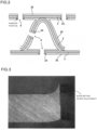
- FIG. 3 is a photograph of a cross section of a burr before the shape adjustment (in other words, a burr immediately after punching).
- Figure 4 is a photograph of the cross section of the burr after the shape adjustment.
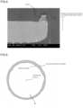
- Figure 5 is a schematic view showing the tip end surface of the burr extending around the hole.
- the burr before the shape adjustment has a sharp tip end; thus, when the catalyst layer is formed on the flat foil (corrugated foil), the burr projects excessively from the catalyst layer. In this case, an exhaust gas collides with the burrs projecting from the catalyst layer, which causes excessive turbulence and increase in pressure loss.
- the tip end surfaces of the burrs 2A, 3A extend in a direction orthogonal to the projecting direction of the burrs.
- the projecting direction of the burrs is thickness direction of the metal foil.
- the term “extend” means that "the tip end surfaces of the burrs 2A, 3A are present and spread in the radial direction from the edges of the holes 8"; and the degree of spreading at each circumferential position is not necessarily uniform.
- the tip end surfaces of the burrs 2A, 3A may be flat or have fine irregularities formed thereon.
- the burrs 2A, 3A are each formed to have a narrow portion 50; and when the width of the tip end surface is defined as P1 and the width of the narrow portion 50 is defined as P2, the magnitude relationship between P1 and P2 is P1 > P2.
- the width means a width in the radial direction of each hole 8.
- the emission control performance of the catalytic converter 1 can be improved by providing the burrs 2A, 3A with small heights.
- the reason is speculated as follows.
- the burrs 2A, 3A having small heights have a small heat capacity and tend to increase in temperature when the exhaust gas flows in.
- these burrs are buried in the catalyst layer 20, accumulated heat is difficult to be deprived by the gas.
- expansion of a catalytic reaction region starting from the burrs occurs although the exhaust gas temperature is low, and thus the catalytic reaction of the honeycomb body 4 as a whole is activated.
- the catalyst supported on and around the burrs acts as reaction sources that determine the start and end of the catalytic reaction, and the catalytic reaction can be activated at an early stage by lowering the temperature of the exhaust gas when the reaction sources generate and disappear.
- the effect by the burrs 2A, 3A is also referred to as the reaction source effect.
- the average height of the burrs 2A, 3A (hereinafter, also referred to as an average height of the burrs L) after the shape adjustment is 0.1 ⁇ m or more and 30 ⁇ m or less, preferably 0.5 ⁇ m or more and 20 ⁇ m or less.
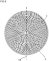
- Figure 6 is a plan view of the catalytic converter 1 as viewed from the axial direction.
- the average height of the burrs L can be found by cutting the converter 1 along a plane including the central axis ("CS" indicated by a dotted line) and measuring the height of every burr appearing on this cut surface using image analysis, then summing up these measurements, and further dividing this summed value by the number of measurements.
- CS central axis
- the burr height can be found from a difference between the foil thickness of the metal foil and the length from one end in the foil thickness direction of the metal foil to the tip end of the burr.
- the burr height of every hole 8 can be found by unwinding the honeycomb body 4, and subsequently imaging the metal foil (the flat foil 2 or the base material of the corrugated foil 3) by an image-size measurement device equipped with an imaging device (CMOS sensor, etc.) to obtain an image along the circumferential direction of the hole 8.
- CMOS sensor imaging device
- the average height of the burrs L can be found by dividing the summed value of the measured burr heights by the number of measurements.
- the burr height of every hole 8 formed in the metal foil (the base material of the flat foil 2 or the corrugated foil 3) can be found using a micrometer.
- the average height of the burrs L can be found by dividing the summed value of the measured burr heights by the number of measurements.
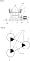
- FIG. 7 is a schematic view of a shape adjustment device as viewed from the feeding side of the metal foil.
- the shape adjustment device 100 includes a drive roller 101, a driven roller 102, a drive motor 103, a transmission mechanism 104, a fixing stand 105, a hydraulic mechanism 106, and a digital indicator 107.
- the drive motor 103 is connected to the drive roller 101 via the transmission mechanism 104, and when the drive motor 103 is operated, driving force of the drive motor 103 is transmitted to the drive roller 101 via the transmission mechanism 104 and thereby the drive roller 101 rotates around a rotation axis L1.
- the driven roller 102 is arranged immediately above the drive roller 101 and is pushed toward the approaching side to the drive roller 101 by the hydraulic mechanism 106. Therefore, the driven roller 102 rotates along with the drive roller 101.
- the metal foil can be slipped in between the drive roller 101 and the driven roller 102 (i.e., a nip part).
- the nip pressure between the drive roller 101 and the driven roller 102 can be adjusted by the hydraulic mechanism 106.
- the nip pressure can be measured by the indicator 107.
- Not-shown guide rollers are arranged upstream of the drive roller 101 and the driven roller 102.
- the hydraulic mechanism 106, a gearbox of the transmission mechanism 104, and the drive motor 103 are fixed onto the fixing stand 105.
- a metal foil having holes with burrs formed by a punching device is prepared, and this foil is fed into the nip part between the drive roller 101 and the driven roller 102 via the not-shown guide rollers.
- the drive roller 101 is brought to rotate clockwise as viewed from the drive motor 103 side, the metal foil is pulled into the nip part between the drive roller 101 and the driven roller 102, and the drive roller 101 (the driven roller 102) comes into contact with the burrs of the metal foil.
- the metal foil for the corrugated foil 3 is conveyed to a corrugated-foil formation step after the shape adjustment by the shape adjustment device 100.
- the corrugated foil 3 can be manufactured by bringing a gear having a shape corresponding to the shape of the corrugated foil to contact with the metal foil to plastically deform this metal foil.
- the shape adjustment method of the burrs 2A, 3A is not limited to the method by the shape adjustment device 100; and for example, in the punching step of the metal foil, the shape adjustment may be performed by arranging a baffle plate to reduce the projections of the burrs.
- the burrs formed at the time of punching abut to the baffle plate to be plastically deformed and thereby the burrs 2A, 3A as shown in Figure 2 can be formed at the edges of the holes 8.
- the thickness of the catalyst layer 20 can be appropriately set in relationship with the average height of the burrs L. That is, as described above, as the amount of projection of the burrs 2A, 3A projecting from the catalyst layer 20 becomes greater, deterioration of the reaction source effect and generation of turbulence become more significant. Therefore, when the thickness of the catalyst layer 20 is set to be equal to or larger than the average height of the burrs L or when the average height of the burrs L is larger than the catalyst layer 20, it is preferable to limit the difference (equivalent to a predetermined amount) between the average height of the burrs L and the thickness of the catalyst layer 20 to 10 ⁇ m or less.
- the average hole diameter of the holes 8 is 0.2 mm or more and 4.0 mm or less.
- the hole diameter of each hole 8 is a diameter thereof.
- the productivity of the catalytic converter 1 would lower.
- the average hole diameter D is greater than 4.0 mm, the sum of edge lengths of the holes 8 (that is, the total edge length of the holes 8 in the entire the honeycomb body 4) becomes smaller, and even by providing the burrs, the total length of the burrs is too short to sufficiently improve the emission control performance.
- the average hole diameter D falls below 1.1 mm, there would be a possibility that the catalyst closes the holes 8 to lower the emission control performance. Accordingly, it is desirable to use a catalyst with a low viscosity in a case where the average hole diameter D is less than 1.1 mm.
- each hole 8 is circular; however, this may be other shapes. Other shapes may include various shapes, such as elliptic or rectangular. In any of these shapes, the hole diameter can be found by converting the area into a circle.
- the hole diameter of each hole 8 can be controlled by a punch diameter and a die diameter of a die.
- the hole diameter of each hole 8 is not necessarily to be the same; however, from the viewpoint of easiness of the machining, etc., it is preferable to manufacture the holes such that the standard deviation ⁇ is 0.001 mm or more and 0.5 mm or less.
- the aperture ratio R is 5% or more and 70% or less, and preferably 20% or more and 70% or less.
- the aperture ratio R is a value calculated as a ratio of a sum total of areas of blackened holes to an entire area surrounded by a triangle as shown in Figure 8 . That is, when a triangle is drawn by connecting the centers of three adjacent holes 8 with lines and an area inside the triangle is defined as an entire area, and areas of parts where the triangle overlaps with the holes 8 are defined as hole areas, a ratio of the hole areas to the entire area is defined as the aperture ratio R.
- the aperture ratio R is decreased to less than 5%, the sum of the edge lengths of the holes 8 becomes too small to sufficiently improve the emission control performance even by providing the burrs.
- the aperture ratio R is more than 70%, the rigidity of the honeycomb body 4 becomes decreased, so that cracks and fractures of the flat foil 2 and the corrugated foil 3 might result in an early failure of the catalytic converter 1.
- the burrs 2A, 3A include burrs having no narrow portions.
- a burr having a narrow portion (that is, the burr shown in Figure 4 ) is referred to as a burr V1
- a burr having no narrow portion (that is, the burr shown in Figure 9 ) is referred to as a burr V2.
- the present inventors have confirmed that the burrs V1 relatively decrease and the burrs V2 relatively increase as the pressure of the roll press increases.
- the predetermined numerical conditions are described again, and these are 0.2 mm ⁇ D ⁇ 4.0 mm, 5% ⁇ R ⁇ 70%, 0.1 ⁇ m ⁇ L ⁇ 30 ⁇ m.
- Figure 9 is a photograph of the burr V2.
- the burr V2 is the same as the burr V1 in that the tip end surface extends in a direction orthogonal to the projecting direction of the burr, and is different from the burr V1 in that the burr V2 has no narrow portion 50.
- the burr height may be found without distinguishing these burrs so as to calculate the average height of the burrs L.
- Figure 10 corresponds to Figure 2 , and is a cross-sectional view of a part of the honeycomb body. Components having common functions to those of the first embodiment are denoted by the same reference numerals.
- the shape adjustment step is not performed, and the average height L of the burrs 2A is set to 0.1 ⁇ m or more and 30 ⁇ m or less. Specifically, by increasing the punching speed of the punching press, the height of the burr 2A can be reduced and the average height L of the burrs 2A can be reduced to 0.1 ⁇ m or more and 30 ⁇ m or less.
- the punching speed of the punching press is preferably 100 mm/sec or more.
- the burr 2A of the present embodiment has a general burr shape with a sharp tip end (i.e., a needle-like tip end), which is different from the burr shape of the first embodiment having the tip end surface extending in the direction orthogonal to the projecting direction of the burr.
- the other configurations are the same as those of the first embodiment; therefore, detailed description thereof is omitted, but the summary is as follows.
- the thickness and the material of the metal foil forming the flat foil 2 and the corrugated foil 3, the catalyst, and the outer mantle 5 are the same as those in the first embodiment. Additionally, the second embodiment is also similar to the first embodiment in that an oxide coating film containing ⁇ -alumina is also formed on the flat foil 2 and the corrugated foil 3 (including the burrs).
- the average height of the burrs L of the burrs 2A, 3A is preferably 0.5 ⁇ m or more and 20 ⁇ m or less, which is the same as that in the first embodiment.
- the method of measuring the average height of the burrs L is also the same as that in the first embodiment.
- the thickness of the catalyst layer 20 is set to be equal to or larger than the average height of the burrs L, or when the average height of the burrs L is larger than the catalyst layer 20, it is preferable to set the difference between the average height of the burrs L and the thickness of the catalyst layer 20 (equivalent to the predetermined amount) to 10 ⁇ m or less.
- the average hole diameter D is 0.2 mm or more and 4.0 mm or less, which is also the same as in the first embodiment.
- the shape of the hole 8 is not limited to circular, as in the first embodiment. It is preferable to manufacture the holes such that the standard deviation ⁇ is 0.001 mm or more and 0.5 mm or less, which is the same as in the first embodiment.
- the aperture ratio R of the holes 8 is 5% or more and 70% less, preferably 20% or more and 70 % or less, which is the same as in the first embodiment.
- an emission control performance, a deterioration of a catalyst and a pressure loss performance were evaluated by variously changing the average height of the burrs L.
- Table 1 shows the result of the evaluation.
- the emission control performance was evaluated by T80°C (i.e., T80°C before aging).
- T80°C is a temperature when CO conversion (%), calculated based on the CO conversion-temperature curve, reaches 80%.
- the CO conversion-temperature curve was obtained by feeding a simulated gas through a catalytic converter at an SV (space velocity) of 100,000 h -1 , gradually heating the simulated gas using a heater from a room temperature, and measuring the CO conversion (%) at each temperature.
- THC propylene, C 3 H 6
- NO 500 ppm
- CO 0.5%
- O 2 1.5%
- H 2 O 10%
- N 2 a balance gas
- the emission control performance of the catalytic converter can be evaluated to be higher with the lowering of T80°C.
- the deterioration of the catalyst was evaluated on the basis of a difference between "T80°C after aging" and "T80°C before aging.”
- the "T80°C after aging” was obtained by heating the catalytic converter under heating conditions including a heating temperature: 980°C and a heating time: 20 hours, cooling the catalytic converter to a room temperature, and then measuring a T80°C by the already described method.
- the deterioration of the catalyst can be evaluated to be lower with a decrease in the difference.
- the pressure loss performance was evaluated by applying a dried 25°C N 2 gas at a flow rate of 0.12 Nm 3 /min and measuring a difference in pressure before and after the catalytic converter.
- a ferritic stainless steel containing Cr: 20 mass%, Al: 5 mass%, and the balance of Fe and unavoidable impurities was used as the metal foil used for the corrugated foil and the flat foil.
- the thickness of the metal foil was 30 ⁇ m.
- Using a punching press holes were formed in a region excluding ends (respective ranges of 5 mm from the exhaust gas inlet side and from the exhaust gas outlet side) of a honeycomb body.
- the average height of the burrs L was controlled by adjusting the punching speed of the punching press without performing a height adjustment through a shape adjustment device.
- the average height of the burrs L was measured by the method described in the embodiment as described with reference to Figure 6 (the same applies to other Embodiment examples described later).
- a region of the metal foil where the holes were formed was imaged from the foil thickness direction of the metal foil, and contours of the holes were converted into data; and thereafter, the hole diameter was found by converting the obtained hole diameter to a circle diameter through computer processing.
- the aperture ratio R was found by the method described in the above embodiment.
- the corrugated foil with a brazing material at appropriate positions was laid on the flat foil coated, and these foils were wound together, and were subjected to heat treatment (brazing), to thereby produce the honeycomb body.
- the diameter of the honeycomb body was 35 mm, and the axial length was 80 mm.
- the cell density was 400 cpsi.
- the honeycomb body thus produced was inserted into an outer mantle and fixed thereto by brazing to provide the catalytic converter.
- the diameter of the catalytic converter was 38 mm, and the axial length was 80 mm.
- a wash-coat liquid containing ceria-zirconia-lanthana-alumina as main components and containing 1.25 g of palladium per 100 g was brought to pass through the honeycomb body, and an excessive wash-coat liquid was removed; and thereafter, the honeycomb body was dried at 180°C for 1 hour and then baked at 500°C for 2 hours to form a catalyst layer with a thickness of 20 ⁇ m on the honeycomb body. It should be noted that the viscosity of the wash-coat liquid was adjusted in use, if necessary, so that none of the holes was closed by the catalyst.
- an oxide coating film was formed by applying the heat treatment to the honeycomb body prior to the formation of a catalyst layer.
- the conditions for the heat treatment were a heating temperature: 900°C and a heating time: two hours. [Table 1] No.
- No. 2 was high in emission control performance (T80°C) by virtue of burrs but experienced a significantly increased deterioration of the catalyst due to the absence of an oxide coating film.
- No. 4 to No. 9 were high in emission control performance (T80°C) by virtue of burrs and the deterioration of the catalyst was also able to be kept low. Additionally, the pressure loss was also able to be maintained at a low value. No.
- the thickness of the oxide coating film and the content of ⁇ -alumina were variously changed and the emission control performance (T80°C), the deterioration of the catalyst, and the pressure loss performance were evaluated.
- the thickness of the oxide coating film and the content of ⁇ -alumina were adjusted by adjusting heat treatment conditions for forming the oxide coating film within ranges of a heating temperature: 1000°C to 1100°C and a heating time: 5 minutes to 20 hours.
- the average height of the burrs L was standardized at 5 ⁇ m by adjusting the punching speed of the punching press without performing a height adjustment through a shape adjustment device as in Example 1.
- the foil thickness of the metal foil was 40 ⁇ m.
- the honeycomb body was 40 mm in diameter and 60 mm in axial length.
- a cell density was 400 cpsi.
- the produced honeycomb body was loaded in an outer mantle and fixed by a brazing treatment to provide a catalytic converter.
- the catalytic converter was 43 mm in diameter and 60 mm in axial length.
- the hole diameter and the aperture ratio were unified at 2 mm and 50%, respectively.
- the other conditions were similar to those of Example 1. [Table 2] No.
- the thickness of the oxide coating film merely reached 0.03 ⁇ m, so that the deterioration of the catalyst increased.
- the thickness of the oxide coating film exceeded 2.0 ⁇ m, so that an evaluation of T80°C after aging was not possible due to the occurrence of foil cracking.
- ⁇ -alumina contained in the oxide coating film was as little as 5 mass%, so that the deterioration of the catalyst increased. It has been found from the present example that the formation of a 0.05 ⁇ m to 2 ⁇ m oxide coating film containing at least 10 mass% ⁇ -alumina makes it possible to effectively reduce the deterioration of the catalyst.
- the average hole diameter D and the aperture ratio R were variously changed and the resulting emission control performance (T80°C), the pressure loss performance, and the deterioration of the catalyst were evaluated.
- the average height of the burrs L was unified at 8 ⁇ m by adjusting the punching speed of the punching press without performing a height adjustment through a shape adjustment device as in Example 1.
- the foil thickness of the metal foil was 50 ⁇ m.
- the honeycomb body was 51 mm in diameter and 120 mm in axial length.
- a cell density was 300 cpsi.
- the produced honeycomb body was loaded in an outer mantle and fixed by a brazing treatment to provide a catalytic converter.
- the catalytic converter was 54 mm in diameter and 120 mm in axial length.
- Table 3 No. Oxide Co ating Film Average height of burrs ( ⁇ m) Hole diameter (mm) Aperture ratio (%) E valuation Note ⁇ -alumina (%) Thickness ( ⁇ m) T80°C 1 Pressure loss (Pa) T80°C after aging 2 Difference between before and after aging °C2-1 24 98 0.9 8 0.2 20 200 48 268 68 Invention Example 16 25 98 0.9 8 0.5 20 197 49 264 67 Invention Example 17 26 98 0.9 8 0.9 20 194 49 254 60 Invention Example 18 27 98 0.9 8 1.1 20 193 51 251 58 Invention Example 19 28 98 0.9 8 20 20 191 52 248 57 Invention Example 20 29 98 0.9 8 3.0 20 193 52 253 60 Invention Example 21 30 98 0.9 8 4.0 20 195 54 258 63 Invention Example 22 31 98 0.9 8 5.0 20 208 55 274 66 Compar
- No. 43 was high in emission control performance (T80°C) by virtue of burrs but experienced a significantly increased deterioration of the catalyst due to the absence of an oxide coating film.
- No. 45 to No. 50 were high in emission control performance (T80°C) by virtue of burrs and the deterioration of the catalyst was also able to be kept low. Additionally, the pressure loss was also able to be maintained at a low value. No.
- the thickness of the oxide coating film merely reached 0.03 ⁇ m, so that the deterioration of the catalyst increased.
- the thickness of the oxide coating film exceeded 2.0 ⁇ m, so that an evaluation of T80°C after aging was not possible due to the occurrence of foil cracking. It has been found that the formation of a 0.05 ⁇ m to 2 ⁇ m oxide coating film containing at least 10 mass% ⁇ -alumina enhances the emission control performance and makes it possible to decrease the pressure loss and the deterioration of the catalyst.
Landscapes
- Chemical & Material Sciences (AREA)
- Engineering & Computer Science (AREA)
- Chemical Kinetics & Catalysis (AREA)
- Materials Engineering (AREA)
- Organic Chemistry (AREA)
- Combustion & Propulsion (AREA)
- Health & Medical Sciences (AREA)
- Environmental & Geological Engineering (AREA)
- Biomedical Technology (AREA)
- Analytical Chemistry (AREA)
- General Chemical & Material Sciences (AREA)
- Oil, Petroleum & Natural Gas (AREA)
- Toxicology (AREA)
- Mechanical Engineering (AREA)
- General Engineering & Computer Science (AREA)
- Catalysts (AREA)
- Exhaust Gas After Treatment (AREA)
- Exhaust Gas Treatment By Means Of Catalyst (AREA)
Abstract



Description
- The present invention relates to a honeycomb-type metal substrate formed by alternately layering a metal flat foil and a metal corrugated foil.
- As a catalyst substrate for removing pollutants from exhaust gas of internal combustion engines of automobiles or the like, there is known a catalytic converter formed by inserting a honeycomb body made of a heat-resistant alloy into an outer mantle made of a heat-resistant alloy. Among catalytic converters, especially in a metal substrate made of a metal foil, a honeycomb body formed by alternately layering a metal flat foil having a thickness of about 50 µm and a corrugated foil obtained by corrugating the flat foil, or a honeycomb body formed by overlapping and spirally winding strip-shaped flat foil and corrugated foil or the like, have been used.
- In recent years, automobile emission regulations have tended to become stricter, and emissions of harmful substances, such as carbon monoxide, hydrocarbons, and nitrogen oxides, especially during a cold start in an emission measurement mode, account for a significant proportion of total emissions; therefore, early activation of the catalyst is required. Hence, there have been proposed various metal substrates in which flat foils and corrugated foils included in metal substrates are subjected to hole-forming processing so as to generate turbulent flows, thereby enhancing the emission control performance.
-
Patent Literature 1 discloses a technique for improving the flow characteristics inside a honeycomb body and improving substance exchanges between a surface and the flow caused by this improvement by appropriately determining the number, the size, and the distribution of holes, thereby improving the emission control performance. -
Patent Literature 2 discloses a catalytic converter excellent in high-temperature durability, mainly including a metal foil in which a plurality of holes are formed and having improved brazing positions.Patent Literature 3 discloses a technique in which in a metal catalyst substrate including a corrugated sheet and a flat sheet in which a plurality of slit holes are formed, annular projections that project from the corrugated sheet and the flat plate at an opening edge of each slit hole are formed, and exhaust gas is caused to collide with the annular projections to cause turbulence, to thereby enhance the emission control performance. -
Patent Literature 4 discloses a catalytic converter for removing pollutants from exhaust gas including a metal honeycomb substrate made by machining a stainless steel foil and a catalyst layer formed on the stainless steel foil, the stainless steel foil containing at least Fe, Cr, and Al, an oxide coating film resulting from oxidation of a stainless steel foil component being formed on a surface of the stainless steel foil, the concentration of Fe contained in the oxide coating film being in a range from 0.1% to 7% in terms of mass% relative to the oxide.Patent Literature 4 also discloses that the movement of Fe in the foil into the catalyst layer is reduced by virtue of the oxide coating film containing Fe and thus the deterioration of the catalyst due to Fe is reduced. - The formation of holes in a metal foil used for a honeycomb body as described in
Patent Literatures 1 to 3 is accompanied by the formation of burrs on the edges of the holes. The burrs, which are unwanted protrusions, are usually removed by a deburring step. -
- Patent Literature 1:
Japanese Patent No. 4975969 - Patent Literature 2:
Japanese Patent No. 5199291 - Patent Literature 3:
Japanese Patent Laid-Open No. 2005-313083 - Patent Literature 4:
Japanese Patent Laid-Open No. 2007-203256 - The present inventors and the like have discovered that emission control performance is improved by leaving a burr formed around a hole. Meanwhile, the present inventors and the like have discovered such a problem that a catalyst around the burr deteriorates due to aging.
- An object of the present invention is to improve the emission control performance of a catalytic converter and reduce a deterioration of a catalyst.
- In order to solve the above-described problem, (A) a honeycomb-type metal substrate formed by alternately layering a metal flat foil and a metal corrugated foil, a plurality of holes being formed in the metal flat foil and the metal corrugated foil, a burr having a small height being formed on an edge of each hole, among the metal flat foil and the metal corrugated foil, at least surfaces of the burrs are covered with an oxide coating film containing α-alumina, the following expressions (1) to (3) being satisfied when an average hole diameter of the plurality of holes is defined as D, an aperture ratio of the holes is defined as R, and an average height of the burrs is defined as L,


- (B) The honeycomb-type metal substrate according to (A), wherein a tip end surface of each burr is formed in a shape extending in a direction orthogonal to a projecting direction of the burr.
- (C) The honeycomb-type metal substrate according to (B), wherein the burrs have narrow portions each having a width smaller than the tip end surface.
- (D) The honeycomb-type metal substrate according to any one of (A) to (C), wherein the average height of the burrs L satisfies the following expression (4),

- (E) A catalytic converter comprising: the honeycomb-type metal substrate according to any one of (A) to (C); and a catalyst layer carried on the metal flat foil and the metal corrugated foil, the average height of the burrs L being smaller than a thickness of the catalyst layer or larger than the thickness of the catalyst layer by a predetermined amount, and the predetermined amount being 10 µm or less.
- (F) A catalytic converter comprising: the honeycomb-type metal substrate according to (D); and a catalyst layer carried on the metal flat foil and the metal corrugated foil, and the average height of the burrs L being smaller than a thickness of the catalyst layer.
- (G) In (A) to (F), the oxide coating film may be in a range from 0.05 µm to 2 µm in thickness and contain at least 10 mass% or more α-alumina.
- The present invention makes it possible to achieve both improving the emission control performance of a catalytic converter and reducing a deterioration of a catalyst.
-
- [
Figure 1] Figure 1 is a perspective view of a catalytic converter. - [
Figure 2] Figure 2 is a cross-sectional view of a part of a honeycomb body. - [
Figure 3] Figure 3 is a photograph of a cross section of a burr before the shape adjustment. - [
Figure 4] Figure 4 is a photograph of the cross section of the burr after the shape adjustment. - [
Figure 5] Figure 5 is a schematic view of a tip end surface of the burr extending around a hole. - [
Figure 6] Figure 6 is a plan view of the catalytic converter for explaining a method of calculating an average height of the burrs L. - [
Figure 7] Figure 7 is a schematic view of a shape adjustment device. - [
Figure 8] Figure 8 is a view for explaining an aperture ratio R. - [
Figure 9] Figure 9 is a photograph of a cross section of a burr (modification) after the shape adjustment. - [
Figure 10] Figure 10 is a cross-sectional view of a part of a honeycomb body (the second embodiment). - Preferred embodiments of the present invention will be described in detail with reference to the drawings.
Figure 1 is a perspective view of acatalytic converter 1, and the axial direction of thecatalytic converter 1 is indicated by a double arrow. Thecatalytic converter 1 includes: a honeycomb body (corresponding to a honeycomb-type metal substrate) 4 formed by spirally winding aflat foil 2 and acorrugated foil 3 into a wound body; and anouter mantle 5 surrounding the outer circumferential surface of thehoneycomb body 4. Note that thehoneycomb body 4 may also be a layered body formed by alternately layering theflat foil 2 and thecorrugated foil 3. Either the wound body or the layered body has a structure in which theflat foil 2 and thecorrugated foil 3 are layered when viewed in a cross section. Hence, the honeycomb-type metal substrate as set forth in the claims includes not only the layered body but also the wound body. - A metal foil made of a heat-resistant alloy may be used for the
flat foil 2 and thecorrugated foil 3. The thickness of the metal foil is preferably 20 µm or more and 100 µm or less. The width of the metal foil is preferably 10 mm or more and 500 mm or less. The size of the metal foil may be changed as appropriate depending on the application of thecatalytic converter 1. Thecorrugated foil 3 may be manufactured by corrugating a metal flat foil, for example. - Here, a stainless steel foil containing aluminum is usable as the heat-resistant alloy. A ferritic stainless steel containing Cr: 20 mass%, Al: 3 to 8 mass%, and the balance of Fe and unavoidable impurities is usable as the stainless steel foil of this type.
Note that the heat-resistant alloy applicable to the present invention is not limited to the aforementioned ferritic stainless steel, and various heat-resistant stainless steels containing Al in the alloy composition may be widely used. That is, the metal foil used for thehoneycomb body 4 usually contains 15 to 25 mass% of Cr and 2 to 8 mass% of Al, and an Fe-18Cr-3Al alloy, an Fe-20Cr-8Al alloy, etc., may also be used as the heat-resistant alloy. - The catalyst can be supported on the metal foil by applying a predetermined wash-coat liquid to the surface of the metal foil of the
honeycomb body 4, and drying and firing this wash-coat liquid. For the wash-coat liquid, for example, a slurry obtained by stirring γ-alumina powder, lanthanum oxide, zirconium oxide, and cerium oxide in an aqueous solution of palladium nitrate may be used. - For example, stainless steel may be used for the
outer mantle 5. The thickness of theouter mantle 5 is preferably 0.5 mm or more and 3 mm or less. The cell density of thehoneycomb body 4 is preferably 100 cells to 600 cells per square inch. - The
catalytic converter 1 is disposed in a not-shown exhaust pipe of a vehicle in such a manner that an exhaust gas can flow in from one end side and can be discharged from the other end side in the axial direction. Reaction of the catalyst supported on thecatalytic converter 1 with the exhaust gas removes pollutants from the exhaust gas having flowed into thecatalytic converter 1. -
Figure 2 is a cross-sectional view of a part of thehoneycomb body 4 cut in the radial direction. Theflat foil 2 and thecorrugated foil 3 each include a plurality ofholes 8 penetrating the foil in the thickness direction. The arrangement of theholes 8 is not particularly limited, for example, in a developed state before being formed into thehoneycomb body 4, the metal foil in which theholes 8 are formed in a checkerboard pattern or a zigzag pattern may be used. Normally, a gas flow in the metal substrate including the metal foil with no holes is a laminar flow. When the metal foil has holes, the Reynolds number is partially increased in portions having the holes, and turbulence is likely to be generated; and as a result, the emission control performance is improved. However, excessive turbulence is not preferable because this causes increase in pressure loss. The present invention suppresses excessive turbulence by limiting the hole diameter and the aperture ratio of theholes 8 to predetermined ranges and by limiting the heights of the burrs to small heights; and deterioration in emission control performance due to the limitation on the turbulence is compensated for by the reaction source (in other words, the fire source) effect of burrs. This will be described later in detail. - A
burr 2A that is buried in acatalyst layer 20 and extends in the circumferential direction is formed on the edge of eachhole 8 of theflat foil 2. Aburr 3A that is buried in thecatalyst layer 20 and extends in the circumferential direction is formed on the edge of eachhole 8 of thecorrugated foil 3. Theburrs - An oxide coating film containing α-alumina is formed on surfaces of the
flat foil 2 and thecorrugated foil 3. The oxide coating film is also formed on surfaces of theburrs flat foil 2 and the corrugated foil 3 (including the surfaces of the burrs) by heating thehoneycomb body 4 under an oxidizing atmosphere having a temperature exceeding 800°C. In a case where the metal foil used as theflat foil 2 and thecorrugated foil 3 is a ferritic stainless steel foil containing Cr: 20 mass%, Al: 3 to 8 mass%, and the balance of Fe and unavoidable impurities , an oxide coating film containing at least 10 mass% or more α-alumina is formed on a surface of the stainless steel foil by applying the above-described oxidation treatment (a heat treatment) to thehoneycomb body 4. The oxide coating film may contain a Cr oxide and an Fe oxide in addition to α-alumina. - A thickness of the oxide coating film is preferably in a range from 0.05 µm to 2 µm. As long as the thickness of the oxide coating film containing at least 10 mass% or more α-alumina is 0.05 µm or more, it is possible to reduce a deterioration of the catalyst due to aging. Reducing the thickness of the oxide coating film to 2 µm or less makes it possible to reduce the lowering of the durability of the
flat foil 2 and thecorrugated foil 3. The thickness of the oxide coating film increases with an increase in content of the aluminum contained in the stainless steel foil. - The structure of the
burrs Figure 3 ,Figure 4, and Figure 5 .Figure 3 is a photograph of a cross section of a burr before the shape adjustment (in other words, a burr immediately after punching).Figure 4 is a photograph of the cross section of the burr after the shape adjustment.Figure 5 is a schematic view showing the tip end surface of the burr extending around the hole. - With reference to
Figure 3 , the burr before the shape adjustment has a sharp tip end; thus, when the catalyst layer is formed on the flat foil (corrugated foil), the burr projects excessively from the catalyst layer. In this case, an exhaust gas collides with the burrs projecting from the catalyst layer, which causes excessive turbulence and increase in pressure loss. - Referring to
Figure 4 , the tip end surfaces of theburrs Figure 5 , the term "extend" means that "the tip end surfaces of theburrs holes 8"; and the degree of spreading at each circumferential position is not necessarily uniform. In addition, the tip end surfaces of theburrs - Further, as shown in
Figure 4 , theburrs narrow portion 50; and when the width of the tip end surface is defined as P1 and the width of thenarrow portion 50 is defined as P2, the magnitude relationship between P1 and P2 is P1 > P2. The width means a width in the radial direction of eachhole 8. - The emission control performance of the
catalytic converter 1 can be improved by providing theburrs burrs catalyst layer 20, accumulated heat is difficult to be deprived by the gas. Hence, expansion of a catalytic reaction region starting from the burrs occurs although the exhaust gas temperature is low, and thus the catalytic reaction of thehoneycomb body 4 as a whole is activated. - In other words, the catalyst supported on and around the burrs acts as reaction sources that determine the start and end of the catalytic reaction, and the catalytic reaction can be activated at an early stage by lowering the temperature of the exhaust gas when the reaction sources generate and disappear. In the following description, the effect by the
burrs burrs - Meanwhile, the present inventors and the like have discovered such a problem that when an exhaust gas is purified using the
catalytic converter 1 with no oxide coating film formed on theflat foil 2 and the corrugated foil 3 (i.e., a catalytic converter out of the scope of the present invention), a deterioration of the catalyst due to aging is increased. As a result of a detailed study about this problem, it has been presumed that the catalyst near theburrs burrs burrs burrs - The average height of the
burrs burrs - When the average height of the burrs L is reduced to less than 0.1 µm, heat energy accumulated in the
burrs burrs catalyst layer 20 come into contact with the gas, to release the heat; therefore, the reaction source effect becomes difficult to be exerted, and the exhaust gas comes into contact with theburrs -
Figure 6 is a plan view of thecatalytic converter 1 as viewed from the axial direction. With reference to this drawing, the average height of the burrs L can be found by cutting theconverter 1 along a plane including the central axis ("CS" indicated by a dotted line) and measuring the height of every burr appearing on this cut surface using image analysis, then summing up these measurements, and further dividing this summed value by the number of measurements. When the measurement is performed, it is desirable to fill gas flow passages (gaps) of thehoneycomb body 4 with resin. The burr height can be found from a difference between the foil thickness of the metal foil and the length from one end in the foil thickness direction of the metal foil to the tip end of the burr. - As another measurement method, the burr height of every
hole 8 can be found by unwinding thehoneycomb body 4, and subsequently imaging the metal foil (theflat foil 2 or the base material of the corrugated foil 3) by an image-size measurement device equipped with an imaging device (CMOS sensor, etc.) to obtain an image along the circumferential direction of thehole 8. In this case, the average height of the burrs L can be found by dividing the summed value of the measured burr heights by the number of measurements. - Further, after the
honeycomb body 4 is unwound, the burr height of everyhole 8 formed in the metal foil (the base material of theflat foil 2 or the corrugated foil 3) can be found using a micrometer. The average height of the burrs L can be found by dividing the summed value of the measured burr heights by the number of measurements. - The adjustment method for adjusting the shapes of the
burrs Figure 7. Figure 7 is a schematic view of a shape adjustment device as viewed from the feeding side of the metal foil. Theshape adjustment device 100 includes adrive roller 101, a drivenroller 102, adrive motor 103, atransmission mechanism 104, a fixingstand 105, ahydraulic mechanism 106, and adigital indicator 107. Thedrive motor 103 is connected to thedrive roller 101 via thetransmission mechanism 104, and when thedrive motor 103 is operated, driving force of thedrive motor 103 is transmitted to thedrive roller 101 via thetransmission mechanism 104 and thereby thedrive roller 101 rotates around a rotation axis L1. - The driven
roller 102 is arranged immediately above thedrive roller 101 and is pushed toward the approaching side to thedrive roller 101 by thehydraulic mechanism 106. Therefore, the drivenroller 102 rotates along with thedrive roller 101. The metal foil can be slipped in between thedrive roller 101 and the driven roller 102 (i.e., a nip part). - The nip pressure between the
drive roller 101 and the drivenroller 102 can be adjusted by thehydraulic mechanism 106. The nip pressure can be measured by theindicator 107. Not-shown guide rollers are arranged upstream of thedrive roller 101 and the drivenroller 102. Thehydraulic mechanism 106, a gearbox of thetransmission mechanism 104, and thedrive motor 103 are fixed onto the fixingstand 105. - In the above-described configuration, a metal foil having holes with burrs formed by a punching device is prepared, and this foil is fed into the nip part between the
drive roller 101 and the drivenroller 102 via the not-shown guide rollers. Thedrive roller 101 is brought to rotate clockwise as viewed from thedrive motor 103 side, the metal foil is pulled into the nip part between thedrive roller 101 and the drivenroller 102, and the drive roller 101 (the driven roller 102) comes into contact with the burrs of the metal foil. - When the
drive roller 101 and the drivenroller 102 are further brought to rotate, the burrs are pressed and crushed by these rollers to form thenarrow portions 50 of theburrs burrs corrugated foil 3 is conveyed to a corrugated-foil formation step after the shape adjustment by theshape adjustment device 100. In the corrugated-foil formation step, for example, thecorrugated foil 3 can be manufactured by bringing a gear having a shape corresponding to the shape of the corrugated foil to contact with the metal foil to plastically deform this metal foil. - The shape adjustment method of the
burrs shape adjustment device 100; and for example, in the punching step of the metal foil, the shape adjustment may be performed by arranging a baffle plate to reduce the projections of the burrs. In this case, the burrs formed at the time of punching abut to the baffle plate to be plastically deformed and thereby theburrs Figure 2 can be formed at the edges of theholes 8. - The thickness of the
catalyst layer 20 can be appropriately set in relationship with the average height of the burrs L. That is, as described above, as the amount of projection of theburrs catalyst layer 20 becomes greater, deterioration of the reaction source effect and generation of turbulence become more significant. Therefore, when the thickness of thecatalyst layer 20 is set to be equal to or larger than the average height of the burrs L or when the average height of the burrs L is larger than thecatalyst layer 20, it is preferable to limit the difference (equivalent to a predetermined amount) between the average height of the burrs L and the thickness of thecatalyst layer 20 to 10 µm or less. - Here, when the average hole diameter of the
holes 8 is defined as D, the average hole diameter D is 0.2 mm or more and 4.0 mm or less. The hole diameter of eachhole 8 is a diameter thereof. When the average hole diameter D falls below 0.2 mm, the productivity of thecatalytic converter 1 would lower.
When the average hole diameter D is greater than 4.0 mm, the sum of edge lengths of the holes 8 (that is, the total edge length of theholes 8 in the entire the honeycomb body 4) becomes smaller, and even by providing the burrs, the total length of the burrs is too short to sufficiently improve the emission control performance. It should be noted that if the average hole diameter D falls below 1.1 mm, there would be a possibility that the catalyst closes theholes 8 to lower the emission control performance. Accordingly, it is desirable to use a catalyst with a low viscosity in a case where the average hole diameter D is less than 1.1 mm. - In the above-described embodiment, it is exemplified that the shape of each
hole 8 is circular; however, this may be other shapes. Other shapes may include various shapes, such as elliptic or rectangular. In any of these shapes, the hole diameter can be found by converting the area into a circle. - The hole diameter of each
hole 8 can be controlled by a punch diameter and a die diameter of a die. The hole diameter of eachhole 8 is not necessarily to be the same; however, from the viewpoint of easiness of the machining, etc., it is preferable to manufacture the holes such that the standard deviation σ is 0.001 mm or more and 0.5 mm or less. - When the aperture ratio of the
holes 8 is defined as R, the aperture ratio R is 5% or more and 70% or less, and preferably 20% or more and 70% or less. Here, the aperture ratio R is a value calculated as a ratio of a sum total of areas of blackened holes to an entire area surrounded by a triangle as shown inFigure 8 . That is, when a triangle is drawn by connecting the centers of threeadjacent holes 8 with lines and an area inside the triangle is defined as an entire area, and areas of parts where the triangle overlaps with theholes 8 are defined as hole areas, a ratio of the hole areas to the entire area is defined as the aperture ratio R. - When the aperture ratio R is decreased to less than 5%, the sum of the edge lengths of the
holes 8 becomes too small to sufficiently improve the emission control performance even by providing the burrs. When the aperture ratio R is more than 70%, the rigidity of thehoneycomb body 4 becomes decreased, so that cracks and fractures of theflat foil 2 and thecorrugated foil 3 might result in an early failure of thecatalytic converter 1. - Modifications of the present invention will be described. In the
catalytic converter 1 of the present modification, theburrs - In the present modification, for convenience of explanation, a burr having a narrow portion (that is, the burr shown in
Figure 4 ) is referred to as a burr V1, and a burr having no narrow portion (that is, the burr shown inFigure 9 ) is referred to as a burr V2. - The present inventors have confirmed that the burrs V1 relatively decrease and the burrs V2 relatively increase as the pressure of the roll press increases.
- Also in the
catalytic converter 1 where the burrs V1 and V2 are mixed, it is possible to obtain the same effect as that of the first embodiment, such as the reaction source effect, by satisfying the predetermined numerical conditions. - Although already having been described in the first embodiment, the predetermined numerical conditions are described again, and these are 0.2 mm ≤ D ≤ 4.0 mm, 5% ≤ R ≤ 70%, 0.1 µm ≤ L ≤ 30 µm.
-
Figure 9 is a photograph of the burr V2. With reference to this drawing, the burr V2 is the same as the burr V1 in that the tip end surface extends in a direction orthogonal to the projecting direction of the burr, and is different from the burr V1 in that the burr V2 has nonarrow portion 50. - This might be presumed that when a needle-like burr is pressed by the
shape adjustment device 100 while the hydraulic pressure of thehydraulic mechanism 106 is increased, a narrow portion like that of the burr V1 is first formed, and when the pressure is further increased, the narrow portion is crushed into a step-like burr having nonarrow portion 50, as shown inFigure 9 . - In the case in which the burrs V1 and V2 are mixed as in the present embodiment, the burr height may be found without distinguishing these burrs so as to calculate the average height of the burrs L.
- The second embodiment of the present invention will be described with reference to
Figure 10. Figure 10 corresponds toFigure 2 , and is a cross-sectional view of a part of the honeycomb body. Components having common functions to those of the first embodiment are denoted by the same reference numerals. In theburrs burrs 2A is set to 0.1 µm or more and 30 µm or less. Specifically, by increasing the punching speed of the punching press, the height of theburr 2A can be reduced and the average height L of theburrs 2A can be reduced to 0.1 µm or more and 30 µm or less. The punching speed of the punching press is preferably 100 mm/sec or more. - Therefore, the
burr 2A of the present embodiment has a general burr shape with a sharp tip end (i.e., a needle-like tip end), which is different from the burr shape of the first embodiment having the tip end surface extending in the direction orthogonal to the projecting direction of the burr. The other configurations are the same as those of the first embodiment; therefore, detailed description thereof is omitted, but the summary is as follows. - The thickness and the material of the metal foil forming the
flat foil 2 and thecorrugated foil 3, the catalyst, and theouter mantle 5 are the same as those in the first embodiment. Additionally, the second embodiment is also similar to the first embodiment in that an oxide coating film containing α-alumina is also formed on theflat foil 2 and the corrugated foil 3 (including the burrs). - The average height of the burrs L of the
burrs - As the amount of projection of the
burrs catalyst layer 20 becomes greater, deterioration of the reaction source effect and generation of turbulence become more significant. Therefore, when the thickness of thecatalyst layer 20 is set to be equal to or larger than the average height of the burrs L, or when the average height of the burrs L is larger than thecatalyst layer 20, it is preferable to set the difference between the average height of the burrs L and the thickness of the catalyst layer 20 (equivalent to the predetermined amount) to 10 µm or less. - The average hole diameter D is 0.2 mm or more and 4.0 mm or less, which is also the same as in the first embodiment. The shape of the
hole 8 is not limited to circular, as in the first embodiment. It is preferable to manufacture the holes such that the standard deviation σ is 0.001 mm or more and 0.5 mm or less, which is the same as in the first embodiment. The aperture ratio R of theholes 8 is 5% or more and 70% less, preferably 20% or more and 70 % or less, which is the same as in the first embodiment. - As described above, by providing the
burrs - In the present Embodiment example, an emission control performance, a deterioration of a catalyst and a pressure loss performance were evaluated by variously changing the average height of the burrs L. Table 1 shows the result of the evaluation. The emission control performance was evaluated by T80°C (i.e., T80°C before aging). T80°C is a temperature when CO conversion (%), calculated based on the CO conversion-temperature curve, reaches 80%. The CO conversion-temperature curve was obtained by feeding a simulated gas through a catalytic converter at an SV (space velocity) of 100,000 h-1, gradually heating the simulated gas using a heater from a room temperature, and measuring the CO conversion (%) at each temperature. Using THC (propylene, C3H6): 550 ppm (1650 ppmC), NO: 500 ppm, CO: 0.5%, O2: 1.5%, H2O: 10%, N2: a balance gas, a diesel exhaust gas was simulated. The emission control performance of the catalytic converter can be evaluated to be higher with the lowering of T80°C.
- The deterioration of the catalyst was evaluated on the basis of a difference between "T80°C after aging" and "T80°C before aging." The "T80°C after aging" was obtained by heating the catalytic converter under heating conditions including a heating temperature: 980°C and a heating time: 20 hours, cooling the catalytic converter to a room temperature, and then measuring a T80°C by the already described method. The deterioration of the catalyst can be evaluated to be lower with a decrease in the difference.
- The pressure loss performance was evaluated by applying a dried 25°C N2 gas at a flow rate of 0.12 Nm3/min and measuring a difference in pressure before and after the catalytic converter.
- As the metal foil used for the corrugated foil and the flat foil, a ferritic stainless steel containing Cr: 20 mass%, Al: 5 mass%, and the balance of Fe and unavoidable impurities was used. The thickness of the metal foil was 30 µm. Using a punching press, holes were formed in a region excluding ends (respective ranges of 5 mm from the exhaust gas inlet side and from the exhaust gas outlet side) of a honeycomb body. The average height of the burrs L was controlled by adjusting the punching speed of the punching press without performing a height adjustment through a shape adjustment device. The average height of the burrs L was measured by the method described in the embodiment as described with reference to
Figure 6 (the same applies to other Embodiment examples described later). - A region of the metal foil where the holes were formed was imaged from the foil thickness direction of the metal foil, and contours of the holes were converted into data; and thereafter, the hole diameter was found by converting the obtained hole diameter to a circle diameter through computer processing. The aperture ratio R was found by the method described in the above embodiment.
- After the metal foil obtained by the above-described processing was corrugated into a corrugated foil, the corrugated foil with a brazing material at appropriate positions was laid on the flat foil coated, and these foils were wound together, and were subjected to heat treatment (brazing), to thereby produce the honeycomb body. The diameter of the honeycomb body was 35 mm, and the axial length was 80 mm. The cell density was 400 cpsi. The honeycomb body thus produced was inserted into an outer mantle and fixed thereto by brazing to provide the catalytic converter. The diameter of the catalytic converter was 38 mm, and the axial length was 80 mm.
- A wash-coat liquid containing ceria-zirconia-lanthana-alumina as main components and containing 1.25 g of palladium per 100 g was brought to pass through the honeycomb body, and an excessive wash-coat liquid was removed; and thereafter, the honeycomb body was dried at 180°C for 1 hour and then baked at 500°C for 2 hours to form a catalyst layer with a thickness of 20 µm on the honeycomb body.
It should be noted that the viscosity of the wash-coat liquid was adjusted in use, if necessary, so that none of the holes was closed by the catalyst. - As for Nos. 3 to 10, an oxide coating film was formed by applying the heat treatment to the honeycomb body prior to the formation of a catalyst layer. The conditions for the heat treatment were a heating temperature: 900°C and a heating time: two hours.
[Table 1] No. Oxide Co ating Film Average height of burrs (µm) Hole diameter (mm) Aperture ratio (%) E valuation Note α-alumina (%) Thickness (µm) T80° C ①Pressure loss (Pa) T80°C after aging ② Difference between before and after aging °C②-① 1 0 0 0 0.9 40 195 87 270 75 Comparative Exam ple 12 0 0 5 0.9 40 184 87 269 85 Comparative Exam ple 23 80 0.3 0 0.9 40 195 87 270 75 Comparative Example 3 4 80 0.3 0.1 0.9 40 190 87 259 69 Invention Example 1 5 80 0.3 1 0.9 40 187 87 252 65 Invention Example 2 6 80 0.3 5 0.9 40 184 87 248 64 Invention Example 3 7 80 0.3 10 0.9 40 183 87 247 64 Invention Example 4 8 80 0.3 20 0.9 40 186 87 250 64 Invention Example 5 9 80 0.3 30 0.9 40 190 93 255 65 Invention Example 6 10 80 0.3 40 0.9 40 194 110 264 70 Comparative Example 4 - No. 1 and No. 3, which had no burr, were low in emission control performance (T80°C). No. 2 was high in emission control performance (T80°C) by virtue of burrs but experienced a significantly increased deterioration of the catalyst due to the absence of an oxide coating film. No. 4 to No. 9 were high in emission control performance (T80°C) by virtue of burrs and the deterioration of the catalyst was also able to be kept low. Additionally, the pressure loss was also able to be maintained at a low value. No. 10 had burrs considerably projecting from the catalyst layer (projecting from the catalyst layer by 20 µm), so that the pressure loss increased due to the generation of a turbulent flow and the emission control performance (T80°C) deteriorated due to the lowering of the reaction source effect.
- The thickness of the oxide coating film and the content of α-alumina were variously changed and the emission control performance (T80°C), the deterioration of the catalyst, and the pressure loss performance were evaluated. The thickness of the oxide coating film and the content of α-alumina were adjusted by adjusting heat treatment conditions for forming the oxide coating film within ranges of a heating temperature: 1000°C to 1100°C and a heating time: 5 minutes to 20 hours. The average height of the burrs L was standardized at 5 µm by adjusting the punching speed of the punching press without performing a height adjustment through a shape adjustment device as in Example 1. The foil thickness of the metal foil was 40 µm. The honeycomb body was 40 mm in diameter and 60 mm in axial length. A cell density was 400 cpsi. The produced honeycomb body was loaded in an outer mantle and fixed by a brazing treatment to provide a catalytic converter. The catalytic converter was 43 mm in diameter and 60 mm in axial length. The hole diameter and the aperture ratio were unified at 2 mm and 50%, respectively. The other conditions were similar to those of Example 1.
[Table 2] No. Oxide Co ating Film Average height of burrs (µm) Hole diameter (mm) Aperture ratio (%) E valuation Note α-alumina (%) Thickness (µm) T80° C ①Pressure loss (Pa) T80°C after aging ② Difference between before and after aging °C②-① 11 0 0 5 2 50 190 52 265 75 Comparative Example 5 12 80 0.03 5 2 50 191 52 266 75 Comparative Example 6 13 80 0.05 5 2 50 190 52 260 70 Invention Example 7 14 80 0.1 5 2 50 190 52 255 65 Invention Example 8 15 80 0.5 5 2 50 190 52 254 64 Invention Example 9 16 80 10 5 2 50 191 52 254 63 Invention Example 10 17 80 20 5 2 50 190 52 254 64 Invention Example 11 18 80 2.5 5 2 50 190 52 Foil Cracking Comparative Example 7 19 5 0.5 5 2 50 190 52 266 76 Comparative Example 8 20 10 0.5 5 2 50 190 52 260 70 Invention Example 12 21 30 0.5 5 2 50 191 52 256 65 Invention Example 13 22 50 0.5 5 2 50 190 52 253 63 Invention Example 14 23 100 0.5 5 2 50 190 52 252 62 Invention Example 15 - Regarding No. 12, the thickness of the oxide coating film merely reached 0.03 µm, so that the deterioration of the catalyst increased. Regarding No. 18, the thickness of the oxide coating film exceeded 2.0 µm, so that an evaluation of T80°C after aging was not possible due to the occurrence of foil cracking. Regarding No. 19, α-alumina contained in the oxide coating film was as little as 5 mass%, so that the deterioration of the catalyst increased. It has been found from the present example that the formation of a 0.05 µm to 2 µm oxide coating film containing at least 10 mass% α-alumina makes it possible to effectively reduce the deterioration of the catalyst.
- In the present example, the average hole diameter D and the aperture ratio R were variously changed and the resulting emission control performance (T80°C), the pressure loss performance, and the deterioration of the catalyst were evaluated. The average height of the burrs L was unified at 8 µm by adjusting the punching speed of the punching press without performing a height adjustment through a shape adjustment device as in Example 1. The foil thickness of the metal foil was 50 µm. The honeycomb body was 51 mm in diameter and 120 mm in axial length. A cell density was 300 cpsi. The produced honeycomb body was loaded in an outer mantle and fixed by a brazing treatment to provide a catalytic converter.
- The catalytic converter was 54 mm in diameter and 120 mm in axial length.
[Table 3] No. Oxide Co ating Film Average height of burrs (µm) Hole diameter (mm) Aperture ratio (%) E valuation Note α-alumina (%) Thickness (µm) T80°C ① Pressure loss (Pa) T80°C after aging ② Difference between before and after aging °C②-① 24 98 0.9 8 0.2 20 200 48 268 68 Invention Example 16 25 98 0.9 8 0.5 20 197 49 264 67 Invention Example 17 26 98 0.9 8 0.9 20 194 49 254 60 Invention Example 18 27 98 0.9 8 1.1 20 193 51 251 58 Invention Example 19 28 98 0.9 8 20 20 191 52 248 57 Invention Example 20 29 98 0.9 8 3.0 20 193 52 253 60 Invention Example 21 30 98 0.9 8 4.0 20 195 54 258 63 Invention Example 22 31 98 0.9 8 5.0 20 208 55 274 66 Comparative Example 9 32 98 0.9 8 2.5 3 208 48 277 69 Comparative Example 10 33 98 0.9 8 2.5 5 200 50 269 69 Invention Example 23 34 98 0.9 8 2.5 10 196 51 261 65 Invention Example 24 35 98 0.9 8 2.5 20 190 53 254 64 Invention Example 25 36 98 0.9 8 2.5 30 189 54 252 63 Invention Example 26 37 98 0.9 8 2.5 40 185 54 247 62 Invention Example 27 38 98 0.9 8 25 50 185 56 247 62 Invention Example 28 39 98 0.9 8 25 60 184 59 249 65 Invention Example 29 40 98 0.9 8 2.5 70 182 60 251 69 Invention Example 30 41 98 0.9 8 2.5 80 182 61 Foil Cracking Comparative Example 11 - Referring to Nos. 24 to 30, it has been found that providing burrs makes it possible to secure a desired emission control performance (T80°C) even though the average hole diameter D is small. Regarding No. 31, it was not possible to improve the emission control performance (T80°C) due to the excessively large average hole diameter D and the short total length of the burrs. Regarding No. 32, it was not possible to improve the emission control performance due to the excessively small aperture ratio and the short total length of the burrs. Regarding No. 41, the aperture ratio exceeded 70% and foil cracking of the metal foil was seen after aging, so that the deterioration of the catalyst was not evaluated.
- In the present example, a test was performed under conditions similar to those of Example 1 except that the average height of the burrs L was adjusted using a shape adjustment device. It should be noted that as for Nos. 45 to 46, it was observed that 30%, approximately, were the burrs V2 and the others were the burrs V1 having narrow portions. As for Nos. 46 to 51, the burrs V1 having narrow portions were dominant.
[Table 4] No. Oxide Coating Film Average height of burrs (µm) Hole diameter (mm) Aperture ratio (%) Evaluation Note α-alumina (%) Thickness (µm) T80° C ①Pressure loss (Pa) T80°C after aging ② Difference between before and after aging °C②-① 42 0 0 0 0.9 40 195 87 270 75 Comparative Example 12 43 0 0 5 0.9 40 182 87 267 85 Comparative Example 13 44 80 0.3 0 0.9 40 195 87 270 75 Comparative Example 14 45 80 0.3 0.1 0.9 40 188 87 257 69 Invention Example 31 46 80 0.3 1 0.9 40 185 87 250 65 Invention Example 32 47 80 0.3 5 0.9 40 182 87 246 64 Invention Example 33 48 80 0.3 10 0.9 40 181 87 245 64 Invention Example 34 49 80 0.3 20 0.9 40 184 87 248 64 Invention Example 35 50 80 0.3 30 0.9 40 188 92 253 65 Invention Example 36 51 80 0.3 40 0.9 40 194 110 264 70 Comparative Example 15 - No. 42 and No. 44, which had no burr, were low in emission control performance (T80°C). No. 43 was high in emission control performance (T80°C) by virtue of burrs but experienced a significantly increased deterioration of the catalyst due to the absence of an oxide coating film. No. 45 to No. 50 were high in emission control performance (T80°C) by virtue of burrs and the deterioration of the catalyst was also able to be kept low. Additionally, the pressure loss was also able to be maintained at a low value. No. 51 had burrs considerably projecting from the catalyst layer (projecting from the catalyst layer by 20 µm), so that the pressure loss increased due to the generation of a turbulent flow and the emission control performance (T80°C) deteriorated due to the lowering of the reaction source effect.
- In the present example, a test was performed under conditions similar to those of Example 2 except that the average height of the burrs L was adjusted using a shape adjustment device.
[Table 5] No. Oxide Coating Film Average height of burrs (µm) Hole diameter (mm) Aperture ratio (%) Evaluation Note α-alumina (%) Thickness (µm) T80° C ①Pressure loss (Pa) T80°C after aging ② Difference between before and after aging °C②-① 52 0 0 5 2 50 188 52 263 75 Comparative Example 16 53 80 0.03 5 2 50 188 52 263 75 Comparative Example 17 54 80 0.05 5 2 50 188 52 258 70 Invention Example 37 55 80 0.1 5 2 50 189 52 254 65 Invention Example 38 56 80 0.5 5 2 50 188 52 252 64 Invention Example 39 57 80 1.0 5 2 50 187 52 250 63 Invention Example 40 58 80 20 5 2 50 188 52 252 64 Invention Example 41 59 80 2.5 5 2 50 188 52 Foil Cracking Com parative Exam ple 18 60 5 0.5 5 2 50 188 52 264 76 Comparative Example 19 61 10 0.5 5 2 50 187 52 257 70 Invention Example 42 62 30 0.5 5 2 50 188 52 253 65 Invention Example 43 63 50 0.5 5 2 50 187 52 250 63 Invention Example 44 64 100 0.5 5 2 50 188 52 250 62 Invention Example 45 - Regarding No. 53, the thickness of the oxide coating film merely reached 0.03 µm, so that the deterioration of the catalyst increased. Regarding No. 59, the thickness of the oxide coating film exceeded 2.0 µm, so that an evaluation of T80°C after aging was not possible due to the occurrence of foil cracking. It has been found that the formation of a 0.05 µm to 2 µm oxide coating film containing at least 10 mass% α-alumina enhances the emission control performance and makes it possible to decrease the pressure loss and the deterioration of the catalyst.
- In the present example, a test was performed under conditions similar to those of Example 3 except that the average height of the burrs L was adjusted using a shape adjustment device.
[Table 6] No. Oxide coating film Average height of burrs (µm) Hole diameter (mm) Aperture ratio (%) Evaluation Note α-alumina (%) Thickness (µm) T80 °C ① Pressure loss (Pa) T80°C after aging ② Difference between before and after aging °C②-① 65 98 0.9 8 0.2 20 198 48 266 68 Invention Example 46 66 98 0.9 8 0.5 20 195 48 262 67 Invention Example 47 67 98 0.9 8 0.9 20 192 49 252 60 Invention Example 48 68 98 0.9 8 1.1 20 191 50 249 58 Invention Example 49 69 98 0.9 8 20 20 189 52 246 57 Invention Example 50 70 98 0.9 8 3.0 20 191 53 251 60 Invention Example 51 71 98 0.9 8 4.0 20 193 54 256 63 Invention Example 52 72 98 0.9 8 5.0 20 206 55 272 66 Comparative Example 20 73 98 0.9 8 2.5 3 206 48 275 69 Comparative Example 21 74 98 0.9 8 2.5 5 198 49 267 69 Invention Example 53 75 98 0.9 8 2.5 10 194 51 259 65 Invention Example 54 76 98 0.9 8 2.5 20 188 52 252 64 Invention Example 55 77 98 0.9 8 2.5 30 187 52 250 63 Invention Example 56 78 98 0.9 8 2.5 40 183 54 245 62 Invention Example 57 79 98 0.9 8 2.5 50 183 55 245 62 Invention Example 58 80 98 0.9 8 2.5 60 182 58 247 65 Invention Example 59 81 98 0.9 8 2.5 70 181 59 250 69 Invention Example 60 82 98 0.9 8 2.5 80 181 61 Foil Cracking Comparative Example 22 - Referring to Nos. 65 to 71, it has been found that providing burrs makes it possible to secure a desired emission control performance (T80°C) even though the average hole diameter D is small. Regarding No. 72, it was not possible to improve the emission control performance (T80°C) due to the excessively large average hole diameter D and the short total length of the burrs. Regarding No. 73, it was not possible to improve the emission control performance (T80°C) due to the excessively small aperture ratio and the short total length of the burrs. Regarding No. 82, the aperture ratio exceeded 70% and foil cracking of the metal foil was seen after aging, so that the deterioration of the catalyst was not evaluated.
-
- 1
- catalytic converter
- 2
- flat foil
- 3
- corrugated foil
- 4
- honeycomb body
Claims (8)
- A honeycomb-type metal substrate formed by alternately layering a metal flat foil and a metal corrugated foil,a plurality of holes being formed in the metal flat foil and the metal corrugated foil,a burr having a small height being formed on an edge of each hole,among the metal flat foil and the metal corrugated foil, at least surfaces of the burrs are covered with an oxide coating film containing α-alumina,the following expressions (1) to (3) being satisfied when an average hole diameter of the plurality of holes is defined as D, an aperture ratio of the holes is defined as R, and an average height of the burrs is defined as L,


- The honeycomb-type metal substrate according to claim 1, wherein
a tip end surface of each burr is formed in a shape extending in a direction orthogonal to a projecting direction of the burr. - The honeycomb-type metal substrate according to claim 2, wherein
the burrs have narrow portions each having a width smaller than the tip end surface. - The honeycomb-type metal substrate according to any one of claims 1 to 3, wherein
the average height of the burrs L satisfies the following expression (4),
- A catalytic converter comprising:the honeycomb-type metal substrate according to any one of claims 1 to 3; anda catalyst layer carried on the metal flat foil and the metal corrugated foil,the average height of the burrs L being smaller than a thickness of the catalyst layer or larger than the thickness of the catalyst layer by a predetermined amount, andthe predetermined amount being 10 µm or less.
- A catalytic converter comprising:the honeycomb-type metal substrate according to claim 4; anda catalyst layer carried on the metal flat foil and the metal corrugated foil, andthe average height of the burrs L being smaller than a thickness of the catalyst layer.
- The honeycomb-type metal substrate according to any one of claims 1 to 4, wherein the oxide coating film is in a range from 0.05 µm to 2 µm in thickness and contains at least 10 mass% or more α-alumina.
- The catalytic converter according to claim 5 or 6,
wherein the oxide coating film is in a range from 0.05 µm to 2 µm in thickness and contains at least 10 mass% or more α-alumina.
Applications Claiming Priority (2)
| Application Number | Priority Date | Filing Date | Title |
|---|---|---|---|
| JP2021151781A JP7033689B1 (en) | 2021-09-17 | 2021-09-17 | Honeycomb type metal carrier and catalytic converter |
| PCT/JP2022/020024 WO2023042479A1 (en) | 2021-09-17 | 2022-05-12 | Honeycomb type metal carrier and catalytic converter |
Publications (3)
| Publication Number | Publication Date |
|---|---|
| EP4368286A1 true EP4368286A1 (en) | 2024-05-15 |
| EP4368286A4 EP4368286A4 (en) | 2024-06-26 |
| EP4368286B1 EP4368286B1 (en) | 2025-01-01 |
Family
ID=81213088
Family Applications (1)
| Application Number | Title | Priority Date | Filing Date |
|---|---|---|---|
| EP22869630.8A Active EP4368286B1 (en) | 2021-09-17 | 2022-05-12 | Honeycomb-type metal substrate and catalytic converter |
Country Status (4)
| Country | Link |
|---|---|
| EP (1) | EP4368286B1 (en) |
| JP (1) | JP7033689B1 (en) |
| CN (1) | CN117858760B (en) |
| WO (1) | WO2023042479A1 (en) |
Families Citing this family (1)
| Publication number | Priority date | Publication date | Assignee | Title |
|---|---|---|---|---|
| JP7129535B1 (en) | 2021-11-05 | 2022-09-01 | 日鉄ケミカル&マテリアル株式会社 | Honeycomb type metal carrier and catalytic converter |
Family Cites Families (21)
| Publication number | Priority date | Publication date | Assignee | Title |
|---|---|---|---|---|
| CN1004992B (en) * | 1986-07-30 | 1989-08-16 | 北京工业大学 | Method for preparing rare earth metal composite oxide/alloy honeycomb catalyst |
| JP2830524B2 (en) * | 1991-07-30 | 1998-12-02 | トヨタ自動車株式会社 | Catalyst carrier structure of catalytic converter for internal combustion engine |
| JP4236724B2 (en) * | 1998-03-12 | 2009-03-11 | 日新製鋼株式会社 | Metal filter for diesel engine |
| JP2002177793A (en) * | 2000-10-02 | 2002-06-25 | Nippon Soken Inc | Ceramic carrier and ceramic catalyst body |
| JP3573708B2 (en) * | 2000-11-22 | 2004-10-06 | 株式会社オーデン | Diesel particulate removal equipment |
| CN1320260C (en) | 2002-08-16 | 2007-06-06 | 排放技术有限公司 | Metal honeycomb body consisting of at least partially perforated sheet metal layers |
| JP2005081306A (en) * | 2003-09-10 | 2005-03-31 | Calsonic Kansei Corp | Catalyst carrier made of metal |
| JP2005313083A (en) | 2004-04-28 | 2005-11-10 | Calsonic Kansei Corp | Catalyst carrier made of metal |
| JP4762506B2 (en) | 2004-05-26 | 2011-08-31 | 新日鉄マテリアルズ株式会社 | Honeycomb body and manufacturing method thereof |
| JP2006142138A (en) | 2004-11-16 | 2006-06-08 | Calsonic Kansei Corp | Metal carrier |
| JP2007023997A (en) * | 2005-07-21 | 2007-02-01 | Hino Motors Ltd | Exhaust purification device |
| JP5019753B2 (en) | 2006-02-03 | 2012-09-05 | 新日鉄マテリアルズ株式会社 | Exhaust gas purification catalytic converter |
| KR100853533B1 (en) * | 2007-02-02 | 2008-08-21 | (주)모두액세스 | Metal catalyst carrier |
| JP5279284B2 (en) | 2008-01-30 | 2013-09-04 | 株式会社キャタラー | Punching metal carrier catalyst for exhaust gas purification |
| JP5199291B2 (en) | 2010-02-03 | 2013-05-15 | 新日鉄住金マテリアルズ株式会社 | Catalyst carrier |
| DE102011119517B4 (en) * | 2011-11-25 | 2017-02-09 | Oberland Mangold Gmbh | Honeycomb body and method for its production |
| JP6396748B2 (en) * | 2014-10-02 | 2018-09-26 | 新日鉄住金マテリアルズ株式会社 | Catalyst support substrate, catalyst support, catalyst support substrate manufacturing method, and catalyst support manufacturing method |
| CN107735176B (en) * | 2016-01-08 | 2020-02-21 | 日铁化学材料株式会社 | Catalyst-supported honeycomb body and catalyst converter |
| EP3590599B1 (en) * | 2017-02-28 | 2021-12-01 | NIPPON STEEL Chemical & Material Co., Ltd. | Honeycomb substrate for catalyst support, and catalytic converter for exhaust gas purification |
| JP6340101B1 (en) * | 2017-02-28 | 2018-06-06 | 新日鉄住金マテリアルズ株式会社 | Catalyst support substrate and catalyst support |
| JP7106565B2 (en) * | 2017-10-27 | 2022-07-26 | 株式会社キャタラー | Exhaust gas purifier using metal base material and manufacturing method thereof |
-
2021
- 2021-09-17 JP JP2021151781A patent/JP7033689B1/en active Active
-
2022
- 2022-05-12 EP EP22869630.8A patent/EP4368286B1/en active Active
- 2022-05-12 CN CN202280053604.5A patent/CN117858760B/en active Active
- 2022-05-12 WO PCT/JP2022/020024 patent/WO2023042479A1/en not_active Ceased
Also Published As
| Publication number | Publication date |
|---|---|
| EP4368286B1 (en) | 2025-01-01 |
| JP2023043990A (en) | 2023-03-30 |
| CN117858760A (en) | 2024-04-09 |
| CN117858760B (en) | 2025-02-11 |
| JP7033689B1 (en) | 2022-03-10 |
| EP4368286A4 (en) | 2024-06-26 |
| WO2023042479A1 (en) | 2023-03-23 |
Similar Documents
| Publication | Publication Date | Title |
|---|---|---|
| DE69729597T2 (en) | Heat-resistant foil made of high-alloy, ferritic steel | |
| CN100418630C (en) | Microstructure relieved of notching | |
| KR101365825B1 (en) | Exhaust gas cleaning component having a deflection surface and method for production thereof | |
| US6142362A (en) | Sheet metal layers of a layer-like configuration with rolled-on brazing material and process for the production of a honeycomb body therefrom | |
| EP1561509B1 (en) | Exhaust-gas purifying catalyst | |
| EP4368286B1 (en) | Honeycomb-type metal substrate and catalytic converter | |
| EP4166231B1 (en) | Catalyst carrying substrate and catalytic converter | |
| EP4268955B1 (en) | Honeycomb-type metal substrate, catalytic converter, and method for manufacturing honeycomb-type metal substrate | |
| US7404254B2 (en) | Calibrated catalyst carrier body with corrugated casing and method for manufacturing the same | |
| WO2005116411A1 (en) | Catalyst carrier body for a catalytic converter to be used close to the motor | |
| WO2008113561A1 (en) | Catalyst for an exhaust gas aftertreatment system for internal combustion engines | |
| EP1680581B1 (en) | Coated honeycomb body with a sensor | |
| CN100356043C (en) | Tuned catalyst substrate with corrugated shell and method of making the same | |
| CN109153013B (en) | Catalyst-supporting base material and catalyst carrier | |
| JP7129535B1 (en) | Honeycomb type metal carrier and catalytic converter | |
| JP5019753B2 (en) | Exhaust gas purification catalytic converter | |
| US20240418115A1 (en) | Honeycomb body for exhaust-gas aftertreatment, having slotted metal foils | |
| EP3590599B1 (en) | Honeycomb substrate for catalyst support, and catalytic converter for exhaust gas purification | |
| CN107735176B (en) | Catalyst-supported honeycomb body and catalyst converter | |
| EP4378581A1 (en) | Catalyst carrier base and catalyst carrier | |
| JP2026052871A (en) | Honeycomb unit and catalytic converter | |
| JPH11235528A (en) | High purification metal catalytic converter and method for producing corrugated foil used in the converter |
Legal Events
| Date | Code | Title | Description |
|---|---|---|---|
| STAA | Information on the status of an ep patent application or granted ep patent |
Free format text: STATUS: THE INTERNATIONAL PUBLICATION HAS BEEN MADE |
|
| PUAI | Public reference made under article 153(3) epc to a published international application that has entered the european phase |
Free format text: ORIGINAL CODE: 0009012 |
|
| STAA | Information on the status of an ep patent application or granted ep patent |
Free format text: STATUS: REQUEST FOR EXAMINATION WAS MADE |
|
| 17P | Request for examination filed |
Effective date: 20240208 |
|
| AK | Designated contracting states |
Kind code of ref document: A1 Designated state(s): AL AT BE BG CH CY CZ DE DK EE ES FI FR GB GR HR HU IE IS IT LI LT LU LV MC MK MT NL NO PL PT RO RS SE SI SK SM TR |
|
| REG | Reference to a national code |
Ref country code: DE Ref legal event code: R079 Free format text: PREVIOUS MAIN CLASS: B01J0023630000 Ipc: F01N0003280000 Ref country code: DE Ref legal event code: R079 Ref document number: 602022009438 Country of ref document: DE Free format text: PREVIOUS MAIN CLASS: B01J0023630000 Ipc: F01N0003280000 |
|
| A4 | Supplementary search report drawn up and despatched |
Effective date: 20240529 |
|
| RIC1 | Information provided on ipc code assigned before grant |
Ipc: B01J 37/02 20060101ALI20240523BHEP Ipc: B01J 35/56 20240101ALI20240523BHEP Ipc: B01D 53/94 20060101ALI20240523BHEP Ipc: B01J 23/63 20060101ALI20240523BHEP Ipc: F01N 3/28 20060101AFI20240523BHEP |
|
| GRAP | Despatch of communication of intention to grant a patent |
Free format text: ORIGINAL CODE: EPIDOSNIGR1 |
|
| STAA | Information on the status of an ep patent application or granted ep patent |
Free format text: STATUS: GRANT OF PATENT IS INTENDED |
|
| DAV | Request for validation of the european patent (deleted) | ||
| DAX | Request for extension of the european patent (deleted) | ||
| INTG | Intention to grant announced |
Effective date: 20241001 |
|
| GRAS | Grant fee paid |
Free format text: ORIGINAL CODE: EPIDOSNIGR3 |
|
| GRAA | (expected) grant |
Free format text: ORIGINAL CODE: 0009210 |
|
| STAA | Information on the status of an ep patent application or granted ep patent |
Free format text: STATUS: THE PATENT HAS BEEN GRANTED |
|
| P01 | Opt-out of the competence of the unified patent court (upc) registered |
Free format text: CASE NUMBER: APP_59445/2024 Effective date: 20241031 |
|
| AK | Designated contracting states |
Kind code of ref document: B1 Designated state(s): AL AT BE BG CH CY CZ DE DK EE ES FI FR GB GR HR HU IE IS IT LI LT LU LV MC MK MT NL NO PL PT RO RS SE SI SK SM TR |
|
| REG | Reference to a national code |
Ref country code: GB Ref legal event code: FG4D |
|
| REG | Reference to a national code |
Ref country code: DE Ref legal event code: R096 Ref document number: 602022009438 Country of ref document: DE |
|
| REG | Reference to a national code |
Ref country code: CH Ref legal event code: EP |
|
| REG | Reference to a national code |
Ref country code: IE Ref legal event code: FG4D |
|
| REG | Reference to a national code |
Ref country code: LT Ref legal event code: MG9D |
|
| REG | Reference to a national code |
Ref country code: NL Ref legal event code: MP Effective date: 20250101 |
|
| REG | Reference to a national code |
Ref country code: AT Ref legal event code: MK05 Ref document number: 1756451 Country of ref document: AT Kind code of ref document: T Effective date: 20250101 |
|
| PG25 | Lapsed in a contracting state [announced via postgrant information from national office to epo] |
Ref country code: NL Free format text: LAPSE BECAUSE OF FAILURE TO SUBMIT A TRANSLATION OF THE DESCRIPTION OR TO PAY THE FEE WITHIN THE PRESCRIBED TIME-LIMIT Effective date: 20250101 |
|
| PG25 | Lapsed in a contracting state [announced via postgrant information from national office to epo] |
Ref country code: FI Free format text: LAPSE BECAUSE OF FAILURE TO SUBMIT A TRANSLATION OF THE DESCRIPTION OR TO PAY THE FEE WITHIN THE PRESCRIBED TIME-LIMIT Effective date: 20250101 |
|
| PG25 | Lapsed in a contracting state [announced via postgrant information from national office to epo] |
Ref country code: PL Free format text: LAPSE BECAUSE OF FAILURE TO SUBMIT A TRANSLATION OF THE DESCRIPTION OR TO PAY THE FEE WITHIN THE PRESCRIBED TIME-LIMIT Effective date: 20250101 |
|
| PGFP | Annual fee paid to national office [announced via postgrant information from national office to epo] |
Ref country code: DE Payment date: 20250408 Year of fee payment: 4 |
|
| PG25 | Lapsed in a contracting state [announced via postgrant information from national office to epo] |
Ref country code: ES Free format text: LAPSE BECAUSE OF FAILURE TO SUBMIT A TRANSLATION OF THE DESCRIPTION OR TO PAY THE FEE WITHIN THE PRESCRIBED TIME-LIMIT Effective date: 20250101 |
|
| PG25 | Lapsed in a contracting state [announced via postgrant information from national office to epo] |
Ref country code: NO Free format text: LAPSE BECAUSE OF FAILURE TO SUBMIT A TRANSLATION OF THE DESCRIPTION OR TO PAY THE FEE WITHIN THE PRESCRIBED TIME-LIMIT Effective date: 20250401 Ref country code: IS Free format text: LAPSE BECAUSE OF FAILURE TO SUBMIT A TRANSLATION OF THE DESCRIPTION OR TO PAY THE FEE WITHIN THE PRESCRIBED TIME-LIMIT Effective date: 20250501 |
|
| PGFP | Annual fee paid to national office [announced via postgrant information from national office to epo] |
Ref country code: IT Payment date: 20250531 Year of fee payment: 4 |
|
| PG25 | Lapsed in a contracting state [announced via postgrant information from national office to epo] |
Ref country code: HR Free format text: LAPSE BECAUSE OF FAILURE TO SUBMIT A TRANSLATION OF THE DESCRIPTION OR TO PAY THE FEE WITHIN THE PRESCRIBED TIME-LIMIT Effective date: 20250101 |
|
| PG25 | Lapsed in a contracting state [announced via postgrant information from national office to epo] |
Ref country code: LV Free format text: LAPSE BECAUSE OF FAILURE TO SUBMIT A TRANSLATION OF THE DESCRIPTION OR TO PAY THE FEE WITHIN THE PRESCRIBED TIME-LIMIT Effective date: 20250101 Ref country code: PT Free format text: LAPSE BECAUSE OF FAILURE TO SUBMIT A TRANSLATION OF THE DESCRIPTION OR TO PAY THE FEE WITHIN THE PRESCRIBED TIME-LIMIT Effective date: 20250502 |
|
| PG25 | Lapsed in a contracting state [announced via postgrant information from national office to epo] |
Ref country code: BG Free format text: LAPSE BECAUSE OF FAILURE TO SUBMIT A TRANSLATION OF THE DESCRIPTION OR TO PAY THE FEE WITHIN THE PRESCRIBED TIME-LIMIT Effective date: 20250101 Ref country code: GR Free format text: LAPSE BECAUSE OF FAILURE TO SUBMIT A TRANSLATION OF THE DESCRIPTION OR TO PAY THE FEE WITHIN THE PRESCRIBED TIME-LIMIT Effective date: 20250402 |
|
| PG25 | Lapsed in a contracting state [announced via postgrant information from national office to epo] |
Ref country code: AT Free format text: LAPSE BECAUSE OF FAILURE TO SUBMIT A TRANSLATION OF THE DESCRIPTION OR TO PAY THE FEE WITHIN THE PRESCRIBED TIME-LIMIT Effective date: 20250101 |
|
| PG25 | Lapsed in a contracting state [announced via postgrant information from national office to epo] |
Ref country code: CZ Free format text: LAPSE BECAUSE OF FAILURE TO SUBMIT A TRANSLATION OF THE DESCRIPTION OR TO PAY THE FEE WITHIN THE PRESCRIBED TIME-LIMIT Effective date: 20250101 |
|
| PG25 | Lapsed in a contracting state [announced via postgrant information from national office to epo] |
Ref country code: SE Free format text: LAPSE BECAUSE OF FAILURE TO SUBMIT A TRANSLATION OF THE DESCRIPTION OR TO PAY THE FEE WITHIN THE PRESCRIBED TIME-LIMIT Effective date: 20250101 |
|
| REG | Reference to a national code |
Ref country code: DE Ref legal event code: R097 Ref document number: 602022009438 Country of ref document: DE |
|
| PG25 | Lapsed in a contracting state [announced via postgrant information from national office to epo] |
Ref country code: SM Free format text: LAPSE BECAUSE OF FAILURE TO SUBMIT A TRANSLATION OF THE DESCRIPTION OR TO PAY THE FEE WITHIN THE PRESCRIBED TIME-LIMIT Effective date: 20250101 |
|
| PG25 | Lapsed in a contracting state [announced via postgrant information from national office to epo] |
Ref country code: DK Free format text: LAPSE BECAUSE OF FAILURE TO SUBMIT A TRANSLATION OF THE DESCRIPTION OR TO PAY THE FEE WITHIN THE PRESCRIBED TIME-LIMIT Effective date: 20250101 |
|
| PG25 | Lapsed in a contracting state [announced via postgrant information from national office to epo] |
Ref country code: EE Free format text: LAPSE BECAUSE OF FAILURE TO SUBMIT A TRANSLATION OF THE DESCRIPTION OR TO PAY THE FEE WITHIN THE PRESCRIBED TIME-LIMIT Effective date: 20250101 |
|
| PG25 | Lapsed in a contracting state [announced via postgrant information from national office to epo] |
Ref country code: RO Free format text: LAPSE BECAUSE OF FAILURE TO SUBMIT A TRANSLATION OF THE DESCRIPTION OR TO PAY THE FEE WITHIN THE PRESCRIBED TIME-LIMIT Effective date: 20250101 |
|
| PG25 | Lapsed in a contracting state [announced via postgrant information from national office to epo] |
Ref country code: SK Free format text: LAPSE BECAUSE OF FAILURE TO SUBMIT A TRANSLATION OF THE DESCRIPTION OR TO PAY THE FEE WITHIN THE PRESCRIBED TIME-LIMIT Effective date: 20250101 |
|
| PLBE | No opposition filed within time limit |
Free format text: ORIGINAL CODE: 0009261 |
|
| STAA | Information on the status of an ep patent application or granted ep patent |
Free format text: STATUS: NO OPPOSITION FILED WITHIN TIME LIMIT |
|
| REG | Reference to a national code |
Ref country code: CH Ref legal event code: L10 Free format text: ST27 STATUS EVENT CODE: U-0-0-L10-L00 (AS PROVIDED BY THE NATIONAL OFFICE) Effective date: 20251112 |
|
| 26N | No opposition filed |
Effective date: 20251002 |
|
| REG | Reference to a national code |
Ref country code: CH Ref legal event code: H13 Free format text: ST27 STATUS EVENT CODE: U-0-0-H10-H13 (AS PROVIDED BY THE NATIONAL OFFICE) Effective date: 20251223 |
|
| PG25 | Lapsed in a contracting state [announced via postgrant information from national office to epo] |
Ref country code: LU Free format text: LAPSE BECAUSE OF NON-PAYMENT OF DUE FEES Effective date: 20250512 |
|
| PG25 | Lapsed in a contracting state [announced via postgrant information from national office to epo] |
Ref country code: CH Free format text: LAPSE BECAUSE OF NON-PAYMENT OF DUE FEES Effective date: 20250531 |
|
| REG | Reference to a national code |
Ref country code: BE Ref legal event code: MM Effective date: 20250531 |
|
| PG25 | Lapsed in a contracting state [announced via postgrant information from national office to epo] |
Ref country code: MC Free format text: LAPSE BECAUSE OF FAILURE TO SUBMIT A TRANSLATION OF THE DESCRIPTION OR TO PAY THE FEE WITHIN THE PRESCRIBED TIME-LIMIT Effective date: 20250101 |
|
| PG25 | Lapsed in a contracting state [announced via postgrant information from national office to epo] |
Ref country code: IE Free format text: LAPSE BECAUSE OF NON-PAYMENT OF DUE FEES Effective date: 20250512 |
|
| PG25 | Lapsed in a contracting state [announced via postgrant information from national office to epo] |
Ref country code: BE Free format text: LAPSE BECAUSE OF NON-PAYMENT OF DUE FEES Effective date: 20250531 |
|
| PG25 | Lapsed in a contracting state [announced via postgrant information from national office to epo] |
Ref country code: FR Free format text: LAPSE BECAUSE OF NON-PAYMENT OF DUE FEES Effective date: 20250531 |