EP4366905B1 - Verfahren zur temperaturbestimmung in einer fügezone - Google Patents
Verfahren zur temperaturbestimmung in einer fügezone Download PDFInfo
- Publication number
- EP4366905B1 EP4366905B1 EP22740282.3A EP22740282A EP4366905B1 EP 4366905 B1 EP4366905 B1 EP 4366905B1 EP 22740282 A EP22740282 A EP 22740282A EP 4366905 B1 EP4366905 B1 EP 4366905B1
- Authority
- EP
- European Patent Office
- Prior art keywords
- joining
- temperature
- joining partner
- measuring
- measuring element
- Prior art date
- Legal status (The legal status is an assumption and is not a legal conclusion. Google has not performed a legal analysis and makes no representation as to the accuracy of the status listed.)
- Active
Links
Images
Classifications
-
- G—PHYSICS
- G01—MEASURING; TESTING
- G01K—MEASURING TEMPERATURE; MEASURING QUANTITY OF HEAT; THERMALLY-SENSITIVE ELEMENTS NOT OTHERWISE PROVIDED FOR
- G01K7/00—Measuring temperature based on the use of electric or magnetic elements directly sensitive to heat ; Power supply therefor, e.g. using thermoelectric elements
- G01K7/02—Measuring temperature based on the use of electric or magnetic elements directly sensitive to heat ; Power supply therefor, e.g. using thermoelectric elements using thermoelectric elements, e.g. thermocouples
- G01K7/08—Measuring temperature based on the use of electric or magnetic elements directly sensitive to heat ; Power supply therefor, e.g. using thermoelectric elements using thermoelectric elements, e.g. thermocouples the object to be measured forming one of the thermoelectric materials, e.g. pointed type
-
- B—PERFORMING OPERATIONS; TRANSPORTING
- B23—MACHINE TOOLS; METAL-WORKING NOT OTHERWISE PROVIDED FOR
- B23K—SOLDERING OR UNSOLDERING; WELDING; CLADDING OR PLATING BY SOLDERING OR WELDING; CUTTING BY APPLYING HEAT LOCALLY, e.g. FLAME CUTTING; WORKING BY LASER BEAM
- B23K20/00—Non-electric welding by applying impact or other pressure, with or without the application of heat, e.g. cladding or plating
- B23K20/10—Non-electric welding by applying impact or other pressure, with or without the application of heat, e.g. cladding or plating making use of vibrations, e.g. ultrasonic welding
-
- B—PERFORMING OPERATIONS; TRANSPORTING
- B23—MACHINE TOOLS; METAL-WORKING NOT OTHERWISE PROVIDED FOR
- B23K—SOLDERING OR UNSOLDERING; WELDING; CLADDING OR PLATING BY SOLDERING OR WELDING; CUTTING BY APPLYING HEAT LOCALLY, e.g. FLAME CUTTING; WORKING BY LASER BEAM
- B23K20/00—Non-electric welding by applying impact or other pressure, with or without the application of heat, e.g. cladding or plating
- B23K20/22—Non-electric welding by applying impact or other pressure, with or without the application of heat, e.g. cladding or plating taking account of the properties of the materials to be welded
- B23K20/233—Non-electric welding by applying impact or other pressure, with or without the application of heat, e.g. cladding or plating taking account of the properties of the materials to be welded without ferrous layer
- B23K20/2333—Non-electric welding by applying impact or other pressure, with or without the application of heat, e.g. cladding or plating taking account of the properties of the materials to be welded without ferrous layer one layer being aluminium, magnesium or beryllium
-
- B—PERFORMING OPERATIONS; TRANSPORTING
- B23—MACHINE TOOLS; METAL-WORKING NOT OTHERWISE PROVIDED FOR
- B23K—SOLDERING OR UNSOLDERING; WELDING; CLADDING OR PLATING BY SOLDERING OR WELDING; CUTTING BY APPLYING HEAT LOCALLY, e.g. FLAME CUTTING; WORKING BY LASER BEAM
- B23K20/00—Non-electric welding by applying impact or other pressure, with or without the application of heat, e.g. cladding or plating
- B23K20/26—Auxiliary equipment
-
- G—PHYSICS
- G01—MEASURING; TESTING
- G01K—MEASURING TEMPERATURE; MEASURING QUANTITY OF HEAT; THERMALLY-SENSITIVE ELEMENTS NOT OTHERWISE PROVIDED FOR
- G01K7/00—Measuring temperature based on the use of electric or magnetic elements directly sensitive to heat ; Power supply therefor, e.g. using thermoelectric elements
- G01K7/02—Measuring temperature based on the use of electric or magnetic elements directly sensitive to heat ; Power supply therefor, e.g. using thermoelectric elements using thermoelectric elements, e.g. thermocouples
-
- B—PERFORMING OPERATIONS; TRANSPORTING
- B23—MACHINE TOOLS; METAL-WORKING NOT OTHERWISE PROVIDED FOR
- B23K—SOLDERING OR UNSOLDERING; WELDING; CLADDING OR PLATING BY SOLDERING OR WELDING; CUTTING BY APPLYING HEAT LOCALLY, e.g. FLAME CUTTING; WORKING BY LASER BEAM
- B23K2101/00—Articles made by soldering, welding or cutting
- B23K2101/36—Electric or electronic devices
-
- B—PERFORMING OPERATIONS; TRANSPORTING
- B23—MACHINE TOOLS; METAL-WORKING NOT OTHERWISE PROVIDED FOR
- B23K—SOLDERING OR UNSOLDERING; WELDING; CLADDING OR PLATING BY SOLDERING OR WELDING; CUTTING BY APPLYING HEAT LOCALLY, e.g. FLAME CUTTING; WORKING BY LASER BEAM
- B23K2101/00—Articles made by soldering, welding or cutting
- B23K2101/36—Electric or electronic devices
- B23K2101/38—Conductors
-
- B—PERFORMING OPERATIONS; TRANSPORTING
- B23—MACHINE TOOLS; METAL-WORKING NOT OTHERWISE PROVIDED FOR
- B23K—SOLDERING OR UNSOLDERING; WELDING; CLADDING OR PLATING BY SOLDERING OR WELDING; CUTTING BY APPLYING HEAT LOCALLY, e.g. FLAME CUTTING; WORKING BY LASER BEAM
- B23K2103/00—Materials to be soldered, welded or cut
- B23K2103/08—Non-ferrous metals or alloys
- B23K2103/10—Aluminium or alloys thereof
-
- B—PERFORMING OPERATIONS; TRANSPORTING
- B23—MACHINE TOOLS; METAL-WORKING NOT OTHERWISE PROVIDED FOR
- B23K—SOLDERING OR UNSOLDERING; WELDING; CLADDING OR PLATING BY SOLDERING OR WELDING; CUTTING BY APPLYING HEAT LOCALLY, e.g. FLAME CUTTING; WORKING BY LASER BEAM
- B23K2103/00—Materials to be soldered, welded or cut
- B23K2103/08—Non-ferrous metals or alloys
- B23K2103/12—Copper or alloys thereof
-
- B—PERFORMING OPERATIONS; TRANSPORTING
- B23—MACHINE TOOLS; METAL-WORKING NOT OTHERWISE PROVIDED FOR
- B23K—SOLDERING OR UNSOLDERING; WELDING; CLADDING OR PLATING BY SOLDERING OR WELDING; CUTTING BY APPLYING HEAT LOCALLY, e.g. FLAME CUTTING; WORKING BY LASER BEAM
- B23K2103/00—Materials to be soldered, welded or cut
- B23K2103/18—Dissimilar materials
Definitions
- the invention relates to a method for determining the temperature in a joining zone during a vibration welding process and is particularly applicable to metal ultrasonic welding of dissimilar materials.
- Ultrasonic welding is a type of pressure welding process in which the parts to be joined are joined by applying a locally elevated temperature. Ultrasonic vibrations generate friction, which, in combination with static pressure, is used to increase the temperature in a controlled manner.
- Thermocouples as well as thermal imaging cameras and pyrometers (optical) are often used to determine the temperature in the joining zone during metal ultrasonic welding. These methods are subject to significant measurement inaccuracies. Optical temperature measurement takes a look at the joining partners from the outside, so only superficial temperature changes can be recorded. This makes it difficult to draw conclusions about the internal processes and the internal temperature of the joining zone, as the joining zone is concealed by the welding tools and the joining partners themselves. Therefore, only qualitative statements about the temperature are possible.
- the measured temperature depends on the placement of the thermocouples.
- Thermocouples operate according to the so-called Seebeck effect. This means that if a temperature difference occurs along the length of an electrical conductor, a potential difference arises between the warmer and colder ends of the conductor, and a current flows. The magnitude of the potential difference is specific to each material. If two different electrical conductor materials are brought into contact and heated at their contact point, a potential difference can be measured between the cold ends of the two conductors due to the electromotive force. This potential difference correlates directly. with the temperature at the hot spot. This effect is typically used in thermocouples, which often consist of pairs of NiCr/Ni, CuNi/Fe, etc.
- thermocouples Since localized melting can occur during ultrasonic metal welding, it is almost impossible to determine the joining zone temperature reproducibly and precisely. Furthermore, the insertion of thermocouples must be done manually by the operator. The thermocouple represents a foreign body in the joining zone that can negatively impact the welding process. Furthermore, the thermocouple is destroyed during the welding process. Due to these factors, the insertion of thermocouples into the joining zone is uneconomical for process monitoring.
- a method according to the preamble of claim 1 is the DE10 2013 107637 can be found.
- thermoelectric voltage superimposed on the welding voltage between two electrodes is measured between one of the electrodes and the materials to be joined, or a direct measurement is performed between workpieces of different materials by conductively connecting one measuring lead to one of the workpieces and bringing a second measuring lead into contact with either the lower electrode or the upper workpiece.
- JP 2006-159 277 A discloses an ultrasonic welding process with temperature measurement by a thermocouple, in which an aluminum cable is welded to a bronze base.
- thermocouple in which an aluminum cable is welded to a bronze base.
- the design of the thermocouple is not disclosed in the document.
- the metal parts are joined using energy pulses generated by vibration and in the sonic or ultrasonic range.
- the method can be used to join copper components to aluminum components. During the joining process, temperatures exceeding 1000°C can occur, although these are very localized. This prevents widespread heating of the components. The temperature is measured using a thermocouple.
- thermoelectric potential The energy in the joint, which is measured as thermoelectric potential, can be displayed at the interface between two layers to be joined.
- thermocouples arranged in the sonotrode tip are to be used. However, it is also possible for the thermocouple to be guided along the weld seam.
- the printed matter DE 10 2010 050 387 A1 describes a method and system for online quality monitoring and control of a vibration welding process. According to the method, data from the joint is acquired using sensors positioned relative to the welding interfaces of a workpiece. The measured values are first determined and then compared with measured values stored in a database. The result of this comparison is used to optimize the welding process parameters.
- the measured values do not provide specific physical quantities (temperature, force, electric current, etc.), but rather, they classify characteristics. The sum of these characteristics allows conclusions to be drawn that characterize the quality of the weld seam produced.
- the measured values are recorded and compared with database data sets online, i.e., during the welding process. This makes it possible to optimize the process during the joining process.
- the object of the invention is to develop a method for determining the temperature in a joining zone, which provides non-destructive process control and quality assurance with regard to the temperature of the welding point for pressure welding processes.
- the method is used to determine the temperature in a joining zone in a vibration welding process, wherein a first joining partner and a second joining partner are welded together, wherein the first and second joining partners act as thermocouples and a potential difference between the first and second joining partners is detected during the welding process by means of a first measuring element contacted with the first joining partner at a cold junction and a second measuring element contacted with the second joining partner at a distance from a hot junction, wherein the second measuring element in the region of contact with the second joining partner has a temperature higher than the temperature of the cold junction and a material of the same type as the second joining partner, wherein the potential difference is compared with material-specific calibration data and processed by means of a data processing system and the welding process is controlled based on the determined potential difference, the first joining partner is designed in the form of a stranded cable, the first measuring element is designed as a measuring line which is connected with its first end to the first joining partner and with its second end at a measuring point to a The first joining partner and/or the
- the welding process can be controlled based on the determined potential difference, wherein the vibration welding process in an advantageous embodiment is a metal ultrasonic welding.
- the second joining partner is in the form of a stranded cable or a solid body. Therefore, both joining partners can be in the form of solid bodies or stranded cables. Furthermore, the process can also be used for joining partner geometries other than the above, such as sheet metal/sheet metal or foil/foil. Contacting can also be considerably easier in this case due to the significantly lower deformation of the joining partners.
- the temperature of the cold spot corresponds essentially to room temperature.
- the second contact is arranged in the region of the hot spot, with a temperature higher than room temperature in the region of the second contact.
- the first joining partner and the first measuring element are made of aluminum.
- the second joining partner and the second measuring element are made of copper.
- other dissimilar material pairings are also suitable, for example, aluminum/nickel, nickel/copper, or similar.
- the device for determining the temperature in a joining zone in a vibration welding process comprises a first contact point between the first joining partner and a first measuring element at a first cold spot and a second contact point between the second joining partner and a second measuring element spaced from a hot spot, wherein the joining partners are connected to a data processing system via the measuring elements.
- the second measuring element further comprises a material of the same type as the second joining partner.
- the device is designed such that a second cold junction is arranged between the second measuring element and the data processing unit.
- the first measuring element is designed in the form of a measuring line.
- the first measuring element can be designed in the form of a spring-loaded measuring tip.
- the spring-loaded measuring tip can be fed to the welding system by means of a side shift.
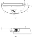
- a first joining partner 1 in the form of an aluminum stranded cable is welded to a second joining partner 2 in the form of a copper terminal.
- the welding process is preferably a metal ultrasonic welding process.
- the first joining partner 1 has a first contact 4 with a first measuring element 5 at a first cold junction 3 with a temperature of approximately 20°C (room temperature).
- the first measuring element 5 is designed in the form of a measuring line, whereby the material can be freely selected.
- the contact is made using a steel contact.
- the measuring line is connected at its first end to the first joining partner 1 and at its second end to a data processing system 7 at a measuring point 6.
- a hot spot 8 is created in the joining area of the first and second joining partners 1, 2, which has a temperature of approximately 250°C.
- a second contact 9 of the second measuring element 10 is arranged at a distance from the hot spot 8, wherein the second contact 9 also has a temperature of approximately 250°C in accordance with the hot spot 8.
- the second measuring element 10 is also designed in the form of a measuring line, wherein the second measuring element 10 has the same material as the second joining partner 2.
- the second measuring line 10 is connected at its first end to the second joining partner 2 and at its second end to a data processing system 7 at a second measuring point 11.
- the measuring line is made of copper. This allows for loss-free heat transfer between the copper terminal and the copper measuring line.
- the temperature difference between the first cold junction 3 of the first joining partner 1 and the hot junction 8 and the second contact 9 creates a potential difference P1 between the warmer and colder ends of the joining partners, causing a current to flow. This current flow is recorded and processed by the data processing system 7.
- a potential difference P2 can also be determined between the second contact 9 and the measuring point 11.
- the temperature of the second cold junction 12 is approximately 20°C, similar to the first cold junction 3.
- the potential difference P1 recorded by the data processing system 7 is then compared with material-specific calibration data stored in the data processing system 7 and further processed.
- the welding process can be controlled based on the potential difference P1 and the resulting data.
- Figure 2 shows a first joining partner 1 and a second joining partner 2 after the joining process.
- the first joining partner 1 is in the form of an aluminum stranded cable.
- the second joining element 2 is designed as a solid copper body. The connection was made using metal ultrasonic welding.
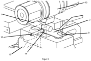
- a device for determining the temperature in a joining zone in a vibration welding process is described in Figure 3 shown.
- Welding is carried out by means of a sonotrode 13 arranged above the first and second joining partners 1, 2.
- contacting can be automated.
- Contacting 9 of the second joining partner 2 (copper terminal) is implemented in such a way that the second joining partner 2 is fixed during the joining process.
- the first joining partner 1 (aluminum stranded cable) is subject to severe plastic deformation and the associated change in geometry during the welding process, a spring-loaded measuring tip 14 made of aluminum is laterally inserted into the first joining partner 1 via a side slider 15 (hold-down device) of the welding system.
Landscapes
- Engineering & Computer Science (AREA)
- Mechanical Engineering (AREA)
- Physics & Mathematics (AREA)
- General Physics & Mathematics (AREA)
- Pressure Welding/Diffusion-Bonding (AREA)
Description
- Die Erfindung betrifft ein Verfahren zur Temperaturbestimmung in einer Fügezone bei einem Vibrationsschweißprozess und findet insbesondere für das Metall-Ultraschallschweißen von artfremden Werkstoffen Anwendung.
- Das Ultraschallschweißen ist eine Art von Pressschweißverfahren, bei dem die Fügepartner durch eine punktuell erhöhte Temperatur miteinander verbunden werden. Mittels einer Ultraschallschwingung wird Reibung erzeugt, welche in Kombination mit einem statischen Druck zur kontrollierten Temperaturerhöhung genutzt wird.
- In der Mikroelektronik und Verpackungstechnik wird dieses Verfahren seit Jahrzehnten angewendet. Ein weiterer wichtiger Anwendungsfall ist das Verbinden von Aluminiumlitzenkabeln zu Kupferableitern (Terminals) in der Herstellung von Elektrofahrzeugen. Zur Prozesskontrolle und Qualitätssicherung bietet es sich daher an, die Temperatur in der Fügezone zu überwachen und anhand dieser Gut- und Schlechtschweißungen ohne zerstörende Prüfverfahren zu identifizieren.
- Zur Bestimmung der Temperatur in der Fügezone beim Metall-Ultraschallschweißen werden häufig Thermoelemente (taktil) sowie Wärmebildkameras und Pyrometer (optisch) eingesetzt. Diese Verfahren sind von großen Messungenauigkeiten betroffen. Bei der optischen Temperaturmessung erfolgt der Blick von außen auf die Fügepartner, sodass nur oberflächliche Temperaturänderungen erfasst werden können. Dadurch sind kaum Rückschlüsse auf die inneren Vorgänge und die innere Temperatur der Fügezone möglich, da die Fügezone von den Schweißwerkzeugen und den Fügepartnern selbst verdeckt wird. Es sind somit nur qualitative Aussagen zur Temperatur möglich.
- Bei der taktilen Temperaturmessung hängt die gemessene Temperatur von der Platzierung der Thermoelemente ab.
- Thermoelemente funktionieren nach dem sogenannten Seebeck-Effekt, das heißt, tritt über die Länge eines elektrischen Leiters eine Temperaturdifferenz auf, so entsteht ein Potentialunterschied zwischen wärmerem und kälterem Ende des Leiters und es fließt ein Strom. Die Höhe des Potentialunterschieds ist für jeden Werkstoff spezifisch. Bringt man zwei verschiedene elektrische Leiterwerkstoffe in Kontakt und erwärmt diese an ihrer Kontaktstelle, lässt sich zwischen den kalten Enden der beiden Leiter aufgrund der elektromotorischen Kraft somit ein Potentialunterschied messen. Dieser korreliert direkt mit der Temperatur an der Heißstelle. Typischerweise wird dieser Effekt in Thermoelementen genutzt, welche häufig aus Paarungen aus NiCr/Ni, CuNi/Fe etc. bestehen.
- Da es beim Metall-Ultraschallschweißen zu lokal begrenzten Aufschmelzungen kommen kann, ist es kaum möglich, reproduzierbar und präzise die Fügezonentemperatur zu bestimmen. Die Einbringung von Thermoelementen muss zudem händisch durch den Bediener erfolgen. Das Thermoelement stellt in der Fügezone einen Fremdkörper dar, der den Schweißprozess negativ beeinflussen kann. Zudem wird das Thermoelement im Schweißprozess zerstört. Aufgrund dieser Tatsachen ist die Einbringung von Thermoelementen in die Fügezone für eine Prozessüberwachung unwirtschaftlich.
- Ein Verfahren nach dem Oberbegriff des Anspruchs 1 ist der
DE10 2013 107637 zu entnehmen. - Ein Verfahren zur Temperaturführung beim Widerstandsschweißen wird in der Druckschrift
DD 2 52 778 A1 - In der Druckschrift
JP 2006-159 277 A - Aus der Druckschrift
DE 22 10 855 C2 sind ein Verfahren und eine Vorrichtung zum direkten Verbinden von Metallteilen miteinander und Anwendung des Verfahrens beschrieben. Das Verbinden der Metallteile erfolgt durch Energieimpulse, die durch Vibration erzeugt werden und im Schall- bzw. Ultraschallbereich liegen. Mit dem Verfahren können unter anderem Kupferbauteile mit Aluminiumbauteilen verbunden werden. Während des Verbindungsprozesses können Temperaturen auftreten, die über 1000 °C liegen, wobei diese jedoch eng lokal begrenzt sind. Somit wird eine großflächige Aufheizung der Bauteile vermieden. Die Temperatur wird mittels eines Thermoelements erfasst. - Die Energie in der Fügestelle, die als thermoelektrisches Potential gemessen wird, kann an der Grenzfläche zweier miteinander zu verbindender Schichten angezeigt werden.
- In der Druckschrift
DE 42 06 584 C2 wird eine Vorrichtung und ein Verfahren zum Verbinden zweier Bauteile mittels Ultraschalls beschrieben. Gemäß dem Verfahren wird eine Temperaturmessung in unmittelbarer Nähe der Schweißstelle durchgeführt, um die optimalen Schweißparameter zu ermitteln. Mit Hilfe der Temperaturmessung als Führungsgröße wird so ein Regelkreis aufgebaut. Zur Temperaturmessung können sowohl berührungslose als auch berührende Systeme zur Anwendung kommen, wobei aus Kostengründen und wegen der größeren Messgenauigkeit den berührenden Ausführungen der Vorzug eingeräumt wird. In diesem Zusammenhang sollen Thermoelemente, die in der Sonotrodenspitze angeordnet sind, zum Einsatz kommen. Es besteht jedoch auch die Möglichkeit, dass das Thermoelement auf der Schweißnaht geführt wird. - Die Druckschrift
DE 10 2010 050 387 A1 beschreibt ein Verfahren und ein System zur Online-Qualitätsüberwachung und -Steuerung eines Vibrationsschweißprozesses. Gemäß dem Verfahren werden Daten der Fügestelle mithilfe von Sensoren erfasst, die in Bezug auf Schweißgrenzflächen eines Werkstückes positioniert sind. Die Messwerte werden zuerst ermittelt und folgend mit, in einer Datenbank abgelegten Messwerte verglichen. Das Ergebnis dieses Vergleichs wird dazu verwendet, die Schweißprozessparameter zu optimieren. - Dabei liefern die Messwerte keine konkreten physikalischen Größen (Temperatur, Kraft, elektrischer Strom usw.), sondern es werden Merkmale klassifiziert. Die Summe dieser Merkmale lässt Schlüsse zu, die die Qualität der erzeugten Schweißnaht charakterisieren. Die Messwerterfassung und der Vergleich mit Datensätzen der Datenbank erfolgt online, also während des Schweißvorgangs. Somit ist es möglich, eine Prozessoptimierung während des Fügens vorzunehmen.
- Aufgabe der Erfindung ist es, ein Verfahren zur Temperaturbestimmung in einer Fügezone zu entwickeln, welche eine zerstörungsfreie Prozesskontrolle und Qualitätssicherung in Bezug auf die Temperatur der Schweißstelle für Pressschweißverfahren bereitstellen.
- Diese Aufgabe wird mit den Merkmalen des ersten Patentanspruchs gelöst.
- Vorteilhafte Ausgestaltungen ergeben sich aus den Unteransprüchen.
- Das Verfahren dient der Temperaturbestimmung in einer Fügezone in einem Vibrationsschweißprozess, wobei ein erster Fügepartner und ein zweiter Fügepartner miteinander verschweißt werden, wobei der erste und zweite Fügepartner als Thermoelement agieren und mittels eines, mit dem ersten Fügepartner an einer Kaltstelle kontaktierten ersten Messelements und eines, mit dem zweiten Fügepartner zu einer Heißstelle beabstandet kontaktierten zweiten Messelements eine Potentialdifferenz zwischen dem ersten und zweiten Fügepartner während des Schweißprozesses erfasst wird, wobei das zweite Messelement im Bereich einer Kontaktierung mit dem zweiten Fügepartner eine Temperatur höher der Temperatur der Kaltstelle und einen artgleichen Werkstoff zu dem zweiten Fügepartner aufweist, wobei die Potentialdifferenz mit materialspezifischen Kalibrierungsdaten abgeglichen und mittels eines Datenverarbeitungssystems verarbeitet wird und dass der Schweißprozess anhand der ermittelten Potentialdifferenz gesteuert wird, der erste Fügepartner in Form eines Litzenkabels ausgebildet ist, das erste Messelement als Messleitung ausgebildet ist, die mit ihrem ersten Ende mit dem ersten Fügepartner und mit ihrem zweiten Ende an einem Messpunkt mit einem Datenverarbeitungssystem verbunden ist, der erste Fügepartner und/oder das erste Messelement aus Aluminium hergestellt sind, der zweite Fügepartner und/oder das zweite Messelement aus Kupfer hergestellt sind und die Temperatur der Kaltstelle der Zimmertemperatur von ca. 20° entspricht und dass die Kontaktierung im Bereich der Heißstelle bei einer Temperatur höher der Zimmertemperatur erfolgt. Bevorzugt wird die Potentialdifferenz mit materialspezifischen Kalibrierungsdaten abgeglichen so dass die ermittelten Daten mittels eines Datenverarbeitungssystems verarbeitet werden.
- Besonders bevorzugt kann der Schweißprozess anhand der ermittelten Potentialdifferenz gesteuert werden, wobei der Vibrationsschweißprozess in einer vorteilhaften Ausgestaltung ein Metall-Ultraschallschweißen ist.
- Vorteilhafter Weise ist der zweite Fügepartner in Form eines Litzenkabels oder in Form eines massiven Körpers ausgebildet. Daher können auch beide Fügepartner in Form von massiven Körpern oder in Form von Litzenkabeln ausgebildet sein. Des Weiteren kann auch für davon abweichende Fügepartnergeometrien, wie beispielsweise Blech/Blech oder Folie/Folie das Verfahren Anwendung finden. Eine Kontaktierung kann hier aufgrund der wesentlich geringeren Deformation der Fügepartner auch um einiges einfacher ausfallen.
- Bevorzugt entspricht die Temperatur der Kaltstelle im Wesentlichen der Zimmertemperatur. Die zweite Kontaktierung ist im Bereich der Heißstelle angeordnet, wobei im Bereich der zweiten Kontaktierung eine Temperatur höher der Zimmertemperatur anliegt. Der erste Fügepartner und das erste Messelement sind erfindungsgemäß aus Aluminium. Der zweite Fügepartner und das zweite Messelement sind erfindungsgemäß aus Kupfer hergestellt. Jedoch sind auch andere artfremde Werkstoffpaarungen geeignet, beispielsweise Aluminium/Nickel, Nickel/Kupfer, oder ähnliches.
- Die Vorrichtung zur Temperaturbestimmung in einer Fügezone in einem Vibrationsschweißprozess, wobei ein erster Fügepartner und ein zweiter Fügepartner miteinander schweißbar sind, weist eine erste Kontaktierung des ersten Fügepartners mit einem ersten Messelement an einer ersten Kaltstelle und eine zweite Kontaktierung des zweiten Fügepartners mit einem zweiten Messelement zu einer Heißstelle beabstandet auf, wobei die Fügepartner über die Messelemente mit einer Datenverarbeitung verbunden sind. Das zweite Messelement weist des Weiteren einen artgleichen Werkstoff zu dem zweiten Fügepartner auf.
- Bevorzugt ist die Vorrichtung so ausgebildet, dass zwischen dem zweiten Messelement und der Datenverarbeitung eine zweite Kaltstelle angeordnet ist.
- In einer ersten Ausgestaltung ist das erste Messelement in Form einer Messleitung ausgebildet. Alternativ kann das erste Messelement in Form einer federnden Messspitze ausgebildet sein. Die federnde Messspitze kann mittels eines Seitenschiebers der Schweißanlage zugeführt sein.
- Die Erfindung wird nachfolgend an einem Ausführungsbeispiel und zugehörigen Zeichnungen näher erläutert.
- Es zeigen:
- Figur 1
- eine schematische Darstellung des erfindungsgemäßen Verfahrens,
- Figur 2
- einen Metall-Ultraschallgeschweißten Verbund aus einem Aluminiumkabel und einem Kupferterminal,
- Figur 3
- eine Vorrichtung zum Messen einer Potentialdifferenz.
- Das Verfahren wird in einer schematischen Darstellung in
Figur 1 dargestellt. Gemäß den Ausführungsbeispielen wird ein erster Fügepartner 1 in Form eines Aluminiumlitzenkabels mit einem zweiten Fügepartner 2 in Form eines Kupferterminals verschweißt. Das Schweißverfahren ist bevorzugt ein Metall-Ultraschallschweißverfahren. - Der erste Fügepartner 1 weist an einer ersten Kaltstelle 3 mit einer Temperatur von ca. 20°C (Zimmertemperatur) eine erste Kontaktierung 4 mit einem ersten Messelement 5 auf. Das erste Messelement 5 ist in Form einer Messleitung ausgebildet, wobei das Material beliebig gewählt sein kann. Die Kontaktierung erfolgt in diesem Ausführungsbeispiel mittels einer Stahlkontaktierung. Die Messleitung ist mit ihrem ersten Ende mit dem ersten Fügepartner 1 und mit ihrem zweiten Ende an einem Messpunkt 6 mit einem Datenverarbeitungssystem 7 verbunden.
- Im Fügebereich des ersten und zweiten Fügepartners 1, 2 entsteht während des Schweißvorgangs eine Heißstelle 8, die eine Temperatur von ca. 250°C aufweist.
- Zu der Heißstelle 8 beabstandet ist eine zweite Kontaktierung 9 des zweiten Messelements 10 angeordnet, wobei die zweite Kontaktierung 9 ebenfalls gemäß der Heißstelle 8 eine Temperatur von ca. 250°C aufweist. Das zweite Messelement 10 ist ebenfalls in Form einer Messleitung ausgebildet, wobei das zweite Messelement 10 den gleichen Werkstoff wie der zweite Fügepartner 2 aufweist. Die zweite Messleitung 10 ist mit ihrem ersten Ende mit dem zweiten Fügepartner 2 und mit ihrem zweiten Ende an einem zweiten Messpunkt 11 mit einem Datenverarbeitungssystem 7 verbunden. In der Ausgestaltung ist die Messleitung aus Kupfer gebildet. So kann ein verlustfreier Wärmeübergang zwischen dem Kupfer-Terminal und der Kupfer-Messleitung erreicht werden.
- Durch die Temperaturdifferenz zwischen der ersten Kaltstelle 3 des ersten Fügepartners 1 und der Heißstelle 8 sowie der zweiten Kontaktierung 9 entsteht ein Potentialunterschied P1 zwischen dem wärmeren und dem kälteren Ende der Fügepartner, wodurch ein Strom fließt. Dieser Stromfluss wird mittels des Datenverarbeitungssystems 7 erfasst und verarbeitet.
- Da sich an dem zweiten Messpunkt 11 aufgrund des Materialunterschieds zwischen der Kupferleitung und dem Messgerät eine zweite Kaltstelle 12 bildet, kann zwischen der zweiten Kontaktierung 9 und dem Messpunkt 11 ebenfalls ein Potentialunterschied P2 ermittelt werden. Die Temperatur der zweiten Kaltstelle 12 beträgt ähnlich der ersten Kaltstelle 3 ca. 20°C.
- Im Folgenden wird die, von dem Datenverarbeitungssystem 7 erfasste Potentialdifferenz P1 mit materialspezifischen Kalibrierungsdaten, welche in dem Datenverarbeitungssystem 7 hinterlegt sind, abgeglichen und weiterverarbeitet. Anhand der Potentialdifferenz P1 und den daraus resultierenden Daten kann der Schweißprozess gesteuert werden.
-
Figur 2 zeigt einen ersten Fügepartner 1 und einen zweiten Fügepartner 2 nach dem Fügeprozess. Der erste Fügepartner 1 ist in Form eines Aluminiumlitzenkalbels ausgebildet. Das zweite Fügeelement 2 ist in Form eines massiven Körpers aus Kupfer ausgestaltet. Die Verbindung erfolgte mittels Metall-Ultraschallschweißens. - Eine Vorrichtung zur Temperaturbestimmung in einer Fügezone in einem Vibrationsschweißprozess ist in
Figur 3 dargestellt. Das Schweißen erfolgt mittels einer über dem ersten und zweiten Fügepartner 1, 2 angeordneten Sonotrode 13. Für eine industrielle Produktion kann die Kontaktierung automatisiert erfolgen. Die Kontaktierung 9 des zweiten Fügepartners 2 (Kupfer-Terminal) wird derart umgesetzt, dass der zweite Fügepartner 2 während des Fügeprozesses fixiert ist. Da der erste Fügepartner 1 (Aluminiumlitzenkabel) im Schweißprozess einer starken plastischen Deformation und damit einhergehend einer Geometrieänderung unterworfen ist erfolgt daher eine laterale Einbringung einer federnden Messspitze 14 aus Aluminium in den ersten Fügepartner 1 über einen Seitenschieber 15 (Niederhalter) der Schweißanlage. Alternativ wäre eine federnd gelagerte Kontaktierung auf die Kopfseite des Litzenkabels oder die Anbringung eines Messkabels am entfernten und kalten Ende (Kaltstelle) des Litzenkabels denkbar. Die Messspitze 14 ist aus Reinaluminium ausgebildet und weist ein isolierendes Keramikröhrchen 16 um die Messspitze 14 auf. -
- 1
- Erster Fügepartner
- 2
- Zweiter Fügepartner
- 3
- Erste Kaltstelle
- 4
- Erste Kontaktierung
- 5
- Erstes Messelement
- 6
- Erster Messpunkt
- 7
- Datenverarbeitungssystem
- 8
- Heißstelle
- 9
- Zweite Kontaktierung
- 10
- Zweites Messelement
- 11
- Zweiter Messpunkt
- 12
- Zweite Kaltstelle
- 13
- Messspitze
- 14
- Seitenschieber
Claims (3)
- Verfahren zur Temperaturbestimmung in einer Fügezone in einem Vibrationsschweißprozess, wobei ein erster Fügepartner (1) und ein zweiter Fügepartner (2) miteinander verschweißt werden, wobei der erste Fügepartner in Form eines Litzenkabels ausgebildet ist, der erste Fügepartner aus Aluminium hergestellt ist, und der zweite Fügepartner aus Kupfer hergestellt ist, dadurch gekennzeichnet, dass der erste und zweite Fügepartner (1, 2) als Thermoelement agieren wobei mittels eines, mit dem ersten Fügepartner (1) an einer Kaltstelle (3) kontaktierten ersten Messelements (5) und eines, mit dem zweiten Fügepartner (2) zu einer Heißstelle (8) beabstandet kontaktierten zweiten Messelements (10) eine Potentialdifferenz (P1) zwischen dem ersten und zweiten Fügepartner (1, 2) während des Schweißprozesses erfasst wird,- wobei das zweite Messelement (10) im Bereich einer Kontaktierung (9) mit dem zweiten Fügepartner (2) eine Temperatur höher der Temperatur der Kaltstelle (3) und aus Kupfer besteht,- dass die Potentialdifferenz (P1) mit materialspezifischen Kalibrierungsdaten abgeglichen und mittels eines Datenverarbeitungssystems (7) verarbeitet wird und dass der Schweißprozess anhand der ermittelten Potentialdifferenz (P1) gesteuert wird- dass das erste Messelement (5) als Messleitung ausgebildet ist, die mit ihrem ersten Ende mit dem ersten Fügepartner (1) und mit ihrem zweiten Ende an einem Messpunkt (6) mit dem Datenverarbeitungssystem (7) verbunden ist,- dass das zweite Messelement (1) als Messleitung ausgebildet ist, die mit ihrem ersten Ende mit dem zweiten Fügepartner (2) und mit ihrem zweiten Ende an einem zweiten Messpunkt (11) mit dem Datenverarbeitungssystem (7) verbunden ist,- dass das erste Messelement (5) aus Aluminium hergestellt ist,- dass die Temperatur der Kaltstelle der Zimmertemperatur von ca. 20° entspricht und dass die Kontaktierung im Bereich der Heißstelle (8) bei einer Temperatur höher der Zimmertemperatur erfolgt.
- Verfahren nach einem Anspruch 1, dadurch gekennzeichnet, dass der Vibrationsschweißprozess ein Metall-Ultraschallschweißen ist.
- Verfahren nach Anspruch 1 oder 2, dadurch gekennzeichnet, dass der zweite Fügepartner (2) in Form eines Litzenkabels oder eines massiven Körpers ausgebildet ist.
Applications Claiming Priority (2)
| Application Number | Priority Date | Filing Date | Title |
|---|---|---|---|
| DE102021117697.2A DE102021117697B3 (de) | 2021-07-08 | 2021-07-08 | Verfahren zur Temperaturbestimmung in einer Fügezone |
| PCT/DE2022/100436 WO2023280340A1 (de) | 2021-07-08 | 2022-06-10 | Verfahren zur temperaturbestimmung in einer fügezone |
Publications (3)
| Publication Number | Publication Date |
|---|---|
| EP4366905A1 EP4366905A1 (de) | 2024-05-15 |
| EP4366905B1 true EP4366905B1 (de) | 2025-06-04 |
| EP4366905C0 EP4366905C0 (de) | 2025-06-04 |
Family
ID=81256446
Family Applications (1)
| Application Number | Title | Priority Date | Filing Date |
|---|---|---|---|
| EP22740282.3A Active EP4366905B1 (de) | 2021-07-08 | 2022-06-10 | Verfahren zur temperaturbestimmung in einer fügezone |
Country Status (4)
| Country | Link |
|---|---|
| US (1) | US12625013B2 (de) |
| EP (1) | EP4366905B1 (de) |
| DE (1) | DE102021117697B3 (de) |
| WO (1) | WO2023280340A1 (de) |
Families Citing this family (1)
| Publication number | Priority date | Publication date | Assignee | Title |
|---|---|---|---|---|
| EP4717392A1 (de) | 2024-09-27 | 2026-04-01 | Telsonic Holding AG | Verfahren zur zerstörungsfreien prüfung einer verbindung zwischen zwei bauteilen, verfahren zum erzeugen einer schweissverbindung zwischen wenigstens zwei bauteilen, schweissvorrichtung, computerprogrammprodukt, computerlesbares speichermedium, verfahren zum trainieren eines maschinellen lernmodells zum vorhersagen einer schweissqualität sowie maschinenlernmodell zum vorhersagen einer schweissqualität |
Family Cites Families (12)
| Publication number | Priority date | Publication date | Assignee | Title |
|---|---|---|---|---|
| GB1385473A (en) | 1966-09-01 | 1975-02-26 | Luc Penelope Jane Vesey | Bonding |
| US4529115A (en) * | 1983-04-12 | 1985-07-16 | Fairchild Industries, Inc. | Thermally assisted ultrasonic welding apparatus and process |
| DD252778A1 (de) | 1986-09-24 | 1987-12-30 | Zentralinstitut Schweiss | Verfahren zur temperaturfuehrung beim widerstandsschweiss- und loetprozess |
| DE4206584C2 (de) | 1992-03-03 | 1994-03-10 | Fraunhofer Ges Forschung | Vorrichtung und Verfahren zum Verbinden zweier Bauteile mittels Ultraschall |
| JP4541121B2 (ja) | 2004-12-10 | 2010-09-08 | 矢崎総業株式会社 | 超音波溶接方法及び超音波溶接装置 |
| DE102010050387B4 (de) | 2009-11-09 | 2023-05-04 | GM Global Technology Operations LLC (n. d. Ges. d. Staates Delaware) | Vibrationsschweißsystem und Verfahren zum Überwachen und Steuern eines Vibrationsschweißsystems während eines Vibrationsschweißprozesses |
| US8702882B2 (en) * | 2009-11-09 | 2014-04-22 | GM Global Technology Operations LLC | Method and system for online quality monitoring and control of a vibration welding process |
| DE102013214042A1 (de) | 2013-07-17 | 2015-01-22 | Voith Patent Gmbh | Transportband mit Verschlussnaht |
| DE102013107637A1 (de) | 2013-07-18 | 2015-01-22 | Schunk Sonosystems Gmbh | Verfahren zur Herstellung eines Knotens durch Schweißen |
| DE102015218961A1 (de) | 2015-02-10 | 2016-08-11 | Conti Temic Microelectronic Gmbh | Gehäuse und Verfahren zu dessen Herstellung |
| US10105787B2 (en) | 2015-06-05 | 2018-10-23 | GM Global Technology Operations LLC | Systems and methods for ultrasonic welding |
| JP2020161529A (ja) | 2019-03-25 | 2020-10-01 | 三菱電機株式会社 | 超音波接合装置、超音波接合構造、超音波接合方法および半導体装置の製造方法 |
-
2021
- 2021-07-08 DE DE102021117697.2A patent/DE102021117697B3/de active Active
-
2022
- 2022-06-10 EP EP22740282.3A patent/EP4366905B1/de active Active
- 2022-06-10 US US18/290,292 patent/US12625013B2/en active Active
- 2022-06-10 WO PCT/DE2022/100436 patent/WO2023280340A1/de not_active Ceased
Also Published As
| Publication number | Publication date |
|---|---|
| WO2023280340A1 (de) | 2023-01-12 |
| DE102021117697B3 (de) | 2022-05-12 |
| US12625013B2 (en) | 2026-05-12 |
| EP4366905A1 (de) | 2024-05-15 |
| EP4366905C0 (de) | 2025-06-04 |
| US20240230423A1 (en) | 2024-07-11 |
Similar Documents
| Publication | Publication Date | Title |
|---|---|---|
| EP3215310B1 (de) | Verfahren zum bearbeiten eines ersten bauelements und eines zweiten bauelemetens durch laserschweissen sowie entsprechende vorrichtung | |
| EP2655004B1 (de) | HOCHFREQUENZSCHWEIßEN VON SANDWICHBLECHEN | |
| DE112013001015T5 (de) | Verfahren und Vorrichtung zum elektrischen Verbinden mit Wärme | |
| DE102014208706A1 (de) | Verfahren und Vorrichtung zum Fügen eines Verbundblechbauteils mit einem Funktionselement | |
| DE102021117697B3 (de) | Verfahren zur Temperaturbestimmung in einer Fügezone | |
| EP2790865B1 (de) | Verfahren zum fügen zweier im wesentlichen blechartiger werkstücke mittels reibquetschschweissen | |
| DE102008046692A1 (de) | Verfahren und Einrichtung zur zerstörungsfreien Prüfung von Rührreibschweißnähten | |
| DE102015112199A1 (de) | Lötverfahren | |
| EP2895830A2 (de) | Verfahren zum verpressen oder verschweissen der schutzkappe eines hochtemperatursensors | |
| Kerstens et al. | Heat distribution in resistance upset butt welding | |
| WO2023020888A1 (de) | Schweisseinrichtung und schweissverfahren | |
| DE102019108813A1 (de) | Verfahren zum mechanischen Fügen | |
| DE102015207517A1 (de) | Fügesystem | |
| EP2376402B1 (de) | Verfahren zur herstellung von metall-keramik-verbindungen | |
| Baskoro et al. | Effects of welding time and welding current to weld nugget and shear load on electrical resistance spot welding of cold rolled sheet for body construction | |
| US7355142B2 (en) | Resistance welding electrode, welded copper flex lead, and method for making same | |
| US3811028A (en) | Thermostat metal and method of making | |
| DE102019130641A9 (de) | "Verfahren zum Verbinden von einem Sandwichblech" | |
| EP2895832A2 (de) | Hochtemperatursensor und verfahren zur herstellung einer schutzkappe für einen hochtemperatursensor | |
| Zhao et al. | Long-term Performance Analysis of Welded Joints Using Ultrasonic Wire Harness in Addition with Ni (Cu), Ag (Cu) and Sn (Cu) Clads | |
| DE102018120241B4 (de) | Verfahren zum Bestimmen der Qualität einer Schweiß- oder Lötverbindung bei der Fertigung von Sägeblättern | |
| DE4328337C1 (de) | Verfahren zur Bestimmung der Temperatur an einer Punktschweißverbindung sowie Anwendung des Verfahrens zur Beurteilung der Qualität der Punktschweißverbindung | |
| EP3337635B1 (de) | Vorrichtung und verfahren zur niederohmigen verschweissung von blechen mit hoher taktzahl | |
| EP0728054A1 (de) | Verfahren zur überwachung einer schweissmaschine, anwendung des verfahrens zur regelung der schweissmaschine sowie vorrichtung zur durchführung des verfahrens | |
| DE4039847C2 (de) |
Legal Events
| Date | Code | Title | Description |
|---|---|---|---|
| STAA | Information on the status of an ep patent application or granted ep patent |
Free format text: STATUS: UNKNOWN |
|
| STAA | Information on the status of an ep patent application or granted ep patent |
Free format text: STATUS: THE INTERNATIONAL PUBLICATION HAS BEEN MADE |
|
| PUAI | Public reference made under article 153(3) epc to a published international application that has entered the european phase |
Free format text: ORIGINAL CODE: 0009012 |
|
| STAA | Information on the status of an ep patent application or granted ep patent |
Free format text: STATUS: REQUEST FOR EXAMINATION WAS MADE |
|
| 17P | Request for examination filed |
Effective date: 20231107 |
|
| AK | Designated contracting states |
Kind code of ref document: A1 Designated state(s): AL AT BE BG CH CY CZ DE DK EE ES FI FR GB GR HR HU IE IS IT LI LT LU LV MC MK MT NL NO PL PT RO RS SE SI SK SM TR |
|
| DAV | Request for validation of the european patent (deleted) | ||
| DAX | Request for extension of the european patent (deleted) | ||
| GRAP | Despatch of communication of intention to grant a patent |
Free format text: ORIGINAL CODE: EPIDOSNIGR1 |
|
| STAA | Information on the status of an ep patent application or granted ep patent |
Free format text: STATUS: GRANT OF PATENT IS INTENDED |
|
| GRAS | Grant fee paid |
Free format text: ORIGINAL CODE: EPIDOSNIGR3 |
|
| INTG | Intention to grant announced |
Effective date: 20250226 |
|
| GRAA | (expected) grant |
Free format text: ORIGINAL CODE: 0009210 |
|
| STAA | Information on the status of an ep patent application or granted ep patent |
Free format text: STATUS: THE PATENT HAS BEEN GRANTED |
|
| AK | Designated contracting states |
Kind code of ref document: B1 Designated state(s): AL AT BE BG CH CY CZ DE DK EE ES FI FR GB GR HR HU IE IS IT LI LT LU LV MC MK MT NL NO PL PT RO RS SE SI SK SM TR |
|
| REG | Reference to a national code |
Ref country code: GB Ref legal event code: FG4D Free format text: NOT ENGLISH |
|
| REG | Reference to a national code |
Ref country code: CH Ref legal event code: EP |
|
| REG | Reference to a national code |
Ref country code: IE Ref legal event code: FG4D Free format text: LANGUAGE OF EP DOCUMENT: GERMAN |
|
| U01 | Request for unitary effect filed |
Effective date: 20250606 |
|
| U07 | Unitary effect registered |
Designated state(s): AT BE BG DE DK EE FI FR IT LT LU LV MT NL PT RO SE SI Effective date: 20250616 |
|
| PGFP | Annual fee paid to national office [announced via postgrant information from national office to epo] |
Ref country code: AT Payment date: 20250721 Year of fee payment: 4 |
|
| U20 | Renewal fee for the european patent with unitary effect paid |
Year of fee payment: 4 Effective date: 20250620 |
|
| PG25 | Lapsed in a contracting state [announced via postgrant information from national office to epo] |
Ref country code: ES Free format text: LAPSE BECAUSE OF FAILURE TO SUBMIT A TRANSLATION OF THE DESCRIPTION OR TO PAY THE FEE WITHIN THE PRESCRIBED TIME-LIMIT Effective date: 20250604 |
|
| PG25 | Lapsed in a contracting state [announced via postgrant information from national office to epo] |
Ref country code: NO Free format text: LAPSE BECAUSE OF FAILURE TO SUBMIT A TRANSLATION OF THE DESCRIPTION OR TO PAY THE FEE WITHIN THE PRESCRIBED TIME-LIMIT Effective date: 20250904 Ref country code: GR Free format text: LAPSE BECAUSE OF FAILURE TO SUBMIT A TRANSLATION OF THE DESCRIPTION OR TO PAY THE FEE WITHIN THE PRESCRIBED TIME-LIMIT Effective date: 20250905 |
|
| PG25 | Lapsed in a contracting state [announced via postgrant information from national office to epo] |
Ref country code: PL Free format text: LAPSE BECAUSE OF FAILURE TO SUBMIT A TRANSLATION OF THE DESCRIPTION OR TO PAY THE FEE WITHIN THE PRESCRIBED TIME-LIMIT Effective date: 20250604 |
|
| U79 | Statement concerning licences of right filed [unitary effect] |
Effective date: 20250908 |
|
| PG25 | Lapsed in a contracting state [announced via postgrant information from national office to epo] |
Ref country code: HR Free format text: LAPSE BECAUSE OF FAILURE TO SUBMIT A TRANSLATION OF THE DESCRIPTION OR TO PAY THE FEE WITHIN THE PRESCRIBED TIME-LIMIT Effective date: 20250604 |
|
| PGFP | Annual fee paid to national office [announced via postgrant information from national office to epo] |
Ref country code: CH Payment date: 20250828 Year of fee payment: 4 |
|
| PG25 | Lapsed in a contracting state [announced via postgrant information from national office to epo] |
Ref country code: RS Free format text: LAPSE BECAUSE OF FAILURE TO SUBMIT A TRANSLATION OF THE DESCRIPTION OR TO PAY THE FEE WITHIN THE PRESCRIBED TIME-LIMIT Effective date: 20250904 |
|
| PG25 | Lapsed in a contracting state [announced via postgrant information from national office to epo] |
Ref country code: IS Free format text: LAPSE BECAUSE OF FAILURE TO SUBMIT A TRANSLATION OF THE DESCRIPTION OR TO PAY THE FEE WITHIN THE PRESCRIBED TIME-LIMIT Effective date: 20251004 |
|
| PG25 | Lapsed in a contracting state [announced via postgrant information from national office to epo] |
Ref country code: SM Free format text: LAPSE BECAUSE OF FAILURE TO SUBMIT A TRANSLATION OF THE DESCRIPTION OR TO PAY THE FEE WITHIN THE PRESCRIBED TIME-LIMIT Effective date: 20250604 |
|
| PG25 | Lapsed in a contracting state [announced via postgrant information from national office to epo] |
Ref country code: CZ Free format text: LAPSE BECAUSE OF FAILURE TO SUBMIT A TRANSLATION OF THE DESCRIPTION OR TO PAY THE FEE WITHIN THE PRESCRIBED TIME-LIMIT Effective date: 20250604 |
|
| PG25 | Lapsed in a contracting state [announced via postgrant information from national office to epo] |
Ref country code: SK Free format text: LAPSE BECAUSE OF FAILURE TO SUBMIT A TRANSLATION OF THE DESCRIPTION OR TO PAY THE FEE WITHIN THE PRESCRIBED TIME-LIMIT Effective date: 20250604 |
|
| PG25 | Lapsed in a contracting state [announced via postgrant information from national office to epo] |
Ref country code: MC Free format text: LAPSE BECAUSE OF FAILURE TO SUBMIT A TRANSLATION OF THE DESCRIPTION OR TO PAY THE FEE WITHIN THE PRESCRIBED TIME-LIMIT Effective date: 20250604 |
|
| PLBE | No opposition filed within time limit |
Free format text: ORIGINAL CODE: 0009261 |
|
| STAA | Information on the status of an ep patent application or granted ep patent |
Free format text: STATUS: NO OPPOSITION FILED WITHIN TIME LIMIT |
|
| PG25 | Lapsed in a contracting state [announced via postgrant information from national office to epo] |
Ref country code: IE Free format text: LAPSE BECAUSE OF NON-PAYMENT OF DUE FEES Effective date: 20250610 |
|
| REG | Reference to a national code |
Ref country code: CH Ref legal event code: L10 Free format text: ST27 STATUS EVENT CODE: U-0-0-L10-L00 (AS PROVIDED BY THE NATIONAL OFFICE) Effective date: 20260416 |
|
| 26N | No opposition filed |
Effective date: 20260305 |
|
| U20 | Renewal fee for the european patent with unitary effect paid |
Year of fee payment: 5 Effective date: 20260408 |