EP4366221A1 - Verfahren und vorrichtung für wiederholungsschema für downlink-datenkanal in kommunikationssystemen - Google Patents
Verfahren und vorrichtung für wiederholungsschema für downlink-datenkanal in kommunikationssystemen Download PDFInfo
- Publication number
- EP4366221A1 EP4366221A1 EP23207735.4A EP23207735A EP4366221A1 EP 4366221 A1 EP4366221 A1 EP 4366221A1 EP 23207735 A EP23207735 A EP 23207735A EP 4366221 A1 EP4366221 A1 EP 4366221A1
- Authority
- EP
- European Patent Office
- Prior art keywords
- pdsch
- lte
- information
- dci
- resource
- Prior art date
- Legal status (The legal status is an assumption and is not a legal conclusion. Google has not performed a legal analysis and makes no representation as to the accuracy of the status listed.)
- Pending
Links
Images


Classifications
-
- H—ELECTRICITY
- H04—ELECTRIC COMMUNICATION TECHNIQUE
- H04L—TRANSMISSION OF DIGITAL INFORMATION, e.g. TELEGRAPHIC COMMUNICATION
- H04L5/00—Arrangements affording multiple use of the transmission path
- H04L5/003—Arrangements for allocating sub-channels of the transmission path
- H04L5/0044—Allocation of payload; Allocation of data channels, e.g. PDSCH or PUSCH
-
- H—ELECTRICITY
- H04—ELECTRIC COMMUNICATION TECHNIQUE
- H04W—WIRELESS COMMUNICATION NETWORKS
- H04W72/00—Local resource management
- H04W72/04—Wireless resource allocation
- H04W72/044—Wireless resource allocation based on the type of the allocated resource
- H04W72/0446—Resources in time domain, e.g. slots or frames
-
- H—ELECTRICITY
- H04—ELECTRIC COMMUNICATION TECHNIQUE
- H04L—TRANSMISSION OF DIGITAL INFORMATION, e.g. TELEGRAPHIC COMMUNICATION
- H04L5/00—Arrangements affording multiple use of the transmission path
- H04L5/003—Arrangements for allocating sub-channels of the transmission path
- H04L5/0053—Allocation of signalling, i.e. of overhead other than pilot signals
-
- H—ELECTRICITY
- H04—ELECTRIC COMMUNICATION TECHNIQUE
- H04L—TRANSMISSION OF DIGITAL INFORMATION, e.g. TELEGRAPHIC COMMUNICATION
- H04L1/00—Arrangements for detecting or preventing errors in the information received
- H04L1/08—Arrangements for detecting or preventing errors in the information received by repeating transmission, e.g. Verdan system
-
- H—ELECTRICITY
- H04—ELECTRIC COMMUNICATION TECHNIQUE
- H04L—TRANSMISSION OF DIGITAL INFORMATION, e.g. TELEGRAPHIC COMMUNICATION
- H04L1/00—Arrangements for detecting or preventing errors in the information received
- H04L1/12—Arrangements for detecting or preventing errors in the information received by using return channel
- H04L1/16—Arrangements for detecting or preventing errors in the information received by using return channel in which the return channel carries supervisory signals, e.g. repetition request signals
- H04L1/18—Automatic repetition systems, e.g. Van Duuren systems
- H04L1/1867—Arrangements specially adapted for the transmitter end
- H04L1/189—Transmission or retransmission of more than one copy of a message
-
- H—ELECTRICITY
- H04—ELECTRIC COMMUNICATION TECHNIQUE
- H04L—TRANSMISSION OF DIGITAL INFORMATION, e.g. TELEGRAPHIC COMMUNICATION
- H04L1/00—Arrangements for detecting or preventing errors in the information received
- H04L1/12—Arrangements for detecting or preventing errors in the information received by using return channel
- H04L1/16—Arrangements for detecting or preventing errors in the information received by using return channel in which the return channel carries supervisory signals, e.g. repetition request signals
- H04L1/18—Automatic repetition systems, e.g. Van Duuren systems
- H04L1/1867—Arrangements specially adapted for the transmitter end
- H04L1/1896—ARQ related signaling
-
- H—ELECTRICITY
- H04—ELECTRIC COMMUNICATION TECHNIQUE
- H04L—TRANSMISSION OF DIGITAL INFORMATION, e.g. TELEGRAPHIC COMMUNICATION
- H04L5/00—Arrangements affording multiple use of the transmission path
- H04L5/0091—Signalling for the administration of the divided path, e.g. signalling of configuration information
- H04L5/0094—Indication of how sub-channels of the path are allocated
-
- H—ELECTRICITY
- H04—ELECTRIC COMMUNICATION TECHNIQUE
- H04W—WIRELESS COMMUNICATION NETWORKS
- H04W72/00—Local resource management
- H04W72/12—Wireless traffic scheduling
- H04W72/1263—Mapping of traffic onto schedule, e.g. scheduled allocation or multiplexing of flows
- H04W72/1268—Mapping of traffic onto schedule, e.g. scheduled allocation or multiplexing of flows of uplink data flows
-
- H—ELECTRICITY
- H04—ELECTRIC COMMUNICATION TECHNIQUE
- H04W—WIRELESS COMMUNICATION NETWORKS
- H04W72/00—Local resource management
- H04W72/12—Wireless traffic scheduling
- H04W72/1263—Mapping of traffic onto schedule, e.g. scheduled allocation or multiplexing of flows
- H04W72/1273—Mapping of traffic onto schedule, e.g. scheduled allocation or multiplexing of flows of downlink data flows
-
- H—ELECTRICITY
- H04—ELECTRIC COMMUNICATION TECHNIQUE
- H04W—WIRELESS COMMUNICATION NETWORKS
- H04W72/00—Local resource management
- H04W72/20—Control channels or signalling for resource management
- H04W72/23—Control channels or signalling for resource management in the downlink direction of a wireless link, i.e. towards a terminal
- H04W72/232—Control channels or signalling for resource management in the downlink direction of a wireless link, i.e. towards a terminal the control data signalling from the physical layer, e.g. DCI signalling
-
- H—ELECTRICITY
- H04—ELECTRIC COMMUNICATION TECHNIQUE
- H04W—WIRELESS COMMUNICATION NETWORKS
- H04W72/00—Local resource management
- H04W72/50—Allocation or scheduling criteria for wireless resources
- H04W72/51—Allocation or scheduling criteria for wireless resources based on terminal or device properties
Definitions
- the present disclosure relates generally to operations of a terminal and a base station in a wireless communication system. Specifically, the present disclosure relates to a method and apparatus for repetitive transmission of a downlink data channel in a wireless communication system.
- 5G mobile communication technologies define broad frequency bands such that high transmission rates and new services are possible, and can be implemented not only in “Sub 6GHz” bands such as 3.5GHz, but also in “Above 6GHz” bands referred to as mmWave including 28GHz and 39GHz.
- 6G mobile communication technologies referred to as Beyond 5G systems
- terahertz bands for example, 95GHz to 3THz bands
- IIoT Industrial Internet of Things
- IAB Integrated Access and Backhaul
- DAPS Dual Active Protocol Stack
- 5G baseline architecture for example, service based architecture or service based interface
- NFV Network Functions Virtualization
- SDN Software-Defined Networking
- MEC Mobile Edge Computing
- multi-antenna transmission technologies such as Full Dimensional MIMO (FD-MIMO), array antennas and large-scale antennas, metamaterial-based lenses and antennas for improving coverage of terahertz band signals, high-dimensional space multiplexing technology using OAM (Orbital Angular Momentum), and RIS (Reconfigurable Intelligent Surface), but also full-duplex technology for increasing frequency efficiency of 6G mobile communication technologies and improving system networks, AI-based communication technology for implementing system optimization by utilizing satellites and AI (Artificial Intelligence) from the design stage and internalizing end-to-end AI support functions, and next-generation distributed computing technology for implementing services at levels of complexity exceeding the limit of LTE operation capability by utilizing ultra-high-performance communication and computing resources.
- FD-MIMO Full Dimensional MIMO
- OAM Organic Angular Momentum
- RIS Reconfigurable Intelligent Surface
- Disclosed embodiments are intended to provide an apparatus and method that can effectively provide services in a mobile communication system.
- a method performed by a user equipment (LTE) in a communication system comprises receiving, from a base station via higher layer signaling, configuration information on a time domain resource allocation for a physical downlink shared channel (PDSCH), wherein the configuration information includes a first repetition number for the PDSCH or a second repetition number for the PDSCH; receiving, from the base station, downlink control information (DCI) format scheduling the PDSCH; and receiving, from the base station, the PDSCH based on the first repetition number for the PDSCH or the second repetition number for the PDSCH according to the DCI format, wherein, in case that the configuration information is in a first list of time domain configurations associated with a first DCI format, the configuration information includes a first repetition number for the PDSCH, and wherein, in case that the configuration information is in a second list of time domain configurations associated with a second DCI format, the configuration information includes a second repetition number for the PDSCH.
- DCI downlink control information
- a method performed by a base station in a communication system comprises transmitting, to a user equipment (UE) via higher layer signaling, configuration information on a time domain resource allocation for a physical downlink shared channel (PDSCH), wherein the configuration information includes a first repetition number for the PDSCH or a second repetition number for the PDSCH; transmitting, to the LTE, downlink control information (DCI) format scheduling the PDSCH; and transmitting, to the UE, the PDSCH based on the first repetition number for the PDSCH or the second repetition number for the PDSCH according to the DCI format, wherein, in case that the configuration information is in a first list of time domain configurations associated with a first DCI format, the configuration information includes a first repetition number for the PDSCH, and wherein, in case that the configuration information is in a second list of time domain configurations associated with a second DCI format, the configuration information includes a second repetition number for the PDSCH.
- DCI downlink control information
- a user equipment (LTE) in a communication system comprises a transceiver; and at least one processor configured to: receive, from a base station via higher layer signaling, configuration information on a time domain resource allocation for a physical downlink shared channel (PDSCH), wherein the configuration information includes a first repetition number for the PDSCH or a second repetition number for the PDSCH; receive, from the base station, downlink control information (DCI) format scheduling the PDSCH; and receive, from the base station, the PDSCH based on the first repetition number for the PDSCH or the second repetition number for the PDSCH according to the DCI format, wherein, in case that the configuration information is in a first list of time domain configurations associated with a first DCI format, the configuration information includes a first repetition number for the PDSCH, and wherein, in case that the configuration information is in a second list of time domain configurations associated with a second DCI format, the configuration information includes a second repetition number for the PDSCH.
- DCI downlink control information
- a base station in a communication system comprises a transceiver; and at least one processor configured to: transmit, to a user equipment (LTE) via higher layer signaling, configuration information on a time domain resource allocation for a physical downlink shared channel (PDSCH), wherein the configuration information includes a first repetition number for the PDSCH or a second repetition number for the PDSCH; transmit, to the LTE, downlink control information (DCI) format scheduling the PDSCH; and transmit, to the LTE, the PDSCH based on the first repetition number for the PDSCH or the second repetition number for the PDSCH according to the DCI format, wherein, in case that the configuration information is in a first list of time domain configurations associated with a first DCI format, the configuration information includes a first repetition number for the PDSCH, and wherein, in case that the configuration information is in a second list of time domain configurations associated with a second DCI format, the configuration information includes a second repetition number for the PDSCH.
- LTE user equipment
- DCI down
- various functions described below can be implemented or supported by one or more computer programs, each of which is formed from computer readable program code and embodied in a computer readable medium.
- application and “program” refer to one or more computer programs, software components, sets of instructions, procedures, functions, objects, classes, instances, related data, or a portion thereof adapted for implementation in a suitable computer readable program code.
- computer readable program code includes any type of computer code, including source code, object code, and executable code.
- computer readable medium includes any type of medium capable of being accessed by a computer, such as read only memory (ROM), random access memory (RAM), a hard disk drive, a compact disc (CD), a digital video disc (DVD), or any other type of memory.
- ROM read only memory
- RAM random access memory
- CD compact disc
- DVD digital video disc
- a "non-transitory” computer readable medium excludes wired, wireless, optical, or other communication links that transport transitory electrical or other signals.
- a non-transitory computer readable medium includes media where data can be permanently stored and media where data can be stored and later overwritten, such as a rewritable optical disc or an erasable memory device.
- FIGS. 1 through 24 discussed below, and the various embodiments used to describe the principles of the present disclosure in this patent document are by way of illustration only and should not be construed in any way to limit the scope of the disclosure. Those skilled in the art will understand that the principles of the present disclosure may be implemented in any suitably arranged system or device.
- a base station is an entity that allocates resources to terminals, and may be at least one of a gNode B, an eNode B, a Node B, a base station (BS), a wireless access unit, a BS controller, and a node on a network.
- a terminal may include a UE, a mobile station (MS), a cellular phone, a smartphone, a computer, or a multimedia system capable of performing communication functions.
- a downlink (DL) refers to a radio link via which a base station transmits a signal to a terminal
- an uplink (UL) refers to a radio link via which a terminal transmits a signal to a base station.
- LTE or LTE-A systems may be described by way of example, but the embodiments of the present disclosure may also be applied to other communication systems having similar technical backgrounds or channel types.
- Examples of such communication systems may include 5th generation mobile communication technologies (5G, new radio, and NR) developed beyond LTE-A, and in the following description, the 5G covers the existing LTE, LTE-A, or other similar services.
- 5G 5th generation mobile communication technologies
- the embodiments of the present disclosure may also be applied to other communication systems through some modifications without significantly departing from the scope of the present disclosure.
- each block of the flowchart illustrations, and combinations of blocks in the flowchart illustrations may be implemented by computer program instructions.
- These computer program instructions may be provided to a processor of a general purpose computer, special purpose computer, or other programmable data processing apparatus to produce a machine, such that the instructions, which are executed via the processor of the computer or other programmable data processing apparatus, generate means for implementing the functions specified in the flowchart block(s).
- These computer program instructions may also be stored in a computer usable or computer-readable memory that may direct a computer or other programmable data processing apparatus to function in a particular manner, such that the instructions stored in the computer usable or computer-readable memory produce an article of manufacture including instruction means that implement the function specified in the flowchart block(s).
- the computer program instructions may also be loaded onto a computer or other programmable data processing apparatus to cause a series of operational steps to be performed on the computer or other programmable apparatus to produce a computer implemented process such that the instructions that are executed on the computer or other programmable apparatus provide steps for implementing the functions specified in the flowchart block(s).
- each block of the flowchart illustrations may represent a module, segment, or portion of code, which comprises one or more executable instructions for implementing the specified logical function(s).
- the functions noted in the blocks may occur out of the order. For example, two blocks shown in succession may in fact be executed substantially concurrently or the blocks may sometimes be executed in the reverse order, depending upon the functionality involved.
- the term “unit” refers to a software element or a hardware element, such as a field programmable gate array (FPGA) or an application specific integrated circuit (ASIC), which performs a predetermined function.
- FPGA field programmable gate array
- ASIC application specific integrated circuit
- a “unit” does not always have a meaning limited to software or hardware.
- a “unit” may be constructed either to be stored in an addressable storage medium or to execute one or more processors. Therefore, a “unit” includes, for example, software elements, object-oriented software elements, class elements or task elements, processes, functions, properties, procedures, subroutines, segments of a program code, drivers, firmware, micro-codes, circuits, data, database, data structures, tables, arrays, and variables.
- elements and units may be combined into those of a smaller number of elements and units or separated into those of a larger number of elements and units.
- the elements and units may be implemented to operate one or more central processing units (CPUs) within a device or a secure multimedia card.
- CPUs central processing units
- a "unit" may include one or more processors.
- Wireless communication systems have expanded beyond the original role of providing a voice-oriented service and have evolved into wideband wireless communication systems that provide a high-speed and high-quality packet data service according to, for example, communication standards such as high-speed packet access (HSPA), long-term evolution (LTE or evolved universal terrestrial radio access (E-UTRA)), and LTE-Advanced (LTE-A) of 3GPP, high-rate packet data (HRPD) and a ultra-mobile broadband (UMB) of 3GPP2, and 802.16e of IEEE.
- HSPA high-speed packet access
- LTE or evolved universal terrestrial radio access E-UTRA
- LTE-A LTE-Advanced
- HRPD high-rate packet data
- UMB ultra-mobile broadband
- 802.16e 802.16e of IEEE.
- 5G or NR communication standards are being established for a 5G wireless communication system.
- an LTE system employs an orthogonal frequency division multiplexing (OFDM) scheme in a downlink (DL) and employs a single carrier frequency division multiple access (SC-FDMA) scheme in an uplink (UL).
- the uplink indicates a radio link through which a user equipment (LTE) or a mobile station (MS) transmits data or control signals to a base station (BS or eNode B), and the downlink indicates a radio link through which the base station transmits data or control signals to the LTE.
- the above multiple access scheme may separate data or control information of respective users by allocating and operating time-frequency resources for transmitting the data or control information for each user so as to avoid overlapping each other, that is, so as to establish orthogonality.
- a 5G communication system which is a communication system subsequent to LTE, should freely reflect various requirements of users, service providers, and the like, services satisfying various requirements should be supported.
- the services considered in the 5G communication system include enhanced Mobile Broadband (eMBB) communication, massive Machine Type Communication (mMTC), Ultra-Reliability Low-Latency Communication (URLLC), and the like.
- eMBB enhanced Mobile Broadband
- mMTC massive Machine Type Communication
- URLLC Ultra-Reliability Low-Latency Communication
- eMBB aims at providing a data rate higher than that supported by existing LTE, LTE-A, or LTE-Pro.
- eMBB should provide a peak data rate of 20 Gbps in the downlink and a peak data rate of 10 Gbps in the uplink for a single base station.
- the 5G communication system should provide an increased user-perceived data rate to the LTE, as well as the maximum data rate.
- transmission/reception technologies including a further enhanced Multi-Input Multi-Output (MIMO) transmission technique are required to be improved.
- MIMO Multi-Input Multi-Output
- the data rate used for the 5G communication system may be obtained using a frequency bandwidth more than 20 MHz in a frequency band of 3 to 6 GHz or 6 GHz or more, instead of transmitting signals using a transmission bandwidth up to 20 MHz in a band of 2 GHz used in LTE.
- mMTC is being considered to support application services such as the Internet of things (IoT) in the 5G communication system.
- IoT Internet of things
- mMTC has requirements, such as support of connection of a large number of UEs in a cell, enhancement coverage of UEs, improved battery time, a reduction in the cost of a LTE, and the like, in order to effectively provide the IoT. Since the IoT provides communication functions while being provided to various sensors and various devices, it should support a large number of LTEs (e.g., 1,000,000 LTEs/km2) in a cell.
- LTEs e.g., 1,000,000 LTEs/km2
- the LTEs supporting mMTC may require wider coverage than those of other services provided by the 5G communication system because the LTEs are likely to be located in a shadow area, such as a basement of a building, which is not covered by the cell due to the nature of the service.
- the UE supporting mMTC should be configured to be inexpensive, and may require a very long battery life-time such as 10 to 15 years because it is difficult to frequently replace the battery of the UE.
- URLLC which is a cellular-based mission-critical wireless communication service
- URLLC should provide communication with ultra-low latency and ultra-high reliability.
- a service supporting URLLC should satisfy an air interface latency of less than 0.5 ms, and also requires a packet error rate of 10-5 or less. Therefore, for the services supporting URLLC, a 5G system should provide a transmit time interval (TTI) shorter than those of other services, and also may require a design for assigning a large number of resources in a frequency band in order to secure reliability of a communication link.
- TTI transmit time interval
- Three services in 5G may be multiplexed and transmitted in a single system.
- different transmission/reception techniques and transmission/reception parameters may be used between services in order to satisfy different requirements of the respective services.
- 5G is not limited to the three services described above.
- FIG. 1 illustrates a basic structure of a time-frequency domain in a wireless communication system according to an embodiment.
- the horizontal axis represents a time domain
- the vertical axis represents a frequency domain
- a basic unit of resources in the time-frequency domain is a resource element (RE) 101.
- the resource element 101 may be defined as one OFDM symbol 102 in the time domain and one subcarrier 103 in the frequency domain.
- In the frequency domain (for example, 12) consecutive REs may configure one resource block (RB) 104.
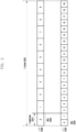
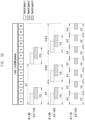
- FIG. 2 illustrates structures of a frame, a subframe, and a slot in a wireless communication system according to an embodiment of the present disclosure.
- One frame 200 may be 10 ms.
- One subframe 201 may be 1 ms, and thus the one frame 200 may be configured by a total of ten subframes 201.
- One subframe 201 may include one or multiple slots 202 and 203, and the number of slots 202 and 203 per one subframe 201 may differ according to configuration value p 204 or 205 for a subcarrier spacing.
- configuration value p 204 or 205 for a subcarrier spacing.
- each subcarrier spacing configuration ⁇ , N slot subframe , ⁇ and N slot frame , ⁇ may be defined as in Table 1 below. [Table 1] ⁇ N symb slot N slot frame , ⁇ N slot subframe , ⁇ 0 14 10 1 1 14 20 2 2 14 40 4 3 14 80 8 4 14 160 16 5 14 320 32
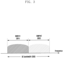
- FIG. 3 illustrates an example of the configuration of BWP in a wireless communication system according to an embodiment of the present disclosure.
- a LTE bandwidth 300 is configured by two BWPs, that is, BWP #1 301 and BWP #2 302.
- the base station may configure one or multiple BWPs for the UE, and may configure pieces of information as shown in Table 2 below for each BWP.
- An embodiment of the present disclosure is not limited to the above example, and in addition to the configuration information, various parameters related to a BWP may be configured in the UE and some pieces of information may be omitted.
- the pieces of information may be transmitted by the base station to the LTE via higher layer signaling, for example, radio resource control (RRC) signaling.
- RRC radio resource control
- At least one BWP among the configured one or multiple BWPs may be activated. Whether to activate the configured BWP may be semi-statically transmitted from the base station to the LTE via RRC signaling or may be dynamically transmitted through downlink control information (DCI).
- DCI downlink control information
- the LTE before RRC connection may be configured with an initial BWP for initial access from a base station through a master information block (MIB). More specifically, the LTE may receive configuration information about a search apace and a control resource set (CORESET) through which the PDCCH for reception of system information used for initial access (which may correspond to remaining system information (RMSI) or system information block 1 (SIB 1)) may be transmitted through the MIB in an initial access operation.
- the CORESET and search space, which are configured through the MIB may be regarded as identity (ID) 0, respectively.
- the base station may notify the UE of configuration information, such as frequency allocation information, time allocation information, and numerology for the control resource set #0 through the MIB.
- the base station may notify the LTE of configuration information regarding the monitoring periodicity and occasion for the control resource set #0, that is, configuration information regarding the search space #0, through the MIB.
- the LTE may regard the frequency domain configured as the control resource set #0, obtained from the MIB, as an initial BWP for initial access.
- the ID of the initial BWP may be regarded as zero.
- the configuration of the BWP supported by 5G may be used for various purposes.
- a case in which a bandwidth supported by the UE is less than a system bandwidth may be supported through the BWP configuration.
- the base station configures, in the LTE, a frequency location (configuration information 2) of the BWP to enable the LTE to transmit or receive data at a specific frequency location within the system bandwidth.
- the base station may configure multiple BWPs in the UE for the purpose of supporting different numerologies. For example, in order to support both data transmission/reception to/from a predetermined UE by using a subcarrier spacing of 15 kHz and a subcarrier spacing of 30 kHz, two BWPs may be configured to use a subcarrier spacing of 15 kHz and a subcarrier spacing of 30 kHz, respectively. Different BWPs may be frequency division multiplexed, and when attempting to transmit or receive data at a specific subcarrier spacing, the BWP configured with the corresponding subcarrier spacing may be activated.
- the base station may configure, in the LTE, the BWPs having bandwidths of different sizes for the purpose of reducing power consumption of the LTE.
- the LTE supports a very large bandwidth, for example, a bandwidth of 100 MHz, and always transmits or receives data at the corresponding bandwidth
- the transmission or reception may cause very high power consumption in the LTE.
- the UE performs monitoring on an unnecessary downlink control channels of a large bandwidth of 100 MHz even when there is no traffic, the monitoring may be very inefficient in terms of power consumption.
- the base station may configure, for the LTE, a BWP of a relatively small bandwidth, for example, a BWP of 20 MHz.
- the UE may perform a monitoring operation on a BWP of 20 MHz.
- the UE may transmit or receive data in a BWP of 100 MHz according to an indication of the base station.
- the LTEs before the RRC connection may receive configuration information about the initial bandwidth part through the MIB in the initial connection operation. More specifically, the UE may be configured with a CORESET for a downlink control channel through which DCI for scheduling a SIB may be transmitted from a MIB of a physical broadcast channel (PBCH). The bandwidth of the control resource set configured through the MIB may be regarded as the initial BWP. The UE may receive, through the configured initial BWP, a PDSCH through which the SIB is transmitted. The initial BWP may be used for other system information (OSI), paging, and random access as well as the reception of the SIB.
- OSI system information
- paging paging
- random access as well as the reception of the SIB.
- a base station may indicate the LTE to change (or switching, transition) the BWP by using a bandwidth part indicator field in DCI.
- the base station may indicate BWP #2 302 to the LTE by using the BWP indicator in DCI, and the LTE may perform a BWP switch to the BWP #2 302 indicated by the BWP indicator in the received DCI.
- the UE since the DCI-based BWP change may be indicated by the DCI scheduling the PDSCH or PUSCH, when receiving a request to switch the BWP, the UE should smoothly receive or transmit the PDSCH or PUSCH, which is scheduled by the DCI, without difficulty in the switched BWP.
- T BWP delay time
- the UE may report a BWP delay time type that is supportable to the base station.
- the LTE may complete a switch to a new BWP indicated by the BWP switch indicator at a time not later than slot n+T BWP , and may perform transmission and reception with respect to a data channel scheduled by the corresponding DCI in the switched new BWP.
- the base station may determine a time domain resource assignment for the data channel by considering the BWP switch delay time (T BWP ) of the LTE.
- the base station may schedule the corresponding data channel after the BWP switch delay time according to the method for determining time domain resource assignment for the data channel. Therefore, the UE may not expect the DCI indicating the BWP switch to indicate a slot offset (K0 or K2) value less than the T BWP .
- the UE may not perform transmission or reception during a time interval from a third symbol of the slot in which the PDCCH including the DCI is received to a start time of the slot indicated by the slot offset (K0 or K2) value indicated by the time domain resource allocation indicator field in the DCI. For example, if the UE has received the DCI indicating the BWP switch in slot n and the slot offset value indicated by the DCI is K, the UE may not perform transmission or reception from the third symbol of the slot n to the symbol prior to slot n+K (i.e., the last symbol of slot n+K-1).
- the DCI for example, DCI format 1_1 or 0_1
- K2 start time of the slot indicated by the slot offset
- the SS/PBCH block may refer to a physical layer channel block including a primary SS (PSS), a secondary SS (SSS), and a PBCH.
- PSS primary SS
- SSS secondary SS
- PBCH PBCH
- the UE may detect the PSS and the SSS in the initial access operation, and may decode the PBCH.
- the UE may obtain the MIB from the PBCH, and may be configured with the CORESET #0 (which may correspond to the control resource set having the CORESET index of 0) therefrom.
- the LTE may monitor the control resource set #0 under the assumption that a demodulation reference signal (DMRS) transmitted in the selected SS/PBCH block and the control resource set #0 is quasi-co-located (QCLed).
- DMRS demodulation reference signal
- the UE may receive system information based on downlink control information transmitted from the control resource set #0.
- the UE may obtain, from the received system information, configuration information related to a RACH used for initial access.
- the UE may transmit a physical RACH (PRACH) to the base station by considering the selected SS/PBCH index, and the base station having received the PRACH may obtain information about an SS/PBCH block index selected by the LTE.
- the base station may know which block is selected among the SS/PBCH blocks by the LTE, and may know that the control resource set #0 associated therewith is monitored.
- FIG. 6 illustrates a discontinuous reception (DRX) operation in a wireless communication system according to an embodiment of the present disclosure.
- DRX is an operation in which the LTE that is using a service discontinuously receives data in an RRC connected state in which a radio link is established between the base station and the LTE.
- the LTE turns on a receiver at a specific time point to monitor a control channel and turns off the receiver when no data is received during a predetermined period, and thus the power consumption of the UE may be reduced.
- the DRX operation may be controlled by an MAC layer device based on various parameters and a timer.
- an active time 605 is a time when the LTE wakes up every DRX cycle and monitors the PDCCH.
- the active time 605 may be defined as follows.
- the DRX cycle refers to a cycle in which the LTE wakes up and monitors the PDCCH. That is, the DRX cycle refers to on duration occurrence period or a time interval until the UE monitors the PDCCH and then monitors the next PDCCH.
- DRX cycles There are two types of DRX cycles, that is, short DRX cycle and long DRX cycle. The short DRX cycle may be optionally applied.
- a long DRX cycle 625 is a longer cycle between the two DRX cycles configured in the LTE.
- the LTE starts the drx-onDurationTimer 615 again at a time point at which the long DRX cycle 625 has elapsed from the start point (e.g., start symbol) of the drx-onDurationTimer 615 while operating in long DRX.
- the UE may start the drx-onDurationTimer 615 in a slot after drx-SlotOffset in a subframe satisfying Equation 1 below.
- the drx-SlotOffset refers to a delay before the start of the drx-onDurationTimer 615.
- drx-LongCycleStartOffset may be used to define a subframe to start the long DRX cycle 625.
- the drx-LongCycleStartOffset may be configured as, for example, the time, the number of subframes, the number of slots, and the like.
- scheduling information about uplink data (or physical uplink shared channel (PUSCH)) or downlink data (or physical downlink shared channel (PDSCH)) is transmitted from a base station to a LTE through the DCI.
- the UE may monitor a fallback DCI format and a non-fallback DCI format with regard to the PUSCH or the PDSCH.
- the fallback DCI format may include a fixed field predefined between the base station and the LTE, and the non-fallback DCI format may include a configurable field.
- the DCI may be transmitted through a physical downlink control channel (PDCCH) after channel coding and modulation is performed thereon.
- a cyclic redundancy check (CRC) may be attached to a DCI message payload, and the CRC may be scrambled by a radio network temporary identifier (RNTI) corresponding to the identification information of the LTE.
- RNTI radio network temporary identifier
- Different RNTIs may be used according to the purpose of the DCI message, for example, a LTE-specific data transmission, a power adjustment command, or a random access response. That is, the RNTI is not explicitly transmitted, but is included in a CRC calculation process and then transmitted.
- the UE may check a CRC by using an assigned RNTI. When a CRC check result is correct, the UE may know that the corresponding message has been transmitted to the LTE.
- DCI for scheduling a PDSCH for system information (SI) may be scrambled by an SI-RNTI.
- DCI for scheduling a PDSCH for a random access response (RAR) message may be scrambled by an RA-RNTI.
- DCI for scheduling a PDSCH for a paging message may be scrambled by a P-RNTI.
- DCI for notifying of a slot format indicator (SFI) may be scrambled by an SFI-RNTI.
- DCI for notifying of transmit power control (TPC) may be scrambled by a TPC-RNTI.
- DCI for scheduling UE-specific PDSCH or PUSCH may be scrambled by a cell RNTI (C-RNTI).
- C-RNTI cell RNTI
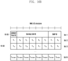
- DCI format 0_0 may be used as a fallback DCI for scheduling a PUSCH.
- a CRC may be scrambled by a C-RNTI.
- the DCI format 0_0 in which the CRC is scrambled by the C-RNTI may include, for example, the following information.
- DCI format 0_1 may be used as a non-fallback DCI for scheduling a PUSCH.
- a CRC may be scrambled by a C-RNTI.
- the DCI format 0_1 in which the CRC is scrambled by the C-RNTI may include, for example, the following information.
- - Modulation and coding scheme - 5 bits - New data indicator - 1 bit - Redundancy version - 2 bits - HARQ process number - 4 bits - 1st downlink assignment index - 1 or 2 bits • 1 bit for semi-static HARQ-ACK codebook; • 2 bits for dynamic HARQ-ACK codebook with single HARQ-ACK codebook.
- DCI format 1_0 may be used as a fallback DCI for scheduling a PDSCH.
- a CRC may be scrambled by a C-RNTI.
- the DCI format 1_0 in which the CRC is scrambled by the C-RNTI may include, for example, the following information.
- DCI format 1_1 may be used as a non-fallback DC for scheduling a PDSCH.
- a CRC may be scrambled by a C-RNTI.
- the DCI format 1_1 in which the CRC is scrambled by the C-RNTI may include, for example, the following information.
- FIG. 4 illustrates an example of a control resource set (CORESET) where a downlink control channel is transmitted in a 5G wireless communication system.
- FIG. 4 shows an example in which a LTE BWP 410 is configured in a frequency domain and two CORESETs (CORESET #1 401 and CORESET #2 402) are configured within one slot 420 in a time domain.
- the CORESETs 401 and 402 may be configured in specific frequency resources 403 within the entire LTE BWP 410 in the frequency domain.
- One or multiple OFDM symbols may be configured in the time domain and defined as a control resource set duration 404.
- the CORESET #1 401 is configured with the control resource set duration of two symbols
- the CORESET #2 402 is configured with the control resource set duration of one symbol.
- the above described CORESET in 5G may be configured for the LTE by the base station via higher layer signaling (e.g., SI, MIB, RRC signaling).
- Configuring the CORESET for the LTE refers to providing information such as a CORESET identity, a frequency location of the CORESET, a symbol length of the CORESET, and the like. For example, it may include the following information.
- tci-StatesPDCCH (simply referred to as transmission configuration indication (TCI) state) configuration information may include information about one or multiple synchronization signal/physical broadcast channel (SS/PBCH) block indices or channel state information reference signal (CSI-RS) indices having a QCL relationship with a DMRS transmitted in the corresponding CORESET.
- TCI transmission configuration indication
- FIG. 5A illustrates an example of the basic unit of time and frequency resources configuring a downlink control channel that can be used in 5G.
- the basic unit of time and frequency resources configuring a control channel may be referred to as a resource element group (REG) 603, which may be defined as one OFDM symbol 501 in a time domain and one physical resource block (PRB) 502, i.e., 12 subcarriers, in a frequency domain.
- the base station may concatenate the REGs 503 to configure a downlink control channel allocation unit.
- REG resource element group
- PRB physical resource block
- one CCE 504 may consist of multiple REGs 503.
- the REG 503 may include 12 REs, and when one CCE 504 consist of six REGs 503, one CCE 504 may include 72 REs.
- the downlink CORESET When the downlink CORESET is configured, it may include multiple CCEs 504.
- a specific downlink control channel may be transmitted after being mapped to one or more CCEs 504 according to an aggregation level (AL) in the CORESET.
- the CCEs 504 in the CORESET are distinguished by numbers.
- the numbers of the CCEs 504 may be assigned according to a logical mapping scheme.
- the basic unit of the downlink control channel shown in FIG. 5A may include both REs to which DCI is mapped and a region to which a DMRS 505 which is a reference signal for decoding the DCI is mapped.
- three DMRSs 505 may be transmitted in one REG 503.
- the number of CCEs used for transmission of the PDCCH may be 1, 2, 4, 8, or 16 according to the AL.
- the LTE should detect a signal in a state in which the LTE does not know information about the downlink control channel, and a search space representing a set of CCEs has been provided for blind decoding.
- the search space is a set of downlink control channel candidates including CCEs that the UE has to attempt to decode at a given AL. Since there are various ALs that make one bundle of 1, 2, 4, 8, or 16 CCEs, the UE may have multiple search spaces.
- a search space set may be defined as a set of search spaces at all configured ALs.
- the search space may be classified into a common search space and a LTE-specific search space.
- a predetermined group of LTEs or all the UEs may examine the common search space of the PDCCH so as to receive cell common control information such as dynamic scheduling of system information or a paging message.
- cell common control information such as dynamic scheduling of system information or a paging message.
- PDSCH scheduling allocation information for transmission of the SIB including cell operator information and the like may be received by examining the common search space of the PDCCH.
- the common search space since a predetermined group of LTEs or all the LTEs need to receive the PDCCH, the common search space may be provided as a set of previously appointed CCEs.
- Scheduling allocation information about the UE-specific PDSCH or PUSCH may be received by examining the UE-specific search space of the PDCCH.
- the UE-specific search space may be LTE-specifically provided as a function of the LTE identity and various system parameters.
- the parameter for the search space of the PDCCH may be configured for the UE by the base station via higher layer signaling (e.g., SIB, MIB, RRC signaling, etc.).
- the base station may configure, for the UE, the number of PDCCH candidates at each aggregation level L, the monitoring periodicity for the search space, the monitoring occasion of symbol units in the slots for the search space, the search space type (common search space or LTE-specific search space), the combination of RNTI and DCI format to be monitored in the search space, the control resource set index to monitor the search space, and the like.
- it may include the following information.
- the base station may configure one or more search space sets for the LTE according to configuration information. According to some embodiments, the base station may configure search space set 1 and search space set 2 in the LTE. The base station may configure the search space set 1 in the LTE so that DCI format A scrambled by an X-RNTI is monitored in the common search space. The base station may configure the search space set 2 in the LTE so that DCI format B scrambled by a Y-RNTI is monitored in the UE-specific search space.
- one or multiple search space sets may exist in the common search space or the UE-specific search space.
- search space set #1 and search space set #2 may be configured as the common search space
- search space set #3 and search space set #4 may be configured as the UE-specific search space.
- the present disclosure is not limited to below.
- the following combinations of the DCI format and the RNTI may be monitored.
- the present disclosure is not limited to below.
- the specified RNTIs may follow the definitions and usages described below.
- the search space of the aggregation level L in the CORESET p and the search space set s may be expressed by Equation 2 below.
- the Y p,ns,f ⁇ value may correspond to zero in the common search space.
- the Y p,ns,f ⁇ value may correspond to a value that changes according to the LTE identity (C-RNTI or ID configured by the base station for the LTE) and the time index.
- multiple search space sets may be configured with different parameters (e.g., parameters in Table 9), and accordingly, the set of search space sets monitored by the UE may differ at each time point. For example, if search space set #1 is configured with the X-slot period, search space set #2 is configured with the Y-slot period, and X and Y are different, the LTE may monitor both search space set #1 and space set #2 in a specific slot, and may monitor one of search space set #1 and search space set #2 in a specific slot.
- parameters in Table 9 e.g., parameters in Table 9
- a UE may perform, for each subcarrier spacing, UE capability reporting for a case of having multiple PDCCH monitoring occasions in a slot, and in this case, the term span may be used.
- Span denotes consecutive symbols in which the LTE can monitor a PDCCH in the slot, and each PDCCH monitoring occasion is within one span.
- Span may be expressed as (X,Y), where x denotes the minimum number of symbols that should be separated between the first symbols of two consecutive spans, and Y denotes the number of consecutive symbols in which the LTE can monitor the PDCCH within one span.
- the UE may monitor the PDCCH in an interval from the first symbol of the span to the Y symbol within the span.
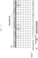
- FIG. 5B illustrates, through a span, a case where a LTE may have a plurality of PDCCH monitoring occasions within a slot in a wireless communication system.
- (5-1-00) represents a case in which two spans that can be expressed by (7,4) exist in a slot.
- the slot position in which the above-described common search space and LTE-specific search space are located is indicated by the monitoringSlotPeriodicityAndOffset parameter in Table 11-1, and the symbol position in a slot is indicated by a bitmap through the monitoringSymbolsWithinSlot parameter in Table 9.
- the symbol position in a slot in which the LTE can monitor the search space may be reported to the base station through the following LTE capabilities.
- UE capability 1 (hereinafter, referred to as FG 3-1).
- This UE capability denotes, as shown in Table 11-1 below, if one monitoring occasion (MO) for the type 1 and type 3 common search space or LTE-specific search space exists in a slot, UE capability capable of monitoring the MO when the corresponding MO occasion is located within the first 3 symbols in a slot.
- This LTE capability is a mandatory capability that all LTEs supporting NR should support, and whether this capability is supported is not explicitly reported to the base station.
- the monitoring occasion is within the first 3 OFDM symbols of a slot -
- the monitoring occasion can be any OFDM symbol(s) of a slot, with the monitoring occasions for any of Type 1- CSS without dedicated RRC configuration, or Types 0, 0A, or 2 CSS configurations within a single span of three consecutive OFDM symbols within a slot 3)
- Number of PDCCH blind decodes per slot with a given SCS follows Case 1-1 table 5) Processing one unicast DCI scheduling DL and one unicast DCI scheduling UL per slot per scheduled CC for FDD 6) Processing one unicast DCI scheduling DL and 2 unicast DCI scheduling UL per slot per scheduled CC for TDD
- UE capability 2 (hereinafter, referred to as FG 3-2).
- This UE capability denotes, as shown in Table 11-2 below, if a monitoring occasion (MO) for a common search space or a LTE-specific search space exists in a slot, UE capability capable of monitoring regardless of the location of the start symbol of the MO.
- This LTE capability may be optionally supported by the LTE, and whether this capability is supported is explicitly reported to the base station.
- this LTE capability indicates a pattern of a MO that the UE can monitor when multiple MOs for a common search space or a UE-specific search space exist in a slot.
- the above-described pattern includes an interval X between start symbols between different MOs, and a maximum symbol length Y for one MO.
- the combination of (X,Y) supported by the UE may be one or multiple ⁇ (2,2), (4,3), and (7,3) ⁇ .
- This LTE capability is optionally supported by the UE, and whether this capability is supported and a combination of (X, Y) described above are explicitly reported to the base station.
- monitoring occasion can be any OFDM symbol(s) of a slot for Case 2
- monitoring occasion can be any OFDM symbol(s) of a slot for Case 2 pdcch-MonitoringAnyOccasions ⁇ 3-5. withoutDCI-Gap 3-5a.
- monitoring occasion can be any OFDM symbol(s) of a slot for Case 2 with a DCI gap
- monitoring occasion can be any OFDM symbol(s) of a slot for Case 2, with minimum time separation (including the cross-slot boundary case) between two DL unicast DCIs, between two UL unicast DCIs, or between a DL and an UL unicast DCI in different monitoring occasions where at least one of them is not the monitoring occasions of FG-3-1, for a same UE as - 2OFDM symbols for 15kHz - 4OFDM symbols for 30kHz - 7OFDM symbols for 60kHz with NCP - 11OFDM symbols for 120kHz Up to one unicast DL DCI and up to one unicast UL DCI in a monitoring occasion except for the monitoring occasions of FG 3-1
- All PDCCH monitoring occasion can be any OFDM symbol(s) of a slot for Case 2 with a span gap PDCCH monitoring occasions of FG-3-1, plus additional PDCCH monitoring occasion(s) can be any OFDM symbol(s) of a slot for Case 2, and for any two PDCCH monitoring occasions belonging to different spans, where at least one of them is not the monitoring occasions of FG-3-1, in same or different search spaces, there is a minimum time separation of X OFDM symbols (including the cross-slot boundary case) between the start of two spans, where each span is of length up to Y consecutive OFDM symbols of a slot.
- the span duration is max ⁇ maximum value of all CORESET durations, minimum value of Y in the LTE reported candidate value ⁇ except possibly the last span in a slot which can be of shorter duration.
- a particular PDCCH monitoring configuration meets the LTE capability limitation if the span arrangement satisfies the gap separation for at least one (X, Y) in the LTE reported candidate value set in every slot, including cross slot boundary.
- the number of different start symbol indices of PDCCH monitoring occasions per slot including PDCCH monitoring occasions of FG-3-1 is no more than 7.
- the number of different start symbol indices of PDCCH monitoring occasions per half-slot including PDCCH monitoring occasions of FG-3-1 is no more than 4 in SCell.
- the UE may report whether the above-described LTE capability 2 and/or LTE capability 3 is supported, and related parameters to the base station.
- the base station may perform time-domain resource allocation for the common search space and the UE-specific search space based on the reported LTE capability.
- the base station may the base station may prevent the MO from being located in a non-monitoring position of the UE.
- search space sets are configured for a LTE
- the following conditions may be considered in a method for determining a search space set configured to be monitored by the UE.
- the UE defines the number of PDCCH candidates that can be monitored and the maximum value of the number of CCEs configuring the entire search space (here, the entire search space refers to the entire CCE set corresponding to a union area of multiple search space sets) for each slot. Further, if the value of monitoringCapabilityConfig-r16 is configured with r16monitoringcapability, the UE defines the number of PDCCH candidates that can be monitored and the maximum value of the number of CCEs configuring the entire search space (here, the entire search space refers to the entire CCE set corresponding to the union area of multiple search space sets) for each span.
- M ⁇ which is the maximum number of PDCCH candidate groups that the UE can monitor
- M ⁇ may follow Table 12-1 below if it is defined on a slot basis in a cell configured with a subcarrier spacing of 15 ⁇ 2 ⁇ kHz, and may follow Table 12-2 below if it is defined on a span basis.
- Table 12-1 ⁇ Maximum number of PDCCH candidates per slot and per serving cell (M ⁇ ) 0 44 1 36 2 22 3 20
- C ⁇ which is the maximum number of CCEs configuring the entire search space (here, the entire search space denotes the entire set of CCEs corresponding to the union region of multiple search space sets), may follow Table 12-3 below if it is defined on a slot basis in a cell configured with a subcarrier spacing of 15 ⁇ 2 ⁇ kHz, and may follow Table 17 below if it is defined on a span basis.
- condition A a situation in which both conditions 1 and 2 are satisfied at a specific time point is referred to as "condition A”. Therefore, not satisfying the condition A may refer to not satisfying at least one of the above conditions 1 and 2.
- the case in which the condition A is not satisfied at a specific time point may occur. If the condition A is not satisfied at a specific time point, the UE may select and monitor some of the search space sets configured to satisfy the condition A at the corresponding time point, and the base station may transmit PDCCH to the selected search space sets.
- a method of selecting some search spaces in the entire configured search space set may conform to the following method.
- the LTE may select a search space set, in which a search space type is configured to be a common search space, from among search space sets existing at a corresponding time point, preferentially over a search space set in which a search space type is configured to be a UE-specific search space.
- the LTE may select the search space sets configured to have LTE-specific search spaces.
- a search space set having a low search space set index may have a higher priority.
- the UE-specific search space sets may be selected within a range in which the condition A is satisfied.
- one or more different antenna ports may be associated with each other by a quasi-co-location (QCL) configuration as shown in Table 13 below.
- the TCI state is for announcing a QCL relationship between a PDCCH (or PDCCH DMRS) and another RS or channel, and a certain reference antenna port A (reference RS #A) and another target antenna port B (target RS #B) are QCLed denotes that the UE is allowed to apply some or all of the large-scale channel parameters estimated from the antenna port A to the channel measurement from the antenna port B.
- QCL is used to correlate different parameters, depending on situations, such as 1) time tracking affected by average delay and delay spread, 2) frequency tracking affected by Doppler shift and Doppler spread, 3) radio resource management (RRM) affected by average gain, and 4) beam management (BM) affected by spatial parameters.
- RRM radio resource management
- BM beam management
- the spatial RX parameter may collectively refer to some or all of various parameters, such as angle of arrival (AoA), power angular spectrum (PAS) of AoA, angle of departure (AoD), PAS of AoD, transmit/receive channel correlation, transmit/receive beamforming, and spatial channel correlation.
- AoA angle of arrival
- PAS power angular spectrum
- AoD angle of departure
- PAS PAS of AoD
- transmit/receive channel correlation transmit/receive beamforming
- spatial channel correlation such as transmit/receive channel correlation, transmit/receive beamforming, and spatial channel correlation.
- the QCL relationship can be configured for the UE through the RRC parameters TCI-State and QCL-Info as shown in Table 14 below.
- the base station configures one or more TCI states for the UE and informs the LTE of up to two QCL relationships (qcl-Type1, qcl-Type2) for RS referring to the ID of the TCI state, that is, target RS.
- pieces of QCL information (QCL-Info) included in each TCI state include the serving cell index and BWP index of the reference RS indicated by the corresponding QCL information, the type and ID of the reference RS, and the QCL type as shown in Table 13 above.
- FIG. 7 illustrates an example of base station beam allocation according to TCI state configuration.
- Tables 15-1 to 15-5 below show valid TCI state configurations according to target antenna port types.
- Table 15-1 shows valid TCI state configuration when the target antenna port is CSI-RS for tracking (TRS).
- TRS refers to an NZP CSI-RS, in which a repetition parameter is not configured and trs-Info is configured to be true, among CSI-RSs.
- Configuration 3 in Table 15-1 may be used for aperiodic TRS.
- Table 15-2 shows valid TCI state configuration when the target antenna port is CSI-RS for CSI.
- the CSI-RS for CSI refers to an NZP CSI-RS, in which a parameter indicating repetition (e.g., a repetition parameter) is not configured and trs-Info is not configured to be true, among CSI-RSs.
- Table 15-3 shows a valid TCI state configuration when a target antenna port is CSI-RS for beam management (BM, which has the same meaning as CSI-RS for L1 RSRP reporting).
- BM CSI-RS for beam management
- the CSI-RS for BM denotes an NZP CSI-RS, in which a repetition parameter is configured and has the value of On or Off, and trs-Info is not configured to be true, among CSI-RSs.
- Table 15-4 shows valid TCI state configuration when a target antenna port is a PDCCH DMRS.
- QCL-TypeD 2 TRS QCL-TypeA CSI-RS (BM)
- QCL-TypeD 3 CSI-RS (CSI)
- QCL-TypeA CSI-RS (same as DL RS 1)
- Table 15-5 shows a valid TCI state configuration when the target antenna port is a PDSCH DMRS.
- a target antenna port and a reference antenna port for each stage are configured to be "SSB" -> "TRS” -> "CSI-RS for CSI, or CSI-RS for BM, PDCCH DMRS, or PDSCH DMRS". Accordingly, it is possible to link the statistical characteristics that can be measured from the SSB and the TRS to each of antenna ports to assist the reception operation of a LTE.
- TCI state combinations applicable to a PDCCH DMRS antenna port are shown in Table 16 below.
- Table 16 the fourth row is a combination assumed by the LTE before RRC configuration, and configuration after RRC is not possible.
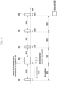
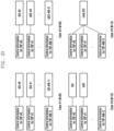
- a base station may configure N TCI states 805, 810, ... , 820 for a LTE via RRC signaling 800, and may configure some of them as TCI states for a CORESET (825). Thereafter, the base station may indicate one of the TCI states 830, 835, and 840 for the CORESET to the LTE via MAC CE signaling (845). Thereafter, the UE may receive a PDCCH based on beam information included in a TCI state indicated by the MAC CE signaling.
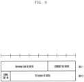
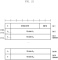
- FIG. 9 illustrates a TCI indication MAC CE signaling structure for the PDCCH DMRS.
- the TCI indication MAC CE signaling for the PDCCH DMRS consists of 2 bytes (16 bits), and may include a serving cell ID 915 of 5 bits, a CORESET ID 920 of 4 bits, and a TCI state ID 925 of 7 bits.
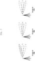
- FIG. 10 illustrates an example of control resource set (CORESET) and search space beam configuration according to the above description.
- a base station may indicate one TCI state in a list of TCI states included in a CORESET 1000 configuration through MAC CE signaling (1005). Thereafter, before another TCI state is indicated to the corresponding CORESET through another MAC CE signaling, the UE considers that the same QCL information (beam #1) 1005 is applied to one or more search spaces 1010, 1015, and 1020 connected to the CORESET.
- beam #1 QCL information
- Embodiments below provide a more flexible PDCCH beam configuration and management method.
- several distinguished examples are provided for convenience of description, but these are not mutually exclusive and can be applied by appropriately combining with each other depending on the situation.
- the base station may configure, in the UE, one or multiple TCI states for a specific control resource set, and may activate one of the configured TCI states through a MAC CE activation command.
- ⁇ TCI state #0, TCI state #1, and TCI state #2 ⁇ are configured as the TCI state in the CORESET #1, and the base station may transmit, to the LTE, a command of activating to assume the TCI state #0 as the TCI state for the CORESET #1 through the MAC CE.
- the UE may correctly receive the DMRS of the corresponding CORESET based on QCL information in the activated TCI state.
- the UE may assume that DMRS transmitted in the CORESET #0 is QCLed with an SS/PBCH block identified during the initial access procedure or non-contention-based random access procedure that is not triggered by a PDCCH command.
- the UE may assume that DMRS transmitted in the CORESET #X is QCLed with an SS/PBCH block identified during the initial access procedure.
- the QCL priority determination operation for PDCCH will be described in detail.
- the UE may select a specific CORESET according to the QCL prioritization operation and monitor CORESETs having the same QCL-TypeD characteristics as the corresponding CORESET. That is, when a plurality of CORESETs overlap in time, the LTE may receive one QCL-TypeD characteristic.
- the criteria for determining the QCL priority may be as follows.
- Criterion 1 A CORESET connected to a common search space of the lowest index in a cell corresponding to the lowest index among cells including the common search space.
- Criterion 2 A CORESET connected to a UE-specific search space of the lowest index in a cell corresponding to the lowest index among cells including the UE-specific search space.
- any criterion is not satisfied, another criterion is applied. For example, in the case where CORESETs overlap in time in a specific PDCCH monitoring occasion, if all CORESETs are not connected to a common search space but to a UE-specific search space, that is, if criterion 1 is not satisfied, the UE may omit application of criterion 1 and apply criterion 2.
- the LTE selects a CORESET according to the above-mentioned criteria, the following two matters may be additionally considered for QCL information configured in the CORESET.
- CORESET 1 has CSI-RS 1 as a reference signal having a QCL-TypeD relationship
- a reference signal in which the CSI-RS 1 has a QCL-TypeD relationship is SSB 1
- a reference signal in which another CORESET 2 has a QCL-TypeD relationship is SSB 1
- the UE may consider that the two CORESETs 1 and 2 have different QCL-TypeD characteristics.
- CORESET 1 has CSI-RS 1 configured in cell 1 as a reference signal having a QCL-TypeD relationship, and a reference signal in which the CSI-RS 1 has a QCL-TypeD relationship is SSB 1
- CORESET 2 has CSI-RS 2 configured in cell 2 as a reference signal having a QCL-TypeD relationship, and a reference signal in which the CSI-RS 2 has a QCL-TypeD relationship is SSB 1
- the UE may consider that the two CORESETs have the same QCL-TypeD characteristic.
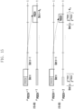
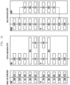
- FIG. 12 illustrates a method in which a LTE selects a receivable CORESET by considering a priority when receiving a downlink control channel in a wireless communication system according to an embodiment of the present disclosure.
- the UE may be configured to receive a plurality of control resource sets overlapping in time in a specific PDCCH monitoring occasion 1210, and these plurality of CORESETs may be connected to a common search space or a UE-specific search space for a plurality of cells.
- CORESET #1 1215 connected to common search space #1 may exist, and within BWP #1 1205 of cell #2, CORESET #1 1220 connected to common search space #1 and CORESET #2 1225 connected to UE-specific search space #2 may exist.
- the CORESETs 1215 and 1220 have a QCL-TypeD relationship with CSI-RS resource #1 configured in BWP #1 of the cell #1, and the CORESET 1225 may have a QCL-TypeD relationship with CSI-RS resource #1 configured in BWP #1 of the cell #2.
- the UE may receive all other CORESETs having the same QCL-TypeD reference signal as that of the CORESET #1 1215. Accordingly, the UE may receive the CORESETs 1215 and 1220 in the corresponding PDCCH monitoring occasion 1210.
- the UE may be configured to receive a plurality of CORESETs overlapping in time in a specific PDCCH monitoring occasion 1240, and these plurality of CORESETs may be connected to a common search space or LTE-specific search space for a plurality of cells.
- CORESET #1 1245 connected to the UE-specific search space #1 and CORESET #2 connected to the UE-specific search space #2 1250 may exist, and within BWP #1 1235 of the cell #2, CORESET #1 1255 connected to the UE-specific search space #1 and CORESET #2 1260 connected to the UE-specific search space #3 may exist.
- the CORESETs 1245 and 1250 may have a QCL-TypeD relationship with the CSI-RS resource #1 configured in BWP #1 of the cell #1
- CORESET 1255 may have a QCL-TypeD relationship with the CSI-RS resource #1 configured in BWP #1 of the cell #2
- the CORESET 1260 may have a QCL-TypeD relationship with the CSI-RS resource #2 configured in BWP #1 of the cell #2.
- the criterion 1 is applied to the corresponding PDCCH monitoring occasion 1240, there is no common search space, and thus the criterion 2 which is the next criterion may be applied.
- the UE may receive all other CORESETs having the same QCL-TypeD reference signal as that of the CORESET 1245. Accordingly, the UE may receive the CORESETs 1245 and 1250 in the corresponding PDCCH monitoring occasion 1240.
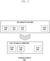
- a rate matching or puncturing operation may be considered as the transmission/reception operation of channel A in consideration of resource C corresponding to a region in which the resource A and the resource B overlap.
- a specific operation may follow, further to the details below.
- a base station may map the channel A to the remaining resource regions except for resource C among the entire resource A for transmission of symbol sequence A to a LTE, the resource C corresponding to a region in which the resource B overlap the resource A, and transmit the same.
- the base station may sequentially map the symbol sequence A to ⁇ resource #1, resource #2, resource #4 ⁇ , which are the remaining resources except for ⁇ resource #3 ⁇ corresponding to the resource C among the resource A, and transmit the same.
- the base station may map the symbol sequence ⁇ symbol #1, symbol #2, symbol #3 ⁇ to ⁇ resource #1, resource #2, resource #4 ⁇ , respectively, and transmit the same.
- the UE may determine the resource A and the resource B through scheduling information for symbol sequence A from a base station, and accordingly, the UE may determine resource C corresponding to a region where the resource A and the resource B overlap.
- the LTE may receive the symbol sequence A based on that the symbol sequence A is mapped to the remaining regions except for the resource C among the entire resource A and transmitted.
- the UE may receive the symbol sequence A based on an assumption that the symbol sequence A is sequentially mapped to the remaining resources ⁇ resource #1, resource #2, resource #4 ⁇ except for ⁇ resource #3 ⁇ corresponding to the resource C among the resource A.
- the LTE assumes that the symbol sequence ⁇ symbol #1, symbol #2, symbol #3 ⁇ are mapped to ⁇ resource #1, resource #2, resource #4 ⁇ , respectively, and transmitted, and may perform a subsequent series of reception operations.
- a base station may map the symbol sequence A to the entire resource A. However, the base station may not perform transmission in a resource region corresponding to the resource C, and may perform transmission to the remaining resource regions except for the resource C among the entire resource A.
- the base station may map the symbol sequence A ⁇ symbol #1, symbol #2, symbol #3, symbol #4 ⁇ to the resource A ⁇ resource #1, resource #2, resource #3, resource #4 ⁇ , respectively.
- the base station may transmit the corresponding symbol sequence ⁇ symbol #1, symbol #2, symbol #4 ⁇ to ⁇ resource #1, resource #2, resource #4 ⁇ , which are the remaining resources except for ⁇ resource #3 ⁇ corresponding to the resource C among the entire resource A, and may not transmit ⁇ symbol #3 ⁇ mapped to ⁇ resource #3) corresponding to the resource C.
- the base station may map the symbol sequence ⁇ symbol #1, symbol #2, symbol #4 ⁇ to ⁇ resource #1, resource #2, resource #4 ⁇ , respectively, and transmit the same.
- the LTE may determine the resource A and the resource B through scheduling information for symbol sequence A from the base station, and accordingly, the UE may determine the resource C corresponding to a region where the resource A and the resource B overlap.
- the LTE may receive the symbol sequence Abased on an assumption that the symbol sequence A is mapped to the entire resource A but transmitted in the remaining regions except for the resource C among the resource A.
- the LTE may assume that the symbol sequence A ⁇ symbol #1, symbol #2, symbol #3, symbol 4 ⁇ are mapped to ⁇ resource #1, resource #2, resource #3, resource #4 ⁇ , respectively, and that ⁇ symbol #3 ⁇ mapped to ⁇ resource #3 ⁇ corresponding to resource C is not transmitted, and the LTE may receive the symbol sequence Abased on an assumption that the corresponding symbol sequence ⁇ symbol #1, symbol #2, symbol #4 ⁇ are mapped to ⁇ resource #1, resource #2, resource #4 ⁇ , which are the remaining resources except for ⁇ resource #3 ⁇ corresponding to resource C among resource A, and transmitted. As a result, the LTE assumes that the symbol sequence ⁇ symbol #1, symbol #2, symbol #4 ⁇ are mapped to
- the rate matching refers to controlling the size of a signal by considering the amount of resources capable of transmitting the signal.
- the rate matching of a data channel may be understood as that the size of data is adjusted without mapping and transmitting the data channel with respect to a specific time and frequency resource region.
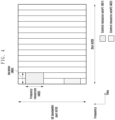
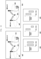
- FIG. 11 illustrates a method in which a base station and a LTE perform data transmission or reception by considering a downlink data channel and a rate matching resource.
- FIG. 11 shows a PDSCH 1101 and a rate matching resource 1102.
- the base station may configure one or more rate matching resources 1102 in the LTE through higher layer signaling (e.g., RRC signaling).
- the configuration information of the rate matching resource 1102 may include time-domain resource allocation information 1103, frequency-domain resource allocation information 1104, and periodicity information 1105.
- a bitmap corresponding to the frequency-domain resource allocation information 1104 is called a first bitmap
- a bitmap corresponding to the time-domain resource allocation information 1103 is called a second bitmap
- a bitmap corresponding to the periodicity information 1105 is called a third bitmap.
- a base station may rate-match the data channel 1101 in the rate matching resource part 1102 and transmit the same.
- the LTE may perform data reception and decoding after assuming that the data channel 1101 has been rate-matched in the rate matching resource part 1102.
- the base station may dynamically notify the LTE of whether the data channel will be rate-matched in the configured rate matching resource part through DCI through an additional configuration (corresponding to a rate matching indicator in the DCI format described above). Specifically, the base station may select some of the configured rate matching resources, may group the selected resources into a rate matching resource group, and may indicate whether the data channel has been rate-matched with each rate matching resource group through DCI using a bitmap method to the UE.
- 5G supports the granularity of "RB symbol level” and "RE level” as a method of configuring the above-described rate matching resource in the LTE, and the following configuration method may be followed.
- the LTE may receive up to four RateMatchPattern for each bandwidth part via higher layer signaling, and one RateMatchPattern may include the following contents.
- a reserved resource in a BWP may include a resource, in which a time and frequency resource region of the corresponding reserved resource is configured as a combination of an RB-level bitmap and a symbol-level bitmap on the frequency axis.
- the reserved resource may span over one or two slots.
- the UE may be additionally configured with a time-domain pattern (periodicityAndPattern) in which the time and frequency domain including a pair of RB level and symbol level bitmaps are repeated.
- a time and frequency domain resource region configured as a CONRESET in a BWP and a resource region corresponding to a time-domain pattern configured as a search space configuration in which the resource region is repeated may be included.
- the LTE may be configured with the following information through higher layer signaling.
- the LTE may determine the location of the CRS in the NR slot corresponding to the LTE subframe based on the above-described information.
- Configuration information for a resource set corresponding to one or multiple zero power (ZP) CSI-RSs in the bandwidth part may be included.
- NR provides a function of configuring a cell specific reference signal pattern of LTE to an NR LTE.
- the CRS pattern may be provided by RRC signaling including at least one parameter in ServingCellConfig information element (IE) or ServingCellConfigCommon IE.
- IE ServingCellConfig information element
- ServingCellConfigCommon IE ServingCellConfigCommon IE
- the parameter may include lte-CRS-ToMatchAround, lte-CRS-PatternList1-r16, lte-CRS-PatternList2-r16, crs-RateMatch-PerCORESETPoolIndex-r16, and the like, for example.
- Rel-15 NR provides a function in which one CRS pattern can be configured per serving cell through the lte-CRS-ToMatchAround parameter.
- the above function has been extended to enable configuration of a plurality of CRS patterns per serving cell.
- one CRS pattern per one LTE carrier may be configured in a single transmission and reception point (TRP) configured LTE, and two CRS patterns per one LTE carrier may be configured in a multi-TRP configured UE.
- TRP transmission and reception point
- two CRS patterns per one LTE carrier may be configured in a multi-TRP configured UE.
- up to three CRS patterns per serving cell may be configured through the lte-CRS-PatternList1-r16 parameter.
- a CRS may be configured for each TRP in the multi-TRP configured LTE.
- a CRS pattern for TRP1 may be configured through the lte-CRS-PatternList1-r16 parameter
- a CRS pattern for TRP2 may be configured through the lte-CRS-PatternList2-r16 parameter.
- whether to apply both the CRS patterns of TRP1 and TRP2 to a specific PDSCH or whether to apply only the CRS pattern for one TRP is determined through crs-RateMatch-PerCORESETPoolIndex-r16 parameter.
- the crs-RateMatch-PerCORESETPoolIndex-r16 parameter is configured to be enabled, only one TRP CRS pattern is applied, and in other cases, both TRP CRS patterns are applied.
- Table 17 shows the ServingCellConfig IE including the CRS pattern
- Table 18 shows the RateMatchPatternLTE-CRS IE including at least one parameter for the CRS pattern.
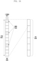
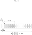
- FIG. 13 illustrates an example of frequency-domain resource allocation of a PDSCH in a wireless communication system according to an embodiment of the present disclosure.
- FIG. 13 shows three frequency-domain resource allocation methods of type 0 (13-00), type 1 (13-05), and dynamic switch (13-10) configurable through a higher layer in an NR wireless communication system.
- some DCI for allocation of PDSCH to the corresponding LTE includes a bitmap formed of non-deterministic random generator (NRBG) bits, with NRBG denoting the number of resource block groups (RBGs) determined further to Table 19 below, according to a BWP size allocated by a BWP indicator and a higher layer parameter rbg-Size, and data is transmitted to RBG indicated as ⁇ 1' in the bitmap.
- NRBG non-deterministic random generator
- some DCI for allocation of the PDSCH to the LTE includes frequency-domain resource allocation information configured by ⁇ log 2 ( N RB DL , BWP N RB DL , BWP + 1 / 2 ⁇ bits.
- the base station may configure a starting VRB 13-20 and the length of frequency-domain resources 13-25 continuously allocated therefrom.
- some DCI for allocation of PDSCH to the LTE includes frequency-domain resource allocation information configured by bits of a greater value 13-35 among a payload 13-15 for configuration of resource type 0 and payloads 13-20 and 13-25 for configuration of resource type 1, a condition for which will be described later.
- one bit is added to the most significant bit (MSB) of the frequency-domain resource allocation information in the DCI, if the corresponding bit has a value of '0', it indicates that resource type 0 is used, and if the corresponding bit has a value of '1', it indicates that resource type 1 is used.
- MSB most significant bit
- next-generation mobile communication system 5G or NR system
- a base station may configure, for a UE, a table for time-domain resource allocation information for a downlink data channel (PDSCH) and an uplink data channel (PUSCH) via higher layer signaling (e.g., RRC signaling).
- PDSCH downlink data channel
- PUSCH uplink data channel
- higher layer signaling e.g., RRC signaling
- the time-domain resource allocation information may include PDCCH-to-PDSCH slot timing (corresponding to a time interval in slot units between a time point at which a PDCCH is received and a time point at which a PDSCH scheduled by the received PDCCH is transmitted, and denoted by K0), PDCCH-to-PUSCH slot timing (corresponding to a time interval in slot units between a time point at which a PDCCH is received and a time point at which a PUSCH scheduled by the received PDCCH is transmitted, and denoted by K2), information on the position and length of a start symbol in which the PDSCH or PUSCH is scheduled within a slot, a mapping type of PDSCH or PUSCH, and the like.
- information such as Table 20 or Table 21 below may be transmitted from the base station to the UE.
- the base station may notify one of the entries in the above-described table representing the time-domain resource allocation information to the LTE via L1 signaling (e.g., DCI) (e.g., may be indicated by a ⁇ time-domain resource allocation' field in DCI).
- L1 signaling e.g., DCI
- the LTE may acquire time-domain resource allocation information for the PDSCH or PUSCH based on the DCI received from the base station.
- FIG. 14 illustrates an example of time-domain resource allocation of a PDSCH in a wireless communication system according to an embodiment of the present disclosure.
- a base station may indicate a time-domain position of a PDSCH resource according to a start position 14-00 and a length 14-05 of an OFDM symbol in one slot 14-10 dynamically indicated based on the subcarrier spacing (SCS) ( ⁇ PDSCH , ⁇ PDCCH ) of a data channel and a control channel configured using a higher layer, a scheduling offset (K0) value, and DCI.
- SCS subcarrier spacing
- K0 scheduling offset
- FIG. 15 illustrates an example of time-domain resource allocation according to the subcarrier spacings of a data channel and a control channel in a wireless communication system according to an embodiment of the present disclosure.
- a base station and a LTE may generate a scheduling offset adjusted according to predetermined slot offset K0.
- the subcarrier spacing of the data channel and the subcarrier spacing of the control channel are different (15-05, ⁇ PDSCH ⁇ ⁇ PDCCH )
- the base station and the LTE may generate a scheduling offset adjusted according to the predetermined slot offset K0 based on the subcarrier spacing of the PDCCH.
- the UE may require a PDSCH processing procedure time for reception of the PDSCH by applying transmission methods indicated through DCI (modulation/demodulation and coding indication index (MCS), demodulation reference signal related information, time and frequency resource allocation information, etc.)
- DCI modulation/demodulation and coding indication index
- MCS modulation/demodulation and coding indication index
- the PDSCH processing procedure time is defined in consideration of the above methods.
- the PDSCH processing procedure time of LTE may follow Equation 3 below.
- T proc , 1 N 1 + d 1,1 + d 2 2048 + 144 ⁇ 2 ⁇ ⁇ T c + T ext
- N 1 The number of symbols determined according to numerology ⁇ and LTE processing capability 1 or 2 according to the LTE capability.
- LTE processing capability 1 is reported according to UE capability report (in case of PDSCH processing capability 1)
- N 1 may have the value in Table 22
- LTE processing capability 2 is reported and it is configured via higher layer signaling that LTE processing capability 2 can be used (in case of PDSCH processing capability 2)
- N 1 may have the value in Table 23.
- the numerology ⁇ may correspond to the minimum value among ⁇ PDCCH , ⁇ PDSCH , and ⁇ UL so as to maximize the T proc,1
- ⁇ PDCCH , ⁇ PDSCH , and ⁇ UL may refer to the numerology of a PDCCH for scheduling of a PDSCH, the numerology of the scheduled PDSCH, and the numerology of an uplink channel through which HARQ-ACK is to be transmitted, respectively.
- the last symbol of the PDSCH is the i-th symbol in the slot in which the PDSCH is transmitted, and if i ⁇ 7, d 1,1 is 7-i, otherwise d 1,1 has the value of 0.
- d 2 of the PUCCH having a high priority index may be configured to be a value reported by the UE. Otherwise, d 2 has the value of 0.
- the value of d 1,1 may be determined according to L, which is the number of symbols of the scheduled PDSCH, and d, which is the number of overlapping symbols between a PDCCH scheduling the PDSCH and the scheduled PDSCH, as follows.
- the value of d 1,1 may be determined according to L, which is the number of symbols of the scheduled PDSCH, and d, which is the number of overlapping symbols between a PDCCH scheduling the PDSCH and the scheduled PDSCH, as follows.
- the PDSCH processing time according to LTE processing capability 2 may be applied when the LTE is configured such that processingType2Enabled which is higher layer signaling with regard to the cell to be an enable state.
- the LTE should transmit a valid HARQ-ACK message. That is, the LTE should transmit the PUCCH including HARQ-ACK only when a PDSCH processing time is sufficient. Otherwise, the LTE may not provide the base station with valid HARQ-ACK information corresponding to the scheduled PDSCH.
- the T proc,1 may be used for both normal or extended CP. In case of a PDSCH configured by two PDSCH transmission occasions in one slot, d 1,1 is calculated based on the first PDSCH transmission occasion in the corresponding slot.
- N pdsch which is the PDSCH reception preparation time of the LTE defined for a time interval between the PDCCH and the PDSCH
- a transmission symbol of the corresponding PDSCH may include a DM-RS.
- the scheduled PDSCH may be transmitted after the N pdsch symbol from the last symbol of the PDCCH for which the corresponding PDSCH is scheduled.
- a transmission symbol of the corresponding PDSCH may include a DM-RS.
- FIGS. 16A and 16B illustrate a procedure for beam configuration and activation of a PDSCH.
- a list of TCI states for a PDSCH may be indicated through a higher layer list such as RRC (16-00).
- the list of TCI states may be indicated by, for example, tci-StatesToAddModList and/or tci-StatesToReleaseList in PDSCH-Config IE for each BWP.
- a part of the list of the TCI states may be activated through the MAC-CE (16-20).
- the maximum number of activated TCI states may be determined according to the capability reported by a LTE.
- Reference numeral 16-50 shows an example of a MAC-CE structure for PDSCH TCI state activation/deactivation.
- each field in the MAC CE and values configurable for each field are as follows.
- - Serving Cell ID This field indicates the identity of the Serving Cell for which the MAC CE applies.
- the length of the field is 5 bits. If the indicated Serving Cell is configured as part of a simultaneousTCI-UpdateList1 or simultaneousTCI-UpdateList2 as specified in TS 38.331 [5], this MAC CE applies to all the Serving Cells configured in the set simultaneousTCI-UpdateList1 or simultaneousTCI-UpdateList2, respectively;
- - BWP ID This field indicates a DL BWP for which the MAC CE applies as the codepoint of the DCI bandwidth part indicator field as specified in TS 38.212 [9].
- the length of the BWP ID field is 2 bits.
- This field is ignored if this MAC CE applies to a set of Serving Cells; - T i : If there is a TCI state with TCI-StateId i as specified in TS 38.331 [5], this field indicates the activation/deactivation status of the TCI state with TCI-StateId i, otherwise MAC entity shall ignore the Ti field.
- the Ti field is set to 1 to indicate that the TCI state with TCI-StateId i shall be activated and mapped to the codepoint of the DCI Transmission Configuration Indication field, as specified in TS 38.214 [7].
- the Ti field is set to 0 to indicate that the TCI state with TCI-StateId i shall be deactivated and is not mapped to the codepoint of the DCI Transmission Configuration Indication field.
- the codepoint to which the TCI State is mapped is determined by its ordinal position among all the TCI States with Ti field set to 1, i.e. the first TCI State with T i field set to 1 shall be mapped to the codepoint value 0, second TCI State with Ti field set to 1 shall be mapped to the codepoint value 1 and so on.
- the maximum number of activated TCI states is 8; - CORESET Pool ID: This field indicates that mapping between the activated TCI states and the codepoint of the DCI Transmission Configuration Indication set by field Ti is specific to the ControlResourceSetId configured with CORESET Pool ID as specified in TS 38.331 [5]. This field set to 1 indicates that this MAC CE shall be applied for the DL transmission scheduled by CORESET with the CORESET pool ID equal to 1, otherwise, this MAC CE shall be applied for the DL transmission scheduled by CORESET pool ID equal to 0. If the coresetPoolIndex is not configured for any CORESET, MAC entity shall ignore the CORESET Pool ID field in this MAC CE when receiving the MAC CE. If the Serving Cell in the MAC CE is configured in a cell list that contains more than one Serving Cell, the CORESET Pool ID field shall be ignored when receiving the MAC CE.
- the base station may configure at least one SRS configuration for each uplink BWP in order to transfer configuration information for SRS transmission to the LTE, and may configure at least one SRS resource set for each SRS configuration.
- the base station and the LTE may exchange higher layer signaling information as follows in order to transfer information about the SRS resource set.
- the LTE may understand that the SRS resource included in the set of SRS resource indexes referenced in the SRS resource set follows the information configured in the SRS resource set.
- the base station and the LTE may transmit or receive higher layer signaling information in order to transfer individual configuration information for the SRS resource.
- the individual configuration information for the SRS resource may include time-frequency domain mapping information in a slot of the SRS resource, and this may include information about intra-slot or inter-slot frequency hopping of the SRS resource.
- the individual configuration information for the SRS resource may include the time-domain transmission configuration of the SRS resource, and may be configured as one of ⁇ periodic', ⁇ semi-persistent', and 'aperiodic'. The individual configuration information may be limited to have the same time-domain transmission configuration as the SRS resource set including the SRS resource.
- the SRS resource transmission period and slot offset may be additionally included in the time-domain transmission configuration.
- the base station may activate, deactivate, or trigger SRS transmission to the LTE via higher layer signaling including RRC signaling or MAC CE signaling, or L1 signaling (e.g., DCI).
- the base station may activate or deactivate periodic SRS transmission to the LTE via higher layer signaling.
- the base station may indicate the UE to activate the SRS resource set, in which the resource Type is configured as periodic, via higher layer signaling, and the LTE may transmit the SRS resource referenced in the activated SRS resource set.
- the time-frequency domain resource mapping in a slot of the transmitted SRS resource follows the resource mapping information configured in the SRS resource, and the slot mapping including the transmission period and the slot offset follows the periodicityAndOffset configured in the SRS resource.
- the spatial domain transmission filter applied to the SRS resource to be transmitted may refer to spatial relation info configured in the SRS resource, or may refer to associated CSI-RS information configured in the SRS resource set including the SRS resource.
- the UE may transmit the SRS resource within the uplink BWP activated for the periodic SRS resource activated via higher layer signaling.
- the base station may activate or deactivate semi-persistent SRS transmission to the LTE via higher layer signaling.
- the base station may indicate to activate the SRS resource set through MAC CE signaling, and the LTE may transmit the SRS resource referenced in the activated SRS resource set.
- the SRS resource set activated through MAC CE signaling may be limited to the SRS resource set in which the resource Type is configured to be semi-persistent.
- the time-frequency domain resource mapping in a slot of the SRS resource to be transmitted follows the resource mapping information configured in the SRS resource, and the slot mapping including the transmission period and the slot offset follows the periodicityAndOffset configured in the SRS resource.
- the spatial domain transmission filter applied to the SRS resource to be transmitted may refer to spatial relation info configured in the SRS resource, or may refer to associated CSI-RS information configured in the SRS resource set including the SRS resource. If spatial relation info is configured in the SRS resource, a spatial domain transmission filter may be determined, not based on the configured spatial relation info, but by referring to configuration information for the spatial relation information transferred through MAC CE signaling that activates semi-persistent SRS transmission.
- the LTE may transmit the SRS resource in the uplink BWP activated for the semi-persistent SRS resource activated via higher layer signaling.
- the base station may trigger aperiodic SRS transmission to the LTE through DCI.
- the base station may indicate one of aperiodic SRS resource triggers (aperiodicSRS-ResourceTrigger) through an SRS request field of DCI.
- aperiodicSRS-ResourceTrigger aperiodic SRS resource triggers
- the LTE may understand that the SRS resource set including the aperiodic SRS resource trigger indicated through DCI in the aperiodic SRS resource trigger list, among the configuration information of the SRS resource set, is triggered.
- the UE may transmit the SRS resource referenced in the triggered SRS resource set.
- the time-frequency domain resource mapping in the slot of the SRS resource to be transmitted follows the resource mapping information configured in the SRS resource.
- the slot mapping of the SRS resource to be transmitted may be determined through the slot offset between the PDCCH including DCI and the SRS resource, and the slot offset may refer to the value(s) included in the slot offset set configured in the SRS resource set.
- the slot offset between the PDCCH including DCI and the SRS resource may be applied with a value indicated in the time domain resource assignment field of DCI among the offset value(s) included in the slot offset set configured in the SRS resource set.
- the spatial domain transmission filter applied to the SRS resource to be transmitted may refer to spatial relation info configured in the SRS resource, or may refer to associated CSI-RS information configured in the SRS resource set including the SRS resource.
- the LTE may transmit the SRS resource in the uplink BWP activated for the aperiodic SRS resource triggered through DCI.
- the minimum time interval between the PDCCH including the DCI for triggering the aperiodic SRS transmission and the transmitted SRS may be used.
- the time interval for SRS transmission of the LTE may be the number of symbols between the first symbol to which the SRS resource, which is transmitted first among the transmitted SRS resource(s), is mapped, and the last symbol of the PDCCH including the DCI for triggering aperiodic SRS transmission.
- the minimum time interval may be determined by making reference to PUSCH preparation procedure time used for LTE to prepare PUSCH transmission.
- the minimum time interval may have a different value depending on the usage of the SRS resource set including the transmitted SRS resource.
- the minimum time interval may be determined as an N2 symbol in consideration of the LTE processing capability according to the LTE capability by making reference to the PUSCH preparation procedure time of the UE.
- the minimum time interval is configured to be N2 symbol
- the usage of the SRS resource set is configured as 'nonCodebook' or 'beamManagement'
- the minimum time interval may be determined to be the N2+14 symbol.
- the LTE may transmit the aperiodic SRS, and if the time interval for aperiodic SRS transmission is less than the minimum time interval, the LTE may ignore DCI for triggering the aperiodic SRS.
- the spatial RelationInfo configuration information in Table 25 is allowed to be applied to the beam information of the reference signal and a beam used for the corresponding SRS transmission by referring to one reference signal.
- the configuration of spatialRelationInfo may include information as shown in Table 26 below.
- an SS/PBCH block index, CSI-RS index, or SRS index may be configured as an index of a reference signal to be referenced in order to use beam information of a specific reference signal.
- the higher layer signaling referenceSignal is configuration information indicating which reference signal beam information is to be referred to for the corresponding SRS transmission
- ssb-index denotes the index of the SS/PBCH block
- csi-RS-Index denotes the index of the CSI-RS
- srs denotes the index of the SRS.
- the LTE may apply a reception beam used when receiving the SS/PBCH block corresponding to the ssb-Index as a transmission beam of the corresponding SRS transmission. If the value of the higher layer signaling referenceSignal is configured as 'csi-RS-Index', the LTE may apply a reception beam used when receiving the CSI-RS corresponding to the csi-RS-Index as a transmission beam of the corresponding SRS transmission. If the value of the higher layer signaling referenceSignal is configured as ⁇ srs', the LTE may apply a transmission beam used when transmitting the SRS corresponding to srs as a transmission beam of the corresponding SRS transmission.
- PUSCH transmission may be dynamically scheduled by a UL grant in DCI or may be operated by a configured grant Type 1 or Type 2. Dynamic scheduling indication for PUSCH transmission is possible using DCI format 0_0 or 0_1.
- Configured grant Type 1 PUSCH transmission does not receive a UL grant in DCI, and may be semi-statically configured through reception of configuredGrantConfig including rrc-ConfiguredUplinkGrant of Table 27 via higher layer signaling.
- Configured grant Type 2 PUSCH transmission may be semi-persistently scheduled by UL grant in DCI after reception of configuredGrantConfig that does not include the rrc-ConfiguredUplinkGrant of Table 27 via higher layer signaling.
- configuredGrantConfig which is higher layer signaling of Table 27, except for dataScramblingIdentityPUSCH, txConfig, codebookSubset, maxRank, and scaling of UCI-OnPUSCH, which are provided by pusch-Config of Table 28, which is higher layer signaling.
- the LTE is provided with transformPrecoder in configuredGrantConfig, which is higher layer signaling of Table 27, the LTE applies tp-pi2BPSK in the pusch-Config of Table 28 with regards to PUSCH transmission operated by the configured grant.
- a DMRS antenna port for PUSCH transmission is the same as an antenna port for SRS transmission.
- PUSCH transmission may be based on a codebook-based transmission method and a non-codebook-based transmission method, respectively, depending on whether the value of txConfig in pusch-Config of Table 28, which is higher layer signaling, is 'codebook' or 'nonCodebook'.
- PUSCH transmission may be dynamically scheduled through DCI format 0_0 or 0_1, and may be semi-statically configured by a configured grant. If the LTE is indicated to schedule PUSCH transmission through DCI format 0_0, the LTE performs beam configuration for PUSCH transmission by using pucch-spatialRelationInfoID corresponding to the LTE-specific PUCCH resource corresponding to the minimum ID in the uplink BWP activated in the serving cell, and here, PUSCH transmission is based on a single antenna port. The LTE does not expect scheduling for PUSCH transmission through DCI format 0_0 within a BWP in which the PUCCH resource including the pucch-spatialRelationInfo is not configured. If the LTE is not configured with txConfig in pusch-Config of Table 28, the UE does not expect to be scheduled in DCI format 0_1.
- Codebook-based PUSCH transmission may be dynamically scheduled through DCI format 0_0 or 0_1, and may operate semi-statically by a configured grant.
- the LTE determines a precoder for PUSCH transmission based on an SRS resource indicator (SRI), a transmission precoding matrix indicator (TPMI), and a transmission rank (the number of PUSCH transport layers).
- SRI SRS resource indicator
- TPMI transmission precoding matrix indicator
- a transmission rank the number of PUSCH transport layers.
- the SRI may be given through a field SRS resource indicator in DCI or may be configured through srs-ResourceIndicator, which is higher layer signaling.
- the LTE is configured with at least one SRS resource when transmitting a codebook-based PUSCH, and may be configured with up to two SRS resources.
- the SRS resource indicated by the corresponding SRI denotes an SRS resource corresponding to the SRI among SRS resources transmitted before the PDCCH including the corresponding SRI.
- TPMI and transmission rank may be given through field precoding information and number of layers in DCI, or may be configured through precodingAndNumberOfLayers, which is higher layer signaling.
- TPMI is used to indicate a precoder applied to PUSCH transmission. If the LTE is configured with one SRS resource, the TPMI is used to indicate a precoder to be applied in the configured one SRS resource. If the LTE is configured with multiple SRS resources, the TPMI is used to indicate a precoder to be applied in the SRS resource indicated through the SRI.
- a precoder to be used for PUSCH transmission is selected from an uplink codebook having the same number of antenna ports as the value of nrofSRS-Ports in SRS-Config, which is higher layer signaling.
- the LTE determines a codebook subset based on the TPMI and codebookSubset in pusch-Config, which is higher layer signaling.
- CodebookSubset in pusch-Config, which is higher layer signaling may be configured with one of ⁇ fullyAndPartialAndNonCoherent', 'partialAndNonCoherent', or 'noncoherent' based on the LTE capability reported by the UE to the base station.
- the LTE does not expect that the value of codebookSubset, which is higher layer signaling, is configured to be 'fullyAndPartialAndNonCoherent'.
- the UE does not expect that the value of codebookSubset, which is higher layer signaling, is configured to be 'fullyAndPartialAndNonCoherent' or 'partialAndNonCoherent'.
- the LTE may be configured with one SRS resource set in which the value of usage in the SRS-ResourceSet, which is higher layer signaling, is configured to be 'codebook', and one SRS resource in the corresponding SRS resource set may be indicated through SRI. If multiple SRS resources are configured in the SRS resource set in which the usage value in the SRS-ResourceSet, which is higher layer signaling, is configured to be 'codebook', the LTE expects that the values of nrofSRS-Ports in the SRS-Resource, which is higher layer signaling, are configured to be the same value with respect to all SRS resources.
- the LTE transmits, to the base station, one or multiple SRS resources included in the SRS resource set in which the value of usage is configured to be 'codebook' according to higher layer signaling, and the base station indicates the LTE to perform PUSCH transmission by selecting one of the SRS resources transmitted by the LTE and using transmission beam information of the corresponding SRS resource.
- the SRI is used as information for selection of the index of one SRS resource and is included in the DCI.
- the base station includes, in the DCI, information indicating a rank and a TPMI to be used by the UE for PUSCH transmission. The UE performs PUSCH transmission by using the SRS resource indicated by the SRI and applying a rank indicated based on the transmission beam of the SRS resource and a precoder indicated by the TPMI.
- Non-codebook-based PUSCH transmission may be dynamically scheduled through DCI format 0_0 or 0_1, and may be semi-statically operated by a configured grant.
- the LTE may be scheduled with non-codebook-based PUSCH transmission through DCI format 0_1.
- the LTE may be configured with one connected non-zero power CSI-RS (NZP CSI-RS) resource.
- the LTE may perform calculation of the precoder for SRS transmission by measuring the NZP CSI-RS resource connected to the SRS resource set. If the difference between the last received symbol of the aperiodic NZP CSI-RS resource connected to the SRS resource set and the first symbol of aperiodic SRS transmission in the LTE is less than 42 symbols, the LTE does not expect information on the precoder for SRS transmission to be updated.
- the connected NZP CSI-RS is indicated by SRS request, which is a field in DCI format 0_1 or 1_1.
- SRS request which is a field in DCI format 0_1 or 1_1.
- the connected NZP CSI-RS resource is an aperiodic NZP CSI-RS resource
- the connected NZP CSI-RS exists when the value of the SRS request field in DCI format 0_1 or 1_1 is not '00'. In this case, the DCI should not indicate cross carrier or cross BWP scheduling.
- the corresponding NZP CSI-RS is located in a slot in which a PDCCH including the SRS request field is transmitted.
- TCI states configured via the scheduled subcarrier are not configured to be QCL-TypeD.
- the connected NZP CSI-RS may be indicated through associated CSI-RS in the SRS-ResourceSet, which is higher layer signaling.
- the LTE does not expect that spatialRelation Info, which is higher layer signaling for SRS resource, and associated CSI-RS in SRS-ResourceSet, which is higher layer signaling, are configured together.
- the UE may determine a precoder to be applied to PUSCH transmission and a transmission rank, based on the SRI indicated by the base station.
- the SRI may be indicated through a field SRS resource indicator in DCI or may be configured through srs-ResourceIndicator, which is higher layer signaling.
- an SRS resource indicated by the SRI denotes an SRS resource corresponding to the SRI among SRS resources transmitted before the PDCCH including the SRI.
- the LTE may use one or multiple SRS resources for SRS transmission, and the maximum number of SRS resources that can be simultaneously transmitted in the same symbol in one SRS resource set are determined by LTE capability reported by the LTE to the base station.
- the SRS resources simultaneously transmitted by the LTE occupy the same RB.
- the UE configures one SRS port for each SRS resource. Only one SRS resource set in which the value of usage in the SRS-ResourceSet, which is higher layer signaling, is configured to be 'nonCodebook' can be configured, and up to four SRS resources for non-codebook-based PUSCH transmission can be configured.
- the base station transmits one NZP-CSI-RS connected to the SRS resource set to the UE, and the UE performs calculation of a precoder to be used for transmission of one or multiple SRS resources in the corresponding SRS resource set based on a result of measurement at the time of reception of the NZP-CSI-RS.
- the LTE applies, to the base station, the calculated precoder when transmitting one or multiple SRS resources in the SRS resource set in which usage is configured to be 'nonCodebook', and the base station selects one or multiple SRS resources among the received one or multiple SRS resources.
- the SRI indicates an index capable of expressing one or a combination of multiple SRS resources, and the SRI is included in the DCI.
- the number of SRS resources indicated by the SRI transmitted by the base station may be the number of transmission layers of the PUSCH, and the UE performs PUSCH transmission by applying a precoder applied for SRS resource transmission to each layer.
- the UE may require a PUSCH preparation procedure time for transmission of a PUSCH by applying transmission methods indicated through DCI (transmission precoding method of SRS resource, number of transmission layers, or spatial domain transmission filter).
- the PUSCH preparation procedure time is defined in consideration of the above methods.
- the PUSCH preparation procedure time of LTE may follow Equation 4 below.
- T proc , 2 max N 2 + d 2,1 + d 2 2048 + 144 ⁇ 2 ⁇ ⁇ T c + T ext + T switch , d 2,2
- LTE processing capability 1 is reported according to the capability report of the LTE, it may have the value in Table 29.
- LTE processing capability 2 is reported and it is configured that LTE processing capability 2 can be used via higher layer signaling, it may have the value in Table 30.
- ⁇ DL denotes a downlink numeral through which a PDCCH including a DCI for scheduling a PUSCH is transmitted
- ⁇ UL denotes an uplink numeral through which a PUSCH is transmitted.
- d 2,2 It follows BWP switching time when DCI for scheduling PUSCH indicates BWP switching, and otherwise it has the value of 0.
- d 2 When OFDM symbols of a PUCCH, a PUSCH having a high priority index, and a PUCCH having a low priority index overlap in time, the d 2 value of the PUSCH having a high priority index is used. Otherwise, d 2 has the value of 0.
- T ext When a LTE uses a shared spectrum channel access method, the LTE may calculate T ext and apply the calculated T ext to PUSCH preparation procedure time. Otherwise, T ext is assumed to be 0.
- T switch When the uplink switching interval is triggered, T switch is assumed to be the switching interval time. Otherwise, T switch is assumed to be 0.
- the base station and the UE may determine that the PUSCH preparation procedure time is not sufficient, when considering time-domain resource mapping information of the PUSCH scheduled through DCI and timing advance effect between uplink and downlink, in case that the first symbol of the PUSCH starts earlier than the first uplink symbol where the CP starts after T proc,2 from the last symbol of the PDCCH including the DCI for scheduling the PUSCH. If not, the base station and the LTE determine that the PUSCH preparation procedure time is sufficient. The LTE may transmit the PUSCH only if the PUSCH preparation procedure time is sufficient, and may ignore the DCI for scheduling the PUSCH when the PUSCH preparation procedure time is not sufficient.
- PUSCH repetitive transmission type A PUSCH repetitive transmission type A
- PUSCH repetitive transmission type B PUSCH repetitive transmission type B
- the LTE may be configured with one of PUSCH repetitive transmission types A and B via higher layer signaling.
- the position of the start symbol and the symbol length of the uplink data channel are determined in one slot by a time-domain resource allocation method, and a base station may provide notification of a number of repetitive transmissions to a LTE via higher layer signaling (e.g., RRC signaling) or L1 signaling (e.g., DCI).
- higher layer signaling e.g., RRC signaling
- L1 signaling e.g., DCI
- the LTE may perform repetitive transmission of an uplink data channel, having the same start symbol and symbol length as that of the configured uplink data channel based on the number of repetitive transmissions received from the base station, in consecutive slots.
- the UE omits uplink data channel transmission but counts the number of repetitive transmissions of the uplink data channel.
- the start symbol and length of the uplink data channel are determined in one slot by the time-domain resource allocation method, and the base station may provide notification of the number of repetitive transmissions, numberofrepetitions, to the LTE via higher layer signaling (e.g., RRC signaling) or L1 signaling (e.g., DCI).
- higher layer signaling e.g., RRC signaling
- L1 signaling e.g., DCI
- nominal repetition of the uplink data channel is determined as follows.
- a slot in which the nth nominal repetition begins is given by K s + ⁇ S + n ⁇ L N symb slot ⁇
- a start symbol in the slot is given by mod S + n ⁇ L , N symb slot .
- a slot in which the nth nominal repetition ends is given by K s + ⁇ S + n + 1 ⁇ L ⁇ 1 N symb slot ⁇
- an end symbol in the slot is given by mod S + n + 1 ⁇ L ⁇ 1 , N symb slot .
- n 0, ..., numberofrepetitions-1
- S is the start symbol of the configured uplink data channel
- L represents the symbol length of the configured uplink data channel.
- K s denotes a slot in which PUSCH transmission starts
- N symb slot denotes the number of symbols for one slot.
- the LTE determines an invalid symbol for PUSCH repetitive transmission type B.
- a symbol configured for downlink by tdd-UL-DL-ConfigurationCommon or tdd-UL-DL-ConfigurationDedicated is determined as an invalid symbol for PUSCH repetitive transmission type B.
- an invalid symbol may be configured using a higher layer parameter (e.g., InvalidSymbolPattern).
- a higher layer parameter e.g., InvalidSymbolPattern
- the period and pattern of the bitmap may be configured using a higher layer parameter (e.g., periodicityAndPattern).
- a higher layer parameter e.g., InvalidSymbolPattern
- InvalidSymbolPatternIndicator-ForDCIFormat0_1 or InvalidSymbolPatternIndicator-ForDCIFormat0_2 parameter indicates ⁇ 1'
- the LTE applies an invalid symbol pattern, and if the parameter indicates 0, the LTE does not apply the invalid symbol pattern.
- a higher layer parameter e.g., InvalidSymbolPattern
- the InvalidSymbolPatternIndicator-ForDCIFormat0_1 or InvalidSymbolPatternIndicator-ForDCIFormat0_2 parameter is not configured, the LTE applies an invalid symbol pattern.
- the LTE may consider, for each nominal repetition, symbols other than the invalid symbol as valid symbols. If one or more valid symbols are included in each nominal repetition, the nominal repetition may include one or more actual repetitions. Here, each actual repetition includes a consecutive set of valid symbols that can be used for PUSCH repetitive transmission type B in one slot.
- FIG. 17 illustrates an example of PUSCH repetitive transmission type B in a wireless communication system according to an embodiment of the present disclosure.
- the LTE may be configured with the uplink data channel having a start symbol S of 0, the uplink data channel length L of 14, and the number of repetitive transmissions being configured as 16. In this case, nominal repetition is indicated in 16 consecutive slots (1701). Thereafter, the LTE may determine a symbol, which is configured as a downlink symbol in each nominal repetition 1701, as an invalid symbol. In addition, the UE determines symbols, which are configured to be '1' in an invalid symbol pattern 1702, as invalid symbols. In each nominal repetition, when valid symbols, which are not invalid symbols, are configured by one or more consecutive symbols in one slot, the valid symbols are configured as actual repetition and transmitted (1703).
- Method 1 Two or more PUSCH repetitive transmissions are scheduled, through one UL grant, within one slot or beyond the boundary of consecutive slots.
- time-domain resource allocation information in DCI indicates a resource of the first repetitive transmission.
- time domain resource information of the remaining repetitive transmissions may be determined. Each repetitive transmission occupies consecutive symbols.
- Method 2 Two or more PUSCH repetitive transmissions are scheduled in consecutive slots through one UL grant.
- one transmission is designated for each slot, and different starting points or different repetition lengths may be configured for each of transmissions.
- the time-domain resource allocation information in DCI indicates the start points and repetition lengths of all repetitive transmissions.
- each repetitive transmission is performed for each bundle of uplink symbols. If a bundle of consecutive uplink symbols only exists in the corresponding slot, one PUSCH repetitive transmission is performed according to the method of NR Release 15.
- Method 3 Two or more PUSCH repetitive transmissions are scheduled in consecutive slots through two or more UL grants. Here, one transmission is designated for each slot, and the n-th UL grant may be received before the PUSCH transmission scheduled with the (n-1)th UL grant ends.
- Method 4 One or multiple PUSCH repetitive transmissions in a single slot, or two or more PUSCH repetitive transmissions spanning the boundary of consecutive slots may be supported through one UL grant or one configured grant.
- the number of repetitions indicated by the base station to the LTE is only a nominal value, and the number of PUSCH repetitive transmissions actually performed by the LTE may be greater than the nominal number of repetitions.
- the time-domain resource allocation information in DCI or in a configured grant denotes a resource of the first repetitive transmission indicated by the base station.
- Time domain resource information of the remaining repetitive transmissions may be determined by referring to at least resource information of the first repetitive transmission and the uplink or downlink direction of the symbols. If the time domain resource information of the repetitive transmission indicated by the base station spans the slot boundary or includes an uplink/downlink switching point, the repetitive transmission may be divided into multiple repetitive transmissions. In this case, one repetitive transmission may be included for each uplink period in one slot.
- PUSCH uplink data channel
- PUSCH repetitive transmission type A supports intra-slot frequency hopping and inter-slot frequency hopping
- PUSCH repetitive transmission type B supports inter-repetition frequency hopping and inter-slot frequency hopping.
- the intra-slot frequency hopping method supported by PUSCH repetitive transmission type A is a method in which the LTE changes the allocated resources of the frequency domain by a configured frequency offset in two hops within one slot and transmits the same.
- the start RB of each hop may be expressed by Equation 5.
- RB offset indicates the frequency offset between the two hops through the higher layer parameter.
- the number of symbols of the first hop may be represented by ⁇ N symb PUSCH , s / 2 ⁇
- the number of symbols of the second hop may be represented by N symb PUSCH , s ⁇ ⁇ N symb PUSCH , s / 2 ⁇ .
- N symb PUSCH s is the length of PUSCH transmission in one slot, and is represented by the number of OFDM symbols.
- the inter-slot frequency hopping method supported by the PUSCH repetitive transmission types A and B is a method in which the UE changes the allocated resources of the frequency domain for each slot by a configured frequency offset and transmits the same.
- a start RB during n S ⁇ slot may be expressed by Equation 6.
- n s ⁇ mod 2 1
- n s ⁇ denotes a current slot number in multi-slot PUSCH transmission
- RB start denotes a start RB in the UL BWP and is calculated based on a frequency resource allocation method.
- RB offset denotes a frequency offset between two hops via a higher layer parameter.
- the inter-repetition frequency hopping method supported by the PUSCH repetitive transmission type B is to perform transmission by moving a resource, which is allocated in the frequency domain for one or multiple actual repetitions within each nominal repetition, by a configured frequency offset.
- RB start (n) which is the index of the start RB in the frequency domain for one or multiple actual repetitions within the n-th nominal repetition, mayfollow Equation 7 below.
- Equation 7 n denotes an index of nominal repetition, and RB offset denotes an RB offset between two hops via a higher layer parameter.
- the LTE may perform a procedure of reporting the LTE-supported capability to the corresponding base station while being connected to a serving base station. In the description below, this is referred to as a LTE capability report.
- the base station may transmit a LTE capability enquiry message requesting capability report from the LTE which is in a connected state.
- the message may include a LTE capability request for each radio access technology (RAT) type of the base station.
- the request for each RAT type may include supported frequency band information and the like.
- the LTE capability enquiry message may make a request for LTE capability for each of multiple RAT types through one RRC message container transmitted by the base station, or the base station may transmit multiple LTE capability enquiry messages including a LTE capability request for each RAT type to the LTE. That is, the LTE capability enquiry may be repeated multiple times, and the LTE may configure a UE capability information message corresponding to the repeated LTE capability enquiry and make multiple reports of the LTE capability information message.
- a LTE capability request for multi-RAT dual connectivity including NR, LTE, and E-UTRA-NR dual connectivity (EN-DC) may be made.
- the LTE capability enquiry message is transmitted initially after the LTE establishes a connection with the base station.
- the UE capability enquiry message may be requested under any condition if the base station needs.
- the LTE which has received a request for a LTE capability report from the base station, configures LTE capability according to frequency band information and a RAT type, which are requested by the base station.
- a method for configuring a LTE capability by a UE in the NR system may be summarized as follows:
- the LTE capability is configured and then the LTE transmits a LTE capability information message including the LTE capability to the base station. Thereafter, the base station performs suitable scheduling and transmission/reception management for the corresponding LTE, based on the LTE capability received from the LTE.
- FIG. 18 illustrates a radio protocol structure of a base station and a LTE in a single cell, carrier aggregation, and dual connectivity situation in a wireless communication system according to an embodiment of the present disclosure.
- the radio protocol of the next generation mobile communication system includes, for each of a LTE and an NR base station, NR service data adaptation protocols (NR SDAPs) S25 and S70, NR packet data convergence protocols (NR PDCPs) S30 and S65, NR radio link controls (NR RLCs) S35 and S60, and NR medium access control (NR MACs) S40 and S55.
- NR SDAPs NR service data adaptation protocols
- NR PDCPs NR packet data convergence protocols
- RLCs NR radio link controls
- NR MACs NR medium access control
- the functions of the NR SPAPs S25 and S70 may include one or more of the following functions:
- a UE may receive, through an RRC message, a configuration associated with whether to use a header of the SDAP layer device or whether to use a function of the SDAP layer device, according to each PDCP layer device, each bearer, and each logical channel.
- the LTE is instructed by a one-bit NAS reflective QoS indicator (NAS reflective QoS) and a one-bit AS reflective QoS indicator (AS reflective QoS) of the SDAP header to update or reconfigure mapping information between a data bearer and a QoS flow of uplink and downlink.
- the SDAP header may include QoS flow ID information indicating QoS.
- the QoS information may be used as a data processing priority for supporting smooth services, scheduling information, or the like.
- the functions of the NR PDCPs S30 and S65 may include one or more of the following functions:
- a reordering function of the NR PDCP device refers to a function of sequentially reordering PDCP PDUs, received from a lower layer, based on a PDCP sequence number (SN), and may include a function of transmitting data to a higher layer in the sequence of reordering.
- the reordering function of the NR PDCP device may include a function of transmitting data without considering the sequence, a function of reordering the sequence and recording missing PDCP PDUs, a function of providing a state report on the missing PDCP PDUs to a transmission side, and a function of requesting retransmission for the missing PDCP PDUs.
- the functions of the NR RLCs S35 and S60 may include one or more of the following functions:
- the in-sequence delivery function of the NR RLC device refers to a function of transmitting RLC SDUs, received from a lower layer, to a higher layer in the sequence of reception.
- the in-sequence delivery function of the NR RLC device may include: if one RLC SDU is originally segmented into multiple RLC SDUs and received, a function of reassembling and transmitting the multiple RLC SDUs; a function of reordering the received RLC PDUs based on an RLC SN or PDCP SN; a function of reordering the sequence and recording missing RLC PDUs; a function of providing a state report on the missing RLC PDUs to a transmission side; and a function of requesting retransmission for the missing RLC PDUs.
- the in-sequence delivery function of the NR RLC device may include a function of sequentially transmitting only the RLC SDUs prior to the missing RLC SDU to a higher layer or sequentially transmitting all the RLC SDUs received before a timer starts to a higher layer if a predetermined timer expires although there is a missing RLC SDU.
- the in-sequence delivery function of the NR RLC device may include a function of sequentially transmitting all RLC SDUs received so far to a higher layer if a predetermined timer expires although there is a missing RLC SDU.
- the RLC PDUs may be processed in the sequence that the RLC PDUS are received (in the sequence of arrival regardless of the sequence of serial number and sequence number), and may be transmitted to a PDCP device out of sequence delivery.
- the in-sequence delivery function may include a function of receiving segments stored in a buffer or segments to be received later, reconfiguring the segments in one complete RLC PDU, processing the RLC PDU, and transmitting the RLC PDU to the PDCP device.
- the NR RLC layer may not include a concatenation function, and the concatenation function may be performed by the NR MAC layer or may be replaced by a multiplexing function of the NR MAC layer.
- the out-of-sequence delivery function of the NR RLC device refers to a function of directly transmitting the RLC SDUs, received from the lower layer, to a higher layer regardless of the order, and may include, if one RLC SDU has been originally segmented into multiple RLC SDUs and received, a function of reassembling the multiple RLC SDUs and transmitting the same, and a function of storing the RLC SNs or PDCP SNs of the received RLC PDUs, reordering the sequence, and recording the missing RLC PDUs.
- the NR MACs S40 and S55 may be connected to multiple NR RLC layer devices configured in one LTE, and functions of the NR MAC may include one or more of the following functions:
- the NR PHY layers S45 and S50 may perform an operation of channel-coding and modulating higher layer data, generating the higher layer data into an OFDM symbol, transmitting the OFDM symbols via a radio channel, or demodulating and channel decoding of the OFDM symbols received via the radio channel, and transferring the OFDM symbol to a higher layer.
- the detailed structure of the above-described radio protocol structure may be variously changed according to a carrier (or cell) management method.
- a carrier (or cell) management method For example, when the base station performs single carrier (or cell)-based data transmission to the LTE, the base station and the LTE use a protocol structure, which has a single structure for each layer, such as 1800.
- the base station transmits data to the LTE based on carrier aggregation (CA) using multiple carriers in a single TRP the base station and the LTE has a single structure up to RLC but uses a protocol structure of multiplexing a PHY layer through a MAC layer, such as 1810.
- CA carrier aggregation
- the base station and the LTE when the base station transmits data to the LTE based on dual connectivity (DC) using multiple carriers in multiple TRP, the base station and the LTE have a single structure up to RLC, but use a protocol structure of multiplexing a PHY layer through a MAC layer, such as 1820.
- DC dual connectivity
- the present disclosure proposes a method for improving PDCCH reception reliability of a LTE by providing a PDCCH repetitive transmission method through multiple transmission points (TRP). Specific methods are described in detail in the following embodiments.
- higher signaling is a signal transmission method in which data is transmitted from a base station to a LTE using a downlink data channel of a physical layer or transmitted from a LTE to a base station using an uplink data channel of a physical layer, and may be referred to as RRC signaling, PDCP signaling, or medium access control (MAC) control element (CE) (MAC CE).
- RRC signaling PDCP signaling
- CE medium access control control element
- a UE may use various methods such as a method in which PDCCH(s) for allocating PDSCH to which coordinated communication is applied has a specific format, a method in which the PDCCH(s) for allocating PDSCH to which coordinated communication is applied includes a specific indicator for informing whether coordinated communication is applied, a method in which the PDCCH(s) for allocating PDSCH to which coordinated communication is applied is scrambled by a specific RNTI, or a method in which it is assumed that coordinated communication is applied in a specific section indicated by a higher layer.
- an NC-JT case a case in which a LTE receives a PDSCH to which coordinated communication is applied based on conditions similar to the above.
- determining a priority between A and B refers to selecting one having a higher priority according to a predetermined priority rile to perform an operation corresponding thereto or omitting (or dropping) an operation for the other one having a lower priority.
- non-coherent joint transmission may be used for a UE to receive a PDSCH from multiple TRPs.
- 5G wireless communication system may support not only a service requiring a high transmission rate, but also a service having a very short transmission delay and a service requiring a high connection density.
- a wireless communication network including multiple cells, transmission and reception points (TRPs), or beams
- coordinated transmission between respective cells, TRPs, and/or beams may satisfy various service requirements by increasing the strength of a signal received by the LTE or efficiently performing interference control between respective cells, TRPs, and/or beams.
- Joint transmission is a representative transmission technology for the above-described coordinated communication, and which performs signal transmission to one LTE through multiple different cells, TRPs, and/or beams to increase the throughput or the strength of a signal received by the LTE.
- channels between the respective cells, TRPs, and/or beams and the LTE may have significantly different characteristics.
- NC-JT supporting non-coherent precoding between cells, TRPs, and/or beams, individual precoding may require individual precoding, MCS, resource allocation, TCI indication, and the like according to link-specific channel characteristic between each cell, TRP, and/or beams and the UE.
- NC-JT transmission may be applied to at least one channel among a downlink data channel (PDSCH), a downlink control channel (e.g., PDCCH), an uplink data channel (PUSCH), and an uplink control channel (physical uplink control channel (PUCCH)).
- PDSCH downlink data channel
- PDCCH downlink control channel
- PUSCH uplink data channel
- PUCCH physical uplink control channel
- transmission information such as precoding, MCS, resource allocation, and TCI is indicated by DL DCI, and in order to perform NC-JT transmission, the transmission information should be independently indicated for each cell, TRP, and/or beam. This is a major factor that increases payload used for DLDCI transmission, which may adversely affect the reception performance of PDCCH for transmission of DCI. Therefore, it is necessary to carefully design a tradeoff between the amount of DCI information and the control information reception performance for JT support of PDSCH.
- FIG. 19 illustrates an example of an antenna port configuration and resource allocation for transmitting a PDSCH using cooperative communication in a wireless communication system according to an embodiment of the present disclosure.
- JT joint transmission
- FIG. 19 an example N000 of coherent joint transmission (C-JT) supporting coherent precoding between cells, TRPs, and/or beams is shown.
- C-JT coherent joint transmission
- TRP A N005 and TRP B N010 may transmit single data on a PDSCH to UE N015, and multiple TRPs may perform joint precoding. This may be understood as that the same DMRS ports are used for the same PDSCH transmission in TRP A N005 and TRP B N010.
- TRP A N005 and TRP B N010 may transmit DRMS to the LTE through DMRS port A and DMRS B, respectively.
- the UE may receive one DCI information for receiving one PDSCH demodulated based on the DMRS transmitted through the DMRS ports A and B.
- FIG. 19 an example N020 of NC-JT supporting non-coherent precoding between respective cells, TRPs, and/or beams is shown.
- a PDSCH is transmitted to LTE N035 for each cell, TRP, and/or beam, and individual precoding may be applied to each PDSCH.
- Each cell, TRP, and/or beam may be used for transmission of a different PDSCH or a different PDSCH layer to the UE to improve throughput compared to single cell, TRP, and/or beam transmission.
- each cell, TRP, and/or beam may repeatedly transmit the same PDSCH to the LTE to improve reliability compared to single cell, TRP, and/or beam transmission.
- a cell, a TRP, and/or a beam is hereinafter collectively referred to as a TRP.
- FIG. 20 illustrates an example of the configuration of downlink control information (DCI) for NC-JT in which each TRP transmits a different PDSCH or a different PDSCH layer to LTE in a wireless communication system according to an embodiment of the present disclosure.
- DCI downlink control information
- case #1 N100 illustrates, in a situation in which different (N-1) PDSCHs are transmitted from (N-1) additional TRPs (TRP #1 to TRP #(N-1)) in addition to a serving TRP (TRP #0) used for single PDSCH transmission, an example in which control information for PDSCHs transmitted from (N-1) additional TRPs and control information for PDSCHs transmitted in the serving TRP are transmitted independently from each other. That is, the LTE may acquire control information for PDSCHs transmitted from different TRPs (TRP #0 to TRP #(N-1)) through pieces of independent DCI (DCI #0 to DCI #(N-1)).
- the format between pieces of independent DCI may be the same or different from each other, and the payload between DCIs may also be the same or different from each other.
- the degree of freedom for control or allocation of each PDSCH may be completely guaranteed, but when each piece of DCI is transmitted from a different TRP, a coverage difference for each DCI may occur, and reception performance may deteriorate.
- Case #2 N105 illustrates, in a situation in which different (N-1) PDSCHs are transmitted from (N-1) additional TRPs (TRP #1 to TRP #(N-1)) in addition to a serving TRP (TRP #0) used for single PDSCH transmission, an example in which each piece of control information (i.e., DCI) for PDSCH transmitted from (N-1) additional TRPs is transmitted and each piece of DCI is dependent on control information for PDSCH transmitted from the serving TRP.
- DCI control information
- DCI #0 which is control information for the PDSCH transmitted from the serving TRP (TRP #0)
- all information elements of DCI format 1_0, DCI format 1_1, and DCI format 1_2 are included, but shortened DCI (sDCI) (sDCI #0 to sDCI #(N-2)), which is control information for PDSCHs transmitted from cooperative TRPs (TRP #1 to TRP #(N-1)) may include some of the information elements of DCI format 1_0, DCI format 1_1, DCI format 1_2.
- the payload may be small compared to normal DCI (nDCI) for transmission of control information related to PDSCH transmitted from the serving TRP and thus it is possible to include reserved bits compared to nDCI.
- nDCI normal DCI
- the degree of freedom for control or allocation of each PDSCH may be limited according to the contents of the information element included in the sDCI, or since the reception performance of sDCI is superior to that of nDCI, the probability of occurrence of a coverage difference for each DCI may be lowered.
- Case #3 N110 illustrates, in a situation in which different (N-1) PDSCHs are transmitted from (N-1) additional TRPs (TRP #1 to TRP #(N-1)) other than a serving TRP (TRP #0) used when transmitting a single PDSCH, an example in which one piece of control information for PDSCHs of (N-1) additional TRPs is transmitted and this DCI is dependent on control information for PDSCHs transmitted from the serving TRP.
- DCI #0 which is control information for the PDSCH transmitted from the serving TRP (TRP #0)
- all information elements of DCI format 1_0, DCI format 1_1, and DCI format 1_2 are included, and in a case of control information for PDSCHs transmitted from cooperative TRPs (TRP #1 to TRP #(N-1)), some of the information elements of DCI format 1_0, DCI format 1_1, and DCI format 1_2 may be included in one sDCI and transmitted.
- the sDCI may include at least one of HARQ-related information such as frequency domain resource assignment, time domain resource assignment, and MCS of cooperative TRPs.
- information not included in the sDCI such as a BWP indicator or a carrier indicator, it may follow DCI (DCI #0, normal DCI, nDCI) of the serving TRP.
- case #3 N110 the degree of freedom for control or allocation of each PDSCH may be limited according to the contents of the information element included in the sDCI. However, it is possible to adjust the reception performance of sDCI, and the complexity of DCI blind decoding of the LTE may be reduced compared to case #1 N100 or case #2 N105.
- Case #4 N115 illustrates, in a situation in which different (N-1) PDSCHs are transmitted from (N-1) additional TRPs (TRP #1 to TRP #(N-1)) in addition to a serving TRP (TRP #0) used for single PDSCH transmission, an example in which control information for PDSCHs transmitted from (N-1) additional TRPs is transmitted through the same DCI (long DCI (LDCI)) as control information for PDSCHs transmitted from the serving TRP. That is, the UE may obtain control information for PDSCHs transmitted from different TRPs (TRP #0 to TRP #(N-1)) through single DCI.
- the complexity of DCI blind decoding of the LTE may not increase, but the degree of freedom of PDSCH control or allocation may be low, such that the number of cooperative TRPs is limited according to the long DCI payload limitation.
- sDCI may refer to various pieces of supplementary DCI such as shortened DCI, secondary DCI, or normal DCI (DCI format 1_0 to 1_1 described above) including PDSCH control information transmitted in the cooperative TRP. Unless special restrictions are specified, the description is similarly applicable to the various pieces of supplementary DCI.
- case #1 N100, case #2 N105, and case #3 N110 in which at least one DCI on a PDCCH is used for NC-JT support may be classified into multiple PDCCH-based NC-JTs
- case #4 N115 in which single DCI on a PDCCH is used for NC-JT support may be classified into a single PDCCH-based NC-JT.
- a CORESET in which DCI of a serving TRP (TRP #0) is scheduled and a CORESET in which DCI of a cooperative TRPs (TRP #1 to TRP #(N-1)) are scheduled may be distinguished.
- a method for distinguishing CORESETs there may be a method for distinguishing through a higher layer indicator for each CORESET, a method for distinguishing through a beam configuration for each CORESET, and the like.
- single DCI schedules a single PDSCH having a plurality of layers instead of scheduling a plurality of PDSCHs, and the above-mentioned plurality of layers may be transmitted from a plurality of TRPs.
- a connection relationship between a layer and a TRP for transmission of the layer may be indicated through a TCI indication for the layer.
- the "cooperative TRP” may be replaced by various terms including a “cooperative panel” or a “cooperative beam” in practical application.
- the case where NC-JT is applied may be variously interpreted to fit the context, such as “the case where LTE simultaneously receives one or more PDSCHs in one BWP", “the case where LTE simultaneously receives PDSCHs based on two or more transmission configuration indications in one BWP", “the case where a PDSCH received by UE is associated with one or more DMRS port group", and the like, but one expression is used herein for convenience of explanation.
- a radio protocol architecture for NC-JT may be variously used depending on TRP development scenarios. For example, when there is no or little backhaul delay between cooperative TRPs, it is possible to use a structure based on MAC layer multiplexing similar to S10 of FIG. 18 (CA-like method). On the other hand, when the backhaul delay between cooperative TRPs is so large that the backhaul delay cannot be ignored (e.g., when a time of 2 ms or more is used for information exchange such as CSI, scheduling, HARQ-ACK, and the like between cooperative TRPs), similar to S20 of FIG. 18 , it is possible to secure characteristics robust to delay by using an independent structure for each TRP from the RLC layer (DC-like method).
- a UE supporting C-JT/NC-JT may receive a C-JT/NC-JT related parameter or setting value from a higher layer configuration, and may set an RRC parameter of the LTE based on the received parameter or value.
- the LTE may utilize a LTE capability parameter, for example, tci-StatePDSCH.
- the LTE capability parameter for example, tci-StatePDSCH may define TCI states for the purpose of PDSCH transmission, and the number of TCI states may be configured to be 4, 8, 16, 32, 64, and 128 in FR1, may be configured to be 64 and 128 in FR2, and may be configured up to eight states, which can be indicated by 3 bits of the TCI field of DCI through a MAC CE message, among the configured numbers.
- the maximum value of 128 denotes a value indicated by maxNumberConfiguredTCIstatesPerCC in the tci-StatePDSCH parameter included in capability signaling of the LTE.
- a series of configuration processes from higher layer configuration to MAC CE configuration may be applied to a beamforming indication or a beamforming change command for at least one PDSCH in one TRP.
- the multi-DCI-based multi-TRP transmission method may configure a downlink control channel for NC-JT transmission based on the multi-PDCCH.
- NC-JT when performing transmission of DCI for PDSCH scheduling of each TRP, there may be a CORESET or search space distinguished for each TRP.
- a CORSET or search space for each TRP may be configured as at least one of the following cases.
- the CORESET configuration information configured via a higher layer may include an index value, and a TRP for transmission of a PDCCH in the corresponding CORESET may be distinguished by the index value for each configured CORESET. That is, in the set of CORESETs having the same higher layer index value, it may be considered that the same TRP transmits a PDCCH or that a PDCCH for scheduling a PDSCH of the same TRP is transmitted.
- the above-described index for each CORESET may be referred to as CORESETPoolIndex, and it may be considered that the PDCCH is transmitted from the same TRP with regard to CORESETs in which the same CORESETPoolIndex value is configured. In a case of CORESET in which the CORESETPoolIndex value is not configured, it may be considered that the default value of CORESETPoolIndex has been configured, and the above-described default value may be 0.
- a LTE may consider that a base station may use a multi-DCI-based multi-TRP transmission method.
- a LTE may consider that the base station perform transmission using single-TRP instead of using a multi-DCI-based multi-TRP transmission method.
- each PDCCH-Config may include PDCCH configuration for each TRP. That is, one PDCCH-Config may include a list of CORESETs for each TRP and/or a list of search spaces for each TRP, one or more CORESETs and one or more search spaces included in one PDCCH-Config may be considered to correspond to a specific TRP.
- TRP corresponding to the corresponding CORESET may be distinguished through a beam or beam group configured for each CORESET.
- the corresponding CORESETs may be considered to be transmitted through the same TRP or it may be considered that a PDCCH for scheduling a PDSCH of the same TRP is transmitted in the corresponding CORESET.
- Search space beam/beam group configuration A beam or beam group is configured for each search space, and through this, TRP for each search space may be distinguished. For example, when the same beam/beam group or TCI state is configured in multiple search spaces, it may be considered that the same TRP transmits the PDCCH in the search space, or that a PDCCH for scheduling a PDSCH of the same TRP is transmitted in the search space.
- PDSCH and HARQ-ACK information may be classified for each TRP, and thus, an independent HARQ-ACK codebook for each TRP may be generated and independent PUCCH resources may be used.
- the above configuration may be independent for each cell or for each BWP.
- two different CORESETPoolIndex values are configured in PCell, whereas the CORESETPoolIndex value may not be configured in a specific SCell.
- NC-JT transmission is configured in the PCell, whereas NC-JT transmission is not configured in SCell in which the CORESETPoolIndex value is not configured.
- the PDSCH TCI state activation/deactivation MAC-CE applicable to the multi-DCI-based multi-TRP transmission method may follow FIGS. 16A and 16B . If the LTE is not configured with CORESETPoolIndex for each of all CORESETs in the higher layer signaling PDCCH-Config, the UE may ignore a CORESET Pool ID field 16-55 in the corresponding MAC-CE 16-50.
- the UE may activate a TCI state in DCI included in a PDCCH transmitted from CORESETs, which have the same CORESETPoolIndex value as the CORESET Pool ID field 16-55 in the corresponding MAC-CE 16-50.
- the TCI state in the DCI included in the PDCCH transmitted from CORESETs having the CORESETPoolIndex of 0 may follow the activation information of the corresponding MAC-CE.
- the UE When the UE is configured to use the multi-DCI-based multi-TRP transmission method from the base station, that is, when the type of CORESETPoolIndex for each of a plurality of CORESETs included in PDCCH-Config, which is higher layer signaling, exceeds one, or when CORESETs have different CORESETPoolIndexes, the UE may know that the following restrictions exist for PDSCHs scheduled from PDCCHs in each of CORESETs having two different CORESETPoolIndexes.
- the single DCI-based multi-TRP transmission method may configure a downlink control channel for NC-JT transmission based on single PDCCH.
- a PDSCH transmitted by multiple TRPs may be scheduled by one DCI.
- the number of TCI states may be used as a method of indicating the number of TRPs for transmission of the corresponding PDSCH. That is, if the number of TCI states indicated in the DCI for scheduling the PDSCH is two, it may be considered as single PDCCH-based NC-JT transmission, and if the number of TCI states is one, it may be considered as single-TRP transmission.
- the TCI states indicated through the DCI may correspond to one or two TCI states among TCI states activated by MAC-CE.
- TCI states of DCI correspond to the two TCI states activated by MAC-CE
- a correspondence relationship between a TCI codepoint indicated through DCI and TCI states activated by MAC-CE is established, and two TCI states may be activated by MAC-CE corresponding to the TCI codepoint.
- the LTE may consider that the base station may perform transmission based on the single-DCI-based multi-TRP method.
- at least one codepoint indicating two TCI states in the TCI state field may be activated through enhanced PDSCH TCI state activation/deactivation MAC-CE.
- FIG. 21 illustrates an enhanced PDSCH TCI state activation/deactivation MAC-CE structure.
- the meaning of each field in the MAC CE and values configurable for each field are as follows.
- - Serving Cell ID This field indicates the identity of the Serving Cell for which the MAC CE applies.
- the length of the field is 5 bits.
- this MAC CE applies to all the Serving Cells configured in the set simultaneousTCI-UpdateList1 or simultaneousTCI-UpdateList2, respectively;
- - BWP ID This field indicates a DL BWP for which the MAC CE applies as the codepoint of the DCI bandwidth part indicator field as specified in TS 38.212 [9].
- the length of the BWP ID field is 2 bits;
- - C i This field indicates whether the octet containing TCI state ID i,2 is present. If this field is set to "1", the octet containing TCI state ID i,2 is present.
- TCI state ID i,j This field indicates the TCI state identified by TCI-StateId as specified in TS 38.331 [5], where i is the index of the codepoint of the DCI Transmission configuration indication field as specified in TS 38.212 [9] and TCI state ID i,j denotes the j-th TCI state indicated for the i-th codepoint in the DCI Transmission Configuration Indication field.
- the TCI codepoint to which the TCI States are mapped is determined by its ordinal position among all the TCI codepoints with sets of TCI state ID i,j fields, i.e.
- the first TCI codepoint with TCI state ID 0,1 and TCI state ID 0,2 shall be mapped to the codepoint value 0, the second TCI codepoint with TCI state ID 1,1 and TCI state ID 1,2 shall be mapped to the codepoint value 1 and so on.
- the TCI state ID i,2 is optional based on the indication of the Ci field.
- the maximum number of activated TCI codepoint is 8 and the maximum number of TCI states mapped to a TCI codepoint is 2. - R: Reserved bit, set to "0".
- the corresponding MAC-CE may include the TCI state ID 0,2 field 21-15 in addition to the TCI state ID 0,1 field 21-10. This may refer that TCI state ID 0,1 and TCI state ID 0,2 are activated for the 0th codepoint of the TCI state field included in DCI. If the base station indicates the corresponding codepoint to the LTE, the LTE may receive an indication of two TCI states.
- the corresponding MAC-CE may not include the TCI state ID 0,2 field 21-15, and this may be understood as that one TCI state corresponding to TCI state ID 0,1 is activated for the 0th codepoint of the TCI state field included in DCI.
- the above configuration may be independent for each cell or for each BWP.
- a PCell may include up to two activated TI states corresponding to one TCI codepoint, whereas a specific SCell (may include up to one activated to state corresponding to one TCI codepoint.
- NC-JT transmission is configured in the PCell, whereas NC-JT transmission is not configured in the above-described SCell.
- the LTE may be indicated with different single-DCI-based multi-TRP PDSCH repetitive transmission schemes (e.g., TDM, FDM, SDM) according to the value indicated by a DCI field and a higher layer signaling configuration from the base station.
- Table 31 shows a method of distinguishing between single- or multi-TRP-based schemes indicated to the UE according to the value of a specific DCI field and the higher layer signaling configuration.
- each column may be described as follows.
- Number of TCI states (column 2): It refers to the number of TCI states indicated by the TC state field in DCI, and may be one or two.
- repetitionNumber configuration and indication condition (column 4): Three conditions may exist according to whether repetitionNumber is configured for all TDRA entries that can be indicated by a time-domain resource allocation field in DCI and whether the actually indicated TDRA entry has repetitionNumber configuration.
- At least one of all TDRA entries that can be indicated by the time-domain resource allocation field includes the configuration for repetitionNumber, and the TDRA entry indicated by the time-domain resource allocation field in DCI includes configuration for repetition Number greater than 1.
- At least one of all TDRA entries that can be indicated by the time-domain resource allocation field includes the configuration for repetitionNumber, and the TDRA entry indicated by the time-domain resource allocation field in DCI does not include the configuration for repetitionNumber.
- repetitionScheme configuration (column 5): It refers to whether repetitionScheme, which is a higher layer signaling, is configured.
- the repetitionScheme, which is higher layer signaling may be configured with one of ⁇ tdmSchemeA', 'fdmSchemeA', and ⁇ fdmSchemeB'.
- Transmission scheme indicated to LTE (column 6): It refers to single or multiple TRP schemes indicated according to each combination (column 1) shown in Table 31 above.
- Single-TRP It refers to single TRP-based PDSCH transmission. If the UE is configured with the pdsch-AggregationFactor in the higher layer signaling PDSCH-config, the LTE may receive scheduling for single TRP-based PDSCH repetitive transmission by the configured number of times. Otherwise, the LTE may receive scheduling for single TRP-based PDSCH single transmission.
- Single-TRP TDM scheme B It refers to single TRP-based inter-slot time resource division-based PDSCH repetitive transmission.
- the LTE repeatedly transmits the PDSCH in the time dimension as many times as the number of slots, having the repetitionNumber having the value greater than 1, configured in the TDRA entry indicated by the time-domain resource allocation field.
- the same start symbol and symbol length of the PDSCH indicated by the TDRA entry are applied to each slot equal to the number of repetitionNumber, and the same TCI state is applied to each PDSCH repetitive transmission.
- This scheme is similar to a slot aggregation method in that an inter-slot PDSCH repetitive transmission is performed on time resources, but is different from slot aggregation in that it is possible to dynamically determine whether to indicate repetitive transmission based on the time-domain resource allocation field in DCI.
- Multi-TRP SDM It refers to a multi-TRP-based spatial resource division PDSCH transmission method. This is a method of performing reception from each TRP by dividing layers. Although the multi-RP SDM is not a repetitive transmission method, it is possible to increase the number of layers and lower the coding rate to transmit, so as to increase the reliability of the PDSCH transmission.
- the LTE may receive the PDSCH by applying the two TCI states indicated through the TCI state field in DCI to two CDM groups indicated by the base station, respectively.
- Multi-TRP FDM scheme A It refers to a multi-TRP-based frequency resource division PDSCH transmission scheme, and has one PDSCH transmission occasion, so that it is not possible to perform repetitive transmission like multi-TRP SDM, but to perform transmission with high reliability by increasing the frequency resource amount and lowering the coding rate.
- the multi-TRP FDM scheme A may apply two TCI states, indicated through the TCI state field in DCI, to frequency resources that do not overlap each other. If the PRB bundling size is determined to be wideband, the LTE performs reception by applying the first TCI state to the first ceil(N/2) RBs and applying the second TCI state to the remaining floor(N/2) RBs, when the number of RBs indicated by the frequency domain resource allocation field is N.
- ceil(.) and floor(.) are operators for rounding up and rounding down the first digit after decimal point. If the PRB bundling size is determined to be 2 or 4, the LTE performs reception by applying the first TCI state to even-numbered PRGs and applying the second TCI state to odd-numbered PRGs.
- Multi-TRP FDM scheme B It refers to a multi-TRP-based frequency resource division PDSCH repetitive transmission scheme, and has two PDSCH transmission occasions, so that the PDSCH can be repeatedly transmitted to each occasion.
- Multi-TRP FDM scheme B may also apply two TCI states, indicated through the TCI state field in DCI, to frequency resources that do not overlap each other, in the same manner as the multi-TRP FDM scheme A. If the PRB bundling size is determined to be wideband, the LTE performs reception by applying the first TCI state to the first ceil(N/2) RBs and applying the second TCI state to the remaining floor(N/2) RBs, when the number of RBs indicated by the frequency domain resource allocation field is N.
- ceil(.) and floor(.) are operators for rounding up and rounding down the first digit after decimal point. If the PRB bundling size is determined to be 2 or 4, the LTE performs reception by applying the first TCI state to even-numbered PRGs and applying the second TCI state to odd-numbered PRGs.
- Multi-TRP TDM scheme A It refers to a multi-TRP-based time resource division intra-slot PDSCH repetitive transmission scheme.
- the LTE includes two PDSCH transmission occasions in one slot, and the first reception location may be determined based on the start symbol and symbol length of a PDSCH indicated through the time-domain resource allocation field in DCI.
- the start symbol of the second reception occasion of the PDSCH may be an occasion to which as many symbol offsets as StartingSymbolOffsetK, which is higher layer signaling, are applied from the last symbol of the first transmission occasion, and the transmission occasion may be determined by the indicated symbol length therefrom. If StartingSymbolOffsetK, which is higher layer signaling, is not configured, the symbol offset may be regarded as 0.
- Multi-TRP TDM scheme B It refers to a multi-TRP-based time resource division inter-slot PDSCH repetitive transmission scheme.
- the LTE includes one PDSCH transmission occasion in one slot, and may receive repetitive transmission based on the start symbol and symbol length of the same PDSCH during a slot equal to the number of repetitionNumber indicated through the time domain resource allocation field in DCI. If repetitionNumber is 2, the UE may receive PDSCH repetitive transmissions in the first and second slots by applying the first and second TCI states, respectively. If repetitionNumber is greater than 2, the UE may use different TCI state application methods according to which higher layer signaling tciMapping is configured.
- tciMapping is configured as cyclicMapping
- the first and second TCI states are applied to the first and second PDSCH transmission occasions, respectively, and this TCI state application method is equally applied to the remaining PDSCH transmission occasions.
- tciMapping is configured as sequentialMapping
- the first TCI state is applied to the first and second PDSCH transmission occasions
- the second TCI state is applied to the third and fourth PDSCH transmission occasions
- this TCI state application method is equally applied to the remaining PDSCH transmission occasions.
- TRP transmission reception point
- PDCCH(s) for allocation of PDSCH to which the cooperative communication is applied has a specific format
- PDCCH(s) for allocation of PDSCH to which the cooperative communication is applied include a specific indicator indicating whether cooperative communication is applied
- PDCCH(s) for allocation of PDSCH to which cooperative communication is applied is scrambled by a specific RNTI, or cooperative communication is assumed to be applied in a specific interval indicated by a higher layer.
- NC-JT case a case in which a LTE receives a PDSCH to which cooperative communication is applied based on conditions similar to the above.
- the base station as a subject performing resource allocation of a terminal, may be at least one of gNode B, gNB, eNode B, Node B, BS, radio access unit, base station controller, or node on a network.
- the terminal may include a UE, an MS, a cellular phone, a smartphone, a computer, or a multimedia system capable of performing a communication function.
- an embodiment will be described using a 5G system as an example, but the embodiment may be applied to other communication systems having a similar technical background or channel type.
- LTE or LTE-A mobile communication and mobile communication technology developed after 5G may be included therein. Accordingly, the embodiments may be applied to other communication systems through some modifications within a range that does not significantly depart from the scope of the present disclosure as determined by those of ordinary skilled in the art.
- the contents of the present disclosure are applicable to FDD and TDD systems.
- higher layer signaling may be signaling corresponding to at least one or a combination of one or more of the following signaling.
- L1 signaling may be signaling corresponding to at least one or a combination of one or more of signaling methods using the following physical layer channel or signaling.
- determining a priority between A and B refers to selecting one having a higher priority according to a predetermined priority rule to perform an operation corresponding thereto or omitting (or dropping) an operation for the other one having a lower priority.
- TDM scheme B support considering single or multiple TRPs based on a single DCI may be possible.
- TDM scheme B may be an inter-slot TDM scheme as described above.
- Higher layer signaling related to time domain resource allocation may be considered as follows.
- the LTE can be configured with PDSCH-TimeDomainResourceAllocationList-r16 by using pdsch-TimeDomainAllocationList-r16 in PDSCH-Config which is higher layer signaling from the base station.
- the UE can receive set-up configuration for PDSCH-TimeDomainResourceAllocationList-r16 through pdsch-TimeDomainAllocationList-r16 in PDSCH-config which is higher layer signaling.
- the LTE can be configured with a multiple pieces of PDSCH-TimeDomainResourceAllocation-r16 in PDSCH-TimeDomainResourceAllocationList-r16, and each PDSCH-TimeDomainResourceAllocation-r16 can correspond to each entry in the time domain resource allocation field in DCI format 1_0 or 1_1.
- each PDSCH-TimeDomainResourceAllocation-r16 may include higher layer signaling k0-r16, mappingType-r16, startSymbolAndLength-r16, and repetitionNumber-r16 (or repetitionNumber).
- repetitionNumber-r16 (or repetitionNumber), which is higher layer signaling, may or may not exist depending on the "Cond Formats1-0and1-1" condition.
- the meaning of the condition "Cond Formats1-0and1-1" may be as follows.
- the corresponding field may be optionally present, and the condition in this case may be "Need R".
- the LTE can be configured with a multiple pieces of PDSCH-TimeDomainResourceAllocation-r16 in PDSCH-TimeDomainResourceAllocationList-r16, and each PDSCH-TimeDomainResourceAllocation-r16 can correspond to each entry in the time domain resource allocation field in DCI format 1_2.
- each PDSCH-TimeDomainResourceAllocation-r16 may include higher layer signaling k0-r16, mappingType-r16, startSymbolAndLength-r16, and repetitionNumber-r16 (or repetitionNumber).
- repetitionNumber-r16 (or repetitionNumber), which is higher layer signaling, may or may not exist depending on the "Cond Formats1-0and1-1" condition.
- the meaning of the condition "Cond Formats1-0and1-1" may be as follows.
- the corresponding field may be optionally present, and the condition in this case may be "Need R".
- the LTE can select the higher layer signaling applied to the time domain resource allocation field in DCI format 1_2, based on the higher layer signaling related to time domain resource allocation configured by the base station.
- the higher layer signaling repetitionNumber-r16 (or repetitionNumber) can exist within each PDSCH-TimeDomainResourceAllocation-r16 in the PDSCH-TimeDomainResourceAllocationList-r16 for which the set-up configuration is received through pdsch-TimeDomainAllocationList-r16 as described above, so that the LTE can be indicated a TDRA entry configured with higher layer signaling repetitionNumber-r16 (or repetitionNumber) even through DCI format 1_2 from the base station.
- the higher layer signaling repetitionNumber-r16 (or repetitionNumber) cannot exist within each PDSCH-TimeDomainResourceAllocation-r16 in the PDSCH-TimeDomainResourceAllocationList-r16 for which the set-up configuration is received through pdsch-TimeDomainAllocationListDCI-1-2 as described above, so that the LTE cannot be indicated a TDRA entry configured with higher layer signaling repetitionNumber-r1 6 (or repetitionNumber) through DCI format 1_2 from the base station. That is, in this higher layer signaling configuration situation, the LTE cannot receive scheduling of the inter-slot TDM-based downlink data channel repetitive transmission method considering the single DCI-based single or multiple TRP through DCI format 1_2 from the base station.
- the LTE can report the LTE capability to the base station.
- the LTE capability may include at least one of the following information.
- the LTE can report the UE capability to the base station per band.
- the number of the LTE capability may be FG 16-2b-5.
- the LTE cannot receive scheduling of the inter-slot TDM-based downlink data channel repetitive transmission method considering the single or multiple TRPs through DCI format 1_2 from the base station, and the corresponding information is not described in the LTE capability.
- an inter-slot TDM-based downlink data channel repetitive transmission method considering a single DCI-based single or multiple TRPs based on DCI format 1_2 is described.
- a LTE cannot receive scheduling of the inter-slot TDM-based downlink data channel repetitive transmission method considering the single DCI-based single or multiple TRPs through DCI format 1_2 from a base station.
- DCI format 1_2 was introduced to support purposes such as URLLC, and supports the ability to make the size of DCI smaller than or equal to the existing DCI format 1_0 and 1_1, thereby having the advantage of being able to maintain more robustness, based on lower code rates, even in bad channel situations. Therefore, supporting the repetitive transmission method that can obtain the robustness of the downlink data channel through DCI format 1_2, which supports such robustness, may be a natural scheduling method that can prevent the downlink data channel from becoming a bottleneck channel.
- the downlink data channel is scheduled with DCI format 1_2 including a CRC scrambled with C-RNTI, MCS-C-RNTI, or CS-RNTI.
- the scheduling slot offset of the corresponding downlink data channel is 0 slot
- the definition of the start symbol of the Start and Length Indicator Value (SLIV) included in the TDRA entry indicated according to the time domain resource allocation field may be based on the PDCCH monitoring occasion on which the corresponding DCI format 1_2 is successfully received, or otherwise, it may be based on the start symbol of the slot as before.
- the LTE should receive configuration from the base station, such as the above-described [Configuration Condition 2] for higher layer signaling.
- the LTE can be configured with higher layer signaling, PDSCH-TimeDomainResourceAllocation-r16, from the base station, and the parameter may include higher layer signaling, repetitionNumber-r16 (or repetitionNumber).
- repetitionNumber-r16 or repetitionNumber
- Cond Formats1-0and1-1 which is the configuration condition of repetitionNumber-r16 (or repetitionNumber) can be changed as follows.
- repetitionNumber-r16 (or repetitionNumber) may optionally present regardless of whether higher layer signaling, PDSCH-TimeDomainResourceAllocation-r16, is configured in pdsch-TimeDomainAllocationList-r16 or pdsch-TimeDomainAllocationListDCI-1-2, and the conditions in that case may be "Need R".
- repetitionNumber-r16 (or repetitionNumber) may be absent if higher layer signaling, PDSCH-TimeDomainResourceAllocation-r16, is configuredt in pdsch-TimeDomainAllocationListForMultiPDSCH or SIB20.
- the LTE may report the above-described LTE capability FG 16-2b-5, including the indication that support is possible for DCI formats 1_0, 1_1, and 1_2. At this time, for DCI format 1_0, regardless of the maximum number of TCI states indicated, the number of TCI states supported may be 1.
- the LTE can be configured with higher layer signaling, PDSCH-TimeDomainResourceAllocation-r16, from the base station, and the parameter may include higher layer signaling, repetitionNumber-r16 (or repetitionNumber), or new higher layer signaling, repetitionNumber-r17, indicating the number of repetitive transmissions.
- the condition of repetitionNumber-r16 (or repetitionNumber) may include at least one of the following items.
- PDSCH-TimeDomainResourceAllocation-r16 exists in pdsch-TimeDomainResourceAllocationList-r16 or pdsch-TimeDomainResourceAllocationList-r17, the corresponding field may optionally present, and the condition in this case may be "Need R".
- PDSCH-TimeDomainResourceAllocation-r16 exists in pdsch-TimeDomainAllocationListDCI-1-2, pdsch-TimeDomainAllocationListForMultiPDSCH, or SIB20, the corresponding field is absent.
- the above-described new higher layer signaling, repetitionNumber-r17, can be configured based on the condition "Cond Format1-2", and the condition "Cond Format1-2" may include at least one of the following items.
- PDSCH-TimeDomainResourceAllocation-r16 exists in pdsch-TimeDomainAllocationListDCI-1-2, the corresponding field may optionally present, and the condition in this case may be "Need R".
- PDSCH-TimeDomainResourceAllocation-r16 exists in pdsch-TimeDomainResourceAllocationList-r16, pdsch-TimeDomainResourceAllocationList-r17, pdsch-TimeDomainAllocationListForMultiPDSCH, or SIB20, the corresponding field is absent.
- PDSCH-TimeDomainResourceAllocation-r16 exists in pdsch-TimeDomainAllocationListForMultiPDSCH, or SIB20, the corresponding field is absent.
- repetitionNumber-r16 (or repetitionNumber) and repetitionNumber-17 can be configured independently. That is, the values of the two parameters may be the same or different for a specific TDRA entry, and only repetitionNumber-r16 (or repetitionNumber) or only repetitionNumber-r17 may be configured for a specific TDRA entry.
- the LTE can report the above-described UE capability FG 16-2b-5, including the fact that it can support DCI formats 1_0 and 1_1. At this time, for DCI format 1_0, regardless of the maximum number of TCI states indicated, the number of TCI states supported may be 1.
- the LTE may report that the support for the inter-slot TDM-based downlink data channel repetitive transmission method considering single or multiple TRPs based on a single DCI through DCI format 1_2 is possible only if pdsch-TimeDomainAllocationList-r16 is configured in higher layer signaling, PDSCH-config, and pdsch-TimeDomainAllocationListDCI-1-2 is not configured. That is, the LTE can transfer to the base station through the corresponding LTE capability report that the inter-slot TDM-based downlink data channel repetitive transmission method considering single or multiple TRPs based on a single DCI can be supported only in the case of [Configuration Condition 1].
- the LTE can define a new LTE capability, and the LTE capability may include the meaning that the inter-slot TDM-based downlink data channel repetitive transmission method considering single or multiple TRPs based on a single DCI can be supported based on DCI format 1_2 regardless of higher layer signaling configuration conditions. Therefore, regardless of the above-described [Configuration Condition 1] or [Configuration Condition 2], it is possible to report the meaning that the inter-slot TDM-based downlink data channel repetitive transmission method considering a single DCI-based single or multiple TRPs can be supported through DCI format 1_2.
- the base station can configure the above-described new higher layer signaling, repetitionNumber-r17, only for the LTE that has reported the corresponding new LTE capability.
- the UE reports new LTE capability, it can expect to receive the above-described new higher layer signaling, repetitionNumber-r17, from the base station.
- the LTE can be configured with higher layer signaling, PDSCH-TimeDomainResourceAllocation-r16, from the base station, and the parameter may include higher layer signaling, repetitionNumber-r16 (or repetitionNumber), or new higher layer signaling, repetitionNumber-r17, indicating the number of repetitive transmissions.
- the condition of repetitionNumber-r16 (or repetitionNumber) may include at least one of the following items.
- PDSCH-TimeDomainResourceAllocation-r16 exists in pdsch-TimeDomainResourceAllocationList-r16 or pdsch-TimeDomainResourceAllocationList-r17, the corresponding field may optionally present, and the condition in this case may be "Need R".
- PDSCH-TimeDomainResourceAllocation-r16 exists in pdsch-TimeDomainAllocationListDCI-1-2, pdsch-TimeDomainAllocationListForMultiPDSCH, or SIB20, the corresponding field is absent.
- the above-described new higher layer signaling, repetitionNumber-r17 can be configured based on the condition "Cond Formats1-0and1-1and1-2", and the condition "Cond Formats1-0and1-1and1-2" may include at least one of the following items.
- PDSCH-TimeDomainResourceAllocation-r16 exists in pdsch-TimeDomainResourceAllocationList-r16, pdsch-TimeDomainResourceAllocationList-r17, or pdsch-TimeDomainAllocationListDCI-1-2, the corresponding field may optionally present, and the condition in this case may be "Need R".
- PDSCH-TimeDomainResourceAllocation-r16 exists in pdsch-TimeDomainAllocationListForMultiPDSCH, or SIB20, the corresponding field is absent.
- repetitionNumber-r16 (or repetitionNumber) and repetitionNumber-17 can be configured independently. However, if two higher layer signalings are configured at the same time, the LTE can preferentially use one of repetitionNumber-r16 (or repetitionNumber) or repetitionNumber-r17. An operation considering this priority may be applied regardless of the DCI format, or different priorities may be applied depending on the DCI format. For example, repetitionNumber-r16 (or repetitionNumber) may be prioritized for DCI format 1_0 and 1_1, and repetitionNumber-r17 may be prioritized for DCI format 1_2.
- the LTE can report the above-described UE capability FG 16-2b-5, including the fact that it can support DCI formats 1_0 and 1_1. At this time, for DCI format 1_0, regardless of the maximum number of TCI states indicated, the number of TCI states supported may be 1.
- the LTE may report that the support for the inter-slot TDM-based downlink data channel repetitive transmission method considering single or multiple TRPs based on a single DCI through DCI format 1_2 is possible only if pdsch-TimeDomainAllocationList-r16 is configured in higher layer signaling, PDSCH-config, and pdsch-TimeDomainAllocationListDCI-1-2 is not configured. That is, the LTE can transfer to the base station through the corresponding LTE capability report that the inter-slot TDM-based downlink data channel repetitive transmission method considering single or multiple TRPs based on a single DCI can be supported only in the case of [Configuration Condition 1].
- the LTE can define a new LTE capability, and the LTE capability may include the meaning that the inter-slot TDM-based downlink data channel repetitive transmission method considering single or multiple TRPs based on a single DCI can be supported based on DCI format 1_2 regardless of higher layer signaling configuration conditions. Therefore, regardless of the above-described [Configuration Condition 1] or [Configuration Condition 2], it is possible to report the meaning that the inter-slot TDM-based downlink data channel repetitive transmission method considering a single DCI-based single or multiple TRPs can be supported through DCI format 1_2.
- the base station can configure the above-described new higher layer signaling, repetitionNumber-r17, only for the LTE that has reported the corresponding new LTE capability.
- the UE reports new LTE capability, it can expect to receive the above-described new higher layer signaling, repetitionNumber-r17, from the base station.
- the LTE can be configured with higher layer signaling, PDSCH-TimeDomainResourceAllocation-r16, from the base station, and the parameter may be selected as one of higher layer signaling, repetitionNumber-r16 (or repetitionNumber), or new higher layer signaling, repetitionNumber-r17, when including higher layer signaling indicating the number of repetitive transmissions. That is, the LTE can be configured from the base station by selecting one of the parameters, repetitionNumber-r16 (or repetitionNumber), repetitionNumber-r17, or none (means that neither is selected), in the form of "CHOICE". If none is selected, meaning that neither is selected, the corresponding TDRA entry may indicate a single transmission of the downlink data channel without repetitionNumber.
- repetitionNumber-r16 (or repetitionNumber) may include at least one of the following items.
- PDSCH-TimeDomainResourceAllocation-r16 exists in pdsch-TimeDomainResourceAllocationList-r16 or pdsch-TimeDomainResourceAllocationList-r17, the corresponding field may optionally present, and the condition in this case may be "Need R".
- PDSCH-TimeDomainResourceAllocation-r16 exists in pdsch-TimeDomainAllocationListDCI-1-2, pdsch-TimeDomainAllocationListForMultiPDSCH, or SIB20, the corresponding field is absent.
- repetitionNumber-r17 may have the condition mentioned in [Method 2] or [Method 3] described above.
- the LTE can report the above-described UE capability FG 16-2b-5, including the fact that it can support DCI formats 1_0 and 1_1. At this time, for DCI format 1_0, regardless of the maximum number of TCI states indicated, the number of TCI states supported may be 1.
- the LTE may report that the support for the inter-slot TDM-based downlink data channel repetitive transmission method considering single or multiple TRPs based on a single DCI through DCI format 1_2 is possible only if pdsch-TimeDomainAllocationList-r16 is configured in higher layer signaling, PDSCH-config, and pdsch-TimeDomainAllocationListDCI-1-2 is not configured. That is, the LTE can transfer to the base station through the corresponding LTE capability report that the inter-slot TDM-based downlink data channel repetitive transmission method considering single or multiple TRPs based on a single DCI can be supported only in the case of [Configuration Condition 1].
- the LTE can define a new LTE capability, and the LTE capability may include the meaning that the inter-slot TDM-based downlink data channel repetitive transmission method considering single or multiple TRPs based on a single DCI can be supported based on DCI format 1_2 regardless of higher layer signaling configuration conditions. Therefore, regardless of the above-described [Configuration Condition 1] or [Configuration Condition 2], it is possible to report the meaning that the inter-slot TDM-based downlink data channel repetitive transmission method considering a single DCI-based single or multiple TRPs can be supported through DCI format 1_2.
- the base station can configure the above-described new higher layer signaling, repetitionNumber-r17, only for the LTE that has reported the corresponding new LTE capability.
- the UE reports new LTE capability, it can expect to receive the above-described new higher layer signaling, repetitionNumber-r17, from the base station.
- an inter-slot TDM-based downlink data channel repetitive transmission method considering a single DCI-based single or multiple TRPs is described.
- [Specific Conditions] mentioned in the description below may include at least one of the following items.
- the LTE is configured with repetitionNumber in higher layer signaling, pdsch-TimeDomainAllocationList or pdsch-TimeDomainAllocationList-r16, or configured with repetitionNumber in higher layer signaling, pdsch-TimeDomainAllocationListDCI-1-2-r16, and the LTE is indicated a TDRA entry containing repetitionNumber or repetitionNumber-r17 through DCI.
- the LTE is configured with repetitionNumber or repetitionNumber-r17 in higher layer signaling, PDSCH-TimeDomainResourceAllocation, and the LTE is indicated a TDRA entry containing repetitionNumber or repetitionNumber-r17 through DCI.
- PDSCH-TimeDomainAllocationList for DCI format 1_0, 1_1, or 1_2 and pdsch-TimeDomainAllocationListDCI-1-2-r16 is not configured, or in the case that the LTE is configured with repetitionNumber-r17 in PDSCH-TimeDomainResourceAllocation in higher layer signaling, pdsch-TimeDomainAllocationListDCI-1-2-r16, for DCI format 1_2, and the UE is indicated a TDRA entry containing repetitionNumber or repetitionNumber-r17 through DCI.
- tci-PresentInDCI and tci-PresentDCI-1-2 is configured in RRC connected mode, if the LTE is not configured with dl-OrJoint-TCIStateList-r17, if PDSCH scheduling offset is shorter than timeDurationForQCL, and if at least one of configured TCI states includes QCL-TypeD, If the LTE is configured with higher layer signaling, enableTwoDefaultTCI-States, and at least one codepoint of the TCI state field in the DCI has two TCI states, the LTE may have, for DM-RS of PDSCH transmission location, a QCL assumption of two TCI states corresponding to the lowest codepoint having two TCI states among the codepoints of the TCI state field.
- the LTE may apply the first TCI state of the two TCI states corresponding to the lowest codepoint with two TCI states among the codepoints of the TCI state field to the first PDSCH transmission location, and apply the second TCI state to the second PDSCH transmission location.
- the LTE may apply the first TCI state of the two TCI states corresponding to the lowest codepoint with two TCI states among the codepoints of the TCI state field to the first PDSCH transmission location, and apply the second TCI state to the second PDSCH transmission location. Then, for the subsequent PDSCH transmission locations, the LTE can apply the TCI states in the same order.
- the LTE may apply the first TCI state of the two TCI states corresponding to the lowest codepoint with two TCI states among the codepoints of the TCI state field to the first and second PDSCH transmission locations, and apply the second TCI state to the third and fourth PDSCH transmission locations. Then, for the subsequent PDSCH transmission locations, the UE can apply the TCI states in the same order.
- the LTE can perform the following operation depending on whether the number of TCI states indicated through DCI is one or two.
- the LTE may interpret time resource allocation information of PDSCH by applying the same SLIV value in consecutive slots equal to the number of repetition transmissions indicated by repetitionNumber or repetitionNumber-r17.
- the LTE may apply the first TCI state of the two indicated tci states to the first PDSCH transmission location, and apply the second TCI state to the second PDSCH transmission location.
- the LTE may apply the first TCI state of the two indicated tci states to the first PDSCH transmission location, and apply the second TCI state to the second PDSCH transmission location. Then, for the subsequent PDSCH transmission locations, the LTE can apply the TCI states in the same order.
- tciMapping is set to sequentialMapping, the LTE apply the first TCI state of the two indicated tci states to the first and second PDSCH transmission locations, and apply the second TCI state to the third and fourth PDSCH transmission locations. Then, for the subsequent PDSCH transmission locations, the LTE can apply the TCI states in the same order.
- the LTE may interpret time resource allocation information of PDSCH by applying the same SLIV value in consecutive slots equal to the number of repetition transmissions indicated by repetitionNumber or repetitionNumber-r17, and apply the same TCI state at all PDSCH transmission locations.
- LTE does not satisfy the above-described [Specific Conditions], and if the LTE is not configured with higher layer signaling, sfnSchemePdsch, is indicated a codepoint containing two TCI states through the TCI state field in the DCI, and is indicated DM-RS ports belonging to two CDM groups through the Antenna port field in the DCI,
- the first TCI state may be applied to the CDM group to which the first antenna port indicated through the Antenna port field belongs, and the second TCI state may be applied to the remaining CDM groups.
- the LTE does not satisfy the above-described [Specific Conditions], the LTE is configured with higher layer signaling, maxNrofPorts, set to n2, the LTE is not configured with higher layer signaling, sfnSchemePdsch, and the UE is indicated a codepoint containing two TCI states through the TCI state field in the DCI, and is indicated DM-RS ports belonging to two CDM groups through the Antenna port field in the DCI, the LTE can receive two PT-RS ports.
- the first PT-RS port may be connected to the DM-RS with the lowest index among the DM-RS ports to which the first TCI state is applied
- the second PT-RS port may be connected to the DM-RS with the lowest index among DM-RS ports to which the second TCI state is applied.
- the LTE may not expect higher layer signaling, repetitionScheme, to be configured.
- the UE may not expect higher layer signaling pdsch-AggregationFactor to be configured.
- FIG. 22A is a diagram illustrating the operation of a LTE according to an embodiment of the present disclosure.
- the LTE may transmit LTE capability to the base station (2201).
- the LTE capability that can be included may be at least one of those described above in the first and second embodiments (for example, FG 16-2b-5 or/and new terminal capability, etc.).
- the UE may receive higher layer signaling from the base station (2202).
- the higher layer signaling that can be included may be at least one of those described above in the first and second embodiments (for example, PDSCH-TimeDomainResourceAllocation-r16 including repetitionNumber-r16 (or repetitionNumbe) or/and repetitionNumber-r17, etc.).
- the LTE may receive scheduling information for an inter-slot TDM-based downlink data channel repetitive transmission considering single or multiple TRPs based on a single DCI from the base station.
- This information can be indicated through DCI format 1_0, 1_1, or 1_2, and the condition of each field within the corresponding DCI can be the same as combination 4 or 9 in Table 32 described above.
- the UE may receive the inter-slot TDM-based downlink data channel repetitive transmission considering a single DCI-based single or multiple TRP from the base station (2204).
- the LTE may perform the above-described [Operation 1] to [Operation 6] when receiving the inter-slot TDM-based downlink data channel repetitive transmission considering a single DCI-based single or multiple TRP.
- FIG. 22B is a diagram illustrating the operation of a base station according to an embodiment of the present disclosure.
- the base station may receive LTE capability from the LTE (2251). At this time, the LTE capabilities that can be included may be at least one of those described above in the first and second embodiments (for example, FG 16-2b-5 or/and new terminal capability, etc.). Thereafter, the base station may transmit higher layer signaling to the LTE (2252). At this time, the higher layer signaling that can be included may be at least one of those described above in the first and second embodiments (for example, PDSCH-TimeDomainResourceAllocation-r16 including repetitionNumber-r16 (or repetitionNumbe) or/and repetitionNumber-r17, etc.).
- the base station may transmit scheduling information for an inter-slot TDM-based downlink data channel repetitive transmission considering single or multiple TRPs based on a single DCI to the LTE.
- This information can be indicated through DCI format 1_0, 1_1, or 1_2, and the conditions of each field within the corresponding DCI can be the same as combination 4 or 9 in Table 32 described above.
- the base station may perform repetitive transmission to the LTE for the inter-slot TDM-based downlink data channel considering a single DCI-based single or multiple TRPs (2254).
- the UE when the base station indicates the inter-slot TDM-based downlink data channel repetitive transmission considering a single DCI-based single or multiple TRP to the UE, the UE can be expected to perform the above-described [Operation 1] to [Operation 6].
- FIG. 23 illustrates the structure of a LTE in a wireless communication system according to an embodiment.
- the LTE may include a transceiver referring to a LTE receiver 2300 and a LTE transmitter 2310, a memory (not shown), and a UE processor 2305 (or a controller or processor).
- the LTE transceiver 2300 and 2310, the memory, and the LTE processor 2305 may operate.
- the elements of the LTE are not limited to the above-described example.
- the LTE may include more or fewer elements than the aforementioned elements.
- the transceiver, the memory, and the processor may be implemented in the form of a single chip.
- the transceiver may transmit/receive a signal to/from a base station.
- the signal may include control information and data.
- the transceiver may include an RF transmitter for up-converting and amplifying a frequency of a transmitted signal, and an RF receiver for low-noise amplifying a received signal and down-converting a frequency of the received signal.
- this is only an embodiment of the transceiver, and elements of the transceiver are not limited to the RF transmitter and the RF receiver.
- the transceiver may receive a signal through a wireless channel and output the received signal to the processor, and may transmit a signal output from the processor through the wireless channel.
- the memory may store programs and data used for the operation of the LTE.
- the memory may store control information or data included in a signal transmitted and received by the LTE.
- the memory may include a storage medium such as a ROM, a RAM, a hard disk, a CD-ROM, and a DVD, or a combination of storage media.
- multiple memories may exist.
- the processor may control a series of processes so that the LTE may operate according to the above-described embodiment.
- the processor may control elements of the LTE so as to receive DCI configured by two layers and simultaneously receive multiple PDSCHs.
- Multiple processors may exist, and the processor may perform an operation of controlling the elements of the LTE by executing programs stored in the memory.
- FIG. 24 illustrates the structure of a base station in a wireless communication system according to an embodiment.
- the base station may include a transceiver referring to a base station receiver 2400 and a base station transmitter 2410, a memory (not shown), and a base station processor 2405 (or a base station controller or processor).
- the base station transceiver 2400 and 2410, the memory, and the base station processor 2405 may operate.
- the elements of the base station are not limited to the above-described example.
- the base station may include more or fewer elements than the aforementioned elements.
- the transceiver, the memory, and the processor may be implemented in the form of a single chip.
- the transceiver may transmit/receive a signal to/from a LTE.
- the signal may include control information and data.
- the transceiver may include an RF transmitter for up-converting and amplifying a frequency of a transmitted signal, and an RF receiver for low-noise amplifying a received signal and down-converting a frequency of the received signal.
- this is only an embodiment of the transceiver, and elements of the transceiver are not limited to the RF transmitter and the RF receiver.
- the transceiver may receive a signal through a wireless channel and output the signal to the processor, and may transmit the signal output from the processor through the wireless channel.
- the memory may store programs and data used for the operation of the base station.
- the memory may store control information or data included in a signal transmitted and received by the base station.
- the memory may include a storage medium such as a ROM, a RAM, a hard disk, a CD-ROM, and a DVD, or a combination of storage media.
- multiple memories may exist.
- the processor may control a series of processes so that the base station may operate according to the above-described embodiment.
- the processor may control elements of the base station so as to configure DCI of two layers including allocation information regarding multiple PDSCHs and transmit the configured DCI.
- Multiple processors may exist, and the processor may perform an operation of controlling the elements of the base station by executing programs stored in the memory.
- a computer-readable storage medium for storing one or more programs (software modules) may be provided.
- the one or more programs stored in the computer-readable storage medium may be configured for execution by one or more processors within the electronic device.
- the at least one program may include instructions that cause the electronic device to perform the methods according to various embodiments as defined by the appended claims and/or disclosed herein.
- the programs may be stored in non-volatile memories including a random access memory and a flash memory, a read only memory (ROM), an electrically erasable programmable read only memory (EEPROM), a magnetic disc storage device, a compact disc-ROM (CD-ROM), digital versatile discs (DVDs), or other type optical storage devices, or a magnetic cassette.
- ROM read only memory
- EEPROM electrically erasable programmable read only memory
- CD-ROM compact disc-ROM
- DVDs digital versatile discs
- any combination of some or all of them may form a memory in which the program is stored.
- a plurality of such memories may be included in the electronic device.
- the programs may be stored in an attachable storage device which may access the electronic device through communication networks such as the Internet, Intranet, Local Area Network (LAN), Wide LAN (WLAN), and Storage Area Network (SAN) or a combination thereof.
- a storage device may access the electronic device via an external port.
- a separate storage device on the communication network may access a portable electronic device.
- an element included in the present disclosure is expressed in the singular or the plural according to presented detailed embodiments.
- the singular form or plural form is selected appropriately to the presented situation for the convenience of description, and the present disclosure is not limited by elements expressed in the singular or the plural. Therefore, either an element expressed in the plural may also include a single element or an element expressed in the singular may also include multiple elements.
Landscapes
- Engineering & Computer Science (AREA)
- Signal Processing (AREA)
- Computer Networks & Wireless Communication (AREA)
- Mobile Radio Communication Systems (AREA)
Applications Claiming Priority (1)
| Application Number | Priority Date | Filing Date | Title |
|---|---|---|---|
| KR1020220146022A KR20240066214A (ko) | 2022-11-04 | 2022-11-04 | 무선 통신 시스템에서 하향링크 데이터 채널 반복 전송 방법 및 장치 |
Publications (1)
| Publication Number | Publication Date |
|---|---|
| EP4366221A1 true EP4366221A1 (de) | 2024-05-08 |
Family
ID=88690322
Family Applications (1)
| Application Number | Title | Priority Date | Filing Date |
|---|---|---|---|
| EP23207735.4A Pending EP4366221A1 (de) | 2022-11-04 | 2023-11-03 | Verfahren und vorrichtung für wiederholungsschema für downlink-datenkanal in kommunikationssystemen |
Country Status (4)
| Country | Link |
|---|---|
| US (1) | US20240188095A1 (de) |
| EP (1) | EP4366221A1 (de) |
| KR (1) | KR20240066214A (de) |
| CN (1) | CN117998612A (de) |
Families Citing this family (1)
| Publication number | Priority date | Publication date | Assignee | Title |
|---|---|---|---|---|
| KR102500494B1 (ko) * | 2021-09-07 | 2023-02-16 | 주식회사 블랙핀 | 무선 이동 통신 시스템에서 축소된 성능의 단말이 복수의 탐색구간과 제어자원셋을 이용해서 랜덤 액세스를 수행하고 시스템정보블록2를 수신하는 방법 및 장치 |
Citations (2)
| Publication number | Priority date | Publication date | Assignee | Title |
|---|---|---|---|---|
| US20210136802A1 (en) * | 2019-11-05 | 2021-05-06 | Comcast Cable Communications, Llc | Wireless communications for scheduling transmissions |
| WO2022086262A1 (ko) * | 2020-10-22 | 2022-04-28 | 엘지전자 주식회사 | 상향링크 채널을 전송하는 방법, 사용자기기, 프로세싱 장치, 저장 매체 및 컴퓨터 프로그램, 그리고 상향링크 채널을 수신하는 방법 및 기지국 |
Family Cites Families (1)
| Publication number | Priority date | Publication date | Assignee | Title |
|---|---|---|---|---|
| WO2024035751A1 (en) * | 2022-08-08 | 2024-02-15 | Ofinno, Llc | Enhancements of multi-slot transmission |
-
2022
- 2022-11-04 KR KR1020220146022A patent/KR20240066214A/ko active Pending
-
2023
- 2023-11-03 EP EP23207735.4A patent/EP4366221A1/de active Pending
- 2023-11-03 US US18/501,890 patent/US20240188095A1/en active Pending
- 2023-11-03 CN CN202311460198.7A patent/CN117998612A/zh active Pending
Patent Citations (2)
| Publication number | Priority date | Publication date | Assignee | Title |
|---|---|---|---|---|
| US20210136802A1 (en) * | 2019-11-05 | 2021-05-06 | Comcast Cable Communications, Llc | Wireless communications for scheduling transmissions |
| WO2022086262A1 (ko) * | 2020-10-22 | 2022-04-28 | 엘지전자 주식회사 | 상향링크 채널을 전송하는 방법, 사용자기기, 프로세싱 장치, 저장 매체 및 컴퓨터 프로그램, 그리고 상향링크 채널을 수신하는 방법 및 기지국 |
Non-Patent Citations (1)
| Title |
|---|
| HUAWEI ET AL: "[38.331][H244] TP for PDSCH-TimeDomainResourceAllocationList", vol. RAN WG2, no. Electronic; 20200601 - 20200612, 27 May 2020 (2020-05-27), XP051891785, Retrieved from the Internet <URL:https://ftp.3gpp.org/tsg_ran/WG2_RL2/TSGR2_110-e/Docs/R2-2005261.zip R2-2005261.docx> [retrieved on 20200527] * |
Also Published As
| Publication number | Publication date |
|---|---|
| KR20240066214A (ko) | 2024-05-14 |
| US20240188095A1 (en) | 2024-06-06 |
| CN117998612A (zh) | 2024-05-07 |
Similar Documents
| Publication | Publication Date | Title |
|---|---|---|
| EP4503833A1 (de) | Verfahren und vorrichtung für direktzugriff in einem drahtloskommunikationssystem | |
| US12108385B2 (en) | Method and apparatus for uplink data repetitive transmission and reception for network cooperative communication | |
| EP4287725A1 (de) | Verfahren und vorrichtung zur zeit- und phasensynchronisation zwischen basisstationen in einer kooperativen netzwerkkommunikation | |
| US12256404B2 (en) | Method and apparatus for configuring beam in wireless communication system | |
| US20250168673A1 (en) | Method and apparatus for configuration of repetitive transmission and reception of downlink control information in wireless communication system | |
| US12133161B2 (en) | Method and apparatus of explicit linkage between repetitive transmission and reception for downlink control information in wireless communication system | |
| US12439407B2 (en) | Method and apparatus for data transmission in network cooperative communications | |
| EP4175393A1 (de) | Verfahren und vorrichtung zum senden/empfangen von uplink-datenwiederholungen für kooperative netzwerkkommunikationen | |
| US12356418B2 (en) | Method and apparatus for determining priority regarding downlink control information reception in wireless communication system | |
| US20230007504A1 (en) | Method and apparatus for selection of radio link monitoring reference resource in network cooperative communications | |
| US12250645B2 (en) | Method and apparatus for performing power headroom reporting in wireless communication system | |
| US20250167954A1 (en) | Method and device for uplink data channel transmission in wireless communication system | |
| US12550130B2 (en) | Method and apparatus for transmission and reception based on predicted transmission configuration information in wireless communication systems | |
| EP4580081A1 (de) | Verfahren und vorrichtung zur auswahl eines antennenmodus für vollduplexkommunikation in einem drahtloskommunikationssystem | |
| US20240275467A1 (en) | Method and apparatus for beam failure recovery in network cooperative communication | |
| US20250158774A1 (en) | Method and apparatus for simultaneous activation of downlink control information transmission beam in wireless communication system | |
| US20240251423A1 (en) | Method and apparatus of antenna switching in wireless communication systems | |
| EP4598219A1 (de) | Planungsverfahren und -vorrichtung für vollduplexkommunikation in einem drahtloskommunikationssystem | |
| EP4580282A1 (de) | Verfahren und vorrichtung zur konfiguration von frequenzressourcen für vollduplexkommunikation in einem drahtloskommunikationssystem | |
| EP4568384A1 (de) | Planungsverfahren und -vorrichtung für vollduplexkommunikation in einem drahtloskommunikationssystem | |
| EP4366221A1 (de) | Verfahren und vorrichtung für wiederholungsschema für downlink-datenkanal in kommunikationssystemen | |
| EP4651579A1 (de) | Verfahren und vorrichtung zur energieeinsparung einer basisstation in einem drahtloskommunikationssystem | |
| US20250106845A1 (en) | Method and device for transmitting uplink in wireless communication system | |
| EP4654718A1 (de) | Verfahren und vorrichtung zur konfiguration eines einheitlichen tci-zustands für csi-rs-empfang in einem drahtloskommunikationssystem | |
| EP4676152A1 (de) | Verfahren und vorrichtung zur bestimmung eines übertragungskonfigurationsindikators für mehrzellenplanung in einem drahtloskommunikationssystem |
Legal Events
| Date | Code | Title | Description |
|---|---|---|---|
| PUAI | Public reference made under article 153(3) epc to a published international application that has entered the european phase |
Free format text: ORIGINAL CODE: 0009012 |
|
| STAA | Information on the status of an ep patent application or granted ep patent |
Free format text: STATUS: REQUEST FOR EXAMINATION WAS MADE |
|
| 17P | Request for examination filed |
Effective date: 20231103 |
|
| AK | Designated contracting states |
Kind code of ref document: A1 Designated state(s): AL AT BE BG CH CY CZ DE DK EE ES FI FR GB GR HR HU IE IS IT LI LT LU LV MC ME MK MT NL NO PL PT RO RS SE SI SK SM TR |