EP4366199A1 - Übertragungsverarbeitungsverfahren und -vorrichtung, kommunikationsvorrichtung und lesbares speichermedium - Google Patents
Übertragungsverarbeitungsverfahren und -vorrichtung, kommunikationsvorrichtung und lesbares speichermedium Download PDFInfo
- Publication number
- EP4366199A1 EP4366199A1 EP22831940.6A EP22831940A EP4366199A1 EP 4366199 A1 EP4366199 A1 EP 4366199A1 EP 22831940 A EP22831940 A EP 22831940A EP 4366199 A1 EP4366199 A1 EP 4366199A1
- Authority
- EP
- European Patent Office
- Prior art keywords
- sub
- block
- delay
- antenna
- doppler domain
- Prior art date
- Legal status (The legal status is an assumption and is not a legal conclusion. Google has not performed a legal analysis and makes no representation as to the accuracy of the status listed.)
- Pending
Links
Images


Classifications
-
- H—ELECTRICITY
- H04—ELECTRIC COMMUNICATION TECHNIQUE
- H04B—TRANSMISSION
- H04B7/00—Radio transmission systems, i.e. using radiation field
- H04B7/02—Diversity systems; Multi-antenna system, i.e. transmission or reception using multiple antennas
- H04B7/04—Diversity systems; Multi-antenna system, i.e. transmission or reception using multiple antennas using two or more spaced independent antennas
- H04B7/0413—MIMO systems
-
- H—ELECTRICITY
- H04—ELECTRIC COMMUNICATION TECHNIQUE
- H04L—TRANSMISSION OF DIGITAL INFORMATION, e.g. TELEGRAPHIC COMMUNICATION
- H04L1/00—Arrangements for detecting or preventing errors in the information received
- H04L1/004—Arrangements for detecting or preventing errors in the information received by using forward error control
- H04L1/0056—Systems characterized by the type of code used
- H04L1/0057—Block codes
- H04L1/0058—Block-coded modulation
-
- H—ELECTRICITY
- H04—ELECTRIC COMMUNICATION TECHNIQUE
- H04B—TRANSMISSION
- H04B7/00—Radio transmission systems, i.e. using radiation field
- H04B7/02—Diversity systems; Multi-antenna system, i.e. transmission or reception using multiple antennas
- H04B7/04—Diversity systems; Multi-antenna system, i.e. transmission or reception using multiple antennas using two or more spaced independent antennas
- H04B7/06—Diversity systems; Multi-antenna system, i.e. transmission or reception using multiple antennas using two or more spaced independent antennas at the transmitting station
- H04B7/0613—Diversity systems; Multi-antenna system, i.e. transmission or reception using multiple antennas using two or more spaced independent antennas at the transmitting station using simultaneous transmission
- H04B7/068—Diversity systems; Multi-antenna system, i.e. transmission or reception using multiple antennas using two or more spaced independent antennas at the transmitting station using simultaneous transmission using space frequency diversity
-
- H—ELECTRICITY
- H04—ELECTRIC COMMUNICATION TECHNIQUE
- H04L—TRANSMISSION OF DIGITAL INFORMATION, e.g. TELEGRAPHIC COMMUNICATION
- H04L1/00—Arrangements for detecting or preventing errors in the information received
- H04L1/02—Arrangements for detecting or preventing errors in the information received by diversity reception
- H04L1/06—Arrangements for detecting or preventing errors in the information received by diversity reception using space diversity
- H04L1/0606—Space-frequency coding
-
- H—ELECTRICITY
- H04—ELECTRIC COMMUNICATION TECHNIQUE
- H04L—TRANSMISSION OF DIGITAL INFORMATION, e.g. TELEGRAPHIC COMMUNICATION
- H04L27/00—Modulated-carrier systems
- H04L27/26—Systems using multi-frequency codes
- H04L27/2601—Multicarrier modulation systems
- H04L27/2602—Signal structure
- H04L27/2605—Symbol extensions, e.g. Zero Tail, Unique Word [UW]
-
- H—ELECTRICITY
- H04—ELECTRIC COMMUNICATION TECHNIQUE
- H04L—TRANSMISSION OF DIGITAL INFORMATION, e.g. TELEGRAPHIC COMMUNICATION
- H04L27/00—Modulated-carrier systems
- H04L27/26—Systems using multi-frequency codes
- H04L27/2601—Multicarrier modulation systems
- H04L27/2626—Arrangements specific to the transmitter only
- H04L27/2627—Modulators
- H04L27/2639—Modulators using other transforms, e.g. discrete cosine transforms, Orthogonal Time Frequency and Space [OTFS] or hermetic transforms
-
- H—ELECTRICITY
- H04—ELECTRIC COMMUNICATION TECHNIQUE
- H04L—TRANSMISSION OF DIGITAL INFORMATION, e.g. TELEGRAPHIC COMMUNICATION
- H04L5/00—Arrangements affording multiple use of the transmission path
- H04L5/0001—Arrangements for dividing the transmission path
- H04L5/0014—Three-dimensional division
- H04L5/0016—Time-frequency-code
-
- H—ELECTRICITY
- H04—ELECTRIC COMMUNICATION TECHNIQUE
- H04L—TRANSMISSION OF DIGITAL INFORMATION, e.g. TELEGRAPHIC COMMUNICATION
- H04L5/00—Arrangements affording multiple use of the transmission path
- H04L5/0001—Arrangements for dividing the transmission path
- H04L5/0014—Three-dimensional division
- H04L5/0023—Time-frequency-space
-
- H—ELECTRICITY
- H04—ELECTRIC COMMUNICATION TECHNIQUE
- H04L—TRANSMISSION OF DIGITAL INFORMATION, e.g. TELEGRAPHIC COMMUNICATION
- H04L5/00—Arrangements affording multiple use of the transmission path
- H04L5/003—Arrangements for allocating sub-channels of the transmission path
- H04L5/0044—Allocation of payload; Allocation of data channels, e.g. PDSCH or PUSCH
-
- H—ELECTRICITY
- H04—ELECTRIC COMMUNICATION TECHNIQUE
- H04L—TRANSMISSION OF DIGITAL INFORMATION, e.g. TELEGRAPHIC COMMUNICATION
- H04L5/00—Arrangements affording multiple use of the transmission path
- H04L5/003—Arrangements for allocating sub-channels of the transmission path
- H04L5/0048—Allocation of pilot signals, i.e. of signals known to the receiver
-
- H—ELECTRICITY
- H04—ELECTRIC COMMUNICATION TECHNIQUE
- H04L—TRANSMISSION OF DIGITAL INFORMATION, e.g. TELEGRAPHIC COMMUNICATION
- H04L27/00—Modulated-carrier systems
- H04L27/26—Systems using multi-frequency codes
- H04L27/2601—Multicarrier modulation systems
- H04L27/2602—Signal structure
- H04L27/2605—Symbol extensions, e.g. Zero Tail, Unique Word [UW]
- H04L27/2607—Cyclic extensions
Definitions
- This application relates to the field of communications technologies, and in particular, to a transmission processing method and apparatus, a communication device, and a readable storage medium.
- the orthogonal time frequency space Orthogonal Time Frequency Space, OTFS
- This technique logically maps information in a data packet of M ⁇ N into one M ⁇ N grid point on a two-dimensional delay-Doppler domain plane, that is, pulses within each grid point modulate one symbol of the data packet.
- the analysis of sparse channel matrices in the delay-Doppler domain using the OTFS modulation technique allows for tighter and more flexible encapsulation of reference signals. Because current discussion on the delay-Doppler domain is only for single antenna, how to apply multi-input multi-output (multiple-input multiple-output, MIMO) in the delay-Doppler domain has become an urgent problem.
- MIMO multiple-input multiple-output
- Embodiments of this application provide a transmission processing method and apparatus, a communication device, and a readable storage medium, which can implement application of MIMO to the delay-Doppler domain.
- a transmission processing method including:
- a transmission processing apparatus including:
- a terminal includes a processor, a memory, and a program or instructions stored in the memory and capable of running on the processor, and when the program or instructions are executed by the processor, the steps of the method according to the first aspect are implemented.
- a terminal including a processor and a communication interface, where the processor is configured to split a delay-Doppler domain resource block corresponding to each antenna in L antennas of the terminal into L sub-blocks of equal size, L being an integer greater than 1; and perform delay-Doppler domain block encoding on the L antennas at the granularity of sub-block.
- a network-side device includes a processor, a memory, and a program or instructions stored in the memory and capable of running on the processor, and when the program or instructions are executed by the processor, the steps of the method according to the first aspect are implemented.
- a network-side device including a processor and a communication interface, where the processor is configured to split a delay-Doppler domain resource block corresponding to each antenna in L antennas of the network-side device into L sub-blocks of equal size, L being an integer greater than 1; and perform delay-Doppler domain block encoding on the L antennas at the granularity of sub-block.
- a readable storage medium where a program or instructions are stored in the readable storage medium, and when the program or instructions are executed by a processor, the steps of the method according to the first aspect are implemented.
- an embodiment of this application provides a chip, where the chip includes a processor and a communication interface, the communication interface is coupled to the processor, and the processor is configured to run a program or instructions to implement the steps of the method according to the first aspect.
- a computer program product is provided, where the computer program product is stored in a non-transitory storage medium, and the computer program product is executed by at least one processor to implement the method according to the first aspect.
- the transmit end splits a delay-Doppler domain resource block corresponding to each antenna in the L antennas into L sub-blocks of equal size; and the transmit end performs delay-Doppler domain block encoding at the granularity of sub-block to obtain delay-Doppler domain information carried on the delay-Doppler domain resource block.
- first and second are intended to distinguish between similar objects but do not necessarily indicate a specific order or sequence. It should be understood that the terms used in this way is interchangeable in appropriate circumstances so that the embodiments of this application can be implemented in other orders than the order illustrated or described herein, and “first” and “second” are usually for distinguishing same-type objects but not limiting the number of objects, for example, a first object may be one or multiple.
- first and second are usually for distinguishing same-type objects but not limiting the number of objects, for example, a first object may be one or multiple.
- “and/or” represents presence of at least one of connected objects, and the symbol “/" in this specification usually indicates an "or” relationship between associated objects.
- LTE Long Term Evolution
- LTE-A LTE-advanced
- LTE-A LTE-Advanced
- CDMA code division multiple access
- TDMA time division multiple access
- FDMA frequency division multiple access
- OFDMA Orthogonal Frequency Division Multiple Access
- SC-FDMA single-carrier Frequency-Division Multiple Access
- system and “network” in the embodiments of this application are usually used interchangeably. Techniques described herein may be used in the aforementioned systems and radio technologies, and may also be used in other systems and radio technologies.
- New Radio New Radio
- NR New Radio
- NR terms are used in most of the following descriptions, although these technologies may also be applied to other applications than an NR system application, for example, the 6th generation (6th Generation, 6G) communication system.
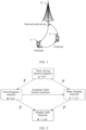
- FIG. 1 is a block diagram of a wireless communication system to which the embodiments of this application are applicable.
- the wireless communication system includes a terminal 11 and a network-side device 12.
- the terminal 11 may also be referred to as a terminal device or user equipment (User Equipment, UE), and the terminal 11 may be a terminal-side device, such as a mobile phone, a tablet computer (Tablet Personal Computer), a laptop computer (Laptop Computer) or a notebook computer, a personal digital assistant (Personal Digital Assistant, PDA), a palmtop computer, a netbook, an ultra-mobile personal computer (Ultra-Mobile Personal Computer, UMPC), a mobile Internet device (Mobile Internet Device, MID), a wearable device (Wearable Device) or vehicle user equipment (Vehicle User Equipment, VUE), or pedestrian user equipment (Pedestrian User Equipment, PUE).
- a terminal device or user equipment User Equipment
- PDA Personal Digital Assistant
- the wearable device includes: a smart watch, a wrist band, earphones, glasses, or the like. It should be noted that a specific type of the terminal 11 is not limited in the embodiments of this application.
- the network-side device 12 may be a base station or a core network device.
- the base station may be referred to as a NodeB, an evolved NodeB, an access point, a base transceiver station (Base Transceiver Station, BTS), a radio base station, a radio transceiver, a basic service set (Basic Service Set, BSS), an extended service set (Extended Service Set, ESS), a NodeB, an evolved NodeB (eNB), a home NodeB, a home evolved NodeB, a wireless local area network (Wireless Local Area Network, WLAN) access point, a wireless fidelity (Wireless Fidelity, WiFi) node, a transmission and reception point (Transmitting Receiving Point, TRP), or another appropriate term in the art.
- BTS Base Transceiver Station
- BSS Base Service Set
- ESS Extended Service Set
- a NodeB an evolved NodeB
- eNB evolved NodeB
- WLAN wireless Local Area Network
- WLAN wireless Local Area Network
- WiFi Wireless Fidelity
- TRP Transmission and reception point
- the base station is not limited to a specific technical term. It should be noted that in the embodiments of this application, the base station in the NR system is merely used as an example, and a specific type of the base station is not limited.
- the Doppler effect is caused by existence of relative velocity at the transmit end and the receive end, and signals arriving at the receiver via different paths have different angles of incidence with respect to the antenna normal, which results in differences in relative velocities and further leads to different Doppler shifts of signals from different paths.
- the original frequency of the signal is f 0
- the relative velocity at the transmit end and the receive end is ⁇ v
- the angle of incidence of the signal with respect to the antenna normal at the receive end is ⁇
- ⁇ f ⁇ v f cos ⁇ .
- the resulting Doppler shifts are also different.
- the signal observed at the receiver end is a superposition of component signals with different delays and Doppler shifts from different paths. Delay-Doppler analysis for the channel helps gather delay-Doppler information for each path, thus reflecting delay-Doppler response of the channel.
- the OTFS modulation technique logically maps information in a data packet with a size of M ⁇ N into one M ⁇ N grid point on a two-dimensional delay-Doppler domain plane, that is, pulses within each grid point modulate one symbol of the data packet. Further, one set of orthogonal two-dimensional basis functions is designed to transform a data set from the delay-Doppler domain plane of M ⁇ N to the time-frequency domain plane of N ⁇ M. Such transform is mathematically known as inverse sympletic finite Fourier transform (Inverse Sympletic Finite Fourier Transform, ISFFT).
- ISFFT Inverse Sympletic Finite Fourier Transform
- transform from the time-frequency domain to the delay-Doppler domain is known as sympletic finite Fourier transform (Sympletic Finite Fourier Transform, SFFT).
- SFFT sampletic Finite Fourier Transform
- the physical meaning behind this lies in that the signal delay-Doppler effect is actually a linear superposition effect of a series of echoes with different time and frequency offsets of a signal passing through a multipath channel.
- delay-Doppler analysis and time-frequency domain analysis can be obtained through mutual transform between the inverse sympletic finite Fourier transform and the sympletic finite Fourier transform.
- the OTFS technique transforms the time-varying multipath channel into a time-invariant (within a specific duration) two-dimensional delay-Doppler domain channel, directly reflecting the delay-Doppler response characteristics of the channel resulting from geometric characteristics of relative positions of reflectors between the transmitter and receiver in radio links.
- This eliminates difficulties in tracking time-varying fading characteristics in conventional time-frequency domain analysis; instead, all diversity characteristics of the channel in the time-frequency domain are extracted through delay-Doppler domain analysis.
- the channel impulse response matrix represented by the delay-Doppler domain features sparsity.
- the analysis of sparse channel matrices in the delay-Doppler domain using the OTFS technique allows for tighter and more flexible encapsulation of reference signals.
- OTFS modulation defines quadrature amplitude modulation (Quadrature Amplitude Modulation, QAM) symbols on the delay-Doppler plane and transforms them to the time-frequency domain for transmission. At the receive end, it is returned back to the delay-Doppler domain for processing. Therefore, a radio channel response analysis method in the delay-Doppler domain can be introduced.
- QAM Quadrature Amplitude Modulation
- a time-domain received signal is r ( t )
- a corresponding frequency-domain received signal is R ( f )
- r t F ⁇ 1 R f
- Equation (6) implies that delay-Doppler domain analysis in the OTFS system can rely on the existing communication framework established in the time-frequency domain, with additional signal processing steps performed at the transmit end and the receive end. Moreover, the additional signal processing includes only Fourier transform, which can be implemented entirely using existing hardware, without the need for additional modules. Such high compatibility with the existing hardware system greatly facilitates the application of the OTFS system. In practical systems, the OTFS technique can be conveniently implemented as pre- and post-processing modules for one filtered OFDM system, making it highly compatible with existing multi-carrier systems under the NR technology architecture.
- the implementation at the transmit end is as follows: QAM symbols containing information to be sent are carried using waveforms on the delay-Doppler plane, undergo two-dimensional ISFFT to transform into waveforms on the time-frequency domain plane of the conventional multi-carrier system, and then undergo symbol-level one-dimensional inverse fast Fourier transform (Inverse Fast Fourier Transform, IFFT) and serial-parallel conversion, and then become time-domain samples for transmission.
- QAM symbols containing information to be sent are carried using waveforms on the delay-Doppler plane, undergo two-dimensional ISFFT to transform into waveforms on the time-frequency domain plane of the conventional multi-carrier system, and then undergo symbol-level one-dimensional inverse fast Fourier transform (Inverse Fast Fourier Transform, IFFT) and serial-parallel conversion, and then become time-domain samples for transmission.
- IFFT inverse Fast Fourier Transform
- the receive end in the OTFS system roughly performs the inverse process of the transmit end: time-domain samples received by the receiver are processed through parallel-serial conversion and symbol-level one-dimensional fast Fourier transform (Fast Fourier Transform, FFT), transformed into waveforms on the time-frequency domain plane, and then undergo SFFT to transform into waveforms on the delay-Doppler domain plane.
- FFT Fast Fourier Transform
- QAM symbols carried using the delay-Doppler domain waveforms are processed by the receiver, including channel estimation and equalization, demodulation, decoding, and the like.
- OTFS modulation transforms a time-varying fading channel between the transmitter and the receiver in the time-frequency domain into a deterministic non-fading channel in the delay-Doppler domain.
- OTFS modulation transforms a time-varying fading channel between the transmitter and the receiver in the time-frequency domain into a deterministic non-fading channel in the delay-Doppler domain.
- SNR Signal-to-noise ratio
- the OTFS system analyzes a delay-Doppler image to identify reflectors in the physical channel and uses receiver equalizers to coherently combine the energy from different reflected paths, actually providing a non-fading static channel response. Utilizing this static channel characteristic, the OTFS system does not require closed-loop channel adaptation like an OFDM system to deal with rapidly changing channels, thereby improving system robustness and reducing system design complexity.
- the channel in the OTFS system can be expressed in a very compact form.
- Channel estimation in the OTFS system incurs fewer overheads and achieves higher accuracy.
- OTFS OTFS
- performance in extreme Doppler channels Through analysis of the delay-Doppler image under appropriate signal processing parameters, the Doppler characteristics of the channel can be fully presented, which facilitates signal analysis and processing in Doppler-sensitive scenarios (such as high-speed mobility and millimeter-wave).
- channel estimation in the OTFS system is performed as follows: the transmitter maps pilot pulses onto the delay-Doppler domain, and the receiver estimates the channel response h ( ⁇ , ⁇ ) of the delay-Doppler domain by analyzing the delay-Doppler image of the pilots, so as to obtain expression of channel response in the time-frequency domain according to the relationship in FIG. 2 .
- Pilot mapping onto the delay-Doppler plane can be done in a manner shown in FIG. 2 .
- a transmit signal includes a single-point pilot (301) located at ( l p , k p ), protection symbols (302) with an area of (2 l ⁇ + 1)(4 k ⁇ + 1) - 1 surrounding the single-point pilot, and a data portion of MN - (2 l ⁇ + 1)(4 k ⁇ + 1).
- two offset peaks (such as 3021 and 3022) appear in the protection band of the delay-Doppler domain grid points, indicating presence of two secondary paths with different delay Doppler in addition to the primary path.
- Amplitude, delay, and Doppler parameters of all secondary paths are measured to obtain expression of the channel in the delay-Doppler domain, that is, h ( ⁇ , ⁇ ).
- the area of the protection symbols needs to meet the following condition: l ⁇ ⁇ ⁇ max M ⁇ f , k ⁇ ⁇ ⁇ max N ⁇ T
- ⁇ max and ⁇ max are respectively the maximum delay and maximum Doppler shift of all paths in the channel, and multiple protection symbols 302 surround the single-point pilot 301 to form the protection band, with the multiple protection symbols 302 corresponding to blank resource elements.
- FIG. 4 is a flowchart of a transmission processing method according to an embodiment of this application. As shown in FIG. 4 , the method includes the following steps.
- Step 401 A transmit end splits a delay-Doppler domain resource block corresponding to each antenna in L antennas into L sub-blocks of equal size, L being an integer greater than 1.
- the transmit end may be understood as a terminal or a network-side device, and the L antennas are all or part of antennas of the transmit end.
- the transmit end may use the L antennas to implement multi-input multi-output to improve transmission performance.
- the L sub-blocks obtained by splitting the delay-Doppler domain resource blocks corresponding to different antennas have a same position in the delay-Doppler domain.
- the delay-Doppler domain resource blocks corresponding to the antennas are split in the same manner, and the L sub-blocks obtained by splitting the delay-Doppler domain resource blocks corresponding to each antenna are of a same size and position.
- Step 402 The transmit end performs delay-Doppler domain block encoding on the L antennas at the granularity of sub-block.
- the delay-Doppler domain information carried on each delay-Doppler domain resource block can be obtained and then transmitted.
- the specific process of transmission may include: first converting the delayed Doppler information to the time-frequency domain, and then mapping it to a corresponding resource for transmission.
- the transmit end splits a delay-Doppler domain resource block corresponding to each antenna in the L antennas into L sub-blocks of equal size; and the transmit end performs delay-Doppler domain block encoding at the granularity of sub-block to obtain delay-Doppler domain information carried on the delay-Doppler domain resource block.
- delay-Doppler domain coordinates within each sub-block are continuous or cyclically continuous.
- the delay-Doppler domain coordinates within the sub-block being continuous or cyclically continuous may be understood as the delay domain coordinates and Doppler domain coordinates of grid points within the sub-block being continuous or cyclically continuous.
- Cyclically continuous may include the delay domain coordinates being cyclically continuous or the Doppler domain coordinates being cyclically continuous.
- the delay domain coordinates being cyclically continuous may be understood as that one sub-block has two portions in the delay direction, the delay domain coordinates of grid points within each portion are continuous, coordinates of the delay domain grid points within one portion include the maximum delay domain coordinates and coordinates of the grid points in the other portion include the minimum delay domain coordinates.
- the Doppler domain coordinates being cyclically continuous may be understood as that one sub-block has two portions in the Doppler direction, Doppler domain coordinates of grid points within each portion are continuous, coordinates of grid points within one portion include the maximum Doppler domain coordinates, and Doppler coordinates of grid points in the other portion include the minimum delay domain coordinates.
- a direction of splitting the delay-Doppler domain resource block includes at least one of the following: a delay direction and a Doppler direction.
- splitting along one direction is illustrated as an example.
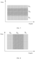
- L is equal to 2
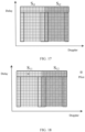
- a splitting manner is shown in FIGs. 5 to 8
- S ij in the figures denotes the j-th sub-block of the i-th antenna.
- a splitting result of a delay-Doppler domain resource block corresponding to the i-th antenna is shown in FIG. 5 .
- a splitting result of a delay-Doppler domain resource block corresponding to the i-th antenna is shown in FIG. 6 .
- a splitting result of a delay-Doppler domain resource block corresponding to the i-th antenna is shown in FIG. 7 .
- a splitting result of a delay-Doppler domain resource block corresponding to the i-th antenna is shown in FIG. 8 .
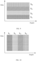
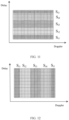
- FIGs. 9 to 12 When L is equal to 4, a splitting manner is shown in FIGs. 9 to 12 , and S ij in the figures denotes the j-th sub-block of the i-th antenna.
- S ij in the figures denotes the j-th sub-block of the i-th antenna.
- a splitting result of a delay-Doppler domain resource block corresponding to the i-th antenna is shown in FIG. 9 .
- FIG. 10 In a case of being continuously split into four sub-blocks in the Doppler direction, a splitting result of a delay-Doppler domain resource block corresponding to the i-th antenna is shown in FIG. 10 .
- a splitting result of a delay-Doppler domain resource block corresponding to the i-th antenna is shown in FIG. 11 .
- a splitting result of a delay-Doppler domain resource block corresponding to the i-th antenna is shown in FIG. 12 .
- the j-th sub-block in this embodiment of this application is not the j-th sub-block under the sorting modes given in the figures, but may alternatively be the j-th sub-block under any one of specified sorting modes.
- the j-th sub-block described above may be understood as the j-th sub-block under a specific logical sorting rule.
- that the transmit end performs delay-Doppler domain block encoding at the granularity of sub-block to obtain delay-Doppler domain information carried on the delay-Doppler domain resource block includes:
- the antenna may be understood as a physical antenna or an antenna port (for example, two or three physical antennas form one antenna port).
- the part of sub-blocks include a first sub-block and a second sub-block, and the remaining sub-blocks include a third sub-block and a fourth sub-block;
- delay-Doppler domain information S 12 carried on the 2 nd sub-block of the 1 st antenna and delay-Doppler domain information S 11 carried on the 1 st sub-block of the 1 st antenna may be configured first, and then delay-Doppler domain information S 21 carried on the 1 st sub-block of the 2 nd antenna and delay-Doppler domain information S 22 carried on the 2 nd sub-block of the 2 nd antenna are determined based on a mapping relationship for delay-Doppler domain block encoding.
- the mapping relationship may meet:
- a value of the sub-block on the left of the mapping relationship equal sign may alternatively be first determined and then a value of the sub-block on the right of the equal sign is determined based on the mapping relationship.
- the part of sub-blocks include a first sub-block, a second sub-block, a third sub-block, and a fourth sub-block
- the remaining sub-blocks include a fifth sub-block, a sixth sub-block, a seventh sub-block, and an eighth sub-block
- delay-Doppler domain information S 11 carried on the 1 st sub-block of the 1 st antenna may be configured first.
- delay-Doppler domain information S 12 carried on the 2 nd sub-block of the 1 st antenna may be configured first.
- delay-Doppler domain information S 23 carried on the 3 rd sub-block of the 2 nd antenna may be configured first.
- delay-Doppler domain information S 31 carried on the 1 st sub-block of the 3 rd antenna, delay-Doppler domain information S 32 carried on the 2 nd sub-block of the 3 rd antenna, delay-Doppler domain information S 43 carried on the 3 rd sub-block of the 4 th antenna, and delay-Doppler domain information S 44 carried on the 4 th sub-block of the 4 th antenna are determined based on a mapping relationship for delay-Doppler domain block encoding.
- the mapping relationship may meet:
- a value of the sub-block on the left of the mapping relationship equal sign may alternatively be first determined and then a value of the sub-block on the right of the equal sign is determined based on the mapping relationship.
- second delay-Doppler domain information carried on a ninth sub-block is set to be 0, the ninth sub-block being any one sub-block in the part of sub-blocks other than the first sub-block, the second sub-block, the third sub-block, and the fourth sub-block.
- a preset position of at least one of the sub-blocks is set to be a first guard period, the preset position including at least one of the following: a preset delay position and a preset Doppler position.
- the i-th antenna can be understood as the i-th antenna defined based on a logical order.
- the 1 st antenna can be understood as the 1 st antenna in an actual order or can be understood as the m-th antenna in an actual order, m being an integer greater than 1 and a value of m being determined based on a logical order.
- the first guard period meets any one of the following:
- a position of providing the first guard period can be set according to actual needs, for example, in some embodiments, the first guard period includes at least one of the following:
- a bold-line rectangular box indicates a position of providing the guard period.
- the guard period may be provided on at least one boundary in at least one direction of each sub-block. It should be understood that when guard periods are provided on one boundary in a specific direction, positions of the guard periods are located on the same-side boundary of corresponding sub-blocks (as shown in FIG. 13 , the positions of the guard periods are located on an upper-side boundary of the corresponding sub-blocks, and as shown in FIG. 15 , the positions of the guard periods are located on a left-side boundary of the corresponding sub-blocks).
- guard periods on two boundaries may be the same or different, for example, guard periods on a boundary of one side may use a cyclic prefix, and guard periods on a boundary of the other side may use a cyclic suffix.
- a width of the first guard sub-period is greater than or equal to a maximum delay of a target channel, the target channel being a channel for transmitting the delay-Doppler domain information.
- a width of the second guard sub-period is greater than or equal to twice a maximum Doppler of a target channel, the target channel being a channel for transmitting the delay-Doppler domain information.
- a pilot is configured in the first guard period.
- the pilot may be a pulse pilot or a sequence pilot.
- the pilots of all antennas are staggered using delay-Doppler domain resources, as shown in FIGs. 18 and 19 .
- the pilots of all antennas are orthogonalized based on a sequence.
- the method further includes:
- the method before the sending, by the transmit end, the time-frequency domain information, the method further includes: configuring, by the transmit end, a second guard period for the time-frequency domain information based on a preset time-domain interval.
- the configuring a second guard period for the time-frequency domain information based on a preset time-domain interval may be understood as setting one or more time domain guard periods at intervals of one time domain interval. It can be understood that the second guard period may be that the second guard period is set to be 0, or is set to be a cyclic prefix, or is set to be a cyclic suffix.
- target information is determined by the transmit end or specified by a protocol; and the target information includes at least one of the following:
- the method further includes: sending, by the transmit end, indication information to a receive end, where the indication information is used to indicate the target information.
- the indication information is carried in at least one of: radio resource control signaling, layer 1 signaling in physical downlink control channel, information in physical downlink shared channel, signaling in a media access control control element, system information block, layer 1 signaling in physical uplink control channel, information 1 in physical random access channel, information 3 in physical random access channel, information A in physical random access channel, information in physical uplink shared channel, Xn interface signaling, PC5 interface signaling, and sidelink interface signaling.
- the indication information may include a plurality of pieces of sub-indication information, and each sub-indication information is used to indicate at least one of the position information of the L sub-blocks, the rule corresponding to delay-Doppler domain block encoding, the configuration information for the guard period, pilot position, and pilot information.
- the indication information is carried in at least two of the above, each of which may include the same sub-indication information or different sub-indication information.
- the execution body may be a transmission processing apparatus, or a control module for executing the transmission processing method in the transmission processing apparatus.
- the transmission processing method being performed by the transmission processing apparatus is used as an example to describe the transmission processing apparatus provided in the embodiments of this application.
- FIG. 21 is a structural diagram of a transmission processing apparatus according to an embodiment of this application. As shown in FIG. 21 , the transmission processing apparatus 2100 includes:
- delay-Doppler domain coordinates within each sub-block are continuous or cyclically continuous.
- a direction of splitting the delay-Doppler domain resource block includes at least one of the following: a delay direction and a Doppler direction.
- the encoding module 2102 includes:
- the part of sub-blocks include a first sub-block and a second sub-block, and the remaining sub-blocks include a third sub-block and a fourth sub-block;
- the part of sub-blocks include a first sub-block, a second sub-block, a third sub-block, and a fourth sub-block
- the remaining sub-blocks include a fifth sub-block, a sixth sub-block, a seventh sub-block, and an eighth sub-block
- second delay-Doppler domain information carried on a ninth sub-block is set to be 0, the ninth sub-block being any one sub-block in the part of sub-blocks other than the first sub-block, the second sub-block, the third sub-block, and the fourth sub-block.
- a preset position of at least one of the sub-blocks is set to be a first guard period, the preset position including at least one of the following: a preset delay position and a preset Doppler position.
- the first guard period meets any one of the following:
- the first guard period includes at least one of the following:
- a width of the first guard sub-period is greater than or equal to a maximum delay of a target channel, the target channel being a channel for transmitting the delay-Doppler domain information.
- a width of the second guard sub-period is greater than or equal to twice a maximum Doppler of a target channel, the target channel being a channel for transmitting the delay-Doppler domain information.
- a pilot is configured in the first guard period.
- the transmission processing apparatus 2100 further includes:
- the transmission processing apparatus 2100 further includes: a setting module, configured to configure a second guard period for the time-frequency domain information based on a preset time-domain interval.
- the second guard period is set to be 0, or is set to be a cyclic prefix, or is set to be a cyclic suffix.
- target information is determined by the transmit end or specified by a protocol; and the target information includes at least one of the following:
- the transmission processing device 2100 further includes: a sending module, configured to send indication information to a receive end, where the indication information is used to indicate the target information.
- the indication information is carried in at least one of: radio resource control signaling, layer 1 signaling in physical downlink control channel, information in physical downlink shared channel, signaling in a media access control control element, system information block, layer 1 signaling in physical uplink control channel, information 1 in physical random access channel, information 3 in physical random access channel, information A in physical random access channel, information in physical uplink shared channel, Xn interface signaling, PC5 interface signaling, and sidelink interface signaling.
- the transmission processing apparatus provided in this embodiment of this application is capable of implementing the processes that are implemented by the method embodiments in FIG. 4 to FIG. 20 . To avoid repetition, details are not described herein again.
- the transmission processing apparatus in this embodiment of this application may be an apparatus, or an apparatus or electric device having an operating system, or may be a component, an integrated circuit, or a chip in the terminal.
- the apparatus may be a mobile terminal or a non-mobile terminal.
- the mobile terminal may include but is not limited to the types of the terminal 11 listed above, and the non-mobile terminal may be a server, a network attached storage (Network Attached Storage, NAS), a personal computer (personal computer, PC), a television (television, TV), a teller machine, a self-service machine, or the like, which is not specifically limited in this embodiment of this application.
- Network Attached Storage Network Attached Storage
- an embodiment of this application further provides a communication device 2200, including a processor 2201, a memory 2202 and a program or instructions stored in the memory 2202 and capable of running on the processor 2201.
- a communication device 2200 including a processor 2201, a memory 2202 and a program or instructions stored in the memory 2202 and capable of running on the processor 2201.
- the communication device 2200 is a terminal and when the program or instructions are executed by the processor 2201, the processes of the foregoing embodiments of the transmission processing method are implemented, with the same technical effects achieved.
- the communication device 2200 is a network-side device and when the program or instructions are executed by the processor 2201, the processes of the foregoing embodiment of the transmission processing method are implemented, with the same technical effects achieved. To avoid repetition, details are not described herein again.
- An embodiment of this application further provides a terminal, including a processor and a communication interface, where the processor is configured to split a delay-Doppler domain resource block corresponding to each antenna in L antennas of the terminal into L sub-blocks of equal size, L being an integer greater than 1; and perform delay-Doppler domain block encoding on the L antennas at the granularity of sub-block.
- the terminal embodiments correspond to the foregoing terminal-side method embodiments, and the implementation processes and implementations of the foregoing method embodiments can be applied to the terminal embodiments, with the same technical effects achieved.
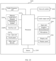
- FIG. 23 is a schematic diagram of a hardware structure of a terminal for implementing the embodiments of this application.
- the terminal 2300 includes but is not limited to at least part of components such as a radio frequency unit 2301, a network module 2302, an audio output unit 2303, an input unit 2304, a sensor 2305, a display unit 2306, a user input unit 2307, an interface unit 2308, a memory 2309, and a processor 2310.
- a radio frequency unit 2301 such as a radio frequency unit 2301, a network module 2302, an audio output unit 2303, an input unit 2304, a sensor 2305, a display unit 2306, a user input unit 2307, an interface unit 2308, a memory 2309, and a processor 2310.
- the terminal 2300 may further include a power supply (for example, a battery) supplying power to the components, and the power supply may be logically connected to the processor 2310 through a power management system. In this way, functions such as charge management, discharge management, and power consumption management are implemented by using the power management system.
- a power supply for example, a battery
- functions such as charge management, discharge management, and power consumption management are implemented by using the power management system.
- the structure of the terminal shown in FIG. 23 does not constitute any limitation on the terminal.
- the terminal may include more or fewer components than shown in the figure, or a combination of some components, or the components disposed differently. Details are not described herein again.
- the input unit 2304 may include a graphics processing unit (Graphics Processing Unit, GPU) and a microphone.
- the graphics processing unit processes image data of a still picture or video obtained by an image capture apparatus (such as a camera) in a video capture mode or an image capture mode.
- the display unit may include a display panel, and the display panel may be configured in a form of a liquid crystal display, an organic light-emitting diode, and the like.
- the user input unit may include a touch panel and other input devices.
- the touch panel is also referred to as a touchscreen.
- the touch panel may include two parts: a touch detection apparatus and a touch controller.
- the other input devices may include but are not limited to a physical keyboard, a function key (such as a volume control key or a power on/off key), a trackball, a mouse, a joystick, and the like. Details are not described herein.
- the radio frequency unit 2301 receives downlink data from a network-side device, and then sends the downlink data to the processor 2310 for processing; and also sends uplink data to the network-side device.
- the radio frequency unit 2301 includes but is not limited to an antenna, at least one amplifier, a transceiver, a coupler, a low noise amplifier, a duplexer, and the like.
- the memory 2309 may be configured to store software programs or instructions and various data.
- the memory 109 may include a program or instruction storage area and a data storage area.
- the program or instruction storage area may store an operating system, an application program or instruction required by at least one function (for example, a sound playback function or an image playback function), and the like.
- the memory 2309 may include a high-speed random access memory, and may further include a non-transitory memory.
- the non-transitory memory may be a read-only memory (Read-Only memory, ROM), a programmable read-only memory (Programmable ROM, PROM), an erasable programmable read-only memory (Erasable PROM, EPROM), an electrically erasable programmable read-only memory (Electrically EPROM, EEPROM), or a flash memory, for example, at least one disk storage device, a flash memory device, or other non-transitory solid-state storage devices.
- ROM Read-Only memory
- PROM programmable read-only memory
- Erasable PROM Erasable PROM
- EPROM electrically erasable programmable read-only memory
- EEPROM electrically erasable programmable read-only memory
- flash memory for example, at least one disk storage device, a flash memory device, or other non-transitory solid-state storage devices.
- the processor 2310 may include one or more processing units.
- an application processor and a modem processor may be integrated in the processor 2310.
- the application processor primarily processes an operating system, user interfaces, application programs or instructions, and the like.
- the modem processor primarily processes radio communication, for example, being a baseband processor. It can be understood that the modem processor may alternatively be not integrated in the processor 2310.
- the processor 2310 is configured to split a delay-Doppler domain resource block corresponding to each antenna in L antennas of the terminal into L sub-blocks of equal size, L being an integer greater than 1; and perform delay-Doppler domain block encoding on the L antennas at the granularity of sub-block.
- the delay-Doppler domain resource block corresponding to each antenna in the L antennas of the terminal into L sub-blocks of equal size; and delay-Doppler domain block encoding is performed on the L antennas at the granularity of sub-block.
- delay-Doppler domain coordinates within each sub-block are continuous or cyclically continuous.
- a direction of splitting the delay-Doppler domain resource block includes at least one of the following: a delay direction and a Doppler direction.
- the processor 2310 is specifically configured to determine first delay-Doppler domain information carried on part of sub-blocks of L*L sub-blocks; and perform mapping on the first delay-Doppler domain information based on a mapping relationship of delay-Doppler domain block encoding to obtain second delay-Doppler domain information carried on remaining sub-blocks of the L*L sub-blocks; where the L*L sub-blocks are all sub-blocks obtained through splitting delay-Doppler domain resource blocks corresponding to the L antennas.
- the part of sub-blocks include a first sub-block and a second sub-block, and the remaining sub-blocks include a third sub-block and a fourth sub-block;
- the part of sub-blocks include a first sub-block, a second sub-block, a third sub-block, and a fourth sub-block
- the remaining sub-blocks include a fifth sub-block, a sixth sub-block, a seventh sub-block, and an eighth sub-block
- second delay-Doppler domain information carried on a ninth sub-block is set to be 0, the ninth sub-block being any one sub-block in the part of sub-blocks other than the first sub-block, the second sub-block, the third sub-block, and the fourth sub-block.
- a preset position of at least one of the sub-blocks is set to be a first guard period, the preset position including at least one of the following: a preset delay position and a preset Doppler position.
- the first guard period meets any one of the following:
- the first guard period includes at least one of the following:
- a width of the first guard sub-period is greater than or equal to a maximum delay of a target channel, the target channel being a channel for transmitting the delay-Doppler domain information.
- a width of the second guard sub-period is greater than or equal to twice a maximum Doppler of a target channel, the target channel being a channel for transmitting the delay-Doppler domain information.
- a pilot is configured in the first guard period.
- the processor 2310 is further configured to transform delay-Doppler domain information obtained through delay-Doppler domain block encoding into time-frequency domain information; and the radio frequency unit 2301 is configured to send the time-frequency domain information.
- the processor 2310 is further configured to configure a second guard period for the time-frequency domain information by the transmit end based on a preset time-domain interval.
- the second guard period is set to be 0, or is set to be a cyclic prefix, or is set to be a cyclic suffix.
- target information is determined by the terminal or specified by a protocol; and the target information includes at least one of the following:
- the radio frequency unit 2301 is further configured to send indication information to a receive end, where the indication information is used to indicate the target information.
- the indication information is carried in at least one of: radio resource control signaling, layer 1 signaling in physical downlink control channel, information in physical downlink shared channel, signaling in a media access control control element, system information block, layer 1 signaling in physical uplink control channel, information 1 in physical random access channel, information 3 in physical random access channel, information A in physical random access channel, information in physical uplink shared channel, Xn interface signaling, PC5 interface signaling, and sidelink interface signaling.
- An embodiment of this application further provides a network-side device, including a processor and a communication interface, where the processor is configured to split a delay-Doppler domain resource block corresponding to each antenna in L antennas of the network-side device into L sub-blocks of equal size, L being an integer greater than 1; and perform delay-Doppler domain block encoding on the L antennas at the granularity of sub-block.
- the network-side device embodiments correspond to the foregoing network-side device method embodiments, and the implementation processes and implementations of the foregoing method embodiments can be applied to the network-side device embodiments, with the same technical effects achieved.
- the network-side device 2400 includes an antenna 2401, a radio frequency apparatus 2402, and a baseband apparatus 2403.
- the antenna 2401 is connected to the radio frequency apparatus 2402.
- the radio frequency apparatus 2402 receives information by using the antenna 2401, and sends the received information to the baseband apparatus 2403 for processing.
- the baseband apparatus 2403 processes to-be-sent information, and sends the information to the radio frequency apparatus 2402; and the radio frequency apparatus 2402 processes the received information and then sends the information out by using the antenna 2401.
- the frequency band processing apparatus may be located in the baseband apparatus 2403.
- the method performed by the network-side device in the foregoing embodiments may be implemented in the baseband apparatus 2403, and the baseband apparatus 2403 includes a processor 2404 and a memory 2405.
- the baseband apparatus 2403 may include, for example, at least one baseband board, where a plurality of chips are disposed on the baseband board. As shown in FIG. 24 , one of the chips is, for example, the processor 2404, connected to the memory 2405, to invoke a program in the memory 2405 to perform the operation of the network-side device shown in the foregoing method embodiment.
- the baseband apparatus 2403 may further include a network interface 2406, configured to exchange information with the radio frequency apparatus 2402, where the interface is, for example, a common public radio interface (common public radio interface, CPRI for short).
- a common public radio interface common public radio interface, CPRI for short.
- the network-side device in this embodiment of this application further includes: instructions or a program stored in the memory 2405 and capable of running on the processor 2404.
- the processor 2404 invokes the instructions or program in the memory 2405 to execute the method executed by the modules shown in FIG. 21 , with the same technical effects achieved. To avoid repetition, details are not described herein again.
- An embodiment of this application further provides a readable storage medium, where a program or an instruction is stored in the readable storage medium.
- a program or an instruction is stored in the readable storage medium.
- the processor is the processor in the electronic device in the foregoing embodiments.
- the readable storage medium includes a computer-readable storage medium, for example, a computer read-only memory (Read-Only Memory, ROM), a random access memory (Random Access Memory, RAM), a magnetic disk, or an optical disc.
- An embodiment of this application further provides a chip, where the chip includes a processor and a communication interface, the communication interface is coupled to the processor, and the processor is configured to run a program or instructions to implement the processes of the foregoing transmission processing method embodiments, with the same technical effects achieved. To avoid repetition, details are not repeated herein.
- the chip in the embodiments of this application may also be referred to as a system-level chip, a system chip, a chip system, a system on chip, or the like.
- An embodiment of this application further provides a computer program product, where the computer program product is stored in a non-transitory storage medium, and when being executed by at least one processor, the computer program product is configured to implement the processes of the foregoing transmission processing method embodiments, with the same technical effects achieved. To avoid repetition, details are not repeated herein.
- the computer software product is stored in a storage medium (such as a ROM/RAM, a magnetic disk, or an optical disc), and includes several instructions for instructing a terminal (which may be a mobile phone, a computer, a server, an air conditioner, a base station, or the like) to perform the methods described in the embodiments of this application.
- a storage medium such as a ROM/RAM, a magnetic disk, or an optical disc
- a terminal which may be a mobile phone, a computer, a server, an air conditioner, a base station, or the like
Landscapes
- Engineering & Computer Science (AREA)
- Signal Processing (AREA)
- Computer Networks & Wireless Communication (AREA)
- Physics & Mathematics (AREA)
- Discrete Mathematics (AREA)
- General Physics & Mathematics (AREA)
- Mobile Radio Communication Systems (AREA)
Applications Claiming Priority (2)
| Application Number | Priority Date | Filing Date | Title |
|---|---|---|---|
| CN202110739227.8A CN115549853B (zh) | 2021-06-30 | 2021-06-30 | 传输处理方法、装置、通信设备及可读存储介质 |
| PCT/CN2022/101453 WO2023274126A1 (zh) | 2021-06-30 | 2022-06-27 | 传输处理方法、装置、通信设备及可读存储介质 |
Publications (2)
| Publication Number | Publication Date |
|---|---|
| EP4366199A1 true EP4366199A1 (de) | 2024-05-08 |
| EP4366199A4 EP4366199A4 (de) | 2024-10-23 |
Family
ID=84691397
Family Applications (1)
| Application Number | Title | Priority Date | Filing Date |
|---|---|---|---|
| EP22831940.6A Pending EP4366199A4 (de) | 2021-06-30 | 2022-06-27 | Übertragungsverarbeitungsverfahren und -vorrichtung, kommunikationsvorrichtung und lesbares speichermedium |
Country Status (5)
| Country | Link |
|---|---|
| US (1) | US20240146359A1 (de) |
| EP (1) | EP4366199A4 (de) |
| JP (1) | JP7700286B2 (de) |
| CN (1) | CN115549853B (de) |
| WO (1) | WO2023274126A1 (de) |
Families Citing this family (1)
| Publication number | Priority date | Publication date | Assignee | Title |
|---|---|---|---|---|
| CN114826522B (zh) * | 2021-01-27 | 2024-06-25 | 华为技术有限公司 | 一种通信方法及装置 |
Family Cites Families (12)
| Publication number | Priority date | Publication date | Assignee | Title |
|---|---|---|---|---|
| KR101452516B1 (ko) * | 2008-08-21 | 2014-10-23 | 엘지전자 주식회사 | 다중 안테나 시스템에서 참조신호 전송 방법 |
| EP3172838A4 (de) * | 2014-07-21 | 2018-04-18 | Cohere Technologies, Inc. | Otfs-verfahren zur datenkanalcharakterisierung und verwendungen davon |
| WO2017173461A1 (en) * | 2016-04-01 | 2017-10-05 | Cohere Technologies, Inc. | Tomlinson-harashima precoding in an otfs communication system |
| WO2018021591A1 (ko) * | 2016-07-27 | 2018-02-01 | 엘지전자 주식회사 | Otfs 전송 방식을 이용하는 무선통신 시스템에서 otfs 기저 할당 방법 |
| EP3549200B1 (de) * | 2016-12-05 | 2022-06-29 | Cohere Technologies, Inc. | Fester drahtloser zugriff mittels orthogonaler zeitfrequenz-raum-modulation |
| WO2019051427A1 (en) * | 2017-09-11 | 2019-03-14 | Cohere Technologies, Inc. | WIRELESS LOCAL NETWORKS USING ORTHOGONAL TIME-FREQUENCY SPACE MODULATION |
| US11184122B2 (en) * | 2017-12-04 | 2021-11-23 | Cohere Technologies, Inc. | Implementation of orthogonal time frequency space modulation for wireless communications |
| US10715243B2 (en) * | 2018-10-19 | 2020-07-14 | Huawei Technologies Co., Ltd. | Pseudo-doppler receiving architecture for OAM and MIMO transmissions |
| WO2020095101A1 (en) * | 2018-11-06 | 2020-05-14 | Indian Institute Of Technology, Delhi | Multiple access method in wireless telecommunications system |
| CN111884975B (zh) * | 2020-07-17 | 2021-05-18 | 北京理工大学 | 基于时延-多普勒域的索引调制解调方法和系统 |
| CN112087247B (zh) * | 2020-08-04 | 2021-10-08 | 西安电子科技大学 | 一种基于大规模mimo-otfs的径分多址接入方法 |
| CN116938301A (zh) * | 2022-04-11 | 2023-10-24 | 维沃移动通信有限公司 | 信息传输方法、装置、终端及网络侧设备 |
-
2021
- 2021-06-30 CN CN202110739227.8A patent/CN115549853B/zh active Active
-
2022
- 2022-06-27 JP JP2023580829A patent/JP7700286B2/ja active Active
- 2022-06-27 WO PCT/CN2022/101453 patent/WO2023274126A1/zh not_active Ceased
- 2022-06-27 EP EP22831940.6A patent/EP4366199A4/de active Pending
-
2023
- 2023-12-28 US US18/398,946 patent/US20240146359A1/en not_active Abandoned
Also Published As
| Publication number | Publication date |
|---|---|
| JP7700286B2 (ja) | 2025-06-30 |
| US20240146359A1 (en) | 2024-05-02 |
| EP4366199A4 (de) | 2024-10-23 |
| CN115549853B (zh) | 2025-01-24 |
| JP2024525048A (ja) | 2024-07-09 |
| CN115549853A (zh) | 2022-12-30 |
| WO2023274126A1 (zh) | 2023-01-05 |
Similar Documents
| Publication | Publication Date | Title |
|---|---|---|
| CN114158090B (zh) | 数据发送方法、数据接收处理方法及相关设备 | |
| CN114142978B (zh) | 导频接收处理方法、发送方法及相关设备 | |
| WO2022171084A1 (zh) | 接入方法、装置、通信设备及可读存储介质 | |
| US20230318894A1 (en) | Pilot transmission method and apparatus, network side device, and storage medium | |
| EP4451580A1 (de) | Interferenzmessverfahren und -vorrichtung, vorrichtung und speichermedium | |
| US12231281B2 (en) | Frame structure indication method, frame structure updating method, and related device | |
| EP4387179A1 (de) | Verfahren und vorrichtung zur datenübertragungsverarbeitung, kommunikationsvorrichtung und speichermedium | |
| CN113922848A (zh) | 信号发送方法、信道估计方法、发送端设备及接收端设备 | |
| US12438750B2 (en) | Channel information processing method and apparatus | |
| US20240223319A1 (en) | Signal Transmission Method and Device | |
| WO2022183979A1 (zh) | 同步信号传输方法、装置、设备及存储介质 | |
| WO2023040956A1 (zh) | 映射方法、装置、设备及存储介质 | |
| US20240297749A1 (en) | Transmission Method, Device, and Non-Transitory Storage Medium | |
| WO2022199664A1 (zh) | 信息发送方法和设备 | |
| US20240146359A1 (en) | Transmission processing method and apparatus, communication device, and readable storage medium | |
| CN119011102A (zh) | 信号传输方法、装置、信号发送设备及信号接收设备 | |
| CN118828554A (zh) | 信号配置发送方法、接收方法、装置及通信设备 | |
| CN119865291A (zh) | 导频配置方法、装置、设备和计算机可读存储介质 |
Legal Events
| Date | Code | Title | Description |
|---|---|---|---|
| STAA | Information on the status of an ep patent application or granted ep patent |
Free format text: STATUS: THE INTERNATIONAL PUBLICATION HAS BEEN MADE |
|
| PUAI | Public reference made under article 153(3) epc to a published international application that has entered the european phase |
Free format text: ORIGINAL CODE: 0009012 |
|
| STAA | Information on the status of an ep patent application or granted ep patent |
Free format text: STATUS: REQUEST FOR EXAMINATION WAS MADE |
|
| 17P | Request for examination filed |
Effective date: 20240129 |
|
| AK | Designated contracting states |
Kind code of ref document: A1 Designated state(s): AL AT BE BG CH CY CZ DE DK EE ES FI FR GB GR HR HU IE IS IT LI LT LU LV MC MK MT NL NO PL PT RO RS SE SI SK SM TR |
|
| REG | Reference to a national code |
Ref country code: DE Ref legal event code: R079 Free format text: PREVIOUS MAIN CLASS: H04L0001000000 Ipc: H04L0001060000 |
|
| DAV | Request for validation of the european patent (deleted) | ||
| DAX | Request for extension of the european patent (deleted) | ||
| A4 | Supplementary search report drawn up and despatched |
Effective date: 20240924 |
|
| RIC1 | Information provided on ipc code assigned before grant |
Ipc: H04L 27/26 20060101ALI20240918BHEP Ipc: H04L 5/00 20060101ALI20240918BHEP Ipc: H04B 7/06 20060101ALI20240918BHEP Ipc: H04L 1/06 20060101AFI20240918BHEP |