EP4366154A1 - Procédé de fonctionnement d'un moteur synchrone à excitation permanente d'un appareil d'usinage porté à la main et appareil d'usinage porté à la main - Google Patents
Procédé de fonctionnement d'un moteur synchrone à excitation permanente d'un appareil d'usinage porté à la main et appareil d'usinage porté à la main Download PDFInfo
- Publication number
- EP4366154A1 EP4366154A1 EP22205895.0A EP22205895A EP4366154A1 EP 4366154 A1 EP4366154 A1 EP 4366154A1 EP 22205895 A EP22205895 A EP 22205895A EP 4366154 A1 EP4366154 A1 EP 4366154A1
- Authority
- EP
- European Patent Office
- Prior art keywords
- range
- variable
- synchronous motor
- rotor
- processing device
- Prior art date
- Legal status (The legal status is an assumption and is not a legal conclusion. Google has not performed a legal analysis and makes no representation as to the accuracy of the status listed.)
- Granted
Links
Images

Classifications
-
- H—ELECTRICITY
- H02—GENERATION; CONVERSION OR DISTRIBUTION OF ELECTRIC POWER
- H02P—CONTROL OR REGULATION OF ELECTRIC MOTORS, ELECTRIC GENERATORS OR DYNAMO-ELECTRIC CONVERTERS; CONTROLLING TRANSFORMERS, REACTORS OR CHOKE COILS
- H02P6/00—Arrangements for controlling synchronous motors or other dynamo-electric motors using electronic commutation dependent on the rotor position; Electronic commutators therefor
- H02P6/20—Arrangements for starting
- H02P6/22—Arrangements for starting in a selected direction of rotation
-
- H—ELECTRICITY
- H02—GENERATION; CONVERSION OR DISTRIBUTION OF ELECTRIC POWER
- H02P—CONTROL OR REGULATION OF ELECTRIC MOTORS, ELECTRIC GENERATORS OR DYNAMO-ELECTRIC CONVERTERS; CONTROLLING TRANSFORMERS, REACTORS OR CHOKE COILS
- H02P6/00—Arrangements for controlling synchronous motors or other dynamo-electric motors using electronic commutation dependent on the rotor position; Electronic commutators therefor
- H02P6/14—Electronic commutators
- H02P6/16—Circuit arrangements for detecting position
- H02P6/18—Circuit arrangements for detecting position without separate position detecting elements
- H02P6/185—Circuit arrangements for detecting position without separate position detecting elements using inductance sensing, e.g. pulse excitation
-
- A—HUMAN NECESSITIES
- A01—AGRICULTURE; FORESTRY; ANIMAL HUSBANDRY; HUNTING; TRAPPING; FISHING
- A01D—HARVESTING; MOWING
- A01D34/00—Mowers; Mowing apparatus of harvesters
- A01D34/01—Mowers; Mowing apparatus of harvesters characterised by features relating to the type of cutting apparatus
- A01D34/02—Mowers; Mowing apparatus of harvesters characterised by features relating to the type of cutting apparatus having reciprocating cutters
- A01D34/30—Driving mechanisms for the cutters
- A01D34/37—Driving mechanisms for the cutters electric
-
- A—HUMAN NECESSITIES
- A01—AGRICULTURE; FORESTRY; ANIMAL HUSBANDRY; HUNTING; TRAPPING; FISHING
- A01D—HARVESTING; MOWING
- A01D34/00—Mowers; Mowing apparatus of harvesters
- A01D34/835—Mowers; Mowing apparatus of harvesters specially adapted for particular purposes
- A01D34/90—Mowers; Mowing apparatus of harvesters specially adapted for particular purposes for carrying by the operator
-
- A—HUMAN NECESSITIES
- A01—AGRICULTURE; FORESTRY; ANIMAL HUSBANDRY; HUNTING; TRAPPING; FISHING
- A01D—HARVESTING; MOWING
- A01D46/00—Picking of fruits, vegetables, hops, or the like; Devices for shaking trees or shrubs
- A01D46/26—Devices for shaking trees or shrubs; Fruit catching devices to be used therewith
- A01D46/264—Devices for beating or vibrating the foliage; Fruit catching devices to be used therewith
-
- B—PERFORMING OPERATIONS; TRANSPORTING
- B25—HAND TOOLS; PORTABLE POWER-DRIVEN TOOLS; MANIPULATORS
- B25F—COMBINATION OR MULTI-PURPOSE TOOLS NOT OTHERWISE PROVIDED FOR; DETAILS OR COMPONENTS OF PORTABLE POWER-DRIVEN TOOLS NOT PARTICULARLY RELATED TO THE OPERATIONS PERFORMED AND NOT OTHERWISE PROVIDED FOR
- B25F5/00—Details or components of portable power-driven tools not particularly related to the operations performed and not otherwise provided for
-
- H—ELECTRICITY
- H02—GENERATION; CONVERSION OR DISTRIBUTION OF ELECTRIC POWER
- H02K—DYNAMO-ELECTRIC MACHINES
- H02K7/00—Arrangements for handling mechanical energy structurally associated with dynamo-electric machines, e.g. structural association with mechanical driving motors or auxiliary dynamo-electric machines
- H02K7/14—Structural association with mechanical loads, e.g. with hand-held machine tools or fans
- H02K7/145—Hand-held machine tool
-
- H—ELECTRICITY
- H02—GENERATION; CONVERSION OR DISTRIBUTION OF ELECTRIC POWER
- H02P—CONTROL OR REGULATION OF ELECTRIC MOTORS, ELECTRIC GENERATORS OR DYNAMO-ELECTRIC CONVERTERS; CONTROLLING TRANSFORMERS, REACTORS OR CHOKE COILS
- H02P6/00—Arrangements for controlling synchronous motors or other dynamo-electric motors using electronic commutation dependent on the rotor position; Electronic commutators therefor
- H02P6/08—Arrangements for controlling the speed or torque of a single motor
-
- H—ELECTRICITY
- H02—GENERATION; CONVERSION OR DISTRIBUTION OF ELECTRIC POWER
- H02P—CONTROL OR REGULATION OF ELECTRIC MOTORS, ELECTRIC GENERATORS OR DYNAMO-ELECTRIC CONVERTERS; CONTROLLING TRANSFORMERS, REACTORS OR CHOKE COILS
- H02P6/00—Arrangements for controlling synchronous motors or other dynamo-electric motors using electronic commutation dependent on the rotor position; Electronic commutators therefor
- H02P6/20—Arrangements for starting
-
- H—ELECTRICITY
- H02—GENERATION; CONVERSION OR DISTRIBUTION OF ELECTRIC POWER
- H02P—CONTROL OR REGULATION OF ELECTRIC MOTORS, ELECTRIC GENERATORS OR DYNAMO-ELECTRIC CONVERTERS; CONTROLLING TRANSFORMERS, REACTORS OR CHOKE COILS
- H02P6/00—Arrangements for controlling synchronous motors or other dynamo-electric motors using electronic commutation dependent on the rotor position; Electronic commutators therefor
- H02P6/30—Arrangements for controlling the direction of rotation
-
- A—HUMAN NECESSITIES
- A01—AGRICULTURE; FORESTRY; ANIMAL HUSBANDRY; HUNTING; TRAPPING; FISHING
- A01D—HARVESTING; MOWING
- A01D46/00—Picking of fruits, vegetables, hops, or the like; Devices for shaking trees or shrubs
- A01D46/26—Devices for shaking trees or shrubs; Fruit catching devices to be used therewith
- A01D2046/266—Portable devices to shake branches
-
- A—HUMAN NECESSITIES
- A01—AGRICULTURE; FORESTRY; ANIMAL HUSBANDRY; HUNTING; TRAPPING; FISHING
- A01D—HARVESTING; MOWING
- A01D34/00—Mowers; Mowing apparatus of harvesters
- A01D34/01—Mowers; Mowing apparatus of harvesters characterised by features relating to the type of cutting apparatus
- A01D34/412—Mowers; Mowing apparatus of harvesters characterised by features relating to the type of cutting apparatus having rotating cutters
- A01D34/63—Mowers; Mowing apparatus of harvesters characterised by features relating to the type of cutting apparatus having rotating cutters having cutters rotating about a vertical axis
- A01D34/76—Driving mechanisms for the cutters
- A01D34/78—Driving mechanisms for the cutters electric
-
- H—ELECTRICITY
- H02—GENERATION; CONVERSION OR DISTRIBUTION OF ELECTRIC POWER
- H02P—CONTROL OR REGULATION OF ELECTRIC MOTORS, ELECTRIC GENERATORS OR DYNAMO-ELECTRIC CONVERTERS; CONTROLLING TRANSFORMERS, REACTORS OR CHOKE COILS
- H02P2203/00—Indexing scheme relating to controlling arrangements characterised by the means for detecting the position of the rotor
- H02P2203/03—Determination of the rotor position, e.g. initial rotor position, during standstill or low speed operation
Definitions
- the invention relates to a method for operating a permanent magnet synchronous motor of a hand-held machining device and to a hand-held machining device.
- the invention is based on the object of providing a method for operating a permanent magnet synchronous motor of a hand-held processing device and a hand-held processing device, each of which has improved properties.
- the invention solves this problem by providing a method and a hand-held processing device described in the independent claims.
- Advantageous developments and/or embodiments of the invention are described in the dependent claims.
- the method according to the invention is for operating a permanently excited synchronous motor of a hand-held processing device.
- the method has the steps: a) sensorless determination of a position variable representative of a position of a rotor of the synchronous motor at a standstill, in particular of the rotor. b) determining a directional variable for a continuous rotation of the rotor from a standstill in one direction depending on the determined position variable such that an amount of an achievable torque that can be generated by the synchronous motor when it is controlled, in particular sensorless, to rotate in the direction is greater than an amount of a breakaway torque limit of the processing device. c), in particular sensorless, controlling the synchronous motor to rotate in the direction depending on the determined directional variable.
- this enables, in particular the determination of the direction variable, a particularly reliable starting or starting or cranking of the synchronous motor, in particular from any possible position of the rotor.
- the method, operation, detection and/or control may be automatic.
- BLDC brushless DC motor
- BL motor BL motor
- EC motor electronically commutated motor
- permanent magnet synchronous motor can be used synonymously with the term “permanently excited synchronous motor”.
- the synchronous motor can be three-phase and/or have a stator, in particular a three-phase one.
- the synchronous motor can or does not need to have a magnetic sensor, such as a Hall sensor, in particular for detecting and controlling.
- a magnetic sensor such as a Hall sensor
- the processing device can have a tool, wherein the synchronous motor can be designed to drive the tool. Additionally or alternatively, the processing device can be electric, in particular a battery-powered device. Furthermore, additionally or alternatively, the processing device can be a gardening, forestry, construction or soil processing device.
- Hand-held processing device can mean that the processing device can have a mass of maximum 50 kg (kilograms), in particular maximum 20 kg, in particular maximum 10 kg, in particular maximum 5 kg, and/or minimum 0.2 kg, in particular minimum 0.5 kg, in particular minimum 1 kg, in particular minimum 2 kg.
- the processing device can have a user-operable control element, wherein step c), in particular the method, can be triggered or carried out depending on an actuation of the control element.
- encoder can be used synonymously for the term “sensor”.
- the position size can be initial and/or current and/or physical.
- the position size, position, direction size and/or direction may have a value.
- the position can be absolute and/or a rotational position.
- angular position or “location” can be used synonymously for the term “position”.
- the directional quantity can be physical.
- the directional magnitude and/or the direction may be, in particular at a time and/or either, a clockwise or a counterclockwise direction.
- Continuous rotation can mean permanent and/or uninterrupted rotation and/or without a standstill and/or by at least 180 ° (degrees), in particular at least 360 °, and/or to reach a target speed, in particular at least 10 % (percent) of a nominal speed, of the rotor.
- the direction can be a rotational direction.
- starting torque or “starting torque” can be used synonymously for the term “torque”.
- the breakaway torque limit can be set or specified as a function of a, in particular minimum, required breakaway torque, in particular in a proper and/or freely moving or load-free, in particular non-blocked or non-jammed, state of the processing device, and/or, in particular by the factory or manufacturer and/or fixed, in particular equal to or greater than the breakaway torque, and/or not be specifiable by a user.
- the achievable torque can depend on the position, which can be fixed or not determinable, and the direction, which can be determined, in particular is determined. Additionally or alternatively, the amount of torque for turning in, in particular, at least one of two possible directions can always be achievable, since the processing device, in particular the synchronous motor, can be designed or constructed in this way.
- the rotation can be determined either in a first direction, and in particular not in a second direction, or in the second direction, and in particular not in the first direction, or in the first direction or in the second direction, wherein the second direction can be opposite to the first direction.
- the magnitude of the torque may, but need not, be determined and/or whether the magnitude of the torque for turning in the direction is greater than the magnitude of the breakaway torque limit.
- step c the synchronous motor can be controlled in the same way as in step b).
- Step b) can be carried out after step a). Additionally or alternatively, step c) can be carried out after step b).
- the control can be by generating control voltages for the, in particular three, phases of the synchronous motor and/or comprise commutation, in particular be commutation.
- step b) comprises: determining the direction variable for rotation in the first direction, and in particular not in the second direction, if the determined position variable is representative of a first position range of possible positions of the rotor in, in particular at least, a first position variable range.
- the amount of torque for rotation in the first direction is greater and in the second direction it is equal to or less than the amount of the breakaway torque limit.
- the second direction is opposite to the first direction.
- step b) comprises: determining the direction variable for rotation in the second direction, and in particular not in the first direction, if the determined position variable is representative of a second position range of possible positions of the rotor in, in particular at least, a second position variable range.
- the second position variable range is different from, in particular completely different from, the first position variable range. In the second position range, the amount of torque for rotation in the second direction is greater and in the first direction it is equal to or less than the amount of the breakaway torque limit.
- step b) comprises: determining the direction variable for rotation, in particular either in the first direction or in the second direction, if the determined position variable is representative of a third position range of possible positions of the rotor in, in particular at least, a third position variable range.
- the third position size range is different, in particular completely, from the first position size range and in particular the second position size range. In the third position range, the amount of torque for turning in the first direction and in the second direction is greater than the amount of the breakaway torque limit.
- step b) it can be determined whether the position size is in the second position size range or not, and/or is in the third position size range or not.
- the first position range and/or the second position range and/or the third position range extend, in particular each, over a minimum of 1°, in particular a minimum of 2°, in particular a minimum of 5°, and/or a maximum of 180°, in particular a maximum of 120°, in particular a maximum of 60°.
- the first position range is one of several first position ranges and/or the second position range is one of several second position ranges and/or the third position range is one of several third position ranges.
- the first position size range is one of several first position size ranges and/or the second position size range is one of several second position size ranges and/or the third position size range is one of several third position size ranges.
- the first position ranges/position size ranges, the second position ranges/position size ranges and/or the third position ranges/position size ranges can alternate.
- step b) comprises: determining the direction variable for the rotation in the first direction or in the second direction, the second direction being opposite to the first direction, such that when the method is carried out multiple times or repeatedly, the rotation in the first direction and in the second direction is evenly distributed, in particular if the determined position variable is in the third position variable range.
- step b) comprises: determining the direction variable for the rotation in the first direction or in the second direction, the second direction being opposite to the first direction, such that when the method is carried out multiple times or repeatedly, the rotation in the first direction and in the second direction is evenly distributed, in particular if the determined position variable is in the third position variable range.
- the processing device can be operated without a preferred direction of the rotor or without a preferred direction, in particular.
- the term “preference” can be used synonymously for the term “preference”.
- the processing device is a special harvester, in particular an olive shaker or a hedge trimmer.
- the processing device has a non-rotating, in particular oscillating translational, tool, in particular at least one rake.
- the tool can be designed to move in two, in particular opposite, directions of movement. In other words: the tool can be designed to reverse the direction of movement or to move back and forth. Additionally or alternatively, the movement can describe the shape of an open or non-closed curve.
- the term "reciprocal” or "straight” or "oscillating" can be used synonymously for the term "translatory".
- the processing device has a conversion device, in particular a gear.
- the conversion device is designed to convert the rotation of the rotor into a non-rotating movement, in particular an oscillating translational movement. This allows the processing device to be without a preferred direction of the rotor and/or to be the special harvester or the hedge trimmer and/or to have the non-rotating tool. Additionally or alternatively, the evenly distributed rotation enables even wear of the conversion device.
- the gear can be mechanical and/or a coupling gear, in particular a crank drive. Additionally or alternatively, the conversion can be automatic.
- step a), in particular the method up to step c), is carried out without rotating the rotor.
- step b) is carried out after step a) without an intermediate step and/or immediately.
- step c) is carried out after step b) without an intermediate step and/or immediately and/or without the rotor coming to a standstill.
- the determination comprises measuring at least one inductance, in particular inductances, of the synchronous motor, in particular of the stator, using test signals, in particular an indirect flux determination by online reactance measurement (INFORM), a high-frequency square wave injection, or an injection of a rotating or alternating test signal in a rotor or stator-oriented coordinate system.
- test signals in particular an indirect flux determination by online reactance measurement (INFORM), a high-frequency square wave injection, or an injection of a rotating or alternating test signal in a rotor or stator-oriented coordinate system.
- IFORM online reactance measurement
- the test signals can be high-frequency and/or voltage test signals. In other words: the test signals can be chosen to be so short in terms of their strength and duration that they cannot cause the rotor to rotate.
- test signals in particular three
- the test signals can be rectangular or sinusoidal test voltages, in particular those that can be applied to associated phases of the three-phase synchronous motor.
- the synchronous motor can have at least one voltage and/or current sensor for measuring, in particular, voltages and/or currents in the phases.
- the position size is the position, in particular determined by means of calculation. Additionally or alternatively, the direction size is the direction, in particular determined. In particular, the position size range can be the position range.
- the amount of torque that can be generated by the synchronous motor when it is controlled without sensors can be achieved with a maximum permissible current amplitude of the synchronous motor.
- the current amplitude can have a value.
- nominal current can be used synonymously for the term "maximum permissible current amplitude”.
- the hand-held processing device has the permanent magnet synchronous motor and a control device.
- the control device is designed to carry out a method, in particular the method as described above.
- the processing device can enable the same advantage(s) as described above for the method.
- the processing device can be designed as described above for the method.
- the control device can be electrical and/or in the form of a microprocessor control. Further additionally or alternatively, the execution can be automatic.
- Fig. 1 to 4 show a method according to the invention for operating a permanently excited synchronous motor 2 of a hand-held processing device 1 and the hand-held processing device 1 according to the invention comprising the permanently excited synchronous motor 2 and a control device 3.
- the control device 3 is designed to carry out the method, in particular carries out.
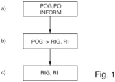
- the method comprises the steps: a) sensorless determination of a position variable POG representative of a position PO of a rotor 4 of the synchronous motor 2 at a standstill, by means of the control device 3. b) determination of a direction variable RIG for a continuous rotation of the rotor 4 from the standstill in a direction RI depending on the determined position variable POG such that an amount BDM of an achievable torque DM that can be generated by the synchronous motor 2 when it is controlled sensorlessly to rotate in the direction RI is greater than an amount BLM of a breakaway torque limit LM of the processing device 1 is as in Fig.2 shown, by means of the control device 3. c) sensorless control of the synchronous motor 2 depending on the determined direction variable RIG to rotate in the direction RI, by means of the control device 3.
- step b) comprises: determining the direction variable RIG for rotation in a first direction RI1 if the determined position variable POG in a first position variable range POGB1 is representative of a first position range POB1 of possible positions of the rotor 4.
- the amount BDM of the torque DM for rotation in the first direction RI1 is greater and in a second direction RI2 it is equal to or less than the amount BLM of the breakaway torque limit LM.
- the second direction RI2 is opposite to the first direction RI1.
- step b) comprises: determining the direction variable RIG for rotation in the second direction RI2 if the determined position variable POG in a second position variable range POGB2 is representative of a second position variable range POB2 of possible positions of the rotor 4.
- the second position variable range POGB2 is different from the first position variable range POGB1.
- the amount BDM of the torque DM for rotation in the second direction RI2 is greater and in the first direction RI1 it is equal to or less than the amount BLM of the breakaway torque limit LM.
- step b) comprises: determining the direction variable RIG for rotation in the first direction RI1 or in the second direction RI2 if the determined position variable POG in a third position variable range POGB3 is representative of a third position variable range POB3 of possible positions of the rotor 4.
- the third position variable range POGB3 is different from the first position variable range POGB1, and in particular the second position variable range POGB2.
- the amount BDM of the torque DM for rotation in the first direction RI1 and in the second direction RI2 is greater than the amount BLM of the breakaway torque limit LM.
- first position range POB1 and/or the second position range POB2 and/or the third position range POB3 extend over a minimum of 1°, in particular a minimum of 2°, in particular a minimum of 5°, and/or a maximum of 180°, in particular a maximum of 120°, in particular a maximum of 60°.
- the first position range POB1 is one of a plurality of first position ranges POB1, in the embodiment shown four, and/or the second position range POB2 is one of a plurality of second position ranges POB2, in the embodiment shown two, and/or the third position range POB3 is one of a plurality of third position ranges POB3, in the embodiment shown five.
- first position size range POGB1 is one of a plurality of first position size ranges POGB1, in the embodiment shown the four, and/or the second position size range POGB2 is one of a plurality of second position size ranges POGB2, in the embodiment shown the two, and/or the third position size range POGB3 is one of a plurality of third position size ranges POGB3, in the embodiment shown the five.
- step b) comprises: determining the direction variable RIG for the rotation in the first direction RI1 or in the second direction RI2, wherein the second direction RI2 is opposite to the first direction RI1, such that when the method is carried out multiple times, the rotation in the first direction RI1 and in the second direction RI2 is evenly distributed, in particular if the determined position variable POG is in the third position variable range POGB3.
- processing device 1 can be operated without a preferred direction of the rotor 4.
- processing device 1 is a special harvester 1', in particular an olive shaker 1", as in Fig. 3 shown, or a hedge trimmer 1′′′, as in Fig.4 shown.
- the processing device 1 has a non-rotating, in particular oscillating translational, tool 5, in particular at least one rake 5', as in Fig. 3 shown.
- the processing device 1 has a conversion device 6, in particular a gear 6'.
- the conversion device 6 is designed to convert, in particular converts, the rotation of the rotor 4 into a non-rotating movement, in particular an oscillating translational movement, in particular of the tool 5.
- step a), in particular the method up to step c), is carried out without rotation of the rotor 4.
- step b) is carried out after step a) without an intermediate step and/or immediately.
- step c) is carried out after step b) without an intermediate step and/or immediately and/or without the rotor 4 coming to a standstill.
- the determination comprises measuring at least one inductance of synchronous motor 2 by means of test signals, in particular an indirect flux determination by online reactance measurement (INFORM), a high-frequency square wave injection, or an injection of a rotating or alternating test signal in a rotor- or stator-oriented coordinate system.
- IFORM online reactance measurement
- a high-frequency square wave injection or an injection of a rotating or alternating test signal in a rotor- or stator-oriented coordinate system.
- the position variable POG is the position PO, in particular determined by means of calculation.
- the direction variable RIG is the direction RI, in particular determined.
- the amount BDM of the torque DM that can be generated by the synchronous motor 2 when it is controlled without sensors can be achieved with a maximum permissible current amplitude IA of the synchronous motor 2.
- the invention provides an advantageous method for operating a permanently excited synchronous motor of a hand-held processing device and an advantageous hand-held processing device, each of which has improved properties.
Landscapes
- Engineering & Computer Science (AREA)
- Power Engineering (AREA)
- Life Sciences & Earth Sciences (AREA)
- Environmental Sciences (AREA)
- Mechanical Engineering (AREA)
- Control Of Ac Motors In General (AREA)
- Control Of Motors That Do Not Use Commutators (AREA)
Priority Applications (3)
| Application Number | Priority Date | Filing Date | Title |
|---|---|---|---|
| EP22205895.0A EP4366154B1 (fr) | 2022-11-07 | 2022-11-07 | Procédé de fonctionnement d'un moteur synchrone à excitation permanente d'un appareil d'usinage porté à la main et appareil d'usinage porté à la main |
| US18/502,436 US12567819B2 (en) | 2022-11-07 | 2023-11-06 | Method for operating a permanently excited synchronous motor of a hand-held working device, and hand-held working device |
| CN202311476489.5A CN117997174A (zh) | 2022-11-07 | 2023-11-07 | 运行手持加工设备的永磁激励同步电机的方法和手持加工设备 |
Applications Claiming Priority (1)
| Application Number | Priority Date | Filing Date | Title |
|---|---|---|---|
| EP22205895.0A EP4366154B1 (fr) | 2022-11-07 | 2022-11-07 | Procédé de fonctionnement d'un moteur synchrone à excitation permanente d'un appareil d'usinage porté à la main et appareil d'usinage porté à la main |
Publications (2)
| Publication Number | Publication Date |
|---|---|
| EP4366154A1 true EP4366154A1 (fr) | 2024-05-08 |
| EP4366154B1 EP4366154B1 (fr) | 2026-04-29 |
Family
ID=84330191
Family Applications (1)
| Application Number | Title | Priority Date | Filing Date |
|---|---|---|---|
| EP22205895.0A Active EP4366154B1 (fr) | 2022-11-07 | 2022-11-07 | Procédé de fonctionnement d'un moteur synchrone à excitation permanente d'un appareil d'usinage porté à la main et appareil d'usinage porté à la main |
Country Status (3)
| Country | Link |
|---|---|
| US (1) | US12567819B2 (fr) |
| EP (1) | EP4366154B1 (fr) |
| CN (1) | CN117997174A (fr) |
Citations (3)
| Publication number | Priority date | Publication date | Assignee | Title |
|---|---|---|---|---|
| US5432414A (en) * | 1992-03-30 | 1995-07-11 | Kabushiki Kaisha Toshiba | Sensorless spindle motor control apparatus |
| DE102014226285A1 (de) * | 2013-12-20 | 2015-06-25 | Semiconductor Components Industries, Llc | Motorsteuerschaltung und Verfahren |
| US20200343838A1 (en) * | 2019-04-25 | 2020-10-29 | Black & Decker Inc. | Dual-controller system for a sensorless brushless motor control |
Family Cites Families (8)
| Publication number | Priority date | Publication date | Assignee | Title |
|---|---|---|---|---|
| US5191270A (en) | 1991-06-07 | 1993-03-02 | Sgs-Thomson Microelectronics, Inc. | Method for starting a motor |
| US5327053A (en) | 1992-08-12 | 1994-07-05 | Seagate Technology, Inc. | Apparatus and method for detecting rotor position in a sensorless and brushless DC motor |
| KR20090084044A (ko) | 2008-01-31 | 2009-08-05 | 엘지전자 주식회사 | 모터의 기동방법 |
| KR101982281B1 (ko) * | 2012-07-31 | 2019-05-27 | 삼성전자주식회사 | 영구자석 동기 전동기에서 생성 가능한 최대 자속을 획득하는 방법 및 장치. |
| US9479090B2 (en) | 2013-12-20 | 2016-10-25 | Semiconductor Components Industries, Llc | Motor control circuit and method |
| FR3044185B1 (fr) * | 2015-11-23 | 2018-11-16 | Safran Electrical & Power | Procede de commande d'une machine synchrone a aimants permanents, et dispositif correspondant |
| FR3062762B1 (fr) * | 2017-02-08 | 2020-08-07 | Valeo Siemens Eautomotive France Sas | Procede d'estimation de la position angulaire d’un rotor d’un systeme d’entrainement electrique |
| EP3667894B1 (fr) * | 2018-12-12 | 2022-03-23 | Siemens Gamesa Renewable Energy A/S | Procédé pour déterminer la position de rotation d'un rotor dans un moteur synchrone à aimant permanent |
-
2022
- 2022-11-07 EP EP22205895.0A patent/EP4366154B1/fr active Active
-
2023
- 2023-11-06 US US18/502,436 patent/US12567819B2/en active Active
- 2023-11-07 CN CN202311476489.5A patent/CN117997174A/zh active Pending
Patent Citations (3)
| Publication number | Priority date | Publication date | Assignee | Title |
|---|---|---|---|---|
| US5432414A (en) * | 1992-03-30 | 1995-07-11 | Kabushiki Kaisha Toshiba | Sensorless spindle motor control apparatus |
| DE102014226285A1 (de) * | 2013-12-20 | 2015-06-25 | Semiconductor Components Industries, Llc | Motorsteuerschaltung und Verfahren |
| US20200343838A1 (en) * | 2019-04-25 | 2020-10-29 | Black & Decker Inc. | Dual-controller system for a sensorless brushless motor control |
Also Published As
| Publication number | Publication date |
|---|---|
| US12567819B2 (en) | 2026-03-03 |
| US20240154551A1 (en) | 2024-05-09 |
| CN117997174A (zh) | 2024-05-07 |
| EP4366154B1 (fr) | 2026-04-29 |
Similar Documents
| Publication | Publication Date | Title |
|---|---|---|
| DE102004052652B4 (de) | Motorantriebssystem | |
| EP1279218B1 (fr) | Procede de contrôle d'un moteur a reluctance | |
| DE102004038414A1 (de) | Chirurgische Maschine und Verfahren zum Betreiben einer chirurgischen Maschine | |
| DE102012102868A1 (de) | Verfahren zum Betreiben eines bürstenlosen Elektromotors | |
| DE112016004132B4 (de) | Steuervorrichtung eines elektrischen Synchronmotors, integriertes Motorsystem, Pumpensystem und Positioniersystem | |
| EP4366154A1 (fr) | Procédé de fonctionnement d'un moteur synchrone à excitation permanente d'un appareil d'usinage porté à la main et appareil d'usinage porté à la main | |
| DE202014106242U1 (de) | Bürstenloser Motor | |
| EP1734648B1 (fr) | Excitation asymétrique d'un moteur électrique sans capteur et sans balai | |
| EP1501185B1 (fr) | Méthode et dispositif pour positionner un dispositif rotatif | |
| DE102013014480A1 (de) | Verfahren zum Betreiben eines Elektromotors | |
| WO2018024280A1 (fr) | Unité de commande et procédé de commande d'une machine électrique | |
| WO2020114816A1 (fr) | Procédé de synchronisation sur le réseau d'une machine à courant triphasé à excitation permanente avec un démarreur progressif comprenant des thyristors | |
| EP3320613A1 (fr) | Fonctionnement d'une machine tournante électrique comprenant deux capteurs de position | |
| AT502615B1 (de) | Verfahren zur direkten regelung der reaktanz einer drehstrommaschine | |
| WO2014161614A1 (fr) | Procédé de mise en marche d'un moteur électrique à vitesse variable | |
| EP3319222B1 (fr) | Procédé de commande pour un moteur électrique, appareil de commande ainsi que moteur électrique | |
| DE102020106106A1 (de) | Elektromotor sowie Ansteuerungsverfahren | |
| DE10300634A1 (de) | Verfahren zur Steuerung eines elektronisch kommutierten Gleichstrommotors | |
| DE102006032092A1 (de) | Verfahren und Einrichtung zum Betrieb eines Synchronmotors | |
| EP4287496A1 (fr) | Commutation de blocs sans capteur | |
| WO1998011661A1 (fr) | Procede de commande pour moteurs electriques sans balais | |
| DE102020134580A1 (de) | Verfahren zum Erkennen eines Fehlerzustands bei einem elektronisch kommutierten Gleichstrommotor | |
| EP4465518A1 (fr) | Procédé de commande d'un moteur électrique et dispositif de commande électronique | |
| EP4601183A1 (fr) | Procédé et dispositif de commande indirecte orientée champ d'un moteur à courant continu sans balai | |
| WO2009118299A2 (fr) | Ensemble circuit destiné au fonctionnement sans capteur d'un moteur universel d'appareil électroménager et procédé associé |
Legal Events
| Date | Code | Title | Description |
|---|---|---|---|
| PUAI | Public reference made under article 153(3) epc to a published international application that has entered the european phase |
Free format text: ORIGINAL CODE: 0009012 |
|
| STAA | Information on the status of an ep patent application or granted ep patent |
Free format text: STATUS: THE APPLICATION HAS BEEN PUBLISHED |
|
| AK | Designated contracting states |
Kind code of ref document: A1 Designated state(s): AL AT BE BG CH CY CZ DE DK EE ES FI FR GB GR HR HU IE IS IT LI LT LU LV MC ME MK MT NL NO PL PT RO RS SE SI SK SM TR |
|
| STAA | Information on the status of an ep patent application or granted ep patent |
Free format text: STATUS: REQUEST FOR EXAMINATION WAS MADE |
|
| 17P | Request for examination filed |
Effective date: 20241015 |
|
| RBV | Designated contracting states (corrected) |
Designated state(s): AL AT BE BG CH CY CZ DE DK EE ES FI FR GB GR HR HU IE IS IT LI LT LU LV MC ME MK MT NL NO PL PT RO RS SE SI SK SM TR |
|
| GRAP | Despatch of communication of intention to grant a patent |
Free format text: ORIGINAL CODE: EPIDOSNIGR1 |
|
| STAA | Information on the status of an ep patent application or granted ep patent |
Free format text: STATUS: GRANT OF PATENT IS INTENDED |
|
| INTG | Intention to grant announced |
Effective date: 20251201 |
|
| GRAS | Grant fee paid |
Free format text: ORIGINAL CODE: EPIDOSNIGR3 |
|
| GRAA | (expected) grant |
Free format text: ORIGINAL CODE: 0009210 |
|
| STAA | Information on the status of an ep patent application or granted ep patent |
Free format text: STATUS: THE PATENT HAS BEEN GRANTED |