EP4365505A1 - Air conditioning system - Google Patents
Air conditioning system Download PDFInfo
- Publication number
- EP4365505A1 EP4365505A1 EP22832693.0A EP22832693A EP4365505A1 EP 4365505 A1 EP4365505 A1 EP 4365505A1 EP 22832693 A EP22832693 A EP 22832693A EP 4365505 A1 EP4365505 A1 EP 4365505A1
- Authority
- EP
- European Patent Office
- Prior art keywords
- air
- refrigerant
- unit
- heat exchanger
- pipe
- Prior art date
- Legal status (The legal status is an assumption and is not a legal conclusion. Google has not performed a legal analysis and makes no representation as to the accuracy of the status listed.)
- Pending
Links
Images






Classifications
-
- F—MECHANICAL ENGINEERING; LIGHTING; HEATING; WEAPONS; BLASTING
- F24—HEATING; RANGES; VENTILATING
- F24F—AIR-CONDITIONING; AIR-HUMIDIFICATION; VENTILATION; USE OF AIR CURRENTS FOR SCREENING
- F24F11/00—Control or safety arrangements
- F24F11/70—Control systems characterised by their outputs; Constructional details thereof
- F24F11/80—Control systems characterised by their outputs; Constructional details thereof for controlling the temperature of the supplied air
- F24F11/83—Control systems characterised by their outputs; Constructional details thereof for controlling the temperature of the supplied air by controlling the supply of heat-exchange fluids to heat-exchangers
- F24F11/84—Control systems characterised by their outputs; Constructional details thereof for controlling the temperature of the supplied air by controlling the supply of heat-exchange fluids to heat-exchangers using valves
-
- F—MECHANICAL ENGINEERING; LIGHTING; HEATING; WEAPONS; BLASTING
- F24—HEATING; RANGES; VENTILATING
- F24F—AIR-CONDITIONING; AIR-HUMIDIFICATION; VENTILATION; USE OF AIR CURRENTS FOR SCREENING
- F24F11/00—Control or safety arrangements
- F24F11/30—Control or safety arrangements for purposes related to the operation of the system, e.g. for safety or monitoring
-
- F—MECHANICAL ENGINEERING; LIGHTING; HEATING; WEAPONS; BLASTING
- F24—HEATING; RANGES; VENTILATING
- F24F—AIR-CONDITIONING; AIR-HUMIDIFICATION; VENTILATION; USE OF AIR CURRENTS FOR SCREENING
- F24F12/00—Use of energy recovery systems in air conditioning, ventilation or screening
- F24F12/001—Use of energy recovery systems in air conditioning, ventilation or screening with heat-exchange between supplied and exhausted air
- F24F12/002—Use of energy recovery systems in air conditioning, ventilation or screening with heat-exchange between supplied and exhausted air using an intermediate heat-transfer fluid
- F24F12/003—Use of energy recovery systems in air conditioning, ventilation or screening with heat-exchange between supplied and exhausted air using an intermediate heat-transfer fluid using a heat pump
-
- F—MECHANICAL ENGINEERING; LIGHTING; HEATING; WEAPONS; BLASTING
- F25—REFRIGERATION OR COOLING; COMBINED HEATING AND REFRIGERATION SYSTEMS; HEAT PUMP SYSTEMS; MANUFACTURE OR STORAGE OF ICE; LIQUEFACTION SOLIDIFICATION OF GASES
- F25B—REFRIGERATION MACHINES, PLANTS OR SYSTEMS; COMBINED HEATING AND REFRIGERATION SYSTEMS; HEAT PUMP SYSTEMS
- F25B13/00—Compression machines, plants or systems, with reversible cycle
-
- F—MECHANICAL ENGINEERING; LIGHTING; HEATING; WEAPONS; BLASTING
- F25—REFRIGERATION OR COOLING; COMBINED HEATING AND REFRIGERATION SYSTEMS; HEAT PUMP SYSTEMS; MANUFACTURE OR STORAGE OF ICE; LIQUEFACTION SOLIDIFICATION OF GASES
- F25B—REFRIGERATION MACHINES, PLANTS OR SYSTEMS; COMBINED HEATING AND REFRIGERATION SYSTEMS; HEAT PUMP SYSTEMS
- F25B41/00—Fluid-circulation arrangements
- F25B41/20—Disposition of valves, e.g. of on-off valves or flow control valves
- F25B41/24—Arrangement of shut-off valves for disconnecting a part of the refrigerant cycle, e.g. an outdoor part
-
- F—MECHANICAL ENGINEERING; LIGHTING; HEATING; WEAPONS; BLASTING
- F25—REFRIGERATION OR COOLING; COMBINED HEATING AND REFRIGERATION SYSTEMS; HEAT PUMP SYSTEMS; MANUFACTURE OR STORAGE OF ICE; LIQUEFACTION SOLIDIFICATION OF GASES
- F25B—REFRIGERATION MACHINES, PLANTS OR SYSTEMS; COMBINED HEATING AND REFRIGERATION SYSTEMS; HEAT PUMP SYSTEMS
- F25B49/00—Arrangement or mounting of control or safety devices
- F25B49/02—Arrangement or mounting of control or safety devices for compression type machines, plants or systems
-
- F—MECHANICAL ENGINEERING; LIGHTING; HEATING; WEAPONS; BLASTING
- F24—HEATING; RANGES; VENTILATING
- F24F—AIR-CONDITIONING; AIR-HUMIDIFICATION; VENTILATION; USE OF AIR CURRENTS FOR SCREENING
- F24F2110/00—Control inputs relating to air properties
- F24F2110/10—Temperature
- F24F2110/12—Temperature of the outside air
-
- F—MECHANICAL ENGINEERING; LIGHTING; HEATING; WEAPONS; BLASTING
- F25—REFRIGERATION OR COOLING; COMBINED HEATING AND REFRIGERATION SYSTEMS; HEAT PUMP SYSTEMS; MANUFACTURE OR STORAGE OF ICE; LIQUEFACTION SOLIDIFICATION OF GASES
- F25B—REFRIGERATION MACHINES, PLANTS OR SYSTEMS; COMBINED HEATING AND REFRIGERATION SYSTEMS; HEAT PUMP SYSTEMS
- F25B2313/00—Compression machines, plants or systems with reversible cycle not otherwise provided for
- F25B2313/007—Compression machines, plants or systems with reversible cycle not otherwise provided for three pipes connecting the outdoor side to the indoor side with multiple indoor units
-
- F—MECHANICAL ENGINEERING; LIGHTING; HEATING; WEAPONS; BLASTING
- F25—REFRIGERATION OR COOLING; COMBINED HEATING AND REFRIGERATION SYSTEMS; HEAT PUMP SYSTEMS; MANUFACTURE OR STORAGE OF ICE; LIQUEFACTION SOLIDIFICATION OF GASES
- F25B—REFRIGERATION MACHINES, PLANTS OR SYSTEMS; COMBINED HEATING AND REFRIGERATION SYSTEMS; HEAT PUMP SYSTEMS
- F25B2313/00—Compression machines, plants or systems with reversible cycle not otherwise provided for
- F25B2313/023—Compression machines, plants or systems with reversible cycle not otherwise provided for using multiple indoor units
- F25B2313/0231—Compression machines, plants or systems with reversible cycle not otherwise provided for using multiple indoor units with simultaneous cooling and heating
-
- F—MECHANICAL ENGINEERING; LIGHTING; HEATING; WEAPONS; BLASTING
- F25—REFRIGERATION OR COOLING; COMBINED HEATING AND REFRIGERATION SYSTEMS; HEAT PUMP SYSTEMS; MANUFACTURE OR STORAGE OF ICE; LIQUEFACTION SOLIDIFICATION OF GASES
- F25B—REFRIGERATION MACHINES, PLANTS OR SYSTEMS; COMBINED HEATING AND REFRIGERATION SYSTEMS; HEAT PUMP SYSTEMS
- F25B2313/00—Compression machines, plants or systems with reversible cycle not otherwise provided for
- F25B2313/023—Compression machines, plants or systems with reversible cycle not otherwise provided for using multiple indoor units
- F25B2313/0233—Compression machines, plants or systems with reversible cycle not otherwise provided for using multiple indoor units in parallel arrangements
-
- F—MECHANICAL ENGINEERING; LIGHTING; HEATING; WEAPONS; BLASTING
- F25—REFRIGERATION OR COOLING; COMBINED HEATING AND REFRIGERATION SYSTEMS; HEAT PUMP SYSTEMS; MANUFACTURE OR STORAGE OF ICE; LIQUEFACTION SOLIDIFICATION OF GASES
- F25B—REFRIGERATION MACHINES, PLANTS OR SYSTEMS; COMBINED HEATING AND REFRIGERATION SYSTEMS; HEAT PUMP SYSTEMS
- F25B2600/00—Control issues
- F25B2600/25—Control of valves
- F25B2600/2519—On-off valves
-
- F—MECHANICAL ENGINEERING; LIGHTING; HEATING; WEAPONS; BLASTING
- F25—REFRIGERATION OR COOLING; COMBINED HEATING AND REFRIGERATION SYSTEMS; HEAT PUMP SYSTEMS; MANUFACTURE OR STORAGE OF ICE; LIQUEFACTION SOLIDIFICATION OF GASES
- F25B—REFRIGERATION MACHINES, PLANTS OR SYSTEMS; COMBINED HEATING AND REFRIGERATION SYSTEMS; HEAT PUMP SYSTEMS
- F25B2700/00—Sensing or detecting of parameters; Sensors therefor
- F25B2700/21—Temperatures
- F25B2700/2106—Temperatures of fresh outdoor air
Definitions
- the present disclosure relates to an air conditioning system.
- an air conditioning system that includes a heat source unit, a plurality of utilization units, a supply air unit having an auxiliary heat exchanger, and an exhaust air unit having an auxiliary heat exchanger, the respective units being connected by pipes, and the air conditioning system is configured to individually operate and stop the units (see PATENT LITERATURE 1 or the like).
- PATENT LITERATURE 1 Japanese Laid-Open Patent Publication No. 3-20573
- a refrigerant may be accumulated in a refrigerant circuit of the stopped unit to cause lack of refrigerant quantity in the entire system.
- a motor valve configured to control refrigerant quantity to each unit is not fully closed while the unit is stopped to allow refrigerant circulation in the refrigerant circuit of each unit.
- the air conditioning system thus has useless evaporation, condensation, or the like of the refrigerant in the refrigerant circuit of each stopped unit, to cause deterioration in operation efficiency of the air conditioning system.
- This configuration suppresses quantity of any refrigerant leaking from the outdoor air treatment unit and the exhaust air treatment unit by closing the shutoff valves if the outdoor air treatment unit and the exhaust air treatment unit have refrigerant leakage.
- FIG. 1 depicts an entire configuration of an air conditioning system according to a first embodiment of the present disclosure.
- FIG. 1 depicts an air conditioning system 100 that corresponds to the air conditioning system according to the first embodiment of the present disclosure, is installed in a building, a plant, or the like, and achieves air conditioning of an air conditioning target space.
- the air conditioning system 100 includes an air conditioner 101 and a refrigerant flow path switching device 140.
- the air conditioner 101 is configured to execute vapor-compression refrigeration cycle operation to cool or heat the air conditioning target space.
- the air conditioner 101 according to the present embodiment adopts R32 as a refrigerant. Note that R32 is a refrigerant having slight combustibility.
- the air conditioning system 100 is designed to perform air conditioning of an indoor space S1 provided in a building B.
- the building B is provided therein with a plurality of indoor spaces S1.
- the following description refers to a first indoor space S1 as a first space S11, a second indoor space S1 different from the first space S11 as a second space S12, and a space outside the building B as an outdoor space S2.
- the outdoor space S2 according to the present disclosure is an open air space.
- the air conditioner 101 includes an outdoor unit 110 as a heat source unit, an indoor unit 120 as a utilization unit, and a first heat recovery unit 130.
- the indoor units 120 are each connected to the outdoor unit 110 via the refrigerant flow path switching device 140.
- the refrigerant flow path switching device 140 is configured to freely select cooling operation or heating operation for each of the indoor units 120 to achieve air conditioning of the target space.
- the present embodiment exemplifies the air conditioning system 100 as a so-called freely cooling and heating system. Alternatively, the air conditioning system according to the present disclosure may not adopt the freely cooling and heating system.
- the indoor unit 120 provided for the first space S11 is configured to condition air in the first space S11
- the first heat recovery unit 130 is configured to ventilate the first space S11.
- the indoor unit 120 provided for the second space S12 is configured to condition air in the second space S12.
- the outdoor unit 110 is installed in the outdoor space S2.
- the first heat recovery unit 130 is disposed outside the indoor space S1 in the building B.
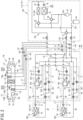
- FIG. 2 is a refrigerant circuit diagram of the air conditioning system 100.
- the outdoor unit 110 is installed in the outdoor space S2 such as on a roof or a balcony or underground of the building B.
- the outdoor unit 110 is provided therein with various constituents that are connected via refrigerant pipes to constitute a heat source refrigerant circuit RC1.
- the heat source refrigerant circuit RC1 is connected to an auxiliary refrigerant circuit RC2 in the first heat recovery unit 130 and an intermediate refrigerant circuit RC3 in the refrigerant flow path switching device 140 via a first connection pipe 11, a second connection pipe 12, and a third connection pipe 13.
- the heat source refrigerant circuit RC1 includes a liquid-side shutoff valve 21, a gas-side first shutoff valve 22, a gas-side second shutoff valve 23, an accumulator 24, a compressor 25, a first flow path switching valve 26, a second flow path switching valve 27, a third flow path switching valve 28, an outdoor heat exchanger 30, a first outdoor expansion valve 34, and a second outdoor expansion valve 35.
- the heat source refrigerant circuit RC1 is constituted by these constituents connected via a plurality of refrigerant pipes.
- the outdoor unit 110 is provided therein with an outdoor fan 33, a control unit 115 (see FIG. 7 ), and the like.
- the liquid-side shutoff valve 21, the gas-side first shutoff valve 22, and the gas-side second shutoff valve 23 are manually opened and closed upon refrigerant filling, pump down, and the like.
- the liquid-side shutoff valve 21 has a first end connected to the first connection pipe 11.
- the liquid-side shutoff valve 21 has a second end connected to a refrigerant pipe extending to the first outdoor expansion valve 34 and the second outdoor expansion valve 35.
- the gas-side first shutoff valve 22 has a first end connected to the second connection pipe 12.
- the gas-side first shutoff valve 22 has a second end connected to a refrigerant pipe extending to the second flow path switching valve 27.
- the gas-side second shutoff valve 23 has a first end connected to the third connection pipe 13.
- the gas-side second shutoff valve 23 has a second end connected to a refrigerant pipe 25c extending to the accumulator 24.
- the accumulator 24 is a container temporarily storing a low-pressure refrigerant to be sucked into the compressor 25 and used for separation between a gas refrigerant and a liquid refrigerant.
- the compressor 25 has a hermetic structure incorporating a compressor motor, and is of a positive displacement type such as a scroll type or a rotary type.
- the compressor 25 compresses a low-pressure refrigerant sucked from a suction pipe 25b and then discharges the compressed refrigerant from a discharge pipe 25a.
- the compressor 25 contains refrigerating machine oil. This refrigerating machine oil occasionally circulates in a refrigerant circuit along with the refrigerant.
- the outdoor unit 110 according to the present embodiment includes a single compressor 25.
- the outdoor unit 110 may alternatively include two or more compressors 25 connected in parallel.
- the first flow path switching valve 26, the second flow path switching valve 27, and the third flow path switching valve 28 are four-way switching valves. Each of the first flow path switching valve 26, the second flow path switching valve 27, and the third flow path switching valve 28 switches a refrigerant flow in accordance with an operation situation of the air conditioner 101. Each of the first flow path switching valve 26, the second flow path switching valve 27, and the third flow path switching valve 28 has a refrigerant inflow port connected with the discharge pipe 25a or a branching pipe extending from the discharge pipe 25a.
- Each of the first flow path switching valve 26, the second flow path switching valve 27, and the third flow path switching valve 28 has a refrigerant inflow port connected with a branching pipe extending from the refrigerant pipe 25c connecting the gas-side second shutoff valve 23 and the accumulator 24.
- Each of the first flow path switching valve 26, the second flow path switching valve 27, and the third flow path switching valve 28 is configured to shut off a refrigerant flow in a refrigerant flow path during operation, and actually functions as a three-way valve.
- the outdoor heat exchanger 30 is of a cross-fin type or a microchannel type.
- the outdoor heat exchanger 30 includes a first heat exchange unit 31 and a second heat exchange unit 32.
- the first heat exchange unit 31 is provided in an upper portion of the outdoor heat exchanger 30, and the second heat exchange unit 32 is provided below the first heat exchange unit 31.
- the first heat exchange unit 31 has a gas side end connected to a refrigerant pipe extending to the third flow path switching valve 28.
- the first heat exchange unit 31 has a liquid side end connected to a refrigerant pipe extending to the first outdoor expansion valve 34.
- the second heat exchange unit 32 has a gas side end connected to a refrigerant pipe extending to the first flow path switching valve 26.
- the second heat exchange unit 32 has a liquid side end connected to a refrigerant pipe extending to the second outdoor expansion valve 35.
- the refrigerant passing the first heat exchange unit 31 and the second heat exchange unit 32 exchanges heat with an air flow generated by the outdoor fan 33.
- the outdoor fan 33 is a propeller fan or the like, and is driven by an outdoor fan motor (not depicted).
- the outdoor fan 33 generates an air flow entering the outdoor unit 110, passing the outdoor heat exchanger 30, and flowing out of the outdoor unit 110.
- Examples of the first outdoor expansion valve 34 and the second outdoor expansion valve 35 include a motor valve having an adjustable opening degree.
- the first outdoor expansion valve 34 has a first end connected to a refrigerant pipe extending from the first heat exchange unit 31.
- the first outdoor expansion valve 34 has a second end connected to a refrigerant pipe extending to the liquid-side shutoff valve 21.
- the second outdoor expansion valve 35 has a first end connected to a refrigerant pipe extending from the second heat exchange unit 32.
- the second outdoor expansion valve 35 has a second end connected to a refrigerant pipe extending to the liquid-side shutoff valve 21.
- Each of the first outdoor expansion valve 34 and the second outdoor expansion valve 35 has an opening degree adjusted in accordance with an operation situation, and decompresses the refrigerant passing the corresponding outdoor expansion valve in accordance with the opening degree.
- the compressor 25, the outdoor fan 33, the first outdoor expansion valve 34, the second outdoor expansion valve 35, the first flow path switching valve 26, the second flow path switching valve 27, and the third flow path switching valve 28 are operation controlled by the control unit 115 (see FIG. 7 ).
- the control unit 115 in the outdoor unit 110 transmits and receives signals to and from an indoor control unit 54 (see FIG. 7 ) in each of the indoor units 120 and a control unit (not depicted) in the refrigerant flow path switching device 140 via communication lines.
- Each of the indoor units 120 is of a ceiling embedded type, a ceiling pendant type, a floor-standing type, or a wall mounted type.
- the air conditioning system 100 according to the present embodiment includes the two or more indoor units 120.
- Each of the indoor units 120 is provided therein with a utilization refrigerant circuit RC4.
- the utilization refrigerant circuit RC4 includes an indoor expansion valve 51 and an indoor heat exchanger 52.
- the utilization refrigerant circuit RC4 is constituted by the indoor expansion valve 51 and the indoor heat exchanger 52 connected via a refrigerant pipe.
- the indoor unit 120 is provided with an indoor fan 53 and the indoor control unit 54 (see FIG. 7 ).
- the indoor expansion valve 51 is a motor valve having an adjustable opening degree.
- the indoor expansion valve 51 has a first end connected to a liquid tube LP.
- the indoor expansion valve 51 has a second end connected to a refrigerant pipe extending to the indoor heat exchanger 52.
- the indoor expansion valve 51 decompresses the refrigerant passing therethrough in accordance with the opening degree.
- the indoor heat exchanger 52 is of a cross-fin type, a microchannel type, or the like.
- the indoor heat exchanger 52 has a liquid side end connected to a refrigerant pipe extending from the indoor expansion valve 51.
- the indoor heat exchanger 52 has a gas side end connected to a gas tube GP.
- the refrigerant having entered the indoor heat exchanger 52 exchanges heat with an air flow generated by the indoor fan 53 and is exhausted from the indoor heat exchanger 52.
- Examples of the indoor fan 53 include a cross-flow fan and a sirocco fan.
- the indoor fan 53 is driven by an indoor fan motor (not depicted).
- the indoor fan 53 generates an air flow entering the indoor unit 120 from an indoor space, passing the indoor heat exchanger 52, and then flowing out to the indoor space.
- the indoor expansion valve 51 and the indoor fan 53 are operation controlled by the indoor control unit 54 (see FIG. 7 ) in the indoor unit 120.
- the indoor control unit 54 is connected with the control unit 115 of the outdoor unit 110 and a remote controller (not depicted).
- the indoor control unit 54 drives the indoor fan 53 and the indoor expansion valve 51 in accordance with operating conditions such as set temperature inputted to the remote controller.
- the refrigerant flow path switching device 140 is provided between the outdoor unit 110 and the plurality of indoor units 120.
- the refrigerant flow path switching device 140 includes a casing 141.
- the refrigerant flow path switching device 140 switches flows of the refrigerant entering the outdoor unit 110 and the indoor units 120.
- the casing 141 accommodates a plurality of header pipes 55, 56, 57, and 58 and a plurality of switching units 70.
- the plurality of header pipes 55, 56, 57, and 58 includes a first header pipe 55, a second header pipe 56, a third header pipe 57, and a fourth header pipe 58.
- the first header pipe 55 is connected to the first connection pipe 11.
- the second header pipe 56 is connected to the second connection pipe 12.
- the third header pipe 57 is connected to the third connection pipe 13.
- the refrigerant flow path switching device 140 includes the plurality of switching units 70.
- the switching units 70 constitute the intermediate refrigerant circuit RC3 of the refrigerant flow path switching device 140.
- Each of the switching units 70 is connected with a single indoor unit 120. All the switching units 70 of the refrigerant flow path switching device 140 are not necessarily connected with the indoor units 120, and the refrigerant flow path switching device 140 may include a switching unit 70 not connected to any indoor unit 120.
- the plurality of switching units 70 is configured identically, and the intermediate refrigerant circuit RC3 in each of the switching units 70 includes a plurality of valves EV1, EV2, and EV3, and a plurality of refrigerant pipes.
- the plurality of valves EV1, EV2, and EV3 in each of the switching units 70 includes a first valve EV1, a second valve EV2, and a third valve EV3. These valves EV1, EV2, and EV3 are each constituted by a motor valve having an adjustable opening degree.
- Each of the second valve EV2 and the third valve EV3 is operation controlled by a control unit (not depicted) so as to come into a fully closed state, a fully opened state, or an opening degree adjusted state.
- the first valve EV1 is operation controlled by a control unit (not depicted) so as to come into a minimum opening degree state, the fully opened state, the fully closed state, or the opening degree adjusted state.
- the switching units 70 each include a first refrigerant tube P1 connecting the second header pipe 56 and the first valve EV1.
- the first refrigerant tube P1 has a halfway portion provided with a filter F1.
- the switching unit 70 includes a second refrigerant tube P2.
- the second refrigerant tube P2 has a first end connected to the first valve EV1.
- the switching unit 70 includes a utilization gas pipe 61.
- the utilization gas pipe 61 has a first end connected to the gas tube GP of the indoor unit 120.
- the utilization gas pipe 61 has a second end connected to the second valve EV2.
- the second refrigerant tube P2 has a second end connected to the utilization gas pipe 61.
- the utilization gas pipe 61 is provided with a filter F2.
- the switching unit 70 includes a third refrigerant tube P3.
- the third refrigerant tube P3 has a first end connected to the second valve EV2.
- the third refrigerant tube P3 has a second end connected to the third header pipe 57.
- the third refrigerant tube P3 has a halfway portion provided with a filter F3.
- the switching unit 70 includes a utilization liquid pipe 62.
- the utilization liquid pipe 62 has a first end connected to the liquid tube LP of the indoor unit 120.
- the utilization liquid pipe 62 has a second end connected to a subcooling heat exchanger 59.
- the subcooling heat exchanger 59 is provided therein with a first heat transfer tube 59a and a second heat transfer tube 59b.
- the subcooling heat exchanger 59 causes heat exchange between the refrigerant flowing in the first heat transfer tube 59a and the refrigerant flowing in the second heat transfer tube 59b.
- the utilization liquid pipe 62 has a second end connected to a first end of the first heat transfer tube 59a.
- the switching unit 70 includes a fourth refrigerant tube P4.
- the fourth refrigerant tube P4 has a first end connected to a second end of the first heat transfer tube 59a.
- the fourth refrigerant tube P4 has a second end connected to the first header pipe 55.
- the switching unit 70 includes a fifth refrigerant tube P5 branching from a halfway portion of the fourth refrigerant tube P4.
- the fifth refrigerant tube P5 has a first end connected to a first end of the third valve EV3.
- the fifth refrigerant tube P5 has a halfway portion provided with a filter F4.
- the switching unit 70 includes a sixth refrigerant tube P6 and a seventh refrigerant tube P7.
- the sixth refrigerant tube P6 has a first end connected to the third valve EV3.
- the sixth refrigerant tube P6 has a second end connected to a first end of the second heat transfer tube 59b of the subcooling heat exchanger 59.
- the seventh refrigerant tube P7 has a first end connected to the second heat transfer tube 59b of the subcooling heat exchanger 59.
- the seventh refrigerant tube P7 has a second end connected to the fourth header pipe 58.
- the fourth header pipe 58 is connected to the third header pipe 57 via a connecting tube 63.
- the fourth header pipe 58 receives the refrigerant flowing from the first header pipe 55 via the fourth refrigerant tube P4, the fifth refrigerant tube P5, the third valve EV3, the sixth refrigerant tube P6, the subcooling heat exchanger 59, and the seventh refrigerant tube P7.
- the refrigerant having entered the fourth header pipe 58 passes the connecting tube 63 and flows into the third header pipe 57.
- the first heat recovery unit 130 is configured to supply the indoor space S1 with cooled or heated air (outdoor air) and ventilate the indoor space S1 while recovering heat from air (exhaust air) exhausted from the indoor space S1, and is also referred to as an outdoor air treating unit.
- the first heat recovery unit 130 is disposed outside the indoor space S1 in the building B.
- the first heat recovery unit 130 is disposed in a ceiling space above the indoor space S1, and is connected to the indoor space S1 and the outdoor space S2 via ducts.
- the present embodiment exemplifies the case where the first heat recovery unit 130 is disposed in the ceiling space above the indoor space S1.
- the first heat recovery unit 130 may be of the ceiling pendant type, the ceiling embedded type, the floor-standing type, or the wall mounted type, and may be disposed at a position other than the ceiling space.
- the first heat recovery unit 130 includes an outdoor air treatment unit 130A including the auxiliary refrigerant circuit RC2, and an exhaust air treatment unit 130B.
- the outdoor air treatment unit 130A includes a supply air auxiliary heat exchanger 131 and a supply fan 137, and the supply air auxiliary heat exchanger 131 constitutes a first auxiliary refrigerant circuit RC21 as part of the auxiliary refrigerant circuit RC2.
- the exhaust air treatment unit 130B includes an exhaust air auxiliary heat exchanger 132 and an exhaust fan 138, and the exhaust air auxiliary heat exchanger 132 constitutes a second auxiliary refrigerant circuit RC22 as another part of the auxiliary refrigerant circuit RC2.
- Each of the supply air auxiliary heat exchanger 131 and the exhaust air auxiliary heat exchanger 132 is of the cross-fin type, the microchannel type, or the like.
- the supply air auxiliary heat exchanger 131 has a liquid side end connected to the first connection pipe 11 via a first branching pipe 14.
- the supply air auxiliary heat exchanger 131 has a gas side end connected to the third connection pipe 13 via a second branching pipe 15, or is connected to the second connection pipe 12 via a second branching pipe 15 and a fifth branching pipe 18.
- the first branching pipe 14 has a halfway portion provided with a first motor valve 136a.
- the second branching pipe 15 is connected with a first end of the fifth branching pipe 18.
- the fifth branching pipe 18 has a second end connected to the second connection pipe 12.
- the fifth branching pipe 18 has a halfway portion provided with a second switching valve 166.
- the exhaust air auxiliary heat exchanger 132 has a liquid side end connected to the first connection pipe 11 via a third branching pipe 16.
- the exhaust air auxiliary heat exchanger 132 has a gas side end connected to the third connection pipe 13 via a fourth branching pipe 17, or is connected to the second connection pipe 12 via the fourth branching pipe 17 and a sixth branching pipe 19.
- the third branching pipe 16 has a halfway portion provided with a second motor valve 136b.
- the fourth branching pipe 17 is connected with a first end of the sixth branching pipe 19.
- the sixth branching pipe 19 has a second end connected to the second connection pipe 12.
- the sixth branching pipe 19 has a halfway portion provided with a fourth switching valve 168.
- the first motor valve 136a is configured to control quantity of the refrigerant passing the supply air auxiliary heat exchanger 131.
- the second motor valve 136b is configured to control quantity of the refrigerant passing the exhaust air auxiliary heat exchanger 132.
- the first motor valve 136a and the second motor valve 136b each have an adjustable opening degree.
- the first auxiliary refrigerant circuit RC21 is connected to the first connection pipe 11 via the first branching pipe 14, is connected to the third connection pipe 13 via the second branching pipe 15, and is connected to the second connection pipe 12 via the second branching pipe 15 and the fifth branching pipe 18.
- the second auxiliary refrigerant circuit RC22 is connected to the first connection pipe 11 via the third branching pipe 16, is connected to the third connection pipe 13 via the fourth branching pipe 17, and is connected to the second connection pipe 12 via the fourth branching pipe 17 and the sixth branching pipe 19.
- the first heat recovery unit 130 is provided therein with the supply fan 137 and the exhaust fan 138.
- the supply fan 137 constitutes part of the outdoor air treatment unit 130A
- the exhaust fan 138 constitutes part of the exhaust air treatment unit 130B.
- Examples of the supply fan 137 and the exhaust fan 138 include a sirocco fan.
- the supply fan 137 is driven by a supply fan motor (not depicted).
- the supply fan 137 generates an air flow entering the first heat recovery unit 130 from the outdoor space S2 (see FIG. 1 ), passing the supply air auxiliary heat exchanger 131, and then flowing out to the first space S11 (see FIG. 1 ).
- the exhaust fan 138 is driven by an exhaust fan motor (not depicted).
- the exhaust fan 138 generates an air flow entering the first heat recovery unit 130 from the first space S11 (see FIG. 1 ), passing the exhaust air auxiliary heat exchanger 132, and then flowing out to the outdoor space S2 (see FIG. 1 ).
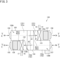
- FIG. 3 depicts a return air intake port 157 provided to import air (return air) RA from the indoor space S1 (see FIG. 1 ) into a casing 150.
- the return air intake port 157 is connected to the indoor space S1 via a duct or the like (not depicted).
- an exhaust air blow-out port 155 to exhaust, as exhaust air EA, the return air RA imported into the casing 150, to the outdoor space S2 (see FIG. 1 ).
- the exhaust air blow-out port 155 is connected to the outdoor space S2 via a duct or the like (not depicted).
- the outdoor air intake port 158 is connected to the outdoor space S2 via a duct or the like (not depicted). There is provided a supply air blow-out port 156 to supply the indoor space S1 with the outdoor air OA imported into the casing 150 as supply air SA. The supply air blow-out port 156 is connected to the indoor space S1 via a duct or the like (not depicted).
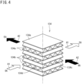
- FIG. 4 is a perspective view of a heat exchange unit.
- FIG. 4 depicts a heat exchange unit 134 according to the present embodiment, as a perpendicular total heat exchanger configured to have a first air flow A1 and a second air flow A2 running substantially perpendicularly to each other.
- the heat exchange unit 134 includes partition plates 134a and partition wall plates 134b.
- the partition plates 134a and the partition wall plates 134b are alternately stacked with use of an appropriate adhesive.
- the heat exchange unit 134 entirely has a substantially quadrangular prism shape.
- Each of the partition plates 134a has a heat transfer property and moisture permeability, and is formed into a flat plate shape.
- Each of the partition wall plates 134b is formed into a corrugated plate shape continuously having substantially triangular sections.
- Each of the partition wall plates 134b forms an air passage between two of the partition plates 134a adjacent to each other.
- the partition wall plates 134b are stacked so as to be turned by 90 degrees one by one in a stacking direction (a vertical direction in FIG. 4 ) of the partition plates 134a and the partition wall plates 134b. There are thus provided a supply air passage 134d for the first air flow A1 and an exhaust air passage 134c for the second air flow A2.
- the supply air passage 134d and the exhaust air passage 134c interpose a single partition plate 134a, and are disposed perpendicularly to each other. Air flowing in the exhaust air passage 134c and air flowing in the supply air passage 134d are to exchange sensible heat and latent heat (total heat exchange) via the partition plate 134a having the heat transfer property and the moisture permeability.
- the first heat recovery unit 130 recovers heat with use of the refrigerant flowing in the first auxiliary refrigerant circuit RC21 and the heat exchange unit 134 further recovers heat between air flows (the return air RA and the outdoor air OA) in the casing 150, to achieve better operation efficiency of the air conditioner 101.
- FIG. 5 is a schematic explanatory sectional view taken along line X-X indicated in FIG. 3 .
- FIG. 6 is a schematic explanatory sectional view taken along line Y-Y indicated in FIG. 3 .
- the first heat recovery unit 130 includes the casing 150.
- the casing 150 has the interior sectioned by the heat exchange unit 134 into two regions, specifically, a region adjacent to the indoor space S1 and a region adjacent to the outdoor space S2. As depicted in FIG.
- the casing 150 is provided therein with an upstream supply air passage 151a disposed upstream of the heat exchange unit 134 on the first air flow A1, and a downstream supply air passage 151b disposed downstream of the heat exchange unit 134 on the first air flow A1.
- the upstream supply air passage 151a and the downstream supply air passage 151b constitute a supply air passage 151 causing the indoor space S1 and the outdoor space S2 to communicate with each other via the heat exchange unit 134.
- the casing 150 is provided therein with an upstream exhaust air passage 152a disposed upstream of the heat exchange unit 134 on the second air flow A2, and a downstream exhaust air passage 152b disposed downstream of the heat exchange unit 134 on the second air flow A2.
- the upstream exhaust air passage 152a and the downstream exhaust air passage 152b constitute an exhaust air passage 152 causing the indoor space S1 and the outdoor space S2 to communicate with each other via the heat exchange unit 134.
- the downstream supply air passage 151b and the upstream exhaust air passage 152a interpose a sectioning wall 153.
- the upstream supply air passage 151a and the downstream exhaust air passage 152b interpose a sectioning wall 154.
- the downstream supply air passage 151b is provided, adjacent to the supply air blow-out port 156, with the supply fan 137 and the supply air auxiliary heat exchanger 131.
- the supply fan 137 operates to generate the first air flow A1, and the outdoor air OA in the outdoor space S2 passes the supply air passage 151 to exchange heat in the supply air auxiliary heat exchanger 131 and be supplied into the indoor space S1 as the supply air SA.
- the supply air auxiliary heat exchanger 131 causes heat exchange (heat recovery) between the refrigerant flowing in the first auxiliary refrigerant circuit RC21 and air (the outdoor air OA) passing the supply air passage 151.
- the downstream exhaust air passage 152b is provided, adjacent to the exhaust air blow-out port 155, with the exhaust fan 138 and the exhaust air auxiliary heat exchanger 132.
- the exhaust fan 138 operates to generate the second air flow A2, and the return air RA from the indoor space S 1 passes the exhaust air passage 152 to exchange heat in the exhaust air auxiliary heat exchanger 132 and be exhausted as the exhaust air EA to the outdoor space S2.
- the exhaust air auxiliary heat exchanger 132 causes heat exchange (heat recovery) between the refrigerant flowing in the second auxiliary refrigerant circuit RC22 and air (the exhaust air EA) passing the exhaust air passage 152.
- the first heat recovery unit 130 includes the casing 150 accommodating the first auxiliary refrigerant circuit RC21, the second auxiliary refrigerant circuit RC22, the supply fan 137, and the exhaust fan 138, and provided with the supply air passage 151 for air passing the supply air auxiliary heat exchanger 131 and the exhaust air passage 152 for air passing the exhaust air auxiliary heat exchanger 132, and the heat exchange unit 134 configured to cause heat exchange between air existing in the supply air passage 151 and being subject to passing the supply air auxiliary heat exchanger 131 and air existing in the exhaust air passage 152 and being subject to passing the exhaust air auxiliary heat exchanger 132.
- the single casing 150 accommodates the outdoor air treatment unit 130A and the exhaust air treatment unit 130B in the first heat recovery unit 130, and the heat exchange unit 134, to simplify a pipe configuration around the outdoor air treatment unit 130A and the exhaust air treatment unit 130B.
- This facilitates connecting work for the heat source refrigerant circuit RC1, the first auxiliary refrigerant circuit RC21, and the second auxiliary refrigerant circuit RC22.
- the present embodiment exemplifies the first heat recovery unit 130 including the outdoor air treatment unit 130A and the exhaust air treatment unit 130B.
- the heat recovery unit according to the present disclosure may include only the outdoor air treatment unit 130A.
- the present embodiment exemplifies the first heat recovery unit 130 including the single casing 150 accommodating the outdoor air treatment unit 130A and the exhaust air treatment unit 130B.
- the outdoor air treatment unit and the exhaust air treatment unit may be separated from each other to be disposed at different positions.
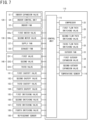
- FIG. 7 is a control block diagram of the air conditioning system 100.
- the air conditioning system 100 includes the control unit 115.
- the control unit 115 is configured to control behavior of the air conditioner 101 and the refrigerant flow path switching device 140, and is exemplarily constituted by a microcomputer including a processor such as a CPU and a memory such as a RAM or a ROM.
- the control unit 115 may alternatively be embodied as hardware with use of an LSI, an ASIC, an FPGA, or the like.
- the control unit 115 exerts a predetermined function when the processor executes a program installed in the memory.
- the control unit 115 may be provided integrally with the air conditioner 101 as part of the air conditioner 101, or may be provided separately from the air conditioner 101 as a separate device.
- the control unit 115 is provided in the outdoor unit 110.
- the control unit 115 is connected with the compressor 25, the first flow path switching valve 26, the second flow path switching valve 27, the third flow path switching valve 28, the outdoor fan 33, the first outdoor expansion valve 34, the second outdoor expansion valve 35, and a temperature sensor 116, which are incorporated in the outdoor unit 110.
- the control unit 115 is connected with the indoor expansion valve 51 and the indoor fan 53 via the indoor control unit 54 in the indoor unit 120.
- the control unit 115 is connected with the first and second motor valves 136a and 136b, the supply fan 137, and the exhaust fan 138 of the first heat recovery unit 130.
- the control unit 115 may alternatively be connected to an auxiliary heat exchanger switching valve 133, the motor valves 136a and 136b, the supply fan 137, and the exhaust fan 138 via a control unit (not depicted) of the first heat recovery unit 130.
- the control unit 115 is connected with the first valve EV1, the second valve EV2, and the third valve EV3 via the control unit (not depicted) of the refrigerant flow path switching device 140 (the switching unit 70).
- the control unit 115 is connected with first to fourth shutoff valves 161 to 164, the first switching valve 165, and the second switching valve 166.
- the control unit 115 is connected with the temperature sensor 116 and a refrigerant sensor 180.
- the control unit 115 controls behavior of the above connected constituents in accordance with an operation situation of the air conditioning system 100.
- the air conditioning system 100 includes the four shutoff valves 161 to 164.
- the first to fourth shutoff valves 161 to 164 are configured as motor valves.
- the first shutoff valve 161 is disposed on the first branching pipe 14
- the second shutoff valve 162 is disposed on the second branching pipe 15
- the third shutoff valve 163 is disposed on the third branching pipe 16
- the fourth shutoff valve 164 is disposed on the fourth branching pipe 17.
- the refrigerant sensor 180 (see FIG. 7 ) is disposed at a position enabling sensing of any refrigerant leaking from the first heat recovery unit 130.
- the control unit 115 operates all the shutoff valves 161 to 164.
- the auxiliary refrigerant circuit RC2 (the first auxiliary refrigerant circuit RC21 and the second auxiliary refrigerant circuit RC22) of the first heat recovery unit 130 is completely separated from the remaining refrigerant circuits RC1, RC3, and RC4.
- the air conditioning system 100 can thus inhibit leakage from the first heat recovery unit 130 of the refrigerant having quantity exceeding the refrigerant being stored in the auxiliary refrigerant circuit RC2.
- the refrigerant sensor 180 may alternatively be provided on each of the supply air passage 151 and the exhaust air passage 152.
- shutoff valves 161 and 162 adjacent to the supply air passage 151 may be shut off when the refrigerant sensor 180 on the supply air passage 151 senses any refrigerant, and only the shutoff valves 163 and 164 adjacent to the exhaust air passage 152 may be shut off when the refrigerant sensor 180 on the exhaust air passage 152 senses any refrigerant.
- the control unit 115 adjusts the valves as follows.
- the first valve EV1 is fully closed, the second valve EV2 is fully opened, and the third valve EV3 is adjusted in opening degree.
- the indoor expansion valve 51 is adjusted in opening degree, and the first and second outdoor expansion valves 34 and 35 are fully opened.
- the shutoff valves 161 to 164 are fully opened, and the first motor valve 136a and the second motor valve 136b are adjusted in opening degree.
- the first flow path switching valve 26 in the outdoor unit 110 is switched to connect the discharge pipe 25a of the compressor 25 and the gas side end of the second heat exchange unit 32.
- the second flow path switching valve 27 is switched to connect the discharge pipe 25a and the second connection pipe 12.
- the third flow path switching valve 28 is switched to connect the discharge pipe 25a and the gas side end of the first heat exchange unit 31.
- the air conditioning system 100 may not include the second flow path switching valve 27 because a high-pressure gas refrigerant may constantly flow in the second connection pipe 12.
- the second flow path switching valve 27 is switched when the first valve EV1 connected to the second connection pipe 12 has the minimum opening degree and the high-pressure gas refrigerant does not need to flow in the second connection pipe 12, to prevent refrigerant accumulation between the first valve EV1 and the second flow path switching valve 27.
- the control unit 115 causes the indoor expansion valve 51 to be fully closed, causes the first valve EV1 corresponding to this indoor unit 120 to have the minimum opening degree, and causes the second valve EV2 and the third valve EV3 to be fully closed.
- a high-pressure gas refrigerant compressed by the compressor 25 passes the discharge pipe 25a, the first flow path switching valve 26, the third flow path switching valve 28, and the like, and then flows into the outdoor heat exchanger 30 to be condensed.
- the refrigerant condensed in the outdoor heat exchanger 30 passes the first and second outdoor expansion valves 34 and 35, the liquid-side shutoff valve 21, and the like, to flow into the first connection pipe 11.
- the refrigerant having entered the first connection pipe 11 flows in the first header pipe 55 of the refrigerant flow path switching device 140, and flows into the fourth refrigerant tube P4 of each of the switching units 70.
- the refrigerant having entered the fourth refrigerant tube P4 flows into the first heat transfer tube 59a of the subcooling heat exchanger 59, and then passes the utilization liquid pipe 62 to flow into the indoor unit 120.
- the refrigerant having entered the fourth refrigerant tube P4 also branches into the fifth refrigerant tube P5, is decompressed in accordance with the opening degree of the third valve EV3, and flows into the second heat transfer tube 59b of the subcooling heat exchanger 59.
- the refrigerant flowing in the first heat transfer tube 59a and the refrigerant flowing in the second heat transfer tube 59b exchange heat with each other in the subcooling heat exchanger 59, and the refrigerant flowing in the first heat transfer tube 59a is subcooled and flows into the indoor unit 120.
- the refrigerant flowing in the second heat transfer tube 59b of the subcooling heat exchanger 59 flows from the seventh refrigerant tube P7 into the fourth header pipe 58, passes the connecting tube 63, and flows into the third header pipe 57.
- the refrigerant having entered the indoor unit 120 is decompressed at the indoor expansion valve 51 and is then evaporated in the indoor heat exchanger 52.
- the refrigerant evaporated in the indoor heat exchanger 52 flows from the gas tube GP into the utilization gas pipe 61, mainly passes the second valve EV2 and flows into the third header pipe 57.
- the refrigerant having entered the third header pipe 57 passes the third connection pipe 13 and the gas-side second shutoff valve 23, and then flows into the accumulator 24 to be sucked in to the compressor 25.
- the supply air auxiliary heat exchanger 131 is thus supplied with a liquid refrigerant from the first connection pipe 11 and the first branching pipe 14, and the liquid refrigerant flows into the supply air auxiliary heat exchanger 131.
- the liquid refrigerant exchanges heat with air (the outdoor air OA) in the supply air auxiliary heat exchanger 131 to be evaporated into a low-pressure gas refrigerant.
- the gas refrigerant flows from the second branching pipe 15 into the third connection pipe 13.
- the first heat recovery unit 130 cools the outdoor air OA in this manner during cooling operation, and supplies the first space S11 with the supply air SA.
- the third switching valve 167 is closed whereas the fourth switching valve 168 is opened.
- the exhaust air auxiliary heat exchanger 132 in the first heat recovery unit 130 is thus supplied with a high-pressure gas refrigerant from the second connection pipe 12, the sixth branching pipe 19, and the fourth branching pipe 17, and the gas refrigerant flows into the exhaust air auxiliary heat exchanger 132.
- the gas refrigerant exchanges heat with air (the exhaust air EA) in the exhaust air auxiliary heat exchanger 132 to be condensed into a liquid refrigerant.
- the liquid refrigerant flows from the third branching pipe 16 into the first connection pipe 11.
- the first heat recovery unit 130 recovers heat from the return air RA as well as discharges the exhaust air EA to the outdoor space S2 during cooling operation.
- a high-pressure gas refrigerant flowing to the second connection pipe 12 via the second flow path switching valve 27 does not flow into the indoor unit 120 because the first valve EV1 is fully closed.
- the control unit 115 adjusts the valves as follows.
- the first valve EV1 is fully opened, the second valve EV2 is fully closed, and the third valve EV3 is fully closed.
- the indoor expansion valve 51 is fully opened, and the first and second outdoor expansion valves 34 and 35 are adjusted in opening degree.
- the shutoff valves 161 to 164 are fully opened, and the first motor valve 136a and the second motor valve 136b are adjusted in opening degree.
- the first flow path switching valve 26 in the outdoor unit 110 is switched to connect the refrigerant pipe 25c and the gas side end of the second heat exchange unit 32.
- the second flow path switching valve 27 is switched to connect the discharge pipe 25a and the second connection pipe 12.
- the third flow path switching valve 28 is switched to connect the refrigerant pipe 25c and the gas side end of the first heat exchange unit 31.
- the high-pressure gas refrigerant compressed by the compressor 25 passes the discharge pipe 25a, the second flow path switching valve 27, and the like, and then flows into the second connection pipe 12.
- the refrigerant having entered the second connection pipe 12 passes the first valve EV1 via the second header pipe 56 of the refrigerant flow path switching device 140 and the first refrigerant tube P1 of the switching unit 70, and flows from the utilization gas pipe 61 into the gas tube GP of the indoor unit 120.
- the refrigerant having entered the gas tube GP flows into the indoor heat exchanger 52 of the indoor unit 120 to be condensed.
- the condensed refrigerant passes the indoor expansion valve 51, flows in the liquid tube LP, and flows into the utilization liquid pipe 62 of the switching unit 70.
- the refrigerant having entered the utilization liquid pipe 62 passes the subcooling heat exchanger 59 and the fourth refrigerant tube P4, and flows into the first header pipe 55.
- the refrigerant having entered the first header pipe 55 flows in the first connection pipe 11, flows into the outdoor unit 110, and is decompressed at the first and second outdoor expansion valves 34 and 35.
- the decompressed refrigerant is evaporated while passing the outdoor heat exchanger 30, passes the first flow path switching valve 26, the third flow path switching valve 28, and the like, then flows into the accumulator 24, and is sucked into the compressor 25.
- the supply air auxiliary heat exchanger 131 is thus supplied with a high-pressure gas refrigerant from the second connection pipe 12, the fifth branching pipe 18, and the second branching pipe 15, and the gas refrigerant flows into the supply air auxiliary heat exchanger 131.
- the gas refrigerant exchanges heat with air (the outdoor air OA) in the supply air auxiliary heat exchanger 131 to be condensed into a liquid refrigerant.
- the liquid refrigerant flows from the first branching pipe 14 into the first connection pipe 11.
- the first heat recovery unit 130 heats the outdoor air OA in this manner during heating operation, and supplies the first space S11 with the supply air SA.
- the exhaust air auxiliary heat exchanger 132 of the first heat recovery unit 130 is supplied with a liquid refrigerant from the first connection pipe 11 and the third branching pipe 16, and the liquid refrigerant flows into the exhaust air auxiliary heat exchanger 132.
- the liquid refrigerant exchanges heat with air (the exhaust air EA) in the exhaust air auxiliary heat exchanger 132 to be evaporated into a gas refrigerant.
- the gas refrigerant flows from the fourth branching pipe 17 into the third connection pipe 13. In this manner, the first heat recovery unit 130 recovers heat from the return air RA as well as discharges the exhaust air EA to the outdoor space S2 during heating operation.
- the control unit 115 adjusts the valves as follows.
- the switching unit 70 (hereinafter, also referred to as a "cooling switching unit 70") corresponding to the indoor unit 120 (hereinafter, also referred to as a “cooling indoor unit 120”) executing cooling operation among the indoor units 120 in operation
- the first valve EV1 has the minimum opening degree
- the second valve EV2 is fully opened
- the third valve EV3 is adjusted in opening degree
- the indoor expansion valve 51 in the cooling indoor unit 120 is adjusted in opening degree.
- the shutoff valves 161 to 164 are fully opened
- the first motor valve 136a and the second motor valve 136b are adjusted in opening degree.
- the first flow path switching valve 26 in the outdoor unit 110 is switched to connect the refrigerant pipe 25c and the gas side end of the second heat exchange unit 32.
- the second flow path switching valve 27 is switched to connect the discharge pipe 25a and the second connection pipe 12.
- the third flow path switching valve 28 is switched to connect the discharge pipe 25a and the gas side end of the first heat exchange unit 31.
- the switching unit 70 (hereinafter, also referred to as a “heating switching unit 70") corresponding to the indoor unit 120 (hereinafter, also referred to as a “heating indoor unit 120”) executing heating operation among the indoor units 120 in operation
- the first valve EV1 is fully opened
- the second valve EV2 is fully closed
- the third valve EV3 is fully closed
- the indoor expansion valve 51 in the heating indoor unit 120 is fully opened
- the first outdoor expansion valve 34 and the second outdoor expansion valve 35 are adjusted in opening degree.
- the indoor unit 120 (the cooling indoor unit 120) in the first space S11 executes cooling operation
- the indoor unit 120 (the heating indoor unit 120) in the second space S12 executes heating operation.
- the supply air auxiliary heat exchanger 131 functions as an evaporator correspondingly to the cooling indoor unit 120 in the first space S11, and the exhaust air auxiliary heat exchanger 132 functions as a condenser.
- part of the high-pressure gas refrigerant compressed by the compressor 25 passes the discharge pipe 25a and the second flow path switching valve 27, and then flows into the second connection pipe 12.
- Another part of the high-pressure gas refrigerant compressed by the compressor 25 passes the discharge pipe 25a and the third flow path switching valve 28, is condensed in the first heat exchange unit 31 of the outdoor heat exchanger 30, and passes the first outdoor expansion valve 34, and part thereof flows into the first connection pipe 11 whereas another part thereof flows into the second outdoor expansion valve 35.
- the refrigerant condensed in the first heat exchange unit 31 passes the second outdoor expansion valve 35, is evaporated in the second heat exchange unit 32, passes the first flow path switching valve 26, and is sucked into the compressor 25.
- both the first heat exchange unit 31 and the second heat exchange unit 32 may function as a condenser or an evaporator in accordance with the balance between quantity of the condensed refrigerant and quantity of the evaporated refrigerant in the indoor unit 120 and the first heat recovery unit 130.
- the refrigerant having entered the second connection pipe 12 flows into the second header pipe 56 of the refrigerant flow path switching device 140, flows in the first refrigerant tube P1, the first valve EV1, and the utilization gas pipe 61 of the heating switching unit 70, and flows into the gas tube GP.
- the refrigerant having entered the gas tube GP is condensed in the indoor heat exchanger 52 of the heating indoor unit 120.
- the condensed refrigerant flows from the liquid tube LP into the utilization liquid pipe 62 of the heating switching unit 70, flows in the subcooling heat exchanger 59 and the fourth refrigerant tube P4, and flows into the first header pipe 55.
- the refrigerant having entered the first connection pipe 11 from the outdoor unit 110 also flows into the first header pipe 55.
- the refrigerant having entered the first header pipe 55 passes the fourth refrigerant tube P4 of the cooling switching unit 70, the subcooling heat exchanger 59, the utilization liquid pipe 62, and the liquid tube LP, and flows into the cooling indoor unit 120.
- the refrigerant having passed the subcooling heat exchanger 59 is subcooled by the refrigerant that flowed in the fifth refrigerant tube P5 branched from the fourth refrigerant tube P4, and that decompressed at the third valve EV3.
- the refrigerant having entered the cooling indoor unit 120 is decompressed at the indoor expansion valve 51, and is evaporated in the indoor heat exchanger 52 to cool the indoor space.
- the evaporated refrigerant flows in the gas tube GP, flows into the utilization gas pipe 61 of the cooling switching unit 70, passes the second valve EV2, flows into the third refrigerant tube P3 and the third header pipe 57, flows in the third connection pipe 13, and flows into the accumulator 24 to be sucked into the compressor 25.
- the supply air auxiliary heat exchanger 131 functions as an evaporator correspondingly to the cooling indoor unit 120 in the first space S11, cools the outdoor air OA, and supplies the first space S11 with the supply air SA.
- the exhaust air auxiliary heat exchanger 132 functions as a condenser, recovers heat from the return air RA to evaporate a gas refrigerant, and discharges the return air RA increased in temperature as the exhaust air EA to the outdoor space S2.
- the outdoor unit 110 is provided with the temperature sensor 116 (see FIG. 7 ).
- the temperature sensor 116 measures air temperature (outdoor air temperature T) in the outdoor space S2.
- the temperature sensor 116 may be disposed in the outdoor space S2 other than the outdoor unit 110.
- the control unit 115 determines that outdoor air cooling operation is executable for the indoor space S1 when the outdoor air temperature T is less than predetermined set temperature TS.
- the set temperature TS is preliminarily stored in the control unit 115.
- the set temperature TS can be changed by operating the control unit 115.
- the indoor unit 120 continuously executes cooling operation in the second space S12 and outdoor air cooling operation for the first space S11 is executed with use of the first heat recovery unit 130.
- the control unit 115 determines that outdoor air cooling operation is executable, the air conditioning system 100 switches behavior of the respective constituents as follows.
- the control unit 115 in the air conditioning system 100 stops the indoor unit 120 and causes the first heat recovery unit 130 to continuously ventilate. Furthermore, the control unit 115 closes the first shutoff valve 161 and the second shutoff valve 162, and operates the supply fan 137. This leads to switching an air conditioning mode for the first space S11 from normal cooling operation to outdoor air cooling operation.
- the air conditioning system 100 shuts off the refrigerant passing the supply air auxiliary heat exchanger 131.
- the air conditioning system 100 can thus operate only the supply fan 137 without heat exchange by the supply air auxiliary heat exchanger 131, for efficient operation of the air conditioning system 100.
- the present embodiment exemplifies the case where the air conditioning system 100 automatically executes outdoor air cooling operation in accordance with a measurement value of the outdoor air temperature T.
- the air conditioning system according to the present disclosure may be configured to manually switch to outdoor air cooling operation in accordance with a user command.
- control unit 115 keeps the third shutoff valve 163 and the fourth shutoff valve 164 "opened” to continue refrigerant supply to the exhaust air auxiliary heat exchanger 132.
- the exhaust air auxiliary heat exchanger 132 in the first heat recovery unit 130 is supplied with a high-pressure gas refrigerant from the second connection pipe 12 and the fourth branching pipe 17, and the gas refrigerant flows into the exhaust air auxiliary heat exchanger 132.
- the gas refrigerant exchanges heat with air (the exhaust air EA) in the exhaust air auxiliary heat exchanger 132 to be condensed into a liquid refrigerant.
- the liquid refrigerant flows from the third branching pipe 16 into the first connection pipe 11. In this manner, the first heat recovery unit 130 can continuously recover heat from the return air RA during outdoor air cooling operation.
- the air conditioning system 100 is configured to execute outdoor air cooling operation for the first space S11, and further recover heat from the exhaust air EA of the first space S11 with use of the exhaust air auxiliary heat exchanger 132. This enables further efficient operation of the air conditioning system 100. Provision of the fourth shutoff valve 164 is preferred for suppression in quantity of the refrigerant leaking from the first heat recovery unit 130. Alternatively, the fourth shutoff valve 164 may be excluded in a configuration achieving heat recovery by the exhaust air treatment unit 130B during outdoor air cooling operation.
- the present embodiment exemplifies the air conditioning system 100 adopting R32 having slight combustibility as the refrigerant. Alternatively, the air conditioning system according to the present disclosure may adopt a noncombustible refrigerant.
- the air conditioning system 100 further includes the indoor unit 120 disposed in the second space S12 different from the first space S11.
- the utilization refrigerant circuit RC4 in the indoor unit 120 configured to condition air in the second space S12 is individually connected to the heat source refrigerant circuit RC1 by the first connection pipe 11 and the third connection pipe 13.
- the air conditioning system 100 can thus execute outdoor air cooling operation for the first space S11 with use of the first heat recovery unit 130 as well as can continue cooling operation in the second space S12, of the indoor unit 120 for the second space S12.
- FIG. 8 is a schematic diagram depicting an entire configuration of an air conditioning system according to the second embodiment of the present disclosure.
- FIG. 9 is a refrigerant circuit diagram of the air conditioning system according to the second embodiment.
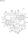
- FIG. 10 is a schematic configuration diagram of a heat recovery unit according to the second embodiment.
- the present disclosure provides an air conditioning system 200 according to the second embodiment, including an air conditioner 102 and a refrigerant flow path switching device 140.
- the air conditioning system 200 is different from the air conditioning system 100 according to the first embodiment in that the air conditioner 102 is provided in place of the air conditioner 101.
- constituents same as the constituents described with reference to FIG. 1 to FIG. 7 are denoted by identical reference signs, and the following description will not refer to the constituents denoted by the identical reference signs unless otherwise specifically described.
- the air conditioner 102 includes the outdoor unit 110, the indoor unit 120, and a second heat recovery unit 170.
- the air conditioner 102 two or more indoor units 120 and a single second heat recovery unit 170 are connected to the single outdoor unit 110.
- the refrigerant flow path switching device 140 is configured to freely select cooling operation or heating operation for each of the indoor units 120 to achieve air conditioning of the target space.
- the air conditioner 102 is different from the air conditioner 101 according to the first embodiment in that the second heat recovery unit 170 is provided in place of the first heat recovery unit 130.
- the second heat recovery unit 170 is configured to ventilate the indoor space S1, and is disposed outside the indoor space S1 in the building B.
- the second heat recovery unit 170 is disposed in a ceiling space above the indoor space S1, and is connected to the indoor space S1 and the outdoor space S2 via ducts.
- the present embodiment exemplifies the case where the second heat recovery unit 170 is disposed in the ceiling space above the indoor space S1.
- the second heat recovery unit according to the present disclosure may be of the ceiling pendant type, the ceiling embedded type, the floor-standing type, or the wall mounted type, and may be disposed at a position other than the ceiling space. As depicted in FIG.
- the second heat recovery unit 170 includes the supply air auxiliary heat exchanger 131, the exhaust air auxiliary heat exchanger 132, the auxiliary heat exchanger switching valve 133, and the heat exchange unit 134.
- the second heat recovery unit 170 includes an outdoor air treatment unit 170A and an exhaust air treatment unit 170B.
- the outdoor air treatment unit 170A includes the supply air auxiliary heat exchanger 131, whereas the exhaust air treatment unit 170B includes the exhaust air auxiliary heat exchanger 132.
- the second heat recovery unit 170 is provided therein with a third auxiliary refrigerant circuit RC5.
- the third auxiliary refrigerant circuit RC5 is constituted by the supply air auxiliary heat exchanger 131, the exhaust air auxiliary heat exchanger 132, and the auxiliary heat exchanger switching valve 133 connected by an auxiliary refrigerant pipe 135.
- the auxiliary refrigerant pipe 135 includes a first auxiliary refrigerant tube 135a, a second auxiliary refrigerant tube 135b, a third auxiliary refrigerant tube 135c, a fourth auxiliary refrigerant tube 135d, and a fifth auxiliary refrigerant tube 135e.
- the supply air auxiliary heat exchanger 131 has a first side end connected to the third auxiliary refrigerant tube 135c extending from the auxiliary heat exchanger switching valve 133.
- the supply air auxiliary heat exchanger 131 has a second side end connected to a first end of the second auxiliary refrigerant tube 135b.
- the second auxiliary refrigerant tube 135b has a second end connected to a first side end of the exhaust air auxiliary heat exchanger 132.
- the second auxiliary refrigerant tube 135b has a halfway portion provided with a motor valve 139.
- the motor valve 139 has an adjustable opening degree.
- the exhaust air auxiliary heat exchanger 132 has a second side end connected to the first auxiliary refrigerant tube 135a extending from the auxiliary heat exchanger switching valve 133.
- the auxiliary heat exchanger switching valve 133 is a four-way switching valve having four ports connected respectively with the first auxiliary refrigerant tube 135a, the second auxiliary refrigerant tube 135b, the fourth auxiliary refrigerant tube 135d, and the fifth auxiliary refrigerant tube 135e.
- the fourth auxiliary refrigerant tube 135d is connected to a seventh branching pipe 191
- the fifth auxiliary refrigerant tube 135e is connected to an eighth branching pipe 192.
- the auxiliary heat exchanger switching valve 133 switches refrigerant flows among the first auxiliary refrigerant tube 135a, the second auxiliary refrigerant tube 135b, the fourth auxiliary refrigerant tube 135d, and the fifth auxiliary refrigerant tube 135e.
- the third auxiliary refrigerant circuit RC5 is connected to the second connection pipe 12 on a high-pressure gas side via the seventh branching pipe 191, and is connected to the third connection pipe 13 on a low-pressure gas side via the eighth branching pipe 192.
- FIG. 11 is a control block diagram of the air conditioning system 200.
- the control unit 115 in the air conditioning system 200 is connected with the compressor 25, the first flow path switching valve 26, the second flow path switching valve 27, the third flow path switching valve 28, the outdoor fan 33, the first outdoor expansion valve 34, and the second outdoor expansion valve 35, which are incorporated in the outdoor unit 110.
- the control unit 115 is connected with the indoor expansion valve 51 and the indoor fan 53 via the indoor control unit 54 in the indoor unit 120.
- the control unit 115 is connected with the auxiliary heat exchanger switching valve 133 of the second heat recovery unit 170, the motor valve 139, the supply fan 137, and the exhaust fan 138.
- the control unit 115 is connected with the first valve EV1, the second valve EV2, and the third valve EV3 via the control unit (not depicted) of the refrigerant flow path switching device 140 (the switching unit 70).
- the control unit 115 is connected with a fifth shutoff valve 193 and a sixth shutoff valve 194.
- the control unit 115 is connected with the temperature sensor 116 and the refrigerant sensor 180.
- the control unit 115 controls behavior of the above connected constituents in accordance with an operation situation of the air conditioning system 200.
- the second heat recovery unit 170 may include a control unit (not depicted), and the control unit 115 may be connected with the auxiliary heat exchanger switching valve 133, the motor valve 139, the supply fan 137, and the exhaust fan 138 via the control unit (not depicted) of the second heat recovery unit 170.
- the air conditioning system 200 Upon execution of outdoor air cooling operation, the air conditioning system 200 stops the indoor unit 120 and continues ventilation with use of the second heat recovery unit 170. Specifically in the air conditioning system 200, if the outdoor air temperature T detected by the temperature sensor 116 is less than the set temperature TS while the indoor unit 120 is cooling the first space S11, the control unit 115 closes the fifth shutoff valve 193 and the sixth shutoff valve 194 and operates the supply fan 137. The air conditioning system 200 can thus switch air conditioning for the first space S11 from normal cooling operation to outdoor air cooling operation.
- the air conditioning system 200 shuts off the refrigerant passing the supply air auxiliary heat exchanger 131 during outdoor air cooling operation. During outdoor air cooling operation, the air conditioning system 200 can thus operate only the supply fan 137 without heat exchange by the supply air auxiliary heat exchanger 131, for efficient operation of the air conditioning system 200.
- the air conditioning system 200 further includes the indoor unit 120 disposed in the second space S12 different from the first space S11.
- the utilization refrigerant circuit RC4 in the indoor unit 120 configured to condition air in the second space S12 is individually connected to the heat source refrigerant circuit RC1 by the first connection pipe 11 and the third connection pipe 13.
- the air conditioning system 200 can thus execute outdoor air cooling operation for the first space S11 with use of the second heat recovery unit 170 as well as can continue cooling operation in the second space S12, of the indoor unit 120 for the second space S12.
- the refrigerant sensor 180 (see FIG. 11 ) is disposed at a position enabling sensing of any refrigerant leaking from the second heat recovery unit 170.
- the control unit 115 operates the fifth shutoff valve 193 and the sixth shutoff valve 194.
- the third auxiliary refrigerant circuit RC5 of the second heat recovery unit 170 is completely separated from the remaining refrigerant circuits RC1, RC3, and RC4 in the air conditioning system 200.
- the air conditioning system 200 can thus inhibit leakage from the second heat recovery unit 170 of the refrigerant having quantity exceeding the refrigerant being stored in the third auxiliary refrigerant circuit RC5.
- the air conditioning systems 100 and 200 described above include the air conditioners 101 and 102 of a freely cooling and heating type, respectively.
- the air conditioning system according to the present disclosure may include an air conditioner of a type other than the freely cooling and heating type, and may include a heat pump air conditioner of a cooling and heating switching type.
- the air conditioning system 100 includes: the outdoor unit 110 having the heat source refrigerant circuit RC1 including the compressor 25 and the outdoor heat exchanger 30; the indoor unit 120 disposed in the first space S11 and having the utilization refrigerant circuit RC4 including the indoor heat exchanger 52; the first connection pipe 11 on the liquid side and the third connection pipe 13 on the gas side connecting the heat source refrigerant circuit RC1 and the utilization refrigerant circuit RC4; the outdoor air treatment unit 130A having the first auxiliary refrigerant circuit RC21 including the supply air auxiliary heat exchanger 131 connected to the first branching pipe 14 branching from the first connection pipe 11 and the second branching pipe 15 branching from the third connection pipe 13, and the supply fan 137 configured to supply the first space S11 with the outdoor air OA having passed the supply air auxiliary heat exchanger 131; the first shutoff valve 161 provided on the first branching pipe 14; and the second shutoff valve 162 provided on the second branching pipe 15.
- the first shutoff valve 161 provided on the first branching pipe 14
- the first shutoff valve 161 and the second shutoff valve 162 can completely separate the first auxiliary refrigerant circuit RC21 from the heat source refrigerant circuit RC1. This enables inhibition of evaporation, condensation, and the like of the refrigerant in the first auxiliary refrigerant circuit RC21 in the state where the outdoor air treatment unit 130A is stopped, to inhibit deterioration in operation efficiency of the air conditioning system 100.
- the air conditioning system 100 includes: the temperature sensor 116 configured to detect outdoor air temperature; and the control unit 115 configured to operate the supply fan 137 in accordance with the outdoor air temperature detected by the temperature sensor 116.
- the control unit 115 in the air conditioning system 100 closes the first shutoff valve 161 and the second shutoff valve 162 and operates the supply fan 137.
- This configuration shuts off the refrigerant passing the supply air auxiliary heat exchanger 131 if the outdoor air temperature is less than the predetermined temperature while the first space S11 is cooled, so as to operate only the supply fan 137 for outdoor air cooling operation in the first space S11.
- the air conditioning system 100 further includes the indoor unit 120 disposed in the second space S12 different from the first space S11 and having the utilization refrigerant circuit RC4 including the indoor heat exchanger 52, and the utilization refrigerant circuit RC4 is connected to the heat source refrigerant circuit RC1 by the first connection pipe 11 and the third connection pipe 13.
- This configuration enables, during cooling operation, outdoor air cooling operation in the first space S11 provided with the supply fan 137 with use of only the supply fan 137 of the outdoor air treatment unit 130A or 170A, as well as continuous cooling operation of the indoor unit 120 in the second space S12.
- the air conditioning system 100 further includes: the exhaust air treatment unit 130B having the second auxiliary refrigerant circuit RC22 including the exhaust air auxiliary heat exchanger 132 connected to the third branching pipe 16 branching from the first connection pipe 11 and the fourth branching pipe 17 branching from the third connection pipe 13, and the exhaust fan 138 configured to discharge to outside, air existing in the first space S11 and having passed the exhaust air auxiliary heat exchanger 132; and the third shutoff valve 163 provided on the third branching pipe 16.
- the control unit 115 in the air conditioning system 100 opens the third shutoff valve 163 and operates the exhaust fan 138.
- the exhaust air auxiliary heat exchanger 132 in this configuration recovers heat from exhaust air of the first space S11 to achieve efficient operation of the air conditioning system 100.
- the air conditioning system 100 further includes: the casing 150 accommodating the first auxiliary refrigerant circuit RC21, the second auxiliary refrigerant circuit RC22, the supply fan 137, and the exhaust fan 138, and provided with the supply air passage 151 for air passing the supply air auxiliary heat exchanger 131 and the exhaust air passage 152 for air passing the exhaust air auxiliary heat exchanger 132; and the heat exchange unit 134 configured to cause heat exchange between the air in the supply air passage 151 before passing the supply air auxiliary heat exchanger 131 and the air in the exhaust air passage 152 before passing the exhaust air auxiliary heat exchanger 132.
- the single casing 150 accommodates the outdoor air treatment unit 130A, the exhaust air treatment unit 130B, and the heat exchange unit 134, to simplify a pipe configuration around the first heat recovery unit 130. This facilitates connecting work for the heat source refrigerant circuit RC1, the first auxiliary refrigerant circuit RC21, and the second auxiliary refrigerant circuit RC22.
- the air conditioning system 100 adopts, as the refrigerant, a combustible refrigerant (refrigerant R32).
- This configuration suppresses quantity of any refrigerant leaking from the first heat recovery unit 130 by closing the first to fourth shutoff valves 161 to 164 if the heat recovery unit has refrigerant leakage.
Landscapes
- Engineering & Computer Science (AREA)
- Mechanical Engineering (AREA)
- General Engineering & Computer Science (AREA)
- Chemical & Material Sciences (AREA)
- Combustion & Propulsion (AREA)
- Physics & Mathematics (AREA)
- Thermal Sciences (AREA)
- Air Conditioning Control Device (AREA)
Abstract
Description
- The present disclosure relates to an air conditioning system.
- There has been conventionally known an air conditioning system that includes a heat source unit, a plurality of utilization units, a supply air unit having an auxiliary heat exchanger, and an exhaust air unit having an auxiliary heat exchanger, the respective units being connected by pipes, and the air conditioning system is configured to individually operate and stop the units (see PATENT LITERATURE 1 or the like).
- PATENT LITERATURE 1:
Japanese Laid-Open Patent Publication No. 3-20573 - When any of the utilization units, the supply air unit, and the exhaust air unit is stopped in the conventional air conditioning system, a refrigerant may be accumulated in a refrigerant circuit of the stopped unit to cause lack of refrigerant quantity in the entire system. In order to prevent such lack of refrigerant quantity in the air conditioning system, a motor valve configured to control refrigerant quantity to each unit is not fully closed while the unit is stopped to allow refrigerant circulation in the refrigerant circuit of each unit. The air conditioning system thus has useless evaporation, condensation, or the like of the refrigerant in the refrigerant circuit of each stopped unit, to cause deterioration in operation efficiency of the air conditioning system.
- It is an object of the present disclosure to inhibit deterioration in operation efficiency of an air conditioning system.
-
- (1) An air conditioning system includes: a first unit having a first refrigerant circuit including a compressor and a first heat exchanger; a second unit disposed in a first space and having a second refrigerant circuit including a second heat exchanger; a liquid side pipe and a gas side pipe connecting the first refrigerant circuit and the second refrigerant circuit; an outdoor air treatment unit having a first auxiliary refrigerant circuit including a first auxiliary heat exchanger connected to a first branching pipe branching from the liquid side pipe and a second branching pipe branching from the gas side pipe, and a supply fan configured to supply the first space with outdoor air having passed the first auxiliary heat exchanger; a first shutoff valve provided on the first branching pipe; and a second shutoff valve provided on the second branching pipe; in which the first shutoff valve and the second shutoff valve operate to shut off a refrigerant flow between the first refrigerant circuit and the first auxiliary refrigerant circuit.
In the configuration described above, the first shutoff valve and the second shutoff valve can completely separate the first auxiliary refrigerant circuit from the first refrigerant circuit. This enables inhibition of evaporation, condensation, and the like of the refrigerant in the first auxiliary refrigerant circuit in a state where the outdoor air treatment unit is stopped. This inhibits deterioration in operation efficiency of the air conditioning system. - (2) Preferably, the air conditioning system includes: a temperature sensor configured to detect outdoor air temperature; and a control unit configured to operate the supply fan in accordance with the outdoor air temperature detected by the temperature sensor; in which when the first space is cooled and the outdoor air temperature is less than predetermined temperature, the control unit closes the first shutoff valve and the second shutoff valve, and operates the supply fan.
This configuration shuts off the refrigerant passing the first auxiliary heat exchanger if the outdoor air temperature is less than the predetermined temperature while the first space is cooled, so as to operate only the supply fan for outdoor air cooling operation in the first space. - (3) Preferably, the air conditioning system further includes a third unit disposed in a second space different from the first space and having a third refrigerant circuit including a third heat exchanger; in which the third refrigerant circuit is connected to the first refrigerant circuit by the liquid side pipe and the gas side pipe.
This configuration enables, during cooling operation, outdoor air cooling operation in the first space with use of only the supply fan, as well as continuous cooling operation of the third unit in the second space. - (4) Preferably, the air conditioning system further includes: an exhaust air treatment unit having a second auxiliary refrigerant circuit including a second auxiliary heat exchanger connected to a third branching pipe branching from the liquid side pipe and a fourth branching pipe branching from the gas side pipe, and an exhaust fan configured to discharge to outside, air existing in the first space and having passed the second auxiliary heat exchanger; and a third shutoff valve provided on the third branching pipe; in which the control unit opens the third shutoff valve and operates the exhaust fan when the outdoor air temperature is less than predetermined temperature while the first space is cooled.
When outdoor air cooling operation is executed for the first space and cooling operation is executed for the second space during cooling operation, the second auxiliary heat exchanger in this configuration can recover heat from exhaust air of the first space. This enables efficient operation of the air conditioning system. - (5) Preferably, the air conditioning system further includes: a casing accommodating the first auxiliary refrigerant circuit, the second auxiliary refrigerant circuit, the supply fan, and the exhaust fan, and provided with a supply air passage for air passing the first auxiliary heat exchanger, and an exhaust air passage for air passing the second auxiliary heat exchanger; and a heat exchange unit configured to cause heat exchange between the air in the supply air passage before passing the first auxiliary heat exchanger and the air in the exhaust air passage before passing the second auxiliary heat exchanger.
In this configuration, the single casing accommodates the outdoor air treatment unit, the exhaust air treatment unit, and the heat exchange unit, to simplify a pipe configuration around the outdoor air treatment unit and the exhaust air treatment unit. This facilitates connecting work for the first refrigerant circuit, the first auxiliary refrigerant circuit, and the second auxiliary refrigerant circuit. - (6) Preferably, the refrigerant is a combustible refrigerant.
- This configuration suppresses quantity of any refrigerant leaking from the outdoor air treatment unit and the exhaust air treatment unit by closing the shutoff valves if the outdoor air treatment unit and the exhaust air treatment unit have refrigerant leakage.
-
-
FIG. 1 is a schematic configuration diagram of an air conditioning system according to a first embodiment of the present disclosure. -
FIG. 2 is a refrigerant circuit diagram of the air conditioning system according to the first embodiment. -
FIG. 3 is a schematic configuration diagram of a heat recovery unit according to the first embodiment. -
FIG. 4 is a perspective view of a heat exchange unit. -
FIG. 5 is a schematic explanatory sectional view taken along line X-X indicated inFIG. 3 . -
FIG. 6 is a schematic explanatory sectional view taken along line Y-Y indicated inFIG. 3 . -
FIG. 7 is a control block diagram of the air conditioning system according to the first embodiment. -
FIG. 8 is a schematic configuration diagram of an air conditioning system according to a second embodiment of the present disclosure. -
FIG. 9 is a refrigerant circuit diagram of the air conditioning system according to the second embodiment. -
FIG. 10 is a schematic configuration diagram of a heat recovery unit according to the second embodiment. -
FIG. 11 is a control block diagram of the air conditioning system according to the second embodiment. - An air conditioning system according to the present disclosure will be described in detail hereinafter with reference to the accompanying drawings. The present disclosure should not be limited to the following exemplifications, but is intended to include any modification recited in claims within meanings and a scope equivalent to those of the claims.
-
FIG. 1 depicts an entire configuration of an air conditioning system according to a first embodiment of the present disclosure.FIG. 1 depicts anair conditioning system 100 that corresponds to the air conditioning system according to the first embodiment of the present disclosure, is installed in a building, a plant, or the like, and achieves air conditioning of an air conditioning target space. Theair conditioning system 100 includes anair conditioner 101 and a refrigerant flowpath switching device 140. Theair conditioner 101 is configured to execute vapor-compression refrigeration cycle operation to cool or heat the air conditioning target space. Theair conditioner 101 according to the present embodiment adopts R32 as a refrigerant. Note that R32 is a refrigerant having slight combustibility. - The
air conditioning system 100 is designed to perform air conditioning of an indoor space S1 provided in a building B. The building B is provided therein with a plurality of indoor spaces S1. The following description refers to a first indoor space S1 as a first space S11, a second indoor space S1 different from the first space S11 as a second space S12, and a space outside the building B as an outdoor space S2. The outdoor space S2 according to the present disclosure is an open air space. - The
air conditioner 101 includes anoutdoor unit 110 as a heat source unit, anindoor unit 120 as a utilization unit, and a firstheat recovery unit 130. In theair conditioner 101, two or moreindoor units 120 and a single firstheat recovery unit 130 are connected to the singleoutdoor unit 110. Theindoor units 120 are each connected to theoutdoor unit 110 via the refrigerant flowpath switching device 140. In theair conditioner 101, the refrigerant flowpath switching device 140 is configured to freely select cooling operation or heating operation for each of theindoor units 120 to achieve air conditioning of the target space. The present embodiment exemplifies theair conditioning system 100 as a so-called freely cooling and heating system. Alternatively, the air conditioning system according to the present disclosure may not adopt the freely cooling and heating system. - In the
air conditioning system 100, theindoor unit 120 provided for the first space S11 is configured to condition air in the first space S11, and the firstheat recovery unit 130 is configured to ventilate the first space S11. In theair conditioning system 100, theindoor unit 120 provided for the second space S12 is configured to condition air in the second space S12. Theoutdoor unit 110 is installed in the outdoor space S2. The firstheat recovery unit 130 is disposed outside the indoor space S1 in the building B. -
FIG. 2 is a refrigerant circuit diagram of theair conditioning system 100. As depicted inFIG. 1 , theoutdoor unit 110 is installed in the outdoor space S2 such as on a roof or a balcony or underground of the building B. As depicted inFIG. 2 , theoutdoor unit 110 is provided therein with various constituents that are connected via refrigerant pipes to constitute a heat source refrigerant circuit RC1. The heat source refrigerant circuit RC1 is connected to an auxiliary refrigerant circuit RC2 in the firstheat recovery unit 130 and an intermediate refrigerant circuit RC3 in the refrigerant flowpath switching device 140 via afirst connection pipe 11, asecond connection pipe 12, and athird connection pipe 13. - As depicted in
FIG. 2 , the heat source refrigerant circuit RC1 includes a liquid-side shutoff valve 21, a gas-sidefirst shutoff valve 22, a gas-sidesecond shutoff valve 23, anaccumulator 24, acompressor 25, a first flowpath switching valve 26, a second flowpath switching valve 27, a third flowpath switching valve 28, anoutdoor heat exchanger 30, a firstoutdoor expansion valve 34, and a secondoutdoor expansion valve 35. The heat source refrigerant circuit RC1 is constituted by these constituents connected via a plurality of refrigerant pipes. Theoutdoor unit 110 is provided therein with anoutdoor fan 33, a control unit 115 (seeFIG. 7 ), and the like. - The liquid-
side shutoff valve 21, the gas-sidefirst shutoff valve 22, and the gas-sidesecond shutoff valve 23 are manually opened and closed upon refrigerant filling, pump down, and the like. The liquid-side shutoff valve 21 has a first end connected to thefirst connection pipe 11. The liquid-side shutoff valve 21 has a second end connected to a refrigerant pipe extending to the firstoutdoor expansion valve 34 and the secondoutdoor expansion valve 35. The gas-sidefirst shutoff valve 22 has a first end connected to thesecond connection pipe 12. The gas-sidefirst shutoff valve 22 has a second end connected to a refrigerant pipe extending to the second flowpath switching valve 27. The gas-sidesecond shutoff valve 23 has a first end connected to thethird connection pipe 13. The gas-sidesecond shutoff valve 23 has a second end connected to arefrigerant pipe 25c extending to theaccumulator 24. - The
accumulator 24 is a container temporarily storing a low-pressure refrigerant to be sucked into thecompressor 25 and used for separation between a gas refrigerant and a liquid refrigerant. - The
compressor 25 has a hermetic structure incorporating a compressor motor, and is of a positive displacement type such as a scroll type or a rotary type. Thecompressor 25 compresses a low-pressure refrigerant sucked from asuction pipe 25b and then discharges the compressed refrigerant from adischarge pipe 25a. Thecompressor 25 contains refrigerating machine oil. This refrigerating machine oil occasionally circulates in a refrigerant circuit along with the refrigerant. Theoutdoor unit 110 according to the present embodiment includes asingle compressor 25. Theoutdoor unit 110 may alternatively include two ormore compressors 25 connected in parallel. - The first flow
path switching valve 26, the second flowpath switching valve 27, and the third flowpath switching valve 28 are four-way switching valves. Each of the first flowpath switching valve 26, the second flowpath switching valve 27, and the third flowpath switching valve 28 switches a refrigerant flow in accordance with an operation situation of theair conditioner 101. Each of the first flowpath switching valve 26, the second flowpath switching valve 27, and the third flowpath switching valve 28 has a refrigerant inflow port connected with thedischarge pipe 25a or a branching pipe extending from thedischarge pipe 25a. Each of the first flowpath switching valve 26, the second flowpath switching valve 27, and the third flowpath switching valve 28 has a refrigerant inflow port connected with a branching pipe extending from therefrigerant pipe 25c connecting the gas-sidesecond shutoff valve 23 and theaccumulator 24. Each of the first flowpath switching valve 26, the second flowpath switching valve 27, and the third flowpath switching valve 28 is configured to shut off a refrigerant flow in a refrigerant flow path during operation, and actually functions as a three-way valve. - The
outdoor heat exchanger 30 is of a cross-fin type or a microchannel type. Theoutdoor heat exchanger 30 includes a firstheat exchange unit 31 and a secondheat exchange unit 32. The firstheat exchange unit 31 is provided in an upper portion of theoutdoor heat exchanger 30, and the secondheat exchange unit 32 is provided below the firstheat exchange unit 31. - The first
heat exchange unit 31 has a gas side end connected to a refrigerant pipe extending to the third flowpath switching valve 28. The firstheat exchange unit 31 has a liquid side end connected to a refrigerant pipe extending to the firstoutdoor expansion valve 34. - The second
heat exchange unit 32 has a gas side end connected to a refrigerant pipe extending to the first flowpath switching valve 26. The secondheat exchange unit 32 has a liquid side end connected to a refrigerant pipe extending to the secondoutdoor expansion valve 35. - The refrigerant passing the first
heat exchange unit 31 and the secondheat exchange unit 32 exchanges heat with an air flow generated by theoutdoor fan 33. Theoutdoor fan 33 is a propeller fan or the like, and is driven by an outdoor fan motor (not depicted). Theoutdoor fan 33 generates an air flow entering theoutdoor unit 110, passing theoutdoor heat exchanger 30, and flowing out of theoutdoor unit 110. - Examples of the first
outdoor expansion valve 34 and the secondoutdoor expansion valve 35 include a motor valve having an adjustable opening degree. The firstoutdoor expansion valve 34 has a first end connected to a refrigerant pipe extending from the firstheat exchange unit 31. The firstoutdoor expansion valve 34 has a second end connected to a refrigerant pipe extending to the liquid-side shutoff valve 21. - The second
outdoor expansion valve 35 has a first end connected to a refrigerant pipe extending from the secondheat exchange unit 32. The secondoutdoor expansion valve 35 has a second end connected to a refrigerant pipe extending to the liquid-side shutoff valve 21. Each of the firstoutdoor expansion valve 34 and the secondoutdoor expansion valve 35 has an opening degree adjusted in accordance with an operation situation, and decompresses the refrigerant passing the corresponding outdoor expansion valve in accordance with the opening degree. - The
compressor 25, theoutdoor fan 33, the firstoutdoor expansion valve 34, the secondoutdoor expansion valve 35, the first flowpath switching valve 26, the second flowpath switching valve 27, and the third flowpath switching valve 28 are operation controlled by the control unit 115 (seeFIG. 7 ). Thecontrol unit 115 in theoutdoor unit 110 transmits and receives signals to and from an indoor control unit 54 (seeFIG. 7 ) in each of theindoor units 120 and a control unit (not depicted) in the refrigerant flowpath switching device 140 via communication lines. - Each of the
indoor units 120 is of a ceiling embedded type, a ceiling pendant type, a floor-standing type, or a wall mounted type. Theair conditioning system 100 according to the present embodiment includes the two or moreindoor units 120. - Each of the
indoor units 120 is provided therein with a utilization refrigerant circuit RC4. The utilization refrigerant circuit RC4 includes anindoor expansion valve 51 and anindoor heat exchanger 52. The utilization refrigerant circuit RC4 is constituted by theindoor expansion valve 51 and theindoor heat exchanger 52 connected via a refrigerant pipe. - The
indoor unit 120 is provided with anindoor fan 53 and the indoor control unit 54 (seeFIG. 7 ). Theindoor expansion valve 51 is a motor valve having an adjustable opening degree. Theindoor expansion valve 51 has a first end connected to a liquid tube LP. Theindoor expansion valve 51 has a second end connected to a refrigerant pipe extending to theindoor heat exchanger 52. Theindoor expansion valve 51 decompresses the refrigerant passing therethrough in accordance with the opening degree. - The
indoor heat exchanger 52 is of a cross-fin type, a microchannel type, or the like. Theindoor heat exchanger 52 has a liquid side end connected to a refrigerant pipe extending from theindoor expansion valve 51. Theindoor heat exchanger 52 has a gas side end connected to a gas tube GP. The refrigerant having entered theindoor heat exchanger 52 exchanges heat with an air flow generated by theindoor fan 53 and is exhausted from theindoor heat exchanger 52. - Examples of the
indoor fan 53 include a cross-flow fan and a sirocco fan. Theindoor fan 53 is driven by an indoor fan motor (not depicted). Theindoor fan 53 generates an air flow entering theindoor unit 120 from an indoor space, passing theindoor heat exchanger 52, and then flowing out to the indoor space. - The
indoor expansion valve 51 and theindoor fan 53 are operation controlled by the indoor control unit 54 (seeFIG. 7 ) in theindoor unit 120. Theindoor control unit 54 is connected with thecontrol unit 115 of theoutdoor unit 110 and a remote controller (not depicted). Theindoor control unit 54 drives theindoor fan 53 and theindoor expansion valve 51 in accordance with operating conditions such as set temperature inputted to the remote controller. - As depicted in
FIG. 1 andFIG. 2 , the refrigerant flowpath switching device 140 is provided between theoutdoor unit 110 and the plurality ofindoor units 120. The refrigerant flowpath switching device 140 includes acasing 141. The refrigerant flowpath switching device 140 switches flows of the refrigerant entering theoutdoor unit 110 and theindoor units 120. As depicted inFIG. 2 , thecasing 141 accommodates a plurality ofheader pipes units 70. - As depicted in
FIG. 2 , the plurality ofheader pipes first header pipe 55, asecond header pipe 56, athird header pipe 57, and afourth header pipe 58. Thefirst header pipe 55 is connected to thefirst connection pipe 11. Thesecond header pipe 56 is connected to thesecond connection pipe 12. Thethird header pipe 57 is connected to thethird connection pipe 13. - The refrigerant flow
path switching device 140 includes the plurality of switchingunits 70. The switchingunits 70 constitute the intermediate refrigerant circuit RC3 of the refrigerant flowpath switching device 140. Each of the switchingunits 70 is connected with a singleindoor unit 120. All the switchingunits 70 of the refrigerant flowpath switching device 140 are not necessarily connected with theindoor units 120, and the refrigerant flowpath switching device 140 may include aswitching unit 70 not connected to anyindoor unit 120. - The plurality of switching
units 70 is configured identically, and the intermediate refrigerant circuit RC3 in each of the switchingunits 70 includes a plurality of valves EV1, EV2, and EV3, and a plurality of refrigerant pipes. - The plurality of valves EV1, EV2, and EV3 in each of the switching
units 70 includes a first valve EV1, a second valve EV2, and a third valve EV3. These valves EV1, EV2, and EV3 are each constituted by a motor valve having an adjustable opening degree. Each of the second valve EV2 and the third valve EV3 is operation controlled by a control unit (not depicted) so as to come into a fully closed state, a fully opened state, or an opening degree adjusted state. The first valve EV1 is operation controlled by a control unit (not depicted) so as to come into a minimum opening degree state, the fully opened state, the fully closed state, or the opening degree adjusted state. - The switching
units 70 each include a first refrigerant tube P1 connecting thesecond header pipe 56 and the first valve EV1. The first refrigerant tube P1 has a halfway portion provided with a filter F1. The switchingunit 70 includes a second refrigerant tube P2. The second refrigerant tube P2 has a first end connected to the first valve EV1. The switchingunit 70 includes autilization gas pipe 61. Theutilization gas pipe 61 has a first end connected to the gas tube GP of theindoor unit 120. Theutilization gas pipe 61 has a second end connected to the second valve EV2. The second refrigerant tube P2 has a second end connected to theutilization gas pipe 61. Theutilization gas pipe 61 is provided with a filter F2. - The switching
unit 70 includes a third refrigerant tube P3. The third refrigerant tube P3 has a first end connected to the second valve EV2. The third refrigerant tube P3 has a second end connected to thethird header pipe 57. The third refrigerant tube P3 has a halfway portion provided with a filter F3. - The switching
unit 70 includes autilization liquid pipe 62. Theutilization liquid pipe 62 has a first end connected to the liquid tube LP of theindoor unit 120. Theutilization liquid pipe 62 has a second end connected to asubcooling heat exchanger 59. Thesubcooling heat exchanger 59 is provided therein with a firstheat transfer tube 59a and a secondheat transfer tube 59b. Thesubcooling heat exchanger 59 causes heat exchange between the refrigerant flowing in the firstheat transfer tube 59a and the refrigerant flowing in the secondheat transfer tube 59b. Theutilization liquid pipe 62 has a second end connected to a first end of the firstheat transfer tube 59a. - The switching
unit 70 includes a fourth refrigerant tube P4. The fourth refrigerant tube P4 has a first end connected to a second end of the firstheat transfer tube 59a. The fourth refrigerant tube P4 has a second end connected to thefirst header pipe 55. - The switching
unit 70 includes a fifth refrigerant tube P5 branching from a halfway portion of the fourth refrigerant tube P4. The fifth refrigerant tube P5 has a first end connected to a first end of the third valve EV3. The fifth refrigerant tube P5 has a halfway portion provided with a filter F4. - The switching
unit 70 includes a sixth refrigerant tube P6 and a seventh refrigerant tube P7. The sixth refrigerant tube P6 has a first end connected to the third valve EV3. The sixth refrigerant tube P6 has a second end connected to a first end of the secondheat transfer tube 59b of thesubcooling heat exchanger 59. The seventh refrigerant tube P7 has a first end connected to the secondheat transfer tube 59b of thesubcooling heat exchanger 59. The seventh refrigerant tube P7 has a second end connected to thefourth header pipe 58. Thefourth header pipe 58 is connected to thethird header pipe 57 via a connectingtube 63. - The
fourth header pipe 58 receives the refrigerant flowing from thefirst header pipe 55 via the fourth refrigerant tube P4, the fifth refrigerant tube P5, the third valve EV3, the sixth refrigerant tube P6, thesubcooling heat exchanger 59, and the seventh refrigerant tube P7. The refrigerant having entered thefourth header pipe 58 passes the connectingtube 63 and flows into thethird header pipe 57. - The first
heat recovery unit 130 is configured to supply the indoor space S1 with cooled or heated air (outdoor air) and ventilate the indoor space S1 while recovering heat from air (exhaust air) exhausted from the indoor space S1, and is also referred to as an outdoor air treating unit. The firstheat recovery unit 130 is disposed outside the indoor space S1 in the building B. The firstheat recovery unit 130 is disposed in a ceiling space above the indoor space S1, and is connected to the indoor space S1 and the outdoor space S2 via ducts. The present embodiment exemplifies the case where the firstheat recovery unit 130 is disposed in the ceiling space above the indoor space S1. Alternatively, the first heat recovery unit according to the present disclosure may be of the ceiling pendant type, the ceiling embedded type, the floor-standing type, or the wall mounted type, and may be disposed at a position other than the ceiling space. As depicted inFIG. 2 andFIG. 3 , the firstheat recovery unit 130 includes an outdoorair treatment unit 130A including the auxiliary refrigerant circuit RC2, and an exhaustair treatment unit 130B. The outdoorair treatment unit 130A includes a supply airauxiliary heat exchanger 131 and asupply fan 137, and the supply airauxiliary heat exchanger 131 constitutes a first auxiliary refrigerant circuit RC21 as part of the auxiliary refrigerant circuit RC2. The exhaustair treatment unit 130B includes an exhaust airauxiliary heat exchanger 132 and anexhaust fan 138, and the exhaust airauxiliary heat exchanger 132 constitutes a second auxiliary refrigerant circuit RC22 as another part of the auxiliary refrigerant circuit RC2. - Each of the supply air
auxiliary heat exchanger 131 and the exhaust airauxiliary heat exchanger 132 is of the cross-fin type, the microchannel type, or the like. The supply airauxiliary heat exchanger 131 has a liquid side end connected to thefirst connection pipe 11 via a first branchingpipe 14. The supply airauxiliary heat exchanger 131 has a gas side end connected to thethird connection pipe 13 via a second branchingpipe 15, or is connected to thesecond connection pipe 12 via a second branchingpipe 15 and a fifth branchingpipe 18. The first branchingpipe 14 has a halfway portion provided with afirst motor valve 136a. - The second branching
pipe 15 is connected with a first end of the fifth branchingpipe 18. The fifth branchingpipe 18 has a second end connected to thesecond connection pipe 12. There is provided afirst switching valve 165 at a position closer to thethird connection pipe 13 than a connecting position of the fifth branchingpipe 18 on the second branchingpipe 15. The fifth branchingpipe 18 has a halfway portion provided with asecond switching valve 166. - The exhaust air
auxiliary heat exchanger 132 has a liquid side end connected to thefirst connection pipe 11 via a third branchingpipe 16. The exhaust airauxiliary heat exchanger 132 has a gas side end connected to thethird connection pipe 13 via a fourth branchingpipe 17, or is connected to thesecond connection pipe 12 via the fourth branchingpipe 17 and a sixth branchingpipe 19. The third branchingpipe 16 has a halfway portion provided with asecond motor valve 136b. - The fourth branching
pipe 17 is connected with a first end of the sixth branchingpipe 19. The sixth branchingpipe 19 has a second end connected to thesecond connection pipe 12. There is provided athird switching valve 167 at a position closer to thethird connection pipe 13 than a connecting position of the sixth branchingpipe 19 on the fourth branchingpipe 17. The sixth branchingpipe 19 has a halfway portion provided with afourth switching valve 168. - The
first motor valve 136a is configured to control quantity of the refrigerant passing the supply airauxiliary heat exchanger 131. Thesecond motor valve 136b is configured to control quantity of the refrigerant passing the exhaust airauxiliary heat exchanger 132. Thefirst motor valve 136a and thesecond motor valve 136b each have an adjustable opening degree. - The first auxiliary refrigerant circuit RC21 is connected to the
first connection pipe 11 via the first branchingpipe 14, is connected to thethird connection pipe 13 via the second branchingpipe 15, and is connected to thesecond connection pipe 12 via the second branchingpipe 15 and the fifth branchingpipe 18. The second auxiliary refrigerant circuit RC22 is connected to thefirst connection pipe 11 via the third branchingpipe 16, is connected to thethird connection pipe 13 via the fourth branchingpipe 17, and is connected to thesecond connection pipe 12 via the fourth branchingpipe 17 and the sixth branchingpipe 19. - The first
heat recovery unit 130 is provided therein with thesupply fan 137 and theexhaust fan 138. Thesupply fan 137 constitutes part of the outdoorair treatment unit 130A, and theexhaust fan 138 constitutes part of the exhaustair treatment unit 130B. Examples of thesupply fan 137 and theexhaust fan 138 include a sirocco fan. Thesupply fan 137 is driven by a supply fan motor (not depicted). Thesupply fan 137 generates an air flow entering the firstheat recovery unit 130 from the outdoor space S2 (seeFIG. 1 ), passing the supply airauxiliary heat exchanger 131, and then flowing out to the first space S11 (seeFIG. 1 ). Theexhaust fan 138 is driven by an exhaust fan motor (not depicted). Theexhaust fan 138 generates an air flow entering the firstheat recovery unit 130 from the first space S11 (seeFIG. 1 ), passing the exhaust airauxiliary heat exchanger 132, and then flowing out to the outdoor space S2 (seeFIG. 1 ). -
FIG. 3 depicts a returnair intake port 157 provided to import air (return air) RA from the indoor space S1 (seeFIG. 1 ) into acasing 150. The returnair intake port 157 is connected to the indoor space S1 via a duct or the like (not depicted). There is provided an exhaust air blow-outport 155 to exhaust, as exhaust air EA, the return air RA imported into thecasing 150, to the outdoor space S2 (seeFIG. 1 ). The exhaust air blow-outport 155 is connected to the outdoor space S2 via a duct or the like (not depicted). There is provided an outdoorair intake port 158 to import air (outdoor air) OA from the outdoor space S2 into thecasing 150. The outdoorair intake port 158 is connected to the outdoor space S2 via a duct or the like (not depicted). There is provided a supply air blow-outport 156 to supply the indoor space S1 with the outdoor air OA imported into thecasing 150 as supply air SA. The supply air blow-outport 156 is connected to the indoor space S1 via a duct or the like (not depicted). -
FIG. 4 is a perspective view of a heat exchange unit.FIG. 4 depicts aheat exchange unit 134 according to the present embodiment, as a perpendicular total heat exchanger configured to have a first air flow A1 and a second air flow A2 running substantially perpendicularly to each other. Theheat exchange unit 134 includespartition plates 134a andpartition wall plates 134b. Thepartition plates 134a and thepartition wall plates 134b are alternately stacked with use of an appropriate adhesive. Theheat exchange unit 134 entirely has a substantially quadrangular prism shape. - Each of the
partition plates 134a has a heat transfer property and moisture permeability, and is formed into a flat plate shape. Each of thepartition wall plates 134b is formed into a corrugated plate shape continuously having substantially triangular sections. Each of thepartition wall plates 134b forms an air passage between two of thepartition plates 134a adjacent to each other. Thepartition wall plates 134b are stacked so as to be turned by 90 degrees one by one in a stacking direction (a vertical direction inFIG. 4 ) of thepartition plates 134a and thepartition wall plates 134b. There are thus provided asupply air passage 134d for the first air flow A1 and anexhaust air passage 134c for the second air flow A2. Thesupply air passage 134d and theexhaust air passage 134c interpose asingle partition plate 134a, and are disposed perpendicularly to each other. Air flowing in theexhaust air passage 134c and air flowing in thesupply air passage 134d are to exchange sensible heat and latent heat (total heat exchange) via thepartition plate 134a having the heat transfer property and the moisture permeability. In theair conditioning system 100, the firstheat recovery unit 130 recovers heat with use of the refrigerant flowing in the first auxiliary refrigerant circuit RC21 and theheat exchange unit 134 further recovers heat between air flows (the return air RA and the outdoor air OA) in thecasing 150, to achieve better operation efficiency of theair conditioner 101. -
FIG. 5 is a schematic explanatory sectional view taken along line X-X indicated inFIG. 3 .FIG. 6 is a schematic explanatory sectional view taken along line Y-Y indicated inFIG. 3 . As depicted inFIG. 3 ,FIG. 5 , andFIG. 6 , the firstheat recovery unit 130 includes thecasing 150. Thecasing 150 has the interior sectioned by theheat exchange unit 134 into two regions, specifically, a region adjacent to the indoor space S1 and a region adjacent to the outdoor space S2. As depicted inFIG. 5 , thecasing 150 is provided therein with an upstreamsupply air passage 151a disposed upstream of theheat exchange unit 134 on the first air flow A1, and a downstreamsupply air passage 151b disposed downstream of theheat exchange unit 134 on the first air flow A1. The upstreamsupply air passage 151a and the downstreamsupply air passage 151b constitute asupply air passage 151 causing the indoor space S1 and the outdoor space S2 to communicate with each other via theheat exchange unit 134. - As depicted in
FIG. 6 , thecasing 150 is provided therein with an upstreamexhaust air passage 152a disposed upstream of theheat exchange unit 134 on the second air flow A2, and a downstreamexhaust air passage 152b disposed downstream of theheat exchange unit 134 on the second air flow A2. The upstreamexhaust air passage 152a and the downstreamexhaust air passage 152b constitute anexhaust air passage 152 causing the indoor space S1 and the outdoor space S2 to communicate with each other via theheat exchange unit 134. - As depicted in
FIG. 5 andFIG. 6 , the downstreamsupply air passage 151b and the upstreamexhaust air passage 152a interpose asectioning wall 153. The upstreamsupply air passage 151a and the downstreamexhaust air passage 152b interpose asectioning wall 154. - As depicted in
FIG. 5 , the downstreamsupply air passage 151b is provided, adjacent to the supply air blow-outport 156, with thesupply fan 137 and the supply airauxiliary heat exchanger 131. Thesupply fan 137 operates to generate the first air flow A1, and the outdoor air OA in the outdoor space S2 passes thesupply air passage 151 to exchange heat in the supply airauxiliary heat exchanger 131 and be supplied into the indoor space S1 as the supply air SA. As depicted inFIG. 2 andFIG. 3 , the supply airauxiliary heat exchanger 131 causes heat exchange (heat recovery) between the refrigerant flowing in the first auxiliary refrigerant circuit RC21 and air (the outdoor air OA) passing thesupply air passage 151. - As depicted in
FIG. 6 , the downstreamexhaust air passage 152b is provided, adjacent to the exhaust air blow-outport 155, with theexhaust fan 138 and the exhaust airauxiliary heat exchanger 132. Theexhaust fan 138 operates to generate the second air flow A2, and the return air RA from the indoor space S 1 passes theexhaust air passage 152 to exchange heat in the exhaust airauxiliary heat exchanger 132 and be exhausted as the exhaust air EA to the outdoor space S2. As depicted inFIG. 2 andFIG. 3 , the exhaust airauxiliary heat exchanger 132 causes heat exchange (heat recovery) between the refrigerant flowing in the second auxiliary refrigerant circuit RC22 and air (the exhaust air EA) passing theexhaust air passage 152. - As described above, the first
heat recovery unit 130 includes thecasing 150 accommodating the first auxiliary refrigerant circuit RC21, the second auxiliary refrigerant circuit RC22, thesupply fan 137, and theexhaust fan 138, and provided with thesupply air passage 151 for air passing the supply airauxiliary heat exchanger 131 and theexhaust air passage 152 for air passing the exhaust airauxiliary heat exchanger 132, and theheat exchange unit 134 configured to cause heat exchange between air existing in thesupply air passage 151 and being subject to passing the supply airauxiliary heat exchanger 131 and air existing in theexhaust air passage 152 and being subject to passing the exhaust airauxiliary heat exchanger 132. In theair conditioning system 100, thesingle casing 150 accommodates the outdoorair treatment unit 130A and the exhaustair treatment unit 130B in the firstheat recovery unit 130, and theheat exchange unit 134, to simplify a pipe configuration around the outdoorair treatment unit 130A and the exhaustair treatment unit 130B. This facilitates connecting work for the heat source refrigerant circuit RC1, the first auxiliary refrigerant circuit RC21, and the second auxiliary refrigerant circuit RC22. The present embodiment exemplifies the firstheat recovery unit 130 including the outdoorair treatment unit 130A and the exhaustair treatment unit 130B. Alternatively, the heat recovery unit according to the present disclosure may include only the outdoorair treatment unit 130A. The present embodiment exemplifies the firstheat recovery unit 130 including thesingle casing 150 accommodating the outdoorair treatment unit 130A and the exhaustair treatment unit 130B. Alternatively, in the heat recovery unit according to the present disclosure, the outdoor air treatment unit and the exhaust air treatment unit may be separated from each other to be disposed at different positions. -
FIG. 7 is a control block diagram of theair conditioning system 100. As depicted inFIG. 7 , theair conditioning system 100 includes thecontrol unit 115. Thecontrol unit 115 is configured to control behavior of theair conditioner 101 and the refrigerant flowpath switching device 140, and is exemplarily constituted by a microcomputer including a processor such as a CPU and a memory such as a RAM or a ROM. Thecontrol unit 115 may alternatively be embodied as hardware with use of an LSI, an ASIC, an FPGA, or the like. Thecontrol unit 115 exerts a predetermined function when the processor executes a program installed in the memory. Thecontrol unit 115 may be provided integrally with theair conditioner 101 as part of theair conditioner 101, or may be provided separately from theair conditioner 101 as a separate device. - The
control unit 115 according to the present embodiment is provided in theoutdoor unit 110. Thecontrol unit 115 is connected with thecompressor 25, the first flowpath switching valve 26, the second flowpath switching valve 27, the third flowpath switching valve 28, theoutdoor fan 33, the firstoutdoor expansion valve 34, the secondoutdoor expansion valve 35, and atemperature sensor 116, which are incorporated in theoutdoor unit 110. Thecontrol unit 115 is connected with theindoor expansion valve 51 and theindoor fan 53 via theindoor control unit 54 in theindoor unit 120. Thecontrol unit 115 is connected with the first andsecond motor valves supply fan 137, and theexhaust fan 138 of the firstheat recovery unit 130. Thecontrol unit 115 may alternatively be connected to an auxiliary heatexchanger switching valve 133, themotor valves supply fan 137, and theexhaust fan 138 via a control unit (not depicted) of the firstheat recovery unit 130. Thecontrol unit 115 is connected with the first valve EV1, the second valve EV2, and the third valve EV3 via the control unit (not depicted) of the refrigerant flow path switching device 140 (the switching unit 70). Thecontrol unit 115 is connected with first tofourth shutoff valves 161 to 164, thefirst switching valve 165, and thesecond switching valve 166. Thecontrol unit 115 is connected with thetemperature sensor 116 and arefrigerant sensor 180. Thecontrol unit 115 controls behavior of the above connected constituents in accordance with an operation situation of theair conditioning system 100. - As depicted in
FIG. 1 and2 , theair conditioning system 100 includes the fourshutoff valves 161 to 164. The first tofourth shutoff valves 161 to 164 are configured as motor valves. Thefirst shutoff valve 161 is disposed on the first branchingpipe 14, thesecond shutoff valve 162 is disposed on the second branchingpipe 15, thethird shutoff valve 163 is disposed on the third branchingpipe 16, and thefourth shutoff valve 164 is disposed on the fourth branchingpipe 17. - In the
air conditioning system 100, the refrigerant sensor 180 (seeFIG. 7 ) is disposed at a position enabling sensing of any refrigerant leaking from the firstheat recovery unit 130. When therefrigerant sensor 180 senses any refrigerant, thecontrol unit 115 operates all theshutoff valves 161 to 164. When all theshutoff valves 161 to 164 operate in theair conditioning system 100, the auxiliary refrigerant circuit RC2 (the first auxiliary refrigerant circuit RC21 and the second auxiliary refrigerant circuit RC22) of the firstheat recovery unit 130 is completely separated from the remaining refrigerant circuits RC1, RC3, and RC4. Even if the refrigerant (R32 in the present embodiment) having combustibility leaks from the firstheat recovery unit 130, theair conditioning system 100 can thus inhibit leakage from the firstheat recovery unit 130 of the refrigerant having quantity exceeding the refrigerant being stored in the auxiliary refrigerant circuit RC2. Therefrigerant sensor 180 may alternatively be provided on each of thesupply air passage 151 and theexhaust air passage 152. In this configuration, only theshutoff valves supply air passage 151 may be shut off when therefrigerant sensor 180 on thesupply air passage 151 senses any refrigerant, and only theshutoff valves exhaust air passage 152 may be shut off when therefrigerant sensor 180 on theexhaust air passage 152 senses any refrigerant. - With reference to
FIG. 2 , description is made hereinafter to a case where all theindoor units 120 in operation in theair conditioning system 100 execute cooling operation (hereinafter, also referred to as "full cooling operation"), a case where all theindoor units 120 in operation execute heating operation (hereinafter, also referred to as "full heating operation), a case where some of theindoor units 120 in operation execute cooling operation and the remaining ones execute heating operation (hereinafter, also referred to as "cooling and heating mixed operation"), and a case where outdoor air cooling operation is executed with use of the first heat recovery unit 130 (hereinafter, also referred to as "outdoor air cooling operation"). - During full cooling operation, the
control unit 115 adjusts the valves as follows. In theswitching unit 70, the first valve EV1 is fully closed, the second valve EV2 is fully opened, and the third valve EV3 is adjusted in opening degree. Theindoor expansion valve 51 is adjusted in opening degree, and the first and secondoutdoor expansion valves shutoff valves 161 to 164 are fully opened, and thefirst motor valve 136a and thesecond motor valve 136b are adjusted in opening degree. The first flowpath switching valve 26 in theoutdoor unit 110 is switched to connect thedischarge pipe 25a of thecompressor 25 and the gas side end of the secondheat exchange unit 32. The second flowpath switching valve 27 is switched to connect thedischarge pipe 25a and thesecond connection pipe 12. The third flowpath switching valve 28 is switched to connect thedischarge pipe 25a and the gas side end of the firstheat exchange unit 31. Alternatively, theair conditioning system 100 according to the present disclosure may not include the second flowpath switching valve 27 because a high-pressure gas refrigerant may constantly flow in thesecond connection pipe 12. In the case where the second flowpath switching valve 27 is provided, the second flowpath switching valve 27 is switched when the first valve EV1 connected to thesecond connection pipe 12 has the minimum opening degree and the high-pressure gas refrigerant does not need to flow in thesecond connection pipe 12, to prevent refrigerant accumulation between the first valve EV1 and the second flowpath switching valve 27. - In the
indoor unit 120 being stopped, during any one of full cooling operation, full heating operation, and cooling and heating mixed operation, thecontrol unit 115 causes theindoor expansion valve 51 to be fully closed, causes the first valve EV1 corresponding to thisindoor unit 120 to have the minimum opening degree, and causes the second valve EV2 and the third valve EV3 to be fully closed. - When the
compressor 25 is driven, a high-pressure gas refrigerant compressed by thecompressor 25 passes thedischarge pipe 25a, the first flowpath switching valve 26, the third flowpath switching valve 28, and the like, and then flows into theoutdoor heat exchanger 30 to be condensed. The refrigerant condensed in theoutdoor heat exchanger 30 passes the first and secondoutdoor expansion valves side shutoff valve 21, and the like, to flow into thefirst connection pipe 11. - The refrigerant having entered the
first connection pipe 11 flows in thefirst header pipe 55 of the refrigerant flowpath switching device 140, and flows into the fourth refrigerant tube P4 of each of the switchingunits 70. The refrigerant having entered the fourth refrigerant tube P4 flows into the firstheat transfer tube 59a of thesubcooling heat exchanger 59, and then passes theutilization liquid pipe 62 to flow into theindoor unit 120. - The refrigerant having entered the fourth refrigerant tube P4 also branches into the fifth refrigerant tube P5, is decompressed in accordance with the opening degree of the third valve EV3, and flows into the second
heat transfer tube 59b of thesubcooling heat exchanger 59. The refrigerant flowing in the firstheat transfer tube 59a and the refrigerant flowing in the secondheat transfer tube 59b exchange heat with each other in thesubcooling heat exchanger 59, and the refrigerant flowing in the firstheat transfer tube 59a is subcooled and flows into theindoor unit 120. - The refrigerant flowing in the second
heat transfer tube 59b of thesubcooling heat exchanger 59 flows from the seventh refrigerant tube P7 into thefourth header pipe 58, passes the connectingtube 63, and flows into thethird header pipe 57. The refrigerant having entered theindoor unit 120 is decompressed at theindoor expansion valve 51 and is then evaporated in theindoor heat exchanger 52. - In the
indoor unit 120, the refrigerant evaporated in theindoor heat exchanger 52 flows from the gas tube GP into theutilization gas pipe 61, mainly passes the second valve EV2 and flows into thethird header pipe 57. The refrigerant having entered thethird header pipe 57 passes thethird connection pipe 13 and the gas-sidesecond shutoff valve 23, and then flows into theaccumulator 24 to be sucked in to thecompressor 25. - With reference to
FIG. 2 , description is made to processing by the firstheat recovery unit 130 during full cooling operation. While theair conditioning system 100 is executing cooling operation, thefirst switching valve 165 is opened whereas thesecond switching valve 166 is closed. The supply airauxiliary heat exchanger 131 is thus supplied with a liquid refrigerant from thefirst connection pipe 11 and the first branchingpipe 14, and the liquid refrigerant flows into the supply airauxiliary heat exchanger 131. The liquid refrigerant exchanges heat with air (the outdoor air OA) in the supply airauxiliary heat exchanger 131 to be evaporated into a low-pressure gas refrigerant. The gas refrigerant flows from the second branchingpipe 15 into thethird connection pipe 13. The firstheat recovery unit 130 cools the outdoor air OA in this manner during cooling operation, and supplies the first space S11 with the supply air SA. - While the
air conditioning system 100 is executing cooling operation, thethird switching valve 167 is closed whereas thefourth switching valve 168 is opened. The exhaust airauxiliary heat exchanger 132 in the firstheat recovery unit 130 is thus supplied with a high-pressure gas refrigerant from thesecond connection pipe 12, the sixth branchingpipe 19, and the fourth branchingpipe 17, and the gas refrigerant flows into the exhaust airauxiliary heat exchanger 132. The gas refrigerant exchanges heat with air (the exhaust air EA) in the exhaust airauxiliary heat exchanger 132 to be condensed into a liquid refrigerant. The liquid refrigerant flows from the third branchingpipe 16 into thefirst connection pipe 11. In this manner, the firstheat recovery unit 130 recovers heat from the return air RA as well as discharges the exhaust air EA to the outdoor space S2 during cooling operation. A high-pressure gas refrigerant flowing to thesecond connection pipe 12 via the second flowpath switching valve 27 does not flow into theindoor unit 120 because the first valve EV1 is fully closed. - During full heating operation, the
control unit 115 adjusts the valves as follows. In theswitching unit 70, the first valve EV1 is fully opened, the second valve EV2 is fully closed, and the third valve EV3 is fully closed. Theindoor expansion valve 51 is fully opened, and the first and secondoutdoor expansion valves shutoff valves 161 to 164 are fully opened, and thefirst motor valve 136a and thesecond motor valve 136b are adjusted in opening degree. The first flowpath switching valve 26 in theoutdoor unit 110 is switched to connect therefrigerant pipe 25c and the gas side end of the secondheat exchange unit 32. The second flowpath switching valve 27 is switched to connect thedischarge pipe 25a and thesecond connection pipe 12. The third flowpath switching valve 28 is switched to connect therefrigerant pipe 25c and the gas side end of the firstheat exchange unit 31. - When the
compressor 25 is driven, the high-pressure gas refrigerant compressed by thecompressor 25 passes thedischarge pipe 25a, the second flowpath switching valve 27, and the like, and then flows into thesecond connection pipe 12. The refrigerant having entered thesecond connection pipe 12 passes the first valve EV1 via thesecond header pipe 56 of the refrigerant flowpath switching device 140 and the first refrigerant tube P1 of the switchingunit 70, and flows from theutilization gas pipe 61 into the gas tube GP of theindoor unit 120. - The refrigerant having entered the gas tube GP flows into the
indoor heat exchanger 52 of theindoor unit 120 to be condensed. The condensed refrigerant passes theindoor expansion valve 51, flows in the liquid tube LP, and flows into theutilization liquid pipe 62 of the switchingunit 70. The refrigerant having entered theutilization liquid pipe 62 passes thesubcooling heat exchanger 59 and the fourth refrigerant tube P4, and flows into thefirst header pipe 55. - The refrigerant having entered the
first header pipe 55 flows in thefirst connection pipe 11, flows into theoutdoor unit 110, and is decompressed at the first and secondoutdoor expansion valves outdoor heat exchanger 30, passes the first flowpath switching valve 26, the third flowpath switching valve 28, and the like, then flows into theaccumulator 24, and is sucked into thecompressor 25. - With reference to
FIG. 2 , description is made to processing by the firstheat recovery unit 130 during full heating operation. While theair conditioning system 100 is executing heating operation, thefirst switching valve 165 is closed, thesecond switching valve 166 is opened, thethird switching valve 167 is opened, and thefourth switching valve 168 is closed. The supply airauxiliary heat exchanger 131 is thus supplied with a high-pressure gas refrigerant from thesecond connection pipe 12, the fifth branchingpipe 18, and the second branchingpipe 15, and the gas refrigerant flows into the supply airauxiliary heat exchanger 131. The gas refrigerant exchanges heat with air (the outdoor air OA) in the supply airauxiliary heat exchanger 131 to be condensed into a liquid refrigerant. The liquid refrigerant flows from the first branchingpipe 14 into thefirst connection pipe 11. The firstheat recovery unit 130 heats the outdoor air OA in this manner during heating operation, and supplies the first space S11 with the supply air SA. - The exhaust air
auxiliary heat exchanger 132 of the firstheat recovery unit 130 is supplied with a liquid refrigerant from thefirst connection pipe 11 and the third branchingpipe 16, and the liquid refrigerant flows into the exhaust airauxiliary heat exchanger 132. The liquid refrigerant exchanges heat with air (the exhaust air EA) in the exhaust airauxiliary heat exchanger 132 to be evaporated into a gas refrigerant. The gas refrigerant flows from the fourth branchingpipe 17 into thethird connection pipe 13. In this manner, the firstheat recovery unit 130 recovers heat from the return air RA as well as discharges the exhaust air EA to the outdoor space S2 during heating operation. - During cooling and heating mixed operation, the
control unit 115 adjusts the valves as follows. In the switching unit 70 (hereinafter, also referred to as a "cooling switchingunit 70") corresponding to the indoor unit 120 (hereinafter, also referred to as a "coolingindoor unit 120") executing cooling operation among theindoor units 120 in operation, the first valve EV1 has the minimum opening degree, the second valve EV2 is fully opened, the third valve EV3 is adjusted in opening degree, and theindoor expansion valve 51 in the coolingindoor unit 120 is adjusted in opening degree. Theshutoff valves 161 to 164 are fully opened, and thefirst motor valve 136a and thesecond motor valve 136b are adjusted in opening degree. The first flowpath switching valve 26 in theoutdoor unit 110 is switched to connect therefrigerant pipe 25c and the gas side end of the secondheat exchange unit 32. The second flowpath switching valve 27 is switched to connect thedischarge pipe 25a and thesecond connection pipe 12. The third flowpath switching valve 28 is switched to connect thedischarge pipe 25a and the gas side end of the firstheat exchange unit 31. - In the switching unit 70 (hereinafter, also referred to as a "
heating switching unit 70") corresponding to the indoor unit 120 (hereinafter, also referred to as a "heatingindoor unit 120") executing heating operation among theindoor units 120 in operation, the first valve EV1 is fully opened, the second valve EV2 is fully closed, the third valve EV3 is fully closed, theindoor expansion valve 51 in the heatingindoor unit 120 is fully opened, and the firstoutdoor expansion valve 34 and the secondoutdoor expansion valve 35 are adjusted in opening degree. According to the present embodiment, the indoor unit 120 (the cooling indoor unit 120) in the first space S11 executes cooling operation whereas the indoor unit 120 (the heating indoor unit 120) in the second space S12 executes heating operation. In this case, in the firstheat recovery unit 130 provided for the first space S11, the supply airauxiliary heat exchanger 131 functions as an evaporator correspondingly to the coolingindoor unit 120 in the first space S11, and the exhaust airauxiliary heat exchanger 132 functions as a condenser. - When the
compressor 25 is driven, part of the high-pressure gas refrigerant compressed by thecompressor 25 passes thedischarge pipe 25a and the second flowpath switching valve 27, and then flows into thesecond connection pipe 12. Another part of the high-pressure gas refrigerant compressed by thecompressor 25 passes thedischarge pipe 25a and the third flowpath switching valve 28, is condensed in the firstheat exchange unit 31 of theoutdoor heat exchanger 30, and passes the firstoutdoor expansion valve 34, and part thereof flows into thefirst connection pipe 11 whereas another part thereof flows into the secondoutdoor expansion valve 35. The refrigerant condensed in the firstheat exchange unit 31 passes the secondoutdoor expansion valve 35, is evaporated in the secondheat exchange unit 32, passes the first flowpath switching valve 26, and is sucked into thecompressor 25. During cooling and heating mixed operation, how to use the secondheat exchange unit 32 varies in accordance with balance between quantity of a condensed refrigerant and quantity of an evaporated refrigerant in theindoor unit 120 and the firstheat recovery unit 130. During cooling and heating mixed operation, both the firstheat exchange unit 31 and the secondheat exchange unit 32 may function as a condenser or an evaporator in accordance with the balance between quantity of the condensed refrigerant and quantity of the evaporated refrigerant in theindoor unit 120 and the firstheat recovery unit 130. - The refrigerant having entered the
second connection pipe 12 flows into thesecond header pipe 56 of the refrigerant flowpath switching device 140, flows in the first refrigerant tube P1, the first valve EV1, and theutilization gas pipe 61 of theheating switching unit 70, and flows into the gas tube GP. - The refrigerant having entered the gas tube GP is condensed in the
indoor heat exchanger 52 of the heatingindoor unit 120. The condensed refrigerant flows from the liquid tube LP into theutilization liquid pipe 62 of theheating switching unit 70, flows in thesubcooling heat exchanger 59 and the fourth refrigerant tube P4, and flows into thefirst header pipe 55. - The refrigerant having entered the
first connection pipe 11 from theoutdoor unit 110 also flows into thefirst header pipe 55. The refrigerant having entered thefirst header pipe 55 passes the fourth refrigerant tube P4 of thecooling switching unit 70, thesubcooling heat exchanger 59, theutilization liquid pipe 62, and the liquid tube LP, and flows into the coolingindoor unit 120. The refrigerant having passed thesubcooling heat exchanger 59 is subcooled by the refrigerant that flowed in the fifth refrigerant tube P5 branched from the fourth refrigerant tube P4, and that decompressed at the third valve EV3. - The refrigerant having entered the cooling
indoor unit 120 is decompressed at theindoor expansion valve 51, and is evaporated in theindoor heat exchanger 52 to cool the indoor space. The evaporated refrigerant flows in the gas tube GP, flows into theutilization gas pipe 61 of thecooling switching unit 70, passes the second valve EV2, flows into the third refrigerant tube P3 and thethird header pipe 57, flows in thethird connection pipe 13, and flows into theaccumulator 24 to be sucked into thecompressor 25. - In the first
heat recovery unit 130, the supply airauxiliary heat exchanger 131 functions as an evaporator correspondingly to the coolingindoor unit 120 in the first space S11, cools the outdoor air OA, and supplies the first space S11 with the supply air SA. In the firstheat recovery unit 130, the exhaust airauxiliary heat exchanger 132 functions as a condenser, recovers heat from the return air RA to evaporate a gas refrigerant, and discharges the return air RA increased in temperature as the exhaust air EA to the outdoor space S2. - In the
air conditioning system 100, theoutdoor unit 110 is provided with the temperature sensor 116 (seeFIG. 7 ). Thetemperature sensor 116 measures air temperature (outdoor air temperature T) in the outdoor space S2. Thetemperature sensor 116 may be disposed in the outdoor space S2 other than theoutdoor unit 110. Thecontrol unit 115 determines that outdoor air cooling operation is executable for the indoor space S1 when the outdoor air temperature T is less than predetermined set temperature TS. The set temperature TS is preliminarily stored in thecontrol unit 115. The set temperature TS can be changed by operating thecontrol unit 115. - With reference to
FIG. 2 , description is made herein to a case where theindoor unit 120 continuously executes cooling operation in the second space S12 and outdoor air cooling operation for the first space S11 is executed with use of the firstheat recovery unit 130. When thecontrol unit 115 determines that outdoor air cooling operation is executable, theair conditioning system 100 switches behavior of the respective constituents as follows. - Specifically, when the outdoor air temperature T is less than the set temperature TS while the first space S11 is cooled, the
control unit 115 in theair conditioning system 100 stops theindoor unit 120 and causes the firstheat recovery unit 130 to continuously ventilate. Furthermore, thecontrol unit 115 closes thefirst shutoff valve 161 and thesecond shutoff valve 162, and operates thesupply fan 137. This leads to switching an air conditioning mode for the first space S11 from normal cooling operation to outdoor air cooling operation. - During outdoor air cooling operation, the
air conditioning system 100 shuts off the refrigerant passing the supply airauxiliary heat exchanger 131. During outdoor air cooling operation, theair conditioning system 100 can thus operate only thesupply fan 137 without heat exchange by the supply airauxiliary heat exchanger 131, for efficient operation of theair conditioning system 100. The present embodiment exemplifies the case where theair conditioning system 100 automatically executes outdoor air cooling operation in accordance with a measurement value of the outdoor air temperature T. Alternatively, the air conditioning system according to the present disclosure may be configured to manually switch to outdoor air cooling operation in accordance with a user command. - Furthermore, during outdoor air cooling operation of the
air conditioning system 100, thecontrol unit 115 keeps thethird shutoff valve 163 and thefourth shutoff valve 164 "opened" to continue refrigerant supply to the exhaust airauxiliary heat exchanger 132. - The exhaust air
auxiliary heat exchanger 132 in the firstheat recovery unit 130 is supplied with a high-pressure gas refrigerant from thesecond connection pipe 12 and the fourth branchingpipe 17, and the gas refrigerant flows into the exhaust airauxiliary heat exchanger 132. The gas refrigerant exchanges heat with air (the exhaust air EA) in the exhaust airauxiliary heat exchanger 132 to be condensed into a liquid refrigerant. The liquid refrigerant flows from the third branchingpipe 16 into thefirst connection pipe 11. In this manner, the firstheat recovery unit 130 can continuously recover heat from the return air RA during outdoor air cooling operation. - The
air conditioning system 100 is configured to execute outdoor air cooling operation for the first space S11, and further recover heat from the exhaust air EA of the first space S11 with use of the exhaust airauxiliary heat exchanger 132. This enables further efficient operation of theair conditioning system 100. Provision of thefourth shutoff valve 164 is preferred for suppression in quantity of the refrigerant leaking from the firstheat recovery unit 130. Alternatively, thefourth shutoff valve 164 may be excluded in a configuration achieving heat recovery by the exhaustair treatment unit 130B during outdoor air cooling operation. The present embodiment exemplifies theair conditioning system 100 adopting R32 having slight combustibility as the refrigerant. Alternatively, the air conditioning system according to the present disclosure may adopt a noncombustible refrigerant. - The
air conditioning system 100 further includes theindoor unit 120 disposed in the second space S12 different from the first space S11. The utilization refrigerant circuit RC4 in theindoor unit 120 configured to condition air in the second space S12 is individually connected to the heat source refrigerant circuit RC1 by thefirst connection pipe 11 and thethird connection pipe 13. During cooling operation, theair conditioning system 100 can thus execute outdoor air cooling operation for the first space S11 with use of the firstheat recovery unit 130 as well as can continue cooling operation in the second space S12, of theindoor unit 120 for the second space S12. -
FIG. 8 is a schematic diagram depicting an entire configuration of an air conditioning system according to the second embodiment of the present disclosure.FIG. 9 is a refrigerant circuit diagram of the air conditioning system according to the second embodiment.FIG. 10 is a schematic configuration diagram of a heat recovery unit according to the second embodiment. As depicted inFIG. 8 , the present disclosure provides anair conditioning system 200 according to the second embodiment, including anair conditioner 102 and a refrigerant flowpath switching device 140. Theair conditioning system 200 is different from theair conditioning system 100 according to the first embodiment in that theair conditioner 102 is provided in place of theair conditioner 101. InFIG. 8 to FIG. 11 , constituents same as the constituents described with reference toFIG. 1 to FIG. 7 are denoted by identical reference signs, and the following description will not refer to the constituents denoted by the identical reference signs unless otherwise specifically described. - As depicted in
FIG. 8 andFIG. 9 , theair conditioner 102 includes theoutdoor unit 110, theindoor unit 120, and a secondheat recovery unit 170. In theair conditioner 102, two or moreindoor units 120 and a single secondheat recovery unit 170 are connected to the singleoutdoor unit 110. In theair conditioner 102, the refrigerant flowpath switching device 140 is configured to freely select cooling operation or heating operation for each of theindoor units 120 to achieve air conditioning of the target space. Theair conditioner 102 is different from theair conditioner 101 according to the first embodiment in that the secondheat recovery unit 170 is provided in place of the firstheat recovery unit 130. - The second
heat recovery unit 170 is configured to ventilate the indoor space S1, and is disposed outside the indoor space S1 in the building B. The secondheat recovery unit 170 is disposed in a ceiling space above the indoor space S1, and is connected to the indoor space S1 and the outdoor space S2 via ducts. The present embodiment exemplifies the case where the secondheat recovery unit 170 is disposed in the ceiling space above the indoor space S1. Alternatively, the second heat recovery unit according to the present disclosure may be of the ceiling pendant type, the ceiling embedded type, the floor-standing type, or the wall mounted type, and may be disposed at a position other than the ceiling space. As depicted inFIG. 10 , the secondheat recovery unit 170 includes the supply airauxiliary heat exchanger 131, the exhaust airauxiliary heat exchanger 132, the auxiliary heatexchanger switching valve 133, and theheat exchange unit 134. The secondheat recovery unit 170 includes an outdoorair treatment unit 170A and an exhaustair treatment unit 170B. The outdoorair treatment unit 170A includes the supply airauxiliary heat exchanger 131, whereas the exhaustair treatment unit 170B includes the exhaust airauxiliary heat exchanger 132. The secondheat recovery unit 170 is provided therein with a third auxiliary refrigerant circuit RC5. The third auxiliary refrigerant circuit RC5 is constituted by the supply airauxiliary heat exchanger 131, the exhaust airauxiliary heat exchanger 132, and the auxiliary heatexchanger switching valve 133 connected by anauxiliary refrigerant pipe 135. The auxiliaryrefrigerant pipe 135 includes a firstauxiliary refrigerant tube 135a, a second auxiliaryrefrigerant tube 135b, a third auxiliaryrefrigerant tube 135c, a fourth auxiliaryrefrigerant tube 135d, and a fifth auxiliaryrefrigerant tube 135e. - The supply air
auxiliary heat exchanger 131 has a first side end connected to the third auxiliaryrefrigerant tube 135c extending from the auxiliary heatexchanger switching valve 133. The supply airauxiliary heat exchanger 131 has a second side end connected to a first end of the second auxiliaryrefrigerant tube 135b. The second auxiliaryrefrigerant tube 135b has a second end connected to a first side end of the exhaust airauxiliary heat exchanger 132. The second auxiliaryrefrigerant tube 135b has a halfway portion provided with amotor valve 139. Themotor valve 139 has an adjustable opening degree. The exhaust airauxiliary heat exchanger 132 has a second side end connected to the firstauxiliary refrigerant tube 135a extending from the auxiliary heatexchanger switching valve 133. - The auxiliary heat
exchanger switching valve 133 is a four-way switching valve having four ports connected respectively with the firstauxiliary refrigerant tube 135a, the second auxiliaryrefrigerant tube 135b, the fourth auxiliaryrefrigerant tube 135d, and the fifth auxiliaryrefrigerant tube 135e. - As depicted in
FIG. 9 andFIG. 10 , the fourth auxiliaryrefrigerant tube 135d is connected to a seventh branchingpipe 191, and the fifth auxiliaryrefrigerant tube 135e is connected to an eighth branchingpipe 192. The auxiliary heatexchanger switching valve 133 switches refrigerant flows among the firstauxiliary refrigerant tube 135a, the second auxiliaryrefrigerant tube 135b, the fourth auxiliaryrefrigerant tube 135d, and the fifth auxiliaryrefrigerant tube 135e. - The third auxiliary refrigerant circuit RC5 is connected to the
second connection pipe 12 on a high-pressure gas side via the seventh branchingpipe 191, and is connected to thethird connection pipe 13 on a low-pressure gas side via the eighth branchingpipe 192. -
FIG. 11 is a control block diagram of theair conditioning system 200. As depicted inFIG. 11 , thecontrol unit 115 in theair conditioning system 200 is connected with thecompressor 25, the first flowpath switching valve 26, the second flowpath switching valve 27, the third flowpath switching valve 28, theoutdoor fan 33, the firstoutdoor expansion valve 34, and the secondoutdoor expansion valve 35, which are incorporated in theoutdoor unit 110. Thecontrol unit 115 is connected with theindoor expansion valve 51 and theindoor fan 53 via theindoor control unit 54 in theindoor unit 120. Thecontrol unit 115 is connected with the auxiliary heatexchanger switching valve 133 of the secondheat recovery unit 170, themotor valve 139, thesupply fan 137, and theexhaust fan 138. Thecontrol unit 115 is connected with the first valve EV1, the second valve EV2, and the third valve EV3 via the control unit (not depicted) of the refrigerant flow path switching device 140 (the switching unit 70). Thecontrol unit 115 is connected with afifth shutoff valve 193 and asixth shutoff valve 194. Thecontrol unit 115 is connected with thetemperature sensor 116 and therefrigerant sensor 180. Thecontrol unit 115 controls behavior of the above connected constituents in accordance with an operation situation of theair conditioning system 200. Alternatively in theair conditioning system 200, the secondheat recovery unit 170 may include a control unit (not depicted), and thecontrol unit 115 may be connected with the auxiliary heatexchanger switching valve 133, themotor valve 139, thesupply fan 137, and theexhaust fan 138 via the control unit (not depicted) of the secondheat recovery unit 170. - Upon execution of outdoor air cooling operation, the
air conditioning system 200 stops theindoor unit 120 and continues ventilation with use of the secondheat recovery unit 170. Specifically in theair conditioning system 200, if the outdoor air temperature T detected by thetemperature sensor 116 is less than the set temperature TS while theindoor unit 120 is cooling the first space S11, thecontrol unit 115 closes thefifth shutoff valve 193 and thesixth shutoff valve 194 and operates thesupply fan 137. Theair conditioning system 200 can thus switch air conditioning for the first space S11 from normal cooling operation to outdoor air cooling operation. - As described above, the
air conditioning system 200 shuts off the refrigerant passing the supply airauxiliary heat exchanger 131 during outdoor air cooling operation. During outdoor air cooling operation, theair conditioning system 200 can thus operate only thesupply fan 137 without heat exchange by the supply airauxiliary heat exchanger 131, for efficient operation of theair conditioning system 200. - The
air conditioning system 200 further includes theindoor unit 120 disposed in the second space S12 different from the first space S11. The utilization refrigerant circuit RC4 in theindoor unit 120 configured to condition air in the second space S12 is individually connected to the heat source refrigerant circuit RC1 by thefirst connection pipe 11 and thethird connection pipe 13. During cooling operation, theair conditioning system 200 can thus execute outdoor air cooling operation for the first space S11 with use of the secondheat recovery unit 170 as well as can continue cooling operation in the second space S12, of theindoor unit 120 for the second space S12. - With reference to
FIG. 9 , description is made to a state of the secondheat recovery unit 170 when theair conditioning system 200 is stopped but thefans heat recovery unit 170 are in operation. In a case where theindoor unit 120 does not need to execute cooling operation for the second space S12 and the secondheat recovery unit 170 executes outdoor air cooling operation for the first space S11 in a season of cooling operation, theindoor units 120 in the spaces S11 and S12 are stopped whereas thefans heat recovery unit 170 are in operation. In this case, thefifth shutoff valve 193 and thesixth shutoff valve 194 are closed to prevent refrigerant accumulation into the secondheat recovery unit 170. - In the
air conditioning system 200, the refrigerant sensor 180 (seeFIG. 11 ) is disposed at a position enabling sensing of any refrigerant leaking from the secondheat recovery unit 170. When therefrigerant sensor 180 senses any refrigerant, thecontrol unit 115 operates thefifth shutoff valve 193 and thesixth shutoff valve 194. When thefifth shutoff valve 193 and thesixth shutoff valve 194 operate in theair conditioning system 200, the third auxiliary refrigerant circuit RC5 of the secondheat recovery unit 170 is completely separated from the remaining refrigerant circuits RC1, RC3, and RC4 in theair conditioning system 200. Even if the refrigerant (R32 in the present embodiment) having combustibility leaks from the secondheat recovery unit 170, theair conditioning system 200 can thus inhibit leakage from the secondheat recovery unit 170 of the refrigerant having quantity exceeding the refrigerant being stored in the third auxiliary refrigerant circuit RC5. - The
air conditioning systems air conditioners - The
air conditioning system 100 according to the first embodiment includes: theoutdoor unit 110 having the heat source refrigerant circuit RC1 including thecompressor 25 and theoutdoor heat exchanger 30; theindoor unit 120 disposed in the first space S11 and having the utilization refrigerant circuit RC4 including theindoor heat exchanger 52; thefirst connection pipe 11 on the liquid side and thethird connection pipe 13 on the gas side connecting the heat source refrigerant circuit RC1 and the utilization refrigerant circuit RC4; the outdoorair treatment unit 130A having the first auxiliary refrigerant circuit RC21 including the supply airauxiliary heat exchanger 131 connected to the first branchingpipe 14 branching from thefirst connection pipe 11 and the second branchingpipe 15 branching from thethird connection pipe 13, and thesupply fan 137 configured to supply the first space S11 with the outdoor air OA having passed the supply airauxiliary heat exchanger 131; thefirst shutoff valve 161 provided on the first branchingpipe 14; and thesecond shutoff valve 162 provided on the second branchingpipe 15. In theair conditioning system 100, thefirst shutoff valve 161 and thesecond shutoff valve 162 operate to shut off a refrigerant flow between the heat source refrigerant circuit RC1 and the first auxiliary refrigerant circuit RC21. - In the configuration described above, the
first shutoff valve 161 and thesecond shutoff valve 162 can completely separate the first auxiliary refrigerant circuit RC21 from the heat source refrigerant circuit RC1. This enables inhibition of evaporation, condensation, and the like of the refrigerant in the first auxiliary refrigerant circuit RC21 in the state where the outdoorair treatment unit 130A is stopped, to inhibit deterioration in operation efficiency of theair conditioning system 100. - The
air conditioning system 100 according to the first embodiment includes: thetemperature sensor 116 configured to detect outdoor air temperature; and thecontrol unit 115 configured to operate thesupply fan 137 in accordance with the outdoor air temperature detected by thetemperature sensor 116. - When the outdoor air temperature is less than the predetermined set temperature while the first space S11 is cooled, the
control unit 115 in theair conditioning system 100 closes thefirst shutoff valve 161 and thesecond shutoff valve 162 and operates thesupply fan 137. - This configuration shuts off the refrigerant passing the supply air
auxiliary heat exchanger 131 if the outdoor air temperature is less than the predetermined temperature while the first space S11 is cooled, so as to operate only thesupply fan 137 for outdoor air cooling operation in the first space S11. - The
air conditioning system 100 according to the first embodiment further includes theindoor unit 120 disposed in the second space S12 different from the first space S11 and having the utilization refrigerant circuit RC4 including theindoor heat exchanger 52, and the utilization refrigerant circuit RC4 is connected to the heat source refrigerant circuit RC1 by thefirst connection pipe 11 and thethird connection pipe 13. - This configuration enables, during cooling operation, outdoor air cooling operation in the first space S11 provided with the
supply fan 137 with use of only thesupply fan 137 of the outdoorair treatment unit indoor unit 120 in the second space S12. - The
air conditioning system 100 according to the first embodiment further includes: the exhaustair treatment unit 130B having the second auxiliary refrigerant circuit RC22 including the exhaust airauxiliary heat exchanger 132 connected to the third branchingpipe 16 branching from thefirst connection pipe 11 and the fourth branchingpipe 17 branching from thethird connection pipe 13, and theexhaust fan 138 configured to discharge to outside, air existing in the first space S11 and having passed the exhaust airauxiliary heat exchanger 132; and thethird shutoff valve 163 provided on the third branchingpipe 16. When the outdoor air temperature is less than the predetermined temperature while the first space S11 is cooled, thecontrol unit 115 in theair conditioning system 100 opens thethird shutoff valve 163 and operates theexhaust fan 138. - When outdoor air cooling operation is executed for the first space S11 and cooling operation is executed for the second space S12 during cooling operation, the exhaust air
auxiliary heat exchanger 132 in this configuration recovers heat from exhaust air of the first space S11 to achieve efficient operation of theair conditioning system 100. - The
air conditioning system 100 according to the first embodiment further includes: the casing 150 accommodating the first auxiliary refrigerant circuit RC21, the second auxiliary refrigerant circuit RC22, thesupply fan 137, and theexhaust fan 138, and provided with thesupply air passage 151 for air passing the supply airauxiliary heat exchanger 131 and theexhaust air passage 152 for air passing the exhaust airauxiliary heat exchanger 132; and theheat exchange unit 134 configured to cause heat exchange between the air in thesupply air passage 151 before passing the supply airauxiliary heat exchanger 131 and the air in theexhaust air passage 152 before passing the exhaust airauxiliary heat exchanger 132. - In this configuration, the
single casing 150 accommodates the outdoorair treatment unit 130A, the exhaustair treatment unit 130B, and theheat exchange unit 134, to simplify a pipe configuration around the firstheat recovery unit 130. This facilitates connecting work for the heat source refrigerant circuit RC1, the first auxiliary refrigerant circuit RC21, and the second auxiliary refrigerant circuit RC22. - The
air conditioning system 100 according to the first embodiment adopts, as the refrigerant, a combustible refrigerant (refrigerant R32). - This configuration suppresses quantity of any refrigerant leaking from the first
heat recovery unit 130 by closing the first tofourth shutoff valves 161 to 164 if the heat recovery unit has refrigerant leakage. -
- 11 first connection pipe
- 13 third connection pipe
- 14 first branching pipe
- 15 second branching pipe
- 16 third branching pipe
- 17 fourth branching pipe
- 25 compressor
- 30 outdoor heat exchanger (first heat exchanger)
- 52 indoor heat exchanger (second heat exchanger, third heat exchanger)
- 100 air conditioning system (first embodiment)
- 110 outdoor unit (first unit)
- 115 control unit
- 116 temperature sensor
- 120 indoor unit (second unit, third unit)
- 130A outdoor air treatment unit
- 130B exhaust air treatment unit
- 131 supply air auxiliary heat exchanger (first auxiliary heat exchanger)
- 132 exhaust air auxiliary heat exchanger (second auxiliary heat exchanger)
- 134 heat exchange unit
- 137 supply fan
- 138 exhaust fan
- 150 casing
- 151 supply air passage
- 152 exhaust air passage
- 161 first shutoff valve
- 162 second shutoff valve
- 163 third shutoff valve
- RC1 heat source refrigerant circuit (first refrigerant circuit)
- RC21 supply air auxiliary refrigerant circuit (first auxiliary refrigerant circuit)
- RC22 exhaust air auxiliary refrigerant circuit (second auxiliary refrigerant circuit)
- RC4 utilization refrigerant circuit (second refrigerant circuit, third refrigerant circuit)
- S11 first space
- S12 second space
- T outdoor air temperature
- TS set temperature (predetermined temperature)
Claims (6)
- An air conditioning system (100) comprising:a first unit (110) having a first refrigerant circuit (RC1) including a compressor (25) and a first heat exchanger (30);a second unit (120) disposed in a first space (S11) and having a second refrigerant circuit (RC4) including a second heat exchanger (52);a liquid side pipe (11) and a gas side pipe (13) connecting the first refrigerant circuit (RC1) and the second refrigerant circuit (RC4);an outdoor air treatment unit (130A) having a first auxiliary refrigerant circuit (RC21) including a first auxiliary heat exchanger (131) connected to a first branching pipe (14) branching from the liquid side pipe (11) and a second branching pipe (15) branching from the gas side pipe (13), and a supply fan (137) configured to supply the first space (S11) with outdoor air having passed the first auxiliary heat exchanger (131);a first shutoff valve (161) provided on the first branching pipe (14); anda second shutoff valve (162) provided on the second branching pipe (15),wherein the first shutoff valve (161) and the second shutoff valve (162) operate to shut off a refrigerant flow between the first refrigerant circuit (RC1) and the first auxiliary refrigerant circuit (RC21).
- The air conditioning system (100) according to claim 1, the system comprising:a temperature sensor (116) configured to detect outdoor air temperature; anda control unit (115) configured to operate the supply fan (137) in accordance with the outdoor air temperature detected by the temperature sensor (116),wherein when the first space (S11) is cooled and the outdoor air temperature (T) is less than predetermined temperature (TS), the control unit (115) closes the first shutoff valve (161) and the second shutoff valve (162), and operates the supply fan (137).
- The air conditioning system (100) according to claim 1, the system further comprising a third unit (120) disposed in a second space (S12) different from the first space (S11) and having a third refrigerant circuit (RC4) including a third heat exchanger (52),
wherein the third refrigerant circuit (RC4) is connected to the first refrigerant circuit (RC1) by the liquid side pipe (11) and the gas side pipe (13). - The air conditioning system (100) according to any one of claims 1 to 3, the system further comprising:an exhaust air treatment unit (130B) having a second auxiliary refrigerant circuit (RC22) including a second auxiliary heat exchanger (132) connected to a third branching pipe (16) branching from the liquid side pipe (11) and a fourth branching pipe (17) branching from the gas side pipe (13), and an exhaust fan (138) configured to discharge to outside, air existing in the first space (S1 1) and having passed the second auxiliary heat exchanger (132); anda third shutoff valve (163) provided on the third branching pipe (16),wherein the control unit (115) opens the third shutoff valve (163) and operates the exhaust fan (138) when the outdoor air temperature is less than predetermined temperature while the first space (S 11) is cooled.
- The air conditioning system (100) according to any one of claims 1 to 4, the system further comprising:a casing (150) accommodating the first auxiliary refrigerant circuit (RC21), the second auxiliary refrigerant circuit (RC22), the supply fan (137), and the exhaust fan (138), and provided with a supply air passage (151) for air passing the first auxiliary heat exchanger (131), and an exhaust air passage (152) for air passing the second auxiliary heat exchanger (132); anda heat exchange unit (134) configured to cause heat exchange between the air in the supply air passage (151) before passing the first auxiliary heat exchanger (131) and the air in the exhaust air passage (152) before passing the second auxiliary heat exchanger (132).
- The air conditioning system (100) according to any one of claims 1 to 5, wherein the refrigerant is a combustible refrigerant.
Applications Claiming Priority (2)
| Application Number | Priority Date | Filing Date | Title |
|---|---|---|---|
| JP2021110175A JP2023007129A (en) | 2021-07-01 | 2021-07-01 | air conditioning system |
| PCT/JP2022/022293 WO2023276535A1 (en) | 2021-07-01 | 2022-06-01 | Air conditioning system |
Publications (2)
| Publication Number | Publication Date |
|---|---|
| EP4365505A1 true EP4365505A1 (en) | 2024-05-08 |
| EP4365505A4 EP4365505A4 (en) | 2024-10-16 |
Family
ID=84691257
Family Applications (1)
| Application Number | Title | Priority Date | Filing Date |
|---|---|---|---|
| EP22832693.0A Pending EP4365505A4 (en) | 2021-07-01 | 2022-06-01 | Air conditioning system |
Country Status (5)
| Country | Link |
|---|---|
| US (1) | US12560349B2 (en) |
| EP (1) | EP4365505A4 (en) |
| JP (1) | JP2023007129A (en) |
| CN (1) | CN117597555A (en) |
| WO (1) | WO2023276535A1 (en) |
Families Citing this family (3)
| Publication number | Priority date | Publication date | Assignee | Title |
|---|---|---|---|---|
| JP2023007129A (en) * | 2021-07-01 | 2023-01-18 | ダイキン工業株式会社 | air conditioning system |
| WO2024185830A1 (en) * | 2023-03-07 | 2024-09-12 | 東芝キヤリア株式会社 | Outdoor unit of air conditioning device, and air conditioning device |
| WO2025164599A1 (en) * | 2024-01-31 | 2025-08-07 | ダイキン工業株式会社 | Ventilation device |
Family Cites Families (12)
| Publication number | Priority date | Publication date | Assignee | Title |
|---|---|---|---|---|
| JPH0244142A (en) * | 1988-08-02 | 1990-02-14 | Daikin Ind Ltd | Ambient air treating device |
| JPH0320573A (en) * | 1989-06-19 | 1991-01-29 | Sanyo Electric Co Ltd | Air-conditioning apparatus |
| JP2005049059A (en) * | 2003-07-31 | 2005-02-24 | Daikin Ind Ltd | Air conditioning system |
| US7036330B2 (en) * | 2004-06-24 | 2006-05-02 | Carrier Corporation | Free cooling activation optimized controls |
| MXPA04010342A (en) * | 2004-10-20 | 2005-06-20 | Dario Ochoa Vivanco Ruben | Improvements in a refrigerant gas mixture based on hydrocarbons for obtaining a higher efficiency in compression systems of refrigeration and air conditioning. |
| KR100641117B1 (en) * | 2004-11-03 | 2006-11-02 | 엘지전자 주식회사 | Multi-type air conditioner with flow shutoff valve |
| DE102016112851A1 (en) * | 2016-07-13 | 2018-01-18 | Viessmann Werke Gmbh & Co Kg | refrigeration module |
| WO2018011994A1 (en) * | 2016-07-15 | 2018-01-18 | 三菱電機株式会社 | Air conditioning device |
| WO2019082377A1 (en) * | 2017-10-27 | 2019-05-02 | 三菱電機株式会社 | Heat pump system |
| WO2019193639A1 (en) * | 2018-04-02 | 2019-10-10 | 三菱電機株式会社 | Air conditioning system |
| KR102838480B1 (en) * | 2019-03-27 | 2025-07-28 | 엘지전자 주식회사 | Air conditioning apparatus |
| JP2023007129A (en) * | 2021-07-01 | 2023-01-18 | ダイキン工業株式会社 | air conditioning system |
-
2021
- 2021-07-01 JP JP2021110175A patent/JP2023007129A/en active Pending
-
2022
- 2022-06-01 EP EP22832693.0A patent/EP4365505A4/en active Pending
- 2022-06-01 CN CN202280046867.3A patent/CN117597555A/en active Pending
- 2022-06-01 WO PCT/JP2022/022293 patent/WO2023276535A1/en not_active Ceased
-
2023
- 2023-11-29 US US18/522,624 patent/US12560349B2/en active Active
Also Published As
| Publication number | Publication date |
|---|---|
| US20240093903A1 (en) | 2024-03-21 |
| JP2023007129A (en) | 2023-01-18 |
| US12560349B2 (en) | 2026-02-24 |
| WO2023276535A1 (en) | 2023-01-05 |
| CN117597555A (en) | 2024-02-23 |
| EP4365505A4 (en) | 2024-10-16 |
Similar Documents
| Publication | Publication Date | Title |
|---|---|---|
| US12560349B2 (en) | Air conditioning system | |
| EP2975338B1 (en) | Air conditioner | |
| US9435549B2 (en) | Air-conditioning apparatus with relay unit | |
| EP4036493B1 (en) | Refrigerant flow passage switching device and air-conditioning system | |
| US20240125488A1 (en) | Air conditioning system | |
| US10317113B2 (en) | Air conditioner | |
| EP4368916A1 (en) | Heat source unit and air conditioner | |
| JP7142682B2 (en) | air conditioning system | |
| US9335074B2 (en) | Air-conditioning apparatus | |
| US20240219065A1 (en) | Ventilator and air conditioning system | |
| JP7712537B2 (en) | Air Conditioning System | |
| JP7648899B2 (en) | Air Conditioning System | |
| KR20240036383A (en) | Air conditioner | |
| EP4328525A1 (en) | Refrigeration cycle device | |
| EP4592617A1 (en) | Heat pump system | |
| EP4553418A1 (en) | Refrigeration cycle device | |
| EP4394274A1 (en) | Outdoor unit, indoor unit, and air conditioning system | |
| EP4553421A1 (en) | Air conditioner | |
| EP4368917A1 (en) | Heat source unit and air-conditioning device | |
| EP4411268A1 (en) | Ventilation device | |
| EP4354032A1 (en) | Air conditioning system | |
| EP4170246A1 (en) | Air conditioning system |
Legal Events
| Date | Code | Title | Description |
|---|---|---|---|
| STAA | Information on the status of an ep patent application or granted ep patent |
Free format text: STATUS: THE INTERNATIONAL PUBLICATION HAS BEEN MADE |
|
| PUAI | Public reference made under article 153(3) epc to a published international application that has entered the european phase |
Free format text: ORIGINAL CODE: 0009012 |
|
| STAA | Information on the status of an ep patent application or granted ep patent |
Free format text: STATUS: REQUEST FOR EXAMINATION WAS MADE |
|
| 17P | Request for examination filed |
Effective date: 20231211 |
|
| AK | Designated contracting states |
Kind code of ref document: A1 Designated state(s): AL AT BE BG CH CY CZ DE DK EE ES FI FR GB GR HR HU IE IS IT LI LT LU LV MC MK MT NL NO PL PT RO RS SE SI SK SM TR |
|
| P01 | Opt-out of the competence of the unified patent court (upc) registered |
Free format text: CASE NUMBER: APP_38511/2024 Effective date: 20240627 |
|
| DAV | Request for validation of the european patent (deleted) | ||
| DAX | Request for extension of the european patent (deleted) | ||
| A4 | Supplementary search report drawn up and despatched |
Effective date: 20240917 |
|
| RIC1 | Information provided on ipc code assigned before grant |
Ipc: F25B 49/02 20060101ALI20240912BHEP Ipc: F25B 41/24 20210101ALI20240912BHEP Ipc: F25B 13/00 20060101ALI20240912BHEP Ipc: F25B 41/20 20210101ALI20240912BHEP Ipc: F24F 7/08 20060101ALI20240912BHEP Ipc: F24F 11/84 20180101AFI20240912BHEP |
|
| STAA | Information on the status of an ep patent application or granted ep patent |
Free format text: STATUS: EXAMINATION IS IN PROGRESS |
|
| 17Q | First examination report despatched |
Effective date: 20250519 |
|
| GRAP | Despatch of communication of intention to grant a patent |
Free format text: ORIGINAL CODE: EPIDOSNIGR1 |
|
| STAA | Information on the status of an ep patent application or granted ep patent |
Free format text: STATUS: GRANT OF PATENT IS INTENDED |
|
| INTG | Intention to grant announced |
Effective date: 20260402 |