EP4365474A1 - Thermal insulation board and preparation method therefor and refrigerator using thermal insulation board - Google Patents
Thermal insulation board and preparation method therefor and refrigerator using thermal insulation board Download PDFInfo
- Publication number
- EP4365474A1 EP4365474A1 EP22831838.2A EP22831838A EP4365474A1 EP 4365474 A1 EP4365474 A1 EP 4365474A1 EP 22831838 A EP22831838 A EP 22831838A EP 4365474 A1 EP4365474 A1 EP 4365474A1
- Authority
- EP
- European Patent Office
- Prior art keywords
- insulating
- annular groove
- core material
- vacuum insulation
- panel
- Prior art date
- Legal status (The legal status is an assumption and is not a legal conclusion. Google has not performed a legal analysis and makes no representation as to the accuracy of the status listed.)
- Granted
Links
Images


Classifications
-
- F—MECHANICAL ENGINEERING; LIGHTING; HEATING; WEAPONS; BLASTING
- F25—REFRIGERATION OR COOLING; COMBINED HEATING AND REFRIGERATION SYSTEMS; HEAT PUMP SYSTEMS; MANUFACTURE OR STORAGE OF ICE; LIQUEFACTION SOLIDIFICATION OF GASES
- F25D—REFRIGERATORS; COLD ROOMS; ICE-BOXES; COOLING OR FREEZING APPARATUS NOT OTHERWISE PROVIDED FOR
- F25D23/00—General constructional features
- F25D23/06—Walls
- F25D23/062—Walls defining a cabinet
- F25D23/064—Walls defining a cabinet formed by moulding, e.g. moulding in situ
-
- F—MECHANICAL ENGINEERING; LIGHTING; HEATING; WEAPONS; BLASTING
- F16—ENGINEERING ELEMENTS AND UNITS; GENERAL MEASURES FOR PRODUCING AND MAINTAINING EFFECTIVE FUNCTIONING OF MACHINES OR INSTALLATIONS; THERMAL INSULATION IN GENERAL
- F16L—PIPES; JOINTS OR FITTINGS FOR PIPES; SUPPORTS FOR PIPES, CABLES OR PROTECTIVE TUBING; MEANS FOR THERMAL INSULATION IN GENERAL
- F16L59/00—Thermal insulation in general
- F16L59/06—Arrangements using an air layer or vacuum
- F16L59/065—Arrangements using an air layer or vacuum using vacuum
-
- B—PERFORMING OPERATIONS; TRANSPORTING
- B32—LAYERED PRODUCTS
- B32B—LAYERED PRODUCTS, i.e. PRODUCTS BUILT-UP OF STRATA OF FLAT OR NON-FLAT, e.g. CELLULAR OR HONEYCOMB, FORM
- B32B3/00—Layered products comprising a layer with external or internal discontinuities or unevennesses, or a layer of non-planar shape; Layered products comprising a layer having particular features of form
- B32B3/02—Layered products comprising a layer with external or internal discontinuities or unevennesses, or a layer of non-planar shape; Layered products comprising a layer having particular features of form characterised by features of form at particular places, e.g. in edge regions
-
- F—MECHANICAL ENGINEERING; LIGHTING; HEATING; WEAPONS; BLASTING
- F16—ENGINEERING ELEMENTS AND UNITS; GENERAL MEASURES FOR PRODUCING AND MAINTAINING EFFECTIVE FUNCTIONING OF MACHINES OR INSTALLATIONS; THERMAL INSULATION IN GENERAL
- F16L—PIPES; JOINTS OR FITTINGS FOR PIPES; SUPPORTS FOR PIPES, CABLES OR PROTECTIVE TUBING; MEANS FOR THERMAL INSULATION IN GENERAL
- F16L59/00—Thermal insulation in general
- F16L59/02—Shape or form of insulating materials, with or without coverings integral with the insulating materials
- F16L59/029—Shape or form of insulating materials, with or without coverings integral with the insulating materials layered
-
- F—MECHANICAL ENGINEERING; LIGHTING; HEATING; WEAPONS; BLASTING
- F16—ENGINEERING ELEMENTS AND UNITS; GENERAL MEASURES FOR PRODUCING AND MAINTAINING EFFECTIVE FUNCTIONING OF MACHINES OR INSTALLATIONS; THERMAL INSULATION IN GENERAL
- F16L—PIPES; JOINTS OR FITTINGS FOR PIPES; SUPPORTS FOR PIPES, CABLES OR PROTECTIVE TUBING; MEANS FOR THERMAL INSULATION IN GENERAL
- F16L59/00—Thermal insulation in general
- F16L59/04—Arrangements using dry fillers, e.g. using slag wool
-
- F—MECHANICAL ENGINEERING; LIGHTING; HEATING; WEAPONS; BLASTING
- F25—REFRIGERATION OR COOLING; COMBINED HEATING AND REFRIGERATION SYSTEMS; HEAT PUMP SYSTEMS; MANUFACTURE OR STORAGE OF ICE; LIQUEFACTION SOLIDIFICATION OF GASES
- F25D—REFRIGERATORS; COLD ROOMS; ICE-BOXES; COOLING OR FREEZING APPARATUS NOT OTHERWISE PROVIDED FOR
- F25D23/00—General constructional features
- F25D23/06—Walls
-
- F—MECHANICAL ENGINEERING; LIGHTING; HEATING; WEAPONS; BLASTING
- F25—REFRIGERATION OR COOLING; COMBINED HEATING AND REFRIGERATION SYSTEMS; HEAT PUMP SYSTEMS; MANUFACTURE OR STORAGE OF ICE; LIQUEFACTION SOLIDIFICATION OF GASES
- F25D—REFRIGERATORS; COLD ROOMS; ICE-BOXES; COOLING OR FREEZING APPARATUS NOT OTHERWISE PROVIDED FOR
- F25D23/00—General constructional features
- F25D23/06—Walls
- F25D23/065—Details
-
- F—MECHANICAL ENGINEERING; LIGHTING; HEATING; WEAPONS; BLASTING
- F25—REFRIGERATION OR COOLING; COMBINED HEATING AND REFRIGERATION SYSTEMS; HEAT PUMP SYSTEMS; MANUFACTURE OR STORAGE OF ICE; LIQUEFACTION SOLIDIFICATION OF GASES
- F25D—REFRIGERATORS; COLD ROOMS; ICE-BOXES; COOLING OR FREEZING APPARATUS NOT OTHERWISE PROVIDED FOR
- F25D23/00—General constructional features
- F25D23/08—Parts formed wholly or mainly of plastics materials
- F25D23/082—Strips
- F25D23/085—Breaking strips
-
- F—MECHANICAL ENGINEERING; LIGHTING; HEATING; WEAPONS; BLASTING
- F25—REFRIGERATION OR COOLING; COMBINED HEATING AND REFRIGERATION SYSTEMS; HEAT PUMP SYSTEMS; MANUFACTURE OR STORAGE OF ICE; LIQUEFACTION SOLIDIFICATION OF GASES
- F25D—REFRIGERATORS; COLD ROOMS; ICE-BOXES; COOLING OR FREEZING APPARATUS NOT OTHERWISE PROVIDED FOR
- F25D2201/00—Insulation
- F25D2201/10—Insulation with respect to heat
- F25D2201/14—Insulation with respect to heat using subatmospheric pressure
-
- Y—GENERAL TAGGING OF NEW TECHNOLOGICAL DEVELOPMENTS; GENERAL TAGGING OF CROSS-SECTIONAL TECHNOLOGIES SPANNING OVER SEVERAL SECTIONS OF THE IPC; TECHNICAL SUBJECTS COVERED BY FORMER USPC CROSS-REFERENCE ART COLLECTIONS [XRACs] AND DIGESTS
- Y10—TECHNICAL SUBJECTS COVERED BY FORMER USPC
- Y10T—TECHNICAL SUBJECTS COVERED BY FORMER US CLASSIFICATION
- Y10T428/00—Stock material or miscellaneous articles
- Y10T428/23—Sheet including cover or casing
- Y10T428/231—Filled with gas other than air; or under vacuum
Definitions
- This invention relates to the field of refrigeration appliances, and in particular, to an insulating panel, preparation method, as well as a refrigerator with the insulating panel.
- Vacuum insulation panels a type of vacuum insulation material, are composed of a core material and a vacuum protective layer. They effectively prevent heat transfer caused by air convection.
- the application of vacuum insulation panels in refrigerators involves directly affixing flat vacuum insulation panels to the relatively flat surface of the refrigerator's shell, followed by foam filling.
- vacuum insulation panels often use materials like aluminum foil or aluminum vapor deposition for the overlay material. Due to aluminum's high thermal conductivity, heat transfers directly from one side to the other through the overlay material, leading to the "thermal bridging effect" at the edges of the vacuum insulation panel, resulting in poor energy efficiency at the edges.
- the existing technical solution involves adding a thin layer of insulation material between the vacuum insulation panel and the refrigerator shell during application. Since the size of the insulation material is smaller than that of the vacuum insulation panel, the edges of the vacuum insulation panel are suspended. During the foaming of polyurethane, the disorderliness of the foam material and the small thickness of the suspended space can lead to polyurethane not filling properly, resulting in voids and surface defects.
- An object of the present invention is to provide an insulating panel and its preparation method, as well as a refrigerator with the insulating panel.
- an embodiment of the present invention provides an insulating panel, comprising a vacuum insulation panel and insulating material
- the coating material is configured as aluminum foil or aluminum vapor deposition.
- the core material comprises at least one of glass fiber, glass wool, and fumed silica.
- the insulating material comprises at least one of expanded polystyrene, foamed polyurethane, expanded polyethylene, and expanded polypropylene.
- the thickness of the annular groove is 1/2-2/3 of the thickness of the core material.
- one side end surface of the annular groove is flush with the side end surface of the core material, so that the adhered end surface of the insulating material and the vacuum insulation panel are in the same plane.
- an adsorbent is provided inside the core material.
- an embodiment of the present invention provides a refrigerator, comprising a shell and a liner, wherein the insulating panel and foamed polyurethane according to claim 1 are provided between the refrigerator shell and liner, with the surface of the insulating material being attached to the refrigerator shell.
- an embodiment of the present invention provides a method for preparing an insulating panel, wherein the method comprises the following steps: forming an annular groove on one side of the prepared core material; inserting the core material with the annular groove into a pre-fabricated coating material bag; vacuum extraction and heat sealing of the core material and coating material bag, obtaining a vacuum insulation panel with the annular groove; molding an insulating material according to the size of the annular groove, the thermal resistance of the insulating material is higher than the thermal resistance of the coating material; adhering the cut insulating material into the annular groove of the vacuum insulation panel, wherein the insulating material is in the same plane as the vacuum insulation panel.
- the core material of the insulating panel is configured as an integrally formed, or configured as laminated after made into unit sizes.
- the disclosed insulating panel, preparation method, and a refrigerator with the insulating panel reduce the heat transfer to the edges and inside of the vacuum insulation panel through the insulating material. This reduction lowers the "thermal bridging effect" at the edges of the vacuum insulation panel, thereby achieving effective thermal insulation.
- spatial relative positions such as “up”, “down”, “in” and “out” used in the text herein are intended to describe a relationship of one unit or feature shown in figures relative to another unit or feature for an easy description purpose.
- the terms indicating spatial relative positions may be intended to include different orientations besides the orientations shown in the figures in use or operation of the device.
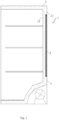
- an embodiment of the invention provides a refrigerator 1, comprising a shell 11 and a liner 13, with an insulating panel 3 and foamed polyurethane 5 set between the shell 11 and the liner 13, and the surface of the insulating material 3 being attached to the shell 11.
- an embodiment of the invention provides an insulating panel 3, comprising a vacuum insulation panel 31 and insulating material 33.
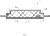
- the vacuum insulation panel 31 comprises a core material 311 and a coating material 313, the core material 311 provides an annular groove 315 on one side, and the coating material 313 envelops the core material 311, and a vacuum is formed between the core material 311 and the coating material 313.
- the core material 311 comprises at least one of glass fiber, glass wool, and fumed silica;
- the coating material 313 is configured as aluminum foil or aluminum vapor deposition that can block external gases;
- the insulating material 33 comprises at least one of expanded polystyrene, foamed polyurethane, expanded polyethylene, and expanded polypropylene.
- an adsorbent 317 is provided inside the core material 311, which used for absorbing gases escaping from the core material 311, further maintaining the vacuum inside the vacuum insulation panel 31.
- the core material 311 provides an annular groove 315 on one side
- the coating material 313 is a flexible material like aluminum foil or aluminum vapor deposition
- the vacuum insulation panel 31 also has an annular groove 315 structure, which formed by vacuuming after the coating material 313 envelops the core material 311.
- the top surface of the insulating material 33 and the vacuum insulation panel 31 are in the same plane, making the insulating panel 3 have a flat surface, that is convenient for attachment to applications like the refrigerator shell.
- the thickness of the annular groove 315 can be 1/2-2/3 of the thickness of the core material 311.
- the annular groove 315 can be positioned near the edge of the core material 311. Further, the annular groove 315 can be positioned such that one side end face is flush with the side end face of the core material 311. Since the insulating material 33 is placed in the annular groove 315 after the coating material 313 is enveloped, the end face of the adhered insulating material 33 and the end face of the vacuum insulation panel 31 are in the same plane, forming a rectangular cross-section for the insulating panel 3.
- the path of heat transfer through the surface of the coating material 313 becomes longer, further reducing the heat transfer to the inside of the refrigerator, thus enhancing the thermal insulation effect of the insulating panel 3.
- the smooth and flat surface of the insulating panel3 avoids the formation of narrow spaces where the foamed polyurethane cannot fill, preventing voids and surface defects.
- an embodiment of this invention provides a method for preparing an insulating panel, comprising the following steps: S 1. Preparation of core material.
- the core material of the insulating panel is configured as integrally formed, or configured as laminated after made into unit sizes. It can be understood that any production method for preparing a core material of a conventional shape can be used. Wherein, the core material may be at least one of glass fiber, glass wool and fumed silica.
- any conventional processing method such as milling, can be chosen for creating the annular groove.
- the thickness of the annular groove can be selected as 1/2-2/3 of the thickness of the core material, and the position of the annular groove can be near the edge of the core material's end face.
- the coating material is cut after multi-layer compounding to form a coating material bag.
- the coating material can be materials like aluminum foil or aluminum vapor deposition that can block external gases.
- the coating material bag After vacuum extraction of the core material and coating material bag, the coating material bag is heat-sealed, resulting in a vacuum insulation panel with the annular groove.
- the thermal resistance of the insulating material is higher than the thermal resistance of the coating material.
- Molds are prepared according to the size of the annular groove, and insulating material is prepared within the molds.
- the insulating material may be at least one of expanded polystyrene, foamed polyurethane, expanded polyethylene, and expanded polypropylene, or other materials with higher thermal resistance than the coating material.
- the cut insulating material has a relatively flat and smooth surface and can be fixed in the annular groove of the vacuum insulation panel using double-sided tape, roller glue, etc.
- the method for preparing the insulating panel provided by this invention is simple and easy to produce and process; meanwhile, the produced insulating panel achieves effective thermal insulation.
- a groove for accommodating an adsorbent is also created inside the core material, and an adsorbent is placed in it.
- the adsorbent can absorb gases escaping from within the core material, further ensuring the vacuum inside the insulating panel. Further, the adsorbent can be a calcium oxide adsorbent.
Landscapes
- Engineering & Computer Science (AREA)
- General Engineering & Computer Science (AREA)
- Mechanical Engineering (AREA)
- Chemical & Material Sciences (AREA)
- Combustion & Propulsion (AREA)
- Physics & Mathematics (AREA)
- Thermal Sciences (AREA)
- Thermal Insulation (AREA)
- Refrigerator Housings (AREA)
Abstract
Description
- This invention relates to the field of refrigeration appliances, and in particular, to an insulating panel, preparation method, as well as a refrigerator with the insulating panel.
- Vacuum insulation panels, a type of vacuum insulation material, are composed of a core material and a vacuum protective layer. They effectively prevent heat transfer caused by air convection. Currently, the application of vacuum insulation panels in refrigerators involves directly affixing flat vacuum insulation panels to the relatively flat surface of the refrigerator's shell, followed by foam filling. However, to maintain the internal vacuum, vacuum insulation panels often use materials like aluminum foil or aluminum vapor deposition for the overlay material. Due to aluminum's high thermal conductivity, heat transfers directly from one side to the other through the overlay material, leading to the "thermal bridging effect" at the edges of the vacuum insulation panel, resulting in poor energy efficiency at the edges.
- The existing technical solution involves adding a thin layer of insulation material between the vacuum insulation panel and the refrigerator shell during application. Since the size of the insulation material is smaller than that of the vacuum insulation panel, the edges of the vacuum insulation panel are suspended. During the foaming of polyurethane, the disorderliness of the foam material and the small thickness of the suspended space can lead to polyurethane not filling properly, resulting in voids and surface defects.
- An object of the present invention is to provide an insulating panel and its preparation method, as well as a refrigerator with the insulating panel.
- To achieve one of the above objects, an embodiment of the present invention provides an insulating panel, comprising a vacuum insulation panel and insulating material;
- the vacuum insulation panel comprises a core material and a coating material, wherein the core material provides an annular groove on one side, the coating material envelops the core material, and a vacuum is formed between the core material and the coating material;
- the insulating material is arranged in the annular groove enveloped by the coating material, the insulating material is located on the same plane as the vacuum insulation panel, and the thermal resistance of the insulating material is higher than the thermal resistance of the coating material.
- As a further improvement of the present invention, the coating material is configured as aluminum foil or aluminum vapor deposition.
- As a further improvement of the present invention, the core material comprises at least one of glass fiber, glass wool, and fumed silica.
- As a further improvement of the present invention, the insulating material comprises at least one of expanded polystyrene, foamed polyurethane, expanded polyethylene, and expanded polypropylene.
- As a further improvement of the present invention, the thickness of the annular groove is 1/2-2/3 of the thickness of the core material.
- As a further improvement of the present invention, one side end surface of the annular groove is flush with the side end surface of the core material, so that the adhered end surface of the insulating material and the vacuum insulation panel are in the same plane.
- As a further improvement of the present invention, an adsorbent is provided inside the core material.
- To achieve one of the above objects, an embodiment of the present invention provides a refrigerator, comprising a shell and a liner, wherein the insulating panel and foamed polyurethane according to
claim 1 are provided between the refrigerator shell and liner, with the surface of the insulating material being attached to the refrigerator shell. - To achieve one of the above objects, an embodiment of the present invention provides a method for preparing an insulating panel, wherein the method comprises the following steps: forming an annular groove on one side of the prepared core material; inserting the core material with the annular groove into a pre-fabricated coating material bag; vacuum extraction and heat sealing of the core material and coating material bag, obtaining a vacuum insulation panel with the annular groove; molding an insulating material according to the size of the annular groove, the thermal resistance of the insulating material is higher than the thermal resistance of the coating material; adhering the cut insulating material into the annular groove of the vacuum insulation panel, wherein the insulating material is in the same plane as the vacuum insulation panel.
- As a further improvement of an embodiment of the present invention, the core material of the insulating panel is configured as an integrally formed, or configured as laminated after made into unit sizes.
- Compared to existing technologies, the disclosed insulating panel, preparation method, and a refrigerator with the insulating panel, reduce the heat transfer to the edges and inside of the vacuum insulation panel through the insulating material. This reduction lowers the "thermal bridging effect" at the edges of the vacuum insulation panel, thereby achieving effective thermal insulation.
-
-
FIG. 1 a longitudinal sectional view of a refrigerator in an embodiment of the invention; -
FIG. 2 is a sectional view of the insulating panel in an embodiment of the invention; -
FIG. 3 is a sectional view of the vacuum insulation panel in an embodiment of the invention; -
FIG. 4 is a flow chart of the preparation method for the insulating panel in an embodiment of the invention. - The present invention will be described in detail in conjunction with embodiments shown in the figures. However, the embodiments are not intended to limit the present invention. Structural, methodological or function variations made by those having ordinary skill in the art according to the embodiments are all included in the protection scope of the present invention.
- It should be appreciated that terms indicating spatial relative positions such as "up", "down", "in" and "out" used in the text herein are intended to describe a relationship of one unit or feature shown in figures relative to another unit or feature for an easy description purpose. The terms indicating spatial relative positions may be intended to include different orientations besides the orientations shown in the figures in use or operation of the device.
- As shown in
Figure 1 , an embodiment of the invention provides arefrigerator 1, comprising ashell 11 and aliner 13, with an insulating panel 3 andfoamed polyurethane 5 set between theshell 11 and theliner 13, and the surface of the insulating material 3 being attached to theshell 11. - As shown in
Figure 2 , an embodiment of the invention provides an insulating panel 3, comprising avacuum insulation panel 31 andinsulating material 33. - As shown in
Figure 3 , thevacuum insulation panel 31 comprises acore material 311 and acoating material 313, thecore material 311 provides anannular groove 315 on one side, and thecoating material 313 envelops thecore material 311, and a vacuum is formed between thecore material 311 and thecoating material 313. - In this embodiment, the
core material 311 comprises at least one of glass fiber, glass wool, and fumed silica; thecoating material 313 is configured as aluminum foil or aluminum vapor deposition that can block external gases; theinsulating material 33 comprises at least one of expanded polystyrene, foamed polyurethane, expanded polyethylene, and expanded polypropylene. - Further, an adsorbent 317 is provided inside the
core material 311, which used for absorbing gases escaping from thecore material 311, further maintaining the vacuum inside thevacuum insulation panel 31. - In this embodiment, the
core material 311 provides anannular groove 315 on one side, and thecoating material 313 is a flexible material like aluminum foil or aluminum vapor deposition, it is understandable that thevacuum insulation panel 31 also has anannular groove 315 structure, which formed by vacuuming after thecoating material 313 envelops thecore material 311. - In this embodiment, when the external heat of the
refrigerator 1 is transferred to the insulating panel 3 through theshell 11, since theinsulating material 33 is placed in theannular groove 315 after thecoating material 313 is enveloped, and theinsulating material 33 is in the same plane as thevacuum insulation panel 31, the thermal resistance of theinsulating material 33 is higher than the thermal resistance of thecoating material 313; and the external heat of the refrigerator is transferred to the edge of thevacuum insulation panel 31 and the internal heat through the edge of theinsulating material 33 is reduced, this reduction lowers the "thermal bridging effect" at the edges of the vacuum insulation panel, also reducing the heat transferred to the inside of the refrigerator. - Additionally, in this embodiment, the top surface of the
insulating material 33 and thevacuum insulation panel 31 are in the same plane, making the insulating panel 3 have a flat surface, that is convenient for attachment to applications like the refrigerator shell. - In this embodiment, the thickness of the
annular groove 315 can be 1/2-2/3 of the thickness of thecore material 311. Theannular groove 315 can be positioned near the edge of thecore material 311. Further, theannular groove 315 can be positioned such that one side end face is flush with the side end face of thecore material 311. Since theinsulating material 33 is placed in theannular groove 315 after thecoating material 313 is enveloped, the end face of the adheredinsulating material 33 and the end face of thevacuum insulation panel 31 are in the same plane, forming a rectangular cross-section for the insulating panel 3. With a rectangular cross-section, the path of heat transfer through the surface of thecoating material 313 becomes longer, further reducing the heat transfer to the inside of the refrigerator, thus enhancing the thermal insulation effect of the insulating panel 3. Moreover, when therefrigerator shell 11 andliner 13 are filled withfoamed polyurethane 5, the smooth and flat surface of the insulating panel3 avoids the formation of narrow spaces where the foamed polyurethane cannot fill, preventing voids and surface defects. - As shown in
Figure 4 , an embodiment of this invention provides a method for preparing an insulating panel, comprising the following steps:
S 1. Preparation of core material. - The core material of the insulating panel is configured as integrally formed, or configured as laminated after made into unit sizes. It can be understood that any production method for preparing a core material of a conventional shape can be used. Wherein, the core material may be at least one of glass fiber, glass wool and fumed silica.
- S2. Forming an annular groove on one side of the prepared core material.
- Any conventional processing method, such as milling, can be chosen for creating the annular groove. Specifically, the thickness of the annular groove can be selected as 1/2-2/3 of the thickness of the core material, and the position of the annular groove can be near the edge of the core material's end face.
- S3. Preparation of the coating material bag.
- The coating material is cut after multi-layer compounding to form a coating material bag. Specifically, the coating material can be materials like aluminum foil or aluminum vapor deposition that can block external gases.
- S4. Inserting the core material with the annular groove into a pre-fabricated coating material bag.
- S5. Vacuum extraction and heat sealing of the core material and coating material bag, obtaining a vacuum insulation panel with an annular groove.
- After vacuum extraction of the core material and coating material bag, the coating material bag is heat-sealed, resulting in a vacuum insulation panel with the annular groove.
- S6. Molding an insulating material according to the size of the annular groove, the thermal resistance of the insulating material is higher than the thermal resistance of the coating material.
- Molds are prepared according to the size of the annular groove, and insulating material is prepared within the molds. The insulating material may be at least one of expanded polystyrene, foamed polyurethane, expanded polyethylene, and expanded polypropylene, or other materials with higher thermal resistance than the coating material.
- S7. Adhering the cut insulating material into the annular groove of the vacuum insulation panel, wherein the insulating material is in the same plane as the vacuum insulation panel.
- In this embodiment, the cut insulating material has a relatively flat and smooth surface and can be fixed in the annular groove of the vacuum insulation panel using double-sided tape, roller glue, etc.
- The method for preparing the insulating panel provided by this invention is simple and easy to produce and process; meanwhile, the produced insulating panel achieves effective thermal insulation.
- In this embodiment, while processing the annular groove on the surface of the core material, a groove for accommodating an adsorbent is also created inside the core material, and an adsorbent is placed in it. The adsorbent can absorb gases escaping from within the core material, further ensuring the vacuum inside the insulating panel. Further, the adsorbent can be a calcium oxide adsorbent.
- It should be understood that although this specification describes the invention according to embodiments, not every embodiment contains an independent technical solution. This manner of description is solely for clarity. Those skilled in the art should consider this specification as a whole. Technical solutions from various embodiments can be appropriately combined to form other implementations understood by those skilled in the art.
Claims (10)
- An insulating panel, comprising a vacuum insulation panel and insulating material;the vacuum insulation panel comprises a core material and a coating material, wherein the core material provides an annular groove on one side, the coating material envelops the core material, and a vacuum is formed between the core material and the coating material;the insulating material is arranged in the annular groove enveloped by the coating material, the insulating material is located on the same plane as the vacuum insulation panel, and the thermal resistance of the insulating material is higher than the thermal resistance of the coating material.
- The insulating panel according to claim 1, wherein the coating material is configured as aluminum foil or aluminum vapor deposition.
- The insulating panel according to claim 1, wherein the core material comprises at least one of glass fiber, glass wool, and fumed silica.
- The insulating panel according to claim 1, wherein the insulating material comprises at least one of expanded polystyrene, foamed polyurethane, expanded polyethylene, and expanded polypropylene.
- The insulating panel according to claim 1, wherein the thickness of the annular groove is 1/2-2/3 of the thickness of the core material.
- The insulating panel according to claim 1, wherein one side end surface of the annular groove is flush with the side end surface of the core material, so that the adhered end surface of the insulating material and the vacuum insulation panel are in the same plane.
- The insulating panel according to claim 1, wherein an adsorbent is provided inside the core material.
- A refrigerator, comprising a shell and a liner, wherein the insulating panel and foamed polyurethane according to claim 1 are provided between the refrigerator shell and liner, with the surface of the insulating material being attached to the refrigerator shell.
- A method for preparing an insulating panel, wherein the method comprises the following steps: forming an annular groove on one side of the prepared core material; inserting the core material with the annular groove into a pre-fabricated coating material bag; vacuum extraction and heat sealing of the core material and coating material bag, obtaining a vacuum insulation panel with the annular groove; molding an insulating material according to the size of the annular groove, the thermal resistance of the insulating material is higher than the thermal resistance of the coating material; adhering the cut insulating material into the annular groove of the vacuum insulation panel, wherein the insulating material is in the same plane as the vacuum insulation panel.
- The method for preparing an insulating panel according to claim 9, wherein the core material of the insulating panel is configured as an integrally formed, or configured as laminated after made into unit sizes.
Applications Claiming Priority (2)
| Application Number | Priority Date | Filing Date | Title |
|---|---|---|---|
| CN202110718600.1A CN115596930A (en) | 2021-06-28 | 2021-06-28 | Heat insulation board, preparation method thereof and refrigerator applying heat insulation board |
| PCT/CN2022/100768 WO2023274022A1 (en) | 2021-06-28 | 2022-06-23 | Thermal insulation board and preparation method therefor and refrigerator using thermal insulation board |
Publications (3)
| Publication Number | Publication Date |
|---|---|
| EP4365474A1 true EP4365474A1 (en) | 2024-05-08 |
| EP4365474A4 EP4365474A4 (en) | 2024-10-02 |
| EP4365474B1 EP4365474B1 (en) | 2026-05-06 |
Family
ID=84691377
Family Applications (1)
| Application Number | Title | Priority Date | Filing Date |
|---|---|---|---|
| EP22831838.2A Active EP4365474B1 (en) | 2021-06-28 | 2022-06-23 | Thermal insulation board and preparation method therefor and refrigerator using thermal insulation board |
Country Status (5)
| Country | Link |
|---|---|
| US (1) | US20240318764A1 (en) |
| EP (1) | EP4365474B1 (en) |
| CN (1) | CN115596930A (en) |
| AU (1) | AU2022300959A1 (en) |
| WO (1) | WO2023274022A1 (en) |
Family Cites Families (21)
| Publication number | Priority date | Publication date | Assignee | Title |
|---|---|---|---|---|
| JPS5796852A (en) * | 1980-12-09 | 1982-06-16 | Matsushita Electric Industrial Co Ltd | Heat insulating material |
| US5532034A (en) * | 1994-12-06 | 1996-07-02 | Whirlpool Corporation | Getter system for vacuum insulation panel |
| DE29613093U1 (en) * | 1996-07-29 | 1997-11-27 | Bayer Ag, 51373 Leverkusen | Fixed vacuum insulation panel as well as a refrigeration cabinet element containing this fixed vacuum insulation panel |
| JPH11201379A (en) * | 1998-01-13 | 1999-07-30 | Sanyo Electric Co Ltd | Vacuum heat insulating material and manufacture thereof |
| JP3709762B2 (en) * | 2000-04-18 | 2005-10-26 | いすゞ自動車株式会社 | Vacuum insulation and insulation panel |
| JP2011153721A (en) * | 2010-01-26 | 2011-08-11 | Hitachi Appliances Inc | Refrigerator |
| CN201739710U (en) * | 2010-04-20 | 2011-02-09 | 福建赛特新材料有限公司 | Vacuum insulation panel with groove on surface |
| KR101280776B1 (en) * | 2010-09-14 | 2013-07-05 | 히타치 어플라이언스 가부시키가이샤 | Vacuum insulation panel and refrigerator using this |
| JP2014005887A (en) * | 2012-06-25 | 2014-01-16 | Toshiba Corp | Vacuum heat insulation panel, and refrigerator using vacuum heat insulation panel |
| KR102163292B1 (en) * | 2013-07-26 | 2020-10-08 | 삼성전자주식회사 | Vacuum heat insulating material and refrigerator including the same |
| JP2015140885A (en) * | 2014-01-29 | 2015-08-03 | 旭ファイバーグラス株式会社 | Vacuum heat insulation material |
| CN104964124A (en) * | 2014-08-01 | 2015-10-07 | 常州山由帝奥绝缘材料制造有限公司 | Vacuum insulation board having gaps and/or through holes and method for producing same |
| US10603865B2 (en) * | 2014-12-25 | 2020-03-31 | AGC Inc. | Insulating member and its attaching method |
| WO2016162955A1 (en) * | 2015-04-07 | 2016-10-13 | 三菱電機株式会社 | Vacuum insulation material, and refrigerator |
| KR102525551B1 (en) * | 2015-08-03 | 2023-04-25 | 엘지전자 주식회사 | Vacuum adiabatic body and refrigerator |
| CN205316798U (en) * | 2015-12-15 | 2016-06-15 | 合肥华凌股份有限公司 | Vacuum insulated board and refrigerator |
| CN105371580B (en) * | 2015-12-15 | 2019-01-15 | 合肥华凌股份有限公司 | Vacuum heat-insulating plate and refrigerator |
| CN107461569A (en) * | 2016-06-06 | 2017-12-12 | 福建赛特新材股份有限公司 | The hole-opening foaming structural member and vacuum heat-insulating plate of a kind of vacuum heat-insulating plate |
| JP2019168001A (en) * | 2018-03-22 | 2019-10-03 | 東芝ライフスタイル株式会社 | Vacuum heat insulating material and refrigerator using vacuum heat insulating material |
| CN109707954A (en) * | 2018-12-28 | 2019-05-03 | 青岛海尔股份有限公司 | Vacuum heat-insulating plate and refrigerator with it |
| CN111907154B (en) * | 2019-05-09 | 2023-04-07 | 青岛海尔电冰箱有限公司 | Vacuum heat insulation plate, manufacturing method of vacuum heat insulation plate and refrigerator |
-
2021
- 2021-06-28 CN CN202110718600.1A patent/CN115596930A/en active Pending
-
2022
- 2022-06-23 US US18/574,639 patent/US20240318764A1/en active Pending
- 2022-06-23 EP EP22831838.2A patent/EP4365474B1/en active Active
- 2022-06-23 WO PCT/CN2022/100768 patent/WO2023274022A1/en not_active Ceased
- 2022-06-23 AU AU2022300959A patent/AU2022300959A1/en not_active Abandoned
Also Published As
| Publication number | Publication date |
|---|---|
| WO2023274022A1 (en) | 2023-01-05 |
| EP4365474A4 (en) | 2024-10-02 |
| CN115596930A (en) | 2023-01-13 |
| US20240318764A1 (en) | 2024-09-26 |
| AU2022300959A1 (en) | 2024-01-18 |
| EP4365474B1 (en) | 2026-05-06 |
Similar Documents
| Publication | Publication Date | Title |
|---|---|---|
| KR100507783B1 (en) | Heat insulation box, and vacuum heat insulation material used therefor | |
| EP1275893B1 (en) | Vacuum insulating material and device using the same | |
| KR101495127B1 (en) | Vacuum heat insulation member and refrigerator using same | |
| CN103575039B (en) | Heat insulating box and possess the refrigerator of this heat insulating box | |
| JP2009024922A (en) | refrigerator | |
| WO2010137081A1 (en) | Refrigerator equipped with vacuum insulation material | |
| JP2013061131A (en) | Refrigerator having vacuum heat insulating material | |
| JP2009024921A (en) | refrigerator | |
| EP4365474A1 (en) | Thermal insulation board and preparation method therefor and refrigerator using thermal insulation board | |
| CN106121071A (en) | A kind of vacuum heat-insulating plate and processing method thereof | |
| JPWO2014122939A1 (en) | Thermal insulation panel | |
| CN211440861U (en) | A kind of sidewall protection device for composite phenolic resin air conditioning insulation board production line | |
| KR20120034511A (en) | Vacuum insulation panel, refrigerator with vacuum insulation panel and manufacturing method for vacuum insulation panel | |
| JP2005140407A (en) | Thermal insulation wall and refrigerator | |
| CN110552434A (en) | Vacuum insulated panel foaming integrated board | |
| EP3181980B1 (en) | Method for manufacturing vacuum heat insulator and vacuum heat insulator | |
| JP2017106588A (en) | Vacuum insulation | |
| JP6431291B2 (en) | Building material panel and manufacturing method thereof | |
| JP2015055368A (en) | Vacuum heat insulation material and refrigerator using the same | |
| CN107816601A (en) | Vacuumed insulation panel | |
| JP2007211913A (en) | Thermal insulation panel | |
| CN212842440U (en) | A vacuum insulation panel and refrigerator | |
| JP6000922B2 (en) | Vacuum heat insulating material and cooling / heating equipment using the same | |
| CN207180153U (en) | refrigerator | |
| JP2007178077A (en) | refrigerator |
Legal Events
| Date | Code | Title | Description |
|---|---|---|---|
| STAA | Information on the status of an ep patent application or granted ep patent |
Free format text: STATUS: THE INTERNATIONAL PUBLICATION HAS BEEN MADE |
|
| PUAI | Public reference made under article 153(3) epc to a published international application that has entered the european phase |
Free format text: ORIGINAL CODE: 0009012 |
|
| STAA | Information on the status of an ep patent application or granted ep patent |
Free format text: STATUS: REQUEST FOR EXAMINATION WAS MADE |
|
| 17P | Request for examination filed |
Effective date: 20231222 |
|
| AK | Designated contracting states |
Kind code of ref document: A1 Designated state(s): AL AT BE BG CH CY CZ DE DK EE ES FI FR GB GR HR HU IE IS IT LI LT LU LV MC MK MT NL NO PL PT RO RS SE SI SK SM TR |
|
| A4 | Supplementary search report drawn up and despatched |
Effective date: 20240902 |
|
| DAV | Request for validation of the european patent (deleted) | ||
| DAX | Request for extension of the european patent (deleted) | ||
| RIC1 | Information provided on ipc code assigned before grant |
Ipc: B32B 3/02 20060101ALI20240827BHEP Ipc: F25D 23/08 20060101ALI20240827BHEP Ipc: F25D 23/06 20060101ALI20240827BHEP Ipc: F16L 59/02 20060101ALI20240827BHEP Ipc: F16L 59/065 20060101AFI20240827BHEP |
|
| GRAP | Despatch of communication of intention to grant a patent |
Free format text: ORIGINAL CODE: EPIDOSNIGR1 |
|
| STAA | Information on the status of an ep patent application or granted ep patent |
Free format text: STATUS: GRANT OF PATENT IS INTENDED |
|
| INTG | Intention to grant announced |
Effective date: 20251219 |
|
| GRAS | Grant fee paid |
Free format text: ORIGINAL CODE: EPIDOSNIGR3 |
|
| GRAA | (expected) grant |
Free format text: ORIGINAL CODE: 0009210 |
|
| STAA | Information on the status of an ep patent application or granted ep patent |
Free format text: STATUS: THE PATENT HAS BEEN GRANTED |